Embed Size (px)
Citation preview

303-01C-1 303-01C-1Engine — 6.0L Diesel
IN-VEHICLE REPAIR
Intake Manifold
Material
Item Specification
Motorcraft Premium Gold WSS-M97B51-A1Engine CoolantVC-7-A (in California,Oregon and New MexicoVC-7-B, in CanadaCVC-7-A)
Removal
Vehicles with dual generatorsAll vehicles
6. Remove the accessory drive belt.1. Remove the auxiliary battery. For additionalinformation, refer to Section 414-01.
2. Remove the cooling fan stator — 6.0L dieselengine. For additional information, refer toSection 303-03.
3. Remove the degas bottle. For additionalinformation, refer to Section 303-03.
4. Remove the upper radiator hose.
7. Remove the bolt and the accessory drive belttensioner.
5. NOTE: Engine side shown, charge air coolerside similar.
Remove the turbocharger-to-charge air cooler(CAC) duct.
Copyright 2004, Ford Motor CompanyLast updated: 1/10/2005 2005 F-250, 350, 450, 550 Super Duty, 10/2004

303-01C-2 303-01C-2Engine — 6.0L Diesel
IN-VEHICLE REPAIR (Continued)
8. Remove the accessory drive belt.
12. Remove the bolts and the generator withmounting bracket.
9. Remove the bolts, bracket and accessory drivebelt idler pulley.
Vehicles with single generator
10. Remove the bolts and the accessory drive belt 13. Remove the accessory drive belt.tensioner.
11. Disconnect the wire retainer, generator electricalconnector and B+ wire.
2005 F-250, 350, 450, 550 Super Duty, 10/2004

303-01C-3 303-01C-3Engine — 6.0L Diesel
IN-VEHICLE REPAIR (Continued)
All vehicles 18. Remove the bolts and position the heater hosetube aside.
14. Position the boot back and disconnect the • Remove and discard the O-ring.generator B+ wire and electrical connector.
19. Disconnect the manifold absolute pressure15. Remove the three bolts and the generator. (MAP) sensor hose.
16. Remove the turbocharger and the turbocharger 20. Disconnect the engine coolant vent hose.pedestal. For additional information, refer toSection 303-04D.
17. NOTE: Engine side shown, CAC side similar.
Loosen the clamps and remove the CAC duct.
21. Remove the fuel injector control module. Foradditional information, refer to Section303-14B.
2005 F-250, 350, 450, 550 Super Duty, 10/2004

303-01C-4 303-01C-4Engine — 6.0L Diesel
IN-VEHICLE REPAIR (Continued)
22. If equipped with a heat shield bracket, remove 25. NOTE: Early build shown, late build similar.the retaining nuts from the heat shield bracket. Remove the top two bolts from the injector• Disconnect the ground wire from the stud. pressure regulator (IPR) heat shield.
23. If equipped with a heat shield bracket, 26. Position back the heat insulating wrap.disconnect the wiring retainer from the heat Disconnect the wiring retainer and injectorshield bracket. pressure regulator valve electrical connectors.
24. If equipped with a heat shield bracket, remove 27. Disconnect the exhaust gas recirculation (EGR)the bolts and heat shield bracket. valve electrical connector.
2005 F-250, 350, 450, 550 Super Duty, 10/2004

303-01C-5 303-01C-5Engine — 6.0L Diesel
IN-VEHICLE REPAIR (Continued)
28. Disconnect the engine oil pressure (EOP) sensor 31. Disconnect the intake air temperature (IAT2)electrical connector. sensor electrical connector.
Early build vehicles29. Disconnect the engine oil temperature (EOT)sensor electrical connector.
32. Disconnect the exhaust pressure (EP) sensorelectrical connector.
30. Disconnect the pin-type retainer and enginecoolant temperature (ECT) sensor.
2005 F-250, 350, 450, 550 Super Duty, 10/2004
303-01C-6 303-01C-6Engine — 6.0L Diesel
IN-VEHICLE REPAIR (Continued)
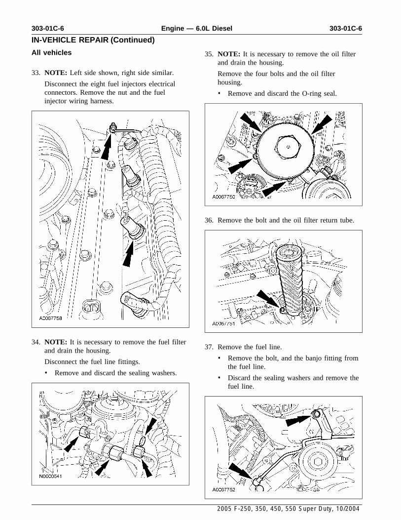
All vehicles 35. NOTE: It is necessary to remove the oil filterand drain the housing.
33. NOTE: Left side shown, right side similar. Remove the four bolts and the oil filterhousing.Disconnect the eight fuel injectors electrical
connectors. Remove the nut and the fuel • Remove and discard the O-ring seal.injector wiring harness.
36. Remove the bolt and the oil filter return tube.
34. NOTE: It is necessary to remove the fuel filter37. Remove the fuel line.and drain the housing.
• Remove the bolt, and the banjo fitting fromDisconnect the fuel line fittings.the fuel line.
• Remove and discard the sealing washers.• Discard the sealing washers and remove the
fuel line.
2005 F-250, 350, 450, 550 Super Duty, 10/2004

303-01C-7 303-01C-7Engine — 6.0L Diesel
IN-VEHICLE REPAIR (Continued)
38. NOTE: Align the flat edge with the index 41. NOTE: Keep the EGR cooler V-clamp with thefeature located on the coolant supply port. turbo adapter pipe.
Pull the EGR cooler clamp forward, twist and Remove the bolts and the intake manifold.then slide the EGR cooler hose rearward toremove.
42. Remove the intake manifold gaskets.
• Clean and inspect the gaskets. Install new39. NOTE: LH shown, RH similar. gaskets if necessary.
Loosen the nuts and bolts from the turbocharger • Clean and inspect the sealing surfaces.adapter pipe.
40. Loosen the EGR cooler V-clamp.
2005 F-250, 350, 450, 550 Super Duty, 10/2004

303-01C-8 303-01C-8Engine — 6.0L Diesel
IN-VEHICLE REPAIR (Continued)
Installation
All vehicles
1. NOTE: The locating tabs on the gaskets mustbe up and positioned toward the center of theengine, or a leak will occur.
Install the intake manifold gaskets and frontmodule O-ring seal.
2. NOTE: When installing the manifold, apply aslight amount of all purpose grease to themating surface of the EGR tube to keep the
3. Position the EGR cooler V-clamp over the EGREGR gasket in place.tube.
NOTE: Install the EGR cooler V-clamp looselyin place on the turbo adapter pipe. 4. Install the gasket and the EGR cooler V-clamp.Install the intake manifold and loosely installthe bolts. Tighten the intake manifold bolts inthe sequence shown.
1 Tighten bolts 9-16 to 11 Nm (8 lb-ft).
2 Tighten all bolts to 11 Nm (8 lb-ft) in thesequence shown.
2005 F-250, 350, 450, 550 Super Duty, 10/2004
303-01C-9 303-01C-9Engine — 6.0L Diesel
IN-VEHICLE REPAIR (Continued)
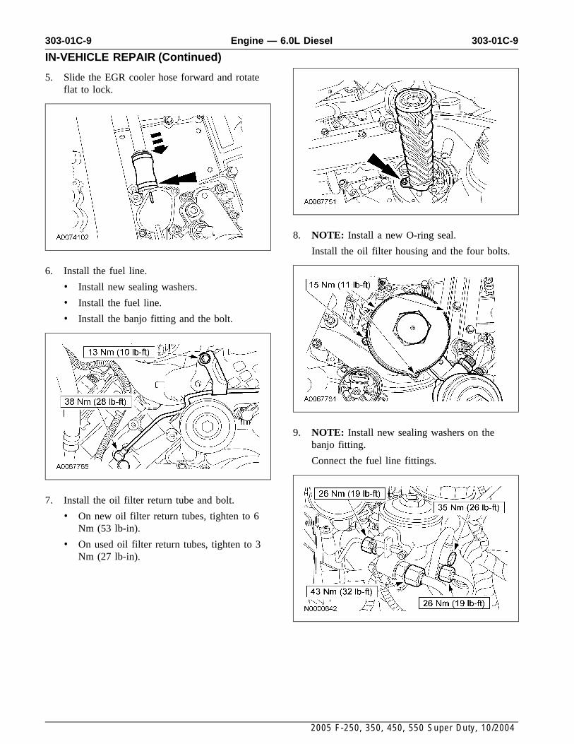
5. Slide the EGR cooler hose forward and rotateflat to lock.
8. NOTE: Install a new O-ring seal.
Install the oil filter housing and the four bolts.
6. Install the fuel line.
• Install new sealing washers.
• Install the fuel line.
• Install the banjo fitting and the bolt.
9. NOTE: Install new sealing washers on thebanjo fitting.
Connect the fuel line fittings.
7. Install the oil filter return tube and bolt.
• On new oil filter return tubes, tighten to 6Nm (53 lb-in).
• On used oil filter return tubes, tighten to 3Nm (27 lb-in).
2005 F-250, 350, 450, 550 Super Duty, 10/2004
303-01C-10 303-01C-10Engine — 6.0L Diesel
IN-VEHICLE REPAIR (Continued)
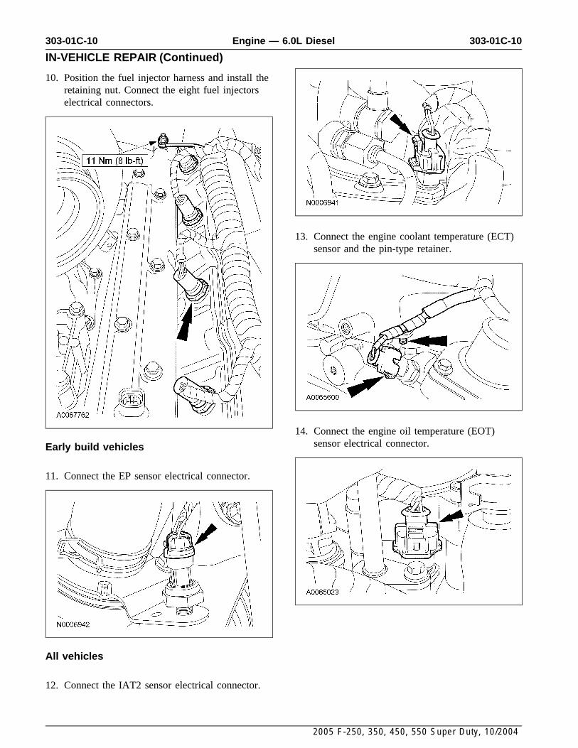
10. Position the fuel injector harness and install theretaining nut. Connect the eight fuel injectorselectrical connectors.
13. Connect the engine coolant temperature (ECT)sensor and the pin-type retainer.
14. Connect the engine oil temperature (EOT)sensor electrical connector.Early build vehicles
11. Connect the EP sensor electrical connector.
All vehicles
12. Connect the IAT2 sensor electrical connector.
2005 F-250, 350, 450, 550 Super Duty, 10/2004

303-01C-11 303-01C-11Engine — 6.0L Diesel
IN-VEHICLE REPAIR (Continued)
15. Connect the engine oil pressure (EOP) sensorelectrical connector.
19. If equipped with a heat shield bracket, installthe heat shield bracket and bolts.
16. Connect the EGR valve electrical connector.
20. If equipped with a heat shield bracket, connectthe wiring retainer to the back of the heat
17. Connect the wiring retainer and injector shield bracket.pressure regulator electrical connector. Positionback the heat insulating wrap.
18. NOTE: Early build shown, late build similar.
Install the top two bolts to the injector IPR heatshield.
2005 F-250, 350, 450, 550 Super Duty, 10/2004

303-01C-12 303-01C-12Engine — 6.0L Diesel
IN-VEHICLE REPAIR (Continued)
21. If equipped with a heat shield bracket, position 25. NOTE: Install a new O-ring seal on the heaterback the ground wire and install the retaining hose tube.nuts. Install the heater hose tube and bolts.
22. Install the fuel injector control module. For 26. NOTE: Engine side shown, charge-air-cooleradditional information, refer to Section (CAC) side similar.303-14B.
Install the CAC duct and tighten the clamps.
23. Connect the engine coolant vent hose andclamp.
27. Install the turbocharger pedestal andturbocharger. For additional information, referto Section 303-04D.24. Connect the MAP sensor hose.
2005 F-250, 350, 450, 550 Super Duty, 10/2004

303-01C-13 303-01C-13Engine — 6.0L Diesel
IN-VEHICLE REPAIR (Continued)
28. NOTE: Alternately tighten the bolts tospecification.
Tighten the nuts and bolts in the adapter pipe.
Vehicles with dual generators
32. Install the generator with mounting bracket andbolts.
29. Install the generator and the three bolts.
33. Connect the B+ wire, generator electricalconnector and wire retainer.30. Connect the generator B+ wire land electrical
connector and position the boot back.
Vehicles with single generator
31. Install the accessory drive belt.
2005 F-250, 350, 450, 550 Super Duty, 10/2004

303-01C-14 303-01C-14Engine — 6.0L Diesel
IN-VEHICLE REPAIR (Continued)
34. Install the accessory drive belt tensioner andbolts.
38. Install the accessory drive belt.
35. Position the accessory drive belt idler pulley.Install the bracket and bolts.
All vehicles
39. NOTE: Engine side shown, CAC side similar.
NOTE: If there is any oil residue, clean both36. Install the accessory drive belt.connecting ports and the inside surface of thecharge air cooler duct to prevent the duct fromblowing off.
Install the turbocharger-to-CAC duct.
37. Install the accessory drive belt tensioner andbolt.
2005 F-250, 350, 450, 550 Super Duty, 10/2004

303-01C-15 303-01C-15Engine — 6.0L Diesel
IN-VEHICLE REPAIR (Continued)
40. Install the upper radiator hose. 41. Install the degas bottle. For additionalinformation, refer to Section 303-03.
42. Install the auxiliary battery. For additionalinformation, refer to Section 414-01.
43. Install the cooling fan stator — 6.0L dieselengine. For additional information, refer toSection 303-03.
2005 F-250, 350, 450, 550 Super Duty, 10/2004