Embed Size (px)
Citation preview
DETAIL SPECIFICATION
CONNECTORS, ELECTRICAL, CIRCULAR, MINIATURE, HIGH DENSITY, QUICK DISCONNECT (BAYONET, THREADED, AND BREECH COUPLING), ENVIRONMENT RESISTANT,
REMOVABLE CRIMP AND HERMETIC SOLDER CONTACTS, GENERAL SPECIFICATION FOR
This specification is approved for use by all Departments and Agencies of the Department of Defense.
1. SCOPE 1.1 Scope. This specification covers four series of miniature, high density, bayonet, threaded, or
breech coupling, circular, environment resistant, electrical connectors using removable crimp or fixed hermetic solder contacts, and are capable of operation within a temperature range of -65°C to +200°C (see 1.3.1d). See 6.1 for intended use and applications.
1.2 Description. All series include rear release removable pin and socket contacts with crimp
termination. All series are designed to assure proper orientation of the mating halves prior to electrical circuit closure. All series include hermetically sealed receptacles with fixed contacts for solder termination. All series include EMI shielding capability. Series I, III, and IV connectors with conductive finishes provide electrical continuity between mated shells prior to contact engagement and have the contacts so located as to be protected from handling damage and inadvertent electrical contact. Series II provides low silhouette for minimum size and weight and includes connectors which provide shell-to-shell electrical continuity when mated.
1.3 Classification. 1.3.1 Connectors. Connectors fabricated to this specification are classified as follows:
a. Series: The series I, II, III, and IV connectors are not interchangeable or intermateable.
I - Scoop-proof, bayonet coupling, (inch-pound dimensions and measurements).
II - Non-scoop-proof, bayonet coupling, low silhouette, (inch-pound dimensions and measurements).
III - Scoop-proof, triple start, self-locking, threaded coupling, (metric dimensions and measurements).
IV - Scoop-proof, breech coupling, (metric dimensions and measurements).
AMSC N/A FSC 5935
MIL-DTL-38999L w/AMENDMENT 1 30 July 2009 SUPERSEDING MIL-DTL-38999L 30 May 2008
Comments, suggestions, or questions on this document should be addressed to Defense Supply Center Columbus, ATTN: VAI, P.O. Box 3990, Columbus OH 43218-3990 or emailed to [email protected]. Since contact information can change, you may want to verify the currency of this address information using the ASSIST Online database at http://assist.daps.dla.mil.
INCH-POUND
Downloaded from http://www.everyspec.com
MIL-DTL-38999L w/AMENDMENT 1
2
b. Types:
(1) Plugs:
- Straight, without spring fingers. - Straight, with spring fingers that make contact to receptacle shell prior to contact engagement. - Straight, with spring fingers that make contact to receptacle shell after contacts engage. - Lanyard release.
(2) Receptacles:
- Box mounting, both front and rear panel mounting. - Wall mounting, both front and rear panel mounting. - Jam nut, rear panel mounting. - Solder mounting. - Thru-bulkhead.
c. Classes:
Series I and II:
E - Environment resisting - Box and thru-bulkhead mounting receptacle types. Other types with rear accessories are inactive for new design.
G - Environment resisting - wall and jam nut mounting receptacle and plug types, space grade.
H - Hermetically sealed - space grade. P - For potting - Includes potting form and short rear grommet. Inactive for new design for
Air Force. T - Environment resisting - Wall and jam nut mounting receptacle and plug types. These
designs incorporate provisions (thread and teeth) for rear accessory attachment. Y - Hermetically sealed.
Series III and IV:
C - Environment resisting - Nonconductive plating. F - Environment resisting - Conductive plating. G - Environment resisting - Conductive plating, space grade. H - Hermetically sealed - Corrosion resistant steel, passivated, space grade. J - Environment resisting - Conductive, corrosion resistant composite. K - Environment resisting - Corrosion resistant steel with firewall barrier. L - Environment resisting - Corrosion resistant steel, electrodeposited nickel. M - Environment resisting - Conductive, corrosion resistant composite. N - Hermetically sealed - Corrosion resistant steel, electrodeposited nickel. P - Environment resisting - Pure electrodeposited aluminum, conductive plating. R - Same as F, but higher corrosion requirement. S - Environment resisting - Corrosion resistant steel, electrodeposited nickel with firewall
barrier. T - Environment resisting - Nickel fluorocarbon polymer, conductive plating. W - Environment resisting - Corrosion resistant plating. X - Same as W, but higher corrosion requirement. Y - Hermetically sealed - Corrosion resistant steel, passivated. Z - Environment resisting - Zinc nickel, conductive plating.
Downloaded from http://www.everyspec.com
MIL-DTL-38999L w/AMENDMENT 1
3
d. Temperature ranges: The upper temperature is the maximum internal hotspot temperature resulting from any combination of electrical load and ambient conditions.
Series I and II finishes:
A - Silver to light iridescent yellow color cadmium plate over nickel (conductive) -65°C to +150°C (inactive for new design). B - Olive-drab cadmium plate over a suitable underplate (conductive) -65°C to +175°C. C - Anodic (nonconductive) -65°C to +200°C. D - Fused tin, carbon steel (conductive) -65°C to +150°C. E - Corrosion resistant steel, passivated (conductive) -65°C to +200°C. F - Electroless nickel coating (conductive) -65°C to +200°C. N - Hermetic seal or environment resisting corrosion resistant steel (conductive plating) -65°C to +200°C. P - Pure electrodeposited aluminum (conductive) -65°C to +175°C. R - Same as F, but higher corrosion requirement -65°C to +200°C. T - Nickel fluorocarbon polymer (conductive) -65°C to +175°C. U - Same as A, but higher corrosion requirement -65°C to +150°C. X - Same as B, but higher corrosion requirement -65°C to +150°C. Z - Zinc nickel (conductive) -65°C to +175°C. Series III and IV classes: C - Anodic (nonconductive) -65°C to +200°C. F - Electroless nickel coating (conductive) -65°C to +200°C. G - Same as F but space grade -65°C to +200°C. H - Same as Y but space grade -65°C to +200°C. J - Olive-drab cadmium plate, composite (conductive) -65°C to +175°C. K - Corrosion resistant steel passivated (conductive) -65°C to +200°C. L - Corrosion resistant steel with electrodeposited nickel plating (conductive) -65°C to +200°C. M - Electroless nickel coating, composite (conductive) -65°C to +200°C. N - Corrosion resistant steel with electrodeposited nickel plating (conductive) -65°C to +200°C. P - Pure electrodeposited aluminum (conductive) -65°C to +175°C. R - Same as F, but higher corrosion requirement -65°C to +200°C. S - Corrosion resistant steel with electrodeposited nickel plating (conductive) -65°C to +200°C. T - Nickel fluorocarbon polymer over a suitable underplate (conductive) -65°C to +175°C. W - Olive-drab cadmium plate over a suitable underplate (conductive) -65°C to +175°C. X - Same as W, but higher corrosion requirement -65°C to +175°C. Y - Corrosion resistant steel passivated (conductive) -65°C to +200°C. Z - Zinc nickel over a suitable underplate (conductive) -65°C to +175°C.
Downloaded from http://www.everyspec.com
MIL-DTL-38999L w/AMENDMENT 1
4
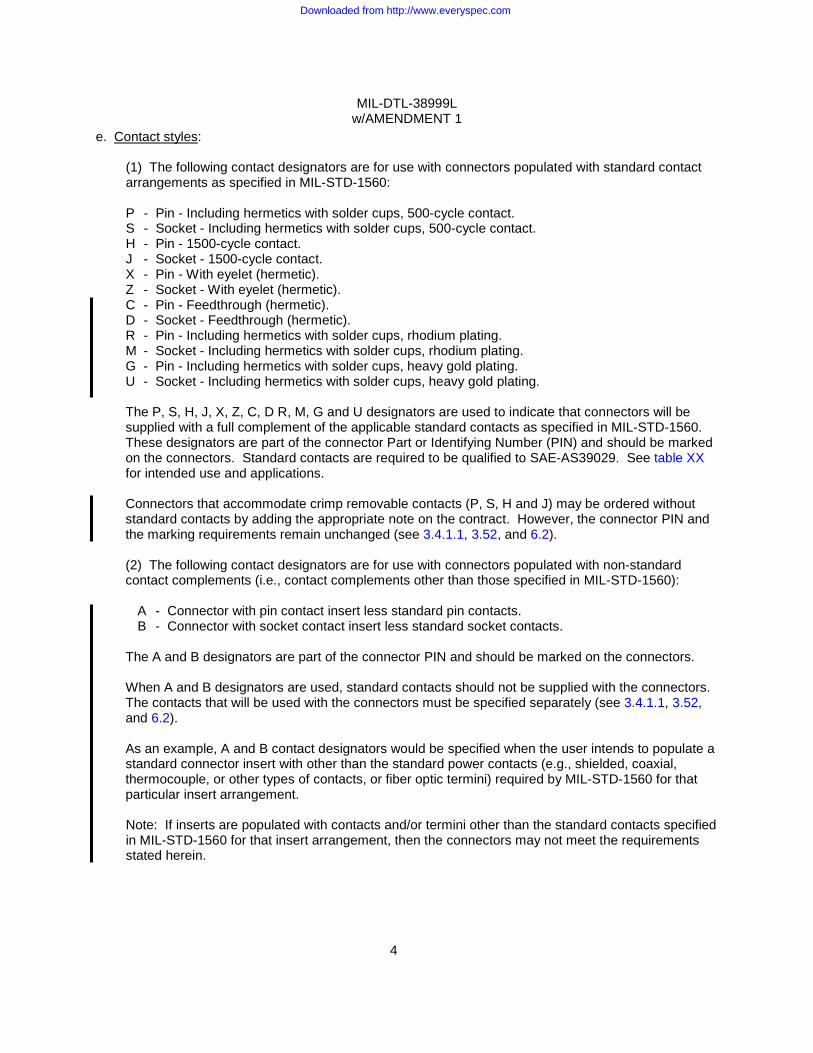
e. Contact styles:
(1) The following contact designators are for use with connectors populated with standard contact arrangements as specified in MIL-STD-1560: P - Pin - Including hermetics with solder cups, 500-cycle contact. S - Socket - Including hermetics with solder cups, 500-cycle contact. H - Pin - 1500-cycle contact. J - Socket - 1500-cycle contact. X - Pin - With eyelet (hermetic). Z - Socket - With eyelet (hermetic). C - Pin - Feedthrough (hermetic). D - Socket - Feedthrough (hermetic). R - Pin - Including hermetics with solder cups, rhodium plating. M - Socket - Including hermetics with solder cups, rhodium plating. G - Pin - Including hermetics with solder cups, heavy gold plating. U - Socket - Including hermetics with solder cups, heavy gold plating. The P, S, H, J, X, Z, C, D R, M, G and U designators are used to indicate that connectors will be supplied with a full complement of the applicable standard contacts as specified in MIL-STD-1560. These designators are part of the connector Part or Identifying Number (PIN) and should be marked on the connectors. Standard contacts are required to be qualified to SAE-AS39029. See table XX for intended use and applications. Connectors that accommodate crimp removable contacts (P, S, H and J) may be ordered without standard contacts by adding the appropriate note on the contract. However, the connector PIN and the marking requirements remain unchanged (see 3.4.1.1, 3.52, and 6.2). (2) The following contact designators are for use with connectors populated with non-standard contact complements (i.e., contact complements other than those specified in MIL-STD-1560):
A - Connector with pin contact insert less standard pin contacts. B - Connector with socket contact insert less standard socket contacts.
The A and B designators are part of the connector PIN and should be marked on the connectors. When A and B designators are used, standard contacts should not be supplied with the connectors. The contacts that will be used with the connectors must be specified separately (see 3.4.1.1, 3.52, and 6.2). As an example, A and B contact designators would be specified when the user intends to populate a standard connector insert with other than the standard power contacts (e.g., shielded, coaxial, thermocouple, or other types of contacts, or fiber optic termini) required by MIL-STD-1560 for that particular insert arrangement. Note: If inserts are populated with contacts and/or termini other than the standard contacts specified in MIL-STD-1560 for that insert arrangement, then the connectors may not meet the requirements stated herein.
Downloaded from http://www.everyspec.com

MIL-DTL-38999L w/AMENDMENT 1
5
2. APPLICABLE DOCUMENTS 2.1 General. The documents listed in this section are specified in sections 3, 4, or 5 of this
specification. This section does not include documents cited in other sections of this specification or recommended for additional information or as examples. While every effort has been made to ensure the completeness of this list, document users are cautioned that they must meet all specified requirements of documents cited in sections 3, 4, or 5 of this specification, whether or not they are listed.
2.2 Government documents.
2.2.1 Specifications, standards, and handbooks. The following specifications, standards, and
handbooks form a part of this document to the extent specified herein. Unless otherwise specified, the issues of these documents are those cited in the solicitation or contract (see 6.2).
FEDERAL STANDARD
FED-STD-H28 - Screw-Thread Standards for Federal Services. FED-STD-H28/2 - Screw-Thread Standards for Federal Services Section 2 Unified Inch
Screw Threads - UN and UNR Thread Forms.
(Copies of this document are available online at http://assist.daps.dla.mil/quicksearch/ or from the Standardization Document Order Desk, 700 Robbins Avenue, Building 4D, Philadelphia, PA 19111-5094.) DEPARTMENT OF DEFENSE SPECIFICATIONS
MIL-DTL-17 - Cables, Radio Frequency, Flexible and Semi-rigid, General Specification for.
MIL-S-901 - Shock Tests, H.I. (High-Impact); Shipboard Machinery, Equipment and Systems, Requirements.
MIL-PRF-5606 - Hydraulic Fluid, Petroleum Base; Aircraft, Missile, and Ordnance. MIL-DTL-5624 - Turbine Fuel, Aviation, Grades JP-4 and JP-5. MIL-S-7742 - Screw Threads, Standard, Optimum Selected Series, General
Specification for. MIL-A-8625 - Anodic Coatings for Aluminum and Aluminum Alloys. MIL-DTL-22520 - General Specification for Crimping Tools, Wire Termination. MIL-DTL-25038/3 - Wire, Electrical, High Temperature, Fire Resistant, Flight Critical,
Light Weight, Small Diameter. MIL-DTL-38999/28 - Connectors, Electrical, Circular, Nut, Hexagon, Connector Mounting,
Series III and IV, Metric. MIL-A-46146 - Adhesive Sealants, Silicone, RTV, Non-corrosive (for use with
Sensitive Metals and Equipment). MIL-DTL-81381 - Wire, Electrical, Polyimide-Insulated, Copper or Copper Alloy. MIL-DTL-81381/7 - Wire, Electric, Fluorocarbon/Polyimide Insulated, Light Weight, Silver
Coated Copper Conductor, 600 Volts, Nominal 5.8 Mil Wall. MIL-I-81969/8 - Installing & Removal Tools, Connector Electrical Contact, Types I &
II, Class 2, Composition A. MIL-I-81969/14 - Installing and Removal Tools, Connector Electrical Contact, Type III,
Class 2, Composition B. MIL-DTL-83488 - Coating, Aluminum, High Purity.
Downloaded from http://www.everyspec.com

MIL-DTL-38999L w/AMENDMENT 1
6
MS3186 - Connector Mounting to Connectors, Mounting Nuts, Plain Hexagon. MS27488 - Plug, End Seal, Electrical Connector. MS27496 - Connector, Receptacle, Electrical, Box Mounting, Crimp Type,
Bayonet Coupling, Series I. MS27499 - Connector, Receptacle, Electrical, Box Mounting Flange, Crimp
Type, Bayonet Coupling, Series II. MS27505 - Connector, Receptacle, Electrical, Back Panel, Box Mounting
Flange, Crimp Type, Bayonet Coupling, Series I. MS27508 - Connector, Receptacle, Electrical, Back Panel Box Mounting Flange,
Crimp Type, Bayonet Coupling, Series II.
(See supplement 1 for list of specification sheets.) DEPARTMENT OF DEFENSE STANDARDS
MIL-STD-202 - Test Methods for Electronic and Electrical Component Parts. MIL-STD-790 - Standard Practice for Established Reliability and High Reliability
Qualified Products List (QPL) Systems for Electrical, Electronic, and Fiber Optic Parts.
MIL-STD-810 - Test Method Standard for Environmental Engineering Considerations and Laboratory Tests.
MIL-STD-889 - Dissimilar Metals. MIL-STD-1285 - Marking of Electrical and Electronic Parts. MIL-STD-1560 - Insert Arrangements for MIL-DTL-38999 and MIL-DTL-27599
Electrical, Circular Connectors. (Copies of these documents are available online at http://assist.daps.dla.mil/quicksearch/ or from the
Standardization Document Order Desk, 700 Robbins Avenue, Building 4D, Philadelphia, PA 19111-5094.)
2.2.2 Other Government documents, drawings, and publications. The following other Government documents, drawings, and publications form a part of this document to the extent specified herein. Unless otherwise specified, the issues are those cited in the solicitation or contract. NATIONAL AERONAUTICAL SPACE ADMINISTRATION (NASA)
NASA Reference Publication 1124 - Outgassing Data for Selecting Spacecraft Materials.
(Copies of these documents are available online at http://outgassing.nasa.gov/ or from the Office of
Safety and Mission Quality, (code QR), NASA, Headquarters, Washington, DC 20546.)
Downloaded from http://www.everyspec.com
MIL-DTL-38999L w/AMENDMENT 1
7
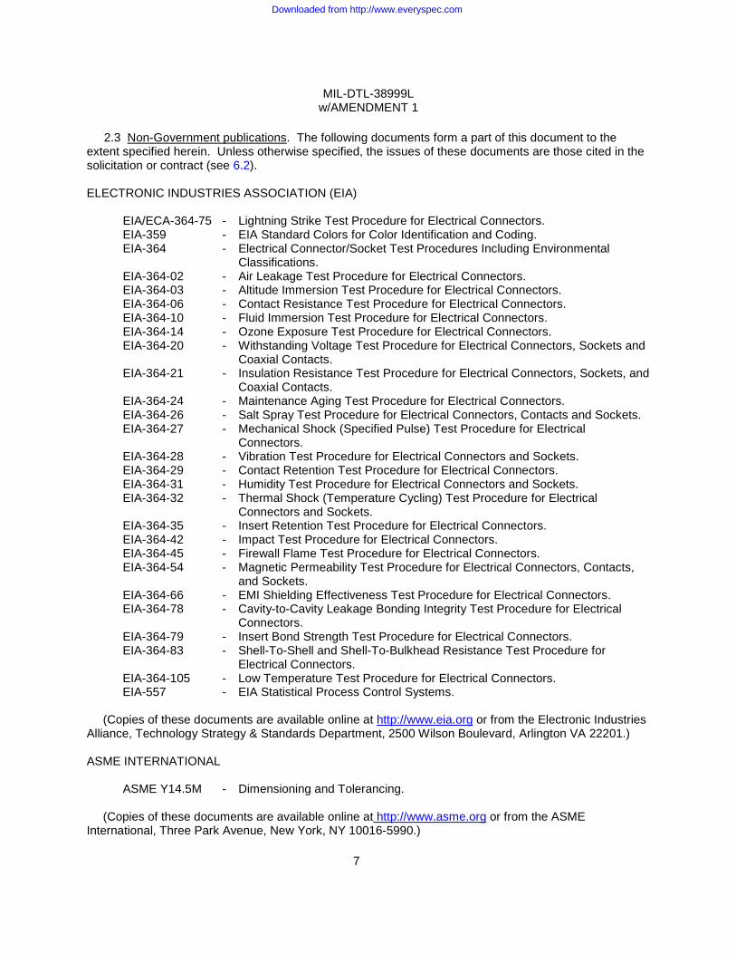
2.3 Non-Government publications. The following documents form a part of this document to the
extent specified herein. Unless otherwise specified, the issues of these documents are those cited in the solicitation or contract (see 6.2). ELECTRONIC INDUSTRIES ASSOCIATION (EIA)
EIA/ECA-364-75 - Lightning Strike Test Procedure for Electrical Connectors. EIA-359 - EIA Standard Colors for Color Identification and Coding. EIA-364 - Electrical Connector/Socket Test Procedures Including Environmental
Classifications. EIA-364-02 - Air Leakage Test Procedure for Electrical Connectors. EIA-364-03 - Altitude Immersion Test Procedure for Electrical Connectors. EIA-364-06 - Contact Resistance Test Procedure for Electrical Connectors. EIA-364-10 - Fluid Immersion Test Procedure for Electrical Connectors. EIA-364-14 - Ozone Exposure Test Procedure for Electrical Connectors. EIA-364-20 - Withstanding Voltage Test Procedure for Electrical Connectors, Sockets and
Coaxial Contacts. EIA-364-21 - Insulation Resistance Test Procedure for Electrical Connectors, Sockets, and
Coaxial Contacts. EIA-364-24 - Maintenance Aging Test Procedure for Electrical Connectors. EIA-364-26 - Salt Spray Test Procedure for Electrical Connectors, Contacts and Sockets. EIA-364-27 - Mechanical Shock (Specified Pulse) Test Procedure for Electrical
Connectors. EIA-364-28 - Vibration Test Procedure for Electrical Connectors and Sockets. EIA-364-29 - Contact Retention Test Procedure for Electrical Connectors. EIA-364-31 - Humidity Test Procedure for Electrical Connectors and Sockets. EIA-364-32 - Thermal Shock (Temperature Cycling) Test Procedure for Electrical
Connectors and Sockets. EIA-364-35 - Insert Retention Test Procedure for Electrical Connectors. EIA-364-42 - Impact Test Procedure for Electrical Connectors. EIA-364-45 - Firewall Flame Test Procedure for Electrical Connectors. EIA-364-54 - Magnetic Permeability Test Procedure for Electrical Connectors, Contacts,
and Sockets. EIA-364-66 - EMI Shielding Effectiveness Test Procedure for Electrical Connectors. EIA-364-78 - Cavity-to-Cavity Leakage Bonding Integrity Test Procedure for Electrical
Connectors. EIA-364-79 - Insert Bond Strength Test Procedure for Electrical Connectors. EIA-364-83 - Shell-To-Shell and Shell-To-Bulkhead Resistance Test Procedure for
Electrical Connectors. EIA-364-105 - Low Temperature Test Procedure for Electrical Connectors. EIA-557 - EIA Statistical Process Control Systems.
(Copies of these documents are available online at http://www.eia.org or from the Electronic Industries
Alliance, Technology Strategy & Standards Department, 2500 Wilson Boulevard, Arlington VA 22201.) ASME INTERNATIONAL
ASME Y14.5M - Dimensioning and Tolerancing.
(Copies of these documents are available online at http://www.asme.org or from the ASME International, Three Park Avenue, New York, NY 10016-5990.)
Downloaded from http://www.everyspec.com
MIL-DTL-38999L w/AMENDMENT 1
8
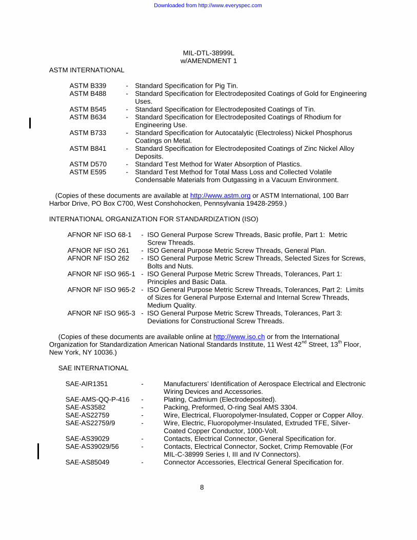
ASTM INTERNATIONAL
ASTM B339 - Standard Specification for Pig Tin. ASTM B488 - Standard Specification for Electrodeposited Coatings of Gold for Engineering
Uses. ASTM B545 - Standard Specification for Electrodeposited Coatings of Tin. ASTM B634 - Standard Specification for Electrodeposited Coatings of Rhodium for
Engineering Use. ASTM B733 - Standard Specification for Autocatalytic (Electroless) Nickel Phosphorus
Coatings on Metal. ASTM B841 - Standard Specification for Electrodeposited Coatings of Zinc Nickel Alloy
Deposits. ASTM D570 - Standard Test Method for Water Absorption of Plastics. ASTM E595 - Standard Test Method for Total Mass Loss and Collected Volatile
Condensable Materials from Outgassing in a Vacuum Environment.
(Copies of these documents are available at http://www.astm.org or ASTM International, 100 Barr Harbor Drive, PO Box C700, West Conshohocken, Pennsylvania 19428-2959.) INTERNATIONAL ORGANIZATION FOR STANDARDIZATION (ISO)
AFNOR NF ISO 68-1 - ISO General Purpose Screw Threads, Basic profile, Part 1: Metric Screw Threads.
AFNOR NF ISO 261 - ISO General Purpose Metric Screw Threads, General Plan. AFNOR NF ISO 262 - ISO General Purpose Metric Screw Threads, Selected Sizes for Screws,
Bolts and Nuts. AFNOR NF ISO 965-1 - ISO General Purpose Metric Screw Threads, Tolerances, Part 1:
Principles and Basic Data. AFNOR NF ISO 965-2 - ISO General Purpose Metric Screw Threads, Tolerances, Part 2: Limits
of Sizes for General Purpose External and Internal Screw Threads, Medium Quality.
AFNOR NF ISO 965-3 - ISO General Purpose Metric Screw Threads, Tolerances, Part 3: Deviations for Constructional Screw Threads.
(Copies of these documents are available online at http://www.iso.ch or from the International
Organization for Standardization American National Standards Institute, 11 West 42nd Street, 13th Floor, New York, NY 10036.)
SAE INTERNATIONAL
SAE-AIR1351 - Manufacturers’ Identification of Aerospace Electrical and Electronic Wiring Devices and Accessories.
SAE-AMS-QQ-P-416 - Plating, Cadmium (Electrodeposited). SAE-AS3582 - Packing, Preformed, O-ring Seal AMS 3304. SAE-AS22759 - Wire, Electrical, Fluoropolymer-Insulated, Copper or Copper Alloy. SAE-AS22759/9 - Wire, Electric, Fluoropolymer-Insulated, Extruded TFE, Silver-
Coated Copper Conductor, 1000-Volt. SAE-AS39029 - Contacts, Electrical Connector, General Specification for. SAE-AS39029/56 - Contacts, Electrical Connector, Socket, Crimp Removable (For
MIL-C-38999 Series I, III and IV Connectors). SAE-AS85049 - Connector Accessories, Electrical General Specification for.
Downloaded from http://www.everyspec.com

MIL-DTL-38999L w/AMENDMENT 1
9
SAE-AS85049/80 - Connector Accessories, Electrical, Dummy Contact, Sizes 12 and
8, Category 7 (for MIL-DTL-38999 Connectors). SAE-AS85049/81 - Connector Accessories, Electrical, Seal Plug, Size 10, Category 7
(for MIL-DTL-38999 Connectors). SAE-AS85049/103 - Connectors, Accessories, Composite, RFI/EMI, Electrical, Strain
Relief, Straight, Self-locking, Category 3C (for MIL-DTL-38999 Series III and IV Connectors) – FSC 5935.
(Copies of these documents are available at http://www.sae.org or SAE World Headquarters, 400
Commonwealth Drive, Warrendale, PA 15096-0001.)
2.4 Order of precedence. Unless otherwise noted herein or in the contract, in the event of a conflict between the text of this document and the references cited herein (except for related specification sheets), the text of this document takes precedence. Nothing in this document, however, supersedes applicable laws and regulations unless a specific exemption has been obtained.
3. REQUIREMENTS
3.1 Specification sheets. The individual item requirements shall be as specified herein and in accordance with the applicable specification sheet. In the event of any conflict between the requirements of this specification and the specification sheet, the latter shall govern.
3.2 Qualification. Connectors and accessories furnished under this specification shall be products
that are authorized by the qualifying activity for listing on the applicable qualified products list before contract award (see 4.3 and 6.3).
3.2.1 Qualified Products List (QPL) system. The manufacturer shall establish and maintain a quality system that allows its parts that are covered by this specification to be listed on the QPL. Requirements for this system are specified in MIL-STD-790. In addition, the manufacturer shall establish a Statistical Process Control (SPC) system that meets the requirements of EIA-557.
3.3 Materials.
3.3.1 Critical interface materials. Materials shall be as specified herein. If materials other than those specified are used, the contractor shall certify to the qualifying activity that the substitute material enables the connectors to meet the requirements of this specification. Acceptance or approval of any constituent material shall not be construed as a guaranty of acceptance of the product. When a definite material is not specified, a material shall be used which will enable the connector to meet the requirements of this specification.
3.3.1.1 Metals. Metals shall be of a corrosion-resistant type or shall be plated or treated to resist corrosion.
3.3.1.2 Dissimilar metals and compatible couples. When dissimilar metals are used in intimate contact with each other, protection against galvanic corrosion shall be provided. The use of dissimilar metals in contact, which tend toward active galvanic corrosion (particularly brass, copper, or steel used in contact with aluminum or an aluminum alloy) is not acceptable. However, metal plating of dissimilar base metals to provide similar or suitable abutting surfaces is permitted. The use of dissimilar metals separated by a suitable insulating material is also permitted. Dissimilar metals and compatible couples are specified in MIL-STD-889.
Downloaded from http://www.everyspec.com
MIL-DTL-38999L w/AMENDMENT 1
10
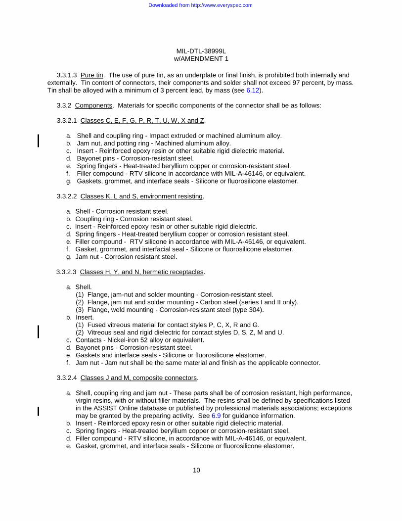
3.3.1.3 Pure tin. The use of pure tin, as an underplate or final finish, is prohibited both internally and
externally. Tin content of connectors, their components and solder shall not exceed 97 percent, by mass. Tin shall be alloyed with a minimum of 3 percent lead, by mass (see 6.12).
3.3.2 Components. Materials for specific components of the connector shall be as follows:
3.3.2.1 Classes C, E, F, G, P, R, T, U, W, X and Z.
a. Shell and coupling ring - Impact extruded or machined aluminum alloy. b. Jam nut, and potting ring - Machined aluminum alloy. c. Insert - Reinforced epoxy resin or other suitable rigid dielectric material. d. Bayonet pins - Corrosion-resistant steel. e. Spring fingers - Heat-treated beryllium copper or corrosion-resistant steel. f. Filler compound - RTV silicone in accordance with MIL-A-46146, or equivalent. g. Gaskets, grommet, and interface seals - Silicone or fluorosilicone elastomer.
3.3.2.2 Classes K, L and S, environment resisting.
a. Shell - Corrosion resistant steel. b. Coupling ring - Corrosion resistant steel. c. Insert - Reinforced epoxy resin or other suitable rigid dielectric. d. Spring fingers - Heat-treated beryllium copper or corrosion resistant steel. e. Filler compound - RTV silicone in accordance with MIL-A-46146, or equivalent. f. Gasket, grommet, and interfacial seal - Silicone or fluorosilicone elastomer. g. Jam nut - Corrosion resistant steel.
3.3.2.3 Classes H, Y, and N, hermetic receptacles.
a. Shell. (1) Flange, jam-nut and solder mounting - Corrosion-resistant steel. (2) Flange, jam nut and solder mounting - Carbon steel (series I and II only). (3) Flange, weld mounting - Corrosion-resistant steel (type 304).
b. Insert. (1) Fused vitreous material for contact styles P, C, X, R and G. (2) Vitreous seal and rigid dielectric for contact styles D, S, Z, M and U.
c. Contacts - Nickel-iron 52 alloy or equivalent. d. Bayonet pins - Corrosion-resistant steel. e. Gaskets and interface seals - Silicone or fluorosilicone elastomer. f. Jam nut - Jam nut shall be the same material and finish as the applicable connector.
3.3.2.4 Classes J and M, composite connectors.
a. Shell, coupling ring and jam nut - These parts shall be of corrosion resistant, high performance,
virgin resins, with or without filler materials. The resins shall be defined by specifications listed in the ASSIST Online database or published by professional materials associations; exceptions may be granted by the preparing activity. See 6.9 for guidance information.
b. Insert - Reinforced epoxy resin or other suitable rigid dielectric material. c. Spring fingers - Heat-treated beryllium copper or corrosion-resistant steel. d. Filler compound - RTV silicone, in accordance with MIL-A-46146, or equivalent. e. Gasket, grommet, and interface seals - Silicone or fluorosilicone elastomer.
Downloaded from http://www.everyspec.com

MIL-DTL-38999L w/AMENDMENT 1
11
3.3.3 Fungus resistance. Materials used in the construction of these connectors shall be fungus inert
(see 4.2.2). 3.3.4 Magnetic permeability. Not applicable to finish D of series I and II. The relative permeability of
the wired, assembled, and fully mated connector assembly shall be less than 2.0µ when measured in accordance with 4.5.48.
3.3.5 Recycled, recovered, or environmentally preferable materials. Recycled, recovered, or environmentally preferable materials should be used to the maximum extent possible, provided that the material meets or exceeds the operational and maintenance requirements, and promotes economically advantageous life cycle costs.
3.3.6 Plating.
3.3.6.1 Contacts (hermetic receptacles). The following is applicable to contacts with contact designators P, S, X, Z, C, D, R, M, G and U. Contacts shall be gold-plated to a minimum thickness of .000050 inch (0.00127 mm) in accordance with ASTM B488 over a suitable underplate. Silver underplate shall not be used. Rhodium contacts (designators R and M) shall be a minimum of .000050 inch (0.00127 mm) rhodium plate over a minimum of .000150 inch (0.004 mm) nickel plate. Heavy gold contacts (designators G and U) shall have a minimum plating thickness of .000100 inch (0.00254 mm) .000100 inch (0.00254 mm) gold plate in accordance with ASTM B488 over a minimum of .000050 inch (0.00127 mm) nickel plate. Wire marks on the back of the contact around the "nonfunctional" outside diameter of the wire well caused by electrical contact for plating are permissible.
3.3.6.2 Rhodium plated contacts (crimp contact designators R and M). Contact plating shall be as
specified in SAE-AS39029. Plating thickness shall be a minimum of .000050 inch (0.00127 mm) rhodium plate in accordance with ASTM B634 over a minimum of .000150 inch (0.004 mm) nickel plate.
3.3.6.3 Heavy gold plated contacts (crimp contact designators G and U). Contact plating shall be as specified in SAE-AS39029. Plating thickness shall be a minimum of .000100 inch (0.00254 mm) gold plate in accordance with ASTM B488, Type II, Code C, over a minimum of .000050 inch (0.00127 mm) nickel plate.
3.3.6.4 Shells and accessory hardware. Unless otherwise specified, the finish on shells and
accessory hardware shall be in accordance with the following designations: Series I and II finishes:
A - Nickel plate a minimum of .0002 inch (0.005 mm) followed by cadmium plate .0001 inch
(0.003 mm) minimum in accordance with SAE-AMS-QQ-P-416, type II. A preliminary plate of other metal is permissible. The final finish shall be electrically conductive and shall be silver to light iridescent yellow in color. Finish A is inactive for new design.
B - Olive drab cadmium plate in accordance with SAE-AMS-QQ-P-416 over a suitable
underplate. Final finish shall be electrically conductive. C - Hard, anodic, nonconductive in accordance with MIL-A-8625, type III, .0008 inch (0.020
mm) minimum thickness. D - Fused tin plate in accordance with ASTM B545 or ASTM B339. The tin shall be
reflowed to promote solderability. Tin application process shall inhibit tin whisker growth.
Downloaded from http://www.everyspec.com
MIL-DTL-38999L w/AMENDMENT 1
12
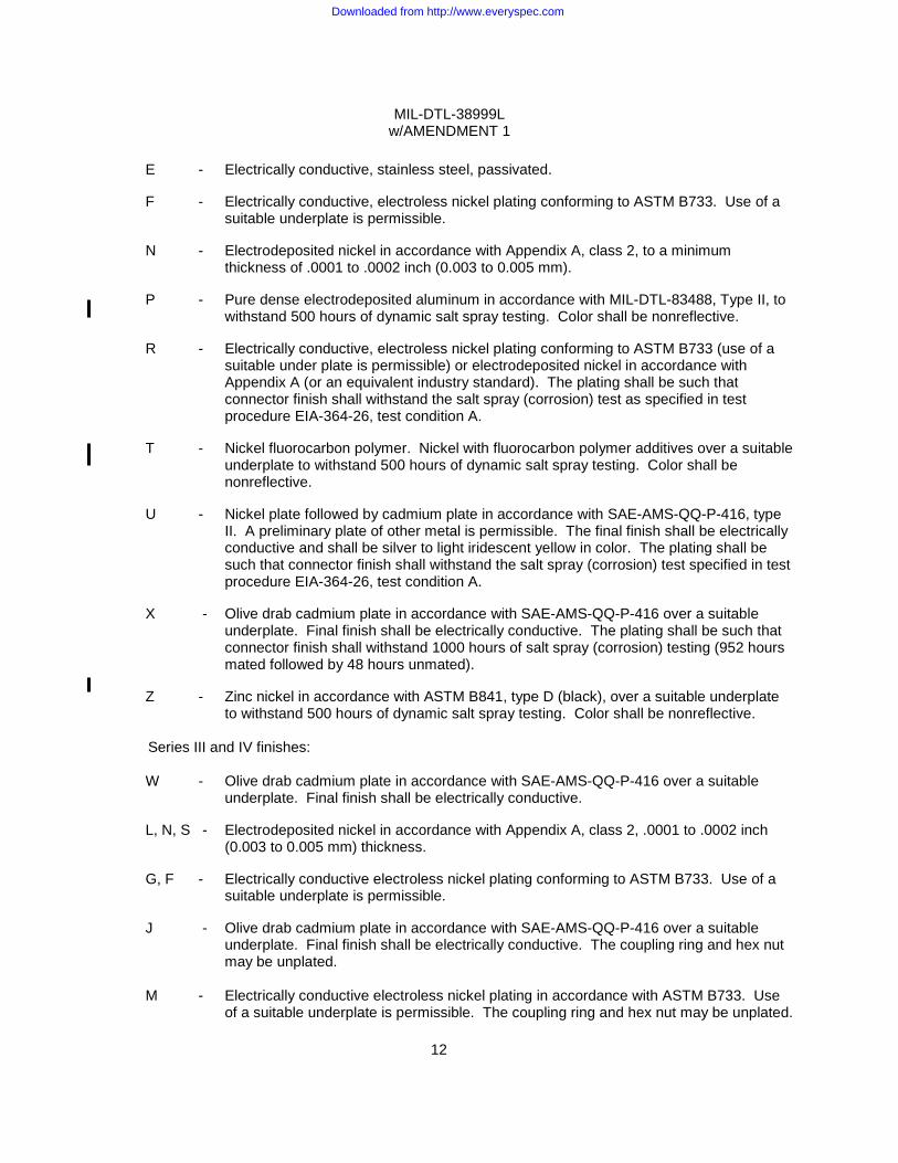
E - Electrically conductive, stainless steel, passivated. F - Electrically conductive, electroless nickel plating conforming to ASTM B733. Use of a
suitable underplate is permissible. N - Electrodeposited nickel in accordance with Appendix A, class 2, to a minimum
thickness of .0001 to .0002 inch (0.003 to 0.005 mm). P - Pure dense electrodeposited aluminum in accordance with MIL-DTL-83488, Type II, to
withstand 500 hours of dynamic salt spray testing. Color shall be nonreflective.
R - Electrically conductive, electroless nickel plating conforming to ASTM B733 (use of a suitable under plate is permissible) or electrodeposited nickel in accordance with Appendix A (or an equivalent industry standard). The plating shall be such that connector finish shall withstand the salt spray (corrosion) test as specified in test procedure EIA-364-26, test condition A.
T - Nickel fluorocarbon polymer. Nickel with fluorocarbon polymer additives over a suitable
underplate to withstand 500 hours of dynamic salt spray testing. Color shall be nonreflective.
U - Nickel plate followed by cadmium plate in accordance with SAE-AMS-QQ-P-416, type
II. A preliminary plate of other metal is permissible. The final finish shall be electrically conductive and shall be silver to light iridescent yellow in color. The plating shall be such that connector finish shall withstand the salt spray (corrosion) test specified in test procedure EIA-364-26, test condition A.
X - Olive drab cadmium plate in accordance with SAE-AMS-QQ-P-416 over a suitable
underplate. Final finish shall be electrically conductive. The plating shall be such that connector finish shall withstand 1000 hours of salt spray (corrosion) testing (952 hours mated followed by 48 hours unmated).
Z - Zinc nickel in accordance with ASTM B841, type D (black), over a suitable underplate
to withstand 500 hours of dynamic salt spray testing. Color shall be nonreflective. Series III and IV finishes:
W - Olive drab cadmium plate in accordance with SAE-AMS-QQ-P-416 over a suitable
underplate. Final finish shall be electrically conductive.
L, N, S - Electrodeposited nickel in accordance with Appendix A, class 2, .0001 to .0002 inch (0.003 to 0.005 mm) thickness.
G, F - Electrically conductive electroless nickel plating conforming to ASTM B733. Use of a
suitable underplate is permissible. J - Olive drab cadmium plate in accordance with SAE-AMS-QQ-P-416 over a suitable
underplate. Final finish shall be electrically conductive. The coupling ring and hex nut may be unplated.
M - Electrically conductive electroless nickel plating in accordance with ASTM B733. Use
of a suitable underplate is permissible. The coupling ring and hex nut may be unplated.
Downloaded from http://www.everyspec.com
MIL-DTL-38999L w/AMENDMENT 1
13
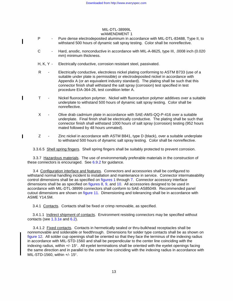
P - Pure dense electrodeposited aluminum in accordance with MIL-DTL-83488, Type II, to withstand 500 hours of dynamic salt spray testing. Color shall be nonreflective.
C - Hard, anodic, nonconductive in accordance with MIL-A-8625, type III, .0008 inch (0.020
mm) minimum thickness.
H, K, Y - Electrically conductive, corrosion resistant steel, passivated. R - Electrically conductive, electroless nickel plating conforming to ASTM B733 (use of a
suitable under plate is permissible) or electrodeposited nickel in accordance with Appendix A (or an equivalent industry standard). The plating shall be such that this connector finish shall withstand the salt spray (corrosion) test specified in test procedure EIA-364-26, test condition letter A.
T - Nickel fluorocarbon polymer. Nickel with fluorocarbon polymer additives over a suitable
underplate to withstand 500 hours of dynamic salt spray testing. Color shall be nonreflective.
X - Olive drab cadmium plate in accordance with SAE-AMS-QQ-P-416 over a suitable
underplate. Final finish shall be electrically conductive. The plating shall be such that connector finish shall withstand 1000 hours of salt spray (corrosion) testing (952 hours mated followed by 48 hours unmated).
Z - Zinc nickel in accordance with ASTM B841, type D (black), over a suitable underplate
to withstand 500 hours of dynamic salt spray testing. Color shall be nonreflective.
3.3.6.5 Shell spring fingers. Shell spring fingers shall be suitably protected to prevent corrosion.
3.3.7 Hazardous materials. The use of environmentally preferable materials in the construction of these connectors is encouraged. See 6.9.2 for guidance.
3.4 Configuration interface and features. Connectors and accessories shall be configured to withstand normal handling incident to installation and maintenance in service. Connector intermateability control dimensions shall be as specified on figures 1 through 7. Connector accessory interface dimensions shall be as specified on figures 8, 9, and 10. All accessories designed to be used in accordance with MIL-DTL-38999 connectors shall conform to SAE-AS85049. Recommended panel cutout dimensions are shown on figure 11. Dimensioning and tolerancing shall be in accordance with ASME Y14.5M.
3.4.1 Contacts. Contacts shall be fixed or crimp removable, as specified.
3.4.1.1 Indirect shipment of contacts. Environment resisting connectors may be specified without contacts (see 1.3.1e and 6.2).
3.4.1.2 Fixed contacts. Contacts in hermetically sealed or thru-bulkhead receptacles shall be nonremovable and solderable or feedthrough. Dimensions for solder type contacts shall be as shown on figure 12. All solder cup openings shall be oriented so that they face the terminus of the indexing radius in accordance with MIL-STD-1560 and shall be perpendicular to the center line coinciding with the indexing radius, within +/- 15°. All eyelet terminations shall be oriented with the eyelet openings facing the same direction and in parallel to the center line coinciding with the indexing radius in accordance with MIL-STD-1560, within +/- 15°.
Downloaded from http://www.everyspec.com

MIL-DTL-38999L w/AMENDMENT 1
14
3.4.1.3 Crimp removable contacts. Crimp removable contacts may be used with all environment
resisting classes of connectors. Crimp contacts shall be qualified products in accordance with SAE-AS39029 (see 6.5). The quantity of crimp contacts to be supplied with each connector unit package shall consist of a full complement of contacts plus 1 spare contact for each size used in the arrangement utilizing 26 contacts or less. For arrangements utilizing more than 26 contacts, 2 spare contacts of each size used in the arrangement shall be supplied. Spare Coax and Twinax contacts are not required.
3.4.1.4 Contact arrangement. Contact arrangement shall be in accordance with MIL-STD-1560. Except for hermetic assemblies, the engaging end of the pin contact in assembled connectors shall be located within .024 inch (0.61 mm) diameter of true position and the engaging end of socket contacts in assembled connectors shall be located within .015 inch (0.38 mm) diameter of true position. For hermetic connectors, the engaging end of pin and socket contacts shall be located within .004 inch (0.10 mm) diameter of true position. Test voltages for service ratings shall be as specified in table I.
TABLE I. Test voltages, ac rms, 60 Hz.
Altitude
Service rating M Service rating N Service rating I Service rating II Mated Unmated Mated Unmated Mated Unmated Mated Unmated
Sea level 1300 1300 1000 1000 1800 1800 2300 2300 50,000 feet 800 550 600 400 1000 600 1000 800 70,000 feet 800 350 600 260 1000 400 1000 500 100,000 feet 800 200 600 200 1000 200 1000 200
3.4.1.5 Installing and removal tools. Both MIL-I-81969/8 and MIL-I-81969/14 tools shall be utilized to
properly assemble and disassemble the pin and socket contacts into their connector inserts. One MIL-I-81969/14 tool for each contact size shall be enclosed in the unit package. For indirect shipments, connectors may be specified without installation and removal tools (see 6.2).
3.4.1.6 Dust caps/containers. Dust caps shall be placed on the mating end of each connector. For
RFI connectors, dust caps must be assembled externally over the coupling ring. Hermetic connectors require caps on both ends. In lieu of dust caps on both ends, hermetic receptacles may be packaged in rigid or semi-rigid containers designed to prevent damage to the termination end of the connector.
3.4.2 Insert interface.
3.4.2.1 Environment resisting classes. The entire insert and wire sealing or wire supporting member of the environment resisting assemblies shall be essentially one integral part, configured to provide suitable sealing and support (except box mount connectors) around the wires and to be nonremovable. The rigid dielectric shall be one molded piece or no more than two pieces bonded so as to form essentially one integral piece. The configuration shall be such as to permit the removal and replacement of individual contacts into their connector inserts with either MIL-I-81969/8 or MIL-I-81969/14 installation/removal tools. The contact locking device shall be contained in the rigid dielectric insert and shall so retain the contacts as to meet the contact retention requirements of this specification. Inserts shall be secured to prevent rotation. All pin contact inserts shall have a resilient interface seal bonded to the front face in accordance with the applicable standards. Socket entry holes and pin "donut" rings shall conform to the requirements on figures 13, 14 and 15. Wire sealing for size 8 cavities may be accomplished by the use of a separate resilient bushing. If separate resilient bushings are required, they shall be furnished with the connector.
Downloaded from http://www.everyspec.com
MIL-DTL-38999L w/AMENDMENT 1
15
3.4.2.2 Hermetic receptacles. Vitreous material shall be used for fusing to metal to insulate and seal
contacts. The insert member for contact styles S and Z shall be a two-piece construction consisting of a reinforced rigid dielectric socket support member bonded to the face of the vitreous insert and mechanically retained in the shell. Socket insert entry holes shall conform to the requirements depicted on figure 12. All pin contact inserts shall have a resilient interface seal bonded to the front face of the vitreous insert in accordance with the applicable standards. Pin "donut" rings shall conform to the requirements as specified on figure 13, figure 14 and figure 15.
3.4.3 Sealing.
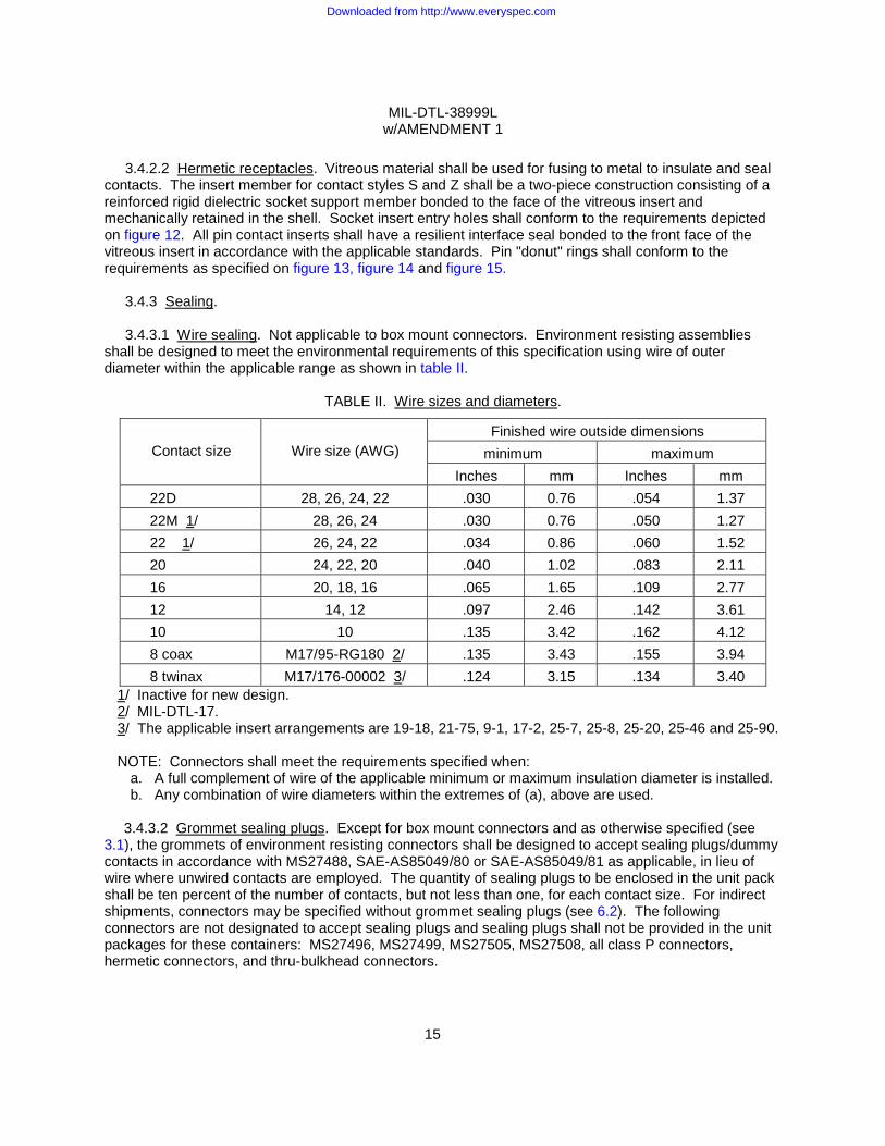
3.4.3.1 Wire sealing. Not applicable to box mount connectors. Environment resisting assemblies shall be designed to meet the environmental requirements of this specification using wire of outer diameter within the applicable range as shown in table II.
TABLE II. Wire sizes and diameters.
Contact size
Wire size (AWG)
Finished wire outside dimensions minimum maximum
Inches mm Inches mm 22D 28, 26, 24, 22 .030 0.76 .054 1.37 22M 1/ 28, 26, 24 .030 0.76 .050 1.27 22 1/ 26, 24, 22 .034 0.86 .060 1.52 20 24, 22, 20 .040 1.02 .083 2.11 16 20, 18, 16 .065 1.65 .109 2.77 12 14, 12 .097 2.46 .142 3.61 10 10 .135 3.42 .162 4.12 8 coax M17/95-RG180 2/ .135 3.43 .155 3.94 8 twinax M17/176-00002 3/ .124 3.15 .134 3.40
1/ Inactive for new design. 2/ MIL-DTL-17. 3/ The applicable insert arrangements are 19-18, 21-75, 9-1, 17-2, 25-7, 25-8, 25-20, 25-46 and 25-90.
NOTE: Connectors shall meet the requirements specified when:
a. A full complement of wire of the applicable minimum or maximum insulation diameter is installed. b. Any combination of wire diameters within the extremes of (a), above are used.
3.4.3.2 Grommet sealing plugs. Except for box mount connectors and as otherwise specified (see
3.1), the grommets of environment resisting connectors shall be designed to accept sealing plugs/dummy contacts in accordance with MS27488, SAE-AS85049/80 or SAE-AS85049/81 as applicable, in lieu of wire where unwired contacts are employed. The quantity of sealing plugs to be enclosed in the unit pack shall be ten percent of the number of contacts, but not less than one, for each contact size. For indirect shipments, connectors may be specified without grommet sealing plugs (see 6.2). The following connectors are not designated to accept sealing plugs and sealing plugs shall not be provided in the unit packages for these containers: MS27496, MS27499, MS27505, MS27508, all class P connectors, hermetic connectors, and thru-bulkhead connectors.
Downloaded from http://www.everyspec.com

MIL-DTL-38999L w/AMENDMENT 1
16
3.4.3.3 Mating seal. Plugs and receptacles with pin inserts shall have a resilient face with individual
pin barriers (see figure 13, figure 14 and figure 15). The pin barrier projections shall seal in their respective lead-in chambers of the hard face socket insert. The resilient interfacial seal shall provide individual contact seals in the mated condition to ensure circuit isolation between each contact and contact to shell. The receptacles of series I, II, and III shall be provided with a peripheral seal. The plugs of series IV shall incorporate an O-ring peripheral seal.
3.4.4 Shell. Shells, including mounting flanges, shall be of one-piece construction and shall be designed to retain their inserts in one position, both axially and with respect to rotation, by mechanical means. Adhesive may be used as a supplementary retention means for environment resisting connectors. Each plug and receptacle connector shall have at least one blue color band in accordance with EIA-359, indicating a rear release contact retention system. The blue color band shall be located so that it is readily visible to any person servicing a mounted connector. Hermetic receptacles do not require a blue color band.
3.4.4.1 Spring fingers. Not applicable to class C or finish C. All series I and III plugs shall have spring fingers. All series II and IV plugs noted "EMI grounding" (see 3.1) shall have spring fingers. Spring fingers shall be designed to make electrical contact with the mating shell without interfering with proper engagement. The springs shall be retained about the shell periphery. Minimum engagement of spring fingers shall be .040 (1.02 mm) prior to contact engagement for series I, III, and IV, and shall be after contact engagement for series II. Gold plating shall not be permitted on the spring fingers in connectors with cadmium plated shells.
3.4.4.2 Jam nut mounting receptacles. Jam nut mounting receptacles shall be provided with a
mounting nut MS3186 for series I and II, and MIL-DTL-38999/28 for series III and IV, all with provisions for locking, and an O-ring in accordance with SAE-AS3582.
3.4.5 Screw threads. Screw threads shall conform to FED-STD-H28, MIL-S-7742, AFNOR NF ISO 68-1, AFNOR NF ISO 261, AFNOR NF ISO 262, AFNOR NF ISO 965-1, AFNOR NF ISO 965-2, and AFNOR NF ISO 965-3 as applicable. Threads shall be checked using ring or plug gauges. Slight out-of-roundness beyond the specified tolerances is acceptable if threads can accept the gauges without forcing.
3.4.6 Coupling. Connectors shall be coupled to counterpart connectors by means of a bayonet mechanism for series I and II, a triple start thread mechanism for series III and a breech mechanism for series IV. The mechanism shall include a means of maintaining the mated connector in full engagement. The coupling ring shall be knurled or fluted to facilitate coupling and shall be captivated. The coupling rings of all connectors shall have a blue color band in accordance with EIA-359, indicating a rear release contact retention system. Coupling rings of series I and II connectors and accessories shall be permanently attached. The end surfaces of all bayonet pins shall be of contrasting blue (or orange for Series I and II) color to the shell finish.
3.4.6.1 Ease of coupling. Counterpart connectors of any arrangement shall be capable of being fully coupled and uncoupled in a normal and accessible location without the use of tools.
3.4.6.2 Locking.
3.4.6.2.1 Series I and II. For series I and II, a detent shall be provided in the coupling mechanism so that an audible click is evident when proper coupling is accomplished. Provisions shall be made for visual determination that proper and full coupling has been achieved by ensuring that the bayonet pins are completely visible in the inspection hole. The top of the bayonet pins shall be colored a blue or orange contrasting color for ease of visual identification in the inspection hole.
Downloaded from http://www.everyspec.com
MIL-DTL-38999L w/AMENDMENT 1
17
3.4.6.2.2 Series III. For series III, complete coupling shall be accomplished by approximately 360°
clockwise rotation of the coupling nut and shall provide shell-to-shell bottoming when tested in accordance with 4.5.23.2.3. Mated connectors, when vibrated sinusoidally, shall not display any resonance greater than 300 Hz. An anti-decoupling device shall be provided to maintain complete coupling. A solid red band, uniform in color, shall be located on the receptacle so as to be visible when unmated and fully covered when completely mated. The band shall remain permanent after exposure to all tests specified in table XIV herein.
3.4.6.2.3 Series IV. Complete coupling shall be accomplished by approximately 90° clockwise
rotation of the coupling ring. The coupling ring shall incorporate a positive detent action at both the ready-to-mate and the mated positions providing both an audible and tactile indication of complete mating. A solid red band, uniform in color, shall be located on the plug so as to be fully visible when the coupling ring is in the ready-to-mate position, and fully covered when the coupling ring is in the completely mated position. Coverage of the red band during mating without the action of the audible and tactile indicators constitutes an unmated connector. The band shall remain permanent after exposure to all tests specified in table XIV herein.
3.4.6.3 Polarization of connector shells. Polarization of connector shells shall be accomplished by means of integral keys and suitable matching keyways on the counterpart. Polarization shall be accomplished before initial engagement of the coupling ring. During axial engagement, pins shall not touch sockets or the insert face until polarization has been achieved.
3.4.6.3.1 Alternates. Shells shall also be supplied with the keys (or keyways) rotated from the normal as specified on figure 5, figure 6, and figure 7.
3.4.6.4 Lubrication. With the exception of class P of series III and IV, bayonet coupling ramps, spring washers, the breech mechanism on series IV, and the coupling threads of series III connectors may be coated with a suitable lubricant. Lubricants shall be non-flaking and galvanically compatible, and shall not migrate into threaded areas. Rear accessory threads of all connectors and receptacle coupling areas shall not be lubricated.
3.4.6.5 Pin-to-pin mating prevention. Applicable to series I, III and IV.
3.4.6.5.1 Series I and III. Series I and III connectors shall be designed such that pin-to-pin contact (electrical or physical) is not possible in the event that a plug with pin contacts is inadvertently mated with a receptacle with pin contacts.
3.4.6.5.2 Series IV. Series IV connectors shall be provided with key and keyway widths arranged so as to prevent a plug with pin contacts from being mated with a receptacle with pin contacts.
3.4.7 Cavity fill. Environment resisting classes only. If the rear grommet design does not allow for intimate contact between it and the complete inner perimeter of the shell, any resulting cavity between the insert and the shell shall be filled with RTV silicone conforming to MIL-A-46146, or equivalent. The silicone shall adhere to both the shell and the grommet.
3.5 Interchangeability. All connectors having the same Part or Identifying Number (PIN) shall be completely interchangeable with each other with respect to installation and performance.
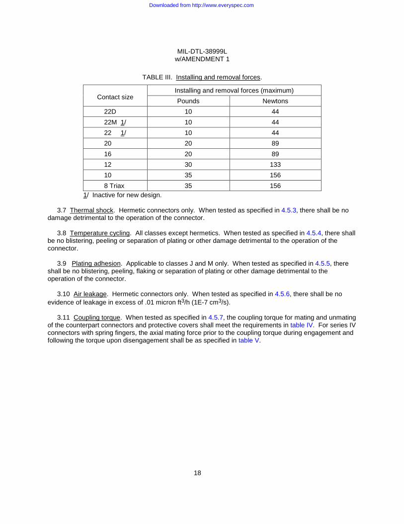
3.6 Maintenance aging. Not applicable to hermetic connectors. When tested as specified in 4.5.2, the contact installing and removal forces shall not exceed the requirements in table III.
Downloaded from http://www.everyspec.com
MIL-DTL-38999L w/AMENDMENT 1
18
TABLE III. Installing and removal forces.
Contact size Installing and removal forces (maximum) Pounds Newtons
22D 10 44 22M 1/ 10 44 22 1/ 10 44 20 20 89 16 20 89 12 30 133 10 35 156 8 Triax 35 156
1/ Inactive for new design. 3.7 Thermal shock. Hermetic connectors only. When tested as specified in 4.5.3, there shall be no
damage detrimental to the operation of the connector. 3.8 Temperature cycling. All classes except hermetics. When tested as specified in 4.5.4, there shall
be no blistering, peeling or separation of plating or other damage detrimental to the operation of the connector.
3.9 Plating adhesion. Applicable to classes J and M only. When tested as specified in 4.5.5, there shall be no blistering, peeling, flaking or separation of plating or other damage detrimental to the operation of the connector.
3.10 Air leakage. Hermetic connectors only. When tested as specified in 4.5.6, there shall be no evidence of leakage in excess of .01 micron ft3/h (1E-7 cm3/s).
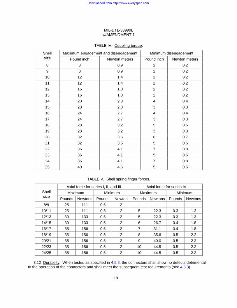
3.11 Coupling torque. When tested as specified in 4.5.7, the coupling torque for mating and unmating of the counterpart connectors and protective covers shall meet the requirements in table IV. For series IV connectors with spring fingers, the axial mating force prior to the coupling torque during engagement and following the torque upon disengagement shall be as specified in table V.
Downloaded from http://www.everyspec.com
MIL-DTL-38999L w/AMENDMENT 1
19
TABLE IV. Coupling torque.
Shell size
Maximum engagement and disengagement Minimum disengagement Pound inch Newton meters Pound inch Newton meters
8 8 0.9 2 0.2 9 8 0.9 2 0.2 10 12 1.4 2 0.2 11 12 1.4 2 0.2 12 16 1.8 2 0.2 13 16 1.8 2 0.2 14 20 2.3 4 0.4 15 20 2.3 3 0.3 16 24 2.7 4 0.4 17 24 2.7 3 0.3 18 28 3.2 5 0.6 19 28 3.2 3 0.3 20 32 3.6 6 0.7 21 32 3.6 5 0.6 22 36 4.1 7 0.8 23 36 4.1 5 0.6 24 36 4.1 7 0.8 25 40 4.6 5 0.6
TABLE V. Shell spring finger forces.
Shell size
Axial force for series I, II, and III Axial force for series IV Maximum Minimum Maximum Minimum
Pounds Newtons Pounds Newton Pounds Newtons Pounds Newtons 8/9 25 111 0.5 2 - - - -
10/11 25 111 0.5 2 5 22.3 0.3 1.3 12/13 30 133 0.5 2 5 22.3 0.3 1.3 14/15 30 133 0.5 2 6 26.7 0.4 1.8 16/17 35 156 0.5 2 7 31.1 0.4 1.8 18/19 35 156 0.5 2 8 35.6 0.5 2.2 20/21 35 156 0.5 2 9 40.0 0.5 2.2 22/23 35 156 0.5 2 10 44.5 0.5 2.2 24/25 35 156 0.5 2 10 44.5 0.5 2.2
3.12 Durability. When tested as specified in 4.5.8, the connectors shall show no defects detrimental
to the operation of the connectors and shall meet the subsequent test requirements (see 4.3.3).
Downloaded from http://www.everyspec.com
MIL-DTL-38999L w/AMENDMENT 1
20
3.13 Altitude immersion. All classes except hermetics, qualification only. When tested as specified in
4.5.9, the mated connector pair shall have a minimum insulation resistance as specified in 3.14.1 and dielectric withstanding voltage as specified in 3.15.
3.14 Insulation resistance.
3.14.1 Insulation resistance at ambient temperature. When tested as specified in 4.5.10.1, the insulation resistance between any pair of contacts and between any contact and the shell shall be greater than 5,000 megohms. Insulation resistance after altitude immersion shall be 1,000 megohms minimum. Insulation resistance after humidity shall be 100 megohms minimum.
3.14.2 Insulation resistance at elevated temperature. When tested as specified in 4.5.10.2, the insulation resistance between any pair of contacts and between any contact and the shell shall be greater than 1,000 megohms for environment resisting class connectors. Hermetic connectors shall be greater than 200 megohms.
3.15 Dielectric withstanding voltage. When tested as specified in 4.5.11.1 or 4.5.11.2, the maximum leakage current shall be 2 milliamperes, and there shall be no evidence of electric breakdown or flashover.
3.16 Insert retention. When tested as specified in 4.5.12, unmated connectors shall retain their
inserts in their proper location in the shell and there shall be no evidence of cracking, breaking, separation from the shell, or loosening of parts.
3.17 Salt spray (corrosion). When tested as specified in 4.5.13, unmated connectors shall show no lifting of plated coating or exposure of basis material under three power (3X) magnification which adversely affects performance when evaluated in accordance with EIA-364-26. For class J (initial qualification), inspect connectors after 500 hours salt spray for corrosion or exposure of underplate or basis material (inspection method optional), then return to chamber for the remaining required hours.
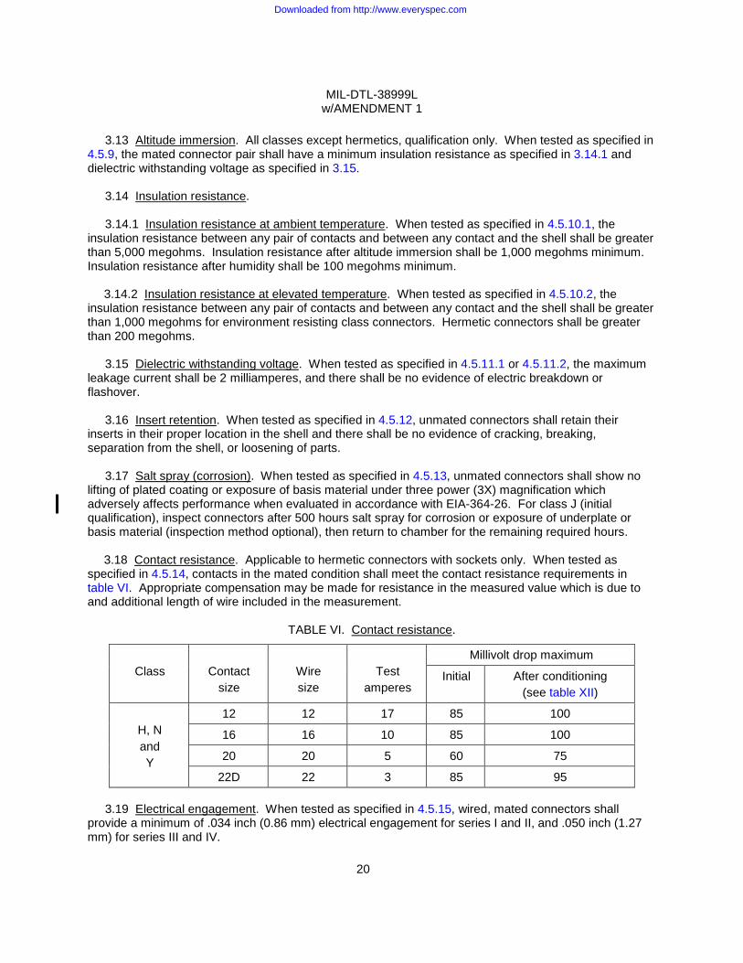
3.18 Contact resistance. Applicable to hermetic connectors with sockets only. When tested as specified in 4.5.14, contacts in the mated condition shall meet the contact resistance requirements in table VI. Appropriate compensation may be made for resistance in the measured value which is due to and additional length of wire included in the measurement.
TABLE VI. Contact resistance.
Class
Contact
size
Wire size
Test
amperes
Millivolt drop maximum
Initial After conditioning (see table XII)
H, N and Y
12 12 17 85 100
16 16 10 85 100
20 20 5 60 75
22D 22 3 85 95
3.19 Electrical engagement. When tested as specified in 4.5.15, wired, mated connectors shall provide a minimum of .034 inch (0.86 mm) electrical engagement for series I and II, and .050 inch (1.27 mm) for series III and IV.
Downloaded from http://www.everyspec.com
MIL-DTL-38999L w/AMENDMENT 1
21
3.20 External bending moment. When tested as specified in 4.5.16, connectors shall show no
evidence of damage detrimental to their normal operation, nor shall there be any interruption of electrical continuity.
3.21 Coupling pin strength. Applicable to series I and II only. When tested as specified in 4.5.17, bayonet coupling pins shall withstand a load of 50 +5, -0 pounds without displacement or perceptible loosening of coupling pins.
3.22 Gauge location. Using test gauges conforming to the requirements on figure 16, figure 17,
figure 18, and figure 19, the axial location of contacts shall be measured as specified in 4.5.18. Gauge location measurements shall fall within the range specified on figure 1, figure 2, figure 3, and figure 4.
3.23 Gauge retention. When tested as specified in 4.5.19, the test gauges conforming to the dimensions specified on figures 16, 20, and 21 shall be retained in the contact cavities of crimp contact connectors and the axial displacement of the test gauges while under load shall not exceed .012 inch (0.30 mm).
3.24 Contact retention. When tested as specified in 4.5.20, the axial displacement of the contact shall not exceed .012 inch (0.30 mm). No damage to contacts or inserts shall result.
3.25 Altitude-low temperature. When tested as specified in 4.5.21, the connectors shall meet the requirements of dielectric withstanding voltage at sea level specified in 3.15 and insulation resistance at ambient temperature specified in 3.14.1.
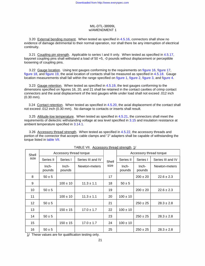
3.26 Accessory thread strength. When tested as specified in 4.5.22, the accessory threads and portion of the connector that accepts cable clamps and "J" adapters shall be capable of withstanding the torque listed in table VII.
TABLE VII. Accessory thread strength. 1/
Shell size
Accessory thread torque
Shell size
Accessory thread torque
Series II Series I Series III and IV Series II Series I Series III and IV
Inch-pounds
Inch-pounds
Newton-meters Inch-pounds
Inch-pounds
Newton-meters
8 50 ± 5 17 200 ± 20 22.6 ± 2.3
9 100 ± 10 11.3 ± 1.1 18 50 ± 5
10 50 ± 5 19 200 ± 20 22.6 ± 2.3
11 100 ± 10 11.3 ± 1.1 20 100 ± 10
12 50 ± 5 21 250 ± 25 28.3 ± 2.8
13 150 ± 15 17.0 ± 1.7 22 100 ± 10
14 50 ± 5 23 250 ± 25 28.3 ± 2.8
15 150 ± 15 17.0 ± 1.7 24 100 ± 10
16 50 ± 5 25 250 ± 25 28.3 ± 2.8 1/ These values are for qualification testing only.
Downloaded from http://www.everyspec.com

MIL-DTL-38999L w/AMENDMENT 1
22
3.27 Vibration. Applicable to initial qualification only. When tested as specified in 4.5.23, there shall
be no electrical discontinuity and there shall be no disengagement of the mated connectors, backing off of the coupling mechanism, evidence of cracking, breaking, or loosening of parts.
3.28 Shock. When tested as specified in 4.5.24, there shall be no electrical discontinuity and there shall be no disengagement of the mated connectors, evidence of cracking, breaking, or loosening of parts.
3.29 Shell-to-shell conductivity. Not applicable to class C and finish C. When tested as specified in 4.5.25, probes shall not puncture or otherwise damage the connector finish and the maximum measured potential drop across assemblies shall be as follows:
a. Series I and II with spring fingers:
(1) Finishes A, B, P, T, U, X and Z - 2.5 millivolts. (2) Stainless steel or a connector having half of the mating part stainless steel – 50.0 millivolts. (3) Finishes F, N and R – 1.0 millivolt.
b. Series II and IV without spring fingers – 200.0 millivolts.
c. Series III and IV with spring fingers:
(1) Classes P, T, W, X and Z - 2.5 millivolts. (2) Classes F, G, L, N, R and S – 1.0 millivolt. (3) Class H, K, or Y or a connector having half of the mating part class H, K, or Y – 10.0 millivolts. (4) Classes J and M - 3.0 millivolts.
After conditioning (salt spray and coupling torque) the above values may increase 100 percent.
3.29.1 Braid shield braid-to-shell conductivity. When tested as specified in 4.5.25.1, probes shall not
puncture or otherwise damage the connector finish. In addition, the maximum measured potential drop across mated assemblies shall be as follows:
(1) Classes P, T, W, X and Z - 5.0 millivolts. (2) Classes F, G, L, N, R and S - 3.5 millivolts. (3) Class H, K, or Y (or a mated pair that includes a hermetic mating connector) - 15.0 millivolts. (4) Classes J and M - 6.0 millivolts.
3.30 Humidity. When tested as specified in 4.5.26, wired, mated connectors shall show no
deterioration which will adversely affect performance of the connector. During the final cycle, insulation resistance shall be 100 megohms or greater.
3.31 Shell spring finger forces. When tested as specified in 4.5.27, the forces necessary to engage and separate EMI plugs with receptacle shells shall be within the values specified in table V.
3.32 EMI shielding. Not applicable to class C and finish C. When tested as specified in 4.5.28, the EMI shielding capabilities of mated shells with spring fingers shall not be less than that specified in table VIII at the specified frequencies.
3.33 Ozone exposure. When tested as specified in 4.5.29, connectors shall show no evidence of cracking of dielectric material or other damage due to ozone exposure that will adversely affect performance.
Downloaded from http://www.everyspec.com
MIL-DTL-38999L w/AMENDMENT 1
23
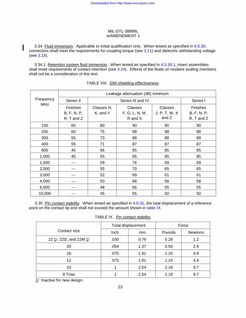
3.34 Fluid immersion. Applicable to initial qualification only. When tested as specified in 4.5.30,
connectors shall meet the requirements for coupling torque (see 3.11) and dielectric withstanding voltage (see 3.15).
3.34.1 Retention system fluid immersion. When tested as specified in 4.5.30.1, insert assemblies shall meet requirements of contact retention (see 3.24). Effects of the fluids on resilient sealing members shall not be a consideration of this test.
TABLE VIII. EMI shielding effectiveness.
Frequency
MHz
Leakage attenuation (dB) minimum
Series II Series III and IV Series I
Finishes B, F, N, P, R, T and Z
Classes H, K, and Y
Classes F, G, L, N, M,
R and S
Classes J, P, T, W, X
and Z
Finishes B, F, N, P, R, T and Z
100 65 80 90 90 90 200 60 75 88 88 88 300 55 73 88 88 88 400 55 71 87 87 87 800 45 66 85 85 85
1,000 45 65 85 85 85 1,500 --- 59 76 69 69 2,000 --- 55 70 65 65 3,000 --- 52 69 61 61 4,000 --- 50 68 58 58 6,000 --- 48 66 55 55 10,000 --- 45 65 50 50
3.35 Pin contact stability. When tested as specified in 4.5.31, the total displacement of a reference
point on the contact tip end shall not exceed the amount shown in table IX.
TABLE IX. Pin contact stability.
Contact size
Total displacement Force
Inch mm Pounds Newtons
22 1/, 22D, and 22M 1/ .030 0.76 0.28 1.2
20 .054 1.37 0.55 2.4
16 .075 1.91 1.10 4.9
12 .075 1.91 1.10 4.9
10 .1 2.54 2.18 9.7
8 Triax .1 2.54 2.18 9.7 1/ Inactive for new design.
Downloaded from http://www.everyspec.com
MIL-DTL-38999L w/AMENDMENT 1
24
3.36 Contact walkout. When tested as specified in 4.5.32, contacts shall not become dislodged from
their normal position.
3.37 Installing and removal tool abuse. Applicable to initial qualification only. When tested as specified in 4.5.33, there shall be no evidence of damage to the contacts, the connector insert, or the contact retaining mechanism.
3.38 High temperature exposure.
3.38.1 High temperature exposure with contact loading. When tested as specified in 4.5.34.1,
contacts shall maintain their specified locations as shown on figures 1, 2, 3, and 4 and there shall be no electrical discontinuity.
3.38.2 High temperature exposure. Applicable to series III except hermetics. When tested as specified in 4.5.34.2 for 1,000 hours, connectors shall perform satisfactorily and pass succeeding tests in the qualification test sequence.
3.39 Electrolytic erosion. Applicable to series III and IV only. When tested as specified in 4.5.35, pin contacts shall show no exposure of base metal due to electrolytic erosion. Corrosion deposits shall not be considered as defects.
3.40 Firewall. Applicable to classes K and S connectors only. Mated connectors shall prevent passing of a flame through the connector for at least 20 minutes when tested as specified in 4.5.36. During this period there shall be no flame from outgassing or other causes on the end of the connector protected by the firewall. The current specified in 4.5.36 shall be applied for the first 5 minutes without break in electrical continuity. During the next minute the connector shall draw no more than 2 amperes when a test potential of 100 to 125 V ac at 60 Hz is applied between adjacent contacts and between contacts and the shell.
3.41 Contact plating thickness. Applicable to hermetic connectors only. When tested as specified in 4.5.37, contacts used in hermetic connectors shall be gold plated to a minimum thickness of .000050 inch (0.00127 mm) with a suitable underplate as specified in 3.3.6.1. Hermetic connectors with heavy gold plating (contact styles G and U) shall be gold plated to a minimum thickness of .000100 inch (0.003 mm). Hermetic connectors with rhodium plating (contact styles R and M) shall be rhodium plated to a minimum thickness of .000050 inch (0.00127 mm). Nickel under plate for contact styles G, U, R and M shall be as specified in 3.3.6.1.
3.42 Contact engagement and separating force. Applicable to hermetic connectors with sockets only. When tested as specified in 4.5.38, contact engagement and separating forces shall be within the limits specified in SAE-AS39029.
3.43 Resistance to probe damage. Applicable to hermetic connectors with sockets only. When tested as specified in 4.5.39, contacts shall withstand the bending moment and depth of test probe insertion without evidence of damage that would interfere with the mechanical or electrical performance.
3.44 Ice resistance. Applicable to series I, III and IV only. When tested as specified in 4.5.40,
connectors shall pass succeeding tests in the qualification table. When tested in accordance with 4.5.7 uncoupling and recoupling torque shall not exceed the values specified in table IV by more than 25 percent.
Downloaded from http://www.everyspec.com
MIL-DTL-38999L w/AMENDMENT 1
25
3.45 Dust or fine sand. Applicable to series I, III and IV only. When tested as specified in 4.5.41,
connectors shall pass succeeding tests in the qualification table. When tested as specified in 4.5.7 , uncoupling and recoupling torque shall not exceed the values specified in table IV by more than 25 percent.
3.46 Thermal vacuum outgassing. Applicable to classes G and H for initial qualifications only. All nonmetallic materials used in the finished connector shall not release greater than 1.0 percent total mass loss (TML) and 0.1 percent collected volatile condensable material (CVCM) when tested as specified in 4.5.42.
3.47 Hydrolytic stability. Applicable to classes J and M only. For initial qualification only. When
tested as specified in 4.5.43, the connector shall be without defects detrimental to mechanical performance. There shall be no increase in the connector weight greater than 0.75 percent. When subjected to an overtorque at 150 percent of those values specified in table IV, there shall be no evidence of cracking, breaking, or loosening of parts.
3.48 Cavity-to-cavity leakage bonding integrity. When tested as specified in 4.5.44, there shall be no air leakage between contact cavities.
3.49 Impact. Applicable to classes J and M only. When connector plugs with SAE-AS85049 straight strain relief clamps are tested as specified in 4.5.45, there shall be no breaking or cracking of inserts or shells. Also, there shall be no bending of contacts nor any damage which would prevent the connector from mating or unmating.
3.50 Insert bond strength. When tested as specified in 4.5.46, there shall be no visible separation or cracks at the bond joint while an axial load is applied.
3.51 Resistance to indirect lightning strike. Series III only, all classes. When tested as specified in 4.5.47, wired and mated connectors shall meet braid shield braid-to-shell conductivity as specified in 4.5.25.1, coupling and uncoupling torque as specified in 4.5.7, insulation resistance at ambient temperature as specified in 4.5.10.1 and dielectric withstanding voltage at sea level as specified in 4.5.11.1. Connectors shall show no damage or degradation in the finish or base material that would affect subsequent use. Damage or hardening of elastomeric sealing members affecting sealing shall be considered a failure.
Downloaded from http://www.everyspec.com
MIL-DTL-38999L w/AMENDMENT 1
26
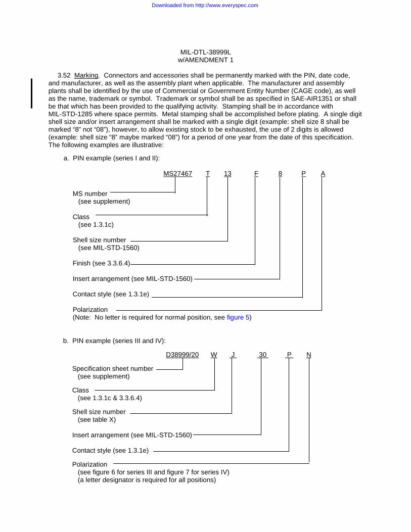
3.52 Marking. Connectors and accessories shall be permanently marked with the PIN, date code,
and manufacturer, as well as the assembly plant when applicable. The manufacturer and assembly plants shall be identified by the use of Commercial or Government Entity Number (CAGE code), as well as the name, trademark or symbol. Trademark or symbol shall be as specified in SAE-AIR1351 or shall be that which has been provided to the qualifying activity. Stamping shall be in accordance with MIL-STD-1285 where space permits. Metal stamping shall be accomplished before plating. A single digit shell size and/or insert arrangement shall be marked with a single digit (example: shell size 8 shall be marked “8” not “08”), however, to allow existing stock to be exhausted, the use of 2 digits is allowed (example: shell size “8” maybe marked “08”) for a period of one year from the date of this specification. The following examples are illustrative:
b. PIN example (series III and IV):
D38999/20 W J 30 P N
Specification sheet number (see supplement) Class (see 1.3.1c & 3.3.6.4) Shell size number (see table X) Insert arrangement (see MIL-STD-1560) Contact style (see 1.3.1e) Polarization (see figure 6 for series III and figure 7 for series IV) (a letter designator is required for all positions)
a. PIN example (series I and II):
MS27467 T 13 F 8 P A
MS number (see supplement) Class (see 1.3.1c) Shell size number (see MIL-STD-1560) Finish (see 3.3.6.4) Insert arrangement (see MIL-STD-1560) Contact style (see 1.3.1e) Polarization (Note: No letter is required for normal position, see figure 5)
Downloaded from http://www.everyspec.com
MIL-DTL-38999L w/AMENDMENT 1
27
c. Lot number - (example: 000010). d. JAN prefix - (see 3.52.2).
3.52.1 Contact location identification. Contact locations shall be identified as specified on the
applicable military standard. All positions shall be identified on the front and rear faces of the insert except where space limitations make this impracticable. Location of contact identifying characters shall be in close proximity to the holes but need not be placed exactly where specified on the standard. The preferred color of the contact identifying character is white. When the background is a color against which white is difficult to distinguish, a color will be chosen for which the identifying character can be easily distinguished.
3.52.2 JAN and J marking. The United States Government has adopted and is exercising legitimate control over the certification marks "JAN" and "J", respectively, to indicate that items so marked or identified are manufactured to, and meet all the requirements of specifications. Accordingly, items acquired to, and meeting all of the criteria specified herein and in applicable specifications, shall bear the certification mark "JAN" except that items too small to bear the certification mark "JAN" shall bear the letter "J". The "JAN" or "J" shall be placed immediately before the part number except that if such location would place a hardship on the manufacturer in connection with such marking, the "JAN" or "J" may be located on the first line above or below the part number. Items furnished under contracts or orders which either permit or require deviation from the conditions or requirements specified herein or in applicable specifications shall not bear "JAN" or "J". In the event an item fails to meet the requirements of this specification and the applicable specification sheets or associated detail specifications, the manufacturer shall remove completely the military part number and the "JAN" or the "J" from the sample tested and also from all items represented by the sample. The "JAN" or "J" certification mark shall not be used on products acquired to contractor drawings or specification. The United States Government has obtained Certificate of Registration Number 504,860 for the certification mark "JAN" and Registration Number 1,586,261 for the certification mark “J”.
Note: The “JAN” or “J” is not part of the PIN but indicates a certification.
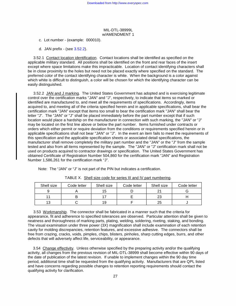
TABLE X. Shell size code for series III and IV part numbering.
Shell size Code letter Shell size Code letter Shell size Code letter 9 A 15 D 21 G
11 B 17 E 23 H 13 C 19 F 25 J
3.53 Workmanship. The connector shall be fabricated in a manner such that the criteria for
appearance, fit and adherence to specified tolerances are observed. Particular attention shall be given to neatness and thoroughness of marking parts, plating, welding, soldering, riveting, staking, and bonding. The visual examination under three power (3X) magnification shall include examination of each retention cavity for molding discrepancies, retention features, and excessive adhesive. The connectors shall be free from crazing, cracks, voids, pimples, chips, blisters, pinholes, sharp cutting edges, burrs, and other defects that will adversely affect life, serviceability, or appearance.
3.54 Change effectivity. Unless otherwise specified by the preparing activity and/or the qualifying
activity, all changes from the previous revision of MIL-DTL-38999 shall become effective within 90 days of the date of publication of the latest revision. If unable to implement changes within the 90 day time period, additional time shall be requested from the qualifying activity. Manufacturers that are QPL listed and have concerns regarding possible changes to retention reporting requirements should contact the qualifying activity for clarification.
Downloaded from http://www.everyspec.com
MIL-DTL-38999L w/AMENDMENT 1
28
3.55 Disposition of stock. Unless otherwise specified by the qualifying activity and coordinated with
the preparing activity, qualified manufacturers and their selling agents or distributors may ship from stock; connectors and accessories which were manufactured in accordance with the previous revision of MIL-DTL-38999 for a period of 18 months from the date of the latest revision, provided that form, fit and function requirements are not affected.
4. VERIFICATION
4.1 Classification of inspection. The examination and testing of connectors shall be classified as follows:
a. Qualification inspection (see 4.3). b. Conformance inspection (see 4.4).
4.2 Inspection conditions. Unless otherwise specified herein, all inspections shall be performed in
accordance with the test conditions specified in the "GENERAL REQUIREMENTS" of EIA-364. 4.2.1 Test equipment and inspection facilities. Test and measuring equipment and inspection
facilities of sufficient accuracy, quality and quantity to permit performance of the required inspection shall be established and maintained by the contractor. The establishment and maintenance of a calibration system to control the accuracy of the measuring and test equipment (i.e., industry standard, military standard) shall be required.
4.2.1.1 QPL system. The manufacturer shall establish and maintain a system to meet the requirements of MIL-STD-790 and the requirements herein (see 3.2.1). Evidence of such compliance shall be verified by the qualifying activity as a prerequisite for qualification and retention of qualification.
4.2.2 Fungus resistance certification. Certification to method 508.6 of MIL-STD-810 is required (see 3.3.3).
4.3 Qualification inspection. Qualification inspection shall be performed at a laboratory acceptable to the Government (see 6.3) on sample units produced with equipment and procedures normally used in production. Qualification approval may be granted upon successful completion of the inspections and tests of 4.3.3 conducted on samples of 4.3.1; such approval to include classes, finishes, shell configurations, and insert arrangements other than those actually tested, providing that the capability to manufacture these parts is demonstrated by providing exhibit samples or equivalent listing. Qualification of class K connectors also qualifies class S connectors providing class S connectors satisfactorily pass salt spray and group 4 tests. Qualification of class T, W, F, or K will qualify connectors for class Y for group 5 and group 11. Qualification of class T connectors also qualifies classes P and E connectors. Qualification of a new plating material or other specified characteristic on a connector also qualifies the same characteristic by similarity of a product with lower performance requirements, such as protective caps and covers or dummy stowage receptacles. However, qualification of a specified characteristic on a cap, cover or dummy stowage receptacle shall not qualify a connector with the same characteristic. For vibration testing (4.5.23), qualification of a higher performance connector, rated at 200°C, will qualify a lower performance connector produced with the same material and rated at 175°C.
Downloaded from http://www.everyspec.com
MIL-DTL-38999L w/AMENDMENT 1
29
4.3.1 Sample size. The following test samples, for each series manufactured by normal production
methods, shall be provided. Tested and untested connectors, accessories and materials may be required at no cost to the Government for qualification verification by the responsible qualification activity (see 6.3).
a. Two mating pairs of series I, II, III, and IV straight plugs and wall mounting receptacle of each of the nine shell sizes. Three shell sizes shall be service M, three shall be service I, and three shall be service II. Each arrangement in a given shell size shall be the most dense contact arrangement for that particular service rating. Half the samples of each shell size shall have pin contacts in the receptacle and socket contacts in the plug. The other samples shall have socket contacts in the receptacle and pin contacts in the plug. Straight strain relief clamps, when needed in order to perform testing on qualification samples, shall be in accordance with SAE-AS85049.
b. Two mating pairs, hermetic jam nut receptacle and straight plug, of each of the nine shell sizes.
Three shell sizes shall be service M, three shall be service I, and three shall be service II. Each arrangement in a given shell size shall be the most dense contact arrangement for that particular service rating. One sample of each shell size shall have pin contacts in the receptacle and socket contacts in the plug. The other sample shall have socket contacts in the receptacle and pin contacts in the plug. Contractors seeking qualification of one style only in hermetics shall provide both jam nut receptacles in that style with mating counterparts.
c. One straight plug with spring fingers and counterpart wall mounting receptacle of small,
medium, and large shell sizes with applicable EMI backshells.
d. One wall mounting receptacle with applicable conductive finish in small, medium, and large shell sizes, less coupling pins and inserts. These connectors must intermate with samples provided under 4.3.1c.
e. Ten mated pairs, straight plugs and wall mounting receptacles, of a medium shell size, in any
representative insert and shell size arrangement.
f. Ten straight plugs and wall mounting receptacles of various representative shell sizes and insert arrangements.
g. Sufficient, mating connectors, plugs, and wall mounting receptacles, in representative shell
sizes, to provide a minimum of 21 contact cavities of each applicable contact size.
h. Sufficient hermetic receptacles to provide the following quantities of pin contacts:
Size Quantity
22D 65 20, 16 50 12 35
i. For each shell size, one mating pair of series II and one mating pair of series I, III, and IV, will
be supplied with environmental backshells in accordance with SAE-AS85049 category 2B. Connectors shall be supplied in maximum density contact arrangements with pin contacts installed in the receptacles.
Downloaded from http://www.everyspec.com
MIL-DTL-38999L w/AMENDMENT 1
30
j. One mating pair of classes K and S receptacle and classes K and S straight plug of each of the
nine shell sizes. Three shell sizes shall be service M, three shall be service I, and three shall be service II. Each arrangement in a given shell size shall be the most dense contact arrangement for that particular service rating. All samples shall be provided with applicable SAE-AS85049 straight strain relief clamps.
k. One mating pair of series I, III, and IV straight plug and receptacle of each of the nine shell
sizes. Each arrangement in a given shell size shall be the most dense contact arrangement for that particular service rating.
l. Two bonded insert grommet assemblies and two bonded insert interface seal assemblies which
have not been assembled into the connector shell shall be tested. The assemblies shall be of the size and contact arrangement for which qualification is to be conducted (Sample size required for thermal vacuum outgassing test shall be as specified in ASTM E595).
m. One mating pair of unplated class J or M connectors (less inserts) in each shell size range
(small, medium and large). n. Three mating pairs of series III straight plugs and receptacles in shell sizes 9, 15, and 21 (nine
mating pairs total) in each class for which qualification is desired shall be tested. Each mating pair of connectors shall be provided with an SAE-AS85049 braidsock strain relief as specified in EIA/ECA-364-75. (Note: An SAE-AS85049/103 strain relief is recommended).
4.3.1.1 Sample size (limited qualification). Manufacturers that do not intend to qualify all nine shell
sizes in all series or all contact sizes shall provide the following test samples instead of those specified in 4.3.1a and 4.3.1b: Four mating pairs of each shell for each series or contact size to be qualified. The maximum number of connectors that will be tested is thirty-six. Future qualification of additional shell or contact sizes will require qualification as determined by the qualifying activity.
4.3.2 Preparation of samples. Except as otherwise specified for shielded contacts, wiring of
crimp-type contacts shall be accomplished using tools conforming to MIL-DTL-22520, class I. The length of stripped portion of conductor shall be at least long enough to reach the bottom of the crimp barrel, but shall not be so long that more than .031 inch (0.79 mm) of conductor is exposed at end of barrel when conductor end touches bottom of barrel. An alternate sample preparation may be used with the approval of the qualifying activity.
a. Samples provided under 4.3.1a shall be wired with wire having a smooth extruded outer jacket
of waterproof construction. One sample of each shell size for series II, and two samples of each shell size for series I, III, and IV, shall utilize maximum diameter wire and the remaining samples shall utilize minimum diameter wire. See table XI for example of wires that can be used to accomplish the required minimum and maximum diameter. Two cavities of each sample provided shall contain unwired contacts and sealing plugs in accordance with MS27488, SAE-AS85049/80 or SAE-AS85049/81, as applicable. Connectors with less than four contacts of a given contact size will not have sealing plugs installed for that contact size. Box mount connectors may be potted at any convenient stage in the test prior to altitude immersion in group 1 and humidity in group 2.
Downloaded from http://www.everyspec.com
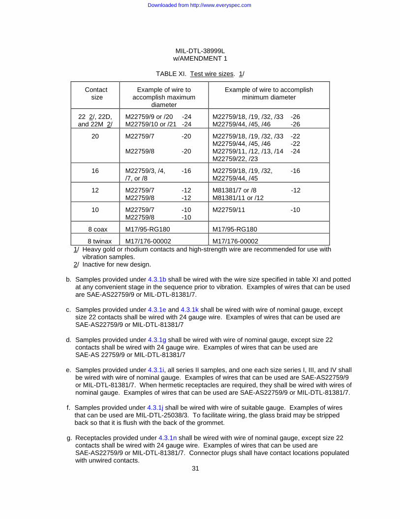
MIL-DTL-38999L w/AMENDMENT 1
31
TABLE XI. Test wire sizes. 1/
Contact
size
Example of wire to
accomplish maximum diameter
Example of wire to accomplish
minimum diameter
22 2/, 22D, and 22M 2/
M22759/9 or /20 -24 M22759/10 or /21 -24
M22759/18, /19, /32, /33 -26 M22759/44, /45, /46 -26
20
M22759/7 -20 M22759/8 -20
M22759/18, /19, /32, /33 -22 M22759/44, /45, /46 -22 M22759/11, /12, /13, /14 -24 M22759/22, /23
16
M22759/3, /4, -16 /7, or /8
M22759/18, /19, /32, -16 M22759/44, /45
12
M22759/7 -12 M22759/8 -12
M81381/7 or /8 -12 M81381/11 or /12
10
M22759/7 -10 M22759/8 -10
M22759/11 -10
8 coax
M17/95-RG180
M17/95-RG180
8 twinax
M17/176-00002
M17/176-00002
1/ Heavy gold or rhodium contacts and high-strength wire are recommended for use with vibration samples. 2/ Inactive for new design.
b. Samples provided under 4.3.1b shall be wired with the wire size specified in table XI and potted
at any convenient stage in the sequence prior to vibration. Examples of wires that can be used are SAE-AS22759/9 or MIL-DTL-81381/7.
c. Samples provided under 4.3.1e and 4.3.1k shall be wired with wire of nominal gauge, except
size 22 contacts shall be wired with 24 gauge wire. Examples of wires that can be used are SAE-AS22759/9 or MIL-DTL-81381/7
d. Samples provided under 4.3.1g shall be wired with wire of nominal gauge, except size 22
contacts shall be wired with 24 gauge wire. Examples of wires that can be used are SAE-AS 22759/9 or MIL-DTL-81381/7
e. Samples provided under 4.3.1i, all series II samples, and one each size series I, III, and IV shall
be wired with wire of nominal gauge. Examples of wires that can be used are SAE-AS22759/9 or MIL-DTL-81381/7. When hermetic receptacles are required, they shall be wired with wires of nominal gauge. Examples of wires that can be used are SAE-AS22759/9 or MIL-DTL-81381/7.
f. Samples provided under 4.3.1j shall be wired with wire of suitable gauge. Examples of wires
that can be used are MIL-DTL-25038/3. To facilitate wiring, the glass braid may be stripped back so that it is flush with the back of the grommet.
g. Receptacles provided under 4.3.1n shall be wired with wire of nominal gauge, except size 22
contacts shall be wired with 24 gauge wire. Examples of wires that can be used are SAE-AS22759/9 or MIL-DTL-81381/7. Connector plugs shall have contact locations populated with unwired contacts.
Downloaded from http://www.everyspec.com
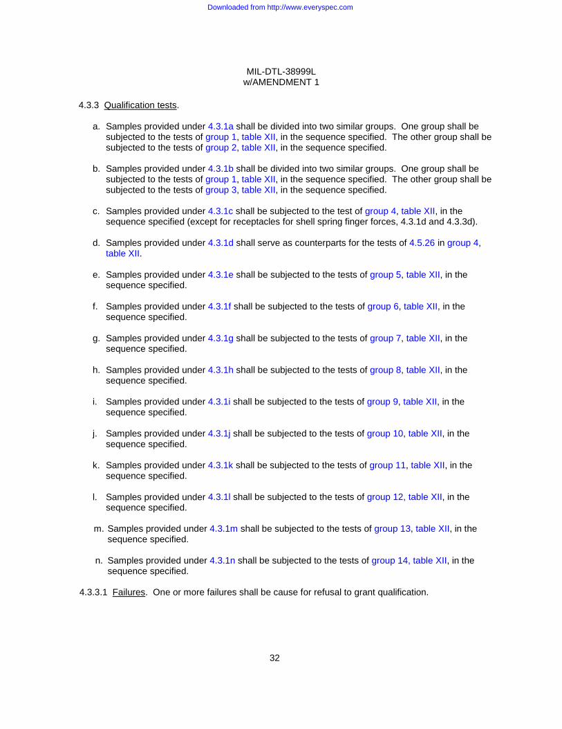
MIL-DTL-38999L w/AMENDMENT 1
32
4.3.3 Qualification tests.
a. Samples provided under 4.3.1a shall be divided into two similar groups. One group shall be
subjected to the tests of group 1, table XII, in the sequence specified. The other group shall be subjected to the tests of group 2, table XII, in the sequence specified.
b. Samples provided under 4.3.1b shall be divided into two similar groups. One group shall be
subjected to the tests of group 1, table XII, in the sequence specified. The other group shall be subjected to the tests of group 3, table XII, in the sequence specified.
c. Samples provided under 4.3.1c shall be subjected to the test of group 4, table XII, in the
sequence specified (except for receptacles for shell spring finger forces, 4.3.1d and 4.3.3d).
d. Samples provided under 4.3.1d shall serve as counterparts for the tests of 4.5.26 in group 4, table XII.
e. Samples provided under 4.3.1e shall be subjected to the tests of group 5, table XII, in the
sequence specified.
f. Samples provided under 4.3.1f shall be subjected to the tests of group 6, table XII, in the sequence specified.
g. Samples provided under 4.3.1g shall be subjected to the tests of group 7, table XII, in the
sequence specified.
h. Samples provided under 4.3.1h shall be subjected to the tests of group 8, table XII, in the sequence specified.
i. Samples provided under 4.3.1i shall be subjected to the tests of group 9, table XII, in the
sequence specified.
j. Samples provided under 4.3.1j shall be subjected to the tests of group 10, table XII, in the sequence specified.
k. Samples provided under 4.3.1k shall be subjected to the tests of group 11, table XII, in the
sequence specified.
l. Samples provided under 4.3.1l shall be subjected to the tests of group 12, table XII, in the sequence specified.
m. Samples provided under 4.3.1m shall be subjected to the tests of group 13, table XII, in the
sequence specified.
n. Samples provided under 4.3.1n shall be subjected to the tests of group 14, table XII, in the sequence specified.
4.3.3.1 Failures. One or more failures shall be cause for refusal to grant qualification.
Downloaded from http://www.everyspec.com
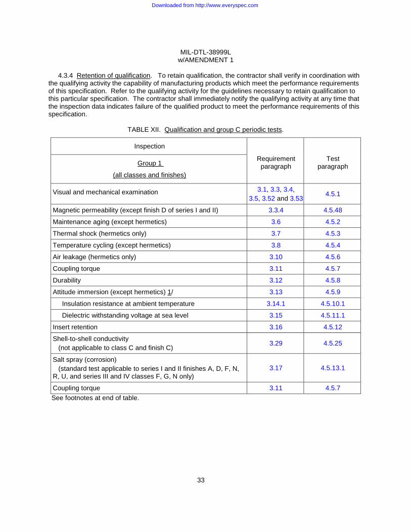
MIL-DTL-38999L w/AMENDMENT 1
33
4.3.4 Retention of qualification. To retain qualification, the contractor shall verify in coordination with
the qualifying activity the capability of manufacturing products which meet the performance requirements of this specification. Refer to the qualifying activity for the guidelines necessary to retain qualification to this particular specification. The contractor shall immediately notify the qualifying activity at any time that the inspection data indicates failure of the qualified product to meet the performance requirements of this specification.
TABLE XII. Qualification and group C periodic tests.
Inspection
Requirement paragraph
Test paragraph Group 1
(all classes and finishes)
Visual and mechanical examination 3.1, 3.3, 3.4, 3.5, 3.52 and 3.53
4.5.1
Magnetic permeability (except finish D of series I and II) 3.3.4 4.5.48
Maintenance aging (except hermetics) 3.6 4.5.2
Thermal shock (hermetics only) 3.7 4.5.3
Temperature cycling (except hermetics) 3.8 4.5.4
Air leakage (hermetics only) 3.10 4.5.6
Coupling torque 3.11 4.5.7
Durability 3.12 4.5.8
Attitude immersion (except hermetics) 1/ 3.13 4.5.9
Insulation resistance at ambient temperature 3.14.1 4.5.10.1
Dielectric withstanding voltage at sea level 3.15 4.5.11.1
Insert retention 3.16 4.5.12
Shell-to-shell conductivity (not applicable to class C and finish C)
3.29 4.5.25
Salt spray (corrosion) (standard test applicable to series I and II finishes A, D, F, N, R, U, and series III and IV classes F, G, N only)
3.17 4.5.13.1
Coupling torque 3.11 4.5.7 See footnotes at end of table.
Downloaded from http://www.everyspec.com
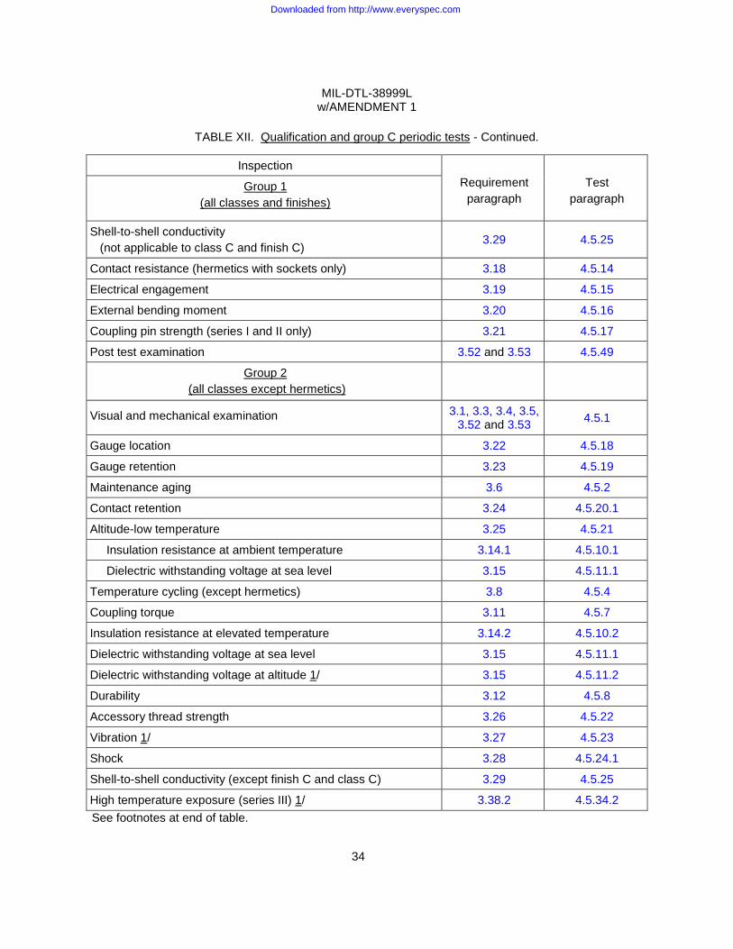
MIL-DTL-38999L w/AMENDMENT 1
34
TABLE XII. Qualification and group C periodic tests - Continued.
Inspection Requirement
paragraph Test
paragraph Group 1
(all classes and finishes)
Shell-to-shell conductivity (not applicable to class C and finish C)
3.29 4.5.25
Contact resistance (hermetics with sockets only) 3.18 4.5.14
Electrical engagement 3.19 4.5.15
External bending moment 3.20 4.5.16
Coupling pin strength (series I and II only) 3.21 4.5.17
Post test examination 3.52 and 3.53 4.5.49
Group 2 (all classes except hermetics)
Visual and mechanical examination 3.1, 3.3, 3.4, 3.5, 3.52 and 3.53 4.5.1
Gauge location 3.22 4.5.18
Gauge retention 3.23 4.5.19
Maintenance aging 3.6 4.5.2
Contact retention 3.24 4.5.20.1
Altitude-low temperature 3.25 4.5.21
Insulation resistance at ambient temperature 3.14.1 4.5.10.1
Dielectric withstanding voltage at sea level 3.15 4.5.11.1
Temperature cycling (except hermetics) 3.8 4.5.4
Coupling torque 3.11 4.5.7
Insulation resistance at elevated temperature 3.14.2 4.5.10.2
Dielectric withstanding voltage at sea level 3.15 4.5.11.1
Dielectric withstanding voltage at altitude 1/ 3.15 4.5.11.2
Durability 3.12 4.5.8
Accessory thread strength 3.26 4.5.22
Vibration 1/ 3.27 4.5.23
Shock 3.28 4.5.24.1
Shell-to-shell conductivity (except finish C and class C) 3.29 4.5.25
High temperature exposure (series III) 1/ 3.38.2 4.5.34.2 See footnotes at end of table.
Downloaded from http://www.everyspec.com
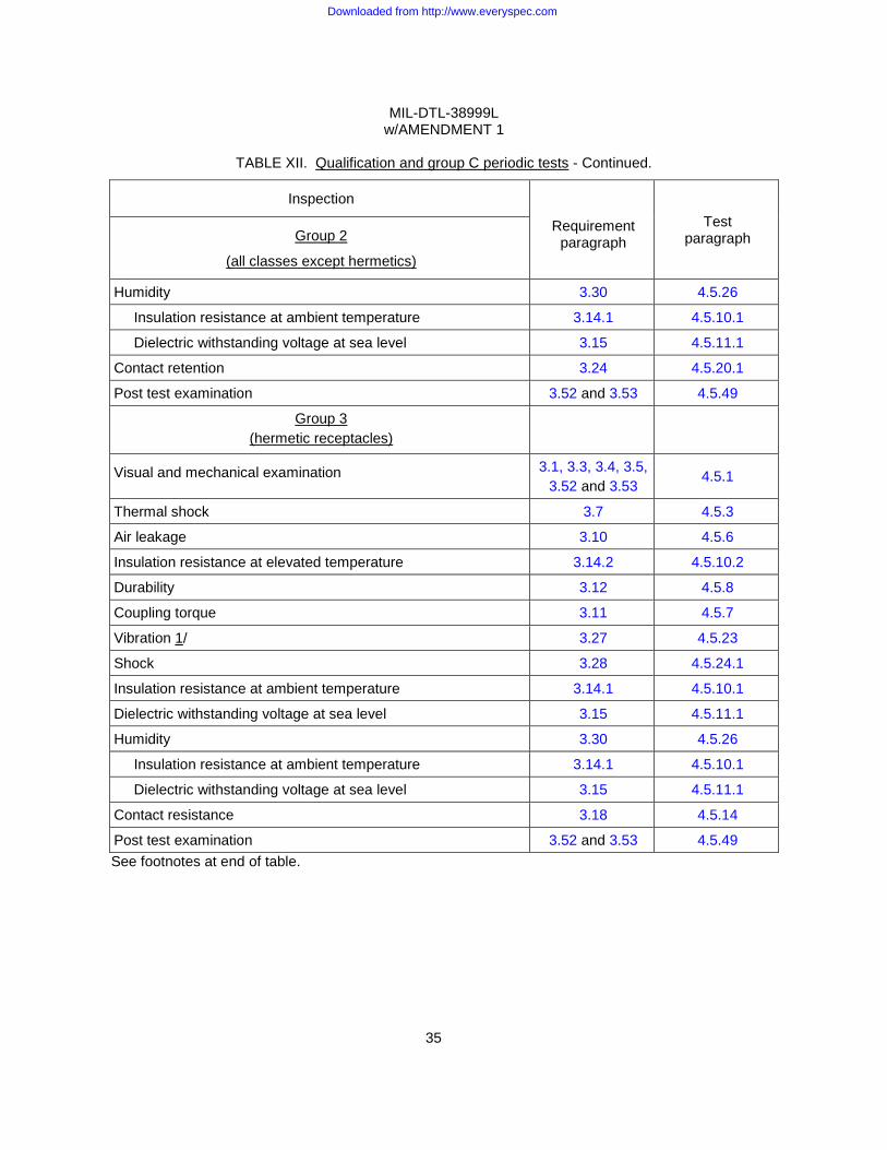
MIL-DTL-38999L w/AMENDMENT 1
35
TABLE XII. Qualification and group C periodic tests - Continued.
Inspection
Requirement paragraph
Test paragraph Group 2
(all classes except hermetics)
Humidity 3.30 4.5.26
Insulation resistance at ambient temperature 3.14.1 4.5.10.1
Dielectric withstanding voltage at sea level 3.15 4.5.11.1
Contact retention 3.24 4.5.20.1
Post test examination 3.52 and 3.53 4.5.49
Group 3 (hermetic receptacles)
Visual and mechanical examination 3.1, 3.3, 3.4, 3.5, 3.52 and 3.53
4.5.1
Thermal shock 3.7 4.5.3
Air leakage 3.10 4.5.6
Insulation resistance at elevated temperature 3.14.2 4.5.10.2
Durability 3.12 4.5.8
Coupling torque 3.11 4.5.7
Vibration 1/ 3.27 4.5.23
Shock 3.28 4.5.24.1
Insulation resistance at ambient temperature 3.14.1 4.5.10.1
Dielectric withstanding voltage at sea level 3.15 4.5.11.1
Humidity 3.30 4.5.26
Insulation resistance at ambient temperature 3.14.1 4.5.10.1
Dielectric withstanding voltage at sea level 3.15 4.5.11.1
Contact resistance 3.18 4.5.14
Post test examination 3.52 and 3.53 4.5.49 See footnotes at end of table.
Downloaded from http://www.everyspec.com
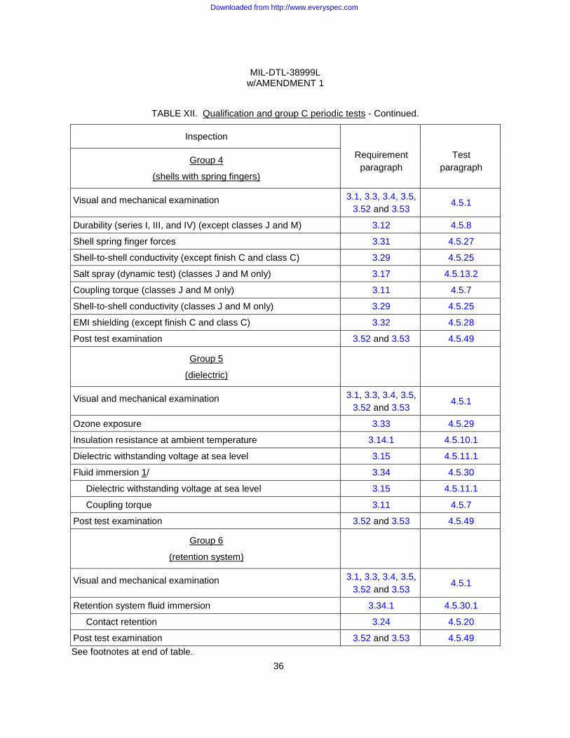
MIL-DTL-38999L w/AMENDMENT 1
36
TABLE XII. Qualification and group C periodic tests - Continued.
Inspection
Requirement paragraph
Test paragraph
Group 4
(shells with spring fingers)
Visual and mechanical examination 3.1, 3.3, 3.4, 3.5, 3.52 and 3.53
4.5.1
Durability (series I, III, and IV) (except classes J and M) 3.12 4.5.8
Shell spring finger forces 3.31 4.5.27
Shell-to-shell conductivity (except finish C and class C) 3.29 4.5.25
Salt spray (dynamic test) (classes J and M only) 3.17 4.5.13.2
Coupling torque (classes J and M only) 3.11 4.5.7
Shell-to-shell conductivity (classes J and M only) 3.29 4.5.25
EMI shielding (except finish C and class C) 3.32 4.5.28
Post test examination 3.52 and 3.53 4.5.49
Group 5
(dielectric)
Visual and mechanical examination 3.1, 3.3, 3.4, 3.5, 3.52 and 3.53
4.5.1
Ozone exposure 3.33 4.5.29
Insulation resistance at ambient temperature 3.14.1 4.5.10.1
Dielectric withstanding voltage at sea level 3.15 4.5.11.1
Fluid immersion 1/ 3.34 4.5.30
Dielectric withstanding voltage at sea level 3.15 4.5.11.1
Coupling torque 3.11 4.5.7
Post test examination 3.52 and 3.53 4.5.49
Group 6
(retention system)
Visual and mechanical examination 3.1, 3.3, 3.4, 3.5, 3.52 and 3.53
4.5.1
Retention system fluid immersion 3.34.1 4.5.30.1
Contact retention 3.24 4.5.20
Post test examination 3.52 and 3.53 4.5.49 See footnotes at end of table.
Downloaded from http://www.everyspec.com
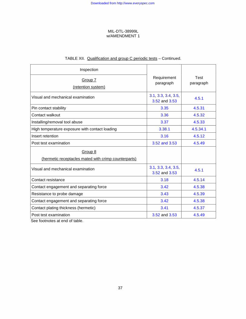
MIL-DTL-38999L w/AMENDMENT 1
37
TABLE XII. Qualification and group C periodic tests – Continued.
Inspection
Requirement paragraph
Test paragraph
Group 7
(retention system)
Visual and mechanical examination 3.1, 3.3, 3.4, 3.5, 3.52 and 3.53
4.5.1
Pin contact stability 3.35 4.5.31
Contact walkout 3.36 4.5.32
Installing/removal tool abuse 3.37 4.5.33
High temperature exposure with contact loading 3.38.1 4.5.34.1
Insert retention 3.16 4.5.12
Post test examination 3.52 and 3.53 4.5.49
Group 8
(hermetic receptacles mated with crimp counterparts)
Visual and mechanical examination 3.1, 3.3, 3.4, 3.5, 3.52 and 3.53
4.5.1
Contact resistance 3.18 4.5.14
Contact engagement and separating force 3.42 4.5.38
Resistance to probe damage 3.43 4.5.39
Contact engagement and separating force 3.42 4.5.38
Contact plating thickness (hermetic) 3.41 4.5.37
Post test examination 3.52 and 3.53 4.5.49 See footnotes at end of table.
Downloaded from http://www.everyspec.com

MIL-DTL-38999L w/AMENDMENT 1
38
TABLE XII. Qualification and group C periodic tests - Continued.
Inspection
Requirement paragraph
Test paragraph
Group 9
(series I, finish N series I and II – finishes B, C, E, P, T, X and Z)
(series III and IV – classes C, F, G, H, J, K, L, N, M, P, R, S, T, U, W, X, Y and Z)
Visual and mechanical examination 3.1, 3.3, 3.4, 3.5, 3.52 and 3.53
4.5.1
Shock (high impact) (series I, III, and IV only) 3.28 4.5.24.2
Dielectric withstanding voltage (at sea level) 3.15 4.5.11.1
Electrolytic erosion (series III and IV) 3.39 4.5.35
Shell-to-shell conductivity (not applicable to class C and finish C)
3.29 4.5.25
Temperature cycling (except hermetics) 3.8 4.5.4
Salt spray (corrosion) (dynamic test applicable to series I and II finishes B,C,E,P,T,X Z and series III and IV classes C,H,J,K,L,M,P,S,T,W,X,Y and Z)
3.17 4.5.13.2
Coupling torque 3.11 4.5.7
Shell-to-shell conductivity (not applicable to class C and finish C)
3.29 4.5.25
Coupling pin strength (series I and II only) 3.21 4.5.17
Post test examination 3.52 and 3.53 4.5.49
Group 10 3/
(firewall-classes K and S)
Visual and mechanical examination 3.1, 3.3, 3.4, 3.5, 3.52 and 3.53
4.5.1
Firewall (classes K and S connectors) 3.40 4.5.36
Post test examination 3.52 and 3.53 4.5.49 See footnotes at end of table.
Downloaded from http://www.everyspec.com
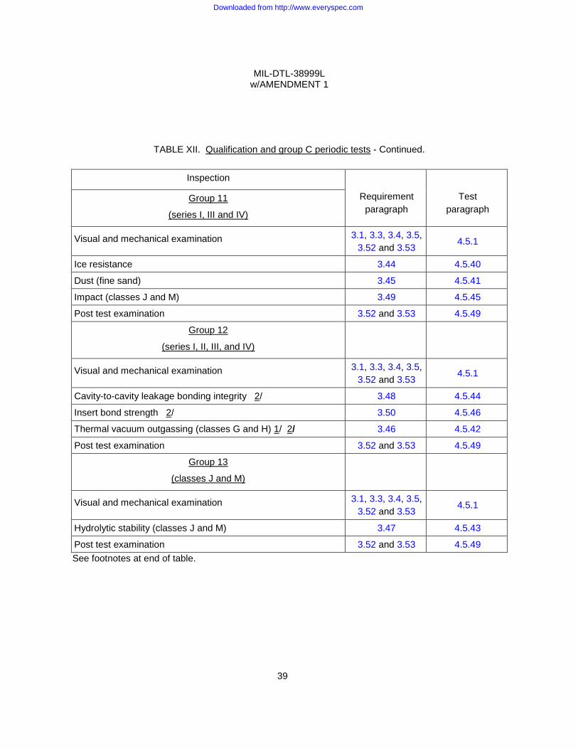
MIL-DTL-38999L w/AMENDMENT 1
39
TABLE XII. Qualification and group C periodic tests - Continued.
Inspection
Requirement paragraph
Test paragraph
Group 11
(series I, III and IV)
Visual and mechanical examination 3.1, 3.3, 3.4, 3.5, 3.52 and 3.53
4.5.1
Ice resistance 3.44 4.5.40
Dust (fine sand) 3.45 4.5.41
Impact (classes J and M) 3.49 4.5.45
Post test examination 3.52 and 3.53 4.5.49
Group 12
(series I, II, III, and IV)
Visual and mechanical examination 3.1, 3.3, 3.4, 3.5, 3.52 and 3.53
4.5.1
Cavity-to-cavity leakage bonding integrity 2/ 3.48 4.5.44
Insert bond strength 2/ 3.50 4.5.46
Thermal vacuum outgassing (classes G and H) 1/ 2/ 3.46 4.5.42
Post test examination 3.52 and 3.53 4.5.49
Group 13
(classes J and M)
Visual and mechanical examination 3.1, 3.3, 3.4, 3.5, 3.52 and 3.53
4.5.1
Hydrolytic stability (classes J and M) 3.47 4.5.43
Post test examination 3.52 and 3.53 4.5.49 See footnotes at end of table.
Downloaded from http://www.everyspec.com
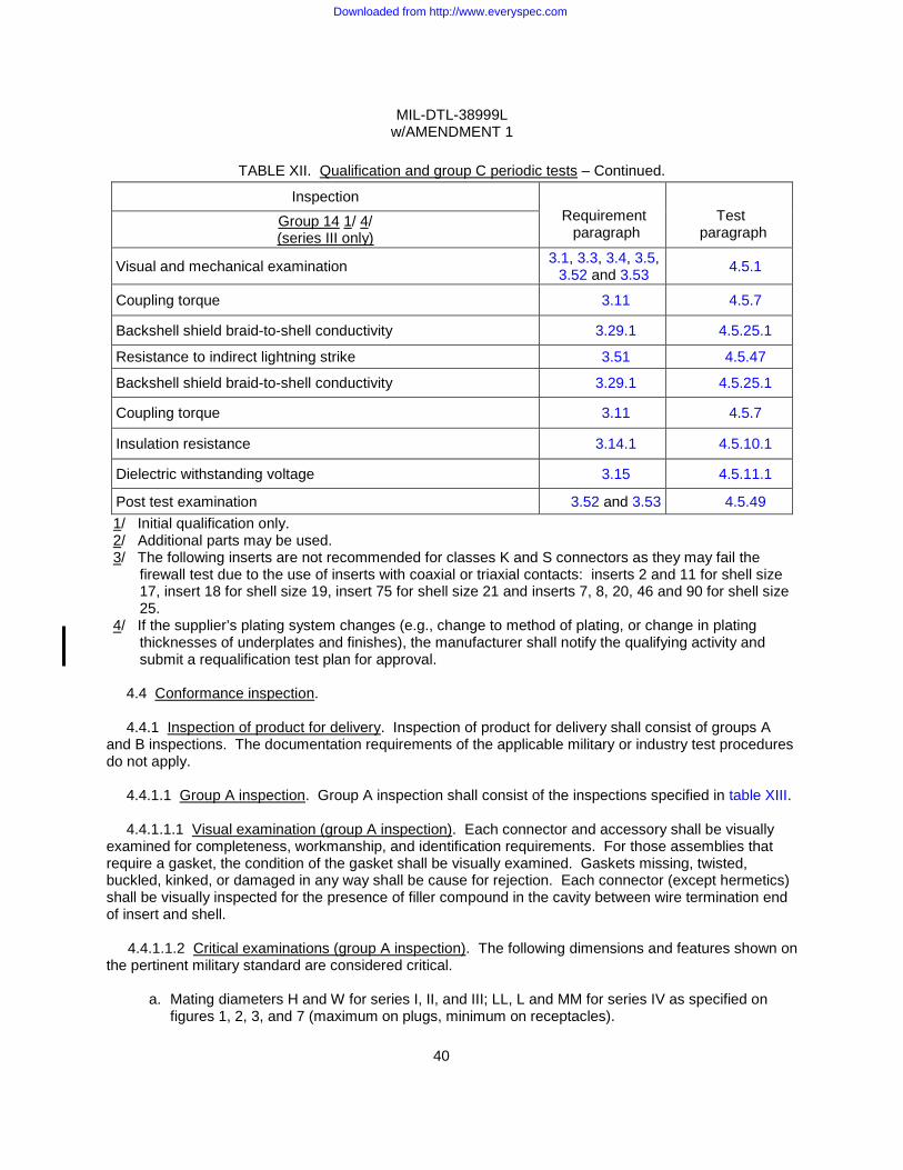
MIL-DTL-38999L w/AMENDMENT 1
40
TABLE XII. Qualification and group C periodic tests – Continued.
Inspection Requirement
paragraph Test
paragraph Group 14 1/ 4/ (series III only)
Visual and mechanical examination 3.1, 3.3, 3.4, 3.5, 3.52 and 3.53 4.5.1
Coupling torque 3.11 4.5.7
Backshell shield braid-to-shell conductivity 3.29.1 4.5.25.1
Resistance to indirect lightning strike 3.51 4.5.47
Backshell shield braid-to-shell conductivity 3.29.1 4.5.25.1
Coupling torque 3.11 4.5.7
Insulation resistance 3.14.1 4.5.10.1
Dielectric withstanding voltage 3.15 4.5.11.1
Post test examination 3.52 and 3.53 4.5.49 1/ Initial qualification only. 2/ Additional parts may be used. 3/ The following inserts are not recommended for classes K and S connectors as they may fail the
firewall test due to the use of inserts with coaxial or triaxial contacts: inserts 2 and 11 for shell size 17, insert 18 for shell size 19, insert 75 for shell size 21 and inserts 7, 8, 20, 46 and 90 for shell size 25.
4/ If the supplier’s plating system changes (e.g., change to method of plating, or change in plating thicknesses of underplates and finishes), the manufacturer shall notify the qualifying activity and submit a requalification test plan for approval.
4.4 Conformance inspection.
4.4.1 Inspection of product for delivery. Inspection of product for delivery shall consist of groups A
and B inspections. The documentation requirements of the applicable military or industry test procedures do not apply.
4.4.1.1 Group A inspection. Group A inspection shall consist of the inspections specified in table XIII.
4.4.1.1.1 Visual examination (group A inspection). Each connector and accessory shall be visually examined for completeness, workmanship, and identification requirements. For those assemblies that require a gasket, the condition of the gasket shall be visually examined. Gaskets missing, twisted, buckled, kinked, or damaged in any way shall be cause for rejection. Each connector (except hermetics) shall be visually inspected for the presence of filler compound in the cavity between wire termination end of insert and shell.
4.4.1.1.2 Critical examinations (group A inspection). The following dimensions and features shown on the pertinent military standard are considered critical.
a. Mating diameters H and W for series I, II, and III; LL, L and MM for series IV as specified on figures 1, 2, 3, and 7 (maximum on plugs, minimum on receptacles).
Downloaded from http://www.everyspec.com
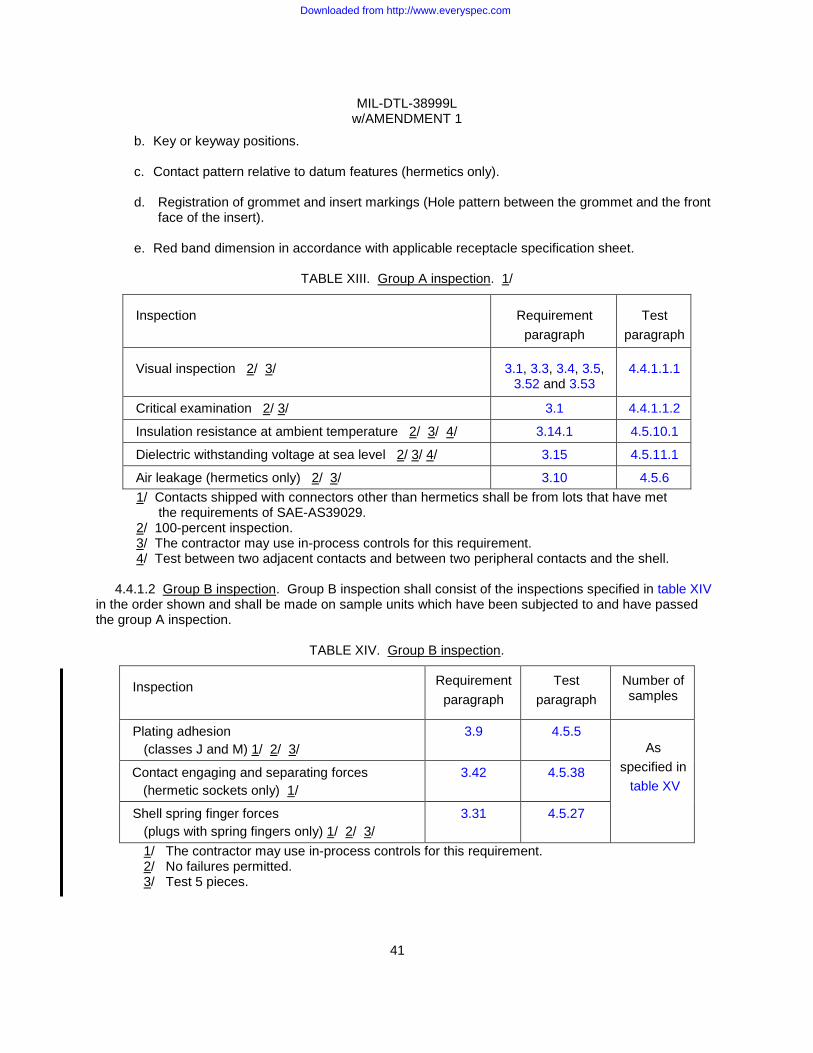
MIL-DTL-38999L w/AMENDMENT 1
41
b. Key or keyway positions.
c. Contact pattern relative to datum features (hermetics only).
d. Registration of grommet and insert markings (Hole pattern between the grommet and the front face of the insert).
e. Red band dimension in accordance with applicable receptacle specification sheet.
TABLE XIII. Group A inspection. 1/
Inspection
Requirement
paragraph
Test
paragraph Visual inspection 2/ 3/
3.1, 3.3, 3.4, 3.5,
3.52 and 3.53
4.4.1.1.1
Critical examination 2/ 3/ 3.1 4.4.1.1.2
Insulation resistance at ambient temperature 2/ 3/ 4/ 3.14.1 4.5.10.1
Dielectric withstanding voltage at sea level 2/ 3/ 4/ 3.15 4.5.11.1
Air leakage (hermetics only) 2/ 3/ 3.10 4.5.6 1/ Contacts shipped with connectors other than hermetics shall be from lots that have met the requirements of SAE-AS39029. 2/ 100-percent inspection. 3/ The contractor may use in-process controls for this requirement. 4/ Test between two adjacent contacts and between two peripheral contacts and the shell.
4.4.1.2 Group B inspection. Group B inspection shall consist of the inspections specified in table XIV in the order shown and shall be made on sample units which have been subjected to and have passed the group A inspection.
TABLE XIV. Group B inspection.
Inspection Requirement
paragraph Test
paragraph Number of samples
Plating adhesion (classes J and M) 1/ 2/ 3/
3.9 4.5.5 As
specified in table XV
Contact engaging and separating forces (hermetic sockets only) 1/
3.42 4.5.38
Shell spring finger forces (plugs with spring fingers only) 1/ 2/ 3/
3.31 4.5.27
1/ The contractor may use in-process controls for this requirement. 2/ No failures permitted. 3/ Test 5 pieces.
Downloaded from http://www.everyspec.com
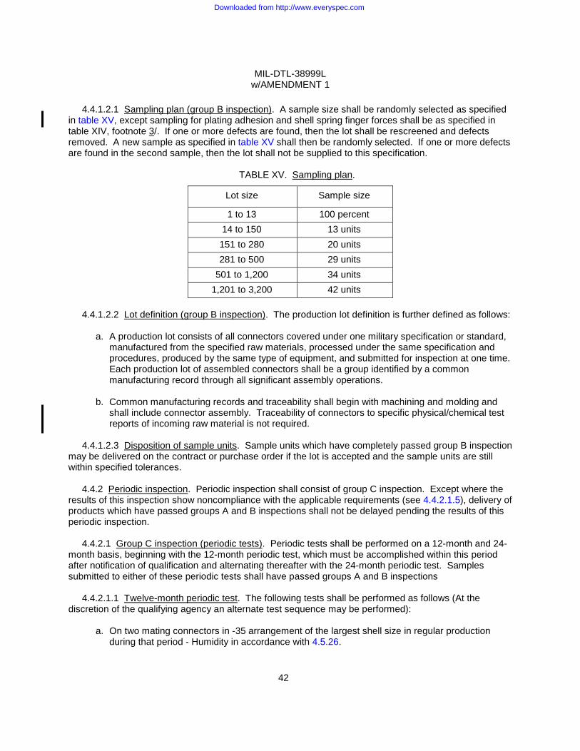
MIL-DTL-38999L w/AMENDMENT 1
42
4.4.1.2.1 Sampling plan (group B inspection). A sample size shall be randomly selected as specified
in table XV, except sampling for plating adhesion and shell spring finger forces shall be as specified in table XIV, footnote 3/. If one or more defects are found, then the lot shall be rescreened and defects removed. A new sample as specified in table XV shall then be randomly selected. If one or more defects are found in the second sample, then the lot shall not be supplied to this specification.
TABLE XV. Sampling plan.
Lot size Sample size
1 to 13 100 percent 14 to 150 13 units 151 to 280 20 units 281 to 500 29 units
501 to 1,200 34 units 1,201 to 3,200 42 units
4.4.1.2.2 Lot definition (group B inspection). The production lot definition is further defined as follows:
a. A production lot consists of all connectors covered under one military specification or standard,
manufactured from the specified raw materials, processed under the same specification and procedures, produced by the same type of equipment, and submitted for inspection at one time. Each production lot of assembled connectors shall be a group identified by a common manufacturing record through all significant assembly operations.
b. Common manufacturing records and traceability shall begin with machining and molding and
shall include connector assembly. Traceability of connectors to specific physical/chemical test reports of incoming raw material is not required.
4.4.1.2.3 Disposition of sample units. Sample units which have completely passed group B inspection
may be delivered on the contract or purchase order if the lot is accepted and the sample units are still within specified tolerances.
4.4.2 Periodic inspection. Periodic inspection shall consist of group C inspection. Except where the results of this inspection show noncompliance with the applicable requirements (see 4.4.2.1.5), delivery of products which have passed groups A and B inspections shall not be delayed pending the results of this periodic inspection.
4.4.2.1 Group C inspection (periodic tests). Periodic tests shall be performed on a 12-month and 24-month basis, beginning with the 12-month periodic test, which must be accomplished within this period after notification of qualification and alternating thereafter with the 24-month periodic test. Samples submitted to either of these periodic tests shall have passed groups A and B inspections
4.4.2.1.1 Twelve-month periodic test. The following tests shall be performed as follows (At the discretion of the qualifying agency an alternate test sequence may be performed):
a. On two mating connectors in -35 arrangement of the largest shell size in regular production during that period - Humidity in accordance with 4.5.26.
Downloaded from http://www.everyspec.com
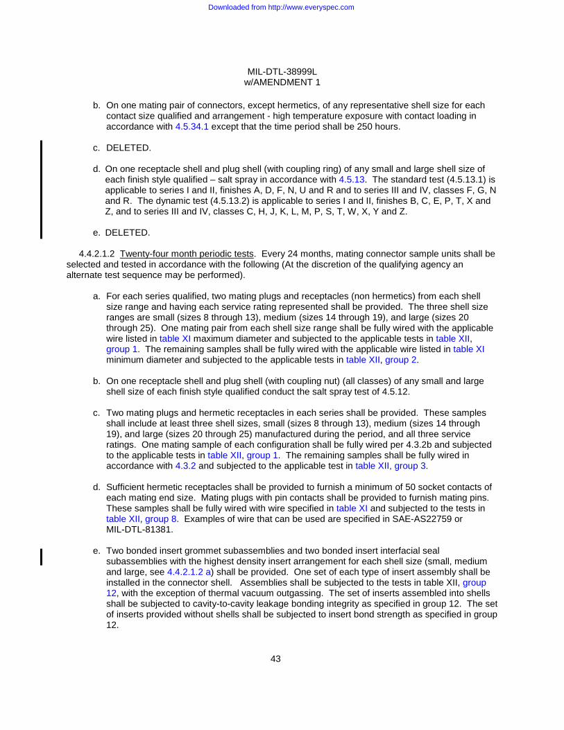
MIL-DTL-38999L w/AMENDMENT 1
43
b. On one mating pair of connectors, except hermetics, of any representative shell size for each
contact size qualified and arrangement - high temperature exposure with contact loading in accordance with 4.5.34.1 except that the time period shall be 250 hours.
c. DELETED. d. On one receptacle shell and plug shell (with coupling ring) of any small and large shell size of
each finish style qualified – salt spray in accordance with 4.5.13. The standard test (4.5.13.1) is applicable to series I and II, finishes A, D, F, N, U and R and to series III and IV, classes F, G, N and R. The dynamic test (4.5.13.2) is applicable to series I and II, finishes B, C, E, P, T, X and Z, and to series III and IV, classes C, H, J, K, L, M, P, S, T, W, X, Y and Z.
e. DELETED.
4.4.2.1.2 Twenty-four month periodic tests. Every 24 months, mating connector sample units shall be
selected and tested in accordance with the following (At the discretion of the qualifying agency an alternate test sequence may be performed).
a. For each series qualified, two mating plugs and receptacles (non hermetics) from each shell size range and having each service rating represented shall be provided. The three shell size ranges are small (sizes 8 through 13), medium (sizes 14 through 19), and large (sizes 20 through 25). One mating pair from each shell size range shall be fully wired with the applicable wire listed in table XI maximum diameter and subjected to the applicable tests in table XII, group 1. The remaining samples shall be fully wired with the applicable wire listed in table XI minimum diameter and subjected to the applicable tests in table XII, group 2.
b. On one receptacle shell and plug shell (with coupling nut) (all classes) of any small and large
shell size of each finish style qualified conduct the salt spray test of 4.5.12.
c. Two mating plugs and hermetic receptacles in each series shall be provided. These samples shall include at least three shell sizes, small (sizes 8 through 13), medium (sizes 14 through 19), and large (sizes 20 through 25) manufactured during the period, and all three service ratings. One mating sample of each configuration shall be fully wired per 4.3.2b and subjected to the applicable tests in table XII, group 1. The remaining samples shall be fully wired in accordance with 4.3.2 and subjected to the applicable test in table XII, group 3.
d. Sufficient hermetic receptacles shall be provided to furnish a minimum of 50 socket contacts of
each mating end size. Mating plugs with pin contacts shall be provided to furnish mating pins. These samples shall be fully wired with wire specified in table XI and subjected to the tests in table XII, group 8. Examples of wire that can be used are specified in SAE-AS22759 or MIL-DTL-81381.
e. Two bonded insert grommet subassemblies and two bonded insert interfacial seal
subassemblies with the highest density insert arrangement for each shell size (small, medium and large, see 4.4.2.1.2 a) shall be provided. One set of each type of insert assembly shall be installed in the connector shell. Assemblies shall be subjected to the tests in table XII, group 12, with the exception of thermal vacuum outgassing. The set of inserts assembled into shells shall be subjected to cavity-to-cavity leakage bonding integrity as specified in group 12. The set of inserts provided without shells shall be subjected to insert bond strength as specified in group 12.
Downloaded from http://www.everyspec.com
MIL-DTL-38999L w/AMENDMENT 1
44
4.4.2.1.3 Failures. If one or more sample units fail to pass group C inspection, the sample shall be
considered to have failed and corrective action shall be taken in accordance with 4.4.2.1.5. 4.4.2.1.4 Disposition of sample units. Sample units which have been subjected to group C inspection
shall not be delivered on the contract or purchase order.
4.4.2.1.5 Noncompliance. If a sample fails to pass group C inspection, the manufacturer shall take corrective action on the materials or processes or both, as warranted, and on all units of product which are to be corrected and which were manufactured with essentially the same materials and processes, and which are considered subject to the same failure. Acceptance and shipment of the product shall be discontinued until corrective action acceptable to the qualifying activity has been taken. After the corrective action has been taken, group C inspection shall be repeated on additional sample units (all inspections, or the inspection which the original sample failed, at the option of the qualifying activity). Groups A and B inspections may be reinstituted; however, final acceptance shall be withheld until the group C reinspection has shown that corrective action was successful. In the event of failure after reinspection, information concerning the failure shall be furnished to the cognizant inspection activity and the qualifying activity.
4.4.3 Failures of groups A, B or C. Lots which fail groups A, B or C and also either fail retesting or are not submitted for retesting, shall not be shipped, and the PIN and "JAN" marking shall be removed within 30 days from product produced to these lots (see 3.52.2).
4.5 Methods of inspection.
4.5.1 Visual and mechanical examination.
4.5.1.1 Connectors. The connectors, accessories, and piece parts shall be visually and mechanically examined to ensure conformance with the specification and the applicable military standards (see 3.1, 3.3, 3.4, 3.5, 3.52, and 3.53). The contractor may use in-process controls to satisfy these requirements.
4.5.1.2 Contacts (hermetics only). The contacts shall be visually examined for mechanical defects (see 3.1, 3.3, 3.4, 3.5, and 3.53). The contacts shall be inspected through a device having approximately three power (3X) magnification. The contractor may use in-process controls to satisfy these requirements.
4.5.1.3 Test methods. The following identified tests and methods assure connector integrity within typical operating conditions and applications. Alternate commercial industry standard test methods are allowed when determined to provide equivalent results; however when an alternate method is used, the qualifying activity must be notified prior to the performance of the test. The test methods described herein are proven methods and shall be the referee methods in the event of a dispute.
4.5.2 Maintenance aging. Not applicable to hermetics, see 3.6. Connectors shall be tested in
accordance with test procedure EIA-364-24. The following detail shall apply: Installing/removal tool shall be in accordance with MIL-I-81969/8 and MIL-I-81969/14. A minimum of 20 percent, but not less than three contacts of each connector shall be tested. Fifty percent of maintenance aging shall be performed with MIL-I-81969/8 tools and fifty percent with MIL-I-81969/14 tools. There shall be no lubricant used during this test.
Downloaded from http://www.everyspec.com

MIL-DTL-38999L w/AMENDMENT 1
45
4.5.3 Thermal shock. Applicable to hermetics only, see 3.7. Unmated receptacles shall be subjected
to 10 cycles of thermal shock in the following manner:
a. Step 1. The receptacle shall be suspended for 10 +1, -0 minutes in the center of a cold water bath with a volume of approximately 1 cubic foot. No dimension of the bath shall be less than 10 inches (254.0 mm). The water temperature shall not exceed + 4°C.
b. Step 2. The receptacle shall be suspended for 10 +1, -0 minutes in the center of a hot water
bath with a volume of approximately 1 cubic foot. No dimension of the bath shall be less than 10 inches (254.0 mm). The water temperature shall not be less than + 90°C.
The transfer time from one bath to the other shall not exceed 5 seconds. At the end of the 10th cycle, the receptacle shall have the excess moisture shaken off and then be dried in a forced air oven at 66° ±5°C for 15 ±1 minutes.
4.5.4 Temperature cycling. Applicable to all classes except hermetics, see 3.8. Mated connectors
shall be tested in accordance with test procedure EIA-364-32, test condition A, except that steps 2 and 4 shall be of 2 minutes maximum duration. The temperature during step 1 shall be -65°C +0°C, -5°C for all finishes and classes. The temperature during step 3 shall be 150°C for finishes A and U of series I and II, 175°C for finishes B and X of series I and II and classes J, P, T, W, X and Z of series III and IV, and +200°C for all other finishes and classes.
4.5.5 Plating adhesion. Applicable to all classes except hermetics, see 3.9. Immerse plated connector shells in canola, peanut or other similar oil. The oil shall be heated to the maximum operation temperature of the connector, see 1.3.1d. Leave the connector shells in the boiling oil for 2 minutes. Then remove the shells and within 10 seconds transfer it to an ambient temperature solvent or ice water. Let stand for 45 seconds. Then remove and examine visually for conformance to the requirements of 3.8. Optional procedure: Place connector shells into a hot oven until shells are heated to the maximum operational temperature of the connector. Once the maximum temperature is attained, the shells shell remain in the oven for an additional 2 minutes, after which they shall be removed and transferred to an ambient temperature solvent or ice water within 10 seconds. Shells shall remain in solvent or ice water for 2 minutes, then removed and examined visually for conformance to the requirements of 3.9.
4.5.6 Air leakage. Applicable to hermetics only, see 3.10. The connector shall be subjected to test procedure EIA-364-02, except the minimum period of measurement shall be 10 seconds. Testing shall be conducted at a pressure differential of 1 atmosphere across the connector.
4.5.7 Coupling torque. See 3.11. For qualification testing, mating connectors shall be coupled and uncoupled; the axial mating force (series IV) and the torque which must be applied to facilitate full coupling and uncoupling shall be measured and recorded.
4.5.8 Durability. See 3.12. The wired, assembled plugs, and receptacles shall be mated and unmated 250 cycles for series II with spring fingers and lanyard release plugs, 1500 cycles for classes J and M (contacts may be changed after 500 cycles when contact styles P or S are used), and 500 cycles for all other connectors, at a rate of 300 cycles per hour maximum. The mating and unmating shall be accomplished so that the plug and receptacle are completely separated during each cycle.
Downloaded from http://www.everyspec.com
MIL-DTL-38999L w/AMENDMENT 1
46
4.5.9 Altitude immersion. Applicable to all classes except hermetics, see 3.13. Mated connectors
shall be tested in accordance with test procedure EIA-364-03. The following details shall apply:
a. All wire ends shall be located within the chamber and exposed to the chamber atmosphere but not submerged or sealed.
b. At the end of the third cycle, while the connectors are still submerged in the solution, the insulation resistance at ambient temperature shall be measured as specified in 4.5.10.1, and the dielectric withstanding voltage test shall be performed as specified in 4.5.11.1.
4.5.10 Insulation resistance. 4.5.10.1 Insulation resistance at ambient temperature. See 3.14.1. Unmated connectors shall be
tested in accordance with test procedure EIA-364-21. The following details and exceptions apply:
a. For lot acceptance testing, where it is undesirable to install actual contacts in connectors, simulated contacts and special techniques may be used in performing this test.
b. The tolerance on the applied voltage shall be ±10 percent. c. Connectors shall be mated when testing after altitude immersion, humidity and altitude low
temperature.
4.5.10.2 Insulation resistance at elevated temperature. See 3.14.2. Unmated connectors shall be tested in accordance with test procedure EIA-364-21. The following details and exceptions shall apply:
a. The tolerance on the applied voltage shall be ±10 percent. b. Applicable elevated temperature for 30 minutes:
(1) Series I and II: Finishes A, D and U: 150°C +5°C, -0°C; Finishes B, P, T, X and Z: 175°C +5°C, -0°C; Finishes C, E, F, N, and R: 200°C +5°C, -0°C.
(2) Series III and IV: Classes J, P, T, W, X and Z: 175°C +5°C, -0°C; Classes C, F, G, H, K, L, M, N, R, S, X, and Y: 200°C +5°C, -0°C.
c. Measurements shall be made while the connectors are still in the chamber at the specified temperature.
4.5.11 Dielectric withstanding voltage. See 3.15.
4.5.11.1 Dielectric withstanding voltage at sea level. Wired, unmated connectors shall be tested in
accordance with test procedure EIA-364-20, method A. Connectors shall be mated when testing after altitude immersion, humidity, and altitude low temperature. The following details and exceptions apply:
a. The magnitude of the test voltage shall be as specified in table I (see MIL-STD-1560 for service
rating). b. Fifty percent of the contacts available shall be tested, but in no case shall less than six dielectric
withstanding voltage readings be taken. If the number of contacts is three or less, all contacts shall be tested. The test voltage shall be applied between each wired contact, and each adjacent contact, and the shell.
c. The test voltage shall be maintained at the specified value for 2 seconds minimum. d. For conformance testing, simulated contacts and special techniques may be used in performing
this test.
Downloaded from http://www.everyspec.com

MIL-DTL-38999L w/AMENDMENT 1
47
4.5.11.2 Dielectric withstanding voltage at altitude. Mated connectors and unmated connector halves
with pin contacts shall be tested in accordance with test procedure EIA-364-20, method A, with the following details and exceptions:
a. The magnitude of the test voltage shall be as specified in table I. b. Fifty percent of the contacts available shall be tested, but in no case shall less than six dielectric
withstanding voltage readings be taken. If the number of contacts is three or less, all contacts shall be tested. The test voltage shall be applied between each wired contact and each adjacent contact and the shell.
c. The test voltage shall be maintained at the specified value for 2 seconds minimum. d. The leads of all test circuits shall be brought out through the walls of the chamber. There shall
be no wire splices inside the chamber. The wire ends of all leads shall be unsealed. e. Only the engaging faces of hermetics and box mounting receptacle connectors shall be
subjected to the high altitude. The rear face shall be suitably protected. f. The chamber shall be evacuated to each of the specified altitude pressure equivalents listed
below.
Altitude Equivalent pressure
50,000 feet 87 torr 70,000 feet 33 torr 100,000 feet 8 torr
4.5.12 Insert retention. See 3.16. Unmated connectors shall be tested in accordance with test
procedure EIA-364-35 with the following details and exceptions:
a. Force to be applied: 100 ± 5 pounds per square inch with a 25 pounds minimum force. b. Connectors may be wired.
4.5.13 Salt spray (corrosion). See 3.17.
4.5.13.1 Standard test. Applicable to series I and II, finishes A, D, F, N, U and R and to series III and
IV, classes F, G, N, and R. Unmated connectors shall be tested in accordance with test procedure EIA-364-26. The following details and exceptions shall apply:
a. Test condition letter B, except series I and II, finish D is for 24 hours. b. Test condition letter A for classes U and R. c. The samples shall not be mounted but shall be suspended from the top of the chamber using
waxed twine or string, glass rods, or glass cord. d. Wire ends must be protected to prevent salt migration.
Downloaded from http://www.everyspec.com
MIL-DTL-38999L w/AMENDMENT 1
48
4.5.13.2 Dynamic test. Applicable to series I and II, finishes B, C, E, P, T, X and Z; and to series III
and IV, classes C, H, J, K, L, M, P, S, T, W, X, Y and Z. The wired, assembled plugs and receptacles shall be mated and unmated 50 cycles at a rate of 300 cycles per hour maximum. The mating and unmating shall be accomplished so that the plug and receptacle are completely separated during each cycle. The connectors shall then be subjected to the salt spray test in accordance with test procedure EIA-364-26. The following details and exceptions apply:
a. The connectors (series I and II, finishes B, C, and E; and series III and IV, classes C, H, K, P, S, T, W, Y and Z) shall be tested for 452 hours mated followed by 48 hours unmated. The connectors (all series, class X) shall be tested for 952 hours mated followed by 48 hours unmated. For initial qualification, the connectors (series III and IV, classes J and M), shall be subjected to 50 cycles durability followed by 1952 hours salt spray mated, then 48 hours salt spray unmated followed by 1450 cycles durability. For periodic inspection, the connectors (series III and IV, classes J and M) shall be tested 452 hours mated followed by 48 hours unmated.
b. The connectors shall not be mounted but shall be suspended from the top of the chamber using waxed twine or string, glass rods, or glass cord.
c. Wire ends shall be protected to prevent salt migration.
After salt spray exposure, the remaining number of durability cycles specified in 4.5.8 shall be completed.
4.5.14 Contact resistance. Applicable to hermetic connectors with sockets only, see 3.18. Contacts
of mated connectors shall be tested in accordance with test procedure EIA-364-06. 4.5.15 Electrical engagement. See 3.19. Counterpart plugs and receptacles shall be wired to provide
a complete series circuit through all contacts of the mated connector. A suitable power source and indicator shall be provided such that the earliest point at which the circuit is completed, during normal connector mating, can be established. Connector halves shall be slowly mated by the normal mating means until first indication of a completed circuit is observed. Means shall be provided to assure that electrical contact is made between the pin and the spring of the socket contact, rather than the hood of the socket contact. The mating operation shall be held at this point and the overall connector length shall be measured from solid reference points on the connector halves. The mating operation shall then be continued until the connector halves are in the completely mated position. A second overall length measurement shall then be taken from the same reference points. The difference of these two measurements shall be not less than specified in 3.19. Both the outer shield and inner conductor circuits shall be included in the test of shielded contacts.
4.5.16 External bending moment. See 3.20. The receptacle connector shall be mounted as in normal service to a rigid panel. Before mating the plug connector to the receptacle, an adapter or test torque arm shall be attached as shown on figure 22. After mating the plug and receptacle connectors, the distance "L" from the point of load application "P" to the mounting panel shall be determined. The load to be applied at point "P" shall then be determined as the bending moment specified in table XVI divided by the lever arm "L". This load shall be applied at a rate of approximately 10 pounds per second until the required load is achieved. The applied load shall be held for 1 minute, then the load shall be released. Continuity of the contacts shall be monitored during the test. The test circuit used to monitor the circuit shall be capable of detecting a discontinuity in excess of 1 microsecond.
Downloaded from http://www.everyspec.com
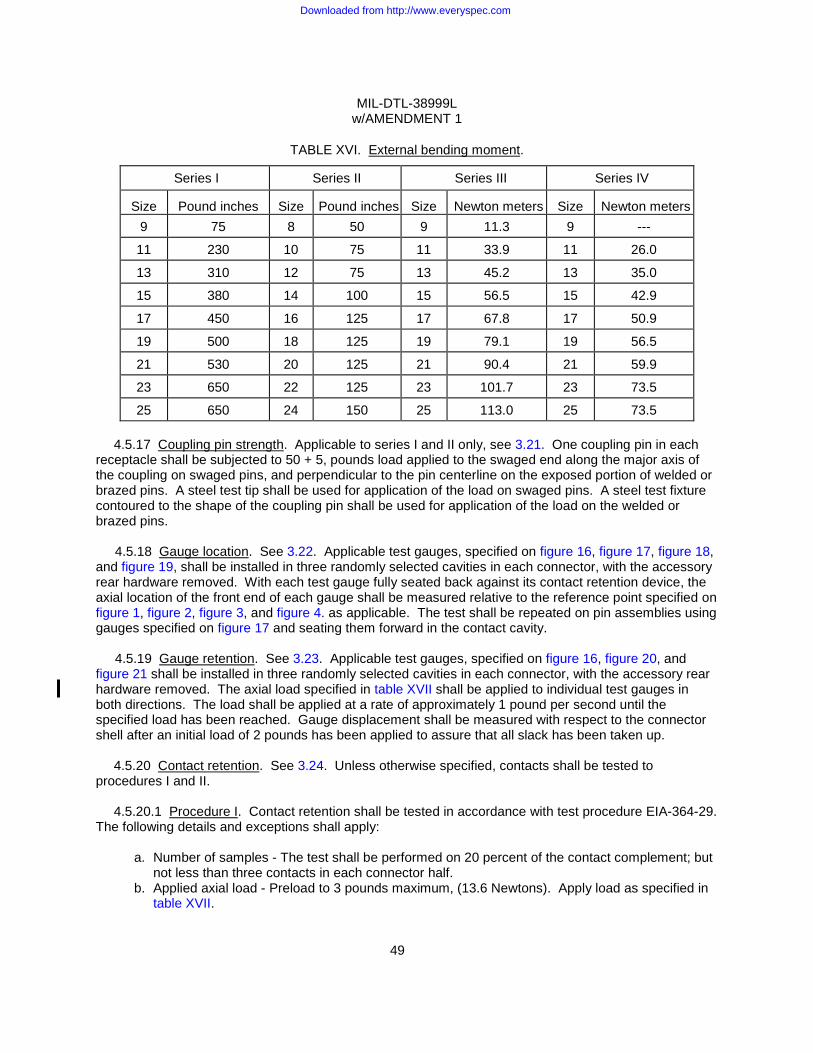
MIL-DTL-38999L w/AMENDMENT 1
49
TABLE XVI. External bending moment.
Series I Series II Series III Series IV
Size
Pound inches
Size Pound inches
Size
Newton meters
Size
Newton meters
9 75 8 50 9 11.3 9 ---
11 230 10 75 11 33.9 11 26.0
13 310 12 75 13 45.2 13 35.0
15 380 14 100 15 56.5 15 42.9
17 450 16 125 17 67.8 17 50.9
19 500 18 125 19 79.1 19 56.5
21 530 20 125 21 90.4 21 59.9
23 650 22 125 23 101.7 23 73.5
25 650 24 150 25 113.0 25 73.5
4.5.17 Coupling pin strength. Applicable to series I and II only, see 3.21. One coupling pin in each receptacle shall be subjected to 50 + 5, pounds load applied to the swaged end along the major axis of the coupling on swaged pins, and perpendicular to the pin centerline on the exposed portion of welded or brazed pins. A steel test tip shall be used for application of the load on swaged pins. A steel test fixture contoured to the shape of the coupling pin shall be used for application of the load on the welded or brazed pins.
4.5.18 Gauge location. See 3.22. Applicable test gauges, specified on figure 16, figure 17, figure 18, and figure 19, shall be installed in three randomly selected cavities in each connector, with the accessory rear hardware removed. With each test gauge fully seated back against its contact retention device, the axial location of the front end of each gauge shall be measured relative to the reference point specified on figure 1, figure 2, figure 3, and figure 4. as applicable. The test shall be repeated on pin assemblies using gauges specified on figure 17 and seating them forward in the contact cavity.
4.5.19 Gauge retention. See 3.23. Applicable test gauges, specified on figure 16, figure 20, and figure 21 shall be installed in three randomly selected cavities in each connector, with the accessory rear hardware removed. The axial load specified in table XVII shall be applied to individual test gauges in both directions. The load shall be applied at a rate of approximately 1 pound per second until the specified load has been reached. Gauge displacement shall be measured with respect to the connector shell after an initial load of 2 pounds has been applied to assure that all slack has been taken up.
4.5.20 Contact retention. See 3.24. Unless otherwise specified, contacts shall be tested to procedures I and II.
4.5.20.1 Procedure I. Contact retention shall be tested in accordance with test procedure EIA-364-29. The following details and exceptions shall apply:
a. Number of samples - The test shall be performed on 20 percent of the contact complement; but not less than three contacts in each connector half.
b. Applied axial load - Preload to 3 pounds maximum, (13.6 Newtons). Apply load as specified in table XVII.
Downloaded from http://www.everyspec.com
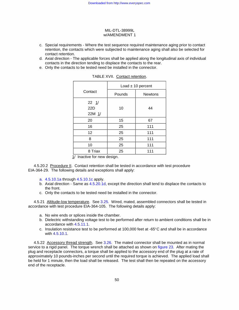
MIL-DTL-38999L w/AMENDMENT 1
50
c. Special requirements - Where the test sequence required maintenance aging prior to contact
retention, the contacts which were subjected to maintenance aging shall also be selected for contact retention.
d. Axial direction - The applicable forces shall be applied along the longitudinal axis of individual contacts in the direction tending to displace the contacts to the rear.
e. Only the contacts to be tested need be installed in the connector.
TABLE XVII. Contact retention.
Contact
Load ± 10 percent
Pounds
Newtons
22 1/ 22D 22M 1/
10
44
20 15 67 16 25 111 12 25 111 8 25 111
10 25 111 8 Triax 25 111
1/ Inactive for new design.
4.5.20.2 Procedure II. Contact retention shall be tested in accordance with test procedure EIA-364-29. The following details and exceptions shall apply:
a. 4.5.10.1a through 4.5.10.1c apply. b. Axial direction - Same as 4.5.20.1d, except the direction shall tend to displace the contacts to
the front. c. Only the contacts to be tested need be installed in the connector.
4.5.21 Altitude-low temperature. See 3.25. Wired, mated, assembled connectors shall be tested in
accordance with test procedure EIA-364-105. The following details apply:
a. No wire ends or splices inside the chamber. b. Dielectric withstanding voltage test to be performed after return to ambient conditions shall be in
accordance with 4.5.11.1. c. Insulation resistance test to be performed at 100,000 feet at -65°C and shall be in accordance
with 4.5.10.1.
4.5.22 Accessory thread strength. See 3.26. The mated connector shall be mounted as in normal service to a rigid panel. The torque wrench shall be attached as shown on figure 23. After mating the plug and receptacle connectors, a torque shall be applied to the accessory end of the plug at a rate of approximately 10 pounds-inches per second until the required torque is achieved. The applied load shall be held for 1 minute, then the load shall be released. The test shall then be repeated on the accessory end of the receptacle.
Downloaded from http://www.everyspec.com
MIL-DTL-38999L w/AMENDMENT 1
51
4.5.23 Vibration. Applicable at initial qualification testing only, see 3.27. Wired and mated connectors
shall be subjected to the applicable test(s) specified. Connectors shall be mounted on the vibration table by normal means. All contacts shall carry a test current of 100 milliamperes maximum and shall be continuously monitored for discontinuities throughout the test. A detector capable of detecting any discontinuities in excess of 1 microsecond shall be used. All series I and II connectors shall have the wire bundles clamped to fixed points at least 8 inches (203.2 mm) behind the connector. All series I, III, and IV plugs shall have an accessory load fixture specified on figure 24 attached during vibration.
4.5.23.1 Random vibration. Applicable to series II only. Connectors shall be tested in accordance with test procedure EIA-364-28. The following details shall apply:
a. Test condition VI, letter "I", except class Y shall be tested to letter "G". b. Duration shall be 8 hours in the longitudinal direction and 8 hours in a perpendicular direction
for a total of 16 hours. c. Means may be provided to relieve hermetic solder termination’s, and jumper wires may be used
between contacts.
4.5.23.2 Vibration. Applicable to series I, III and IV only. Connector samples shall be divided equally and subjected to vibration as specified:
a. Series I: Sine vibration (see 4.5.23.2.2). Random vibration (see 4.5.23.2.3). Random vibration (see 4.5.23.2.4).
b. Series III:
Sine vibration (see 4.5.23.2.1). Random vibration (see 4.5.23.2.3). Random vibration (see 4.5.23.2.4).
c. Series IV:
Sine vibration (see 4.5.23.2.2). Random vibration (see 4.5.23.2.3). Random vibration (see 4.5.23.2.4).
Means may be provided to relieve hermetic solder terminations, and jumper wires may be used between contacts.
4.5.23.2.1 Sine vibration. Applicable to series III only. Connector samples shall be subjected to a
simple harmonic motion from 10 to 2,000 Hz in each of three mutually perpendicular axes. The level of vibration shall be a velocity of 254 mm/sec from 10-50 Hz; 1.5 mm double amplitude from 50-140 Hz, and 60 G from 140-2,000 Hz. The entire frequency range from 10-2,000 Hz and back shall be traversed in 20 minutes. The vibration shall be applied for a duration of 12 hours in each of the three mutually perpendicular axes for a total of 36 hours. Each axis of vibration shall be accomplished by vibrating for 4 hours at ambient room temperature, 4 hours at -55°C ± 5°C, and 4 hours at +175°C ± 5°C for classes J, P, T, W, X, and Z, and 200°C ± 5°C for classes C, F, G, H, K, L, N, M, R, S, and Y.
4.5.23.2.2 Sine vibration. Applicable to series I and IV only. Connectors shall be subjected to the test specified in accordance with MIL-STD-202, procedure 204, test condition G.
Downloaded from http://www.everyspec.com
MIL-DTL-38999L w/AMENDMENT 1
52
4.5.23.2.3 Random vibration. Applicable to series I, III and IV only. Connectors shall be subjected to
the test specified in test procedure EIA-364-28. The following details shall apply:
a. Test condition VI - Letter "I". Series III at elevated temperature and series I and IV at ambient temperature, including verification of metal-to-metal shell bottoming for series III only (see 3.4.6.2.2). The verification of plug to receptacle metal-to-metal shell bottoming (or composite-to-composite shell bottoming) shall be accomplished by demonstrating that the connector meets a minimum rigidity requirement of 300 Hz (i.e. no resonances at frequencies less than 300 Hz). Two accelerometers, one for the perpendicular axis and one for the longitudinal axis (see figure 30), shall be placed on the backshell of the plug connector in the location as specified on figure 24 (dimension LL). Additionally, an input or control accelerometer shall be placed on a non-resonant point of the fixture to control the input vibration. If the accelerometers on the backshell indicate a resonance at a frequency below 300 Hz during any part of the vibration test procedures, the connector shall be considered to have failed (see 3.4.6.2.2). Verification of resonance shall be accomplished by monitoring the accelerometers placed on the backshell assembly. Prior to the random vibration test, a 2 g sinusoidal resonance search shall be performed to verify system response. During the random vibration test, the accelerometers data shall be recorded at 1 hour intervals. Following the random vibration test, the sinusoidal resonance search shall be performed again to verify any change in system resonance. In the case of the sinusoidal tests, resonance shall be defined as a response greater than twice the input vibration level. In the case of the random vibration test, resonance shall be defined as a response greater than four times the input vibration level (1g2 vs 4g2). Note: Lightweight accelerometers and mounting features shall be selected so that the total mass of the backshell/cable assembly shall be as specified on figure 24.
b. Vibration to be at the following temperatures:
(1) Series III, classes J, P, T, W, X, and Z: 175°C ± 5°C, classes C, F, G, H, K, L, M, N, R, S and Y: 200°C ± 5°C. (2) Series I and IV: Ambient temperature.
c. Duration shall be 8 hours in the longitudinal direction and 8 hours in a perpendicular direction for a total of 16 hours for classes C, E, F, G, J, K, L, M, N, P, R, S, T, W, X and Z. Duration shall be 4 hours in the longitudinal direction and 4 hours in a perpendicular direction for a total of 8 hours for classes H, Y, and N hermetic receptacles.
4.5.23.2.4 Random vibration. Applicable to series I, III and IV only. Connectors shall be tested in
accordance with test procedure EIA-364-28. The following details shall apply:
a. Test condition V - Using the vibration envelope shown on figure 25. b. Vibration to be conducted at ambient temperature. c. Duration shall be 8 hours in the longitudinal direction and 8 hours in a perpendicular direction
for a total of 16 hours. d. Figure 24 test accessory shall not be required.
4.5.24 Shock. See 3.28. Wired and mated connectors shall be subjected to the applicable test
specified. Connectors shall be mounted by normal means and held together by normal coupling means. All contacts shall be wired in a series circuit with 100 milliamperes maximum current flow through the series circuit during shock. Connectors shall be monitored for any discontinuities. A detector capable of detecting all discontinuities in excess of 1 microsecond shall be used.
Downloaded from http://www.everyspec.com

MIL-DTL-38999L w/AMENDMENT 1
53
4.5.24.1 Standard shock (all series). Connectors shall be tested in accordance with test procedure
EIA-364-27. The following details shall apply:
a. The pulse shall be an approximate half sine wave of 300 G ± 15 percent magnitude with a duration of 3 ± 1 milliseconds.
b. The wire bundle shall be clamped to fixed points at least 8 inches (203.2 mm) from the rear of the connector.
4.5.24.2 High-impact shock. Applicable to series I, III and IV only. Wired and mated connectors shall
be tested in accordance with MIL-S-901, grade A with the following modifications and additions. Mounting fixture shall be in accordance with MIL-S-901, light weight. The wire bundle shall be supported on a stationary frame in such a manner to provide a free flexing length between the frame and fixture of not less than 36 inches (914.4 mm). Each plug shall be terminated with at least 80 percent of wired contacts. The wire bundle shall be provided with a straight, environmental, backshell, category 2B in accordance with SAE-AS85049, the longest length available per shell size.
4.5.25 Shell-to-shell conductivity. Applicable to all classes and finishes except class C and finish C, see 3.29. Mated connectors shall be tested in accordance with test procedure EIA-364-83.
4.5.25.1 Backshell shield braid-to-shell conductivity. Applicable to Series III only, all classes and
finishes, see 3.29.1. Mated connectors shall be tested in accordance with test procedure EIA-364-83, except that measurement shall be made between the plug backshell’s shield braid and either the accessory threads or mounting flange of the receptacle (see figure 31 for test setup). A backshell in accordance with SAE-AS85049 shall be utilized.
4.5.26 Humidity. See 3.30. Wired, mated connectors shall be tested in accordance with test procedure EIA-364-31. The following details and exceptions shall apply:
a. Test method IV. b. The mated connectors shall be mounted in a vertical position. c. DELETED. d. Three hours minimum after the start of step 7a during the final cycle and while the connectors
are still subjected to high humidity, insulation resistance and dielectric withstanding voltage shall be measured when the chamber temperature reaches 20°C ± 5°C and condensation is observed on the connector.
e. For qualification testing, insulation resistance readings shall be made on a minimum of 50 percent of the circuits. Outer circuits shall be measured to the connector shell.
4.5.27 Shell spring finger forces. See 3.31. Plugs shall be completely mated and unmated 10 times
with counterpart receptacles less coupling pins (if applicable) and inserts. On the mating of the first cycle, the forces necessary to engage the connectors shall be within the values specified in table V. On the unmating of the last cycle, the forces necessary to separate the connectors shall be within the value specified in table V. When measuring the engagement and separation forces, the axial loads shall be applied at a displacement rate of 0.5 inches per minute.
4.5.28 EMI shielding. Applicable to all classes and finishes except class C and finish C, see 3.32.
Downloaded from http://www.everyspec.com
MIL-DTL-38999L w/AMENDMENT 1
54
4.5.28.1 EMI shielding, low frequencies. Applicable frequency range is 100 to 1,000 MHz only. The
EMI shielding effectiveness of mated connectors with EMI backshells (backshells may be soldered to the connector) shall be measured in a triaxial radio frequency leakage fixture as shown on figure 26. The EMI leakage from the conductor inside the connector in the same inner coaxial line into the outer coaxial line shall be measured at the frequencies specified in table VIII within a frequency accuracy of ±5 percent. The level of detected signal power shall be specified by a tunable radio frequency field intensity meter isolated from the test circuit by a 3 to 10 dB pad. Care shall be taken to ensure that the signal is a result of EMI leakage from within the mated connector and not due to a faulty termination inside the fixture. All terminations inside the fixture, whether to the EMI backshells or between internal conductors, shall have a leakage at least 10 dB less than the test requirements. The signal source shall be set to the desired frequency. The signal shall be fed through a 3 to 10 dB isolation pad to a parallel circuit consisting of a coaxial switch (DPDT) so connected that the signal can be manually or electronically fed alternately to the fixture and to a variable 100 dB reference attenuator. The attenuator shall be adjustable in 1 dB steps and calibrated to ± 3 dB.
a. The inserts may be removed from the connectors under test or the contacts removed and a hole drilled through the inserts to accommodate a center conductor of suitable geometry to provide a good 50-ohms impedance match with the inside diameter of the mated connector shells and EMI backshells. Tapered transition may be used to provide a means of changing diameters without introducing significant discontinuities in the line. The maximum voltage standing wave ratio (VSWR) in the inner coaxial line shall be 1.5. The outer shell of the test fixture shall be so constructed as to provide a good 50-ohms impedance match with the outside diameter of the mated connector shells, coupling ring, and EMI backshells. The maximum VSWR of the outer coaxial line shall be 1.5.
b. A sliding circumferential short shall be positioned behind the connector on the signal input end
of the fixture to provide for tuning the outer coaxial line for maximum output at each test frequency. The allowable travel of this short shall be greater than 1/2 wave length at the lowest test frequency of 1.5 meters minimum for 100 MHz. The inner coaxial line shall be terminated in a fixed 50-ohms load impedance behind the connector at the output end of the fixture.
c. The connectors used to couple together the various elements of the test system shall be of a
low-leakage type which have a nominal impedance of 50 ohms, a VSWR of less than 1.5, and a minimum leakage attenuation of 100 dB. The output impedance of the signal source and the input impedance of the detector shall be nominally 50 ohms with a maximum VSWR of 1.5. The input and output VSWR of the standard attenuator shall be less than 1.5 in the 20 to 100 dB range.
d. The relative signal level in the variable attenuator shall be equaled to the signal level through
the leakage fixture by adjusting the attenuator. The signal loss in the fixture can then be read from the setting on the variable attenuator.
4.5.28.2 EMI shielding, high frequencies. Applicable frequency range is 1,000 to 10,000 MHz only.
The EMI shielding effectiveness of mated connectors with EMI backshells shall be measured using the mode-stirred technique in accordance with test procedure EIA-364-66.
4.5.29 Ozone exposure. See 3.33. Wired, mated connectors shall be tested in accordance with test procedure EIA-364-14.
Downloaded from http://www.everyspec.com
MIL-DTL-38999L w/AMENDMENT 1
55
4.5.30 Fluid immersion. Initial qualification, see 3.34. Connector samples shall be tested in
accordance with test procedure EIA-364-10 (one sample per fluid). Following the fluid immersion cycles, the connectors shall be tested for coupling torque in accordance with 4.5.7 and dielectric withstanding voltage at sea level in accordance with 4.5.11.1 within 3 hours.
4.5.30.1 Retention system fluid immersion. See 3.34.1. Unmated connectors with contacts removed shall be immersed in the fluids in accordance with test procedure EIA-364-10 (one sample per fluid) for 2 hours at room temperature. After removal, excess fluid shall drain from the connectors for 4 hours and the contacts reinstalled. Following the test, the connectors shall be subjected to contact retention as specified in 4.5.20.
4.5.31 Pin contact stability. See 3.35. The unmated connectors shall have 10 percent of their pin contacts subjected to this test. Gauge pins conforming dimensionally to the requirements on figure 16 shall be used. The connector shall be held in a holding device. The forces specified in table IX shall be applied to the exposed rod as shown on figure 27. The load shall be applied gradually at a rate not exceeding 1 inch (25.4 mm) per minute. The total pin tip displacement shall be measured as shown on figure 27.
4.5.32 Contact walkout. See 3.36. Two contacts in each plug and receptacle shall be tested. The contacts shall be crimped to stranded steel cable of an appropriate size and installed in the connector. The unmated connector shall be mounted in a test fixture as shown on figure 28. A 3-pound load shall be applied to the cable. One 360° rotation of the fixture with the connector mounted shall constitute one cycle. The connector shall be subjected to 100 cycles at a rate of 10 to 20 cycles per minute.
4.5.33 Installing and removal tool abuse. Applicable at initial qualification only, see 3.37. Five contact cavities in each connector shall be subjected to each of the following tests. Different contact cavities shall be used for each test. Should a tool become damaged during any of the testing, it shall be replaced. Failure of a tool shall not constitute a test failure. Tools shall be utilized in accordance with MIL-I-81969/14.
4.5.33.1 Removal tool rotation. The tool shall be inserted as if to remove a contact and a total of 3 pounds axial load shall be applied. With the force applied, the tool shall be rotated 180° and then removed also removing the contact. The contact shall be reinserted. The steps shall be repeated three times on each of five contacts selected.
4.5.34 High temperature exposure.
4.5.34.1 High temperature exposure with contact loading. See 3.38.1. Connectors with removable contacts shall have one mating pair of contacts removed from an untested contact cavity and replaced with contacts crimped or otherwise attached to steel cable or steel-cored copper wire (copper-weld, or equivalent) of an appropriate size. The axial location of these contacts shall be measured for conformance to the applicable dimensions on figure 1, figure 2, figure 3, and figure 4, as applicable, with a load of approximately 2 pounds applied to seat the contact back against the retention device. The connector shall then be mounted in a fixture equivalent as shown on figure 29. A weight equal to 50 percent of the axial load specified in table XVII for the applicable contact size shall be suspended freely from each steel wire.
Downloaded from http://www.everyspec.com
MIL-DTL-38999L w/AMENDMENT 1
56
A current of 100 milliamperes maximum shall be applied to the test contacts and a suitable instrument
shall be used to monitor the circuit for discontinuities in excess of 1 microsecond. The mounted connector shall then be exposed to 150°C for finish A of series I and II, 175°C for finishes B and X of series I and II, and classes J, P, T, W, X and Z of series III and IV, and 200°C for all other finishes and classes for 1,000 hours minimum. After the connectors return to ambient temperature, they shall be unmated and the contact locations shall be remeasured with approximately 2 pounds axial load applied to seat the contact back against the retention device.
4.5.34.2 High temperature exposure. Applicable to all classes of series III except hermetic connectors, see 3.38.2. Mated connectors shall be subjected to an ambient temperature of 175°C + 3°C, - 0°C for classes J, P, T, W, X and Z, and 200°C + 3°C, -0°C for all other classes. The temperature shall be maintained for 1,000 hours.
4.5.35 Electrolytic erosion. Applicable to all classes of series III and IV, see 3.39. The wired receptacle half of the connector containing the pin contacts shall be firmly mounted in a vertical position pins facing up. A salt-water solution (5 percent salt by weight) shall be poured onto the pin interface until the solution level just reaches the pin tips. The solution shall remain in the connector for a minimum of 30 seconds and then poured out, lightly shaking excesses from the connector. The counterpart plug shall immediately be mated with the receptacle. One cell pattern, with all contacts adjacent to a central contact at a positive polarity and the center contact at a negative polarity, shall be set up at a location giving the most uniform distribution of contacts adjacent to the center contact. A potential of 60 volts dc shall be applied between the contacts adjacent to the center contact. The contacts shall be energized for 40 hours. Following this, with the voltage disconnected, the connectors shall be unmated and the pin contacts removed (except for hermetics). The contacts shall be examined under three power (3X) magnification for erosion to base metal.
4.5.36 Firewall. Applicable to classes K and S connectors only, see 3.40. The mated, torqued, and wired connectors shall be tested in accordance with test procedure EIA-364-45. The following detail and exception shall apply: Wire bundles to be clamped to fixed points at least 8 inches (203.2 mm) behind the connector.
4.5.37 Contact plating thickness. Applicable to hermetic connectors only, see 3.41. Measurement shall be made on the external surface of the contact .100 to .150 inches (2.54 to 3.81 mm) from end of mating end. Contact plating thickness shall be measured by any procedure which will give results within ± 10 percent of the true thickness.
4.5.38 Contact engagement and separating force. Applicable to hermetic connectors with sockets only, see 3.42. Contact engagement and separating force shall be measured as specified in SAE-AS39029.
4.5.39 Resistance to probe damage. Applicable to hermetic connectors with sockets only, see 3.43. Resistance to probe damage shall be performed as specified in SAE-AS39029, except contacts shall be installed in connector.
4.5.40 Ice resistance. Applicable to all classes under series I, III and IV, see 3.44. Mated connectors shall be immersed in tap water for 1 minute and then placed in an ambience of - 65° C for 1 hour. A minimum of three such cycles shall be performed until the connector surfaces are completely iced over. Immediately after removal from the last cycle, the frozen connectors shall be uncoupled and then recoupled. The connectors shall be uncoupled and recoupled a second time with the uncoupling and coupling torque measured in accordance with 4.5.7. The uncoupling and coupling torque shall not be measured on the first uncoupling and recoupling.
Downloaded from http://www.everyspec.com
MIL-DTL-38999L w/AMENDMENT 1
57
4.5.41 Dust (fine sand). Applicable to all classes under series I, III and IV, see 3.45. Mated connectors shall be tested in accordance with procedure 110 of MIL-STD-202.
4.5.42 Thermal vacuum outgassing. Applicable to classes G and H for initial qualifications only, see
3.46. All materials used in the finished connector shall be tested in accordance with ASTM E595. Samples to be tested shall have been processed in the same manner as that used in production of the qualification lot.
4.5.43 Hydrolytic stability (classes J and M). Initial qualification, see 3.47. Mated connectors less
inserts shall be subjected to the following water absorption test (connectors shall be unplated). The connectors shall be tested in accordance with ASTM D570 for long-term immersion.
4.5.43.1 DELETED.
4.5.43.2 DELETED.
4.5.44 Cavity-to-cavity leakage bonding integrity. See 3.48. Unmated connectors shall be tested in accordance with test procedure EIA-364-78.
4.5.45 Impact. Applicable to classes J and M only, see 3.49. Connector plugs with SAE-AS85049 straight strain relief clamps shall be tested in accordance with test procedure EIA-364-42. The following conditions apply.
a. Drop height shall be 4 feet (1.219 meters). b. Number of drops shall be 8. c. Plate shall be indexed at 36° intervals. d. Plugs shall have no caps or covers installed.
4.5.46 Insert bond strength. See 3.50. The connector’s bonded insert assembly shall be tested in
accordance with test procedure EIA-364-79.
4.5.47 Resistance to indirect lightning strike. See 3.51. Series III only, all classes. Mated connectors as specified in test procedure EIA/ECA-364-75 shall be tested in accordance with test procedure EIA/ECA-364-75 with the following details and exceptions:
a. Test sequence shall be as specified in table XII, group 14. b. Each specimen shall be subjected to three current pulses in each polarity (a total of six
pulses). After each current pulse, the connectors shall be unscrewed ½ turn counter-clockwise without removing or unmating in order to break any weld points that may have occurred. Connectors shall then be re-tightened ½ turn, back to the fully mated position.
c. Visual examination shall be conducted under three-five power (3-5X) magnification in accordance with test procedure EIA/ECA-364-75.
d. Coupling torque shall be in accordance with 4.5.7. e. Shell-to-shell conductivity testing shall be in accordance with 4.5.25.1. f. The peak current, Ipk, shall be as specified in table XVIII. g. Insulation resistance at ambient temperature shall be in accordance with 4.5.10.1, followed
by dielectric withstanding voltage at sea level in accordance with 4.5.11.1. h. The waveform for indirect lightning strike effects, as specified on figure 32, shall be utilized.
Downloaded from http://www.everyspec.com
MIL-DTL-38999L w/AMENDMENT 1
58
TABLE XVIII. Resistance to indirect lightning strike test currents.
Connector class Peak current (Amps)
Class C not applicable Classes F, G, H, K, L, P, R, T, S, X, W, Y and Z 10,000 Classes J and M (shell sizes 11 and larger) 6,000 Classes J and M (shell sizes 9) 3,000
4.5.48 Magnetic permeability. See 3.3.4. Connectors shall be tested in accordance with test
procedure EIA-364-54.
4.5.49 Post test examination. The tested connectors and contacts shall be examined for compliance with 3.52 and 3.53 to determine the effects of previous testing. Any evidence of cracking, loosening of parts, carbon tracking, excess wear, or missing parts shall be recorded.
5. PACKAGING
5.1 Packaging. For acquisition purposes, the packaging requirements shall be as specified in the contract or order (see 6.2). When actual packaging of materiel is to be performed by DoD or in-house contractor personnel, these personnel need to contact the responsible packaging activity to ascertain packaging requirements. Packaging requirements are maintained by the Inventory Control Point's packaging activities within the Military Department or Defense Agency, or within the military service’s system commands. Packaging data retrieval is available from the managing Military Department's or Defense Agency's automated packaging files, CD-ROM products, or by contacting the responsible packaging activity.
6. NOTES (This section contains information of a general or explanatory nature that may be helpful, but is not mandatory.)
6.1 Intended use. The various configurations of the connectors are intended for use as follows:
a. Series I connectors: General application within weapon system where a quick disconnect coupling system is required for blind mating or other mating problem areas. These connectors provide high-vibration characteristics and are suitable for severe wind and moisture problem (SWAMP) areas with proper connector accessories.
Class G, finish F: Provides a conductive shell for EMI considerations but with additional requirements for space grade applications. Class H: Same as class Y, but with additional requirements for space grade applications. Class T, finish F: Provides a conductive shell for EMI considerations. Class Y: Applications where pressure must be maintained. Classes R, U and X: Applications requiring high corrosion resistance.
b. Series II connectors: General application within weapon systems which are not subjected to high vibration or SWAMP areas. These connectors are not scoop proof (see 6.1.1). Connectors are light weight.
Downloaded from http://www.everyspec.com
MIL-DTL-38999L w/AMENDMENT 1
59
c. Series III connectors: General application within weapons systems and are suitable for blind
mating areas. These connectors provide high-vibration characteristics at elevated temperature and are suitable for SWAMP areas with the proper connector accessories.
Class W - Provides a corrosion resistance shell. Class F - Provides a conductive shell for EMI requirements. Class K - Provides a stainless steel firewall connector for engine applications. Class L - Provides a stainless steel connector for general applications. Class S - Provides a stainless steel firewall connector with enhanced EMI performance. Class Y - Applications where pressure must be maintained. Class J - Provides a corrosion resistant, lightweight composite shell with conductivity
equivalent to class W. Class M - Provides a corrosion resistant, lightweight composite connector with conductive
plating for EMI performance equivalent to class F. Class G - Same as class F but additional requirements for space grade applications. Class H - Same as class Y but additional requirements for space grade applications. Classes R and X - Applications requiring high corrosion resistance (for metallic shells). Classes P, T and Z - Applications requiring alternatives to cadmium plating.
d. Series IV connectors: General application within weapons systems where a quick disconnect coupling system is required for blind mating or other mating problem areas. These connectors provide high-vibration characteristics and are suitable for SWAMP areas with the proper connector accessories.
Classes W, F, G, H, J, M, and Y: Same as series III. Classes R and X: Applications requiring high corrosion resistance. Classes P, T and Z: Applications requiring alternatives to cadmium plating.
e. Series I and II are intermateable with series I and II as specified in MIL-DTL-27599.
6.1.1 Application guidance.
a. Users of connectors covered by this specification, in new design systems and support
equipment are advised to evaluate carefully for each application the relative merits of the long shell series I, III, IV, and short shell series II connectors. When considering use of the short shell series II connectors, the following areas must be evaluated:
(1) Series II connectors are vulnerable to pin contact bending from scooping, with contact
size 22 being the most vulnerable.
(2) Use of series II connectors must be avoided in areas of blind mating.
(3) Receptacles must be located so as to minimize the amount of required cable bending. When using series II connectors with large cables which must be bent at right angles, the cables must have the right angle bend permanently established.
(4) Series II connector should not be used with heavy jacketed cable and excessive overhang
moments, because of possible shell damage.
(5) Series II connectors should not be used in areas of rough handling such as experienced near engine removal, generators, support equipment, or portable equipment, etc.
Downloaded from http://www.everyspec.com
MIL-DTL-38999L w/AMENDMENT 1
60
(6) When mating series II connectors in areas of difficult visibility, care must be exercised to
make sure that all bayonet pins are engaged by the coupling ring, since it is possible to engage only one bayonet pin and therefore only partially couple.
(7) When mating series II connectors in areas of difficult visibility, care must be exercised to
make sure that connector plugs with pins are not coupled to receptacles with pins. This situation will result in the contacts touching.
b. When the use of series IV connectors is considered, the design of the coupling system should
be evaluated. If the coupling mechanism between the coupling ring and the shell is not properly positioned prior to the mating operation, the coupling ring must be repositioned prior to mating.
c. Series I and II, class P connectors should not be used in Air Force new design applications,
except when specifically approved by the procuring activity.
d. Application restrictions concerning the use of these connectors are set forth in MIL-STD-1353.
e. Recommended panel cutout dimensions are shown on figure 11.
f. Compatibility of connectors should be addressed when intermating different classes and finishes. Galvanically incompatible classes and finishes should not be intermated together. When intermating classes with different performance requirements, the lower performance requirements of the two classes apply.
g. Composite class connectors should be considered for applications requiring increased corrosion
resistance, increased durability, or decreased weight.
h. Box mount connectors are intended to be used on environmentally sealed boxes. If full wire sealing capability is needed a wall mount or jam-nut mount connector should be used.
i. A summary of shell materials and finishes for each series is listed in table XIX.
j. For environment resisting classes, wire sealing for contact size 8 may be accomplished by the
use of separate resilient bushings that are furnished with the connector (see 3.4.2.1). If size 8 contacts with separate resilient bushings are replaced, it is recommended that the bushings be retained for use with the new contacts.
k. Classes P and T are required to be nonreflective. Finish W is required to be an olive drab color
in accordance with SAE-AMS-QQ-P-416 and class Z is required to be black in accordance with ASTM B841 (see 3.3.6.4). These nonreflective finishes and colors may vary in color depending on the method of manufacture. This variance in color does not alter the performance capabilities of the finish.
Downloaded from http://www.everyspec.com
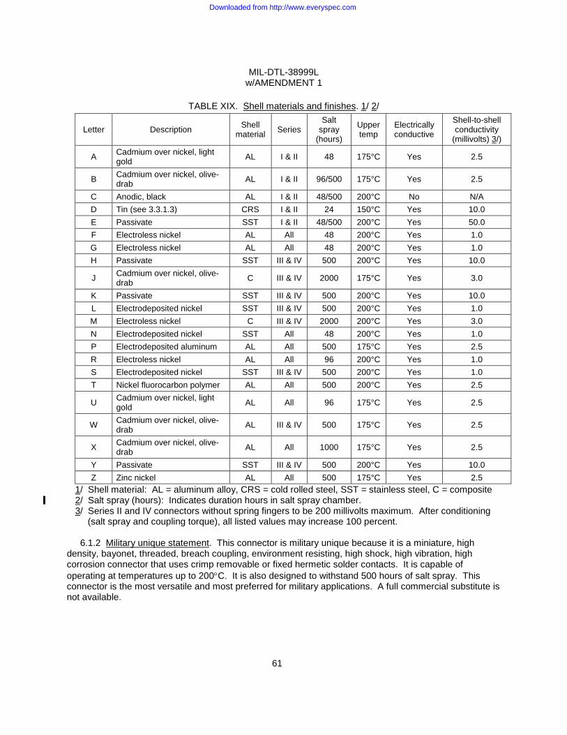
MIL-DTL-38999L w/AMENDMENT 1
61
TABLE XIX. Shell materials and finishes. 1/ 2/
Letter Description Shell material Series
Salt spray
(hours)
Upper temp
Electrically conductive
Shell-to-shell conductivity
(millivolts) 3/)
A Cadmium over nickel, light gold AL I & II 48 175°C Yes 2.5
B Cadmium over nickel, olive-drab AL I & II 96/500 175°C Yes 2.5
C Anodic, black AL I & II 48/500 200°C No N/A D Tin (see 3.3.1.3) CRS I & II 24 150°C Yes 10.0 E Passivate SST I & II 48/500 200°C Yes 50.0 F Electroless nickel AL All 48 200°C Yes 1.0 G Electroless nickel AL All 48 200°C Yes 1.0 H Passivate SST III & IV 500 200°C Yes 10.0
J Cadmium over nickel, olive-drab C III & IV 2000 175°C Yes 3.0
K Passivate SST III & IV 500 200°C Yes 10.0 L Electrodeposited nickel SST III & IV 500 200°C Yes 1.0 M Electroless nickel C III & IV 2000 200°C Yes 3.0 N Electrodeposited nickel SST All 48 200°C Yes 1.0 P Electrodeposited aluminum AL All 500 175°C Yes 2.5 R Electroless nickel AL All 96 200°C Yes 1.0 S Electrodeposited nickel SST III & IV 500 200°C Yes 1.0 T Nickel fluorocarbon polymer AL All 500 200°C Yes 2.5
U Cadmium over nickel, light gold AL All 96 175°C Yes 2.5
W Cadmium over nickel, olive-drab AL III & IV 500 175°C Yes 2.5
X Cadmium over nickel, olive-drab AL All 1000 175°C Yes 2.5
Y Passivate SST III & IV 500 200°C Yes 10.0 Z Zinc nickel AL All 500 175°C Yes 2.5
1/ Shell material: AL = aluminum alloy, CRS = cold rolled steel, SST = stainless steel, C = composite 2/ Salt spray (hours): Indicates duration hours in salt spray chamber. 3/ Series II and IV connectors without spring fingers to be 200 millivolts maximum. After conditioning
(salt spray and coupling torque), all listed values may increase 100 percent.
6.1.2 Military unique statement. This connector is military unique because it is a miniature, high density, bayonet, threaded, breach coupling, environment resisting, high shock, high vibration, high corrosion connector that uses crimp removable or fixed hermetic solder contacts. It is capable of operating at temperatures up to 200°C. It is also designed to withstand 500 hours of salt spray. This connector is the most versatile and most preferred for military applications. A full commercial substitute is not available.
Downloaded from http://www.everyspec.com
MIL-DTL-38999L w/AMENDMENT 1
62
6.2 Acquisition requirements. Acquisition documents should specify the following:
a. Title, number, and date of the specification. b. DELETED. c. Packaging requirements (see 5.1). d. Nomenclature by class, type, finish, style, size, and PIN (see 1.3.1 and 3.52). e. Whether contacts, sealing plugs, and tools are included (see 1.3.1e, 3.4.1, 3.4.1.2, 3.4.1.4, and
3.4.3.2).
6.3 Qualification. With respect to products requiring qualification, awards will be made only for products which are, at the time of award of contract, qualified for inclusion in Qualified Product List QPL No. 38999 whether or not such products have actually been so listed by that date. The attention of the contractors is called to these requirements, and manufacturers are urged to arrange to have the products that they propose to offer to the Federal Government tested for qualification in order that they may be eligible to be awarded contracts or orders for the products covered by this specification. Information pertaining to qualification of products may be obtained from the Defense Supply Center Columbus, DSCC-VQ, 3990 East Broad Street, Columbus, Ohio 43218-3990. An online listing of products qualified to this specification may be found in the Qualified Products Database (QPD) at http://assist.daps.dla.mil.
6.3.1 Copies of "Provisions Governing Qualification SD-6". Copies of "Provisions Governing
Qualification SD-6" may be obtained upon application to Defense Printing Service Detachment Office, Bldg. 4D (Customer Service), 700 Robbins Avenue, Philadelphia, PA 19111-5094.
6.4 Definitions.
Blind-mate: A situation in which personnel wishing to mate a connector can neither see nor
touch the connector halves being mated and must rely on some mechanism to accomplish the mating.
Scoop-proof: Scoop-proof means that because of the connector long shell design, it is
impossible for the mating plug connector to inadvertently be cocked into the mating receptacle and damage the pins or electrically short the contacts.
Space grade: Connectors that are classed as space grade are those connectors that are nickel
plated and meet the outgassing requirements as specified here. Cadmium or tin finishes are not allowed for space applications.
6.5 Applicable contacts. Table XX lists applicable pin and socket contacts for series I, II, II and IV.
Downloaded from http://www.everyspec.com
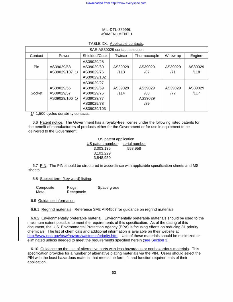
MIL-DTL-38999L w/AMENDMENT 1
63
TABLE XX. Applicable contacts. SAE-AS39029 contact selection
Contact Power Shielded/Coax Twinax Thermocouple Wirewrap Engine
Pin
AS39029/58 AS39029/107 1/
AS39029/28 AS39029/60 AS39029/76 AS39029/102
AS39029
/113
AS39029
/87
AS39029
/71
AS39029
/118
Socket
AS39029/56 AS39029/57 AS39029/106 1/
AS39029/27 AS39029/59 AS39029/75 AS39029/77 AS39029/78 AS39029/103
AS39029
/114
AS39029
/88 AS39029
/89
AS39029
/72
AS39029
/117
1/ 1,500 cycles durability contacts.
6.6 Patent notice. The Government has a royalty-free license under the following listed patents for the benefit of manufacturers of products either for the Government or for use in equipment to be delivered to the Government.
US patent application
US patent number serial number 3,003,135 558,958 3,101,229 3,848,950
6.7 PIN. The PIN should be structured in accordance with applicable specification sheets and MS
sheets. 6.8 Subject term (key word) listing. Composite Plugs Space grade Metal Receptacle
6.9 Guidance information.
6.9.1 Regrind materials. Reference SAE AIR4567 for guidance on regrind materials. 6.9.2 Environmentally preferable material. Environmentally preferable materials should be used to the
maximum extent possible to meet the requirements of this specification. As of the dating of this document, the U.S. Environmental Protection Agency (EPA) is focusing efforts on reducing 31 priority chemicals. The list of chemicals and additional information is available on their website at http://www.epa.gov/osw/hazard/wastemin/priority.htm. Use of these materials should be minimized or eliminated unless needed to meet the requirements specified herein (see Section 3).
6.10 Guidance on the use of alternative parts with less hazardous or nonhazardous materials. This
specification provides for a number of alternative plating materials via the PIN. Users should select the PIN with the least hazardous material that meets the form, fit and function requirements of their application.
Downloaded from http://www.everyspec.com
MIL-DTL-38999L w/AMENDMENT 1
64
6.11 Guidance on performance determination of connectors. Users and suppliers of connectors should
be cognizant of the fact that the lowest performing member of a connector assembly, determines the performance characteristics of the connector. Certain combinations of connector components can be selected in the PIN system of the document in such a manner as to create a connector with degraded performance. Following are just a few of the examples:
a. D38999/26KJ20PN, is a series III stainless steel plug with twin axial and coaxial contacts that may not meet the firewall requirement of the specification.
b. D38999/26KJ61HN, is a series III stainless steel plug with high durability contacts. However, the connector will be limited to 500 cycles of durability.
c. Insert arrangements using multi-axial (i.e. coax, twinax, triax, shielded) contacts should not be used in firewall applications.
6.12 Tin whisker growth. The use of alloys with tin content greater than 97 percent, by mass, may
exhibit tin whisker growth problems after manufacture. Tin whiskers may occur anytime from a day to years after manufacture and can develop under typical operating conditions, on products that use such materials. Conformal coatings applied over top of a whisker-prone surface will not prevent the formation of tin whiskers. Alloys of 3 percent lead, by mass, have shown to inhibit the growth of tin whiskers. For additional information on this matter, refer to ASTM B545 (Standard Specification for Electrodeposited Coatings of Tin) (see 3.3.1.3). 6.13 Amendment notations. The margins of this specification are marked with vertical lines to indicate modifications generated by the amendment. This was done as a convenience only and the Government assumes no liability whatsoever for any inaccuracies in these notations. Bidders and contractors are cautioned to evaluate the requirements of this document based on the entire content irrespective of the marginal notations.
Downloaded from http://www.everyspec.com
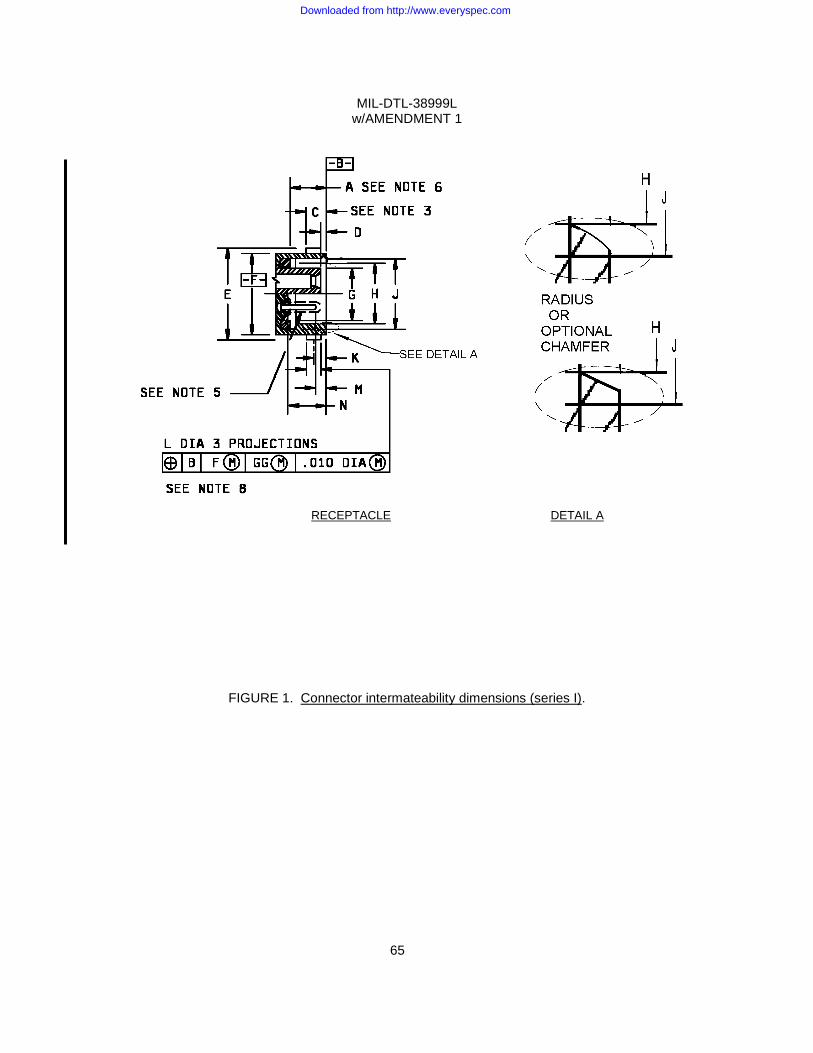
MIL-DTL-38999L w/AMENDMENT 1
65
RECEPTACLE DETAIL A
FIGURE 1. Connector intermateability dimensions (series I).
Downloaded from http://www.everyspec.com
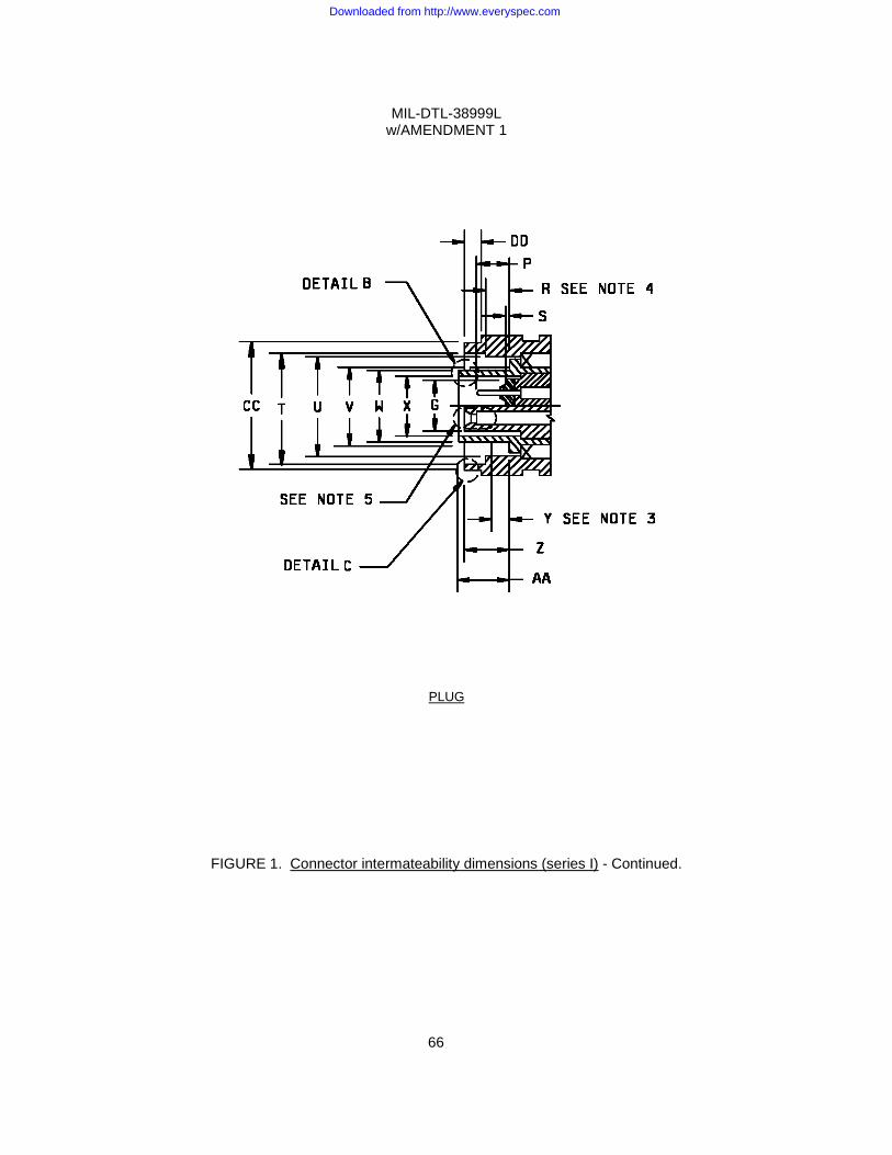
MIL-DTL-38999L w/AMENDMENT 1
66
PLUG
FIGURE 1. Connector intermateability dimensions (series I) - Continued.
Downloaded from http://www.everyspec.com
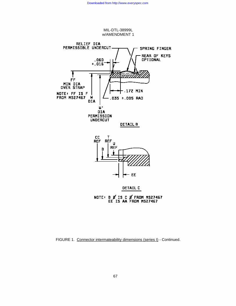
MIL-DTL-38999L w/AMENDMENT 1
67
FIGURE 1. Connector intermateability dimensions (series I) - Continued.
Downloaded from http://www.everyspec.com
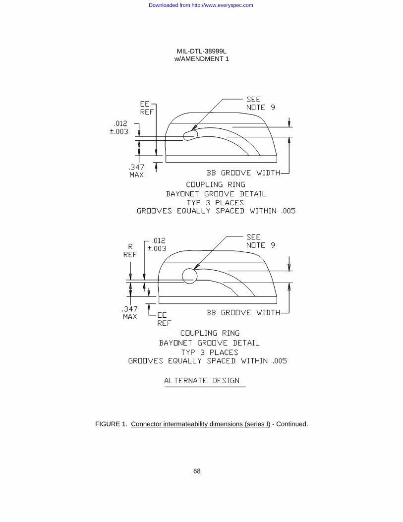
MIL-DTL-38999L w/AMENDMENT 1
68
FIGURE 1. Connector intermateability dimensions (series I) - Continued.
Downloaded from http://www.everyspec.com
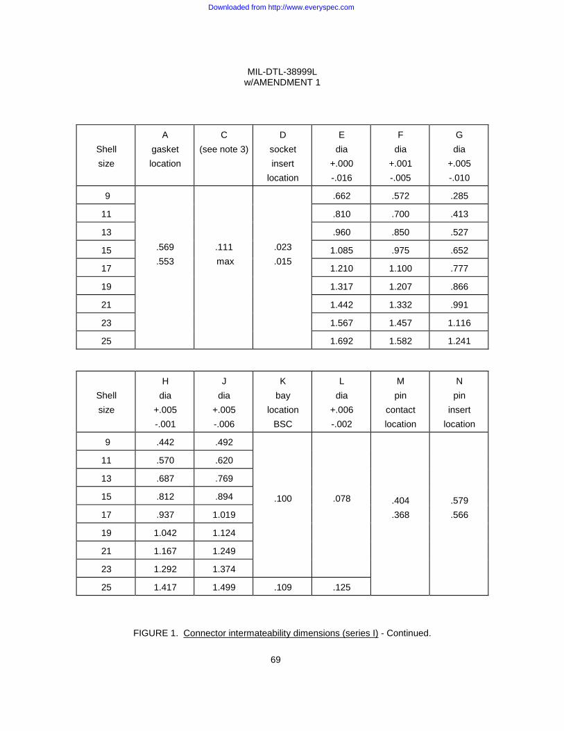
MIL-DTL-38999L w/AMENDMENT 1
69
Shell size
A gasket location
C (see note 3)
D socket insert
location
E dia
+.000 -.016
F dia
+.001 -.005
G dia
+.005 -.010
9
.569 .553
.111 max
.023 .015
.662 .572 .285
11 .810 .700 .413
13 .960 .850 .527
15 1.085 .975 .652
17 1.210 1.100 .777
19 1.317 1.207 .866
21 1.442 1.332 .991
23 1.567 1.457 1.116
25 1.692 1.582 1.241
Shell size
H dia
+.005 -.001
J dia
+.005 -.006
K bay
location BSC
L dia
+.006 -.002
M pin
contact location
N pin
insert location
9 .442 .492
.100
.078
.404 .368
.579 .566
11 .570 .620
13 .687 .769
15 .812 .894
17 .937 1.019
19 1.042 1.124
21 1.167 1.249
23 1.292 1.374
25 1.417 1.499 .109 .125
FIGURE 1. Connector intermateability dimensions (series I) - Continued.
Downloaded from http://www.everyspec.com

MIL-DTL-38999L w/AMENDMENT 1
70
Shell size
P pin
contact location
R (see note 4)
S pin
insert location
T dia
+.005 -.006
U dia
+.005 -.001
V dia
+.001 -.010
W dia
+.001 -.005
W dia min
X dia min
9 .674 .580 .482 .437 .417 .312
11 .822 .712 .610 .565 .545 .430
13 .972 .861 .759 .677 .657 .544
15 .228 .133 .031 1.097 .985 .884 .802 .782 .669
17 .190 .093 .016 1.222 1.110 1.009 .927 .907 .794
19 1.329 1.217 1.114 1.032 1.012 .883
21 1.454 1.342 1.239 1.157 1.137 1.008
23 1.579 1.467 1.364 1.282 1.262 1.133
25 .172 .132
1.704 1.592 1.489 1.407 1.387 1.257
Shell size
Y (see
note 3)
Z socket insert
location
AA shield
location
BB +.016 -.001
CC dia
+.011 -.000
DD +.045 -.036
B +.005 -.001
EE +.005 -.006
FF dia min
9 .780 .684 .447
11 .905 .832 .575
13 1.061 .981 .692
15 .483 .582 .597 .090 1.186 .160 1.106 .068 .817
17 min .572 .592 1.301 1.230 .942
19 1.422 1.347 1.047
21 1.544 1.462 1.172
23 1.667 1.587 1.297
25 .137 1.793 1.712 .047 1.422
FIGURE 1. Connector intermateability dimensions (series I) – Continued.
Downloaded from http://www.everyspec.com
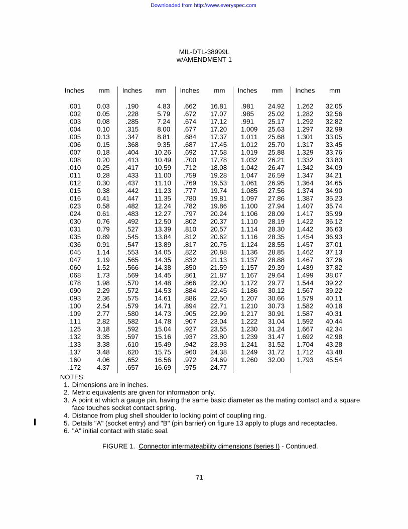
MIL-DTL-38999L w/AMENDMENT 1
71
Inches mm Inches mm Inches mm Inches mm Inches mm
.001 .002 .003 .004 .005 .006 .007 .008 .010 .011 .012 .015 .016 .023 .024 .030 .031 .035 .036 .045 .047 .060 .068 .078 .090 .093 .100 .109 .111 .125 .132 .133 .137 .160 .172
0.03 0.05 0.08 0.10 0.13 0.15 0.18 0.20 0.25 0.28 0.30 0.38 0.41 0.58 0.61 0.76 0.79 0.89 0.91 1.14 1.19 1.52 1.73 1.98 2.29 2.36 2.54 2.77 2.82 3.18 3.35 3.38 3.48 4.06 4.37
.190 .228 .285 .315 .347 .368 .404 .413 .417 .433 .437 .442 .447 .482 .483 .492 .527 .545 .547 .553 .565 .566 .569 .570 .572 .575 .579 .580 .582 .592 .597 .610 .620 .652 .657
4.83 5.79 7.24 8.00 8.81 9.35 10.26 10.49 10.59 11.00 11.10 11.23 11.35 12.24 12.27 12.50 13.39 13.84 13.89 14.05 14.35 14.38 14.45 14.48 14.53 14.61 14.71 14.73 14.78 15.04 15.16 15.49 15.75 16.56 16.69
.662 .672 .674 .677 .684 .687 .692 .700 .712 .759 .769 .777 .780 .782 .797 .802 .810 .812 .817 .822 .832 .850 .861 .866 .884 .886 .894 .905 .907 .927 .937 .942 .960 .972 .975
16.81 17.07 17.12 17.20 17.37 17.45 17.58 17.78 18.08 19.28 19.53 19.74 19.81 19.86 20.24 20.37 20.57 20.62 20.75 20.88 21.13 21.59 21.87 22.00 22.45 22.50 22.71 22.99 23.04 23.55 23.80 23.93 24.38 24.69 24.77
.981 .985 .991
1.009 1.011 1.012 1.019 1.032 1.042 1.047 1.061 1.085 1.097 1.100 1.106 1.110 1.114 1.116 1.124 1.136 1.137 1.157 1.167 1.172 1.186 1.207 1.210 1.217 1.222 1.230 1.239 1.241 1.249 1.260
24.92 25.02 25.17 25.63 25.68 25.70 25.88 26.21 26.47 26.59 26.95 27.56 27.86 27.94 28.09 28.19 28.30 28.35 28.55 28.85 28.88 29.39 29.64 29.77 30.12 30.66 30.73 30.91 31.04 31.24 31.47 31.52 31.72 32.00
1.262 1.282 1.292 1.297 1.301 1.317 1.329 1.332 1.342 1.347 1.364 1.374 1.387 1.407 1.417 1.422 1.442 1.454 1.457 1.462 1.467 1.489 1.499 1.544 1.567 1.579 1.582 1.587 1.592 1.667 1.692 1.704 1.712 1.793
32.05 32.56 32.82 32.99 33.05 33.45 33.76 33.83 34.09 34.21 34.65 34.90 35.23 35.74 35.99 36.12 36.63 36.93 37.01 37.13 37.26 37.82 38.07 39.22 39.22 40.11 40.18 40.31 40.44 42.34 42.98 43.28 43.48 45.54
NOTES: 1. Dimensions are in inches. 2. Metric equivalents are given for information only. 3. A point at which a gauge pin, having the same basic diameter as the mating contact and a square
face touches socket contact spring. 4. Distance from plug shell shoulder to locking point of coupling ring. 5. Details "A" (socket entry) and "B" (pin barrier) on figure 13 apply to plugs and receptacles. 6. "A" initial contact with static seal.
FIGURE 1. Connector intermateability dimensions (series I) - Continued.
Downloaded from http://www.everyspec.com
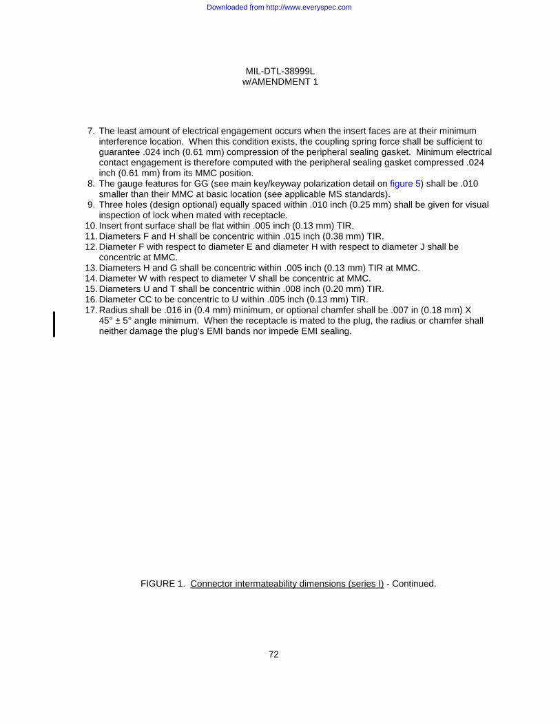
MIL-DTL-38999L w/AMENDMENT 1
72
7. The least amount of electrical engagement occurs when the insert faces are at their minimum
interference location. When this condition exists, the coupling spring force shall be sufficient to guarantee .024 inch (0.61 mm) compression of the peripheral sealing gasket. Minimum electrical contact engagement is therefore computed with the peripheral sealing gasket compressed .024 inch (0.61 mm) from its MMC position.
8. The gauge features for GG (see main key/keyway polarization detail on figure 5) shall be .010 smaller than their MMC at basic location (see applicable MS standards).
9. Three holes (design optional) equally spaced within .010 inch (0.25 mm) shall be given for visual inspection of lock when mated with receptacle.
10. Insert front surface shall be flat within .005 inch (0.13 mm) TIR. 11. Diameters F and H shall be concentric within .015 inch (0.38 mm) TIR. 12. Diameter F with respect to diameter E and diameter H with respect to diameter J shall be
concentric at MMC. 13. Diameters H and G shall be concentric within .005 inch (0.13 mm) TIR at MMC. 14. Diameter W with respect to diameter V shall be concentric at MMC. 15. Diameters U and T shall be concentric within .008 inch (0.20 mm) TIR. 16. Diameter CC to be concentric to U within .005 inch (0.13 mm) TIR. 17. Radius shall be .016 in (0.4 mm) minimum, or optional chamfer shall be .007 in (0.18 mm) X 45° ± 5° angle minimum. When the receptacle is mated to the plug, the radius or chamfer shall
neither damage the plug's EMI bands nor impede EMI sealing.
FIGURE 1. Connector intermateability dimensions (series I) - Continued.
Downloaded from http://www.everyspec.com
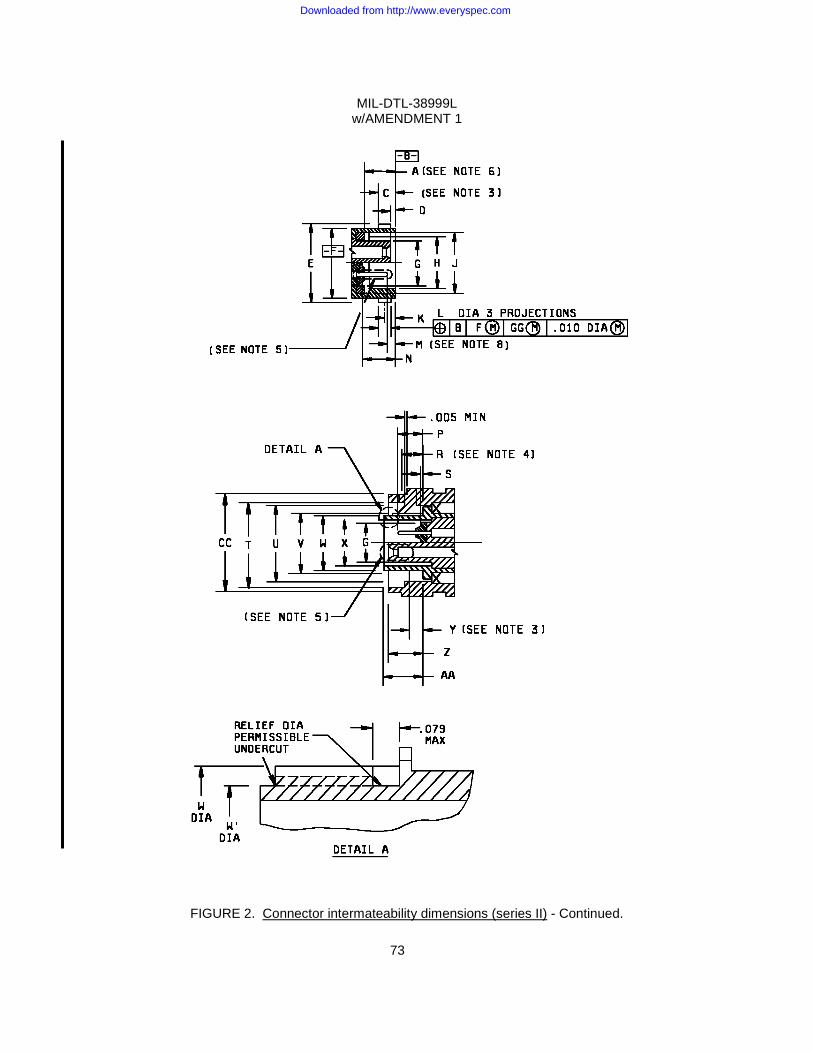
MIL-DTL-38999L w/AMENDMENT 1
73
FIGURE 2. Connector intermateability dimensions (series II) - Continued.
Downloaded from http://www.everyspec.com

MIL-DTL-38999L w/AMENDMENT 1
74
Shell size
A gasket location
C (see note 3)
D socket insert
location
E dia
+.000 -.016
F dia
+.001 -.005
G dia
+.005 -.010
H dia
+.005 -.001
8
.232
.216
.111 max
.023
.015
.563 .473 .285 .362
10 .680 .590 .413 .490
12 .859 .750 .527 .607
14 .984 .875 .652 .732
16 1.108 1.000 .777 .857
18 1.233 1.125 .866 .962
20 1.358 1.250 .991 1.087
22 1.483 1.375 1.116 1.212
24 1.610 1.500 1.241 1.337
FIGURE 2. Connector intermateability dimensions (series II) - Continued.
Downloaded from http://www.everyspec.com
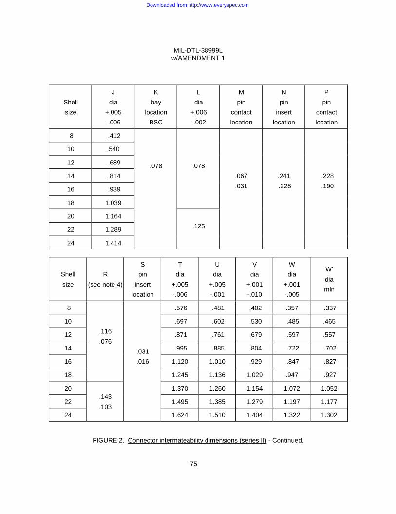
MIL-DTL-38999L w/AMENDMENT 1
75
Shell size
J dia
+.005 -.006
K bay
location BSC
L dia
+.006 -.002
M pin
contact location
N pin
insert location
P pin
contact location
8 .412
.078
.078
.067
.031
.241 .228
.228 .190
10 .540
12 .689
14 .814
16 .939
18 1.039
20 1.164 .125 22 1.289
24 1.414
Shell size
R (see note 4)
S pin
insert location
T dia
+.005 -.006
U dia
+.005 -.001
V dia
+.001 -.010
W dia
+.001 -.005
W' dia min
8
.116
.076 .031
.016
.576 .481 .402 .357 .337
10 .697 .602 .530 .485 .465
12 .871 .761 .679 .597 .557
14 .995 .885 .804 .722 .702
16 1.120 1.010 .929 .847 .827
18 1.245 1.136 1.029 .947 .927
20 .143 .103
1.370 1.260 1.154 1.072 1.052
22 1.495 1.385 1.279 1.197 1.177
24 1.624 1.510 1.404 1.322 1.302
FIGURE 2. Connector intermateability dimensions (series II) - Continued.
Downloaded from http://www.everyspec.com
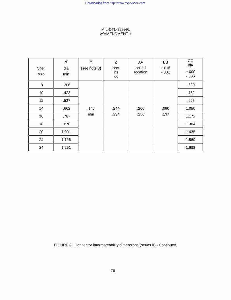
MIL-DTL-38999L w/AMENDMENT 1
76
Shell size
X dia min
Y (see note 3)
Z soc ins loc
AA shield
location
BB +.015 -.001
CC dia
+.000 -.006
8 .306
.146 min
.244
.234
.260
.256
.090
.137
.630
10 .423 .752
12 .537 .925
14 .662 1.050
16 .787 1.172
18 .876 1.304
20 1.001 1.435
22 1.126 1.560
24 1.251 1.688
FIGURE 2. Connector intermateability dimensions (series II) - Continued.
Downloaded from http://www.everyspec.com
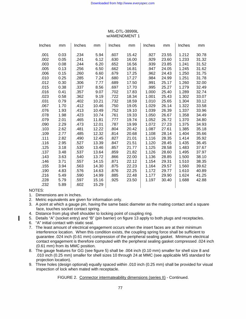
MIL-DTL-38999L w/AMENDMENT 1
77
Inches mm Inches mm Inches mm Inches mm Inches mm
.001
.002
.003
.005
.006
.010
.012
.015
.016
.023
.031
.067
.076
.078
.079
.090
.103
.109
.111
.116
.125
.137
.143
.146
.155
.190
.216
.228
.232
0.03 0.05 0.08 0.13 0.15 0.25 0.30 0.38 0.41 0.58 0.79 1.70 1.93 1.98 2.01 2.29 2.62 2.77 2.82 2.95 3.18 3.48 3.63 3.71 3.94 4.83 5.49 5.79 5.89
.234 .241 .244 .256 .260 .285 .306 .337 .357 .362 .402 .412 .413 .423 .465 .473 .481 .485 .490 .527 .530 .537 .540 .557 .563 .576 .590 .597 .602
5.94 6.12 6.20 6.50 6.60 7.24 7.77 8.56 9.07 9.19
10.21 10.46 10.49 10.74 11.81 12.01 12.22 12.32 12.45 13.39 13.46 13.64 13.72 14.15 14.30 14.63 14.99 15.16 15.29
.607 .630 .652 .662 .679 .680 .689 .697 .702 .722 .732 .750 .752 .761 .777 .787 .804 .814 .827 .847 .857 .859 .866 .871 .875 .876 .885 .925
15.42 16.00 16.56 16.81 17.25 17.27 17.50 17.70 17.83 18.34 18.59 19.05 19.10 19.33 19.74 19.99 20.42 20.68 21.01 21.51 21.77 21.82 22.00 22.12 22.23 22.25 22.48 23.50
.927 .929 .939 .947 .962 .984 .991 .995
1.000 1.001 1.010 1.029 1.039 1.050 1.052 1.072 1.087 1.108 1.116 1.120 1.125 1.126 1.136 1.154 1.164 1.172 1.177 1.197
23.55 23.60 23.85 24.05 24.43 24.99 25.17 25.27 25.40 25.43 25.65 26.14 26.39 26.67 26.72 27.23 27.61 28.14 28.35 28.45 28.58 28.60 28.85 29.31 29.57 29.77 29.90 30.40
1.212 1.233 1.241 1.245 1.250 1.251 1.260 1.279 1.289 1.302 1.304 1.322 1.337 1.358 1.370 1.375 1.385 1.404 1.414 1.435 1.483 1.495 1.500 1.510 1.560 1.610 1.624 1.688
30.78 31.32 31.52 31.62 31.75 31.78 32.00 32.49 32.74 33.07 33.12 33.58 33.96 34.49 34.80 34.93 35.18 35.66 35.92 36.45 37.67 37.97 38.10 38.35 39.62 40.89 41.25 42.88
NOTES: 1. Dimensions are in inches. 2. Metric equivalents are given for information only. 3. A point at which a gauge pin, having the same basic diameter as the mating contact and a square
face, touches socket contact spring. 4. Distance from plug shell shoulder to locking point of coupling ring. 5. Details “A” (socket entry) and “B” (pin barrier) on figure 13 apply to both plugs and receptacles. 6. “A” initial contact with static seal. 7. The least amount of electrical engagement occurs when the insert faces are at their minimum
interference location. When this condition exists, the coupling spring force shall be sufficient to guarantee .024 inch (0.61 mm) compression of the peripheral sealing gasket. Minimum electrical contact engagement is therefore computed with the peripheral sealing gasket compressed .024 inch (0.61 mm) from its MMC position.
8. The gauge features for GG (see figure 5) shall be .004 inch (0.10 mm) smaller for shell size 8 and .010 inch (0.25 mm) smaller for shell sizes 10 through 24 at MMC (see applicable MS standard for projection location).
9. Three holes (design optional) equally spaced within .010 inch (0.25 mm) shall be provided for visual inspection of lock when mated with receptacle.
FIGURE 2. Connector intermateability dimensions (series II) - Continued.
Downloaded from http://www.everyspec.com
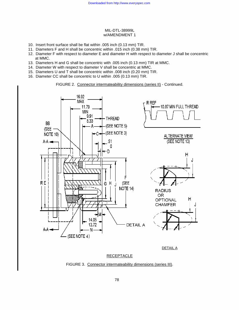
MIL-DTL-38999L w/AMENDMENT 1
78
10. Insert front surface shall be flat within .005 inch (0.13 mm) TIR. 11. Diameters F and H shall be concentric within .015 inch (0.38 mm) TIR. 12. Diameter F with respect to diameter E and diameter H with respect to diameter J shall be concentric
at MMC. 13. Diameters H and G shall be concentric with .005 inch (0.13 mm) TIR at MMC. 14. Diameter W with respect to diameter V shall be concentric at MMC. 15. Diameters U and T shall be concentric within .008 inch (0.20 mm) TIR. 16. Diameter CC shall be concentric to U within .005 (0.13 mm) TIR.
FIGURE 2. Connector intermateability dimensions (series II) - Continued.
DETAIL A
RECEPTACLE
FIGURE 3. Connector intermateability dimensions (series III).
Downloaded from http://www.everyspec.com
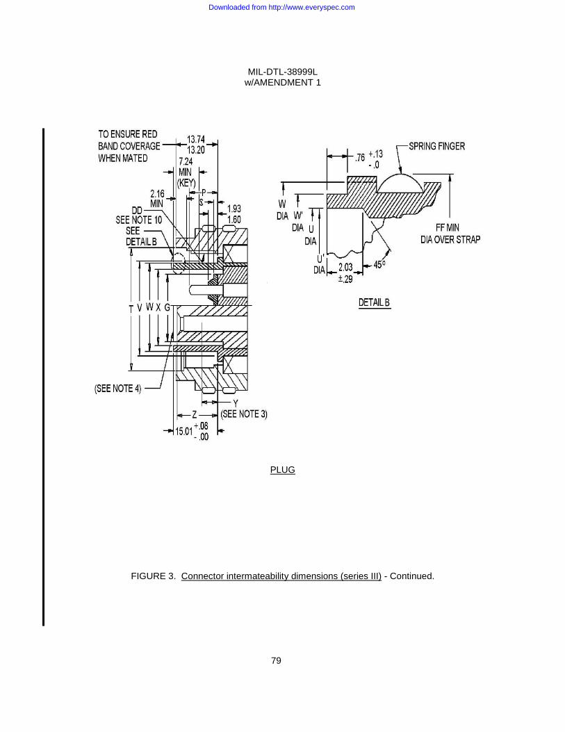
MIL-DTL-38999L w/AMENDMENT 1
79
PLUG
FIGURE 3. Connector intermateability dimensions (series III) - Continued.
Downloaded from http://www.everyspec.com
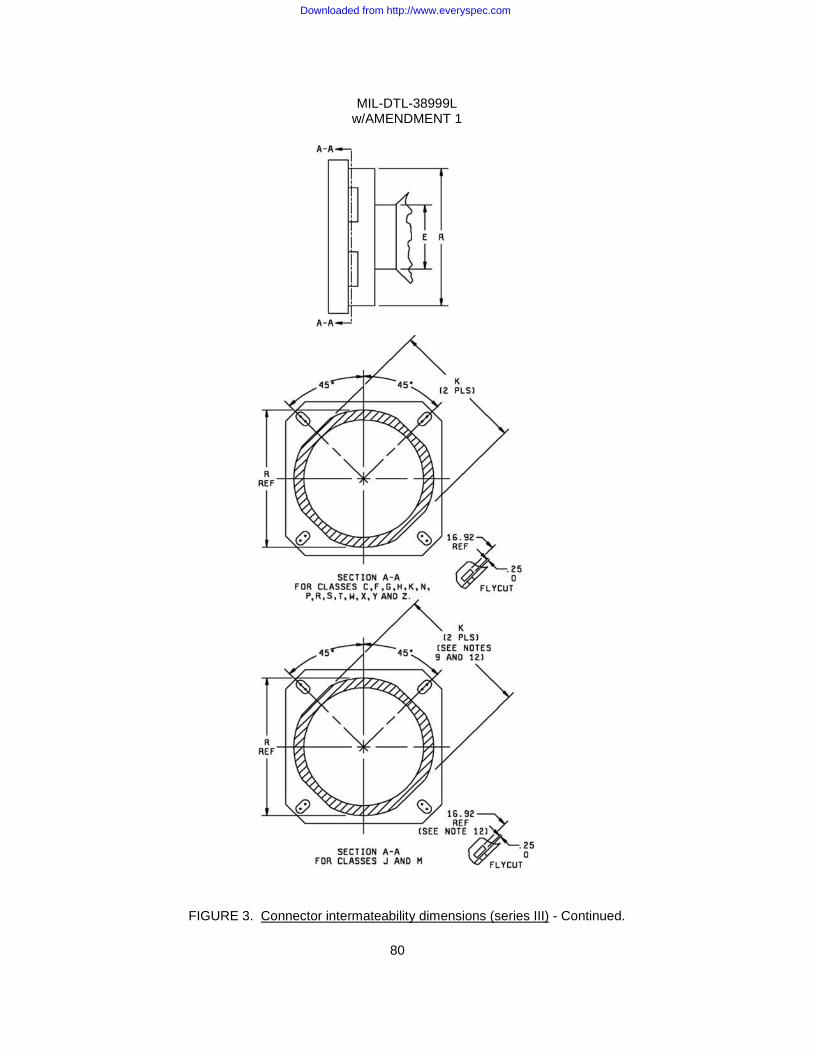
MIL-DTL-38999L w/AMENDMENT 1
80
FIGURE 3. Connector intermateability dimensions (series III) - Continued.
Downloaded from http://www.everyspec.com
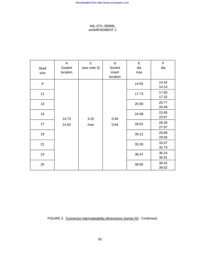
MIL-DTL-38999L w/AMENDMENT 1
81
Shell size
A Gasket location
C (see note 3)
D Socket insert
location
E dia max
F dia
9
14.73
14.50
3.25
max
0.94
0.64
14.55 14.42 14.14
11 17.73 17.60 17.32
13 20.90 20.77 20.49
15 24.08 23.95 23.67
17 28.52 28.30 27.97
19 30.12 29.89 29.56
21 33.30 33.07 32.74
23 36.47 36.24 35.91
25 39.65 39.42 39.02
FIGURE 3. Connector intermateability dimensions (series III) - Continued.
Downloaded from http://www.everyspec.com
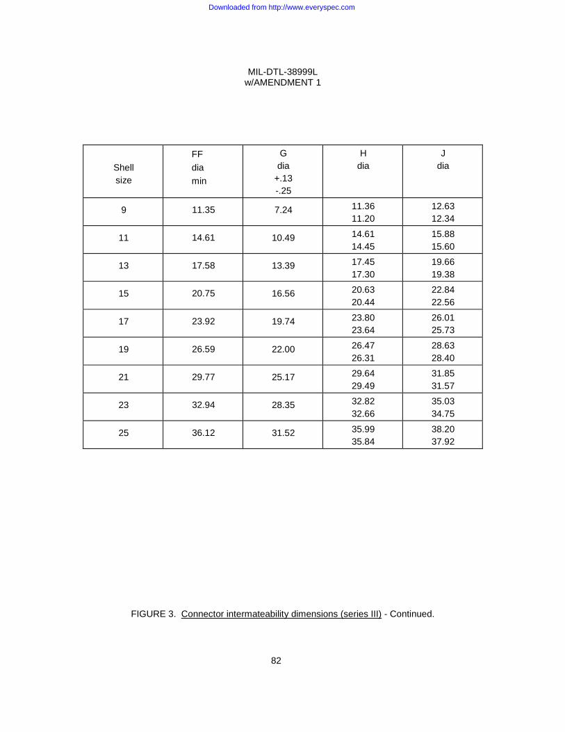
MIL-DTL-38999L w/AMENDMENT 1
82
Shell size
FF dia min
G dia
+.13 -.25
H dia
J dia
9 11.35 7.24 11.36 11.20
12.63 12.34
11 14.61 10.49 14.61 14.45
15.88 15.60
13 17.58 13.39 17.45 17.30
19.66 19.38
15 20.75 16.56 20.63 20.44
22.84 22.56
17 23.92 19.74 23.80 23.64
26.01 25.73
19 26.59 22.00 26.47 26.31
28.63 28.40
21 29.77 25.17 29.64 29.49
31.85 31.57
23 32.94 28.35 32.82 32.66
35.03 34.75
25 36.12 31.52 35.99 35.84
38.20 37.92
FIGURE 3. Connector intermateability dimensions (series III) - Continued.
Downloaded from http://www.everyspec.com
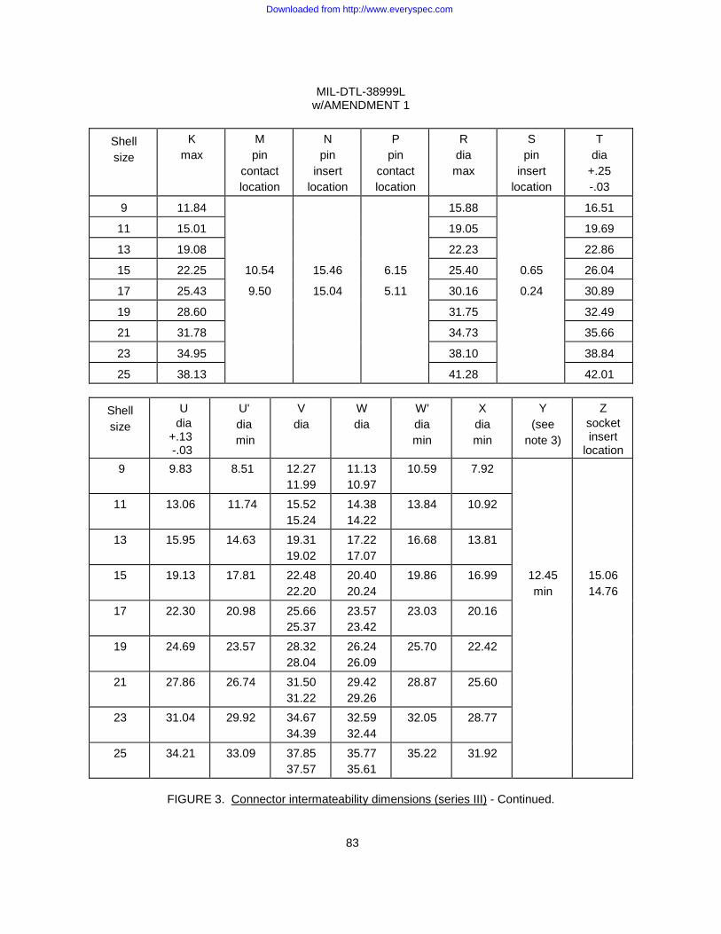
MIL-DTL-38999L w/AMENDMENT 1
83
Shell size
K max
M pin
contact location
N pin
insert location
P pin
contact location
R dia max
S pin
insert location
T dia
+.25 -.03
9 11.84 15.88 16.51
11 15.01 19.05 19.69
13 19.08 22.23 22.86
15 22.25 10.54 15.46 6.15 25.40 0.65 26.04
17 25.43 9.50 15.04 5.11 30.16 0.24 30.89
19 28.60 31.75 32.49
21 31.78 34.73 35.66
23 34.95 38.10 38.84
25 38.13 41.28 42.01
Shell size
U dia +.13 -.03
U' dia min
V dia
W dia
W' dia min
X dia min
Y (see
note 3)
Z socket insert
location 9 9.83 8.51 12.27
11.99 11.13 10.97
10.59 7.92
11 13.06 11.74 15.52 15.24
14.38 14.22
13.84 10.92
13 15.95 14.63 19.31 19.02
17.22 17.07
16.68 13.81
15 19.13 17.81 22.48 22.20
20.40 20.24
19.86 16.99 12.45 min
15.06 14.76
17 22.30 20.98 25.66 25.37
23.57 23.42
23.03 20.16
19 24.69 23.57 28.32 28.04
26.24 26.09
25.70 22.42
21 27.86 26.74 31.50 31.22
29.42 29.26
28.87 25.60
23 31.04 29.92 34.67 34.39
32.59 32.44
32.05 28.77
25 34.21 33.09 37.85 37.57
35.77 35.61
35.22 31.92
FIGURE 3. Connector intermateability dimensions (series III) - Continued.
Downloaded from http://www.everyspec.com
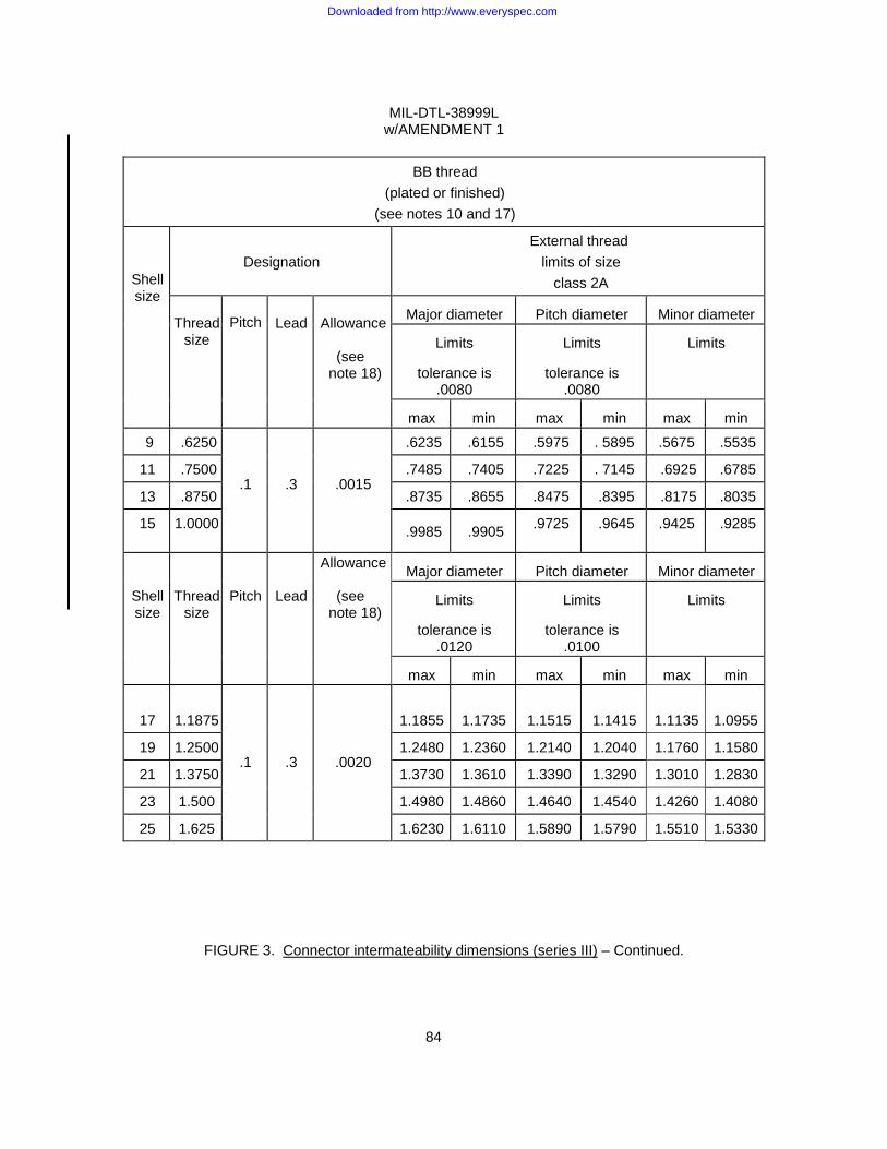
MIL-DTL-38999L w/AMENDMENT 1
84
BB thread
(plated or finished) (see notes 10 and 17)
Shell size
Designation
External thread limits of size
class 2A Thread
size
Pitch
Lead
Allowance
(see
note 18)
Major diameter
Pitch diameter
Minor diameter
Limits
tolerance is
.0080
Limits
tolerance is
.0080
Limits
max
min
max
min
max
min
9 .6250
.1
.3
.0015
.6235 .6155 .5975 . 5895 .5675 .5535
11 .7500 .7485 .7405 .7225 . 7145 .6925 .6785
13 .8750 .8735 .8655 .8475 .8395 .8175 .8035
15 1.0000 .9985 .9905 .9725 .9645 .9425 .9285
Shell size
Thread size
Pitch
Lead
Allowance
(see note 18)
Major diameter
Pitch diameter
Minor diameter
Limits
tolerance is
.0120
Limits
tolerance is
.0100
Limits
max
min
max
min
max
min
17
1.1875
.1
.3
.0020
1.1855
1.1735
1.1515
1.1415
1.1135
1.0955
19 1.2500 1.2480 1.2360 1.2140 1.2040 1.1760 1.1580
21 1.3750 1.3730 1.3610 1.3390 1.3290 1.3010 1.2830
23 1.500 1.4980 1.4860 1.4640 1.4540 1.4260 1.4080
25 1.625 1.6230 1.6110 1.5890 1.5790 1.5510 1.5330
FIGURE 3. Connector intermateability dimensions (series III) – Continued.
Downloaded from http://www.everyspec.com

MIL-DTL-38999L w/AMENDMENT 1
85
DD thread
(plated) (see notes 10 and 17)
Shell size
Designation
Internal thread limits of size
class 2B Thread
size
Pitch
Lead
Minor diameter
Pitch diameter
Major diameter
Limits
tolerance is
.0100
Limits
tolerance is
.0100
Limits
min
max
min
max
min
max
9
.6250
.1
.3
.5792
.5892
.5990
.6090
.6290
.6450
11
.7500
.7042
.7142
.7240
.7340
.7540
.7700
13
.8750
.8292
.8392
.8490
.8590
.8790
.8950
15
1.0000
.9542
.9642
.9740
.9840
1.0040
1.0200
Shell size
Thread size
Pitch
Lead
Minor diameter
Pitch diameter
Major diameter
Limits
tolerance is
.0120
Limits
tolerance is
.0120
Limits
min
max
min
max
min
max
17
1.1875
.1
.3
1.1274
1.1394
1.1535
1.1655
1.1915
1.2115
19
1.2500
1.1900 1.2020
1.2160
1.2280
1.2540
1.2740
21
1.3750
1.3150 1.3270
1.3410
1.3530
1.3790
1.3990
23
1.5000
1.4400 1.4520
1.4660
1.4780
1.5040
1.5240
25
1.6250
1.5650 1.5770
1.5910
1.6030
1.6290
1.6490
FIGURE 3. Connector intermateability dimensions (series III) – Continued.
Downloaded from http://www.everyspec.com
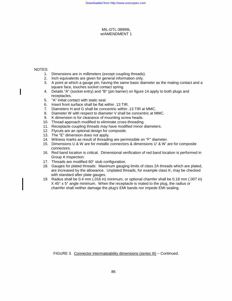
MIL-DTL-38999L w/AMENDMENT 1
86
NOTES: 1. Dimensions are in millimeters (except coupling threads). 2. Inch equivalents are given for general information only.
3. A point at which a gauge pin, having the same basic diameter as the mating contact and a square face, touches socket contact spring.
4. Details "A" (socket entry) and "B" (pin barrier) on figure 14 apply to both plugs and receptacles.
5. "A" initial contact with static seal. 6. Insert front surface shall be flat within .13 TIR. 7. Diameters H and G shall be concentric within .13 TIR at MMC. 8. Diameter W with respect to diameter V shall be concentric at MMC. 9. K dimension is for clearance of mounting screw heads. 10. Thread approach modified to eliminate cross-threading. 11. Receptacle coupling threads may have modified minor diameters. 12. Flycuts are an optional design for composite. 13. The "E" dimension does not apply. 14. Witness marks as result of threading are permissible on "F" diameter.
15. Dimensions U & W are for metallic connectors & dimensions U' & W' are for composite connectors.
16. Red band location is critical. Dimensional verification of red band location is performed in Group A Inspection.
17. Threads are modified 60° stub configuration. 18. Gauges for plated threads: Maximum gauging limits of class 2A threads which are plated,
are increased by the allowance. Unplated threads, for example class K, may be checked with standard after plate gauges.
19. Radius shall be 0.4 mm (.016 in) minimum, or optional chamfer shall be 0.18 mm (.007 in) X 45° ± 5° angle minimum. When the receptacle is mated to the plug, the radius or chamfer shall neither damage the plug's EMI bands nor impede EMI sealing.
FIGURE 3. Connector intermateability dimensions (series III) – Continued.
Downloaded from http://www.everyspec.com
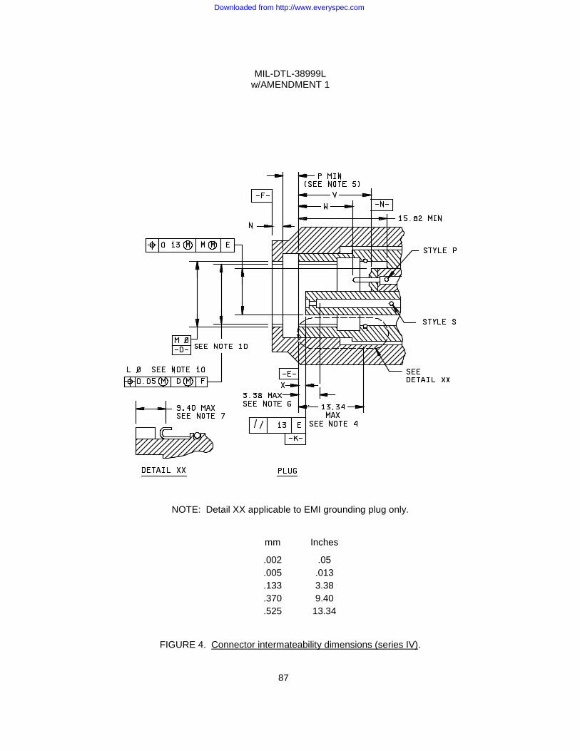
MIL-DTL-38999L w/AMENDMENT 1
87
NOTE: Detail XX applicable to EMI grounding plug only.
mm Inches
.002 .05
.005 .013
.133 3.38
.370 9.40
.525 13.34
FIGURE 4. Connector intermateability dimensions (series IV).
Downloaded from http://www.everyspec.com
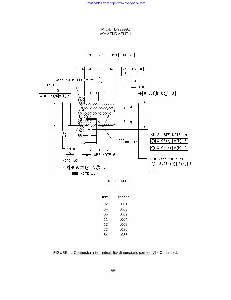
MIL-DTL-38999L w/AMENDMENT 1
88
mm Inches
.02 .001
.04 .002
.05 .002
.11 .004
.13 .005
.73 .029
.84 .033
FIGURE 4. Connector intermateability dimensions (series IV) - Continued.
Downloaded from http://www.everyspec.com
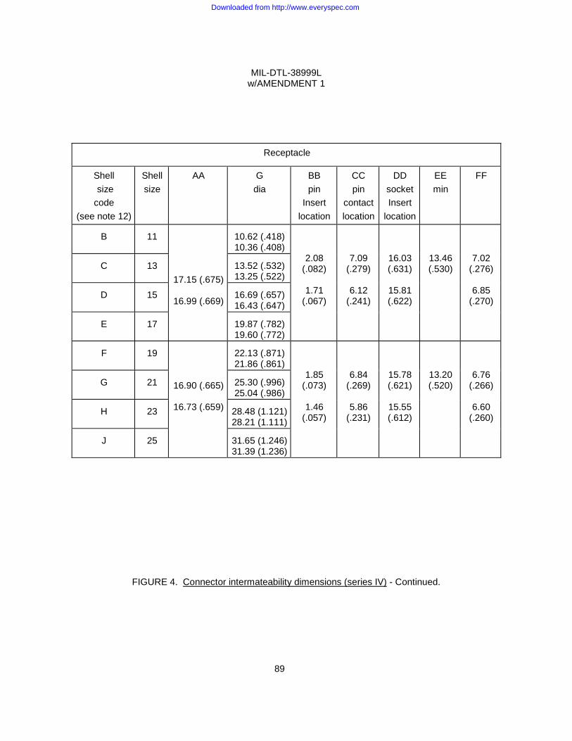
MIL-DTL-38999L w/AMENDMENT 1
89
Receptacle
Shell size code
(see note 12)
Shell size
AA
G dia
BB pin
Insert location
CC pin
contact location
DD socket Insert
location
EE min
FF
B
11
17.15 (.675)
16.99 (.669)
10.62 (.418) 10.36 (.408)
2.08 (.082)
1.71
(.067)
7.09 (.279)
6.12
(.241)
16.03 (.631)
15.81 (.622)
13.46 (.530)
7.02 (.276)
6.85
(.270)
C
13
13.52 (.532) 13.25 (.522)
D
15
16.69 (.657) 16.43 (.647)
E
17
19.87 (.782) 19.60 (.772)
F
19
16.90 (.665)
16.73 (.659)
22.13 (.871) 21.86 (.861)
1.85 (.073)
1.46
(.057)
6.84 (.269)
5.86
(.231)
15.78 (.621)
15.55 (.612)
13.20 (.520)
6.76 (.266)
6.60
(.260)
G
21
25.30 (.996) 25.04 (.986)
H
23
28.48 (1.121) 28.21 (1.111)
J
25
31.65 (1.246) 31.39 (1.236)
FIGURE 4. Connector intermateability dimensions (series IV) - Continued.
Downloaded from http://www.everyspec.com
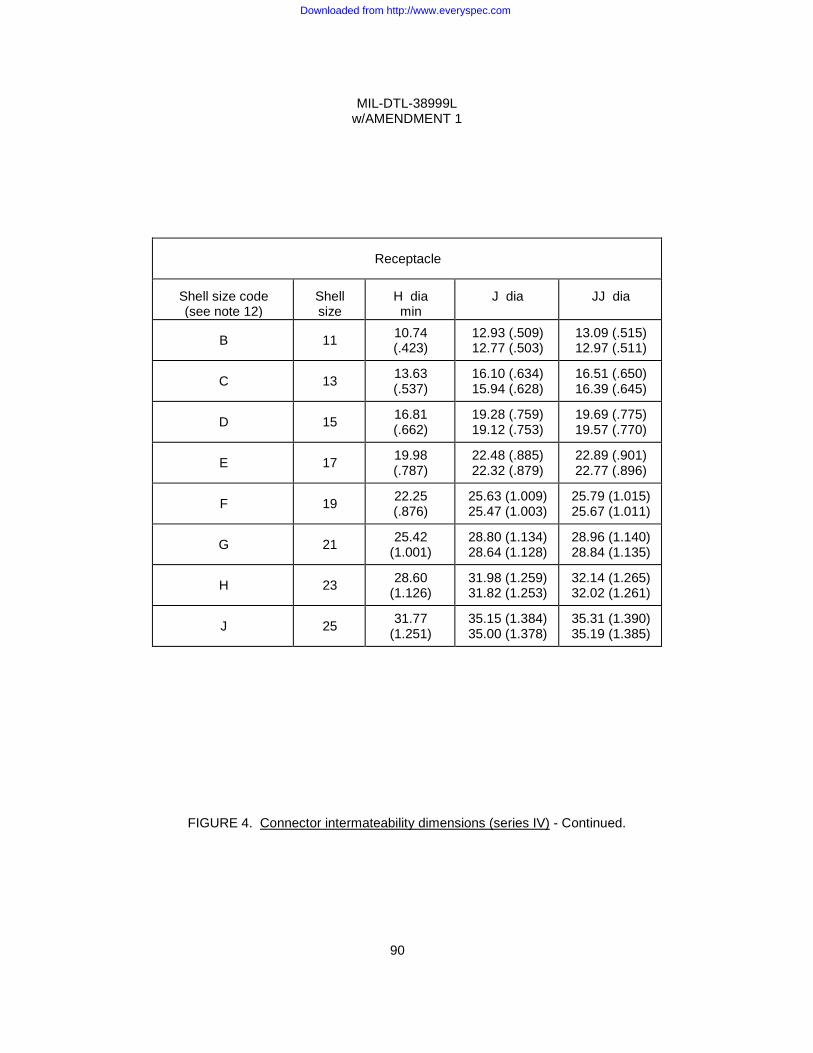
MIL-DTL-38999L w/AMENDMENT 1
90
Receptacle
Shell size code (see note 12)
Shell size
H dia min
J dia
JJ dia
B 11 10.74
(.423) 12.93 (.509) 12.77 (.503)
13.09 (.515) 12.97 (.511)
C 13 13.63 (.537)
16.10 (.634) 15.94 (.628)
16.51 (.650) 16.39 (.645)
D 15 16.81 (.662)
19.28 (.759) 19.12 (.753)
19.69 (.775) 19.57 (.770)
E 17 19.98 (.787)
22.48 (.885) 22.32 (.879)
22.89 (.901) 22.77 (.896)
F 19 22.25 (.876)
25.63 (1.009) 25.47 (1.003)
25.79 (1.015) 25.67 (1.011)
G 21 25.42 (1.001)
28.80 (1.134) 28.64 (1.128)
28.96 (1.140) 28.84 (1.135)
H 23 28.60 (1.126)
31.98 (1.259) 31.82 (1.253)
32.14 (1.265) 32.02 (1.261)
J 25 31.77 (1.251)
35.15 (1.384) 35.00 (1.378)
35.31 (1.390) 35.19 (1.385)
FIGURE 4. Connector intermateability dimensions (series IV) - Continued.
Downloaded from http://www.everyspec.com
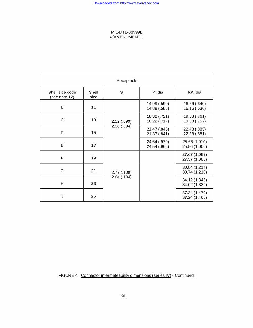
MIL-DTL-38999L w/AMENDMENT 1
91
Receptacle
Shell size code (see note 12)
Shell size
S
K dia
KK dia
B
11
2.52 (.099) 2.38 (.094)
14.99 (.590) 14.89 (.586)
16.26 (.640) 16.16 (.636)
C
13
18.32 (.721) 18.22 (.717)
19.33 (.761) 19.23 (.757)
D
15
21.47 (.845) 21.37 (.841)
22.48 (.885) 22.38 (.881)
E
17
24.64 (.970) 24.54 (.966)
25.66 1.010) 25.56 (1.006)
F
19
2.77 (.109) 2.64 (.104)
27.67 (1.089) 27.57 (1.085)
G
21
30.84 (1.214) 30.74 (1.210)
H
23
34.12 (1.343) 34.02 (1.339)
J
25
37.34 (1.470) 37.24 (1.466)
FIGURE 4. Connector intermateability dimensions (series IV) - Continued.
Downloaded from http://www.everyspec.com
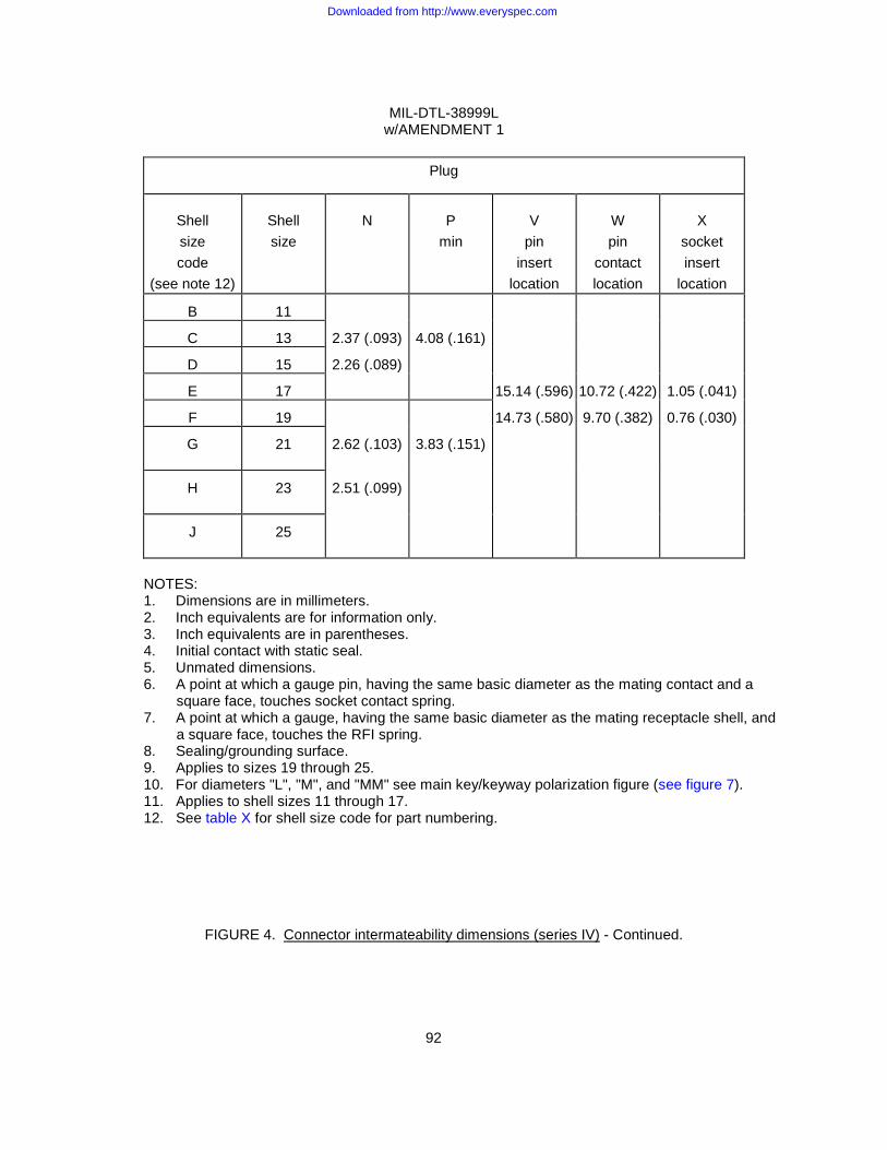
MIL-DTL-38999L w/AMENDMENT 1
92
Plug
Shell size code
(see note 12)
Shell size
N
P
min
V
pin insert
location
W pin
contact location
X
socket insert
location
B
11
C
13 2.37 (.093) 4.08 (.161)
D
15 2.26 (.089)
E
17 15.14 (.596) 10.72 (.422) 1.05 (.041)
F
19 14.73 (.580) 9.70 (.382) 0.76 (.030)
G
21 2.62 (.103) 3.83 (.151)
H
23 2.51 (.099)
J
25
NOTES: 1. Dimensions are in millimeters. 2. Inch equivalents are for information only. 3. Inch equivalents are in parentheses. 4. Initial contact with static seal. 5. Unmated dimensions. 6. A point at which a gauge pin, having the same basic diameter as the mating contact and a
square face, touches socket contact spring. 7. A point at which a gauge, having the same basic diameter as the mating receptacle shell, and
a square face, touches the RFI spring. 8. Sealing/grounding surface. 9. Applies to sizes 19 through 25. 10. For diameters "L", "M", and "MM" see main key/keyway polarization figure (see figure 7). 11. Applies to shell sizes 11 through 17. 12. See table X for shell size code for part numbering.
FIGURE 4. Connector intermateability dimensions (series IV) - Continued.
Downloaded from http://www.everyspec.com

MIL-DTL-38999L w/AMENDMENT 1
93
MAIN KEY/KEYWAY POLARIZATION
FIGURE 5. Connector intermateability dimensions. Main key / keyway polarization (series I and II).
mm Inches
.03 .001
.10 .004
.13 .005
.25 .010 1.32 .052 1.60 .063 2.54 .100 3.20 .126
Downloaded from http://www.everyspec.com
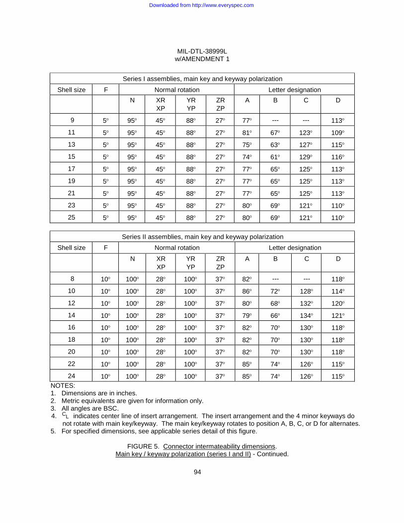
MIL-DTL-38999L w/AMENDMENT 1
94
Series I assemblies, main key and keyway polarization
Shell size F Normal rotation Letter designation N XR
XP YR YP
ZR ZP
A B C D
9 5° 95° 45° 88° 27° 77° --- --- 113°
11 5° 95° 45° 88° 27° 81° 67° 123° 109°
13 5° 95° 45° 88° 27° 75° 63° 127° 115°
15 5° 95° 45° 88° 27° 74° 61° 129° 116°
17 5° 95° 45° 88° 27° 77° 65° 125° 113°
19 5° 95° 45° 88° 27° 77° 65° 125° 113°
21 5° 95° 45° 88° 27° 77° 65° 125° 113°
23 5° 95° 45° 88° 27° 80° 69° 121° 110°
25 5° 95° 45° 88° 27° 80° 69° 121° 110°
Series II assemblies, main key and keyway polarization Shell size F Normal rotation Letter designation
N XR XP
YR YP
ZR ZP
A B C D
8 10° 100° 28° 100° 37° 82° --- --- 118°
10 10° 100° 28° 100° 37° 86° 72° 128° 114°
12 10° 100° 28° 100° 37° 80° 68° 132° 120°
14 10° 100° 28° 100° 37° 79° 66° 134° 121°
16 10° 100° 28° 100° 37° 82° 70° 130° 118°
18 10° 100° 28° 100° 37° 82° 70° 130° 118°
20 10° 100° 28° 100° 37° 82° 70° 130° 118°
22 10° 100° 28° 100° 37° 85° 74° 126° 115°
24 10° 100° 28° 100° 37° 85° 74° 126° 115° NOTES: 1. Dimensions are in inches. 2. Metric equivalents are given for information only. 3. All angles are BSC.
4. indicates center line of insert arrangement. The insert arrangement and the 4 minor keyways do not rotate with main key/keyway. The main key/keyway rotates to position A, B, C, or D for alternates.
5. For specified dimensions, see applicable series detail of this figure.
FIGURE 5. Connector intermateability dimensions. Main key / keyway polarization (series I and II) - Continued.
L C
Downloaded from http://www.everyspec.com
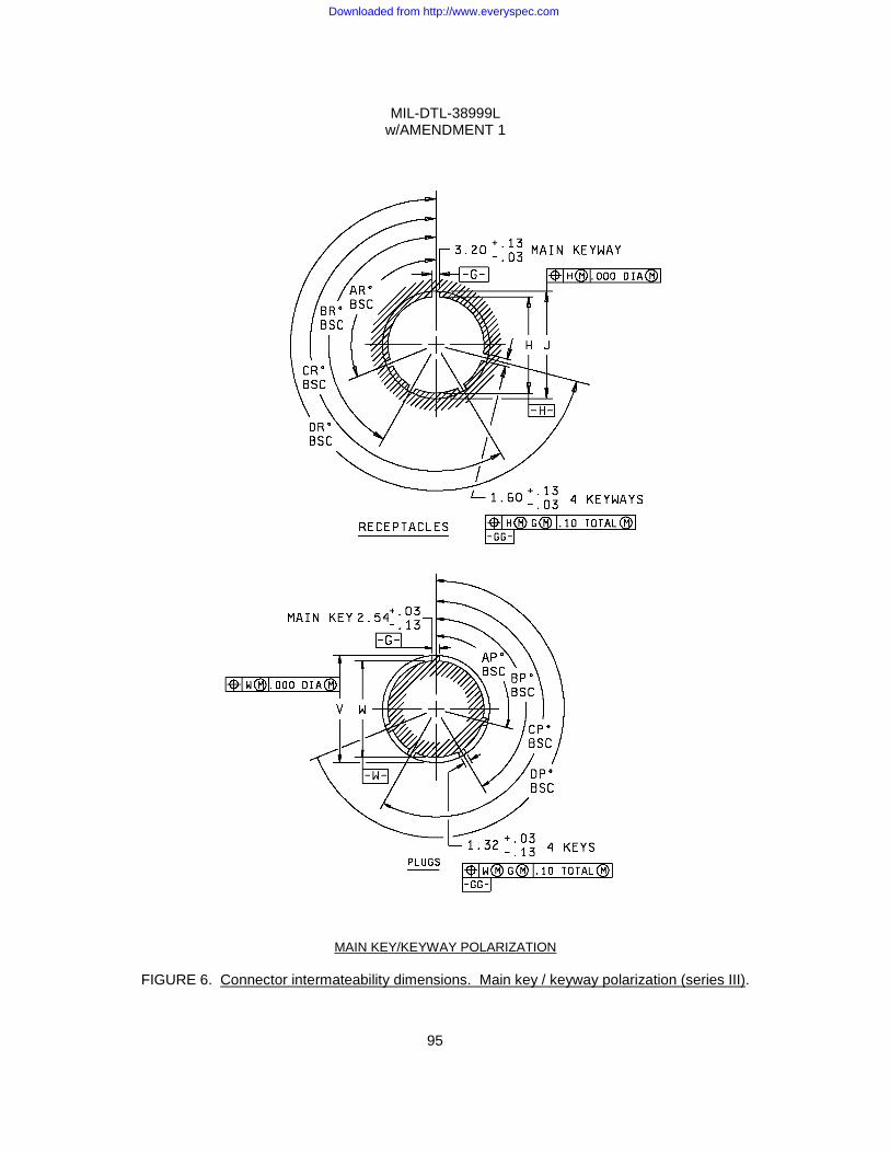
MIL-DTL-38999L w/AMENDMENT 1
95
MAIN KEY/KEYWAY POLARIZATION
FIGURE 6. Connector intermateability dimensions. Main key / keyway polarization (series III).
Downloaded from http://www.everyspec.com
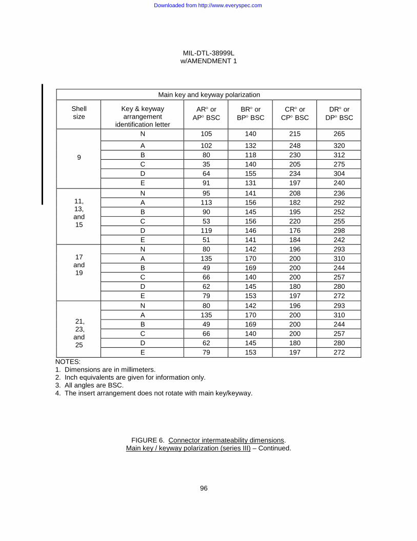
MIL-DTL-38999L w/AMENDMENT 1
96
Main key and keyway polarization
Shell size
Key & keyway arrangement
identification letter
AR° or
AP° BSC
BR° or
BP° BSC
CR° or
CP° BSC
DR° or
DP° BSC
9
N 105 140 215 265
A 102 132 248 320 B 80 118 230 312 C 35 140 205 275 D 64 155 234 304 E 91 131 197 240
11, 13, and 15
N 95 141 208 236 A 113 156 182 292 B 90 145 195 252 C 53 156 220 255 D 119 146 176 298 E 51 141 184 242
17
and 19
N 80 142 196 293 A 135 170 200 310 B 49 169 200 244 C 66 140 200 257 D 62 145 180 280 E 79 153 197 272
21, 23, and 25
N 80 142 196 293 A 135 170 200 310 B 49 169 200 244 C 66 140 200 257 D 62 145 180 280 E 79 153 197 272
NOTES: 1. Dimensions are in millimeters. 2. Inch equivalents are given for information only. 3. All angles are BSC. 4. The insert arrangement does not rotate with main key/keyway.
FIGURE 6. Connector intermateability dimensions.
Main key / keyway polarization (series III) – Continued.
Downloaded from http://www.everyspec.com
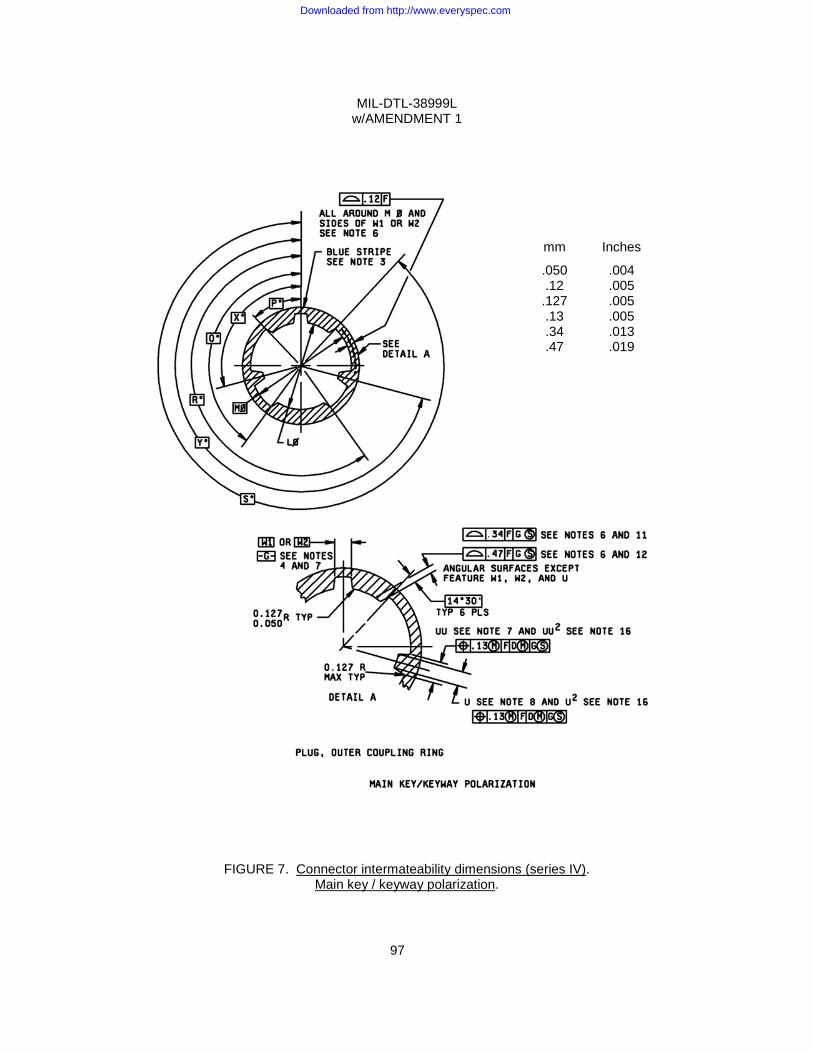
MIL-DTL-38999L w/AMENDMENT 1
97
FIGURE 7. Connector intermateability dimensions (series IV). Main key / keyway polarization.
mm Inches
.050 .004 .12 .005 .127 .005 .13 .005 .34 .013 .47 .019
Downloaded from http://www.everyspec.com
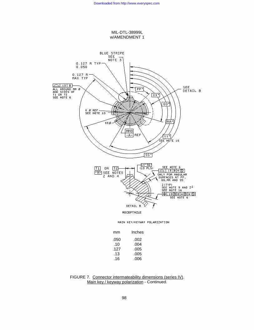
MIL-DTL-38999L w/AMENDMENT 1
98
FIGURE 7. Connector intermateability dimensions (series IV).
Main key / keyway polarization - Continued.
mm Inches
.050 .002 .10 .004 .127 .005 .13 .005 .16 .006
Downloaded from http://www.everyspec.com
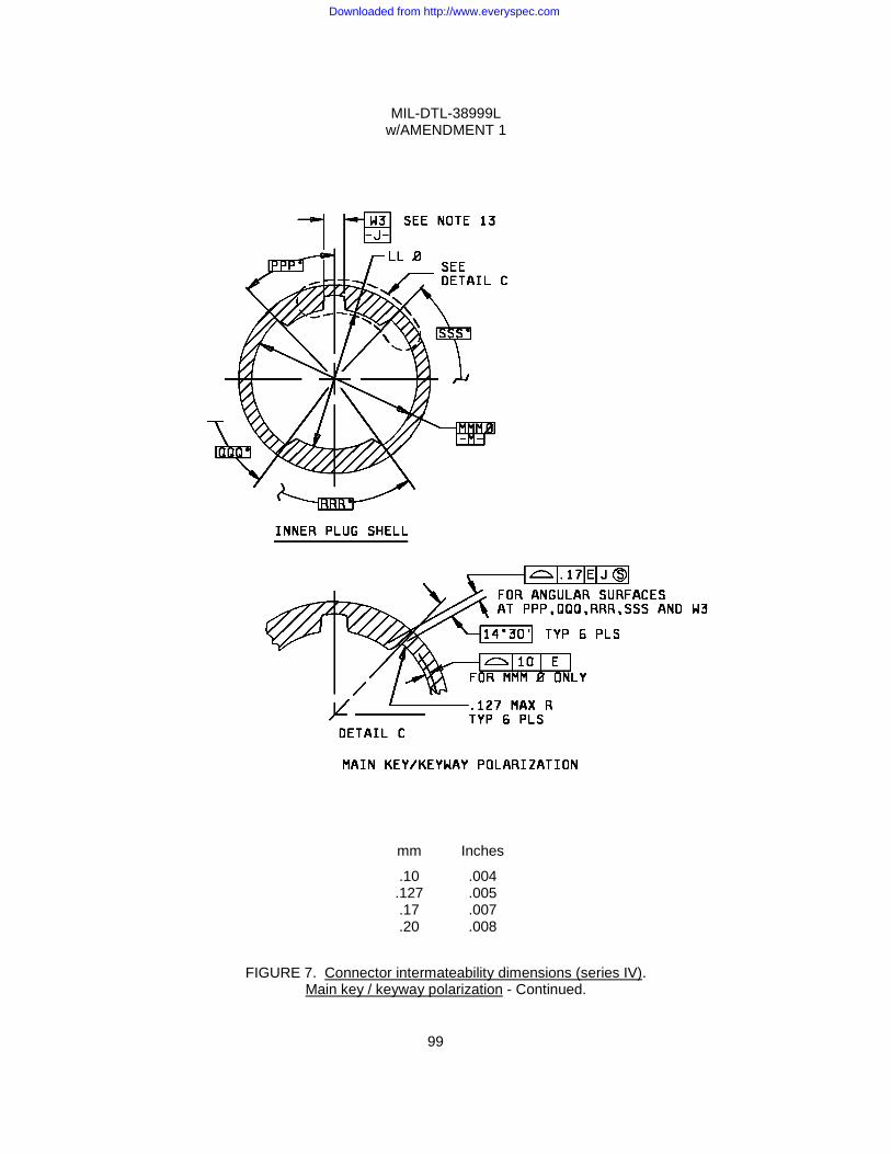
MIL-DTL-38999L w/AMENDMENT 1
99
FIGURE 7. Connector intermateability dimensions (series IV). Main key / keyway polarization - Continued.
mm Inches
.10 .004 .127 .005 .17 .007 .20 .008
Downloaded from http://www.everyspec.com
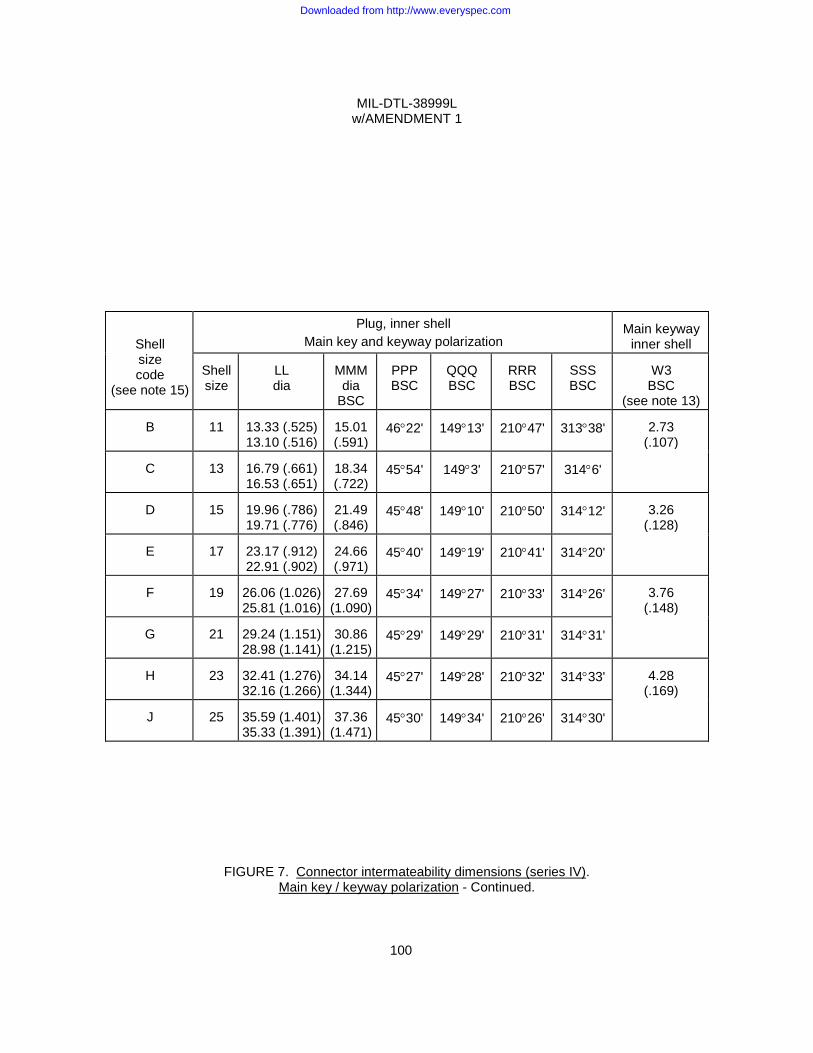
MIL-DTL-38999L w/AMENDMENT 1
100
Shell size code
(see note 15)
Plug, inner shell Main key and keyway polarization
Main keyway
inner shell Shell size
LL dia
MMM
dia BSC
PPP BSC
QQQ BSC
RRR BSC
SSS BSC
W3 BSC
(see note 13)
B
11 13.33 (.525) 13.10 (.516)
15.01 (.591)
46°22'
149°13'
210°47'
313°38'
2.73
(.107)
C
13 16.79 (.661) 16.53 (.651)
18.34 (.722)
45°54'
149°3'
210°57'
314°6'
D
15
19.96 (.786) 19.71 (.776)
21.49 (.846)
45°48'
149°10'
210°50'
314°12'
3.26
(.128)
E
17 23.17 (.912) 22.91 (.902)
24.66 (.971)
45°40'
149°19'
210°41'
314°20'
F
19
26.06 (1.026) 25.81 (1.016)
27.69
(1.090)
45°34'
149°27'
210°33'
314°26'
3.76
(.148)
G
21 29.24 (1.151) 28.98 (1.141)
30.86
(1.215)
45°29'
149°29'
210°31'
314°31'
H
23
32.41 (1.276) 32.16 (1.266)
34.14
(1.344)
45°27'
149°28'
210°32'
314°33'
4.28
(.169)
J
25 35.59 (1.401) 35.33 (1.391)
37.36
(1.471)
45°30'
149°34'
210°26'
314°30'
FIGURE 7. Connector intermateability dimensions (series IV). Main key / keyway polarization - Continued.
Downloaded from http://www.everyspec.com
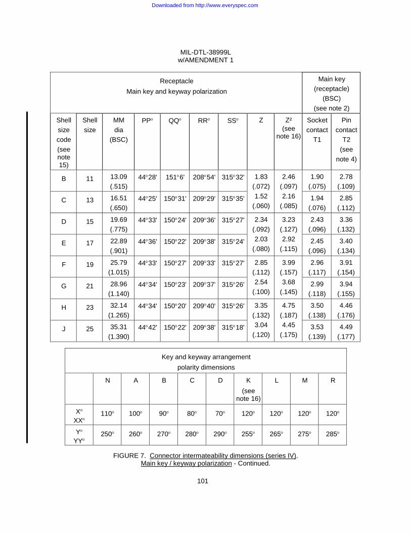
MIL-DTL-38999L w/AMENDMENT 1
101
Key and keyway arrangement polarity dimensions
N A B C D K (see
note 16)
L M R
X° XX°
110° 100° 90° 80° 70° 120° 120° 120° 120°
Y° YY°
250° 260° 270° 280° 290° 255° 265° 275° 285°
FIGURE 7. Connector intermateability dimensions (series IV).
Main key / keyway polarization - Continued.
Receptacle Main key and keyway polarization
Main key (receptacle)
(BSC) (see note 2)
Shell size code (see note 15)
Shell size
MM dia
(BSC)
PP°
QQ°
RR°
SS°
Z
Z² (see
note 16)
Socket contact
T1
Pin contact
T2 (see
note 4)
B 11 13.09 (.515)
44°28' 151°6' 208°54' 315°32' 1.83 (.072) 1.52
(.060)
2.46 (.097) 2.16
(.085)
1.90 (.075)
2.78 (.109)
C 13 16.51 (.650)
44°25' 150°31' 209°29' 315°35' 1.94 (.076)
2.85 (.112)
D 15 19.69 (.775)
44°33' 150°24' 209°36' 315°27' 2.34 (.092) 2.03
(.080)
3.23 (.127) 2.92
(.115)
2.43 (.096)
3.36 (.132)
E 17 22.89 (.901)
44°36' 150°22' 209°38' 315°24' 2.45 (.096)
3.40 (.134)
F 19 25.79 (1.015)
44°33' 150°27' 209°33' 315°27' 2.85 (.112) 2.54
(.100)
3.99 (.157) 3.68
(.145)
2.96 (.117)
3.91 (.154)
G 21 28.96 (1.140)
44°34' 150°23' 209°37' 315°26' 2.99 (.118)
3.94 (.155)
H 23 32.14 (1.265)
44°34' 150°20' 209°40' 315°26' 3.35 (.132) 3.04
(.120)
4.75 (.187) 4.45
(.175)
3.50 (.138)
4.46 (.176)
J 25 35.31 (1.390)
44°42' 150°22' 209°38' 315°18' 3.53 (.139)
4.49 (.177)
Downloaded from http://www.everyspec.com

MIL-DTL-38999L w/AMENDMENT 1
102
Plug, outer coupling ring, main key and keyway polarization Shell size code
(see note 15)
Shell size
L
dia
M dia
(BSC)
P°
Q°
R°
S°
B
11
13.26 (.522) 13.16 (.518)
16.28 (.641)
47°21'
148°13'
211°47'
312°39'
C
13
16.68 (.657) 16.58 (.653)
19.35 (.762)
46°34'
148°22'
211°38'
313°26'
D
15
19.86 (.782) 19.76 (.778)
22.50 (.886)
46°23'
148°35'
211°25'
313°37'
E
17
23.06 (.908) 22.96 (.904)
25.68 (1.011)
46°11'
148°47'
211°13'
313°49'
F
19
25.96(1.022) 25.86(1.018)
27.71 (1.091)
45°33'
149°27'
210°33'
314°27'
G
21
29.13(1.147) 29.03(1.143)
30.88 (1.216)
45°28'
149°29'
210°31'
314°32'
H
23
32.31 (1.272) 32.21 (1.268)
34.16 (1.345)
45°25'
149°29'
210°31'
314°35'
J
25
35.48 (1.397) 35.38 (1.393)
37.38 (1.472)
45°30'
149°34'
210°26'
314°30'
FIGURE 7. Connector intermateability dimensions (series IV). Main key / keyway polarization – Continued.
Downloaded from http://www.everyspec.com
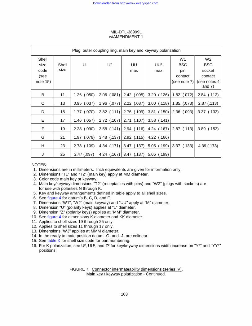
MIL-DTL-38999L w/AMENDMENT 1
103
Plug, outer coupling ring, main key and keyway polarization
Shell size code (see
note 15)
Shell size
U
U²
UU max
UU² max
W1 BSC pin
contact (see note 7)
W2 BSC
socket contact
(see notes 4 and 7)
B 11 1.26 (.050) 2.06 (.081) 2.42 (.095) 3.20 (.126) 1.82 (.072) 2.84 (.112)
C 13 0.95 (.037) 1.96 (.077) 2.22 (.087) 3.00 (.118) 1.85 (.073) 2.87 (.113)
D 15 1.77 (.070) 2.82 (.111) 2.76 (.109) 3.81 (.150) 2.36 (.093) 3.37 (.133)
E 17 1.46 (.057) 2.72 (.107) 2.71 (.107) 3.58 (.141)
F 19 2.28 (.090) 3.58 (.141) 2.94 (.116) 4.24 (.167) 2.87 (.113) 3.89 (.153)
G 21 1.97 (.078) 3.48 (.137) 2.92 (.115) 4.22 (.166)
H 23 2.78 (.109) 4.34 (.171) 3.47 (.137) 5.05 (.199) 3.37 (.133) 4.39 (.173)
J 25 2.47 (.097) 4.24 (.167) 3.47 (.137) 5.05 (.199) NOTES: 1. Dimensions are in millimeters. Inch equivalents are given for information only. 2. Dimensions "T1" and "T2" (main key) apply at MM diameter. 3. Color code main key or keyway. 4. Main key/keyway dimensions "T2" (receptacles with pins) and "W2" (plugs with sockets) are
for use with polarities N through K. 5. Key and keyway arrangements defined in table apply to all shell sizes. 6. See figure 4 for datum’s B, C, D, and F. 7. Dimensions "W1", "W2" (main keyway) and "UU" apply at "M" diameter. 8. Dimension "U" (polarity keys) applies at "L" diameter. 9. Dimension "Z" (polarity keys) applies at "MM" diameter.
10. See figure 4 for dimensions K diameter and KK diameter. 11. Applies to shell sizes 19 through 25 only. 12. Applies to shell sizes 11 through 17 only. 13. Dimensions "W3" applies at MMM diameter. 14. In the ready to mate position datum -G- and -J- are colinear. 15. See table X for shell size code for part numbering. 16. For K polarization, see U², UU², and Z² for key/keyway dimensions width increase on "Y°" and "YY°"
positions.
FIGURE 7. Connector intermateability dimensions (series IV). Main key / keyway polarization - Continued.
Downloaded from http://www.everyspec.com
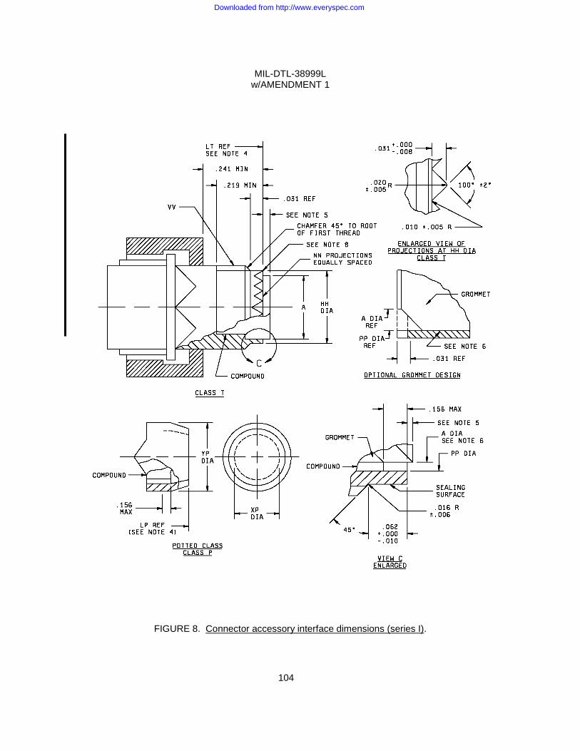
MIL-DTL-38999L w/AMENDMENT 1
104
FIGURE 8. Connector accessory interface dimensions (series I).
Downloaded from http://www.everyspec.com
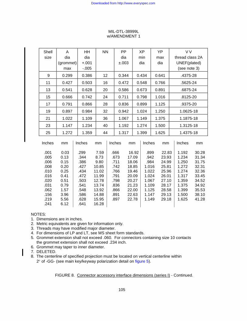
MIL-DTL-38999L w/AMENDMENT 1
105
Inches mm Inches mm Inches mm Inches mm Inches mm
.001 .005 .006 .008 .010 .016 .020 .031 .062 .156 .219 .241
0.03 0.13 0.15 0.20 0.25 0.41 0.51 0.79 1.57 3.96 5.56 6.12
.299 .344 .386 .427 .434 .472 .503 .541 .548 .586 .628 .641
7.59 8.73 9.80 10.85 11.02 11.99 12.78 13.74 13.92 14.88 15.95 16.28
.666 .673 .711 .742 .766 .791 .798 .836 .866 .891 .897
16.92 17.09 18.06 18.85 19.46 20.09 20.27 21.23 22.00 22.63 22.78
.899 .942 .984 1.016 1.022 1.024 1.067 1.109 1.125 1.147 1.149
22.83 23.93 24.99 25.81 25.96 26.01 27.10 28.17 28.58 29.13 29.18
1.192 1.234 1.250 1.272 1.274 1.317 1.359 1.375 1.399 1.500 1.625
30.28 31.34 31.75 32.31 32.36 33.45 34.52 34.92 35.53 38.10 41.28
NOTES: 1. Dimensions are in inches. 2. Metric equivalents are given for information only. 3. Threads may have modified major diameter. 4. For dimensions of LP and LT, see MS sheet form standards. 5. Grommet extension shall not exceed .060. For connectors containing size 10 contacts the grommet extension shall not exceed .234 inch. 6. Grommet may taper to inner diameter. 7. DELETED. 8. The centerline of specified projection must be located on vertical centerline within 2° of -GG- (see main key/keyway polarization detail on figure 5).
FIGURE 8. Connector accessory interface dimensions (series I) - Continued.
Shell size
A dia
(grommet) max
HH dia
+.001 -.005
NN PP dia
±.003
XP min dia
YP max dia
V V thread class 2A UNEF(plated) (see note 3)
9 0.299 0.386 12 0.344 0.434 0.641 .4375-28
11 0.427 0.503 16 0.472 0.548 0.766 .5625-24
13 0.541 0.628 20 0.586 0.673 0.891 .6875-24
15 0.666 0.742 24 0.711 0.798 1.016 .8125-20
17 0.791 0.866 28 0.836 0.899 1.125 .9375-20
19 0.897 0.984 32 0.942 1.024 1.250 1.0625-18
21 1.022 1.109 36 1.067 1.149 1.375 1.1875-18
23 1.147 1.234 40 1.192 1.274 1.500 1.3125-18
25 1.272 1.359 44 1.317 1.399 1.625 1.4375-18
Downloaded from http://www.everyspec.com
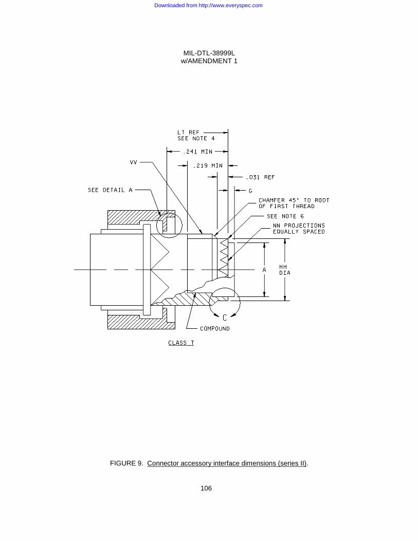
MIL-DTL-38999L w/AMENDMENT 1
106
FIGURE 9. Connector accessory interface dimensions (series II).
Downloaded from http://www.everyspec.com
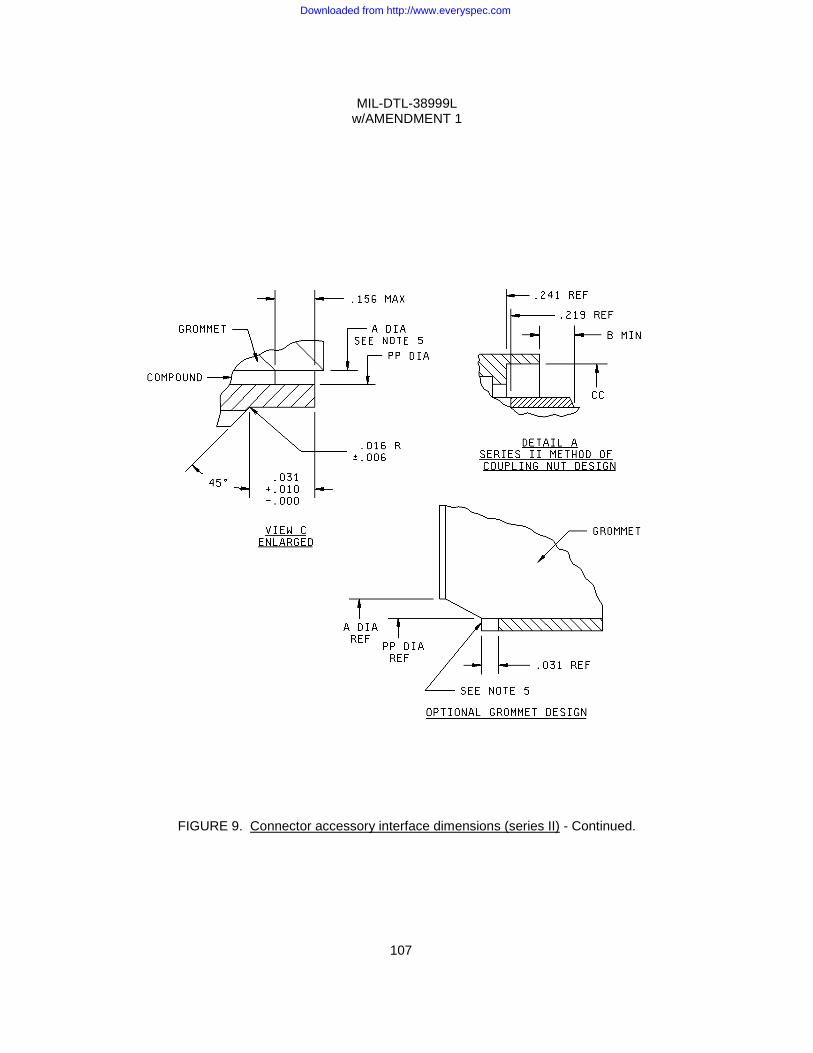
MIL-DTL-38999L w/AMENDMENT 1
107
FIGURE 9. Connector accessory interface dimensions (series II) - Continued.
Downloaded from http://www.everyspec.com
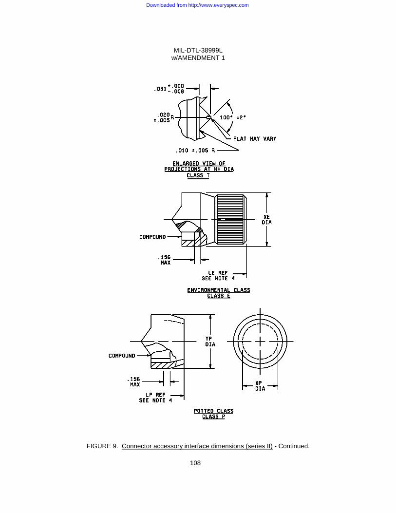
MIL-DTL-38999L w/AMENDMENT 1
108
FIGURE 9. Connector accessory interface dimensions (series II) - Continued.
Downloaded from http://www.everyspec.com
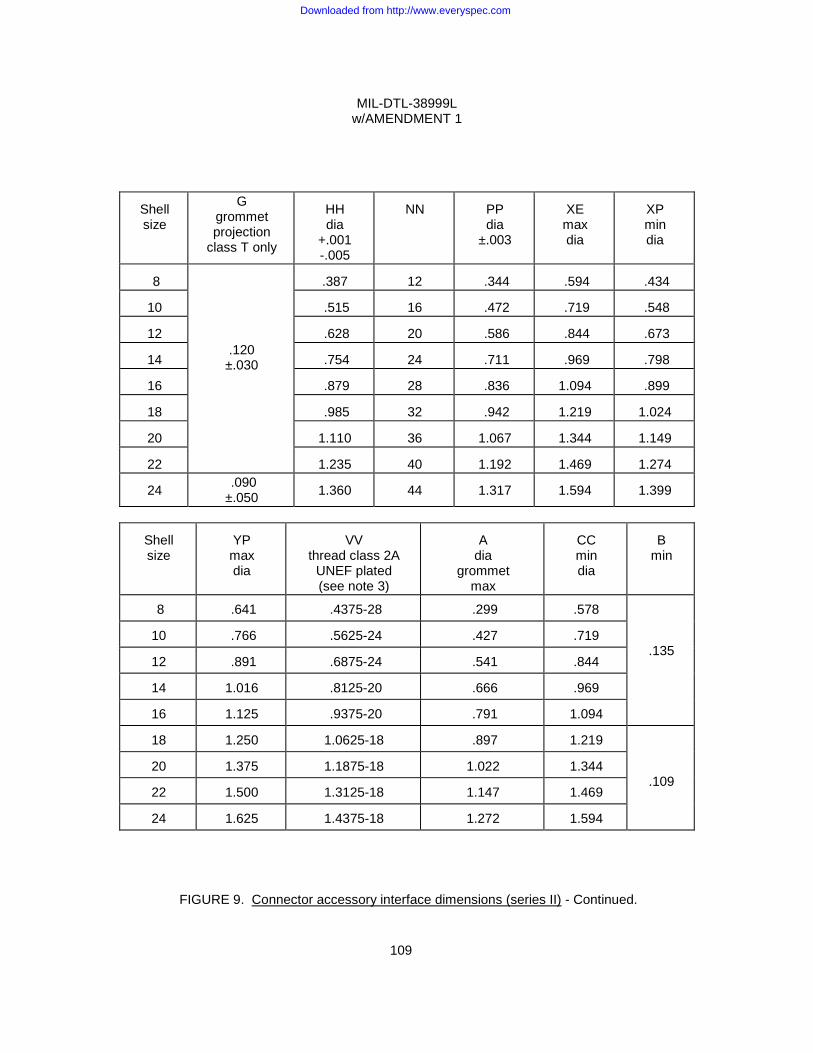
MIL-DTL-38999L w/AMENDMENT 1
109
Shell size
G grommet projection
class T only
HH dia
+.001 -.005
NN
PP dia
±.003
XE max dia
XP min dia
8
.120 ±.030
.387
12
.344
.594
.434
10
.515
16
.472
.719
.548
12
.628
20
.586
.844
.673
14
.754
24
.711
.969
.798
16
.879
28
.836
1.094
.899
18
.985
32
.942
1.219
1.024
20
1.110
36
1.067
1.344
1.149
22
1.235
40
1.192
1.469
1.274
24 .090
±.050
1.360
44
1.317
1.594
1.399
Shell size
YP max dia
VV
thread class 2A UNEF plated (see note 3)
A
dia grommet
max
CC min dia
B
min
8 .641 .4375-28 .299 .578
.135 10 .766 .5625-24 .427 .719
12 .891 .6875-24 .541 .844
14 1.016 .8125-20 .666 .969
16 1.125 .9375-20 .791 1.094
18 1.250 1.0625-18 .897 1.219
.109 20 1.375 1.1875-18 1.022 1.344
22 1.500 1.3125-18 1.147 1.469
24 1.625 1.4375-18 1.272 1.594
FIGURE 9. Connector accessory interface dimensions (series II) - Continued.
Downloaded from http://www.everyspec.com
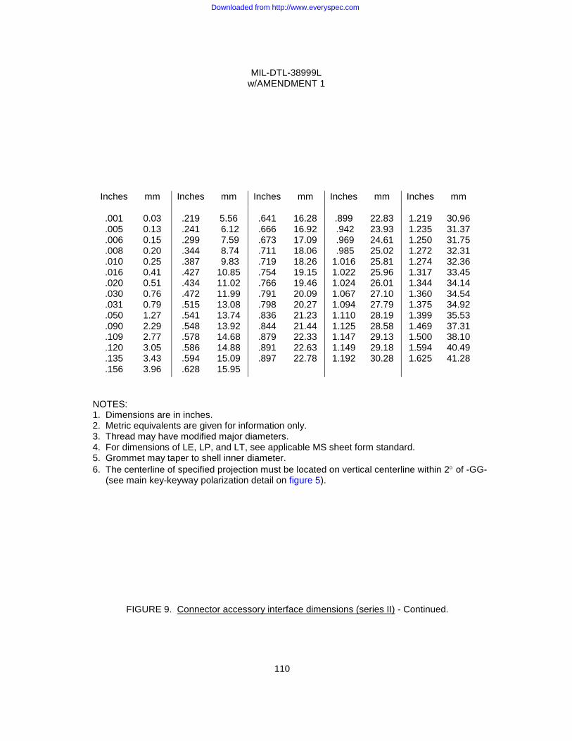
MIL-DTL-38999L w/AMENDMENT 1
110
Inches mm Inches mm Inches mm Inches mm Inches mm
.001
.005
.006
.008
.010
.016
.020
.030
.031
.050
.090
.109
.120
.135
.156
0.03 0.13 0.15 0.20 0.25 0.41 0.51 0.76 0.79 1.27 2.29 2.77 3.05 3.43 3.96
.219 .241 .299 .344 .387 .427 .434 .472 .515 .541 .548 .578 .586 .594 .628
5.56 6.12 7.59 8.74 9.83 10.85 11.02 11.99 13.08 13.74 13.92 14.68 14.88 15.09 15.95
.641 .666 .673 .711 .719 .754 .766 .791 .798 .836 .844 .879 .891 .897
16.28 16.92 17.09 18.06 18.26 19.15 19.46 20.09 20.27 21.23 21.44 22.33 22.63 22.78
.899 .942 .969 .985 1.016 1.022 1.024 1.067 1.094 1.110 1.125 1.147 1.149 1.192
22.83 23.93 24.61 25.02 25.81 25.96 26.01 27.10 27.79 28.19 28.58 29.13 29.18 30.28
1.219 1.235 1.250 1.272 1.274 1.317 1.344 1.360 1.375 1.399 1.469 1.500 1.594 1.625
30.96 31.37 31.75 32.31 32.36 33.45 34.14 34.54 34.92 35.53 37.31 38.10 40.49 41.28
NOTES: 1. Dimensions are in inches. 2. Metric equivalents are given for information only. 3. Thread may have modified major diameters. 4. For dimensions of LE, LP, and LT, see applicable MS sheet form standard. 5. Grommet may taper to shell inner diameter. 6. The centerline of specified projection must be located on vertical centerline within 2° of -GG- (see main key-keyway polarization detail on figure 5).
FIGURE 9. Connector accessory interface dimensions (series II) - Continued.
Downloaded from http://www.everyspec.com
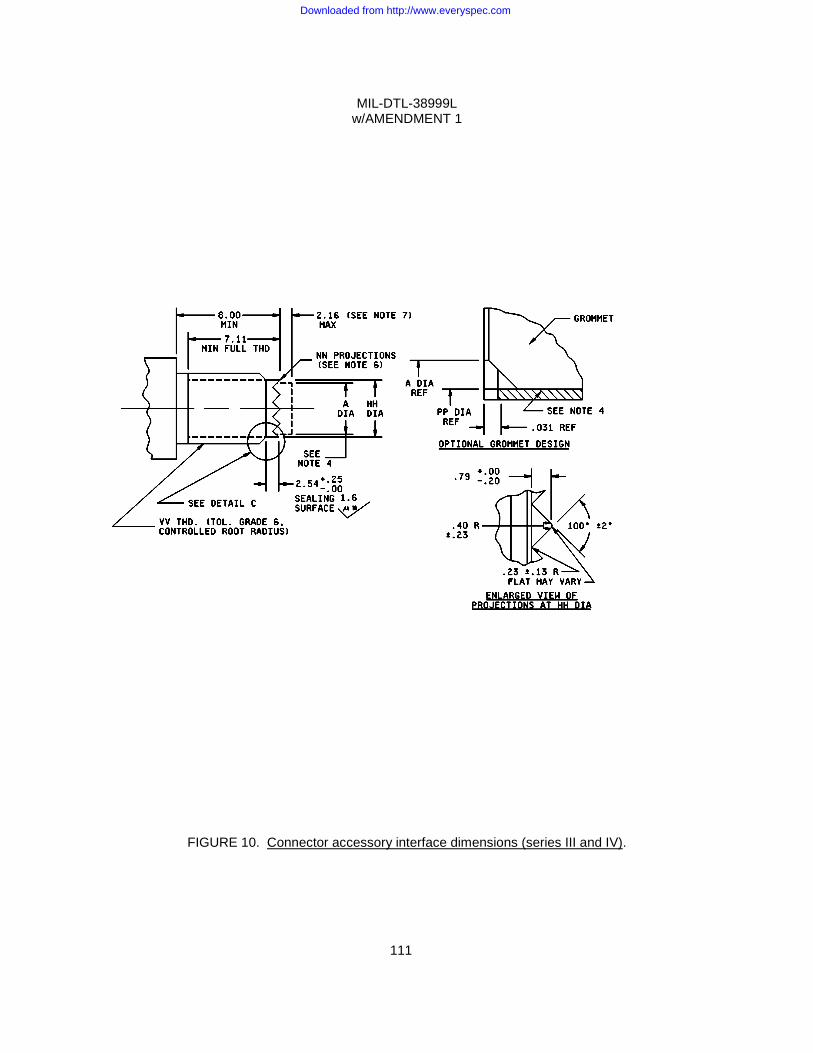
MIL-DTL-38999L w/AMENDMENT 1
111
FIGURE 10. Connector accessory interface dimensions (series III and IV).
Downloaded from http://www.everyspec.com
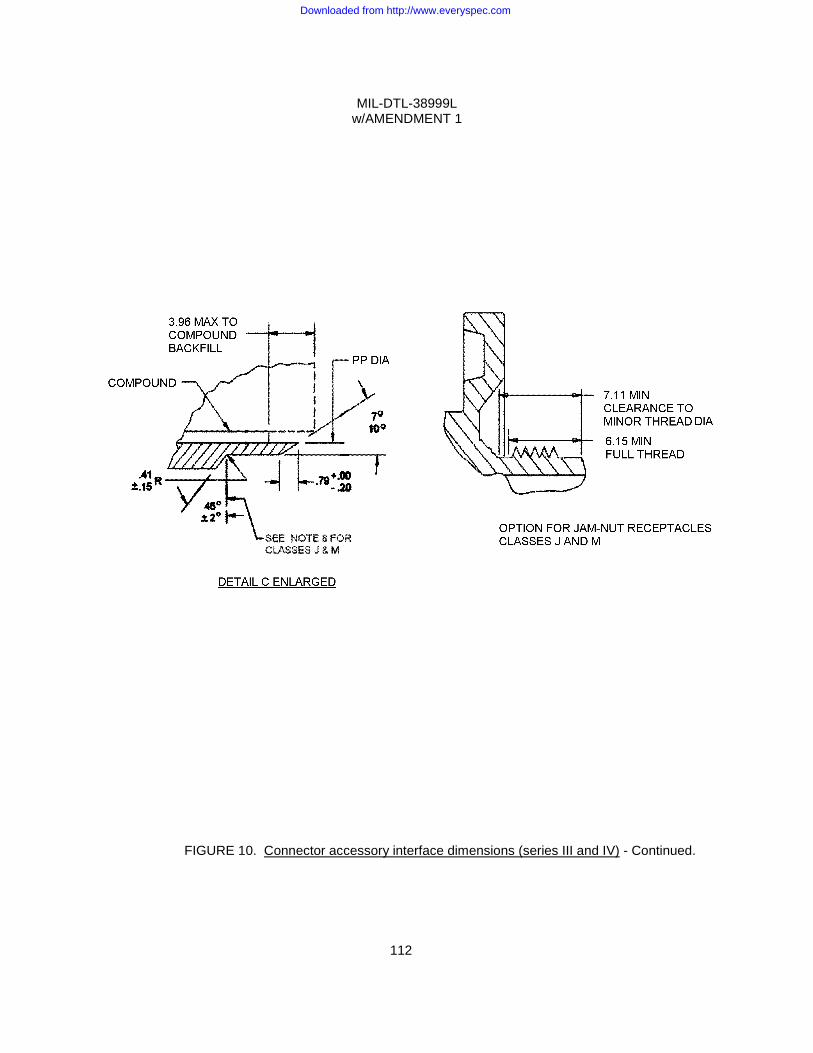
MIL-DTL-38999L w/AMENDMENT 1
112
FIGURE 10. Connector accessory interface dimensions (series III and IV) - Continued.
Downloaded from http://www.everyspec.com
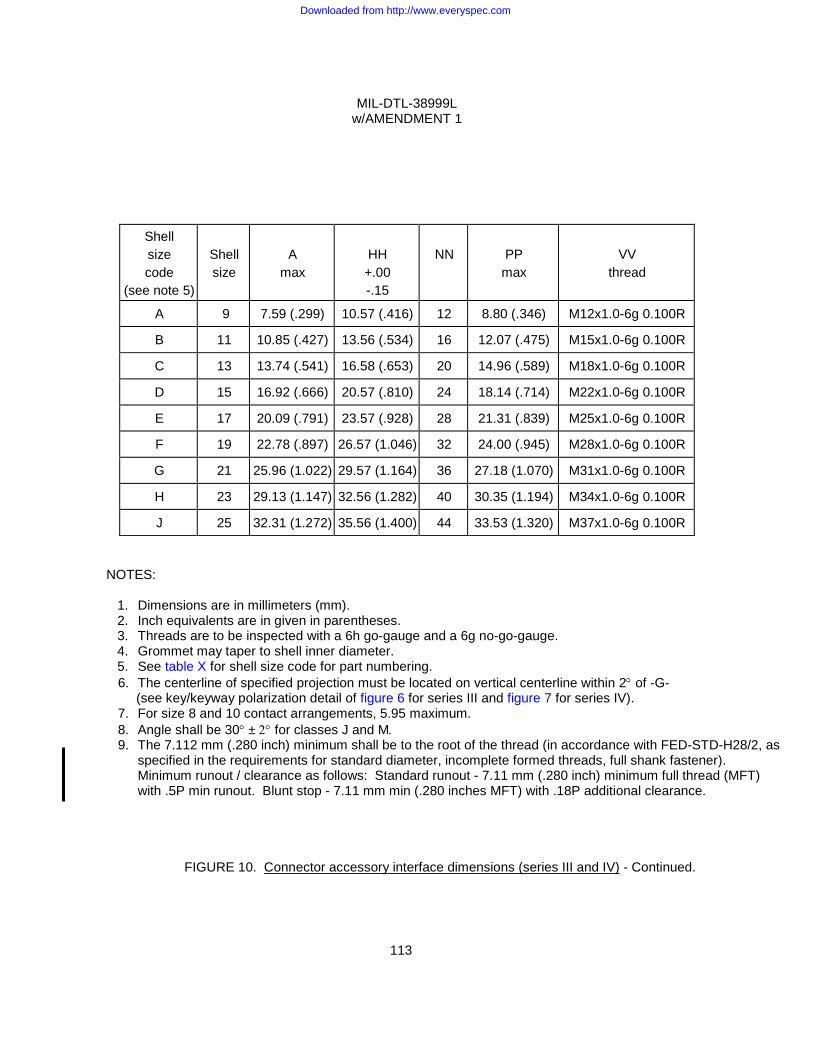
MIL-DTL-38999L w/AMENDMENT 1
113
Shell size code
(see note 5)
Shell size
A
max
HH +.00 -.15
NN
PP max
VV
thread
A 9 7.59 (.299) 10.57 (.416) 12 8.80 (.346) M12x1.0-6g 0.100R
B 11 10.85 (.427) 13.56 (.534) 16 12.07 (.475) M15x1.0-6g 0.100R
C 13 13.74 (.541) 16.58 (.653) 20 14.96 (.589) M18x1.0-6g 0.100R
D 15 16.92 (.666) 20.57 (.810) 24 18.14 (.714) M22x1.0-6g 0.100R
E 17 20.09 (.791) 23.57 (.928) 28 21.31 (.839) M25x1.0-6g 0.100R
F 19 22.78 (.897) 26.57 (1.046) 32 24.00 (.945) M28x1.0-6g 0.100R
G 21 25.96 (1.022) 29.57 (1.164) 36 27.18 (1.070) M31x1.0-6g 0.100R
H 23 29.13 (1.147) 32.56 (1.282) 40 30.35 (1.194) M34x1.0-6g 0.100R
J 25 32.31 (1.272) 35.56 (1.400) 44 33.53 (1.320) M37x1.0-6g 0.100R NOTES: 1. Dimensions are in millimeters (mm). 2. Inch equivalents are in given in parentheses. 3. Threads are to be inspected with a 6h go-gauge and a 6g no-go-gauge. 4. Grommet may taper to shell inner diameter. 5. See table X for shell size code for part numbering.
6. The centerline of specified projection must be located on vertical centerline within 2° of -G- (see key/keyway polarization detail of figure 6 for series III and figure 7 for series IV). 7. For size 8 and 10 contact arrangements, 5.95 maximum. 8. Angle shall be 30° ± 2° for classes J and M. 9. The 7.112 mm (.280 inch) minimum shall be to the root of the thread (in accordance with FED-STD-H28/2, as
specified in the requirements for standard diameter, incomplete formed threads, full shank fastener). Minimum runout / clearance as follows: Standard runout - 7.11 mm (.280 inch) minimum full thread (MFT) with .5P min runout. Blunt stop - 7.11 mm min (.280 inches MFT) with .18P additional clearance.
FIGURE 10. Connector accessory interface dimensions (series III and IV) - Continued.
Downloaded from http://www.everyspec.com
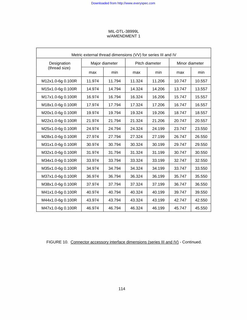
MIL-DTL-38999L w/AMENDMENT 1
114
Metric external thread dimensions (VV) for series III and IV
Designation (thread size)
Major diameter
Pitch diameter
Minor diameter
max
min
max
min
max
min
M12x1.0-6g 0.100R 11.974 11.794 11.324 11.206 10.747 10.557
M15x1.0-6g 0.100R 14.974 14.794 14.324 14.206 13.747 13.557
M17x1.0-6g 0.100R 16.974 16.794 16.324 16.206 15.747 15.557
M18x1.0-6g 0.100R 17.974 17.794 17.324 17.206 16.747 16.557
M20x1.0-6g 0.100R 19.974 19.794 19.324 19.206 18.747 18.557
M22x1.0-6g 0.100R 21.974 21.794 21.324 21.206 20.747 20.557
M25x1.0-6g 0.100R 24.974 24.794 24.324 24.199 23.747 23.550
M28x1.0-6g 0.100R 27.974 27.794 27.324 27.199 26.747 26.550
M31x1.0-6g 0.100R 30.974 30.794 30.324 30.199 29.747 29.550
M32x1.0-6g 0.100R 31.974 31.794 31.324 31.199 30.747 30.550
M34x1.0-6g 0.100R 33.974 33.794 33.324 33.199 32.747 32.550
M35x1.0-6g 0.100R 34.974 34.794 34.324 34.199 33.747 33.550
M37x1.0-6g 0.100R 36.974 36.794 36.324 36.199 35.747 35.550
M38x1.0-6g 0.100R 37.974 37.794 37.324 37.199 36.747 36.550
M41x1.0-6g 0.100R 40.974 40.794 40.324 40.199 39.747 39.550
M44x1.0-6g 0.100R 43.974 43.794 43.324 43.199 42.747 42.550
M47x1.0-6g 0.100R 46.974 46.794 46.324 46.199 45.747 45.550
FIGURE 10. Connector accessory interface dimensions (series III and IV) - Continued.
Downloaded from http://www.everyspec.com
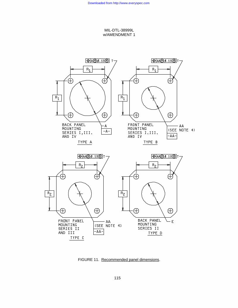
MIL-DTL-38999L w/AMENDMENT 1
115
FIGURE 11. Recommended panel dimensions.
Downloaded from http://www.everyspec.com
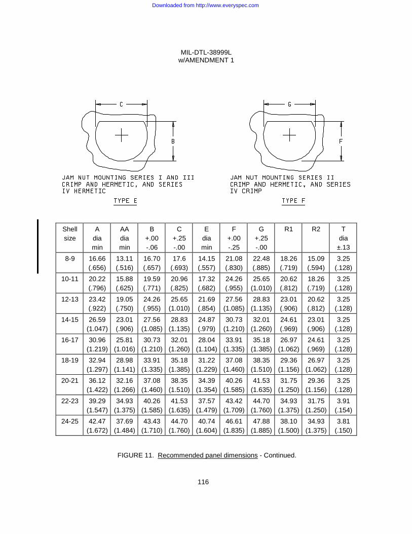
MIL-DTL-38999L w/AMENDMENT 1
116
Shell size
A dia min
AA dia min
B +.00 -.06
C +.25 -.00
E dia min
F +.00 -.25
G +.25 -.00
R1 R2 T dia
±.13
8-9 16.66 (.656)
13.11 (.516)
16.70 (.657)
17.6 (.693)
14.15 (.557)
21.08 (.830)
22.48 (.885)
18.26 (.719)
15.09 (.594)
3.25 (.128)
10-11 20.22 (.796)
15.88 (.625)
19.59 (.771)
20.96 (.825)
17.32 (.682)
24.26 (.955)
25.65 (1.010)
20.62 (.812)
18.26 (.719)
3.25 (.128)
12-13 23.42 (.922)
19.05 (.750)
24.26 (.955)
25.65 (1.010)
21.69 (.854)
27.56 (1.085)
28.83 (1.135)
23.01 (.906)
20.62 (.812)
3.25 (.128)
14-15 26.59 (1.047)
23.01 (.906)
27.56 (1.085)
28.83 (1.135)
24.87 (.979)
30.73 (1.210)
32.01 (1.260)
24.61 (.969)
23.01 (.906)
3.25 (.128)
16-17 30.96 (1.219)
25.81 (1.016)
30.73 (1.210)
32.01 (1.260)
28.04 (1.104)
33.91 (1.335)
35.18 (1.385)
26.97 (1.062)
24.61 (.969)
3.25 (.128)
18-19 32.94 (1.297)
28.98 (1.141)
33.91 (1.335)
35.18 (1.385)
31.22 (1.229)
37.08 (1.460)
38.35 (1.510)
29.36 (1.156)
26.97 (1.062)
3.25 (.128)
20-21 36.12 (1.422)
32.16 (1.266)
37.08 (1.460)
38.35 (1.510)
34.39 (1.354)
40.26 (1.585)
41.53 (1.635)
31.75 (1.250)
29.36 (1.156)
3.25 (.128)
22-23 39.29 (1.547)
34.93 (1.375)
40.26 (1.585)
41.53 (1.635)
37.57 (1.479)
43.42 (1.709)
44.70 (1.760)
34.93 (1.375)
31.75 (1.250)
3.91 (.154)
24-25 42.47 (1.672)
37.69 (1.484)
43.43 (1.710)
44.70 (1.760)
40.74 (1.604)
46.61 (1.835)
47.88 (1.885)
38.10 (1.500)
34.93 (1.375)
3.81 (.150)
FIGURE 11. Recommended panel dimensions - Continued.
Downloaded from http://www.everyspec.com
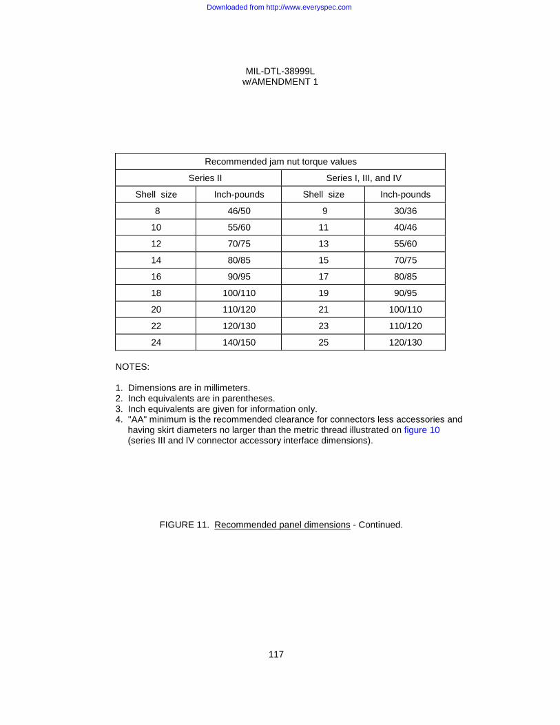
MIL-DTL-38999L w/AMENDMENT 1
117
Recommended jam nut torque values
Series II
Series I, III, and IV
Shell size
Inch-pounds
Shell size
Inch-pounds
8
46/50
9
30/36
10
55/60
11
40/46
12
70/75
13
55/60
14
80/85
15
70/75
16
90/95
17
80/85
18
100/110
19
90/95
20
110/120
21
100/110
22
120/130
23
110/120
24
140/150
25
120/130 NOTES: 1. Dimensions are in millimeters. 2. Inch equivalents are in parentheses. 3. Inch equivalents are given for information only. 4. "AA" minimum is the recommended clearance for connectors less accessories and
having skirt diameters no larger than the metric thread illustrated on figure 10 (series III and IV connector accessory interface dimensions).
FIGURE 11. Recommended panel dimensions - Continued.
Downloaded from http://www.everyspec.com
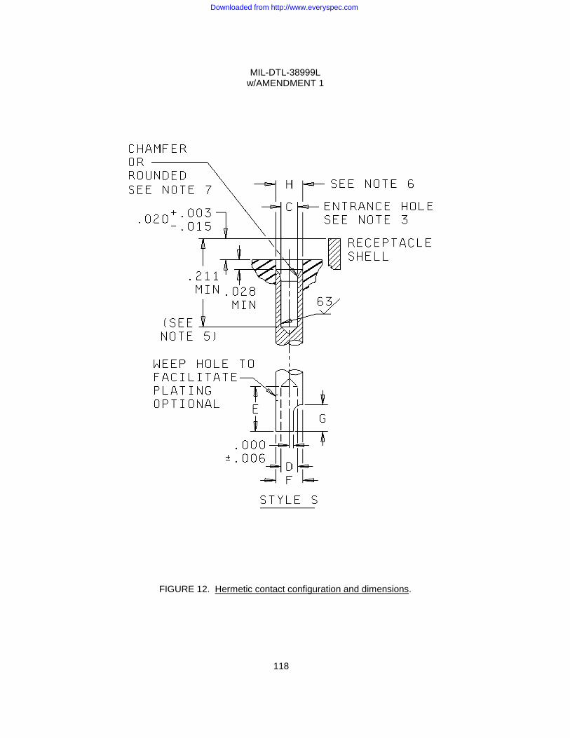
MIL-DTL-38999L w/AMENDMENT 1
118
FIGURE 12. Hermetic contact configuration and dimensions.
Downloaded from http://www.everyspec.com
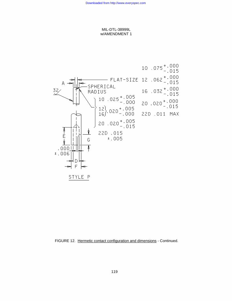
MIL-DTL-38999L w/AMENDMENT 1
119
FIGURE 12. Hermetic contact configuration and dimensions - Continued.
Downloaded from http://www.everyspec.com

MIL-DTL-38999L w/AMENDMENT 1
120
FIGURE 12. Hermetic contact configuration and dimensions - Continued.
Downloaded from http://www.everyspec.com
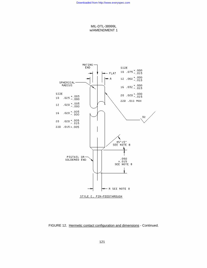
MIL-DTL-38999L w/AMENDMENT 1
121
FIGURE 12. Hermetic contact configuration and dimensions - Continued.
Downloaded from http://www.everyspec.com
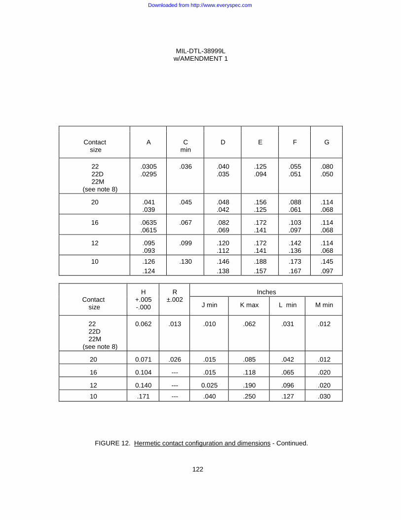
MIL-DTL-38999L w/AMENDMENT 1
122
Contact
size
A
C min
D
E
F
G
22 22D 22M
(see note 8)
.0305 .0295
.036
.040 .035
.125 .094
.055 .051
.080 .050
20
.041 .039
.045
.048 .042
.156 .125
.088 .061
.114 .068
16
.0635 .0615
.067
.082 .069
.172 .141
.103 .097
.114 .068
12
.095 .093
.099
.120 .112
.172 .141
.142 .136
.114 .068
10 .126 .124
.130 .146 .138
.188
.157 .173 .167
.145
.097
Contact size
H
+.005 -.000
R
±.002
Inches
J min
K max
L min
M min
22 22D 22M
(see note 8)
0.062
.013
.010
.062
.031
.012
20
0.071
.026
.015
.085
.042
.012
16
0.104
---
.015
.118
.065
.020
12
0.140
---
0.025
.190
.096
.020
10 .171 --- .040 .250 .127 .030
FIGURE 12. Hermetic contact configuration and dimensions - Continued.
Downloaded from http://www.everyspec.com
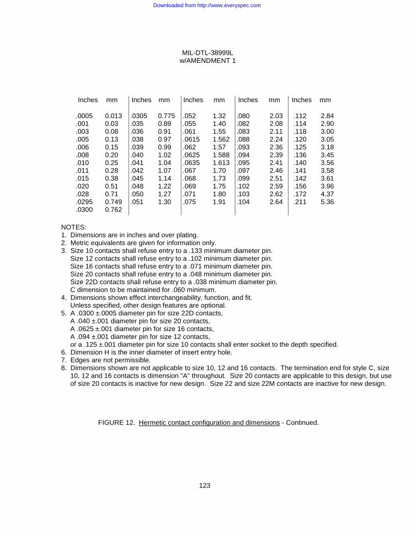
MIL-DTL-38999L w/AMENDMENT 1
123
Inches
mm
Inches
mm
Inches
mm
Inches
mm
Inches
mm
.0005
.001
.003
.005
.006
.008
.010
.011
.015
.020
.028
.0295
.0300
0.013 0.03 0.08 0.13 0.15 0.20 0.25 0.28 0.38 0.51 0.71 0.749 0.762
.0305 .035 .036 .038 .039 .040 .041 .042 .045 .048 .050 .051
0.775 0.89 0.91 0.97 0.99 1.02 1.04 1.07 1.14 1.22 1.27 1.30
.052 .055 .061 .0615 .062 .0625 .0635 .067 .068 .069 .071 .075
1.32 1.40 1.55 1.562 1.57 1.588 1.613 1.70 1.73 1.75 1.80 1.91
.080 .082 .083 .088 .093 .094 .095 .097 .099 .102 .103 .104
2.03 2.08 2.11 2.24 2.36 2.39 2.41 2.46 2.51 2.59 2.62 2.64
.112 .114 .118 .120 .125 .136 .140 .141 .142 .156 .172 .211
2.84 2.90 3.00 3.05 3.18 3.45 3.56 3.58 3.61 3.96 4.37 5.36
NOTES: 1. Dimensions are in inches and over plating. 2. Metric equivalents are given for information only. 3. Size 10 contacts shall refuse entry to a .133 minimum diameter pin.
Size 12 contacts shall refuse entry to a .102 minimum diameter pin. Size 16 contacts shall refuse entry to a .071 minimum diameter pin. Size 20 contacts shall refuse entry to a .048 minimum diameter pin. Size 22D contacts shall refuse entry to a .038 minimum diameter pin. C dimension to be maintained for .060 minimum.
4. Dimensions shown effect interchangeability, function, and fit. Unless specified, other design features are optional.
5. A .0300 ±.0005 diameter pin for size 22D contacts, A .040 ±.001 diameter pin for size 20 contacts, A .0625 ±.001 diameter pin for size 16 contacts, A .094 ±.001 diameter pin for size 12 contacts, or a .125 ±.001 diameter pin for size 10 contacts shall enter socket to the depth specified.
6. Dimension H is the inner diameter of insert entry hole. 7. Edges are not permissible. 8. Dimensions shown are not applicable to size 10, 12 and 16 contacts. The termination end for style C, size
10, 12 and 16 contacts is dimension "A" throughout. Size 20 contacts are applicable to this design, but use of size 20 contacts is inactive for new design. Size 22 and size 22M contacts are inactive for new design.
FIGURE 12. Hermetic contact configuration and dimensions - Continued.
Downloaded from http://www.everyspec.com
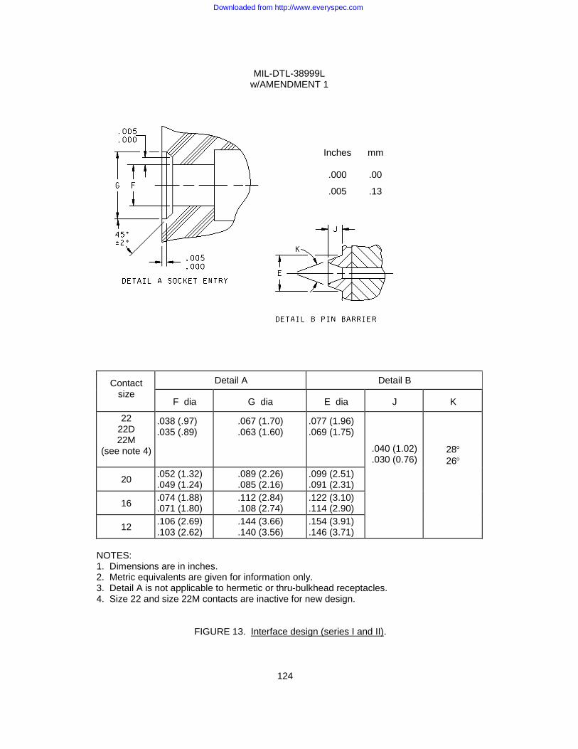
MIL-DTL-38999L w/AMENDMENT 1
124
Contact
size
Detail A Detail B
F dia
G dia
E dia
J
K
22 22D 22M
(see note 4)
.038 (.97)
.035 (.89) .067 (1.70) .063 (1.60)
.077 (1.96)
.069 (1.75)
.040 (1.02)
.030 (0.76)
28° 26°
20 .052 (1.32)
.049 (1.24) .089 (2.26) .085 (2.16)
.099 (2.51)
.091 (2.31)
16 .074 (1.88)
.071 (1.80) .112 (2.84) .108 (2.74)
.122 (3.10)
.114 (2.90)
12 .106 (2.69) .103 (2.62)
.144 (3.66)
.140 (3.56) .154 (3.91) .146 (3.71)
NOTES: 1. Dimensions are in inches. 2. Metric equivalents are given for information only. 3. Detail A is not applicable to hermetic or thru-bulkhead receptacles. 4. Size 22 and size 22M contacts are inactive for new design.
FIGURE 13. Interface design (series I and II).
Inches mm
.000 .00
.005 .13
Downloaded from http://www.everyspec.com
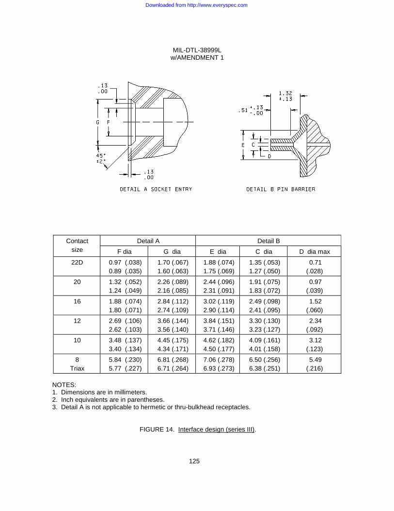
MIL-DTL-38999L w/AMENDMENT 1
125
Contact size
Detail A Detail B F dia G dia E dia C dia D dia max
22D 0.97 (.038) 0.89 (.035)
1.70 (.067) 1.60 (.063)
1.88 (.074) 1.75 (.069)
1.35 (.053) 1.27 (.050)
0.71 (.028)
20 1.32 (.052) 1.24 (.049)
2.26 (.089) 2.16 (.085)
2.44 (.096) 2.31 (.091)
1.91 (.075) 1.83 (.072)
0.97 (.039)
16 1.88 (.074) 1.80 (.071)
2.84 (.112) 2.74 (.109)
3.02 (.119) 2.90 (.114)
2.49 (.098) 2.41 (.095)
1.52 (.060)
12 2.69 (.106) 2.62 (.103)
3.66 (.144) 3.56 (.140)
3.84 (.151) 3.71 (.146)
3.30 (.130) 3.23 (.127)
2.34 (.092)
10 3.48 (.137) 3.40 (.134)
4.45 (.175) 4.34 (.171)
4.62 (.182) 4.50 (.177)
4.09 (.161) 4.01 (.158)
3.12 (.123)
8 Triax
5.84 (.230) 5.77 (.227)
6.81 (.268) 6.71 (.264)
7.06 (.278) 6.93 (.273)
6.50 (.256) 6.38 (.251)
5.49 (.216)
NOTES: 1. Dimensions are in millimeters. 2. Inch equivalents are in parentheses. 3. Detail A is not applicable to hermetic or thru-bulkhead receptacles.
FIGURE 14. Interface design (series III).
Downloaded from http://www.everyspec.com
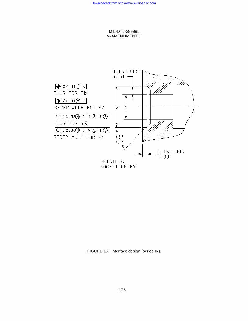
MIL-DTL-38999L w/AMENDMENT 1
126
FIGURE 15. Interface design (series IV).
Downloaded from http://www.everyspec.com
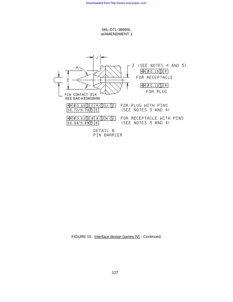
MIL-DTL-38999L w/AMENDMENT 1
127
FIGURE 15. Interface design (series IV) - Continued.
Downloaded from http://www.everyspec.com
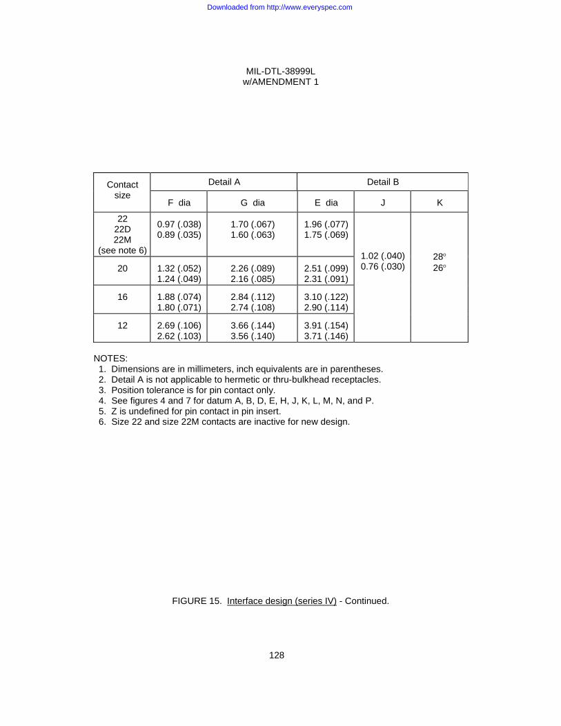
MIL-DTL-38999L w/AMENDMENT 1
128
Contact
size
Detail A Detail B
F dia
G dia
E dia
J
K
22 22D 22M
(see note 6)
0.97 (.038) 0.89 (.035)
1.70 (.067) 1.60 (.063)
1.96 (.077) 1.75 (.069)
1.02 (.040) 0.76 (.030)
28° 26°
20
1.32 (.052) 1.24 (.049)
2.26 (.089) 2.16 (.085)
2.51 (.099) 2.31 (.091)
16
1.88 (.074) 1.80 (.071)
2.84 (.112) 2.74 (.108)
3.10 (.122) 2.90 (.114)
12
2.69 (.106) 2.62 (.103)
3.66 (.144) 3.56 (.140)
3.91 (.154) 3.71 (.146)
NOTES: 1. Dimensions are in millimeters, inch equivalents are in parentheses. 2. Detail A is not applicable to hermetic or thru-bulkhead receptacles. 3. Position tolerance is for pin contact only. 4. See figures 4 and 7 for datum A, B, D, E, H, J, K, L, M, N, and P. 5. Z is undefined for pin contact in pin insert. 6. Size 22 and size 22M contacts are inactive for new design.
FIGURE 15. Interface design (series IV) - Continued.
Downloaded from http://www.everyspec.com
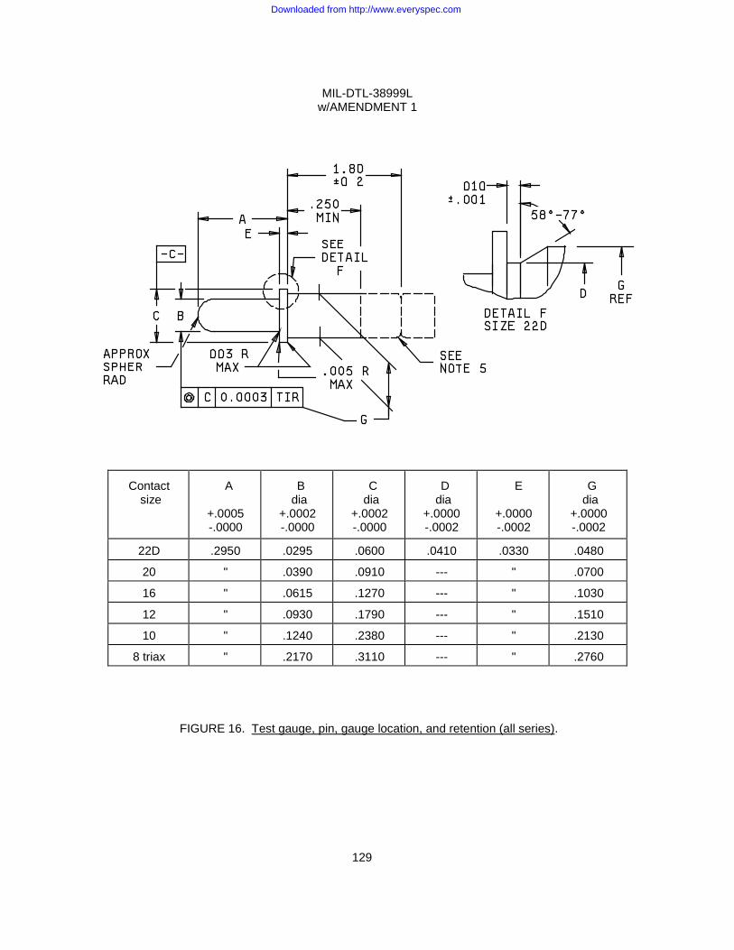
MIL-DTL-38999L w/AMENDMENT 1
129
Contact
size
A
+.0005 -.0000
B dia
+.0002 -.0000
C dia
+.0002 -.0000
D dia
+.0000 -.0002
E
+.0000 -.0002
G dia
+.0000 -.0002
22D .2950 .0295 .0600 .0410 .0330 .0480
20 " .0390 .0910 --- " .0700
16 " .0615 .1270 --- " .1030
12 " .0930 .1790 --- " .1510
10 " .1240 .2380 --- " .2130
8 triax " .2170 .3110 --- " .2760
FIGURE 16. Test gauge, pin, gauge location, and retention (all series).
Downloaded from http://www.everyspec.com
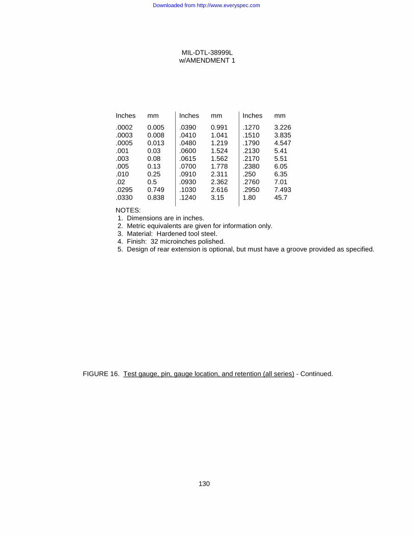
MIL-DTL-38999L w/AMENDMENT 1
130
Inches mm Inches mm Inches mm
.0002
.0003
.0005
.001
.003
.005
.010
.02
.0295
.0330
0.005 0.008 0.013 0.03 0.08 0.13 0.25 0.5 0.749 0.838
.0390
.0410
.0480
.0600
.0615
.0700
.0910
.0930
.1030
.1240
0.991 1.041 1.219 1.524 1.562 1.778 2.311 2.362 2.616 3.15
.1270
.1510
.1790
.2130
.2170
.2380
.250
.2760
.2950 1.80
3.226 3.835 4.547 5.41 5.51 6.05 6.35 7.01 7.493 45.7
NOTES: 1. Dimensions are in inches. 2. Metric equivalents are given for information only. 3. Material: Hardened tool steel. 4. Finish: 32 microinches polished. 5. Design of rear extension is optional, but must have a groove provided as specified.
FIGURE 16. Test gauge, pin, gauge location, and retention (all series) - Continued.
Downloaded from http://www.everyspec.com
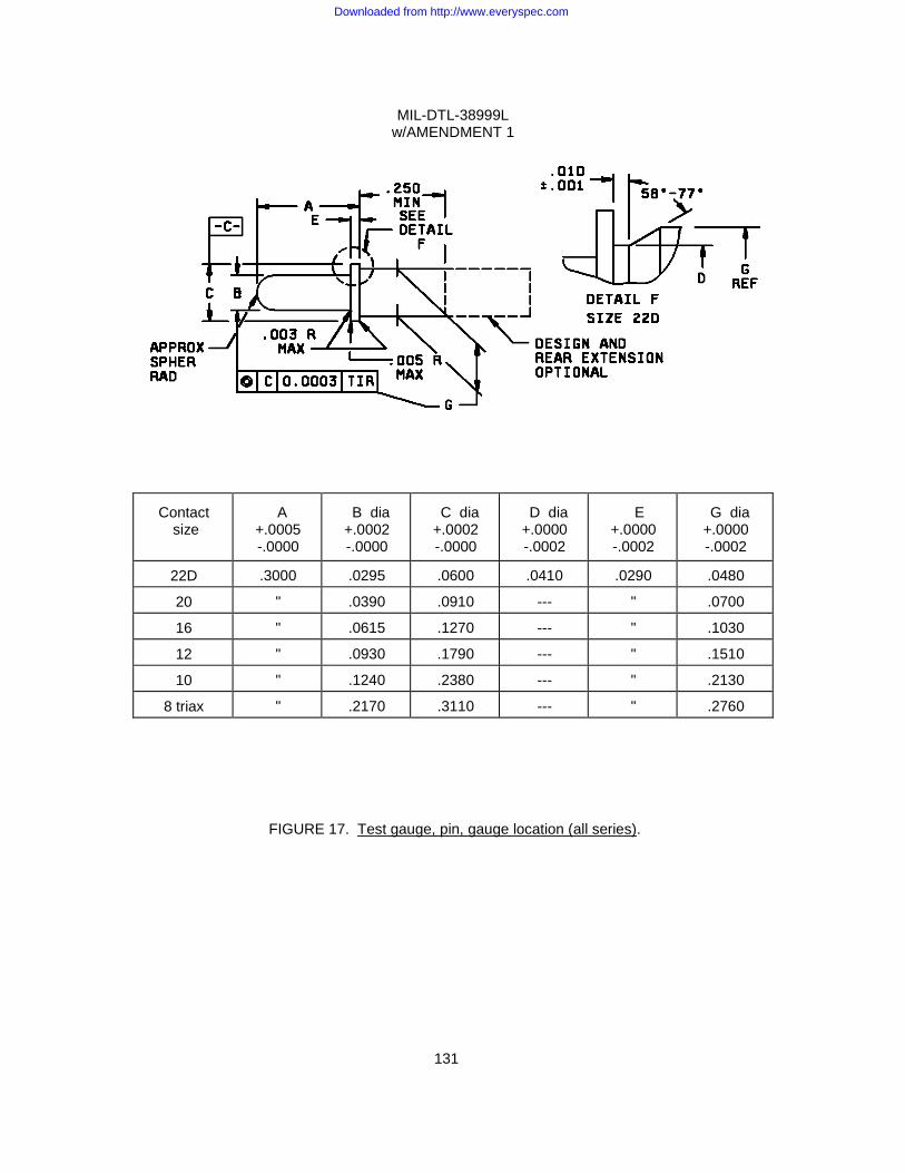
MIL-DTL-38999L w/AMENDMENT 1
131
Contact size
A
+.0005 -.0000
B dia +.0002 -.0000
C dia +.0002 -.0000
D dia +.0000 -.0002
E
+.0000 -.0002
G dia +.0000 -.0002
22D .3000 .0295 .0600 .0410 .0290 .0480
20 " .0390 .0910 --- " .0700
16 " .0615 .1270 --- " .1030
12 " .0930 .1790 --- " .1510
10 " .1240 .2380 --- " .2130
8 triax " .2170 .3110 --- " .2760
FIGURE 17. Test gauge, pin, gauge location (all series).
Downloaded from http://www.everyspec.com
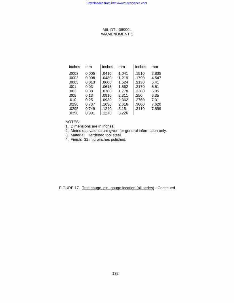
MIL-DTL-38999L w/AMENDMENT 1
132
Inches mm Inches mm Inches mm
.0002
.0003
.0005
.001
.003
.005
.010
.0290
.0295
.0390
0.005 0.008 0.013 0.03 0.08 0.13 0.25 0.737 0.749 0.991
.0410
.0480
.0600
.0615
.0700
.0910
.0930
.1030
.1240
.1270
1.041 1.219 1.524 1.562 1.778 2.311 2.362 2.616 3.15 3.226
.1510
.1790
.2130
.2170
.2380
.250
.2760
.3000
.3110
3.835 4.547 5.41 5.51 6.05 6.35 7.01 7.620 7.899
NOTES: 1. Dimensions are in inches. 2. Metric equivalents are given for general information only. 3. Material: Hardened tool steel. 4. Finish: 32 microinches polished.
FIGURE 17. Test gauge, pin, gauge location (all series) - Continued.
Downloaded from http://www.everyspec.com
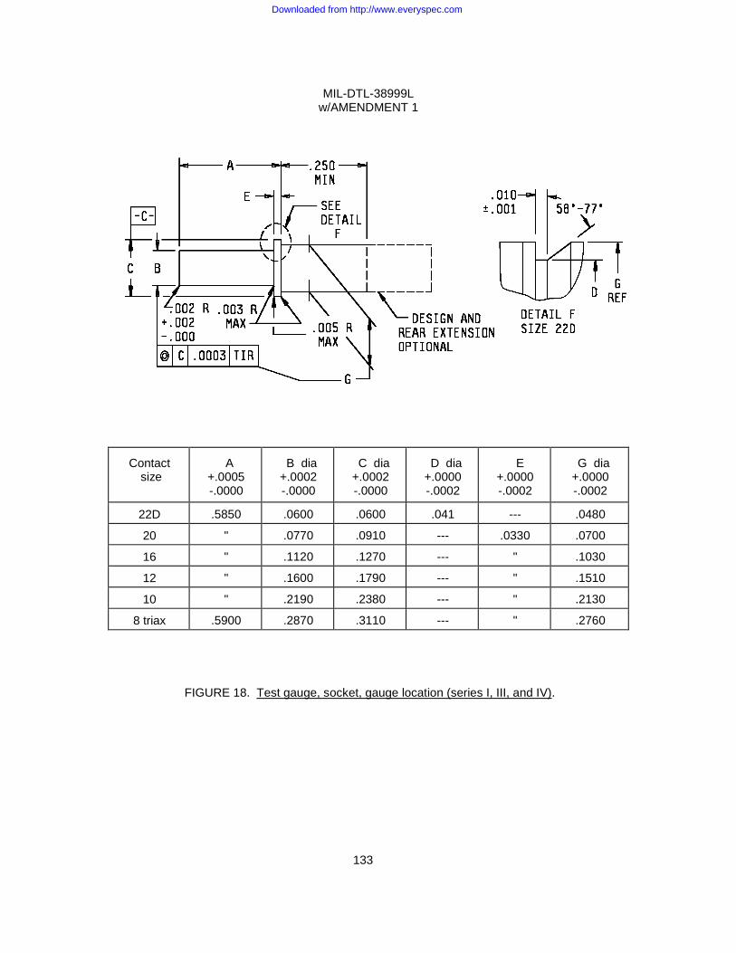
MIL-DTL-38999L w/AMENDMENT 1
133
Contact
size
A
+.0005 -.0000
B dia +.0002 -.0000
C dia +.0002 -.0000
D dia +.0000 -.0002
E
+.0000 -.0002
G dia +.0000 -.0002
22D .5850 .0600 .0600 .041 --- .0480
20 " .0770 .0910 --- .0330 .0700
16 " .1120 .1270 --- " .1030
12 " .1600 .1790 --- " .1510
10 " .2190 .2380 --- " .2130
8 triax .5900 .2870 .3110 --- " .2760
FIGURE 18. Test gauge, socket, gauge location (series I, III, and IV).
Downloaded from http://www.everyspec.com
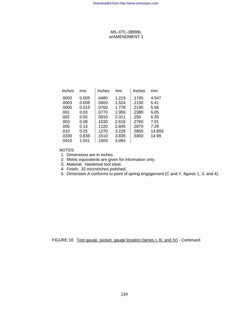
MIL-DTL-38999L w/AMENDMENT 1
134
Inches mm Inches mm Inches mm
.0002
.0003
.0005
.001
.002
.003
.005
.010
.0330
.0410
0.005 0.008 0.013 0.03 0.05 0.08 0.13 0.25 0.838 1.041
.0480
.0600
.0700
.0770
.0910
.1030
.1120
.1270
.1510
.1600
1.219 1.524 1.778 1.956 2.311 2.616 2.845 3.226 3.835 4.064
.1790
.2130
.2190
.2380
.250
.2760
.2870
.5850
.5900
4.547 5.41 5.56 6.05 6.35 7.01 7.29 14.859 14.99
NOTES:
1. Dimensions are in inches. 2. Metric equivalents are given for information only. 3. Material: Hardened tool steel. 4. Finish: 32 microinches polished. 5. Dimension A conforms to point of spring engagement (C and Y, figures 1, 3, and 4).
FIGURE 18. Test gauge, socket, gauge location (series I, III, and IV) - Continued.
Downloaded from http://www.everyspec.com
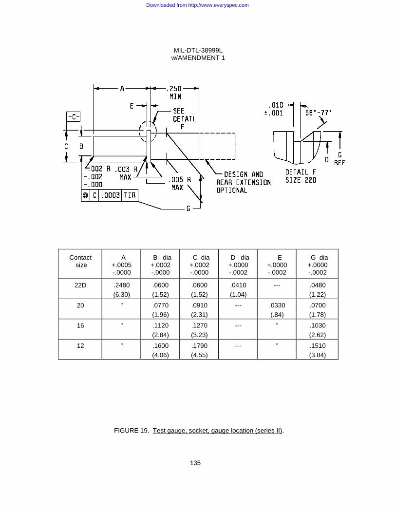
MIL-DTL-38999L w/AMENDMENT 1
135
Contact
size
A
+.0005 -.0000
B dia +.0002 -.0000
C dia +.0002 -.0000
D dia +.0000 -.0002
E
+.0000 -.0002
G dia +.0000 -.0002
22D .2480 (6.30)
.0600 (1.52)
.0600 (1.52)
.0410 (1.04)
--- .0480 (1.22)
20 " .0770 (1.96)
.0910 (2.31)
--- .0330 (.84)
.0700 (1.78)
16 " .1120 (2.84)
.1270 (3.23)
--- " .1030 (2.62)
12 " .1600 (4.06)
.1790 (4.55)
--- " .1510 (3.84)
FIGURE 19. Test gauge, socket, gauge location (series II).
Downloaded from http://www.everyspec.com
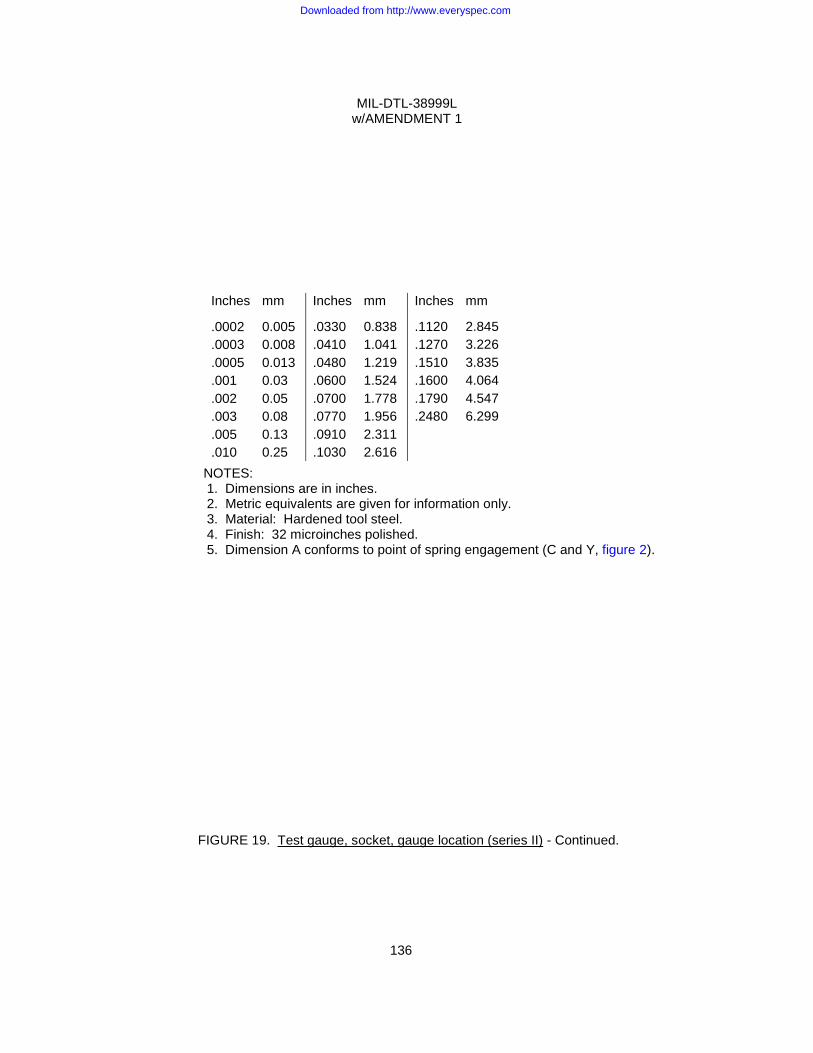
MIL-DTL-38999L w/AMENDMENT 1
136
NOTES: 1. Dimensions are in inches. 2. Metric equivalents are given for information only. 3. Material: Hardened tool steel. 4. Finish: 32 microinches polished. 5. Dimension A conforms to point of spring engagement (C and Y, figure 2).
FIGURE 19. Test gauge, socket, gauge location (series II) - Continued.
Inches mm Inches mm Inches mm
.0002
.0003
.0005
.001
.002
.003
.005
.010
0.005 0.008 0.013 0.03 0.05 0.08 0.13 0.25
.0330
.0410
.0480
.0600
.0700
.0770
.0910
.1030
0.838 1.041 1.219 1.524 1.778 1.956 2.311 2.616
.1120
.1270
.1510
.1600
.1790
.2480
2.845 3.226 3.835 4.064 4.547 6.299
Downloaded from http://www.everyspec.com
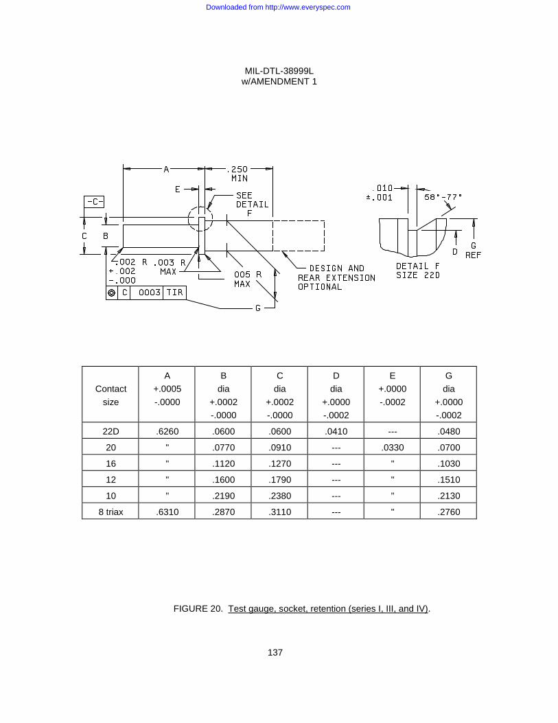
MIL-DTL-38999L w/AMENDMENT 1
137
Contact size
A +.0005 -.0000
B dia
+.0002 -.0000
C dia
+.0002 -.0000
D dia
+.0000 -.0002
E +.0000 -.0002
G dia
+.0000 -.0002
22D .6260 .0600 .0600 .0410 --- .0480
20 " .0770 .0910 --- .0330 .0700
16 " .1120 .1270 --- " .1030
12 " .1600 .1790 --- " .1510
10 " .2190 .2380 --- " .2130
8 triax .6310 .2870 .3110 --- " .2760
FIGURE 20. Test gauge, socket, retention (series I, III, and IV).
Downloaded from http://www.everyspec.com
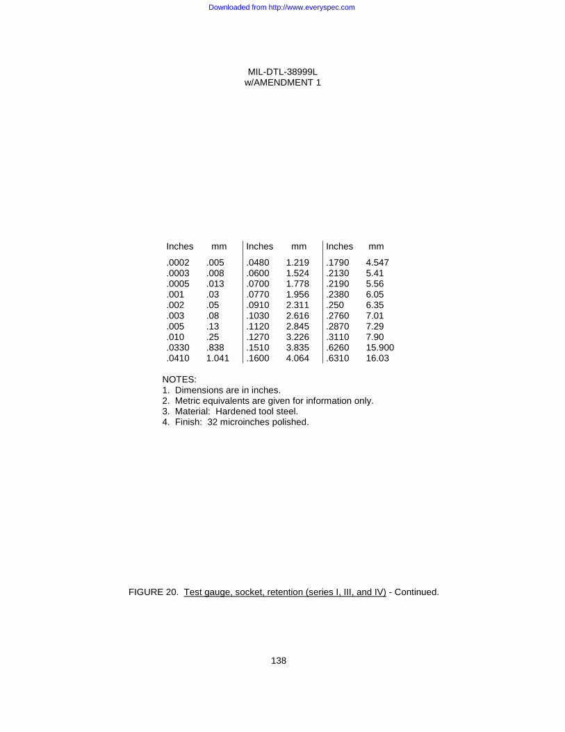
MIL-DTL-38999L w/AMENDMENT 1
138
Inches mm Inches mm Inches mm
.0002
.0003
.0005
.001
.002
.003
.005
.010
.0330
.0410
.005
.008
.013
.03
.05
.08
.13
.25
.838 1.041
.0480
.0600
.0700
.0770
.0910
.1030
.1120
.1270
.1510
.1600
1.219 1.524 1.778 1.956 2.311 2.616 2.845 3.226 3.835 4.064
.1790
.2130
.2190
.2380
.250
.2760
.2870
.3110
.6260
.6310
4.547 5.41 5.56 6.05 6.35 7.01 7.29 7.90 15.900 16.03
NOTES: 1. Dimensions are in inches. 2. Metric equivalents are given for information only. 3. Material: Hardened tool steel. 4. Finish: 32 microinches polished.
FIGURE 20. Test gauge, socket, retention (series I, III, and IV) - Continued.
Downloaded from http://www.everyspec.com
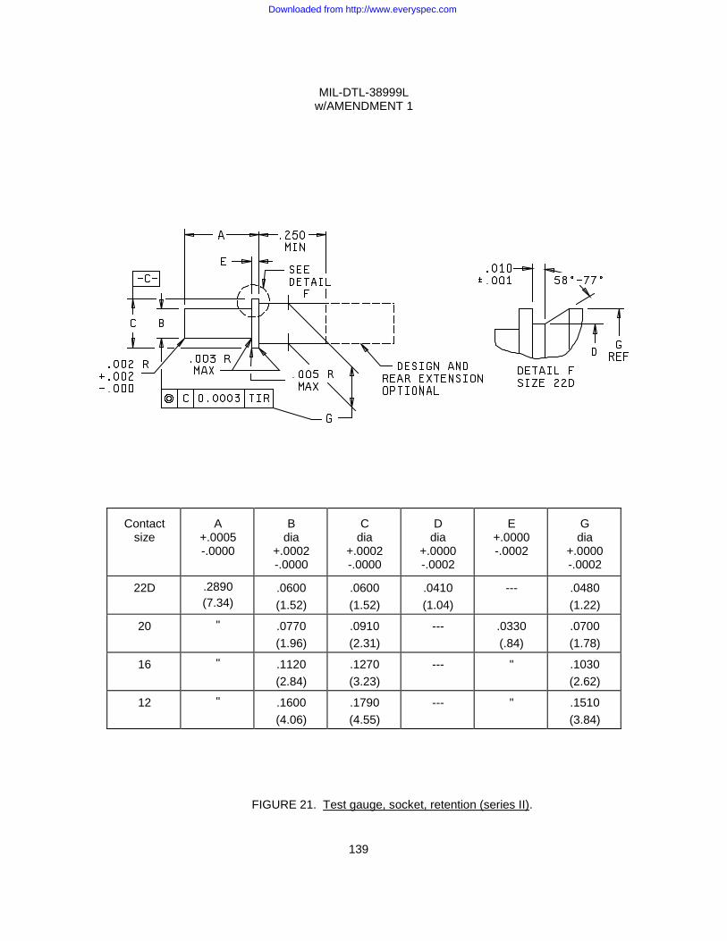
MIL-DTL-38999L w/AMENDMENT 1
139
Contact size
A
+.0005 -.0000
B
dia +.0002 -.0000
C
dia +.0002 -.0000
D
dia +.0000 -.0002
E
+.0000 -.0002
G dia
+.0000 -.0002
22D .2890 (7.34)
.0600 (1.52)
.0600 (1.52)
.0410 (1.04)
--- .0480 (1.22)
20 " .0770 (1.96)
.0910 (2.31)
--- .0330 (.84)
.0700 (1.78)
16 " .1120 (2.84)
.1270 (3.23)
--- " .1030 (2.62)
12 " .1600 (4.06)
.1790 (4.55)
--- " .1510 (3.84)
FIGURE 21. Test gauge, socket, retention (series II).
Downloaded from http://www.everyspec.com
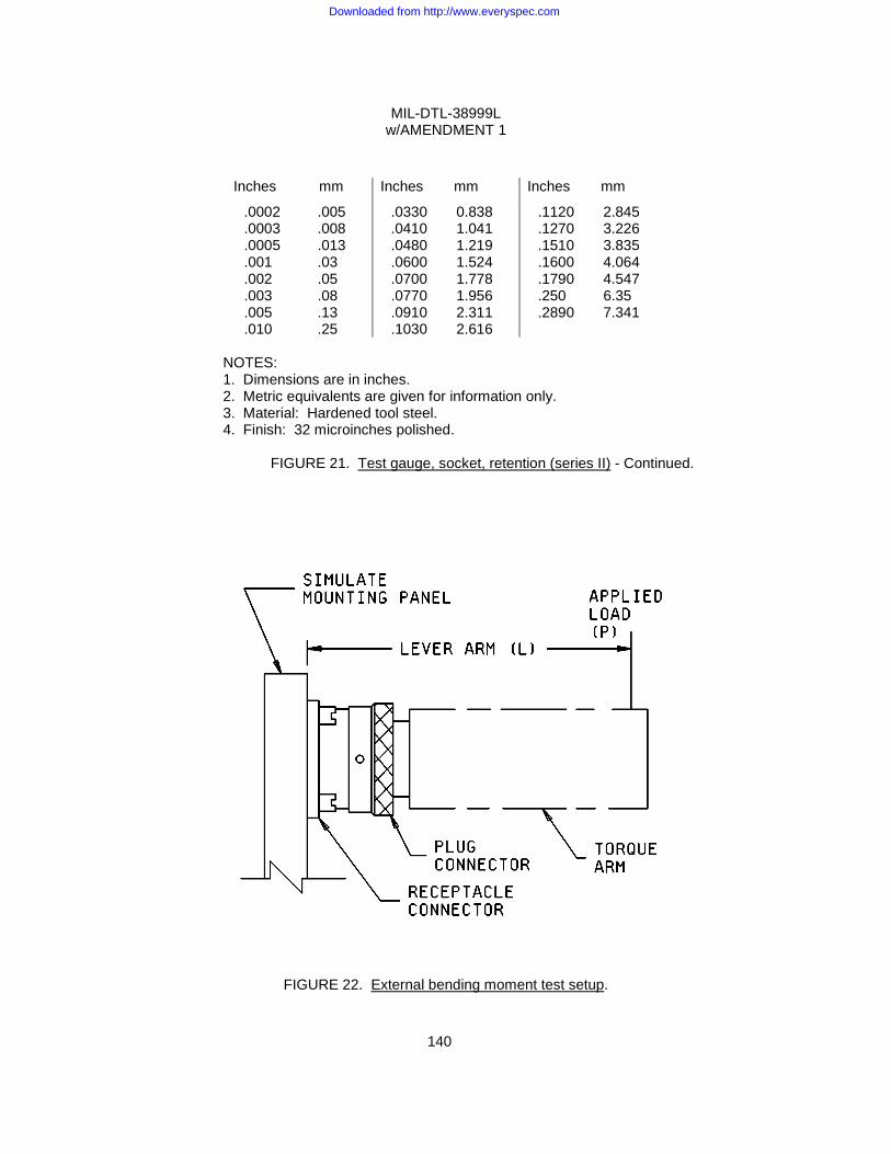
MIL-DTL-38999L w/AMENDMENT 1
140
Inches mm Inches mm Inches mm
.0002
.0003
.0005
.001
.002
.003
.005
.010
.005
.008
.013
.03
.05
.08
.13
.25
.0330
.0410
.0480
.0600
.0700
.0770
.0910
.1030
0.838 1.041 1.219 1.524 1.778 1.956 2.311 2.616
.1120
.1270
.1510
.1600
.1790
.250
.2890
2.845 3.226 3.835 4.064 4.547 6.35 7.341
NOTES: 1. Dimensions are in inches. 2. Metric equivalents are given for information only. 3. Material: Hardened tool steel. 4. Finish: 32 microinches polished.
FIGURE 21. Test gauge, socket, retention (series II) - Continued.
FIGURE 22. External bending moment test setup.
Downloaded from http://www.everyspec.com
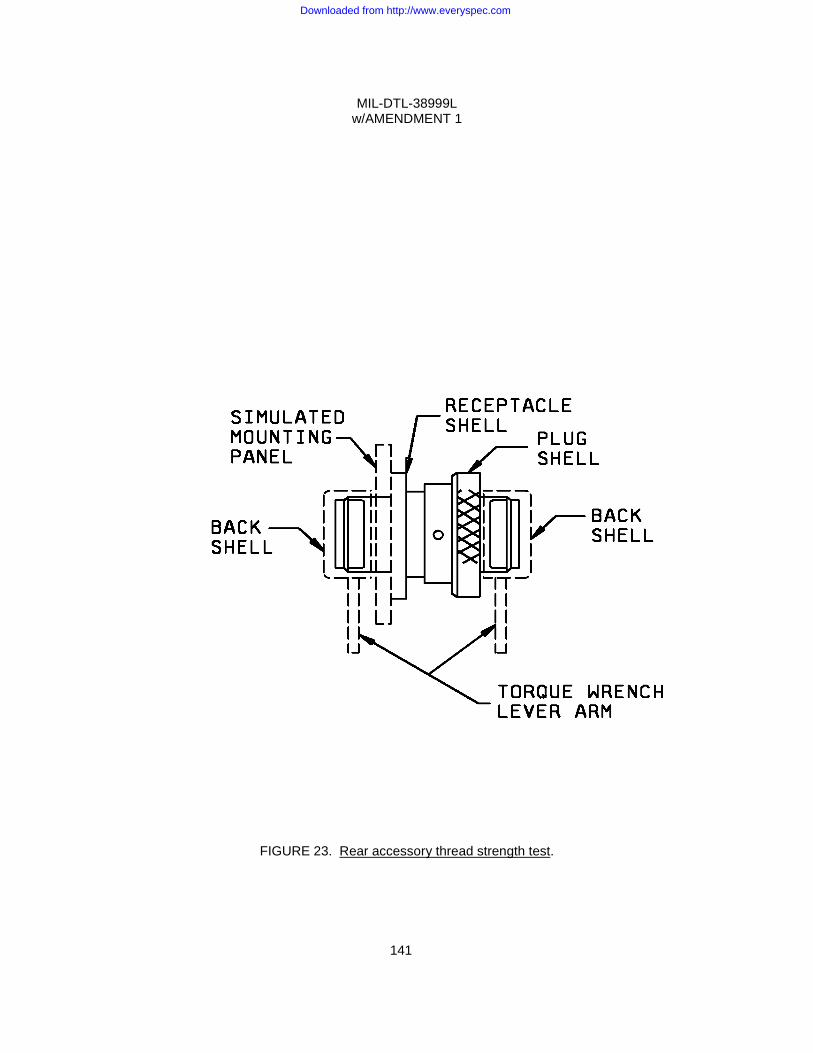
MIL-DTL-38999L w/AMENDMENT 1
141
FIGURE 23. Rear accessory thread strength test.
Downloaded from http://www.everyspec.com
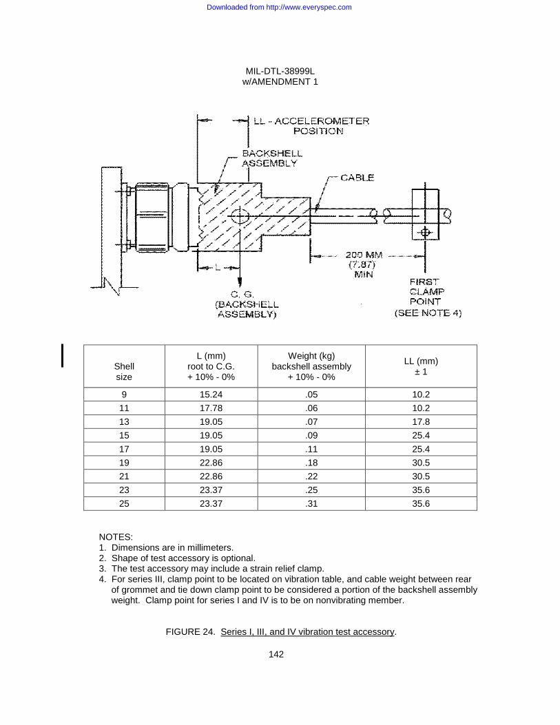
MIL-DTL-38999L w/AMENDMENT 1
142
Shell size
L (mm) root to C.G. + 10% - 0%
Weight (kg) backshell assembly
+ 10% - 0%
LL (mm)
± 1
9 15.24 .05 10.2 11 17.78 .06 10.2 13 19.05 .07 17.8 15 19.05 .09 25.4 17 19.05 .11 25.4 19 22.86 .18 30.5 21 22.86 .22 30.5 23 23.37 .25 35.6 25 23.37 .31 35.6
NOTES: 1. Dimensions are in millimeters. 2. Shape of test accessory is optional. 3. The test accessory may include a strain relief clamp. 4. For series III, clamp point to be located on vibration table, and cable weight between rear
of grommet and tie down clamp point to be considered a portion of the backshell assembly weight. Clamp point for series I and IV is to be on nonvibrating member.
FIGURE 24. Series I, III, and IV vibration test accessory.
Downloaded from http://www.everyspec.com

MIL-DTL-38999L w/AMENDMENT 1
143
FIGURE 25. Random vibration (series I, III and IV).
Downloaded from http://www.everyspec.com
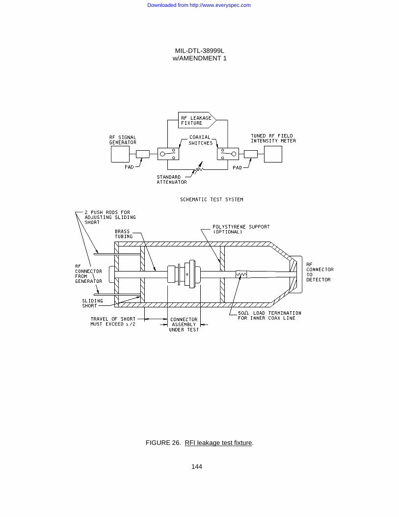
MIL-DTL-38999L w/AMENDMENT 1
144
FIGURE 26. RFI leakage test fixture.
Downloaded from http://www.everyspec.com
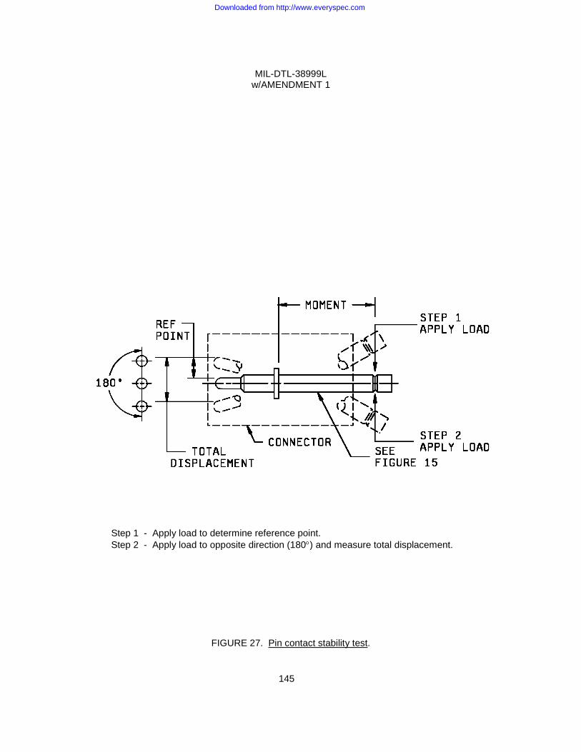
MIL-DTL-38999L w/AMENDMENT 1
145
Step 1 - Apply load to determine reference point. Step 2 - Apply load to opposite direction (180°) and measure total displacement.
FIGURE 27. Pin contact stability test.
Downloaded from http://www.everyspec.com
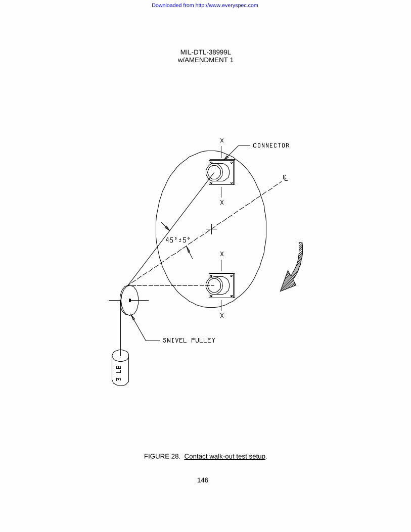
MIL-DTL-38999L w/AMENDMENT 1
146
FIGURE 28. Contact walk-out test setup.
Downloaded from http://www.everyspec.com
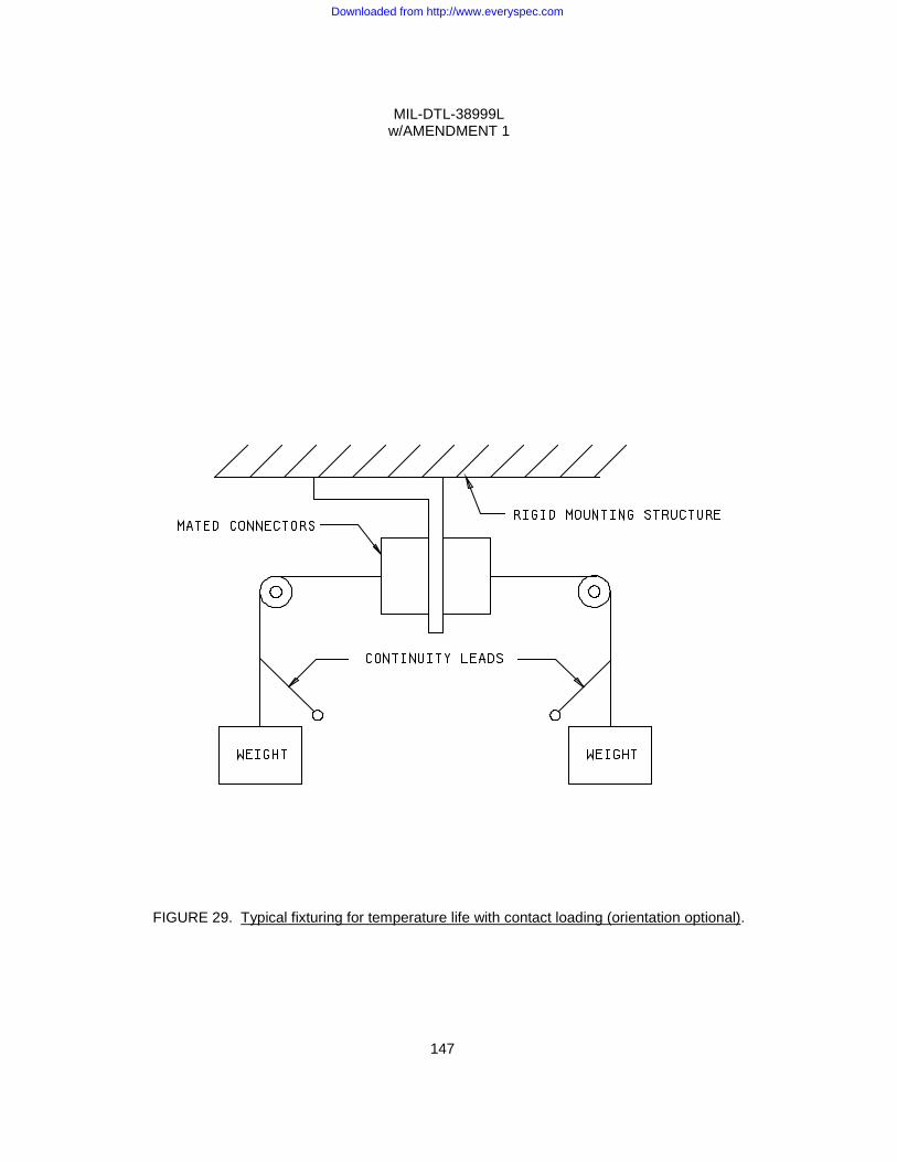
MIL-DTL-38999L w/AMENDMENT 1
147
FIGURE 29. Typical fixturing for temperature life with contact loading (orientation optional).
Downloaded from http://www.everyspec.com
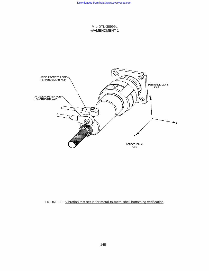
MIL-DTL-38999L w/AMENDMENT 1
148
FIGURE 30. Vibration test setup for metal-to-metal shell bottoming verification.
Downloaded from http://www.everyspec.com
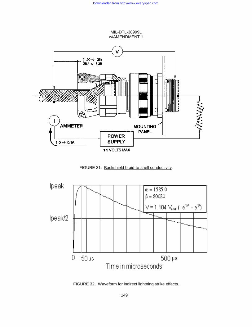
MIL-DTL-38999L w/AMENDMENT 1
149
FIGURE 31. Backshield braid-to-shell conductivity.
FIGURE 32. Waveform for indirect lightning strike effects.
Downloaded from http://www.everyspec.com
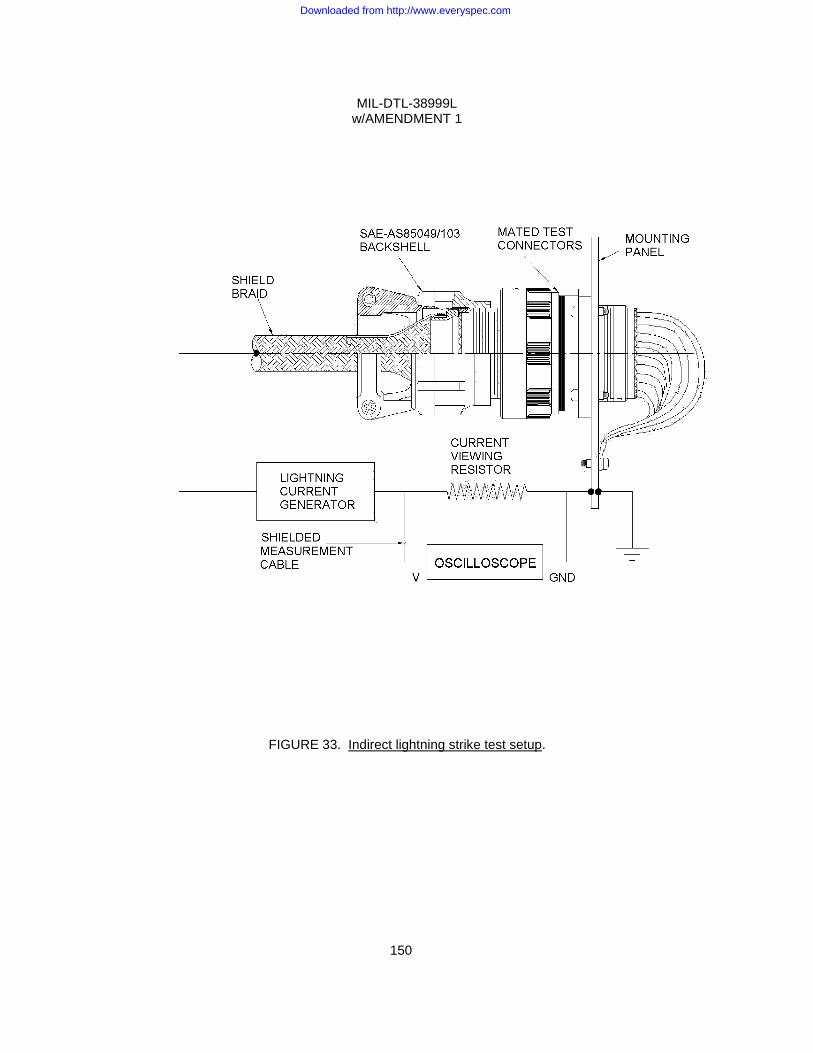
MIL-DTL-38999L w/AMENDMENT 1
150
FIGURE 33. Indirect lightning strike test setup.
Downloaded from http://www.everyspec.com
MIL-DTL-38999L w/AMENDMENT 1
APPENDIX A
151
NICKEL PLATING (ELECTRODEPOSITED)
A.1 SCOPE A.1.1 Scope. This appendix covers the requirements for electrodeposited nickel plating on steel, copper and copper alloys, and zinc and zinc alloys. This Appendix is a mandatory part of the specification. The information contained herein is intended for compliance. A.1.2 Classification. A.1.2.1 Classes. Electrodeposited nickel plating covered by this appendix shall be of the following classes, as specified (see A.6.2): Class 1 - Corrosion protective plating Class 2 - Engineering plating A.1.2.2 Grades. Class 1 plating thickness shall be of the following grades, as specified (see A.6.2): Grade A - 0.0016 inch (0.0406 mm) minimum Grade B - 0.0012 inch (0.0305 mm) minimum Grade C - 0.0010 inch (0.0254 mm) minimum Grade D - 0.0008 inch (0.0203 mm) minimum Grade E - 0.0006 inch (0.0152 mm) minimum Grade F - 0.0004 inch (0.0102 mm) minimum Grade G - 0.0002 inch (0.0051 mm) minimum A.2 APPLICABLE DOCUMENTS A.2.1 General. The documents listed in this section are specified in sections A.3 and A.4 of this specification. This section does not include documents cited in other sections of this specification or recommended for additional information or as examples. While every effort has been made to ensure the completeness of this list, document users are cautioned that they must meet all specified requirements documents cited in sections A.3 and A.4 of this specification, whether or not they are listed. A.2.2 Government documents. A.2.2.1 Specifications, standards, and handbooks. The following specifications, standards, and handbooks form a part of this document to the extent specified herein. Unless otherwise specified, the issues of these documents are those cited in the solicitation or contract (see A.6.2). DEPARTMENT OF DEFENSE SPECIFICATION
MIL-S-5002 - Surface Treatments and Inorganic Coatings for Metal Surfaces of Weapons Systems.
(Copies of these documents are available online at http://assist.daps.dla.mil/quicksearch/ or
from the Standardization Document Order Desk, 700 Robbins Avenue, Building 4D, Philadelphia, PA 19111-5094.)
Downloaded from http://www.everyspec.com
MIL-DTL-38999L w/AMENDMENT 1
APPENDIX A
152
A.2.2.2 Non-Government publications. The following documents form a part of this document to the extent specified herein. Unless otherwise specified, the issues of these documents are those cited in the solicitation or contract (see A.6.2). AMERICAN SOCIETY FOR TESTING AND MATERIALS (ASTM)
ASTM A108 - Standard Specification for Steel Bar, Carbon and Alloy, Cold-Finished. ASTM A304 - Standard Specification for Carbon and Alloy Steel Bars Subject to End-Quench Hardenability Requirements. ASTM A322 - Standard Specification for Steel Bars, Alloy, Standard Grades. ASTM B244 - Standard Test Method for Measurement of Thickness of Anodic Coatings on
Aluminum and of Other Nonconductive Coatings on Nonmagnetic Basis Metals with Eddy-Current Instruments.
ASTM B487 - Measuring Metal and Oxide Coating Thickness by Microscopic Examination of
a Cross Section.
ASTM B504 - Measuring the Thickness of Metallic Coatings by this Coulometric Method. ASTM B530 - Measurement of Coating Thickness by the Magnetic Method:
Electrodeposited Nickel Coatings on Magnetic and Nonmagnetic Substrates.
ASTM E8/E8M - Standard Test Method for Tension Testing of Metallic Materials. (Copies of these documents are available at http://www.astm.org or ASTM International, 100 Barr Harbor Drive, PO Box C700, West Conshohocken, Pennsylvania 19428-2959.) A.3 REQUIREMENTS A.3.1 Materials. The materials used shall be such as to produce platings which meet the requirements of this appendix. A.3.2 General requirements. A.3.2.1 High tensile strength steel parts. Unless otherwise specified, steel parts having an ultimate tensile strength greater than 240,000 pounds per square inch (psi) shall not be plated without specific approval of the procuring activity (see A.6.2). A.3.2.2 Stress relief treatment. Unless otherwise specified, all steel parts which are machined, ground, cold formed or cold straightened, shall be given a heat treatment at a minimum of 375 ± 25°F (191 ± 14°C) for three hours or more prior to cleaning and plating for the relief of damaging residual tensile stresses (see A.6.2 and A.6.4). A.3.2.3 Cleaning. Unless otherwise specified, all steel parts shall be cleaned in accordance with MIL-S-5002 (see A.6.2). Other basis metals shall be cleaned by methods which shall not damage the substrate and shall not interfere with adhesion of the deposit (see A.6.5).
Downloaded from http://www.everyspec.com
MIL-DTL-38999L w/AMENDMENT 1
APPENDIX A
153
A.3.2.4 Plating application. Unless otherwise specified, the plating shall be applied after all basis metal heat treatments and mechanical operations such as machining, brazing, welding, forming and perforating of the article have been completed (see A.6.2). A.3.2.5 Underplating. When specified in the contract, purchase order or applicable drawing (see A.6.2), class 1 plating shall be applied over a plating of copper on steel, copper and copper based alloys. Class 1 plating shall be applied over an underplating of copper or yellow brass on zinc and zinc based alloys. In no case, shall the copper underplate (see A.3.3.1.1.2 and table A-I) be substituted for any part of the specified nickel thickness. A.3.2.6 Class 1 processing. Parts for class 1 deposition shall be plated to specific dimensions as specified (see A.3.3.1.1). When specified, parts shall be processed in accordance with procedural instructions for form of nickel deposit (see A.6.2 and A.6.7). A.3.2.7 Class 2 processing. Parts for class 2 deposition shall be plated to specific dimensions as specified (see A.3.3.1.2). When specified, parts shall be processed in accordance with procedural instructions of the procuring activity (see A.6.2). A.3.2.8 Coverage. Unless otherwise specified, the plating shall cover all surfaces including roots of threads, corners and recesses (see A.6.2). A.3.2.9 Boundaries. Boundaries of class 2 plating which cover only a portion of the surface shall be free from beads, nodules, jagged edges and other irregularities. A.3.2.10 Surface finish. Unless otherwise specified, either a fully bright or dull (semi-bright finish shall be acceptable (see A.6.2 and A.6.7)). A.3.2.11 Embrittlement relief. All steel parts having a hardness of Rockwell C40 and higher shall be baked at a minimum of 375 ± 25°F (191 ± 14°C) for three hours or more, within four hours after plating, to provide hydrogen embrittlement relief (see A.6.6). The baked parts, when tested in accordance with A.4.5.3, shall not crack or fail by fracture (see A.4.4.3.3). Plated springs and other parts subject to flexure shall not be flexed prior to the hydrogen embrittlement relief treatment. A.3.3 Detail requirements. A.3.3.1 Thickness of plating. A.3.3.1.1 Class 1. Unless otherwise specified, the minimum thickness of class 1 nickel plating shall be as specified in table A-I on all visible surfaces which can be touched by a ball 0.75 inch (19 mm) in diameter. All other surfaces which cannot be touched by the 0.75 inch (19 mm) diameter ball shall not be less than the minimum thickness specified in table A-I. A.3.3.1.1.1 Unless otherwise specified, the minimum nickel plating for ferrous materials or for zinc and zinc base alloys shall be grade C. Unless otherwise specified, the minimum nickel plating for copper and copper alloys shall be grade D. If the maximum thickness for grade A is not specified in the contract, order or applicable drawing, the thickness shall not exceed 0.0020 inch (51 micrometers) on all visible surfaces which can be touched by the 0.75 inch (19 mm) diameter ball.
Downloaded from http://www.everyspec.com
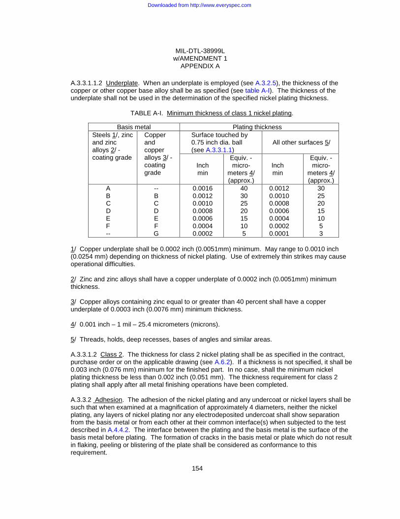
MIL-DTL-38999L w/AMENDMENT 1
APPENDIX A
154
A.3.3.1.1.2 Underplate. When an underplate is employed (see A.3.2.5), the thickness of the copper or other copper base alloy shall be as specified (see table A-I). The thickness of the underplate shall not be used in the determination of the specified nickel plating thickness.
TABLE A-I. Minimum thickness of class 1 nickel plating.
Basis metal Plating thickness Steels 1/, zinc and zinc alloys 2/ - coating grade
Copper and copper alloys 3/ - coating grade
Surface touched by 0.75 inch dia. ball (see A.3.3.1.1)
All other surfaces 5/
Inch min
Equiv. -micro-
meters 4/ (approx.)
Inch min
Equiv. -micro-
meters 4/ (approx.)
A B C D E F --
-- B C D E F G
0.0016 0.0012 0.0010 0.0008 0.0006 0.0004 0.0002
40 30 25 20 15 10 5
0.0012 0.0010 0.0008 0.0006 0.0004 0.0002 0.0001
30 25 20 15 10 5 3
1/ Copper underplate shall be 0.0002 inch (0.0051mm) minimum. May range to 0.0010 inch (0.0254 mm) depending on thickness of nickel plating. Use of extremely thin strikes may cause operational difficulties. 2/ Zinc and zinc alloys shall have a copper underplate of 0.0002 inch (0.0051mm) minimum thickness. 3/ Copper alloys containing zinc equal to or greater than 40 percent shall have a copper underplate of 0.0003 inch (0.0076 mm) minimum thickness. 4/ 0.001 inch – 1 mil – 25.4 micrometers (microns). 5/ Threads, holds, deep recesses, bases of angles and similar areas. A.3.3.1.2 Class 2. The thickness for class 2 nickel plating shall be as specified in the contract, purchase order or on the applicable drawing (see A.6.2). If a thickness is not specified, it shall be 0.003 inch (0.076 mm) minimum for the finished part. In no case, shall the minimum nickel plating thickness be less than 0.002 inch (0.051 mm). The thickness requirement for class 2 plating shall apply after all metal finishing operations have been completed. A.3.3.2 Adhesion. The adhesion of the nickel plating and any undercoat or nickel layers shall be such that when examined at a magnification of approximately 4 diameters, neither the nickel plating, any layers of nickel plating nor any electrodeposited undercoat shall show separation from the basis metal or from each other at their common interface(s) when subjected to the test described in A.4.4.2. The interface between the plating and the basis metal is the surface of the basis metal before plating. The formation of cracks in the basis metal or plate which do not result in flaking, peeling or blistering of the plate shall be considered as conformance to this requirement.
Downloaded from http://www.everyspec.com
MIL-DTL-38999L w/AMENDMENT 1
APPENDIX A
155
A.3.4 Workmanship. A.3.4.1 Basis metal. The basis metal shall be free from visible defects that will be detrimental to the appearance or protective value of the plating. The basis metal shall be subject to such cleaning and plating procedures as necessary to yield deposits herein specified. A.3.4.2 Plating. The nickel plating shall be smooth, fine grained, adherent, uniform in appearance, free from blisters, pits, nodules, excessive edge build-up and other defects. The plating shall show no indication or contamination or improper operation of equipment used to produce the nickel deposit, such as excessively powdered or darkened platings, build-up and other defects. The size and number of contact marks shall be at a minimum consistent with good practice. The location of contact marks shall be in areas of minimum exposure to service environmental conditions where important to the function of the part. Superficial staining which has been demonstrated as resulting from rinsing, or slight discoloration resulting from baking operations to relieve embrittlement, as specified above (see A.3.2.11), shall not be cause for rejection. All details of workmanship shall conform to the best practice for high quality plating. A.4 VERIFICATION A.4.1 Classification of inspection. The inspection requirements specified herein are classified as follows: 1 – Production control inspection (see A.4.2). 2 – Conformance inspection (see A.4.3). A.4.2 Production control inspection. A.4.2.1 Control records. When specified in the contract or order (see A.6.2), the supplier shall maintain a record of each processing bath, showing all additional chemicals or treatment solutions to the unit, the results of all analyses performed and the quantity of parts plated during operation. Upon request of the procuring activity, such records shall be made available. These records shall be maintained for not less than one year after completion of the contract or purchase order. A.4.2.2 Production control. The equipment, procedures and operations employed by a supplier shall be capable of producing high quality electrodeposited platings of nickel on ferrous alloys, copper and copper alloys, zinc and zinc alloys as specified in this document. When specified by the procuring activity (see A.6.2), the supplier, prior to production, shall demonstrate the capability of the process used to show freedom from hydrogen embrittlement damage as specified by satisfactory behavior of specimens prepared (see A.6.2.2) and tested in accordance with A.4.2.2.1 to comply to the requirements of MIL-S-5002 for preproduction process qualification. A.4.2.2.1 Preproduction control. For preproduction control four round notched steel specimens shall be prepared in accordance with A.4.3.4.2 from four individual heats for a total of 16 specimens, using the specified steel alloys for which preproduction examination of the process is to be demonstrated. Specimens shall be heat treated to the maximum tensile strength representing production usage. The specimens shall be given the same pre-treatments, proposed for production. The specimens shall be subject to testing as specified in A.4.4.3. The process shall be considered satisfactory if all specimens show no indication of cracks or failure. The test results and production control information shall be submitted to the procuring activity for approval. Until approval has been received, parts shall not be plated.
Downloaded from http://www.everyspec.com
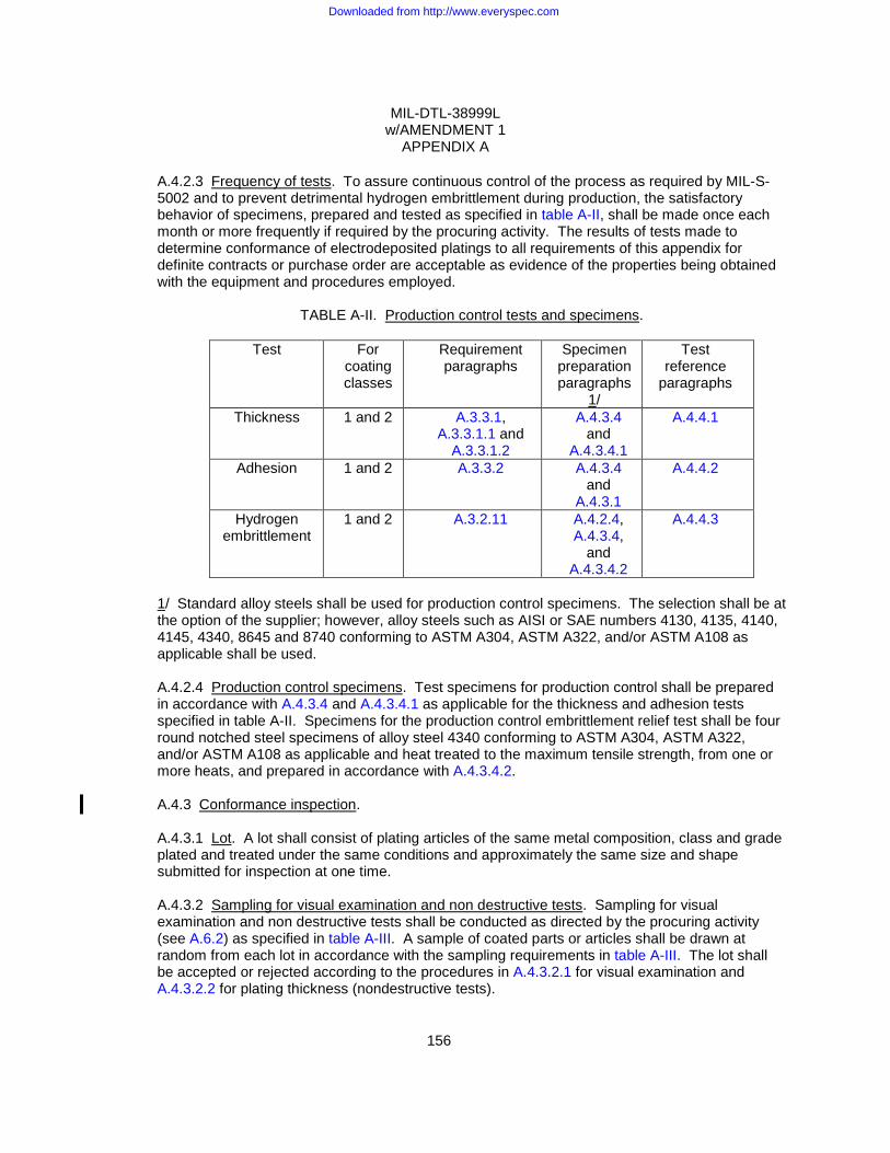
MIL-DTL-38999L w/AMENDMENT 1
APPENDIX A
156
A.4.2.3 Frequency of tests. To assure continuous control of the process as required by MIL-S-5002 and to prevent detrimental hydrogen embrittlement during production, the satisfactory behavior of specimens, prepared and tested as specified in table A-II, shall be made once each month or more frequently if required by the procuring activity. The results of tests made to determine conformance of electrodeposited platings to all requirements of this appendix for definite contracts or purchase order are acceptable as evidence of the properties being obtained with the equipment and procedures employed.
TABLE A-II. Production control tests and specimens.
Test For coating classes
Requirement paragraphs
Specimen preparation paragraphs
1/
Test reference
paragraphs
Thickness 1 and 2 A.3.3.1, A.3.3.1.1 and
A.3.3.1.2
A.4.3.4 and
A.4.3.4.1
A.4.4.1
Adhesion 1 and 2 A.3.3.2 A.4.3.4 and
A.4.3.1
A.4.4.2
Hydrogen embrittlement
1 and 2 A.3.2.11 A.4.2.4, A.4.3.4,
and A.4.3.4.2
A.4.4.3
1/ Standard alloy steels shall be used for production control specimens. The selection shall be at the option of the supplier; however, alloy steels such as AISI or SAE numbers 4130, 4135, 4140, 4145, 4340, 8645 and 8740 conforming to ASTM A304, ASTM A322, and/or ASTM A108 as applicable shall be used. A.4.2.4 Production control specimens. Test specimens for production control shall be prepared in accordance with A.4.3.4 and A.4.3.4.1 as applicable for the thickness and adhesion tests specified in table A-II. Specimens for the production control embrittlement relief test shall be four round notched steel specimens of alloy steel 4340 conforming to ASTM A304, ASTM A322, and/or ASTM A108 as applicable and heat treated to the maximum tensile strength, from one or more heats, and prepared in accordance with A.4.3.4.2. A.4.3 Conformance inspection. A.4.3.1 Lot. A lot shall consist of plating articles of the same metal composition, class and grade plated and treated under the same conditions and approximately the same size and shape submitted for inspection at one time. A.4.3.2 Sampling for visual examination and non destructive tests. Sampling for visual examination and non destructive tests shall be conducted as directed by the procuring activity (see A.6.2) as specified in table A-III. A sample of coated parts or articles shall be drawn at random from each lot in accordance with the sampling requirements in table A-III. The lot shall be accepted or rejected according to the procedures in A.4.3.2.1 for visual examination and A.4.3.2.2 for plating thickness (nondestructive tests).
Downloaded from http://www.everyspec.com

MIL-DTL-38999L w/AMENDMENT 1
APPENDIX A
157
TABLE A-III. Sampling for visual examination and nondestructive tests.
Numbers of items in lot inspections
Number of items in samples (randomly selected)
Acceptance number (maximum number of sample items nonconforming to any
test) 15 or less 16 to 40 41 to 110 111 to 300 301 to 500 501 and over
7 1/ 10 15 25 35 50
0 0 0 1 1 2
1/ If the number of items in the inspection lot is less than 7, the number of items in the sample shall equal the number of items in the inspection lot. A.4.3.2.1 Visual examination. Samples selected in accordance with A.4.3.2 shall be examined for compliance with the requirements specified in A.3.4.2 after plating. If the number of non conforming articles exceeds the acceptance number for the sample, the lot represented by the sample shall be rejected. A.4.3.2.2 Thickness of plating (nondestructive tests). Samples selected in accordance with A.4.3.2 shall be inspected and the plating thickness measured by the applicable tests specified in A.4.4.1, at several locations on each article as specified in A.3.3.1, A.3.3.1.1 or A.3.3.1.2, as applicable, for compliance with the requirements. The part of article shall be considered nonconforming if one or more measurements fail to meet the specified minimum thickness. If the number of defective items in any sample exceeds the acceptance number for the specified sample, the lot represented by the sample shall be rejected. Separate specimens (see A.4.3.4.1) shall not be used for thickness measurements unless a need has been demonstrated. A.4.3.3 Sampling for destructive tests. A random sample of four plated parts or articles shall be taken from each lot for each destructive test or separately plated specimens shall be prepared in accordance with A.4.3.4, A.4.3.4.1 and A.4.3.4.2 to represent each lot. If the number of articles in the lot is four or less, the number of articles in the sample shall be specified by the procuring activity (see A.6.2). A.4.3.3.1 Thickness of plating (destructive tests). If sampling and testing for thickness of plating by nondestructive testing is not the option of the supplier, samples selected in accordance with A.4.3.3 shall be measured for plating thickness by the applicable tests specified in A.4.4.1 at several locations as specified in A.3.3.1, A.3.3.1.1 or A.3.3.1.2, for compliance with the requirements. If the plating thickness at any place on any article or specimen is less than the specified minimum thickness, the lot shall be rejected. Separate specimens (see A.4.3.4.1) shall not be used for thickness measurements unless a need has been demonstrated. A.4.3.3.2 Adhesion (destructive tests). The articles or specimens used for the destructive thickness test (see A.4.3.3.1), if of suitable size and form, may be used as the test pieces for the adhesion test to determine compliance with the requirements of A.3.3.2. Failure of one or more of the test pieces shall constitute failure of the lot.
Downloaded from http://www.everyspec.com
MIL-DTL-38999L w/AMENDMENT 1
APPENDIX A
158
A.4.3.3.3 Hydrogen embrittlement relief (destructive tests). Unless otherwise specified in the contract or order, conformance to the requirements of A.3.2.11 for hydrogen embrittlement relief of treated steel parts shall be determined for those parts having a tensile strength of or heat treated to a tensile strength level of 240,000 psi or above and which will be subject to a sustained tensile load in use (see A.6.2). A random sample of four plated articles shall be taken from each lot or four specimens, prepared in accordance with A.4.3.4 and A.4.3.4.2, shall be used to represent the lot. When tested as specified in A.4.4.3, cracks or failure by fracture shall be cause for rejection. Failure of one or more of the test pieces shall reject the lot. A.4.3.4 Conformance specimen preparation. When the plated articles are of such form, shape, size and value as to prohibit use thereof, or are not readily adaptable to a test specified herein, or when destructive tests of small lot sizes are required the test shall be made by the use of separate specimens plated concurrently with the articles represented. The separate specimens shall be of a basis metal equivalent to that of the articles represented. “Equivalent” basis metal includes chemical composition, grade, condition and finish of surface prior to plating. For example, a cold-rolled steel surface should not be used to represent a hot-rolled steel surface. Due to the impracticality of forging or casting separate test specimens, hot-rolled steel specimens may be used to represent forged and cast-steel articles. The separate specimens may be also cut from scrap castings when ferrous alloy castings are being plated. These separate specimens shall be introduced into a lot at regular intervals prior to the cleaning operations, preliminary to plating, and shall not be separated therefrom until after completion of plating. Conditions affecting the plating of specimens including the spacing, plating media, residual air pressure, temperature, etc. in respect to other objects being plated shall correspond as nearly as possible to those affecting the significant surfaces of the articles represented. Separate specimens shall not be used for thickness measurements, however, unless the necessity for their use has been demonstrated. A.4.3.4.1 Specimens for thickness and adhesion tests. If separate specimens for thickness and adhesion tests are required, they shall be strips approximately 1 inch (25.4 mm) wide, 4 inches (101.6 mm) long and 0.04 inch (1.02 mm) thick. A.4.3.4.2 Specimens for embrittlement relief. Separate specimens for embrittlement relief testing shall be round notched specimens with the axis of the specimen (load direction) perpendicular to the short transverse grain flow direction. The configuration shall be in accordance with ASTM E8/E8M for rounded specimens. Specimens shall have a 60 degree V-notch located approximately at the center of the gage length. The cross section area at the root of the vee shall be approximately equal to half the area of the full cross section area of the specimen’s reduced section. The vee shall have a 0.010 ± 0.0005 inch (0.254 ± 0.0127mm) radius of curvature at the base of the notch (see A.6.2.2). A.4.4 Tests. A.4.4.1 Thickness. For nondestructive measuring of plating thickness, procedures in accordance with ASTM B244 (eddy current), or ASTM B530 (magnetic test) may be used. For destructive measuring of plating thickness, procedures in accordance with ASTM B487 (microscopic) or ASTM B504 (coulometric) may be used. At the option of the supplier other instruments, such as those employing the principle of beta-radiation back scatter or X-ray spectrometry may be used. A.4.4.2 Adhesion. Adhesion may be determined by scraping the surface or shearing with a sharp edge, knife, or razor through the plating down to the basis metal and examining at four
Downloaded from http://www.everyspec.com

MIL-DTL-38999L w/AMENDMENT 1
APPENDIX A
159
diameters magnification for evidence of non-adhesion. Alternately the article or specimen may be clamped in a vise and the projecting portion bent back and forth until rupture occurs. If the edge of the ruptured plating can be peeled back or if separation between the plating and the basis metal can be seen at the point of rupture when examined at four diameters magnification, adhesion is not satisfactory. A.4.4.3 Embrittlement relief. Compliance with A.3.2.11 shall be determined with samples of plated parts taken as specified in A.4.3.3.3. Parts such as spring pins, lock rings, etc., which are installed in holes or rods shall be similarly assembled using the applicable parts specifications or drawing tolerances which impose the maximum sustained tensile load on the plated part. The selected samples shall be subjected to a sustained tensile load equal to 115 percent of the maximum design yield load for which the part was designed. Parts which require special fixtures, extreme loads to comply with the above requirements, or where the maximum design yield load is not known, may be represented by separate specimens prepared in accordance with A.4.3.4.2. The notched specimens shall be subject to a sustained tensile load equal to 75 percent of the ultimate notch tensile strength of the material. The articles, parts or specimens shall be held under load for at least 200 hours and then examined for cracks or fracture. A.5. PREPARATION FOR DELIVERY A.5.1 Packaging and packing. Preservation, packaging and packing methods for electrodeposited nickel plated parts or articles employed by a supplier shall be such as to preclude damaging during shipment and handling. A.6. NOTES A.6.1 Intended use. A.6.1.1 Class 1 plating. Class 1 plating is used to protect iron, copper, or zinc alloys against corrosive attack in rural, industrial or marine atmospheres depending upon the thickness of the nickel deposit or is used as an undercoat for chromium or one of the precious metals. Class 1 plating is also used for decorative purposes. A.6.1.2 Class 2 plating. Class 2 plating is used for wear resistance, abrasion resistance and such incidental corrosion protection of parts as the specified thickness of the nickel plating may afford. Heavy deposits of the class 2 plating, especially when the Watts bath process is employed, may be used for build up of worn or undersized parts, or for salvage purposes, and to provide protection against corrosive chemical environments. A.6.2 Ordering data. Purchasers should select the preferred options permitted herein and include the following information in procurement documents: (a) Title, number, and date of this appendix. (b) Class of plating (see A.1.2.1). (c) Grade of class 1 plating if applicable (see A.1.2.2). (d) When plating is to be applied, if other than specified (see A.3.2.1, A.3.2.4, A.3.2.6
and A.3.2.7).
Downloaded from http://www.everyspec.com
MIL-DTL-38999L w/AMENDMENT 1
APPENDIX A
160
(e) Stress relief treatment, if other than specified (see A.3.2.2). (f) Cleaning of steel, if other than specified (see A.3.2.3). (g) Underplating required (see A.3.2.5). (h) Coverage, if other than specified (see A.3.2.8). (i) Surface finish, if particular finish required (see A.3.2.10). (j) Thickness of coating, if other than specified (see A.3.3.1, A.3.3.1.1, A.3.3.1.1.1 and
A.3.3.1.2). (k) Control record requirement (see A.4.2.1). (l) Preproduction control examination (see A.4.2.2). (m) Sampling plan (see A.4.2.2). (n) Number of samples for destructive testing (see A.4.2.3). (o) Whether hydrogen embrittlement relief test is required (see A.4.3.3.3). A.6.2.1 Basis metal parts. The manufacturer of the basis metal parts should provide the plating facility with the following data: (a) Hardness of steel parts (see A.3.2.1). (b) Heat treatment for stress relief, whether has been performed or is required (see
A.3.2.2). (c) Tensile loads required for embrittlement relief test, if applicable (see A.4.4.3). A.6.2.2 Tensile specimens. The manufacturer of the basis metal parts should provide the plating facility with notched tensile specimens (see A.4.3.4.2) to be plated for conformance with A.3.2.11 required for production control (see A.4.2.2.1, and A.4.2.4) and lot acceptance (see A.4.3.3 and A.4.3.3.3). A.6.3 Black nickel plating. Electrodeposited black nickel plating, in accordance with MIL-P-18317, has little protective value and is used primarily to obtain a dark, nonreflective, decorative finish on steel and copper alloy instrument parts. A.6.4 Stress relief. There is a hazard that hardened and tempered cold-worked or cold-straightened steel parts may crack during cleaning and plating. Such parts should have a suitable heat treatment for stress relief prior to cleaning and plating (see A.3.2.2). A.6.5 Cleaning. Copper and copper-based alloys may be cleaned as specified in ASTM B281, Standard Practice for Preparation of Copper and Copper-Base Alloys for Electroplating and Conversion Coatings. Zinc and zinc-based alloys may be cleaned as specified in ASTM B252, Standard Guide for Preparation of Zinc Alloy Die Castings for Electroplating and Conversion Coating (see A.3.2.3).
Downloaded from http://www.everyspec.com

MIL-DTL-38999L w/AMENDMENT 1
APPENDIX A
161
A.6.6 Baking time. For high strength materials (Rockwell C40 and above), it may be beneficial to extend the baking time to 23 hours to ensure complete hydrogen embrittlement relief (see A.3.2.11). A.6.7 Class 1 processing. Class 1 plating may be processed for the following forms of nickel deposition: SB - Single layer coating in a fully bright finish.
SD - Single layer coating in a dull or semi-bright finish, containing less than 0.005 percent sulfur and having an elongation greater than 8 percent. A full brightness finish may be obtained by polishing the coating. M - Multilayer coating, either double-layer or triple layer. The bottom layer should contain less than 0.005 percent sulfur and have an elongation greater than 8 percent. The top layer should contain more than 0.04 percent sulfur. In a double-layer coating, the thickness of the bottom layer should be not less than 60 percent of the total nickel thickness, except on ferrous parts where the bottom thickness should be not less than 75 percent of the total nickel thickness. In a triple-layer coating, the thickness of the bottom layer should be not less than 50 percent of the total nickel thickness. The intermediate layer of the triple-layer coating should contain more sulfur than the top layer and the thickness should be not greater than 10 percent of the total nickel thickness. The thickness of the top layer of either double- or triple-layer coating should be not less than 10 percent of the total nickel thickness.
A.6.7.1 Correlation. The correlation between the grades of nickel plating used in this appendix and the forms of nickel deposition are specified in table A-IV. A.6.7.2 Thickness measurements. Thickness measurements for the single layer class 1 plating should be made whenever applicable by the non destructive test methods, especially the magnetic method. Thickness measurements for the double or triple layer class 1 plating, should be made on cross sections taken perpendicular to the significant surfaces by the microscopic method. This permits measurements of the thickness of the individual nickel layers when suitable etchants are used. Suitable etchants are as follows: (a) Etchant No. 1. Nitric acid (sp. Gr. 1.42) 1 volume Glacial acetic acid 1 volume (b) Etchant No. 2. Sodium cyanide 100 grams per liter of water Sodium or ammonium persulfate 100 grams per liter of water NOTE: Equal parts of the two water solutions (the cyanide and the persulfate) are mixed. Caution must be taken as toxic fumes are evolved when these solutions of the chemicals are mixed. Use of this etchant must be confined to a well ventilated hood.
Downloaded from http://www.everyspec.com
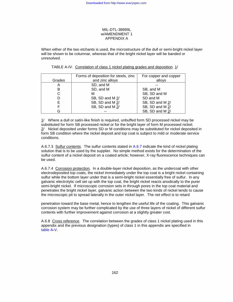
MIL-DTL-38999L w/AMENDMENT 1
APPENDIX A
162
When either of the two etchants is used, the microstructure of the dull or semi-bright nickel layer will be shown to be columnar, whereas that of the bright nickel layer will be banded or unresolved. TABLE A-IV. Correlation of class 1 nickel plating grades and deposition. 1/
Grades Forms of deposition for steels, zinc
and zinc alloys For copper and copper
alloys A B C D E F G
SD, and M SD, and M M
SB, SD and M 2/ SB, SD and M 2/ SB, SD and M 2/
--
-- SB, and M SB, SD and M SD and M
SB, SD and M 2/ SB, SD and M 2/ SB, SD and M 2/
1/ Where a dull or satin-like finish is required, unbuffed form SD processed nickel may be substituted for form SB processed nickel or for the bright layer of form M processed nickel. 2/ Nickel deposited under forms SD or M conditions may be substituted for nickel deposited in form SB condition where the nickel deposit and top coat is subject to mild or moderate service conditions. A.6.7.3 Sulfur contents. The sulfur contents stated in A.6.7 indicate the kind of nickel plating solution that is to be used by the supplier. No simple method exists for the determination of the sulfur content of a nickel deposit on a coated article; however, X-ray fluorescence techniques can be used. A.6.7.4 Corrosion protection. In a double-layer nickel deposition, as the undercoat with other electrodeposited top coats, the nickel immediately under the top coat is a bright nickel containing sulfur while the bottom layer under that is a semi-bright nickel essentially free of sulfur. In any galvanic electrolytic cell set up with the top coat, the bright nickel reacts anodically to the purer semi-bright nickel. If microscopic corrosion sets in through pores in the top coat material and penetrates the bright nickel layer, galvanic action between the two kinds of nickel tends to cause the microscopic pit to spread laterally in the outer nickel layer. The net effect is to retard penetration toward the base metal, hence to lengthen the useful life of the coating. This galvanic corrosion system may be further complicated by the use of three layers of nickel of different sulfur contents with further improvement against corrosion at a slightly greater cost. A.6.8 Cross reference. The correlation between the grades of class 1 nickel plating used in this appendix and the previous designation (types) of class 1 in this appendix are specified in table A-V.
Downloaded from http://www.everyspec.com
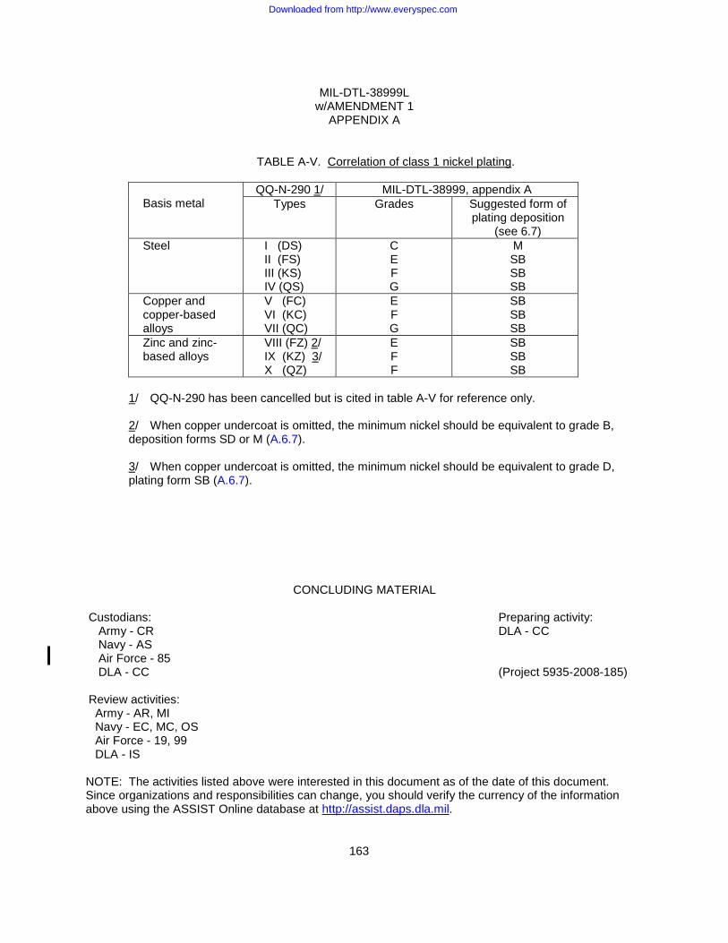
MIL-DTL-38999L w/AMENDMENT 1
APPENDIX A
163
TABLE A-V. Correlation of class 1 nickel plating.
Basis metal
QQ-N-290 1/ MIL-DTL-38999, appendix A Types Grades Suggested form of
plating deposition (see 6.7)
Steel I (DS) II (FS) III (KS) IV (QS)
C E F G
M SB SB SB
Copper and copper-based alloys
V (FC) VI (KC) VII (QC)
E F G
SB SB SB
Zinc and zinc-based alloys
VIII (FZ) 2/ IX (KZ) 3/ X (QZ)
E F F
SB SB SB
1/ QQ-N-290 has been cancelled but is cited in table A-V for reference only. 2/ When copper undercoat is omitted, the minimum nickel should be equivalent to grade B, deposition forms SD or M (A.6.7). 3/ When copper undercoat is omitted, the minimum nickel should be equivalent to grade D, plating form SB (A.6.7).
CONCLUDING MATERIAL
Custodians: Preparing activity: Army - CR DLA - CC Navy - AS Air Force - 85 DLA - CC (Project 5935-2008-185) Review activities: Army - AR, MI Navy - EC, MC, OS Air Force - 19, 99 DLA - IS NOTE: The activities listed above were interested in this document as of the date of this document. Since organizations and responsibilities can change, you should verify the currency of the information above using the ASSIST Online database at http://assist.daps.dla.mil.
Downloaded from http://www.everyspec.com