Embed Size (px)
Citation preview

IndustrialHydraulics
Electric Drivesand Controls
Linear Motion andAssembly Technologies
ServiceAutomation
MobileHydraulicsPneumatics
Inch Series Aluminum Structural Framing Catalog
“Everything to Build Anything”
Version 1.0

1–0
1
Bosch Aluminum Structural Framing
© 2003, Bosch Rexroth Corporation, No. 8981500308 03/03
NOTICE: No freedom from any patent owned by Seller or others is to be inferred. Because use conditions and applicable laws may differ from onelocation to another and may change with time, Customer is responsible for determining whether products and the information in this document areappropriate for Customer’s use and for ensuring that Customer’s workplace and disposal practices are in compliance with applicable laws and othergovernmental enactments. Seller assumes no obligation or liability for the information in this document. NO WARRANTIES ARE GIVEN; ALLIMPLIED WARRANTIES OF MERCHANTABILITY OR FITNESS FOR A PARTICULAR PURPOSE ARE EXPRESSLY EXCLUDED.
Introduction How to Use This Catalog Fraction and English/Metric Conversion Chart Pictorial Overview of SectionsProfiles
Profile Connectors
Fasteners
Door and Enclosure Components
Floor to Frame Elements
Finishing Elements and Accessories
Tools
Engineering Data and Specifications
Product Part Numbering Index
Section No.
1
23456789
10
Table of Contents

1
Introduction
Section 1—Introduction
1–1
Do you know why you’re seeingmore and more metal structuresmade of aluminum structuralframing from Bosch Rexrothrather than welded steel? Simple.Our framing costs less, is moreversatile, and does a better jobthan steel. And perhaps mostimportant, it’s easier to work with.
That’s because at the heart of thesystem is the framing’s T-slotdesign: insert a T-bolt intoa T-slot and tighten. It’s thatsimple. No welding, no grinding,no nothing. Your frame goestogether quickly and easily usinga few simple hand tools. Thenchoosing from a wide assortmentof accessories, you add whatevercomponents you want just as easily.
And when you’re done, you havea strong, lightweight structurethat’s as functional as it isattractive. The high-strengthextruded aluminum profiles havea natural-color, anodized surfacethat’s scratch- and corrosion-resistant, never needs painting,and is maintenance-free.
More things can be built,more ways to build them
With Rexroth aluminum structuralframing, you can build just aboutanything you can imagine. Thisincludes, work tables, machinebases, industrial guarding, toolracks, robot stands, workstations,carts, display units, and muchmore.
And all Rexroth products areengineered to work together.That means they fit togetherprecisely, align accurately, andare assembled quickly. OurT-slots allow the use of largerand stronger hardware. So onceyou put a structure together,it stays together.
Made in U.S.A.
Although Bosch inventedaluminum structural framing inEurope over 20 years ago, todaymost of the material used in thesystem is made in America and,of course, is stocked here, too.In fact, all North American BoschRexroth distributors maintain acomplete inventory of almost allthe items shown in this catalog.
Need assistance? Ready toorder?
We realize every question you haveprobably won’t be answered by thiscatalog. So call 1-800-322-6724, andsomeone from our fully trainedstaff will be happy to help you.Or they can provide you with thename and phone number of theauthorized Bosch distributornearest you to help you get started.

1
Aluminum Structural Framing1–2
How To Use This Catalog
For an overview of profilesavailable and their technicalspecifications, see page 2-0.
In the “Profiles” section, you willsee drawings of the actual profileat the top of each page that looklike this:
Select the profilebased on your load.1 You can factory order several
different machining options forprofiles, such as pre-drilledthrough-holes are tapped centerbores. Machining options areindicated in both the descriptionand with a graphic iconrepresenting the location.Detailed descriptions anddimensional information formachining options is shown onpage 2-1.
You will also find an end-viewof each profile with dimensionalinformation like the one below.Accessories and other componentswill also have dimensionaldrawings, with other relevantinformation such as fastener sizesindicated.
Ø0.39″
0.41″
0.39″
1.50
″
0.75″
1.50″
2
Aluminum Structural Framing2–4
Technical Data
Moment of inertia Ix = 0.554 in4
Iy = 0.554 in4
Section modulus Wx = 0.554 in3
Wy = 0.554 in3
Profile surface A = 1.226 in2
Weight 1.434 lbs/ft
Description End Machining Part Number
Profile 2x2, Pkg. 20, 240 long 8 981 021 391
Profile 2x2, single, 240 long 8 981 021 400
Profile 2x2, –/–, Single, square cut to length, 1.25 240 8 981 992 332/__in*
Profile 2x2, –/D5⁄16, Single, 1.25 240 8 981 992 333/__in*
Profile 2x2, –/D33⁄64, Single, 1.25 240 8 981 992 334/__in*
Profile 2x2, D5⁄16/D5⁄16, Single, 1.50 240 8 981 992 335/__in*
Profile 2x2, D33⁄64/D33⁄64, Single, 2.50 240 8 981 992 336/__in*
Profile 2x2, D33⁄64/D33⁄64VS, Single, 2.50 240 8 981 992 337/__in*
Profile 2x2, –/1⁄4-20, Single, 2.50 240 8 981 992 404/__in*
Profile 2x2, D5⁄16/1⁄4-20, Single, 2.50 240 8 981 992 405/__in*
*Specify length in 1/16 increments
2 x 2
Ideal for medium- to heavy-dutyconstruction. 2 x 2 profile haseight #8 T-slots and is used withother #8 accessories and fastenersin this catalog.Minimum length: 1.25 Maximum length: 240
ÿ0.23
0.31
0.32
1.00
2.00
0.50 2.00
8
8

1
Introduction 1–3
3
(1)(2)
(3)
(4)
2
Select theaccessories youneed to completeyour structure.
Select theconnectors thatwill give you oryour structure thedesired features.
Rexroth offers four groups ofconnectors based on function.For example, some connectorsprovide (1) 90° right angleconnections for two profiles,(2) variable angle connections,(3) end-to-end connections, and(4) cross connections. So yourfirst step in selecting a connectoris to determine what kind ofconnection you need to do thejob you want. Your next step isto determine what features youwant in the connector groupyou’ve selected.
Rexroth offers a wide variety ofaccessories for building machinebases, guarding elements,stands, partitions, display cases,end-of-arm tooling, conveyorleg sets, and much more.
For example, some connectorsgive you more flexibility andallow you to quickly change orrearrange your structure; someare stronger, some cost less, someprovide concealed connectionsfor a better appearance, someprovide complete access tothe T-slot, and some requiremachining of the profile end(tapped, drilled, or square cut).To determine which typeof connector will give you thebest combination of price,performance, and function—based on your application—talkto your authorized BoschRexroth distributor.

1
Aluminum Structural Framing1–4
What You Should Know To HelpYou Get Around This Catalog1.All dimensions in this catalog
are in inches. An English/Metricconversion table and QuickConversion chart for convertingcommon fractions to decimalsare shown on page 1-5, as well asat the back of the catalog.
2.A guide to common profile termsand how to recognize what isincluded when ordering acomponent or kit is also shownon page 1-5.
Below are symbols you’ll see throughout this catalog. You can use thesymbols to quickly identify compatibility between profile, connector,fastener and accessories.
3.Profiles ordered in bundles areavailable only in maximumlengths. Single profiles can beordered in any length and withany type of standard endfinish, either machined ornon-machined. When orderingsingles square cut to length,be sure to specify the lengthin inches to the closest 1/16th(0.063″) of an inch after thepart number.Example:The part number for a 1″ x 1″profile, square cut to 969⁄16″,would be:8 981 992 318/96.563.
4.The maximum length listedfor each profile and othercomponents is the usable length.This means the components mayactually be longer toaccommodate anodizing andother manufacturing processes.
Symbol What it means Symbol What it means
Greater than or equal to/Less than or equal to. Used to specify the available size range for cut-to-order profiles, e.g. ≥ 1.25″ ≤ 240″indicates a minimum ordering length of 1.25″ and maximum of 240″. NOTE: Always specify lengths to the closest 1/16″ (0.063″).
Indicates diameter, such as in drilled holes or shaft thicknesses.
Button Head Cap ScrewBHCS
Flanged Button Head Cap ScrewFBHCS
Profile has a #8 (0.32″ wide) T-slot. Use any profiles, fasteners, or accessories with the same symbol to insure compatabilty.
Profile has a #10 (0.39″ wide) T-slot. Use any profiles, fasteners, or accessories with the same symbol to insure compatabilty.
Use this component to join profiles with a #8 T-slot to another profile with a #8 T-slot.
Use this component to join profiles with a #8 T-slot to a profile with a #10 T-slot.
Use this component to join profiles with a #10 T-slot to another profile with a #10 T-slot.

1
Introduction
Identifying profile components:
1–5
English/Metric Conversion Chart
Multiply By To Get
Linear Millimeters (mm) .03937 InchesInches 25.4 Millimeters (mm)
Area Millimeters2 (mm2) .00155 Inches2
Inches2 645.16 Millimeters2 (mm2)Volume Centimeters3 (cm3) .06102 Inches3
Inches3 16.387 Centimeters3 (cm3)Inches3 .0164 LitersLiters 61.024 Inches3
Velocity Meters/Minute 3.281 Feet/MinuteFeet/Minute .3048 Meters/Minute
Force Kilograms-f (kgf) 9.807 Newtons (N)Newtons (N) .10194 Kilograms-f (kgf)Pounds-f 4.448 Newtons (N)Newtons (N) .2248 Pounds-f
Pressure Bar 14.5 PSIPSI .069 Bar
Torque Newton-Meters (Nm) 8.851 Pounds-InchesPound-Inches .11298 Newton-Meters (Nm)
Moment of Inertia Centimeters4 (cm4) .02403 inch4 (in4)Inches4 (in4) 41.623 centimeters4 (cm4)
What prefixes and suffixes mean:S1/2 Self-Tapping Screw: S=self-tapping1.5 x 1.5H: H=heavy duty
Other specialty profiles and com-ponents may carry suffixes that areexplained in the description onthat item’s catalog page.
When components in drawingsshowing multiple items (such asa connector and profiles, as seenhere) are shaded gray, it meansthey are included with your order.For example, when you orderthe quick connector/rigid (partnumber 8 981 021 601), the kitincludes a setscrew, barrel, andT-connector as shown.
What is included?
Common profile terms
Quick Conversion Chart
Fraction Decimal
1/16 0.0631/8 0.125
3/16 0.1881/4 0.25
5/16 0.3133/8 0.375
7/16 0.4381/2 0.50
9/16 0.5635/8 0.625
11/16 0.6883/4 0.75
13/16 0.8137/8 0.875
15/16 0.938
1
Aluminum Structural Framing1–6
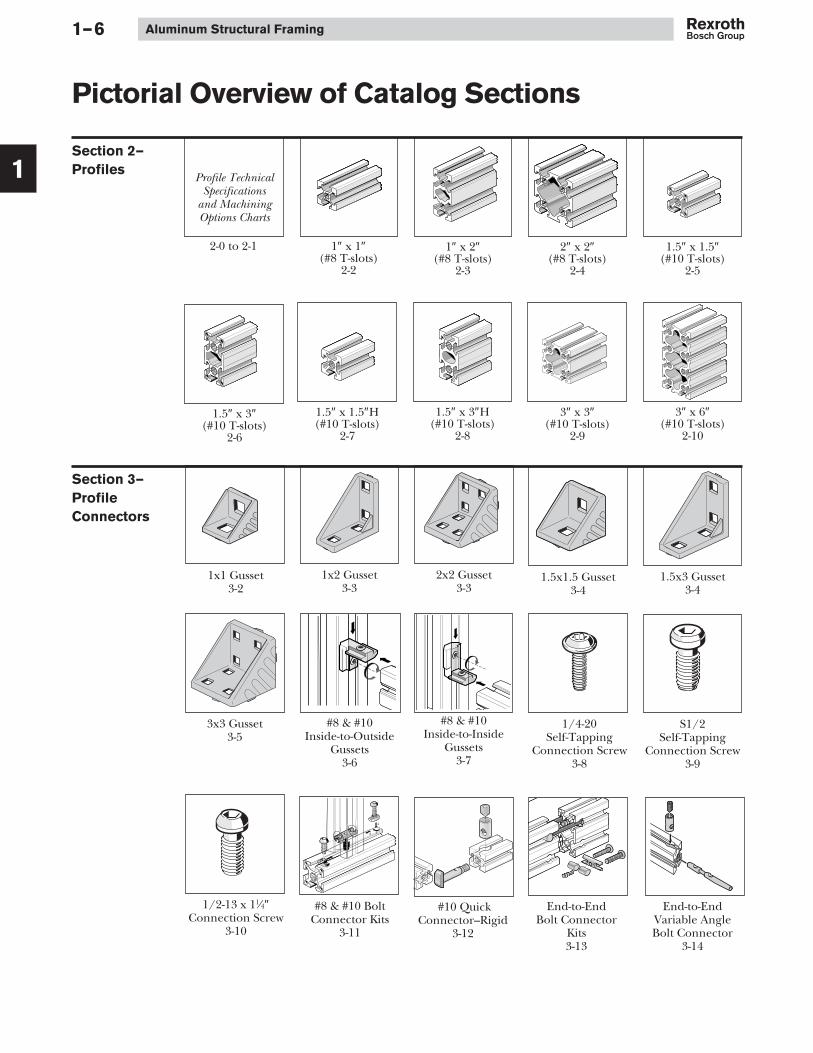
Section 2—
Profiles
Pictorial Overview of Catalog Sections
2-0 to 2-1
Profile TechnicalSpecifications
and MachiningOptions Charts
1″ x 1″(#8 T-slots)
2-2
3″ x 3″(#10 T-slots)
2-9
1.5″ x 3″(#10 T-slots)
2-6
1.5″ x 1.5″(#10 T-slots)
2-5
1″ x 2″(#8 T-slots)
2-3
3″ x 6″(#10 T-slots)
2-10
1.5″ x 1.5″H(#10 T-slots)
2-7
1.5″ x 3″H(#10 T-slots)
2-8
2″ x 2″(#8 T-slots)
2-4
1x2 Gusset3-3
2x2 Gusset3-3
1x1 Gusset3-2
1/4-20Self-Tapping
Connection Screw3-8
#8 & #10Inside-to-Inside
Gussets3-7
#8 & #10Inside-to-Outside
Gussets3-6
1.5x3 Gusset3-4
3x3 Gusset3-5
1.5x1.5 Gusset3-4
S1/2Self-Tapping
Connection Screw3-9
1/2-13 x 11⁄4″Connection Screw
3-10
#8 & #10 BoltConnector Kits
3-11
#10 QuickConnector–Rigid
3-12
End-to-EndBolt Connector
Kits3-13
End-to-EndVariable AngleBolt Connector
3-14
Section 3—
Profile
Connectors
1
23

1
Introduction 1–7
Corner JoiningPlates
3-17 & 3-18
T-JunctionJoining Plates
3-19 & 3-20
End-to-SideVariable AngleBolt Connector
3-15
#8 & #10Connection Link
Kits3-16
Cross JunctionJoining Plates
3-21 & 3-22
RectangularJoining Strips
3-23
Section 4—
Fasteners
Square Nut4-2
T-Nuts4-1
Anti-RotationT-Blocks
4-4
#10 Swivel-InT-Bar
4-6
#10 Swivel-InT-Blocks
4-5
#10 T-BoltFastening Kits
4-3

1
Aluminum Structural Framing1–8
Panel Sliders5-3
Snap-In SlidingDoor Guides
5-2
Bar Handle5-5
Lift-Off Hinges5-7
Heavy-DutyHinges
5-6
Strap Handles5-4
Compact Lock5-9
Door Stops5-8
Heavy-Duty BallDetent Latch
5-12
Door Seals5-13
Magnetic Latch5-10
Ball DetentLatch5-11
BOSCH
#8 Glazing Strip5-15
#10 Panel SupportInserts
5-14
Section 5—Door andEnclosureComponents
Leveling Feet6-1 & 6-2
Leveling FootPlates for 2x2 &
3x3 Profiles6-3
Threaded Sleevefor Leveling Feet
6-3
Base Plates andAnchor Bolt
6-6
Plate-MountedCasters
6-4
Die-CastFoundation
Bracket6-5
Section 6—Floor to FrameElements

1
Introduction 1–9
Section 7—
Finishing
Elements and
Accessories
T-Slot Covers7-3
End Caps forStructural Profiles
7-2
AluminumT-Slot Covers
7-4
Swivel Bracket7-6
Locking Lever7-5
R-A-M® Mount7-7
Section 8—
Tools
Section 9—Engineering Data and Specifications
Section 10—Product Part Numbering Index
Thread Taps8-1
Drill Bits8-2
How to CutProfiles
8-1
#10 Drilling andBoring Jig
8-3
Ball PointL-Wrenches
8-5
Cleaning Block8-5
#10 Miter DrillingJigs8-4
#8 Drilling andBoring Jig
8-3

2
Aluminum Structural Framing2–0
Section 2—T-Slotted ProfilesTechnical Specifications
Moment of inertia
Section modulus
Profile surface
Weight (Mass)
T-slot
Page
0.044
0.044
0.088
0.088
0.404
0.473
2-2
0.085
0.296
0.171
0.296
0.833
0.975
2-3
0.554
0.554
0.554
0.554
1.226
1.434
2-4
0.254
0.254
0.338
0.338
1.095
1.282
2-6
0.193
0.193
0.257
0.257
0.908
1.063
2-5
0.387
1.410
0.516
0.940
1.711
2.002
2-7
0.479
1.755
0.639
1.170
2.139
2.502
2-8
3.346
3.346
2.230
2.230
3.537
4.138
2-9
6.540
22.666
4.360
7.555
6.494
7.598
2-10
A[in2]
m[lbs/ft]
Wx[in3]
Wy[in3]
Iy[in4]
Ix[in4]
1x1 1x2 2x2 3x31.5x1.5 1.5x1.5H 1.5x3 1.5x3H 3x6
8 8 8 10 10 10 10 10 10

2
Profiles 2–1
T-Slotted ProfilesEnd Machining Options
1/2-13
D 5/16
D 5/16V
D33/64
D33/64V
D37/64
.50″
5/16″
5/16
33/64″
33/64″
D37/64V
.750″D3/8
3/8″
.750″
.750″
.50″
1/2-
13
1/4-20
1.575″
1/4-
20
3.346″
37/64″
.964″
37/64″
.964″

2
Aluminum Structural Framing2–2
Technical Data
Moment of inertia Ix = 0.044 in4
Iy = 0.044 in4
Section modulus Wx = 0.088 in3
Wy = 0.088 in3
Profile surface A = 0.404 in2
Weight 0.473 lbs/ft
Description End Machining Part Number
Profile 1x1, Pkg. 20, 240″ long 8 981 021 389
Profile 1x1, single, 240″ long 8 981 021 398
Profile 1x1, –/–, Single, square cut to length, ≥ 1.25″ ≤ 240″ 8 981 992 318/__in*
Profile 1x1, –/D5⁄16, Single, ≥ 1.25″ ≤ 240″ 8 981 992 319/__in*
Profile 1x1, –/D33⁄64, Single, ≥ 1.25″ ≤ 240″ 8 981 992 320/__in*
Profile 1x1, D5⁄16/D5⁄16, Single, ≥ 1.50″ ≤ 240″ 8 981 992 321/__in*
Profile 1x1, D33⁄64/D33⁄64, Single, ≥ 2.50″ ≤ 240″ 8 981 992 322/__in*
Profile 1x1, D33⁄64/D33⁄64VS, Single, ≥ 2.50″ ≤ 240″ 8 981 992 323/__in*
Profile 1x1, –/1⁄4-20, Single, ≥ 2.50″ ≤ 240″ 8 981 992 400/__in*
Profile 1x1, D5⁄16/1⁄4-20, Single, ≥ 2.50″ ≤ 240″ 8 981 992 401/__in*
*Specify length in 1/16″ increments
T-Slotted Profiles
1″ x 1″
Ideal for light-duty construction.1″ x 1″ profile has four #8 T-slotsand is used with other #8accessories and fastenersin this catalog.Minimum length: 1.25″Maximum length: 240″ Ø0.23″
0.32″
0.31″
1.00
″
0.50″
1.00″
8
8

2
Profiles 2–3
Technical Data
Moment of inertia Ix = 0.085 in4
Iy = 0.296 in4
Section modulus Wx = 0.171 in3
Wy = 0.296 in3
Profile surface A = 0.833 in2
Weight 0.975 lbs/ft
Description End Machining Part Number
Profile 1x2, Pkg. 20, 240″ long 8 981 021 390
Profile 1x2, single, 240″ long 8 981 021 399
Profile 1x2, –/–, Single, square cut to length, ≥ 1.25″ ≤ 240″ 8 981 992 324/__in*
Profile 1x2, –/D5⁄16, Single, ≥ 1.25″ ≤ 240″ 8 981 992 325/__in*
Profile 1x2, –/D33⁄64, Single, ≥ 1.25″ ≤ 240″ 8 981 992 326/__in*
Profile 1x2, –/D33⁄64VS, Single, ≥ 1.25″ ≤ 240″ 8 981 992 327/__in*
Profile 1x2, D5⁄16/D5⁄16, Single, ≥ 1.50″ ≤ 240″ 8 981 992 328/__in*
Profile 1x2, D33⁄64/D33⁄64, Single, ≥ 2.50″ ≤ 240″ 8 981 992 329/__in*
Profile 1x2, D33⁄64/D33⁄64VS, Single, ≥ 2.50″ ≤ 240″ 8 981 992 330/__in*
Profile 1x2, –/1⁄4-20, Single, ≥ 2.50″ ≤ 240″ 8 981 992 402/__in*
Profile 1x2, D5⁄16/1⁄4-20, Single, ≥ 2.50″ ≤ 240″ 8 981 992 403/__in*
*Specify length in 1/16″ increments
1″ x 2″
Ideal for light- to medium-dutyconstruction. 1″ x 2″ profile hassix #8 T-slots and is used withother #8 accessories and fastenersin this catalog.Minimum length: 1.25″Maximum length: 240″
Ø0.23″
0.31″
0.32″
1.00
″
2.00
″
0.50″
1.00″
8
8

2
Aluminum Structural Framing2–4
Technical Data
Moment of inertia Ix = 0.554 in4
Iy = 0.554 in4
Section modulus Wx = 0.554 in3
Wy = 0.554 in3
Profile surface A = 1.226 in2
Weight 1.434 lbs/ft
Description End Machining Part Number
Profile 2x2, Pkg. 20, 240″ long 8 981 021 391
Profile 2x2, single, 240″ long 8 981 021 400
Profile 2x2, –/–, Single, square cut to length, ≥ 1.25″ ≤ 240″ 8 981 992 332/__in*
Profile 2x2, –/D5⁄16, Single, ≥ 1.25″ ≤ 240″ 8 981 992 333/__in*
Profile 2x2, –/D33⁄64, Single, ≥ 1.25″ ≤ 240″ 8 981 992 334/__in*
Profile 2x2, D5⁄16/D5⁄16, Single, ≥ 1.50″ ≤ 240″ 8 981 992 335/__in*
Profile 2x2, D33⁄64/D33⁄64, Single, ≥ 2.50″ ≤ 240″ 8 981 992 336/__in*
Profile 2x2, D33⁄64/D33⁄64VS, Single, ≥ 2.50″ ≤ 240″ 8 981 992 337/__in*
Profile 2x2, –/1⁄4-20, Single, ≥ 2.50″ ≤ 240″ 8 981 992 404/__in*
Profile 2x2, D5⁄16/1⁄4-20, Single, ≥ 2.50″ ≤ 240″ 8 981 992 405/__in*
*Specify length in 1/16″ increments
2″ x 2″
Ideal for medium- to heavy-dutyconstruction. 2″ x 2″ profile haseight #8 T-slots and is used withother #8 accessories and fastenersin this catalog.Minimum length: 1.25″Maximum length: 240″
Ø0.23″
0.31″
0.32″
1.00
″
2.00
″
0.50″2.00″
8
8
2
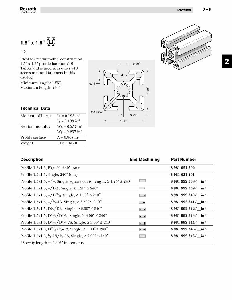
Profiles 2–5
Technical Data
Moment of inertia Ix = 0.193 in4
Iy = 0.193 in4
Section modulus Wx = 0.257 in3
Wy = 0.257 in3
Profile surface A = 0.908 in2
Weight 1.063 lbs/ft
Description End Machining Part Number
Profile 1.5x1.5, Pkg. 20, 240″ long 8 981 021 392
Profile 1.5x1.5, single, 240″ long 8 981 021 401
Profile 1.5x1.5, –/–, Single, square cut to length, ≥ 1.25″ ≤ 240″ 8 981 992 338/__in*
Profile 1.5x1.5, –/D3⁄8, Single, ≥ 1.25″ ≤ 240″ 8 981 992 339/__in*
Profile 1.5x1.5, –/D37⁄64, Single, ≥ 1.50″ ≤ 240″ 8 981 992 340/__in*
Profile 1.5x1.5, –/1⁄2–13, Single, ≥ 3.50″ ≤ 240″ 8 981 992 341/__in*
Profile 1.5x1.5, D3⁄8/D3⁄8, Single, ≥ 2.00″ ≤ 240″ 8 981 992 342/__in*
Profile 1.5x1.5, D37⁄64/D37⁄64, Single, ≥ 3.00″ ≤ 240″ 8 981 992 343/__in*
Profile 1.5x1.5, D37⁄64/D37⁄64VS, Single, ≥ 3.00″ ≤ 240″ 8 981 992 344/__in*
Profile 1.5x1.5, D37⁄64/1⁄2–13, Single, ≥ 5.00″ ≤ 240″ 8 981 992 345/__in*
Profile 1.5x1.5, 1⁄2–13/1⁄2–13, Single, ≥ 7.00″ ≤ 240″ 8 981 992 346/__in*
*Specify length in 1/16″ increments
1.5″ x 1.5″
Ideal for medium-duty construction.1.5″ x 1.5″ profile has four #10T-slots and is used with other #10accessories and fasteners in thiscatalog.Minimum length: 1.25″Maximum length: 240″
Ø0.39″
0.41″
0.39″
1.50
″
0.75″
1.50″
10
10

2
Aluminum Structural Framing2–6
Technical Data
Moment of inertia Ix = 0.254 in4
Iy = 0.254 in4
Section modulus Wx = 0.338 in3
Wy = 0.338 in3
Profile surface A = 1.095 in2
Weight 1.282 lbs/ft
Description End Machining Part Number
Profile 1.5x1.5H, Pkg. 20, 240″ long 8 981 021 393
Profile 1.5x1.5H, single, 240″ long 8 981 021 402
Profile 1.5x1.5H, –/–, Single, square cut to length, ≥ 1.25″ ≤ 240″ 8 981 992 347/__in*
Profile 1.5x1.5H, –/D3⁄8, Single, ≥ 1.25″ ≤ 240″ 8 981 992 348/__in*
Profile 1.5x1.5H, –/D37⁄64, Single, ≥ 1.50″ ≤ 240″ 8 981 992 349/__in*
Profile 1.5x1.5H, –/1⁄2–13, Single, ≥ 3.50″ ≤ 240″ 8 981 992 350/__in*
Profile 1.5x1.5H, D3⁄8/D3⁄8, Single, ≥ 2.00″ ≤ 240″ 8 981 992 351/__in*
Profile 1.5x1.5H, D37⁄64/D37⁄64, Single, ≥ 3.00″ ≤ 240″ 8 981 992 352/__in*
Profile 1.5x1.5H, D37⁄64/D37⁄64VS, Single, ≥ 3.00″ ≤ 240″ 8 981 992 353/__in*
Profile 1.5x1.5H, D37⁄64/1⁄2–13, Single, ≥ 5.00″ ≤ 240″ 8 981 992 354/__in*
Profile 1.5x1.5H, 1⁄2–13/1⁄2–13, Single, ≥ 7.00″ ≤ 240″ 8 981 992 355/__in*
*Specify length in 1/16″ increments
1.5″ x 1.5″H
Ideal for medium-duty construction.1.5″ x 1.5″H profile has four #10T-slots and is used with other #10accessories and fasteners in thiscatalog.Minimum length: 1.25″Maximum length: 240″
Ø0.39″
0.41″
0.39″
1.50
″
0.75″
1.50″
10
10

2
Profiles 2–7
Technical Data
Moment of inertia Ix = 0.387 in4
Iy = 1.410 in4
Section modulus Wx = 0.516 in3
Wy = 0.940 in3
Profile surface A = 1.711 in2
Weight 2.002 lbs/ft
Description End Machining Part Number
Profile 1.5x3, Pkg. 12, 240″ long 8 981 021 394
Profile 1.5x3, single, 240″ long 8 981 021 403
Profile 1.5x3, –/–, Single, square cut to length, ≥ 1.25″ ≤ 240″ 8 981 992 356/__in*
Profile 1.5x3, –/D3⁄8, Single, ≥ 1.25″ ≤ 240″ 8 981 992 357/__in*
Profile 1.5x3, –/D37⁄64, Single, ≥ 1.50″ ≤ 240″ 8 981 992 358/__in*
Profile 1.5x3, –/D37⁄64VS, Single, ≥ 1.50″ ≤ 240″ 8 981 992 359/__in*
Profile 1.5x3, –/1⁄2–13, Single, ≥ 3.50″ ≤ 240″ 8 981 992 360/__in*
Profile 1.5x3, D3⁄8/D3⁄8, Single, ≥ 2.00″ ≤ 240″ 8 981 992 361/__in*
Profile 1.5x3, D37⁄64/D37⁄64, Single, ≥ 3.00″ ≤ 240″ 8 981 992 362/__in*
Profile 1.5x3, D37⁄64/D37⁄64VS, Single, ≥ 3.00″ ≤ 240″ 8 981 992 363/__in*
Profile 1.5x3, D37⁄64/1⁄2–13, Single, ≥ 5.00″ ≤ 240″ 8 981 992 364/__in*
Profile 1.5x3, 1⁄2–13/1⁄2–13, Single, ≥ 7.00″ ≤ 240″ 8 981 992 367/__in*
*Specify length in 1/16″ increments
1.5″ x 3″
Ideal for medium-duty construction.1.5″ x 3″ profile has six #10 T-slotsand is used with other #10accessories and fasteners in thiscatalog.Minimum length: 1.25″Maximum length: 240″
Ø0.39″
0.41″
0.39″
1.50
″
3.00
″0.75″
1.50″
10
10

2
Aluminum Structural Framing2–8
Technical Data
Moment of inertia Ix = 0.479 in4
Iy = 1.754 in4
Section modulus Wx = 0.639 in3
Wy = 1.170 in3
Profile surface A = 2.139 in2
Weight 2.502 lbs/ft
Description End Machining Part Number
Profile 1.5x3H, Pkg. 12, 240″ long 8 981 021 395
Profile 1.5x3H, single, 240″ long 8 981 021 404
Profile 1.5x3H, –/–, Single, square cut to length, ≥ 1.25″ ≤ 240″ 8 981 992 368/__in*
Profile 1.5x3H, –/D3⁄8, Single, ≥ 1.25″ ≤ 240″ 8 981 992 369/__in*
Profile 1.5x3H, –/D37⁄64, Single, ≥ 1.50″ ≤ 240″ 8 981 992 370/__in*
Profile 1.5x3H, –/D37⁄64VS, Single, ≥ 1.50″ ≤ 240″ 8 981 992 371/__in*
Profile 1.5x3H, –/1⁄2–13, Single, ≥ 3.50″ ≤ 240″ 8 981 992 372/__in*
Profile 1.5x3H, D3⁄8/D3⁄8, Single, ≥ 2.00″ ≤ 240″ 8 981 992 373/__in*
Profile 1.5x3H, D37⁄64/D37⁄64, Single, ≥ 3.00″ ≤ 240″ 8 981 992 374/__in*
Profile 1.5x3H, D37⁄64/D37⁄64VS, Single, ≥ 3.00″ ≤ 240″ 8 981 992 375/__in*
Profile 1.5x3H, D37⁄64/1⁄2–13, Single, ≥ 5.00″ ≤ 240″ 8 981 992 376/__in*
Profile 1.5x3H, 1⁄2–13/1⁄2–13, Single, ≥ 7.00″ ≤ 240″ 8 981 992 379/__in*
*Specify length in 1/16″ increments
1.5″ x 3″H
Ideal for heavy-duty construction.1.5″ x 3″H profile has six #10T-slots and is used with other#10 accessories and fastenersin this catalog.Minimum length: 1.25″Maximum length: 240″
10
10
Ø0.39″
0.41″
0.39″
1.50
″3.
00″
0.75″
1.50″

2
Profiles
Technical Data
Moment of inertia Ix = 3.346 in4
Iy = 3.346 in4
Section modulus Wx = 2.230 in3
Wy = 2.230 in3
Profile surface A = 3.537 in2
Weight 4.138 lbs/ft
Description End Machining Part Number
Profile 3x3, Pkg. 6, 240″ long 8 981 021 396
Profile 3x3, single, 240″ long 8 981 021 405
Profile 3x3, –/–, Single, square cut to length, ≥ 1.25″ ≤ 240″ 8 981 992 380/__in*
Profile 3x3, –/D3⁄8, Single, ≥ 1.25″ ≤ 240″ 8 981 992 381/__in*
Profile 3x3, –/D37⁄64, Single, ≥ 1.50″ ≤ 240″ 8 981 992 382/__in*
Profile 3x3, –/1⁄2–13, Single, ≥ 3.50″ ≤ 240″ 8 981 992 383/__in*
Profile 3x3, D3⁄8/D3⁄8, Single, ≥ 2.00″ ≤ 240″ 8 981 992 384/__in*
Profile 3x3, D37⁄64/D37⁄64, Single, ≥ 3.00″ ≤ 240″ 8 981 992 385/__in*
Profile 3x3, D37⁄64/D37⁄64VS, Single, ≥ 3.00″ ≤ 240″ 8 981 992 386/__in*
Profile 3x3, D37⁄64/1⁄2–13, Single, ≥ 5.00″ ≤ 240″ 8 981 992 387/__in*
Profile 3x3, 1⁄2–13/1⁄2–13, Single, ≥ 7.00″ ≤ 240″ 8 981 992 388/__in*
*Specify length in 1/16″ increments
3″ x 3″
Ideal for heavy-duty construction.3″ x 3″ profile has eight #10T-slots and is used with other#10 accessories and fastenersin this catalog.Minimum length: 1.25″Maximum length: 240″
0.39″
Ø0.39″
0.41″
3.00
″
0.75″
3.00″1.50″
2–9
10
10

2
Aluminum Structural Framing
Technical Data
Moment of inertia Ix = 6.540 in4
Iy = 22.666 in4
Section modulus Wx = 4.360 in3
Wy = 7.555 in3
Profile surface A = 6.494 in2
Weight 7.598 lbs/ft
Description End Machining Part Number
Profile 3x6, Pkg. 3, 240″ long 8 981 021 397
Profile 3x6, single, 240″ long 8 981 021 406
Profile 3x6, –/–, Single, square cut to length, ≥ 1.25″ ≤ 240″ 8 981 992 389/__in*
Profile 3x6, –/D37⁄64, Single, ≥ 1.25″ ≤ 240″ 8 981 992 391/__in*
Profile 3x6, –/1⁄2–13, Single, ≥ 3.50″ ≤ 240″ 8 981 992 393/__in*
Profile 3x6, D37⁄64/D37⁄64, Single, ≥ 3.00″ ≤ 240″ 8 981 992 394/__in*
Profile 3x6, D37⁄64/1⁄2–13, Single, ≥ 5.00″ ≤ 240″ 8 981 992 396/__in*
Profile 3x6, D37⁄64VS/D37⁄64VS, Single, ≥ 3.00″ ≤ 240″ 8 981 992 397/__in*
Profile 3x6, 1⁄2–13/1⁄2–13, Single, ≥ 7.00″ ≤ 240″ 8 981 992 399/__in*
*Specify length in 1/16″ increments
3″ x 6″
Ideal for heavy-duty construction.3″ x 6″ profile has twelve #10 T-slotsand is used with other #10accessories and fasteners inthis catalog.Minimum length: 1.25″Maximum length: 240″
0.39″
Ø0.39″
0.41″
0.75″3.00″
1.50
″1.
50″
6.00
″1.
50″
2–10
10
10

3
Profile Connectors 3–1
Section 3—Profile Connectors
One of the greatest strengths ofthe Bosch structural aluminumframing system is the wide choiceof connection methods, and theability to provide the rightconnection regardless of
1x2 Gusset3-3
2x2 Gusset3-3
1x1 Gusset3-2
1/4-20Self-Tapping
Connection Screw3-8
90° Right Angle Connectors
#8 & #10Inside-to-Inside
Gussets3-7
Corner JoiningPlates
3-17 & 3-18
T-Junction Joining Plates
3-19 & 3-20
Joining Plates
application. Strength, flexibility,or aesthetics, or a combinationof all these advantages, are typicalof all Bosch Rexroth connectorsand fasteners.
#8 & #10Inside-to-Outside
Gussets3-6
1.5x3 Gusset3-4
3x3 Gusset3-5
1.5x1.5 Gusset3-4
S1/2Self-Tapping
Connection Screw3-9
1/2-13 x 11⁄4″Connection Screw
3-10
#8 & #10 BoltConnector Kits
3-11
#10 QuickConnector–Rigid
3-12
End-to-EndBolt Connector
Kits3-13
End-to-EndVariable AngleBolt Connector
3-14
End-to-SideVariable AngleBolt Connector
3-15
#8 & #10Connection Link
Kits3-16
Cross JunctionJoining Plates
3-21 & 3-22
RectangularJoining Strips
3-23
1
23

3
Aluminum Structural Framing3–2
Die-cast aluminum gussets areavailable for the new inch-seriesprofiles, in sizes 1″x1″, 1″x2″, 2″x2″,1.5″x1.5″, 1.5″x3″, and 3″x3″.Alignment tabs assure properalignment of gusset in the profile’sT-slot. Tabs can be easily removedwith a flat-tip screwdriver forcross-connection of profiles.
Machining required:• None
Material:• Gusset: die-cast aluminum• Fasteners: zinc-plated steel
TAB
Gussets
Features:• T-slot alignment tabs for easy
positioning and reducedassembly time
• Clean, professional appearance• Connects anywhere on the
profile’s T-slot• Gusset available as a separate
component• Close tolerances on gusset edges
provide flush, tight fit• Alignment tabs can easily be
removed for cross-orientedconnections
Description Qty Part Number
1x1 gusset only 1 3 842 532 163
1x1 gusset with fasteners 1 8 981 021 537
1″ x 1″ Gusset
1/4-20 x 3/8″BHCS
0.13″ 0.28″
0.29″
0.92″
0.88
″
0.65
″
8 10
8
8�8

3
Profile Connectors 3–3
Description Qty Part Number
1x2 gusset only 1 3 842 532 165
1x2 gusset with fasteners 1 8 981 021 538
1″ x 2″ Gusset
Description Qty Part Number
2x2 gusset only 1 3 842 532 167
2x2 gusset with fasteners 1 8 981 021 539
2″ x 2″ Gusset
0.13″ 0.28″
0.92″
1.88
″ 0.29″
0.64
″
1.64
″
1/4-20 x 3/8″BHCS
0.13″
1.92″
1/4-20 x 3/8″BHCS
0.29″
1.64
″0.
64″
0.28″1.00″
1.88
″
8�8
8
8�8
8
3
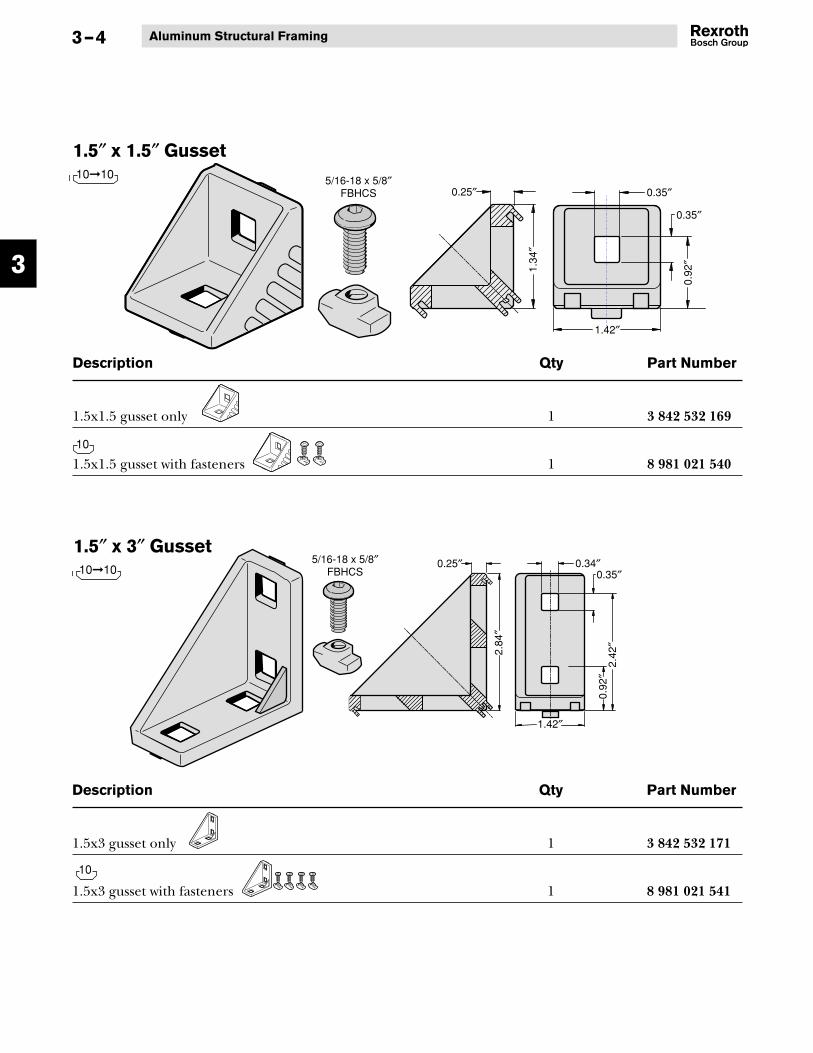
Aluminum Structural Framing3–4
Description Qty Part Number
1.5x1.5 gusset only 1 3 842 532 169
1.5x1.5 gusset with fasteners 1 8 981 021 540
1.5″ x 1.5″ Gusset
Description Qty Part Number
1.5x3 gusset only 1 3 842 532 171
1.5x3 gusset with fasteners 1 8 981 021 541
1.5″ x 3″ Gusset
0.25″
1.42″
1.34
″
0.35″
0.92
″
5/16-18 x 5/8″FBHCS 0.35″
0.25″
1.42″
2.84
″
0.35″
0.92
″2.
42″
0.34″5/16-18 x 5/8″FBHCS
10�10
10
10�10
10
3
Profile Connectors
0.25″
1.42″
2.84
″
5/16-18 x 5/8″FBHCS
0.35″
0.92
″2.
42″
0.34″
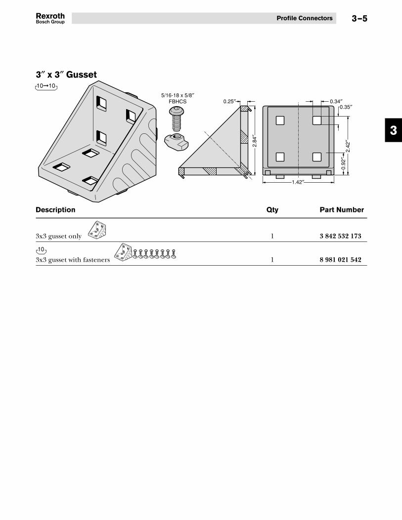
3–5
Description Qty Part Number
3x3 gusset only 1 3 842 532 173
3x3 gusset with fasteners 1 8 981 021 542
3″ x 3″ Gusset10�10
10

3
Aluminum Structural Framing3–6
#8 and #10 Inside-to-Outside Gussets
These gussets provide concealedright-angle connections whenjoining the inside #8 or #10 T-slotof one profile to the outside #8 or#10 T-slot of another profile. Thisenables you to make the type ofconnection shown at right. Thisconnection method provides easyaccess to the fastening set screws(included with connector),while the inside T-slots remainunobstructed.
Features:• Clean appearance• Easy set screw installation• Does not obstruct the T-slot
Machining required:• None
Material:• Die-cast brass
Description Part Number
A – #8 inside-to-outside gusset and set screws, package of 10 8 981 021 606
B – #10 inside-to-outside gusset and set screws, package of 10 8 981 021 607
1/4″set screw
5/16″set screw
A
B
1.18″
0.83
″
1.50″
1.26
″
8 10
10
8
10�10
8�8

3
Profile Connectors 3–7
#8 and #10 Inside-to-Inside Gussets
These gussets provide concealedright-angle connections whenjoining the inside #8 or #10 T-slotof one profile to the inside #8 or#10 T-slot of another profile. Thisenables you to make the type ofconnection shown below right.This connection method provideseasy access to the fastening setscrews (included with package)and allows adjustability of profilesafter the structure is assembled.
Features:• Clean appearance• Easy set screw installation
Machining required:• None
Material:• Die-cast brass
Description Part Number
A – #8 inside-to-inside gusset and set screws, package of 10 8 981 021 608
B – #8 to #10 inside-to-inside gusset and set screws, package of 10 8 981 021 609
C – #10 inside-to-inside gusset and set screws, package of 10 8 981 021 610
1.34
″ 1.50″
0.83
″
1.18″
1.34
″ 1.42″
A
B
C
1/4″ set screw
5/16″ set screw
8 10 8�10
8�10
8
10
1/4″ set screw
5/16″ set screw
8�10
8
10
3
Aluminum Structural Framing3–8
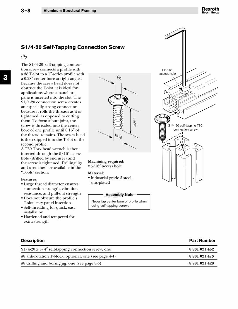
S1/4-20 Self-Tapping Connection Screw
The S1/4-20 self-tapping connec-tion screw connects a profile witha #8 T-slot to a 1″-series profile witha 0.28″ center bore at right angles.Because the screw head does notobstruct the T-slot, it is ideal forapplications where a panel orpane is inserted into the slot. TheS1/4-20 connection screw createsan especially strong connectionbecause it rolls the threads as it istightened, as opposed to cuttingthem. To form a butt joint, thescrew is threaded into the centerbore of one profile until 0.16″ ofthe thread remains. The screw headis then slipped into the T-slot of thesecond profile.A T30 Torx head wrench is theninserted through the 5/16″ accesshole (drilled by end user) andthe screw is tightened. Drilling jigsand wrenches, are available in the“Tools” section.
Features:• Large thread diameter ensures
connection strength, vibrationresistance, and pull-out strength
• Does not obscure the profile’sT-slot, easy panel insertion
• Self-threading for quick, easyinstallation
• Hardened and tempered forextra strength
Description Part Number
S1/4-20 x 3/4″ self-tapping connection screw, one 8 981 021 462
#8 anti-rotation T-block, optional, one (see page 4-4) 8 981 021 473
#8 drilling and boring jig, one (see page 8-3) 8 981 021 428
0.75
″1/4-20
T30
S1/4-20 self-tapping T30 connection screw
Ø5/16″ access hole
8
Machining required:• 5/16″ access hole
Material:• Industrial grade 5 steel,
zinc-plated

3
Profile Connectors 3–9
S1/2 Self-Tapping Connection Screw
The S1/2 self-tapping connectionscrew connects a profile with a #10T-slot to 1.5″-series profiles with a0.39″ center bore at right angles.Because the screw head does notobstruct the T-slot, it is ideal forapplications where a panel or paneis inserted into the slot. The S1/2connection screw creates anespecially strong connectionbecause it rolls the threads asit is tightened, as opposed tocutting them.To form a butt joint, the screw isthreaded into the center bore ofone profile until 0.16″ of thethread remains. The screw head isthen slipped into the T-slot of thesecond profile. A 5/16″ hex headwrench is then inserted throughthe 3/8″ access hole (drilled byend user) and the screw is tight-ened. Drilling jigs and wrenchesare available in the “Tools” section.
Features:• Large thread diameter ensures
connection strength, vibrationresistance, and pull-out strength
• Does not obscure the profile’sT-slot, easy panel access
• Self-threading for quick, easyinstallation
• Hardened and tempered forextra strength
Description Part Number
S1/2 x 1.2″ self-tapping connection screw (5/16″ hex-socket head), one 8 981 021 645
#10 anti-rotation T-block, optional, one (see page 4-4) 8 981 021 474
#10 drilling and boring jig, one (see page 8-3) 8 981 021 429
S1/2 Screw
3/8″ access hole
5/16″ hex-head wrench
1.2″
S1/2(0.421″)
5/16″
10
Machining required:• 3/8″ access hole
Material:• Industrial grade 5 steel,
zinc-plated

3
Aluminum Structural Framing3–10
1/2-13 x 11⁄4″ Connection Screw
The 1/2-13 x 11⁄4″ connection screwconnects a profile with #10T-slots to 1.5″-series profiles with0.39″ center bores at right angles.Because the screw head does notobstruct the T-slot, it is ideal forapplications where a panel or paneis inserted into the slot. To form abutt joint, the screw is threadedinto the center bore of one profileuntil 0.16″ of the thread remains.The screw head is then slippedinto the T-slot of the secondprofile. A 5/16″ hex head wrenchis then inserted through the 3/8″access hole (drilled by end user)and the screw is tightened. Drillingjigs and wrenches are available inthe “Tools” section.
Features:• Large thread diameter ensures
connection strength, vibrationresistance, and pull-out strength
• Does not obscure the profile’sT-slot, easy panel access
• Hardened and tempered forextra strength
Machining required:• 1/2-13 tap• 3/8″ access hole
Material:• Industrial grade 5 steel,
zinc-plated
Description Part Number
1/2-13 x 11⁄4″ connection screw, one 8 981 021 463
#10 anti-rotation T-block, optional, one (see page 4-4) 8 981 021 474
#10 drilling and boring jig, one (see page 8-3) 8 981 021 429
Use 1/2-13 Tap
1/2-13 x 11⁄4″ Screw
3/8″ access hole
5/16″ hex-head wrench
1.25
″1/2-13
5/16″
Assembly Note
Tap center bore in profile 1/2-13 whenusing 1/2-13 x 11⁄4″ connections screws
10

3
Profile Connectors 3–11
Bolt Connector Kits
These bolt connector kits providean extremely strong right-angleconnection for joining profiles with#8 or #10 T-slots. On profiles with#8 T-slots (such as 1x1 or 1x2), a33⁄64″ hole must be drilled throughthe side of one profile to accommo-date the barrel. On profiles with#10 T-slots (such as 1.5x1.5 or 3x3),a 37⁄64″ hole must be drilled. Kitincludes T-nuts. Because the boltconnector obscures the profile’sT-slot, panels or panes must betrimmed.
Machining required:• 33⁄64″ through-hole for #8 profiles• 37⁄64″ through-hole for #10 profiles
Material:• Hardware: industrial
grade 5 steel, zinc-plated• Cover caps and alignment pins:
black polyamide 6
Description Part Number
A 1.0″ bolt connector kit, package of 10 8 981 021 661
B 2.0″ bolt connector kit, package of 10 8 981 021 663
C 1.5″ bolt connector kit, package of 10 8 981 021 662
D 3.0″ bolt connector kit, package of 10 8 981 021 664
#8 drilling and boring jig, one (see page 8-3) 8 981 021 428
#10 drilling and boring jig, one (see page 8-3) 8 981 021 429
8 10
10
8
1
23
10
8
1.5″
2.0″
1.0″
3.0″
A
B
C
D
3
Aluminum Structural Framing3–12
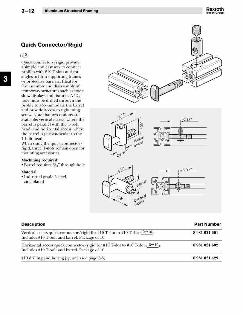
Quick Connector/Rigid
Quick connectors/rigid providea simple and easy way to connectprofiles with #10 T-slots at rightangles to form supporting framesor protective barriers. Ideal forfast assembly and disassembly oftemporary structures such as tradeshow displays and fixtures. A 37⁄64″hole must be drilled through theprofile to accommodate the barreland provide access to tighteningscrew. Note that two options areavailable: vertical access, where thebarrel is parallel with the T-bolthead; and horizontal access, wherethe barrel is perpendicular to theT-bolt head.When using the quick connector/rigid, three T-slots remain open formounting accessories.
Machining required:• Barrel requires 37⁄64″ through-hole
Material:• Industrial grade 5 steel,
zinc-plated
Description Part Number
Vertical access quick connector/rigid for #10 T-slot to #10 T-slot . 8 981 021 601Includes #10 T-bolt and barrel. Package of 10.
Horizontal access quick connector/rigid for #10 T-slot to #10 T-slot . 8 981 021 602Includes #10 T-bolt and barrel. Package of 10.
#10 drilling and boring jig, one (see page 8-3) 8 981 021 429
1.97″
1.28
″ 0.97″
0.97″
1.28″
1.97″
Horizontal
access
Vertical
access
10
10�10
10�10

3
Profile Connectors 3–13
End-to-End Bolt Connector Kits
These connector kits providea strong end-to-end connectionfor any #10 T-slotted profiles.A 37⁄64″ hole must be drilledthrough the sides of profilesto accommodate barrels. Kitsinclude cover caps to concealbolt connector and provideneat, finished appearance.Note: For precise positioning, usedrilling/boring jig 8 981 021 429.
Features:• Quick, easy installation
Machining required:• 37⁄64″ through-hole
Material:• Hardware: industrial
grade 5 steel, zinc-plated• Cover caps and alignment pins:
black polyamide 6
Description Part Number
A 1.5″ End-to-end bolt connector kit, package of 10 8 981 021 667
B 3.0″ End-to-end bolt connector kit, package of 10 8 981 021 668
#10 drilling and boring jig, one (see page 8-3) 8 981 021 429
10
3.0″
1.5″
A
B
10
10

3
Aluminum Structural Framing3–14
End-to-End Variable AngleBolt Connector
This bendable connector providesa simple and easy way to connectthe ends of profiles with #10 T-slotsat various angles. This connectorcan be bent one time at any angleup to 90˚ with a permissiblecorrection bend of up to 10˚.37⁄64″ holes must be drilled throughboth profiles to accommodate thebarrels and provide access to thetightening screws. The availabledrilling jigs provide the properend spacing for #10 T-slots.
Features:• Allows quick assembly and
disassembly• Three T-slots remain open for
mounting panels and accessories
Machining required:• 37⁄64″ through-hole required in
both profiles
Material:• Tie-rod: stainless steel• Barrel: zinc-plated steel
Description Part Number
End-to-end variable angle bolt connector , package of 10 8 981 021 603
#10 miter end-to-end drilling jig, one (see page 8-4) 8 981 021 576
Through-hole
When making angled connections, locate through-holes in the profiles as specified below.
Prior to installation, bend connector to within ±10° of desired angle
Assembly Note
10
3.94″
1.48″
1.04″
0.59″
0.57″0.39″
1.22″
0.66″
10
10

3
Profile Connectors 3–15
End-to-Side Variable AngleBolt Connector
This bendable connector providesa simple and easy way to connectthe end of one #10 profile to theside of another #10 profile atvarious angles. This connector canbe bent one time at any angle inthe range between 45° and 135°from perpendicular with a permis-sible correction bend of up to 10˚.A 37⁄64″ hole must be drilledthrough the ending profile toaccommodate the barrels andprovide access to the tighteningscrews.
Features:• Allows quick assembly and
disassembly• Three T-slots remain open for
mounting panels and accessories
Machining required:• 37⁄64″ through-hole required in
both profiles
Material:• Tie-rod: stainless steel• Barrel: zinc-plated steel
Description Part Number
End-to-side variable angle bolt connector , package of 10 8 981 021 604
#10 end-to-side miter drilling jig, one (see page 8-4) 8 981 021 597
10
2.95″0.24″0.50″
1.22″0.39″
0.66″
1.02″
0.71″
0.71″
10
10
Through-hole
When making angled connections, locate through-holes in the profiles as specified below.
Prior to installation, bend connector to within ±10° of desired angle
Assembly Note

3
Aluminum Structural Framing
#8 and #10 Connection Link Kits
These connectors provide a heavy-duty end-to-end connection forprofiles with #8 or #10 T-slots.Ideal for creating perimeterguards and conveyor rails. Allfastening hardware includedwith each connection link.
Features:• Easy assembly and disassembly• Large surface area contact with
profile T-slots allows use inheavy-duty applications
Machining required:• None
Material:• Zinc-plated steel
Description Part Number
A – #8 connection link and fastener kit, 7″ long, one 8 981 021 547
B – #10 connection link and fastener kit, 7″ long, one 8 981 021 488
A
0.79
″0.
63″
7″
7″
0.24″
0.42″
B
3–16
8 10

3
Profile Connectors
Corner Joining Platesfor 1″-series profiles
These joining plates fasten to theoutside face of profiles with a #8T-slot. They provide a strong 90°connection without interferingwith the inside T-slot.
Material:• 6063-T6 anodized aluminum• Finish: clear anodized
3 x 3 Corner Joining Plate
Description Part Number
3 x 3 corner joining plate, one 8 981 021 377
#8 1/4-20 T-nut, one 8 981 021 460
1/4-20 x 1/2″ FBHCS screw, one 8 981 021 480
Order hardware separately
2.85
″
1/4″
1.40″
2.40″
2.85″
0.40″
0.83
″0.
40″
Ø9/32″
3–17
8
8
8
8
8

3
Aluminum Structural Framing3–18
Corner Joining Platesfor 1.5″-series profiles
These joining plates fasten to theoutside face of profiles with a #10T-slot. They provide a strong 90°connection without interferingwith the inside T-slot.
Material:• 6063-T6 anodized aluminum• Finish: clear anodized
4.5 x 4.5 Corner Joining Plate 6 x 6 Corner Joining Plate
Description Part Number
4.5 x 4.5 corner joining plate, one 8 981 021 384
6 x 6 corner joining plate, one 8 981 021 376
#10 5/16-18 T-nut, one 8 981 021 324
5/16-18 x 5/8″ FBHCS screw, one 8 981 021 481
Order hardware separately Order hardware separately
1.26
″
1/4″
2.13″
3.63″
4.25″
0.63″
0.63
″
Ø11/32″
2.76
″
1/4″
5.76″
3.63″
5.13″
0.63″
0.63
″
Ø11/32″
10
10 10
10
10
10
10

3
Profile Connectors 3–19
T-Junction Joining Platesfor 1″-series profiles
These joining plates attach tothe outside face profiles with#8 T-slots. They provide astrong and convenient methodto connect profiles to form aT-connection without interferingwith the inside T-slots.
Material:• 6063-T6 anodized aluminum• Finish: clear anodized
3 x 3 T-Junction Joining Plate
Description Part Number
3 x 3 T-junction joining plate, one 8 981 021 378
4 x 4 T-junction joining plate, one 8 981 021 379
#8 1/4-20 T-nut, one 8 981 021 460
1/4-20 x 1/2″ FBHCS screw, one 8 981 021 480
4 x 4 T-Junction Joining Plate
Order hardware separately Order hardware separately
0.84
″
1/4″
2.42″
2.84″
1.42″
0.42″
0.42
″
Ø9/32″
00
1 /4″
2.42″
3.42″
3.85″
1.42″0.42″
0.42
″
Ø9/32″
8
8 8
8
8
8
8

3
Aluminum Structural Framing3–20
T-Junction Joining Platesfor 1.5″-series profiles
These joining plates attach tothe outside face of profiles with#10 T-slots. They provide astrong and convenient methodto connect profiles to form aT-connection without interferingwith the inside T-slots.
Material:• 6063-T6 anodized aluminum• Finish: clear anodized
4.5 x 4.5 T-Junction Joining Plate
Description Part Number
4.5 x 4.5 T-junction joining plate, one 8 981 021 385
6 x 6 T-junction joining plate, one 8 981 021 383
#10 5/16-18 T-nut, one 8 981 021 324
5/16-18 x 5/8″ FBHCS screw, one 8 981 021 481
6 x6 T-Junction Joining Plate
Order hardware separately Order hardware separately
1.26
″
1/4″
4.26″
0.63″
2.13″
3.63″
0.63
″
Ø11/32″
2.76
″
0.63″2.13″
3.63″
5.13″
5.76″
0.63
″
1/4″
Ø11/32″
10
10 10
10
10
10
10

3
Profile Connectors
Cross Joining Platesfor 1″-series profiles
These joining plates attach tothe outside face of profiles with#8 T-slots. They provide a strongand convenient method toconnect profiles to form across connection withoutinterfering with the inside T-slots.
Material:• 6063-T6 anodized aluminum• Finish: clear anodized
3 x 5 Cross Joining Plate
Description Part Number
3 x 5 cross joining plate, one 8 981 021 380
4 x 6 cross joining plate, one 8 981 021 381
#8 1/4-20 T-nut, one 8 981 021 460
1/4-20 x 1/2″ FBHCS screw, one 8 981 021 480
4 x 6 Cross Joining Plate
Order hardware separately Order hardware separately
0.84
″
2.84
″2.
42″
1.42
″0.
42″
4.85″
0.42″
1.42″
0.84″2.42″
3.42″
4.42″
1/4″
Ø9/32″
5.84″
0.42″
2.42″
3.42″
4.42″
5.42″
1.42″
1.84″3.
84″
2.84
″1.
00″
1.00
″1.
84″
1/4″
Ø9/32″
3–21
8
8 8
8
8
8
8

3
Aluminum Structural Framing3–22
Cross Joining Platesfor 1.5″-series profiles
These joining plates attachto the outside face of profileswith #10 T-slots. They provide astrong and convenient methodto connect profiles to form across connection withoutinterfering with the inside T-slots.
Material:• 6063-T6 anodized aluminum• Finish: clear anodized
7.5 x 4.5 Cross Joining Plate
Description Part Number
7.5 x 4.5 Cross joining plate, one 8 981 021 386
9 x 6 Cross joining plate, one 8 981 021 387
#10 5/16-18 T-nut, one 8 981 021 324
5/16-18 x 5/8″ FBHCS screw, one 8 981 021 481
9 x 6 Cross Joining Plate
Order hardware separately Order hardware separately
3.24
″
1.50
″
2.13
″
1.26
″
4.26
″
0.63″
2.13″
3.63″ 5.13″
6.63″
7.26″1.26″
1/4″
Ø11/32″
8.84″
1.50
″
1.26
″
1.26
″1.
26″
5.84
″
0.63″
2.13″
2.13″
3.63″5.13″
6.63″
8.13″
1/4″
Ø11/32″
10
10 10
10
10
10
10

3
Profile Connectors 3–23
Rectangular Joining Strips
These joining strips attach tothe outside face of profiles with#8 or #10 T-slots. They provide a90° connection without interferingwith the inside T-slots.
Material:• 6063-T6 anodized aluminum• Finish: clear anodized
1x2 Rectangular Joining Strip
1.5 x 3 RectangularJoining Strip
Description Part Number
1x2 rectangular joining strip, one 8 981 021 375
#8 1/4-20 T-nut, one 8 981 021 460
1/4-20 x 1/2″ FBHCS screw, one 8 981 021 480
Description Part Number
1.5 x 3 rectangular joining strip, one 8 981 021 382
#10 5/16-18 T-nut, one 8 981 021 324
5/16-18 x 5/8″ FBHCS screw, one 8 981 021 481
Order hardware separately
Order hardware separately
0.84
″0.
42″
0.42″1.42″
1.84″
1/4″
Ø9/32″
1/4″
0.63″
2.76″2.13″
1.26
″0.
63″
Ø11/32″
8 10
8
8
8
8
10
10
10
10

4
Aluminum Structural Framing4–0
Bosch’s wide selection of fastenersconnects various equipment andaccessories to profiles using theT-slot. All fasteners are designedfor quick, easy installation andhave a large surface area to providestrong, secure fastening. Also,many have grooved surfaces toresist loosening and provideESD protection.
Section 4 —Fasteners
Square Nut4-2
T-Nuts4-1
Anti-RotationT-Blocks
4-4
#10 Swivel-InT-Bar
4-6
#10 Swivel-InT-Blocks
4-5
#10 T-BoltFastening Kits
4-3

4
Fasteners
Description Part Number
#8 T-nuts
1/4−20 U.N.C. 8 981 021 460
10–32 U.N.F. 8 981 021 461
#10 T-nuts
1/4−20 U.N.C. 8 981 021 646
8–32 U.N.C. 8 981 021 321
10–32 U.N.F. 8 981 021 322
5/16−18 U.N.C. 8 981 021 671
T-Nuts
The T-nut fastens loads to profileswhen using screws such as button-head, pan-head, socket-head, andcap screw. When tightened, thecam neck on the T-nut turns to thelocked position.
Features:• Inserts anywhere along profile’s
T-slot• Grooves on head “bite” into
metal to securely lock T-nut inposition and to resist vibration
• Grooves also provide ESDprotection
• Has more surface to providegreater contact with profilesurface and greater grip strength
• Tapered neck design providesself-aligning and locking in T-slot
Material:• Zinc-plated industrial
grade 5 steel
0.39″
0.31″
0.18
″ 0.23
″
0.52″0.77″
T-nut
T-nut8
10
4–1
8 10
10
8

4
Aluminum Structural Framing4–2
Square Nut
Square nuts are a cost-effectivefastener for medium-dutyapplications. They are availablein sizes for both #8 and #10 T-slots.These zinc-plated steel “nuts” slideinto the end of the T-slot.
Features:• Economical fastener
Material:• Zinc-plated steel
Description Part Number
A 1/4-20 square nut, one 8 981 021 446
A 10-32 square nut, one 8 981 021 447
B 5/16-18 square nut, one 8 981 021 443
B 1/4-20 square nut, one 8 981 021 444
B 10-32 square nut, one 8 981 021 445
8 10
A
B
10
8
8
10
10
0.12
″0.
12″
8
10
4
Fasteners
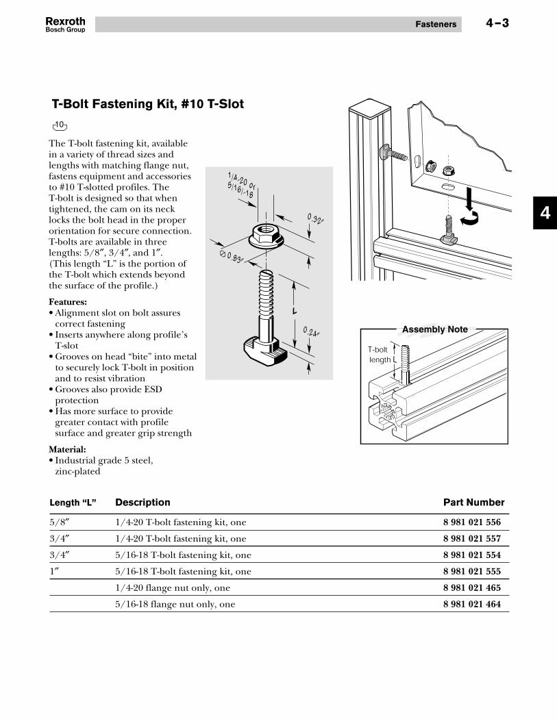
T-Bolt Fastening Kit, #10 T-Slot
The T-bolt fastening kit, availablein a variety of thread sizes andlengths with matching flange nut,fastens equipment and accessoriesto #10 T-slotted profiles. TheT-bolt is designed so that whentightened, the cam on its necklocks the bolt head in the properorientation for secure connection.T-bolts are available in threelengths: 5/8″, 3/4″, and 1″.(This length “L” is the portion ofthe T-bolt which extends beyondthe surface of the profile.)
Features:• Alignment slot on bolt assures
correct fastening• Inserts anywhere along profile’s
T-slot• Grooves on head “bite” into metal
to securely lock T-bolt in positionand to resist vibration
• Grooves also provide ESDprotection
• Has more surface to providegreater contact with profilesurface and greater grip strength
Material:• Industrial grade 5 steel,
zinc-plated
Length “L” Description Part Number
5/8″ 1/4-20 T-bolt fastening kit, one 8 981 021 556
3/4″ 1/4-20 T-bolt fastening kit, one 8 981 021 557
3/4″ 5/16-18 T-bolt fastening kit, one 8 981 021 554
1″ 5/16-18 T-bolt fastening kit, one 8 981 021 555
1/4-20 flange nut only, one 8 981 021 465
5/16-18 flange nut only, one 8 981 021 464
1/4-20 or 5/16/-18
0.32″
0.83″
0.24″
L
4–3
10

4
Aluminum Structural Framing4–4
Anti-Rotation T-Block
The Anti-Rotation T-block is usedto prevent rotation where twistmoments are applied to profileT-joints. It is available for profileswith #8 or #10 T-slots.It swivels into the T-slot and whenlocked into place with a set screw,it will prevent rotation of theadjacent profile.Includes set screw.
Features:• Swivel-in mounting• Prevents rotation at connection
point• Large surface area contact with
profile’s T-slot
Material:• Industrial grade 5 steel,
zinc-plated
Description Part Number
#8 swivel-in anti-rotation T-block, one 8 981 021 473
#10 swivel-in anti-rotation T-block, one 8 981 021 474
0.23″
0.19″0.46″
0.58″
0.24″
0.28″
0.39″
0.51″
8 10
8
10
8
10

4
Fasteners
#10 Swivel-In T-Block
The swivel-in T-block fastens loadsto any #10 T-slotted profile, evenafter the structure has been built.Its ample surface-contact area withthe profile’s T-slot provides securefastening. The swivel-in T-block canbe easily positioned, moved, andrepositioned in the T-slot. The #10swivel-in T-block is available with1/4-20, 5/16-18, and 10-32 threads.
Features:• Can be inserted anywhere
along the profile’s T-slotafter the structure is completed
• Provides quick, easy fastening• Large surface area contact
with profile’s T-slot providesmaximum strength
Material:• Industrial grade 5 steel,
zinc-plated
Description Part Number
#10 swivel-in T-block, 1/4-20, one 8 981 021 441
#10 swivel-in T-block, 5/16-18, one 8 981 021 440
#10 swivel-in T-block, 10-32, one 8 981 021 442
0.24″
0.59
″
0.79″
4–5
10
10
10
10
10

4
Aluminum Structural Framing4–6
#10 Swivel-In T-Bar
The swivel-in T-bar allows youto make fasteners to suit yourapplication. Designed for use with#10 T-slotted profiles, the T-bar issupplied as raw steel stock whichmay be cut to length, then boredand tapped in any diameter up to5/16″. The groove in the bar actsas a drill guide.Length: 39 inches.
Features:• Can drill holes anywhere along
the bar• Large surface area contact
with profile’s T-slot providesmaximum strength
Material:• 12L 14 cold drawn steel
Description Part Number
#10 swivel-in T-bar, 39 inches long, one 8 981 021 641
0.24″
0.59
″
39″
10
10
10

5
Components for Doors and Enclosures 5–1
Panel Sliders5-3
Snap-In SlidingDoor Guides
5-2
Bar Handle5-5
Lift-Off Hinges5-7
Heavy-DutyHinges
5-6
Strap Handles5-4
Section 5—Components for Doorsand Enclosures
Whether you’re looking for com-ponents to build doors or fixedenclosures, you’ll find what youneed on the following pages.
Bosch offers two basic types ofdoors that easily fit your structuralframing system: (1) sliding doorsor panels that move horizontallyor vertically within a sliding doorprofile, or (2) hinged doors that
swing open and closed. Doorand enclosure components arecompatible with all other elementsin the structural framing systemmaking it easy to enclose areas thathave already been integrated intothe system, secure work areas formaintenance or construction,or build partitions aroundworkstations for privacy.
Compact Lock5-9
Door Stops5-8
Universal BallDetent Latch
5-12
Door Seals5-13
Magnetic Latch5-10
Ball DetentLatch5-11
BOSCH
#8 Glazing Strip5-15
#10 Panel SupportInserts
5-14

5
Aluminum Structural Framing5–2
Snap-In Sliding Door Guides
Snap-in sliding door guidesprovide a track on which slidingdoors can ride. They are designedto snap easily into #10 T-slots onprofiles. The construction of theguides is suitable for light- tomedium-weight doors and panels.Hard plastic glide insert is availablethat fits into guide groove to helpdoor slide smoothly and safely.
Length: 78 inches
Features:• Can be used with all standard
structural profiles• Snap-in construction provides
quick, easy installation
Material:• Snap-in sliding door guide:
black PVC• Plastic glide insert: black
polyethylene
Description Part Number
#10 snap-in sliding door guide, 78 inches long, one 8 981 021 458
Plastic glide insert, 78 inches long, one 3 842 516 694
1.50″0.36″
0.83″
0.71″
0.31″
10
L
H
To create a removable door, set dimension "H" equal to "L"minus 7/8″
Assembly Hint
10
5
Components for Doors and Enclosures 5–3
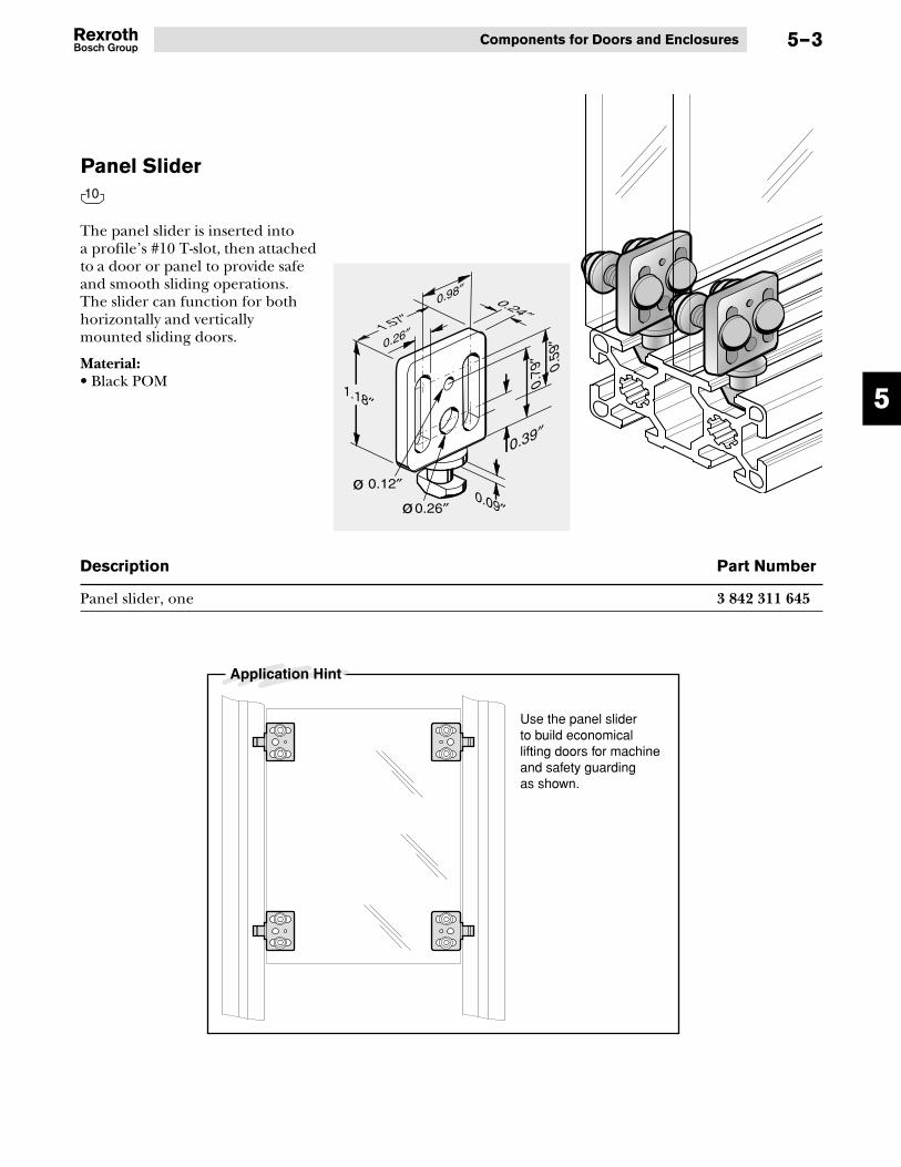
Panel Slider
Description Part Number
Panel slider, one 3 842 311 645
The panel slider is inserted intoa profile’s #10 T-slot, then attachedto a door or panel to provide safeand smooth sliding operations.The slider can function for bothhorizontally and verticallymounted sliding doors.
Material:• Black POM
Use the panel slider to build economical lifting doors for machine and safety guarding as shown.
Application Hint
0.24″
1.18″
0.09″
0.79
″0.
59″
0.39″
1.57″0.98″
0.26″
0.26″
0.12″
10

5
Aluminum Structural Framing5–4
Strap Handles
The strap handle is ideal foropening and closing sliding doorsand access panels. Its sturdy designand solid grip also make it excel-lent for material handling trays.
Material:• Black polyamide
Recommended hardware:• Medium:
1/4-20 x 5/8″ socket head capscrew
• Large:1/4-20 x 3/4″ socket head capscrew
Description Part Number
Medium strap handle, one 3 842 525 480
Medium strap handle, one 3 842 525 481
Large strap handle, one 3 842 525 766
Large strap handle, one 3 842 525 767
1.97″
1.97″
5.24″
7.68″
7.05″
4.61″
1.02″
1.02″
0.25″
0.25″
8
10
8 10
8
8
10
10
Medium
Large

5
Components for Doors and Enclosures 5–5
Bar Handle
The bar handle can be usedwith drawers and swinging andsliding doors. Handle is fastenedusing double-sided tape, rivets,or button-head cap screws.
Length: 118 inches
Material:• Natural anodized aluminum
Description Part Number
Bar handle, 118 inches long 8 981 021 642
0.98
″
0.79″ 0.08″
8 10

5
Aluminum Structural Framing5–6
Heavy-Duty Hinges
These hinges attach profiles to eachother or to panels. Three versionsare available: to attach two #8profiles, to attach two #10 profiles,or to connect #8 profiles to #10profiles.You can also attach doors thathave different size T-slots than thesupport frame. Mounting hard-ware included.
Features:• Hinge can be used for parallel
or perpendicular mountingof profiles
• Mounting hardware included
Material:• Hinge: black polyamide 6• Hinge pin: zinc-plated steel
DescriptionWhen joining Profile 1 to Profile 2 FMAX Specify this hinge part number (pkg of 2)
A – 33.5 lbs-f 8 981 021 496
B – 33.5 lbs-f 8 981 021 497
C – 33.5 lbs-f 8 981 021 498
8 10
8 8
8 10
10 10
1-3/
4"
1"
1"
1/4"
8
8 A
1-3/
4"
1"
1-3/4"
1/4"
8
101-
3/4" 1-3/4"
1-3/4"
1/4"
10
10
B
C
0.19″
Profile 1 Profile 2
FMAX
x2
x2
x2

5
Components for Doors and Enclosures 5–7
Lift-Off Hinge needed when joining Part Number (pkg of 2)
Profile 1 to Profile 2 Swing direction
A Right-hand (not shown) 8 981 021 500
B Right-hand (not shown) 8 981 021 504
C Right-hand (not shown) 8 981 021 502
A Left-hand (shown above) 8 981 021 499
B Left-hand (shown above) 8 981 021 503
C Left-hand (shown above) 8 981 021 501
Lift-off hinges are designed forhanging doors on profiles with #8or #10 T-slots. This hinge can alsobe used to hang doors that have adifferent size T-slot than thesupport frame.All mounting hardware included.
Features:• Hinges can be positioned to
provide right- or left-handopening
• For surface- or butt-mount
Material:• Hinge: black polyamide 6• Hinge pin: zinc-plated steel
Lift-Off Hinges
8 10
8 8
8 8
8 10
8 10
10 10
10 10
FMAX = 67.4 lbs.-f
0.20″0.20″
0.71″
0.45″
0.75″
1-3/
4″
1″
1″8
8
1/4″
A
2x
B
2x
C
2x
1-3/
4″
1″
8
1/4″
1-3/4″10
1-3/
4″
1/4″
1-3/4″
1-3/4″
10
10

5
Aluminum Structural Framing
Door Stops
Door stops provide a buffer forfreely swinging or sliding doorsto lessen noise and protect thedoor from damage. Three stylesare available to fit profiles with#10 T-slots: large cylindrical, smallcylindrical, and bullet-shaped.Includes installation hardware.
Material:• Rubber, hardness 55, shore A
Description Part Number
Large cylindrical stop kit, package of 10 8 981 021 578
Small cylindrical stop kit, package of 10 8 981 021 579
Bullet-shaped stop kit, package of 10 8 981 021 580
0.39″
0.79″
0.59″
0.94″
0.39″
0.75″
Ø0.79″
Ø0.79″
Ø0.79″
10
5–8

5
Components for Doors and Enclosures
Compact Lock
Compact locks are designed foruse with 1.5″-series profiles. Theyfeature a self-latching mechanismand an ergonomic, low-profilerelease handle. Locks are availablewith a universal key, with randomlyselected keys, or in a “latch only”non-locking version. Includes twokeys and mounting hardware.Some machining necessary.
Material:• Lock assembly: Die-cast zinc,
black powder-coated• Hardware: zinc-plated steel
Description Part number
A – Compact lock, with random key, one 8 981 021 561
B – Compact lock, with universal key, one 8 981 021 562
C – Compact lock, non-locking, one 8 981 021 619
1.38″
3.46″
max. 0.98″ max. 0.98″
0.04″ to 0.12″
3.15
″
2.95
″
1.5″
0.79
″
1.22
″
2.21
″
0.26
″
10
5–9
1/4-20 x 13⁄8″

5
Aluminum Structural Framing
Magnetic Latches
BOSCH
Description Part Number
9.0 lb magnetic latch , one 8 981 021 582
Magnetic latches are designedto hold swinging doors shut.The magnetic latch is designedfor use with #8 or #10 T-slottedprofiles, and has a 9 lb. pullingforce. Includes two striker plates.
Material:• black polyamide 6,
zinc-plated steel
8 10
8 10
0.33″
0.55″
1.61″1.22″
0.83″
9.0 lb. magnet
0.16″
0.21″
1.12″ 0.41″
1.38″1.89″
0.35″
0.42″
0.06″
0.55″
1.81″1.22″
0.16″
5–10

5
Components for Doors and Enclosures
Required Mounting Hardware Cap Screw Washer Square-Nut
#10-32 x 5/8″ (4x) #10 Flat (4x) #10-32 (4x)
#10-32 x 5/8″ (4x) #10 Flat (4x) #10-32 (4x)
#10-32 x 5/8″ (4x) #10 Flat (4x) #10-32 (4x)
Ball Detent Latch
Description Part Number
Ball detent latch, one 3 842 524 986
The universal ball detent providesa positive stop on sliding andswinging doors with profile framesof various sizes. The universal balldetent can also be used as a latchfor frameless doors and movableflaps. It may be mounted toprofiles with #8 or #10 T-slots, ordirectly to the door material. It ismade of conductive material andis suitable for ESD applications.
Features:• Conductive material is ESD safe• Mounts to profile or other
structural materials
Material:• Black polyamide 6, conductive
3.00″
2.91″ 2.24″
0.87″0.28″
8 10
8�8
8�10
10�10
5–11

5
Aluminum Structural Framing
Heavy-Duty Ball Detent Latch
Description Part Number
Heavy-duty ball detent latch, one 8 981 021 672
The heavy-duty ball detent latchprovides a positive stop onswinging doors with profile framesof various sizes. The ball detentlatch can also be used for framelessdoors and movable flaps. It may bemounted to profiles with #10 T-slots, or directly to the doormaterial. Includes mountinghardwarefor #10 T-slots.
Features:• Mounts to profile or other
structural materials
• Mounting hardware included
Material:• Black anodized aluminum
2.76
″
0.18
″
0.47″
0.10″
0.08″
1.97
″1.
97″
1.97
″
2.32
″2.
36″
1.18″ - 2.17″ 0.71″
3.15″ 0.18″
0.71
″
0.20
″
0.45″
0.18″
1.5″
serie
s
10
5–12

5
Components for Doors and Enclosures
Door Seals
Door seals prevent dirt, debris,and other unwanted materialsfrom entering or escaping througha closed swinging door and itsadjoining profile. Door seals areresistant to mineral oil and organicsolvents, and are available for #8and #10 T-slotted profiles.
Length: 393 inches
Material:• Black NBR (soft rubber),
hardness 60, shore A
Description Part Number
#8 door seal, 393 inches long, one 8 981 021 643
#10 door seal, 393 inches long, one 8 981 021 644
8 10
0.20
″ 0.20
″
8
8
10
10
8
10
5–13

5
Aluminum Structural Framing
Panel Support Inserts
Panel support inserts securelyfasten panels or panes from 1/8″to 5/16″ thick into #10 T-slots ofprofiles. Their sturdy designprevents panels from shiftingwithin the T-slot. Inverted, theinserts function as cover strips.When using heavy 1/4″ thickpanels or panes in the #10 T-slot,Bosch recommends using theheavy-duty panel support insert.
Length: 78 inches
Features:• Can be used with panels or panes
from 1/8″ to 5/16″ thick• Easy, snap-in installation• Can be used as panel support
insert, or invert and use ascover strip
Material:• Black polypropylene
Description Part Number
#10 panel support insert for 1/8″ to 5/16″ thick panels, 78 inches long, one 8 981 021 453
Heavy-duty #10 panel support insert for 1/4″ thick panels, 78 inches long, one 8 981 021 452
Inserts can be inverted and used ascover strips
1/4″
1/8″ to 5/16″
10
10
L2 (in.)
L1 + 0.84″
L1 + 0.63″Heavy DutyL1 L2
Panel Sizing Dimensions
10
10
10
10
10
5–14

5
Components for Doors and Enclosures
Glazing Strip
The press-in glazing stripeffectively seals the panel or panein #8 T-slots. Simple installationallows the glazing strip to beinstalled after panel assembly.For thin panels, the glazing stripcan be inserted on both sides.The glazing strip will also preventpanels from rattling in structureswhere vibration is present.
Length: 393 inches
Features:• Resistant to acid, caustic solution,
alcohol, mineral oil, and benzol.
Material:• Light gray thermoplastic
elastomer
Description Part Number
Glazing strip, 393 inches long, one 8 981 021 636
1133
2
To simplify installation:First, press the ends into the T-slot (1).Then, press the center of the Glazing Strip into the T-slot (2).Finally, working out from the center of the uninstalled portion (3) of the Glazing Strip,press the Glazing Strip into position.
8
5/64″ – 1/8″ 5/32″ – 1/4″
8
8
8
5–15

6
Aluminum Structural Framing6–0
Section 6—Floor to Frame Elements
Leveling Feet6-1 & 6-2
Leveling FootPlates for 2x2 &
3x3 Profiles6-3
Threaded Sleevefor Leveling Feet
6-3
Base Plates andAnchor Bolt
6-6
Plate-MountedCasters
6-4
Floor to frame elements ensurethat every structure you build hasa sturdy, secure foundation.The wide variety of feet, baseplates, foot plates, and castersavailable will help you level, roll, orfasten your structure to meet yourneeds. In addition, feet and casterscan be used on the shop flooror in offices, and are designedwith protective materials toprevent damage to flooring.
Die-CastFoundation
Bracket6-5

6
Floor to Frame Elements 6–1
Steel Leveling Feet
Steel leveling feet provide a sturdysupport for heavy machine framesand worktables requiring extrasupport. The threaded shaft andjam-nut allow adjustment tocompensate for uneven floorsurfaces.
The 1/4-20 version is designedfor use with 1″-series profiles,and supports up to 1000 lbs.
The 1/2-13 version is used with1.5″-series profiles, and supportsup to 5000 lbs.
Material:• Zinc-plated steel stem and nut• Steel foot with black chromatefinish
8 10
1000 lbs.
1/4-20
1.00″
1.95″1.25″
Anti-Vibration Leveling Feet
Anti-vibration leveling feet providesupport for machine frames andworktables where vibration transferis a concern, such as test stations.The threaded shaft and jam-nutallow adjustment to compensatefor uneven floor surfaces.
It is available in a 1/2-13 versionfor use with 1.5″-series profiles,with version to support up to 120lbs., 240 lbs., or 2400 lbs.
Material:
• Zinc-plated steel stem and nut• Yellow zinc-plated foot with
Anti-Vibe™ pad
10
120 lbs.
1/2-13
Anti-vibrationPad
1.88″
3.75″
2.00″
Anti-vibrationPad
2400 lbs.
1/2-13
1.88″
3.75″
2.00″
Anti-vibrationPad
240 lbs.
1/2-13
1.88″
3.75″
2.00″
5000 lbs.
1/2-13
1.88″
3.13″
2.00″
Description Part Number
Steel leveling foot, 1/4-20 x Ø1.00″, one 8 981 021 515
Steel leveling foot, 1/2-13 x Ø1.88″, one 8 981 021 517
Description Part Number
A Anti-vibration leveling foot, 120 lbs. capacity, 1/2-13 x Ø1.88″, one 8 981 021 512
B Anti-vibration leveling foot, 240 lbs. capacity, 1/2-13 x Ø1.88″, one 8 981 021 513
C Anti-vibration leveling foot, 2400 lbs. capacity, 1/2-13 x Ø1.88″, one 8 981 021 514
108
8
10
10
10
10
10

6
Aluminum Structural Framing6–2
Nylon Leveling Feet
Nylon leveling feet provide a sturdysupport for heavy machine framesand worktables requiring extrasupport. The foot pivots up to 15°and the threaded shaft and jam-nutallow adjustment to compensatefor uneven floor surfaces. Twoholes in the each foot allow thefeet to be lagged to the floor.
Four 1/2-13 versions are availablefor use with 1.5″-series profiles,with two different foot sizes andload capacities, each in standardand non-skid versions.
Material:• Zinc-plated steel stem and nut• Nylon foot• Elastomer rubber non-skid pad
10
Glider Leveling Feet
Glider leveling feet provide asupport for light-duty frames andworktables while allowing easymovement across floor surfaces.The threaded shaft and jam-nutallow adjustment to compensatefor uneven floor surfaces.
Three versions are available: a1/4-20 version for use with 1″-seriesprofiles, a 5/16-18 version for usewith the threaded sleeve shown onpage 6-3, and a 1/2-13 version foruse with 11⁄2″-series profiles.
Material:• Zinc-plated steel stem and nut• Zinc-plated foot with nylon glider
8 10
Description Part Number
Nylon leveling foot, standard, 1/2-13 x Ø1.97″, one 8 981 021 519
Nylon leveling foot, with non-skid pad, 1/2-13 x Ø1.97″, one 8 981 021 520
Nylon leveling foot, standard, 1/2-13 x Ø3.15″, one 8 981 021 521
Nylon leveling foot, with non-skid pad, 1/2-13 x Ø3.15″, one 8 981 021 522
10
10
Description Part Number
Glider leveling foot, 1/4-20 x Ø1.2″, one 8 981 021 523
Glider leveling foot, 5/16-18 x Ø1.2″, one 8 981 021 524
Glider leveling foot, 1/2-13 x Ø2.8″, one 8 981 021 525
8
8 10
10
10
10
1/4-20
250 lbs.
1.20″
2.25″1.50″
Glider
250 lbs.
1.20″
2.25″1.50″
Glider
5/16-181/2-13
2.80″
3.03″
2.00″
500 lbs.
Glider
1/2-13
1.97″
4.37″
3.00″
15° 15°
4000 lbs.
1/2-13
3.15″
4.37″
3.00″
15° 15°
5000 lbs.
1/2-13
1.97″
4.37″
0.125″
3.00″
15° 15°
800 lbs.
Non-skid Pad Non-skid
Pad
1/2-13
3.15″
4.37″
0.125″
3.00″
15° 15°
1800 lbs.

6
Floor to Frame Elements 6–3
Threaded Sleeve for Leveling Feet
The press-fit threaded sleeveallows the use of leveling feet witha 5/16-18 shaft with 1.5″-seriesprofiles. A 37/64″ hole is drilledthrough the profile and thethreaded sleeve is press-fitinto place.
Machining Required:• 37/64″ through-hole
Material:• Zinc-plated steel
Description Part Number
Threaded sleeve, one 8 981 021475
10
Leveling Foot Plate Kit(for use with 2 x 2 and 3 x 3 profiles)
This leveling foot plate is used forleveling feet with 1/2-13 shaftsand is available to fit 2x2 or 3x3profiles. It is equipped witha threaded center hole toaccommodate the leveling foot.Mounting hardware included.
Machining Required:• 2x2 profiles: Corner holes
tapped 1/4-20
• 3x3 profiles: Corner holestapped 1/2-13
Material:• Foot Plate: 6061 aluminum• Hardware: zinc-plated steel
Description Part Number
Leveling foot plate kit for 2x2 profiles, one 8 981 021 584
Leveling foot plate kit for 3x3 profiles, one 8 981 021 585
8 10
Ø0.75″
1.08″
0.08″
Ø37⁄64″
5⁄16-18
0.62″0.50″
or
2″or3″
2″ or 3″
5/16-18or1/2-13
1/4-20 or
1/2-13

6
Aluminum Structural Framing6–4
Plate-Mounted Casters
Plate-mounted casters are used forrolling heavy loads on shop floors.Two styles available: swivel withlocking mechanism and fixed.Both styles are available with eithera 3.94″ or 4.92″ diameter wheel.Mounting hardware sets must beordered separately.
Material:• Wheel: black plastic• Plate housing: zinc-plated steel
Wheel Type Wheel Dia. Height Force Part Number,D (in.) h (in.) a b (lbs.) One
A Swivel with lock 3.94″ 4.92″ 4.92″ 1.57″ 135 3 842 259 790
B Fixed 3.94″ 4.92″ 135 3 842 259 792
A Swivel with lock 4.92″ 5.91″ 130 1.57″ 200 3 842 259 791
B Fixed 4.92″ 5.91″ 200 3 842 259 793
C Caster mounting hardware kit, one (order one kit per caster) 8 981 021 560
10
A
B
Dimensional Information
CSTOP
2.36
″2.
17″
3.34
″
3.94″
3.00″3.15″
0.34″ x 0.47″
F
F

6
Floor to Frame Elements 6–5
Description Qty Part Number
Foundation bracket with fasteners 1 8 981 021 605
5/16″ anchor bolt, L=21⁄2″, one 1 8 981 021 360
Die-cast Foundation Bracket
Die-cast foundation brackets fastenany structural profile with #10T-slots to a floor, deck, or shippingskid. It is shaped so that it does notinterfere with the leveling foot.
5/16-18 x 1″T-Bolt Kit
0.37″
0.91″ 1.10″ 1.50″2.52″2.97″
0.39″
6.12
″
0.91
″
5.75
″4.
21″
2.68
″0.
91″
0.91
″
Anchor Bolts
Material:• Die-cast aluminum• Hardware: zinc-plated steel
10
10
L
Ø5/16″
11⁄8″ min.
Ø5/16″
6- 8 lb-ft

6
Aluminum Structural Framing6–6
Base Plates and Anchor Bolts
The base plate and anchor boltprovide a stable foundation forprofiles. Two sizes are available:1.5″ x 1.5″ and 3″ x 3″.The anchor bolts can be usedwith either base plate to securethe plate to the floor. Two lengthsof 5/16″ anchor bolts are available:2″ and 3″.
Material:• Base plates: machined aluminum,
anodized• Anchor bolts: zinc-plated steel
Description Part Number
1.5x1.5 base plate, one 8 981 021 486
3x3 base plate, one 8 981 021 487
5/16″ anchor bolt, L=21⁄2″, one 8 981 021 360
10
Anchor Bolt
Base Plate
Anchor Bolt
Base Plate
1.75″
3/8″
0.50
″
1.75″3.25″
0.50″
3.50″
4.00″
5.00″
2.50″
3/8″0.
50″
L
Ø5/16″
11⁄8″ min.
Ø5/16″
6- 8 lb-ft
Anchor Bolts

7
Finishing Elements and Accessories 7–1
Section 7—Finishing Elementsand Accessories
T-Slot Covers7-3
End Caps forStructural Profiles
7-2
End caps and T-slot covers helpyou enhance safety, as well as give aclean, finished appearance to youraluminum framing structure.A variety of accessories, suchas swivel brackets and lockinglevers, open a wide range of newpossibilities for your structures.
AluminumT-Slot Covers
7-4
Swivel Bracket7-6
Locking Lever7-5
R-A-M® Mount7-7

7
Aluminum Structural Framing7–2
End Caps for Structural Profiles
L2
L1L3
End caps give your structure aclean, finished appearance.
Features:Easy installation, no tools required
Material:Standard version: polyamide 6
8 10
Square/Rectangular End CapsProfile used with Thickness (in.) Color Part Number, OneL1 L2 L3
1″ x 1″ 1/8″ Black 8 981 021 430
1″ x 2″ 1/8″ Black 8 981 021 431
2″ x 2″ 1/8″ Black 8 981 021 432
1.5″ x 1.5″ 3/16″ Black 8 981 021 433
1.5″ x 3″ 3/16″ Black 8 981 021 434
3″ x 3″ 3/16″ Black 8 981 021 435
L2
L1
L3
Profile used with Thickness (in.) Color Part Number, One
L1 L2 L3
1″ x 1″ with 1/4″ hole 1/8″ Black 8 981 021 436
1.5″ x 1.5″ with 1/2″ hole 3/16″ Black 8 981 021 437
End Caps with Holes
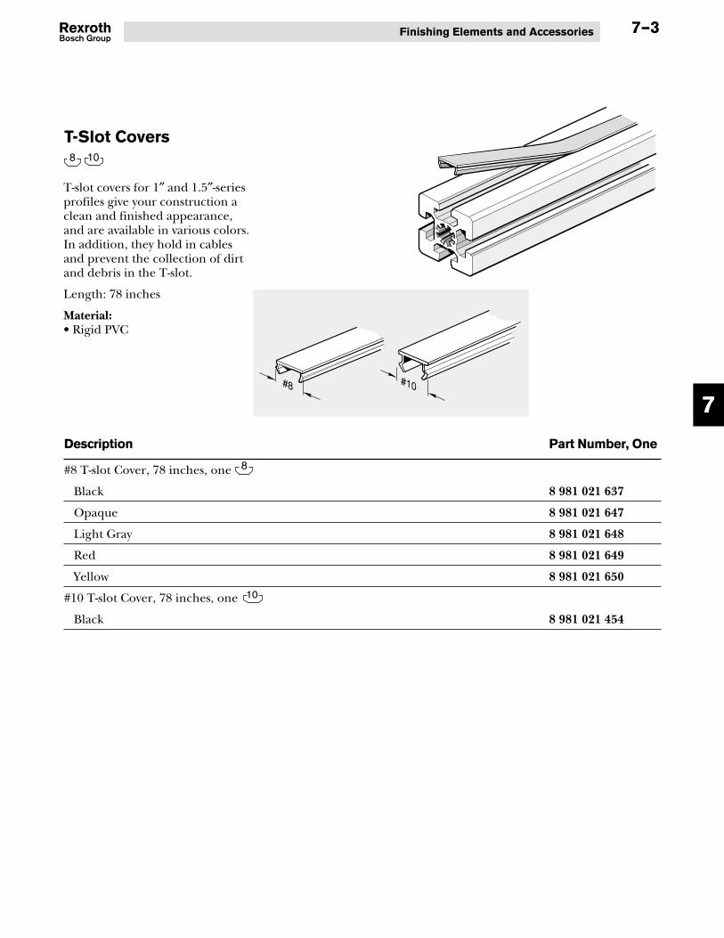
7
Finishing Elements and Accessories 7–3
T-Slot Covers
Description Part Number, One
#8 T-slot Cover, 78 inches, one
Black 8 981 021 637
Opaque 8 981 021 647
Light Gray 8 981 021 648
Red 8 981 021 649
Yellow 8 981 021 650
#10 T-slot Cover, 78 inches, one
Black 8 981 021 454
T-slot covers for 1″ and 1.5″-seriesprofiles give your construction aclean and finished appearance,and are available in various colors.In addition, they hold in cablesand prevent the collection of dirtand debris in the T-slot.
Length: 78 inches
Material:• Rigid PVC
8 10
8
10
#8 #10

7
Aluminum Structural Framing7–4
Aluminum T-Slot Cover
Description Part Number, One
#8 Aluminum T-slot cover, 78 inches long, one 8 981 021 638
#10 Aluminum T-slot cover, 78 inches long, one 8 981 021 639
Aluminum cover strip matchesprofile. Provides a finished lookto all profiles and can be used tosecure cables and protect theT-slot against the accumulationof dirt and dust. Also perfect forclean room applications.
Length: 78 inches
Material:• Natural anodized aluminum
8 10
8
10
#10
#8

7
Finishing Elements and Accessories 7–5
Locking Lever
Description Stem Length Height Handle Length Part NumberS H L
Locking lever 1/4-20, one 0.50″ 1.26″ 1.65″ 8 981 021 364
Locking lever 1/4-20, one 0.75″ 1.26″ 1.65″ 8 981 021 365
Locking lever 5/16-18, one 0.50″ 1.69″ 2.48″ 8 981 021 366
Locking lever 5/16-18, one 0.75″ 1.69″ 2.48″ 8 981 021 367
The locking lever can be used onmulti-angle fasteners to providequick and easy angle changes.Use with #10 T-blocks or#10 T-nuts. Locking levers areavailable in two lengths: 1.65″ and2.48″.
Material:• Lever: die-cast zinc• Spindle: pressure die-cast zinc• Stem: zinc-plated steel
Locking Lever
S
LH
1/4-205/16-18
10

7
Aluminum Structural Framing7–6
Swivel Bracket
The swivel bracket is designedfor shelves which need to bepositioned at various angles up to180°. Connection kit includesmounting hardware. For lockinglever, see page 7-5. Mmax = 9 lbs.
Material:• Bracket: zinc-plated steel• Mounting hardware:
zinc-plated steel
Description Part Number, One
Swivel bracket only 3 842 516 705
#10 Swivel bracket connection kit 8 981 021 559
10
10
Fixed
OR
Movable
3.94
″
5.12
″
R=2.56″
R=1
.97″
0.25
″
0.59
″
0.30″
0.10″
0.89″1.18″
0.32″
0.32″
Order 5/16-18 x 0.50″ lockinglever (8 981 021 366)separately on page 7-5.

7
Finishing Elements and Accessories 7–7
R-A-M® Mount
The R-A-M® mount provides a fullyadjustable, two-joint connectionbetween two surfaces. Lockinghandle secures the R-A-M® mountonce the desired position isreached. Perfect for fixturingor adjustable equipment mounts.
Order T-Bolt fasteningkit separately.
Material:• Mounting plates and R-A-M®
mount body: black die-castaluminum
• Hardware: stainless steel• Adjustment balls: rubber
Description Part Number
R-A-M® mount, one 8 981 019 573
5/16-18 x 3/4″ T-bolt fastening kit, one 8 981 021 554
10
3.31″
7.64″

8
Aluminum Structural Framing8–0
Section 8—Tools
With Bosch aluminum structuralframing, you can either specifyprofiles square cut to length andwith the ends machined to meetyour needs . . . or you can cutand finish the ends yourself usingBosch tools described on thefollowing pages. In this section,you can select the correct specialdrills, drilling templates, threadtaps, and wrench sets needed tocomplete the job quickly andwith precise fits.
Thread Taps8-1
Drill Bits8-2
How to CutProfiles
8-1
#10 Drilling andBoring Jig
8-3
Ball PointL-Wrenches
8-5
Cleaning Block8-5
DO NOT predrill or tap when usingself-tapping screws.
Thread Size Tap Size
1/4-20 1/4-20
5/16-18 5/16-18
1/2-13 1/2-13
TAP/DRILLSPECIFICATIONS
#10 Miter DrillingJigs8-4
#8 Drilling andBoring Jig
8-3

8
Tools 8–1
How to Cut Profiles
Thread Taps
To cut profiles to the desiredlength virtually burr-free:
Cutting blade selection:Use a metal 14-inch diametercircular saw blade that is 1/8″or 3/32″ wide, and that has 92carbide-tipped teeth.
Cutting speed:(1) For production cutting, the
saw cutting rate should beapproximately 90 ft. perminute (maximum).
(2) The saw blade rotation speedshould be approximately2500 RPM.
These thread taps form threads onthe center bore of profiles. Do notuse taps when using self-tappingconnection screws.
Taps are available in two sizes:• 1/4-20, for use with profiles with
#8 T-slots• 1/2-13, for use with profiles with
#10 T-slots
Description Part Number
1/4-20 thread tap for 1″-series profiles, one 8 981 021 569
1/2-13 thread tap for 1.5″-series profiles, one 8 981 021 570
8 10
1/2-13
Ø 7/16″1/4-20
Ø 3/16″

8
Aluminum Structural Framing8–2
Twist Drill
Description Part Number
Ø5/16″ x 63⁄8″ long drill bit, one 8 981 021 574
Ø3/8″ x 63⁄4″ long drill bit, one 8 981 021 573
Ø33/64″ x 8″ long drill bit, one 8 981 021 571
Ø37/64″ x 83⁄4″ long drill bit, one 8 981 021 572
Use these drill bits to createthrough-holes and access holesin profiles that correspond tothe standard sizes recommendedfor the various fasteners andconnectors. Features a 118° point.
Four sizes are available:• Ø5/16″ x 63⁄8″ long• Ø3/8″ x 63⁄4″ long• Ø33/64″ x 8″ long• Ø37/64″ x 83⁄4″ long
Material:L
Ø
Ø
• Treated high speed steel,black oxide finish

8
Tools 8–3
#8 Drill and Boring Jig
Description Part Number
Drill and boring jig for #8 T-slots, one 8 981 021 428
These jigs provide fast, easypositioning of 33/64″ or 5/16″holes in profiles with #8 T-slots.The jigs lock into position withthe twist handle.
8
#10 Drill and Boring Jig
Description Part Number
Drill and boring jig for #10 T-slots, one 8 981 021 429
These jigs provide fast, easypositioning of 33/64″ or 5/16″holes in profiles with #10 T-slots.The jigs lock into position withthe twist handle.
10
0.75″0.50″
8
Ø33/64″
Ø5/16″
0.97″0.75″
10
Ø37/64″
Ø3/8″

8
Aluminum Structural Framing8–4
#10 Miter Drilling Jigfor End-to-End Variable Angle Connectors
Description Part Number
#10 miter drilling jig for end-to-end variable angle connectors, one 8 981 021 576
This jig provides the proper endspacing when drilling 37/64″ holesin profiles with #10 T-slots thathave up to a 45° mitered endfinish. Use this drilling jig whenassembling profiles using end-to-end variable angle connectors.
#10 Miter Drilling Jigfor End-to-Side Variable Angle Connectors
Description Part Number
#10 miter drilling jig for end-to-side variable angle connectors, one 8 981 021 597
This jig provides the proper endspacing when drilling 37/64″ holesin profiles with #10 T-slots thathave up to a 45° mitered endfinish. Use this drilling jig whenassembling profiles using end-to-side variable angle connectors.
37/64″
0.89″
37/64″
0.97″

8
Tools 8–5
Ball Point L-Wrenches
Description Part Number
1/8″ ball point L-wrench, one 8 981 021 564
5/32″ ball point L-wrench, one 8 981 021 563
9/64″ ball point L-wrench, one 8 981 021 565
3/16″ ball point L-wrench, one 8 981 021 566
1/4″ ball point L-wrench, one 8 981 021 577
5/16″ ball point L-wrench, one 8 981 021 567
T-30 Torx ball point L-wrench, one 8 981 021 568
Ball point L-wrenches are availablein a number of sizes to fit commonhex-socket head screws. A T-30Torx version is also available.
Cleaning Block
Description Part Number
Cleaning block, one 3 842 518 650
This block is used to remove dirtmarks and small scratches fromprofiles and other anodizedsurfaces. Made of an elastic-basedmaterial impregnated with fineabrasives. Very long-lasting.

9
Aluminum Structural Framing9–0
Section 9—Engineering Data and Specifications
Technical data
Material designation according to DIN (ISO) for Bosch profiles 6063 T6
Material number according to DIN (ISO) 6063 T6
Tensile strength (expected) Rm = 36,000 lb./in.2
0.2% proof stress (expected) Rp0,2 = 29,000 lb./in2
Elongation at rupture A5 or A10 A5 = 10%A10 = 8%
Modulus of elasticity E E = 10x106 lb./in2
Brinell hardness 75 HB
Coefficient of linear expansion α(-58°...+68°F) = 12.1 x 10⁻⁶in/in/°Fα(+68°...+212°F) = 13.0 x 10⁻⁶in/in/°F
Poisson’s ratio µ = 0.34
Anodizing process–layer thickness–layer hardness R204-(.0003 in-300HV)

9
Engineering Data and Specifications 9–1
Dimension tolerance tol [in.] for profiles from different shipments
AT
Aø
T ± tol
A
0.319
8 10
T ± tol ±0.006 ±0.006ø 0.226
0.2260.394
0.394
1.0±0.006″
1.5±0.008″
2.0±0.010″
3.0±0.012″
6.0±0.016″± tol
+0.008 - 0.000 0.394 +0.016- 0.000
224″
±0.002
±0.002
max
. 0.
018″
max.0.060″
L = 78″
11.81
1″
max
. 0.0
60″
L = 78″
Average accuracy [in.] within a profile bar
Lengthwise profile straightness tolerance
Torsional tolerance in the lengthways direction of the profile

9
Aluminum Structural Framing9–2
L
FF F
f
f f
1 2 3
Bending deflection
Profile bending deflection for static load cases �➁�from force F.
Profile bending deflection from the profile’s own weight
Determination of maximum occurring bending stress
E = Young’s modulus = 10x106 lb/in2
f� = FL3
3E Iin
f➁ = FL3
48E Iin
f� = FL3
192E Iin
f� = FL3
8E Iin
f➁ = 5FL3
384E Iin
f� = FL3
384E Iin
σ� = FL
Win
σ➁ = FL
4Win
σ� = FL
8Win
Force = F (lb.)Amount of Deflection = f (in.)
Length of Profile = L (in.)Inertia = I (in.4)
Section Modulus = W (in.3)
σmax = maximumallowable bendingstress = 28,000 lb/in2

9
Engineering Data and Specifications
Load Carrying Capacity
The tables list the recommended torqueand maximum load carrying capacity ofthe structural framing connectors.Exceeding any of the published maximumvalues may cause permanent deformationof the profile T-slot or connector. As withany structural design, it is critical toconsider all legal and technical safetyrequirements. This data supersedes allprevious published data and we reservethe right to make technical changeswithout notice.
Fmax Fmax Fmax
T-slot load carrying capacities
T-bolt and T-nut ConnectionScrew
Swivel-inT-Block
3″ x 6″
3″ x 3″
8
8
8
10
10
10
10
10
10
= 1574 lbs = 2248 lbs = 2023 lbsFmax Fmax Fmax
= 899 lbs = 1124 lbs = 495 lbs Fmax Fmax Fmax
1″ x 1″
2″ x 2″
1.5″ x 1.5″
1.5″ x 1.5″H
1.5″ x 3″
1.5″ x 3″H
1″ x 2″
9–3

9
Aluminum Structural Framing
1″ x 1″
44 lb-in
44 lb-in
44 lb-in
221 lb-in
221 lb-in
221 lb-in
8
8
8
10
10
10
1″ x 2″
2″ x 2″
1.5″ x 1.5″
1.5″ x 3″
3″ x 3″
FmaxMmaxMmax Mmax
281 lbs 221 lb-in 664 lb-in
562 lbs 885 lb-in 1505 lb-in 221 lb-in
531 lb-in
674 lbs 531 lb-in 1416 lb-in
674 lbs 486 lb-in 1283 lb-in
1349 lbs 1593 lb-in 3540 lb-in
2284 lbs 2273 lb-in 5995 lb-in
309 lb-in
1449 lb-in
-
-
(± 5%)
Load carrying capacities of gussets
9–4
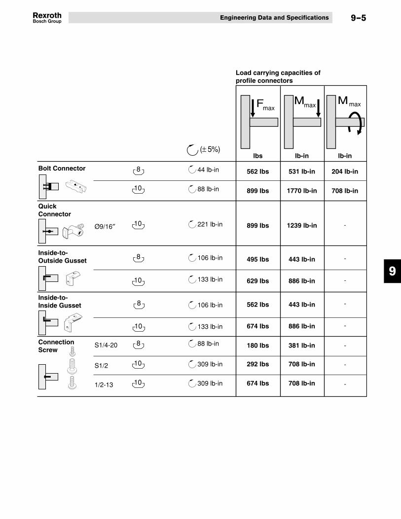
9
Engineering Data and Specifications
562 lbs
899 lbs
531 lb-in
1239 lb-in
204 lb-in
708 lb-in
899 lbs
495 lbs 443 lb-in
629 lbs
180 lbs
292 lbs
381 lb-in
708 lb-in
886 lb-in
-
FmaxMmax Mmax
10
10
10
8
8
8
Bolt Connector
QuickConnector
Inside-to-Outside Gusset
Inside-to-Inside Gusset
ConnectionScrew
44 lb-in
88 lb-in 1770 lb-in
10 309 lb-inS1/2
674 lbs 708 lb-in10 309 lb-in1/2-13
221 lb-inØ9/16″
lbs lb-in lb-in
106 lb-in
133 lb-in
106 lb-in
133 lb-in
88 lb-inS1/4-20
-
-
562 lbs 443 lb-in
674 lbs 886 lb-in
-
-
-
-
-
Load carrying capacities of profile connectors
(± 5%)
10
8
9–5

9
Aluminum Structural Framing
8
8
T-Nuts
T-Bolts
Swivel-In T-Blocks
Description Torque
Connection Screws
44 lb-in
44 lb-in
#10-32 T-Nut
1/4-20 T-Nut
#8-32 T-Nut
#10-32 T-Nut10
44 lb-in
44 lb-in
1/4-20 T-Nut
5/16-18 T-Nut
88 lb-in
221 lb-in
10 309 lb-inS1/2 x 1.2″ Self-Tapping Connection Screw
10 309 lb-in1/2-13 x 1.25″ Connection Screw
88 lb-inS1/4-20 x 0.75″ Self-Tapping Connection Screw
(± 5%)
10
10
1/4-20 T-Bolt Kit
5/16-18 T-Bolt Kit
88 lb-in
221 lb-in
1/4-20 Swivel-In T-Block
5/16-18 Swivel-In T-Block
44 lb-in
88 lb-in
#10-32 Swivel-In T-Block
221 lb-in
9–6

10
Part Number Page Part Number Page Part Number Page
Product Part Numbering Index
Section 10—Product Part Numbering Index
3842259790 6-4
3842259791 6-4
3842259792 6-4
3842259793 6-4
3842311645 5-3
3842516705 7-6
3842518650 8-5
3842524986 5-11
3842525480 5-4
3842525481 5-4
3842525766 5-4
3842525767 5-4
3842532163 3-2
3842532165 3-3
3842532167 3-3
3842532169 3-4
3842532171 3-4
3842532173 3-5
8981019573 7-7
8981021321 4-1
8981021322 4-1
8981021360 6-5
8981021364 7-5
8981021365 7-5
8981021366 7-5
8981021367 7-5
8981021375 3-19
8981021376 3-18
8981021377 3-17
8981021378 3-19
8981021379 3-19
8981021380 3-21
8981021381 3-21
8981021382 3-19
8981021383 3-20
8981021384 3-18
8981021385 3-20
8981021386 3-22
8981021387 3-22
8981021389 2-2
8981021390 2-3
8981021391 2-4
8981021392 2-5
8981021393 2-6
8981021394 2-7
8981021395 2-8
8981021396 2-9
8981021397 2-10
8981021398 2-2
8981021399 2-3
8981021400 2-4
8981021401 2-5
8981021402 2-6
8981021403 2-7
8981021404 2-8
8981021405 2-9
8981021406 2-10
8981021428 8-3
8981021429 8-3
8981021430 7-2
8981021431 7-2
8981021432 7-2
8981021433 7-2
8981021434 7-2
8981021435 7-2
8981021436 7-2
8981021437 7-2
8981021440 4-5
8981021441 4-5
8981021442 4-5
8981021443 4-2
8981021444 4-2
8981021445 4-2
8981021446 4-2
8981021447 4-2
8981021452 5-14
8981021453 5-14
8981021454 7-3
8981021458 5-2
8981021460 4-1
8981021461 4-1
8981021462 3-8
8981021463 3-10
8981021464 4-3
8981021465 4-3
8981021473 4-4
8981021474 4-4
8981021475 6-3
8981021486 6-6
8981021487 6-6
8981021488 3-16
8981021496 5-6
8981021497 5-6
8981021498 5-6
8981021499 5-7
8981021500 5-7
8981021501 5-7
8981021502 5-7
8981021503 5-7
10–1

10
Part Number Page Part Number Page Part Number Page
Aluminum Structural Framing10–2
8981021504 5-7
8981021512 6-1
8981021513 6-1
8981021514 6-1
8981021515 6-1
8981021517 6-1
8981021519 6-2
8981021520 6-2
8981021521 6-2
8981021522 6-2
8981021523 6-2
8981021524 6-2
8981021525 6-2
8981021537 3-2
8981021538 3-3
8981021539 3-3
8981021540 3-4
8981021541 3-4
8981021542 3-5
8981021547 3-16
8981021554 4-3
8981021554 7-7
8981021555 4-3
8981021556 4-3
8981021557 4-3
8981021559 7-6
8981021560 6-4
8981021561 5-9
8981021562 5-9
8981021563 8-5
8981021564 8-5
8981021565 8-5
8981021566 8-5
8981021567 8-5
8981021568 8-5
8981021569 8-1
8981021570 8-1
8981021571 8-2
8981021572 8-2
8981021573 8-2
8981021574 8-2
8981021576 8-4
8981021577 8-5
8981021578 5-8
8981021579 5-8
8981021580 5-8
8981021582 5-10
8981021584 6-3
8981021585 6-3
8981021597 8-4
8981021601 3-12
8981021602 3-12
8981021603 3-14
8981021604 3-15
8981021605 6-5
8981021606 3-6
8981021607 3-6
8981021608 3-7
8981021609 3-7
8981021610 3-7
8981021619 5-9
8981021636 5-15
8981021637 7-3
8981021638 7-3
8981021639 7-3
8981021640 5-2
8981021641 4-6
8981021642 5-5
8981021643 5-13
8981021644 5-13
8981021645 3-9
8981021646 4-1
8981021647 7-3
8981021648 7-3
8981021649 7-3
8981021650 7-3
8981021661 3-11
8981021662 3-11
8981021663 3-11
8981021664 3-11
8981021667 3-13
8981021668 3-13
8981021671 4-1
8981021672 5-12
8981992318 2-2
8981992319 2-2
8981992320 2-2
8981992321 2-2
8981992322 2-2
8981992323 2-2
8981992324 2-3
8981992325 2-3
8981992326 2-3
8981992327 2-3
8981992328 2-3
8981992329 2-3
8981992330 2-3
8981992332 2-4
8981992333 2-4

10
Part Number Page Part Number Page Part Number Page
Product Part Numbering Index 10–3
8981992334 2-4
8981992335 2-4
8981992336 2-4
8981992337 2-4
8981992338 2-5
8981992339 2-5
8981992340 2-5
8981992341 2-5
8981992342 2-5
8981992343 2-5
8981992344 2-5
8981992345 2-5
8981992346 2-5
8981992347 2-6
8981992348 2-6
8981992349 2-6
8981992350 2-6
8981992351 2-6
8981992352 2-6
8981992353 2-6
8981992354 2-6
8981992355 2-6
8981992356 2-7
8981992357 2-7
8981992358 2-7
8981992359 2-7
8981992360 2-7
8981992361 2-7
8981992362 2-7
8981992363 2-7
8981992364 2-7
8981992367 2-7
8981992368 2-8
8981992369 2-8
8981992370 2-8
8981992371 2-8
8981992372 2-8
8981992373 2-8
8981992374 2-8
8981992375 2-8
8981992376 2-8
8981992379 2-8
8981992380 2-9
8981992381 2-9
8981992382 2-9
8981992383 2-9
8981992384 2-9
8981992385 2-9
8981992386 2-9
8981992387 2-9
8981992388 2-9
8981992389 2-10
8981992391 2-10
8981992393 2-10
8981992394 2-10
8981992396 2-10
8981992397 2-10
8981992399 2-10
8981992400 2-2
8981992401 2-2
8981992402 2-3
8981992403 2-3
8981992404 2-4
8981992405 2-4

10
Part Number Page Part Number Page Part Number Page
Aluminum Structural Framing10–4
Quick ChartsQuick Conversion Chart
Fraction Decimal
1/16 0.0631/8 0.1253/16 0.1881/4 0.255/16 0.3133/8 0.3757/16 0.4381/2 0.509/16 0.5635/8 0.625
11/16 0.6883/4 0.75
13/16 0.8137/8 0.875
15/16 0.938
English/Metric Conversion Chart
Multiply By To Get
Linear Millimeters (mm) .03937 InchesInches 25.4 Millimeters (mm)
Area Millimeters2 (mm2) .00155 Inches2
Inches2 645.16 Millimeters2 (mm2)Volume Centimeters3 (cm3) .06102 Inches3
Inches3 16.387 Centimeters3 (cm3)Inches3 .0164 LitersLiters 61.024 Inches3
Velocity Meters/Minute 3.281 Feet/MinuteFeet/Minute .3048 Meters/Minute
Force Kilograms-f (kgf) 9.807 Newtons (N)Newtons (N) .10194 Kilograms-f (kgf)Pounds-f 4.448 Newtons (N)Newtons (N) .2248 Pounds-f
Pressure Bar 14.5 PSIPSI .069 Bar
Torque Newton-Meters (Nm) 8.851 Pounds-InchesPound-Inches .11298 Newton-Meters (Nm)
Moment of Inertia Centimeters4 (cm4) .02403 inch4 (in4)Inches4 (in4) 41.623 centimeters4 (cm4)

Bosch Rexroth CorporationCorporate Headquarters5150 Prairie Stone ParkwayHoffman Estates, IL 60192-3707Telephone (847) 645-3600Facsimile (847) 645-6201
Bosch Rexroth CorporationIndustrial Hydraulics2315 City Line RoadBethlehem, PA 18017-2131Telephone (610) 694-8300Facsimile (610) 694-8467
Bosch Rexroth CorporationElectric Drives and Controls5150 Prairie Stone ParkwayHoffman Estates, IL 60192-3707Telephone (847) 645-3600Facsimile (847) 645-6201
Bosch Rexroth CorporationPneumatics1953 Mercer RoadLexington, KY 40511-1021Telephone (859) 254-8031Facsimile (859) 281-3491
Bosch Rexroth CorporationMobile Hydraulics1700 Old Mansfield RoadWooster, OH 44691-0394Telephone (330) 263-3300Facsimile (330) 263-3333
Printed in the United States8981 500 308 3/03
Bosch Rexroth CorporationLinear Motion andAssembly Technologies816 E. Third StreetBuchanan, MI 49107Telephone (269) 695-0151Facsimile (269) 695-5363www.boschrexroth-us.com