Embed Size (px)
Citation preview
INCINERATING SEWAGE SLUDGE AND PRODUCING
REUSABLE ASH: JAPANESE EXPERIENCE
TAKESHIOKUFUJI Takuma Co. Ltd.
Osaka, Japan
ABSTRACT
A municipal sewage sludge incineration system consisting of a steam dryer and a step grate sludge incinerator has high efficiency. The system incinerates dewatered sludge without supplementary fuel when the water content is 78-80% and the combustible matter content is 65% or more. Most of the ash discharged from the step grate sludge incinerator is bottom ash (98%) and is semi-molten.
In Japan, two 150 wet metric tons per day (tpd) (1 65 tons) step grate sludge incinerators are installed in Kyoto City and two 100 tpd (110 tons) same type incinerators are installed in Sapporo City. Being discussed in this writing are the characteristics, reusing cases, and test results of ash discharged from the same type of incinerators.
INTRODUCTION
The quantity of dewatered municipal sewage sludge generated annually in Japan in the later half of 1980's is about four million wet t ( 4.4 million tons). Roughly half of it is incinerated. The main purpose of incineration is to reduce the weight and volume of the sludge and to stabilize and render the sludge harmless. On the other hand, tasks imposed on sludge incineration are to reduce treatment and disposal costs, energy con-
37
sumption, and the strict control of the pollution from gas and ash emitted from the incinerator.
The maximum utilization of energies in the incineration system is an effective method for reducing the treatment costs. Key points of effective energy utilization are: (a) the minimization of heat loss in the incineration thermal processes, and (b) the maximization of recovery of waste heat generated by incineration.
Conventional sludge incineration systems mostly charge dewatered sludge directly into the incinerator and then dry and bum the sludge in the incinerator. The conventional systems have an advantage of simplified construction. They, however, have the following disadvantages from a standpoint of energy consumption. They mostly require supplementary fuel oil to maintain stable combustion. A great amount of water contained in sludge is heated to steam causing a considerable loss of heat. Stable combustion is difficult to control. The combustion air ratio tends to be high.
Recent tendencies are to add a dewatered sludge drying process for the pretreatment of sludge to improve the above mentioned disadvantages in the thermal energy aspect and also to recover and use waste heat to generate steam for supplying heat energy to the sewage treatment plant (to heat, for instance, the digestion tanks), generating electric power, etc.
Though dewatered sludge is reduced and stabilized,
100r------------------------------------,
80 �---------------------• .------.. ----� III k o ... '" � 60 �I------�----�.-----�.-----�----� 0::: .... u !l • Hulti-heath: ... incinerator o 40 �I------�------�----�._----�----� IlTI Fluidized bed k Q/
.0 �
Z ii incinerator
� Rotary kiln
20 !-.-I-----j.._--_arn---- . I---.:'t---.,
Ih. In. h. Ih !�l incinerator
D Step grate incinerator
III Other
o 1978 1979 1980 1981 1982
FIG. 1 NUMBER OF INCINERATORS BY TYPE
the disposal of the ash is a big problem in cities where it is not easy to secure places for the final landfill of the ash. The effective use of ash will be an important issue of research.
SLUDGE DISPOSAL AND INCINERATORS IN
JAPAN [1]
The amount of cake incinerated has been increasing every year and the quantity incinerated in 1982 was about 1.9 million m 3 (67 million fe). Dewatered cake incineration is an effective method of sludge volume reduction and stabilization and will be increasingly adopted because of difficulty in acquiring landfill places when situations in Japan are taken into consideration.
The following types of incinerators are mostly em-ployed for sludge incineration.
(a) Vertical multiple-hearth incinerator. (b) Fluidized bed incinerator. (c) Rotary kiln incinerator. (d) Step grate incinerator. The number of each type incinerators installed in
Japan is given in Fig. 1 in the aggregate. The average daily capacity of one multiple-hearth
incinerator and one step grate incinerator is about 100 wet t (110 tons) and that of one fluidized bed incinerator is about 50 wet t (55 tons). The maximum daily capacity of one multiple-hearth incinerator is 300 wet t (330 tons) and that of one fluidized bed incinerator and one step grate incinerator is 150 wet t (165 tons).
38
The number of fluidized bed incinerators and step grate incinerators have been increasing for the following reasons:
(a) Relatively small capacity incinerators are required as it becomes difficult to acquire sludge landfill places even in local cities.
(b) The intermittent operation of the concerned incinerators is easier than that of the multiple-hearth incinerator.
(c) They do not require special odor control because the odor concentration in the flue gas is considerably lower than that of the multiple-hearth incinerator.
CONCEPTS OF SLUDGE INCINERATION
SYSTEM
There are two basic concepts for sludge incineration systems. One is based on a system in which dewatered cake is dried and then fed to an incinerator (drying I incineration system) and the other on a system in which dewatered cake is directly fed to an incinerator (direct incineration system).
We have adopted a dryinglincineration system designed according to the water content of dewatered cake to be treated with first consideration given to improvement of heat recovery rate and stabilization of combustion. The disadvantage of the direct incineration system are described as follows:
(a) Direct feeding of higher water content cake to an incinerator results in larger amount of water gen-
erated in the incinerator, thus leading to a greater water content of exhaust gas, which reduces boiler heat recovery efficiency.
(b) It is important to maintain the incinerator temperature at or above 1073 K (1470°F) for complete combustion as an odor control measure. Direct feeding of high water content cake to an incinerator, however, may not permit sludge, which theoretically allows selfsustaining combustion, to actually maintain its stable combustion at 1073 K (1470°F), then requiring the use of auxiliary burner for stabilization of its combustion.
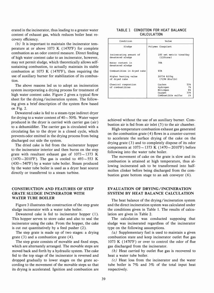
The above reasons led us to adopt an incineration system incorporating a drying process for treatment of high water content cake. Figure 2 gives a typical flow sheet for the drying/incineration system. The following gives a brief description of the system flow based on Fig. 2.
Dewatered cake is fed to a steam-type indirect dryer for drying to a water content of 40 -50%. Water vapor produced in the dryer is carried with carrier gas (air) to a dehumidifier. The carrier gas is circulated with a circulating fan to the dryer in a closed cycle, which prevents odor emitted in the drying process from being discharged out side the system.
The dried cake is fed from the incinerator hopper to the incinerator interior and then bums on the step grate with resultant exhaust gas of 1073-1373 K
(1470-201O°F). The gas is cooled to 493-553 K
(430-540°F) by a water tube boiler. Steam produced by the water tube boiler is used as a dryer heat source directly or transferred to a steam turbine.
CONSTRUCfION AND FEATURES OF STEP
GRATE SLUDGE INCINERATOR WITH
WATER TUBE BOILER
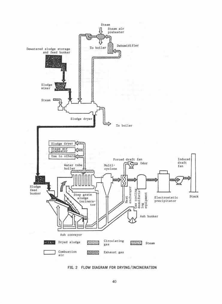
Figure 3 illustrates the construction of the step grate sludge incinerator with a water tube boiler.
Dewatered cake is fed to incinerator hopper (1). This hopper serves to store cake and also to seal the incinerator using the cake. From the hopper, the cake is cut out quantitatively by a feed pusher (2).
The step grate is made up of two stages: a drying grate (3) and a combustion grate (4).
The step grate consists of movable and fixed steps, which are alternately arranged. The movable steps are moved back and forth by a hydraulic system. The cake fed to the top stage of the incinerator is reversed and dropped gradually to lower stages on the grate according to the movement of the movable steps so that its drying is accelerated. Ignition and combustion are
39
TABLE 1 CONDITION FOR HEAT BALANCE
CALCULATION
Condition Value
Sludge Polymer CoagUlant
Incinerating amount of 100 wet metric tons/day dewatered sludge (HOtons)
Water content in 78\ dewatered sludge
Combustibles in dryed cake 65\
Higher heating value 16734 �J/kg of d ryed cake (7194 Btu/1b)
Chemical canpostion Carbon 53\ of canbustibles Hydrogen 7\
Nitrogen 6\ Oxygen 33\ Canbustible sulfur H
achieved without the use of an auxiliary burner. Combustion air is fed from air inlet (5) to the air chamber.
High-temperature combustion exhaust gas generated on the combustion grate ( 4 ) flows in a counter-current to accelerate the surface drying of the cake on the drying grate (3) and to completely dispose of its odor components at 1073 -1373 K (1470-20 10°F) before following into the water tube boiler.
The movement of cake on the grate is slow and its combustion is attained at high temperature, thus allowing incinerated ash to be transformed into halfmolten clinker before being discharged from the combustion grate bottom stage to an ash conveyer (6).
EVALUATION OF DRYING/INCINERATION
SYSTEM BY HEAT BALANCE CALCULATION
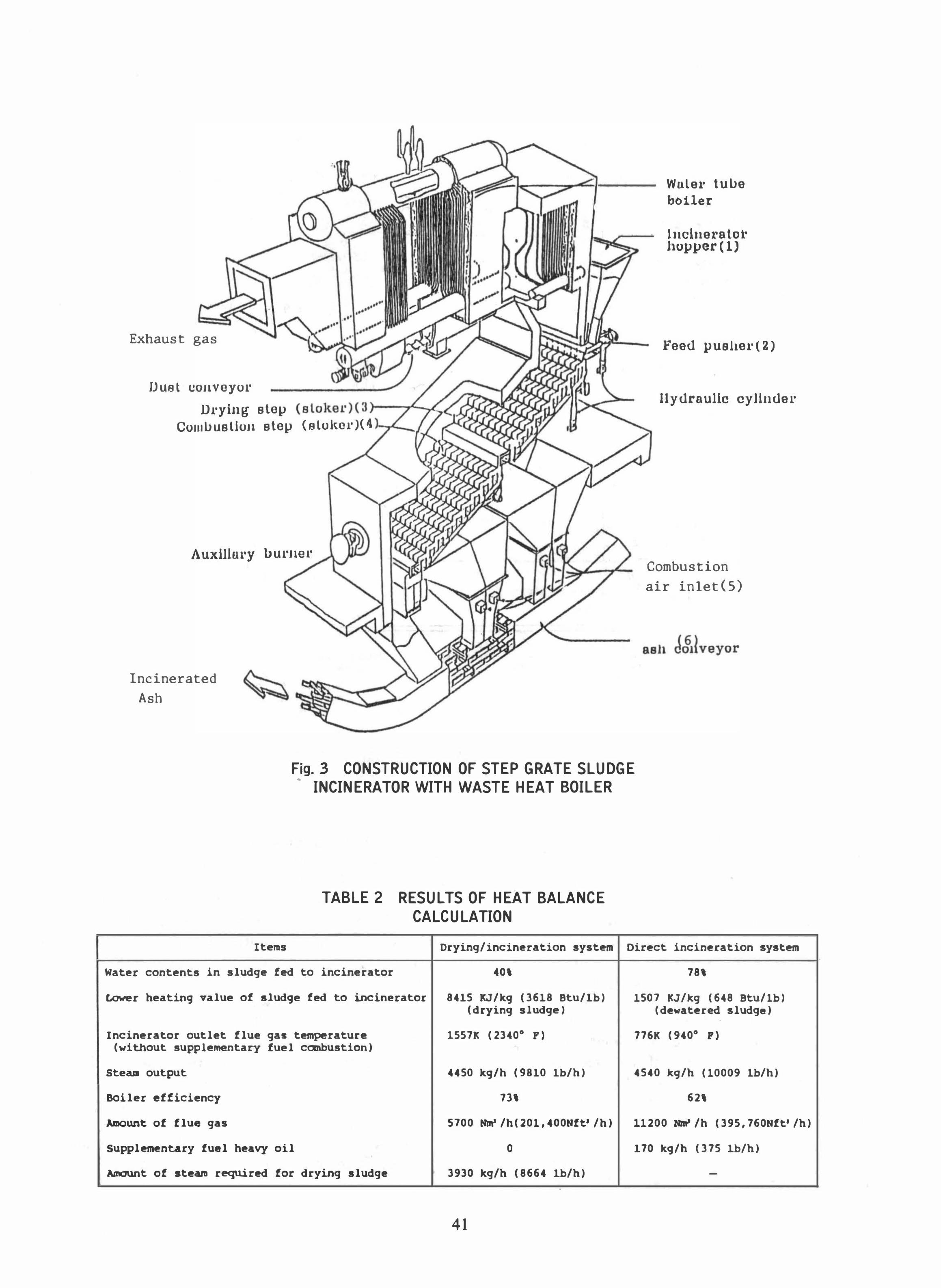
The heat balance of the drying/incineration system and the direct incineration system was calculated under the conditions given in Table 1. The results of calculation are given in Table 2.
The calculation was conducted supposing that sludge was incinerated regardless of the incinerator type on the following assumptions.
(a) Supplementary fuel is used to maintain a given combustion state and keep incinerator outlet flue gas 1073 K (1470°F) or over to control the odor of flue gas discharged from the incinerator.
(b) Heat carried by outlet flue gas is recovered to heat a water tube boiler.
(c) Heat loss from the incinerator and the water tube boiler is 7% and 3% of the total input heat respectively.
Dewatered sludge storage and feed bunker
Sludge mixer
Steam
..
CJ
Sludge dryer
Ash conveyor
Dryed sludge
Combustion air
Steam
To boiler
Circulating gas
Exhaust gas
Induced draft fan
Electrostatic precipitator
Ash bunker
G,\;;ib.�·\�l Steam
FIG.2 FLOW DIAGRAM FOR DRYING/INCINERATION
40
Exhaust gas
Duet COJlveyor
Dl'ying step (slokel')(3 )--r--.L. CUlIIlJuslloJl step (slo!tol')( 1\ 1-,.1._./..1
A uxillul'Y lJ urllel' ""l-...I
Incinerated
Ash
Wulel' tulJe boiler
Incine1'8 tol' hupper(l)
Feed pushel' (2)
lIydrnulic cylinder
Combustion
air inlet(S)
Fig.3 CONSTRUCTION OF STEP GRATE SLUDGE
• INCINERATOR WITH WASTE HEAT BOILER
TABLE 2 RESULTS OF HEAT BALANCE
CALCULATION
Items Drying/incineration system
Water contents in sludge fed to incinerator 40\
Lower heating value of sludge fed to incinerator 8415 KJ/kg (3618 Btu/1b) (drying sludge)
Incinerator outlet flue gas temperature 1557K (2340· F) (without supplementary fuel combustion)
SteaJII output 4450 kg/h (9810 Ib/h)
BOiler efficiency 73\
Amount of flue gas 5700 IIln' /h( 201, 400Hft' /h)
Supplementary fuel heavy oil 0
Amount of steam required for drying sludge 3930 kg/h (8664 Ib/h) .
41
Direct incineration system
78\
1507 KJ/kg (648 Btu/lb) (dewatered sludge)
776K (940· p)
4540 kg/h (10009 Ib/h)
62\
11200 11m' /h (395,760Hft' /h)
170 kg/h (375 Ib/h)
-
Iotal heat quantity
Inc1nerator and b011er heat 10 ..
9.3% 14.17 x 10' IU/h (6.09x1l1' Btu/h)' Heat carr1ed
away by flue gas 12.5%
Heat carried by cake
0.8%
Cake supply 79.8%
Combustion air
0.7%
Steam generat10n 76.3%
Used for dryer ateam
FIG.4 THE HEAT BALANCE DIAGRAMS OF THE
DRYING I INCIN ERA lION SYSTEM
Supplementary fue 1 heavy 011 42.5 % Iota 1 heat quant1ty
Inc1nerator and bo11er heat loss
18.18 x 10' IU/h (7.82x10' Btu/h) 6.9%
Heat carr1ed away by flue gas
22.3%
Heat carried by cake
0.8\
Steam generat10n
69.0%
Air preheater
Suppl1ed to equ1pment requ1re1ng steam 1n plant
FIG.5 THE HEAT BALANCE DIAGRAMS OF THE
DIRECT INCINERATION SYSTEM
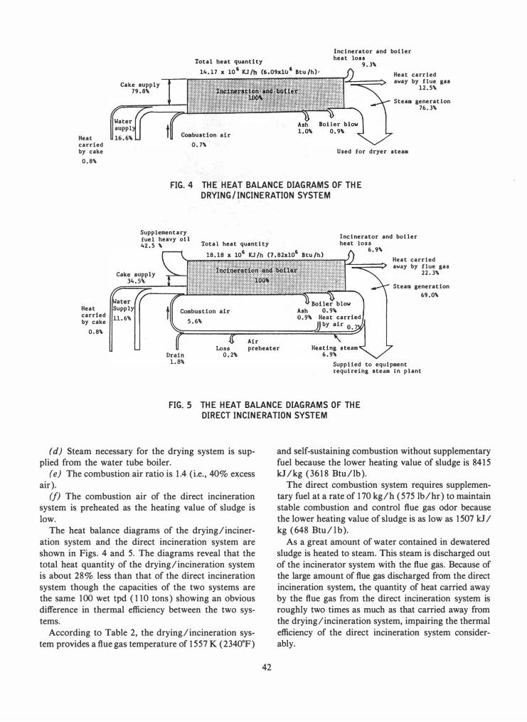
(d) Steam necessary for the drying system is supplied from the water tube boiler.
(e) The combustion air ratio is 1.4 (i.e., 40% excess air).
(/) The combustion air of the direct incineration system is preheated as the heating value of sludge is low.
The heat balance diagrams of the drying/incineration system and the direct incineration system are shown in Figs. 4 and 5. The diagrams reveal that the total heat quantity of the drying/incineration system is about 28% less than that of the direct incineration system though the capacities of the two systems are the same 100 wet tpd (110 tons) showing an obvious difference in thermal efficiency between the two systems.
According to Table 2, the drying/incineration system provides a flue gas temperature of 1557 K (2340°F)
42
and self-sustaining combustion without supplementary fuel because the lower heating value of sludge is 8415 kJ/kg (3618 Btu/lb).
The direct combustion system requires supplementary fuel at a rate of 170 kg/h (575Ib/hr) to maintain stable combustion and control flue gas odor because the lower heating value of sludge is as low as 1507 kJ / kg (648 Btu/l b).
As a great amount of water contained in dewatered sludge is heated to steam. This steam is discharged out of the incinerator system with the flue gas. Because of the large amount of flue gas discharged from the direct incineration system, the quantity of heat carried away by the flue gas from the direct incineration system is roughly two times as much as that carried away from the dryinglincineration system, impairing the thermal efficiency of the direct incineration system considerably.
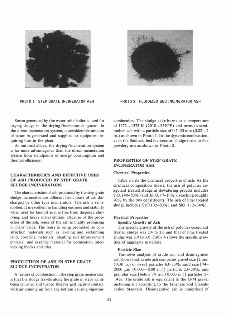
PHOTO 1 STEP GRATE INCINERATOR ASH
Steam generated by the water tube boiler is used for drying sludge in the drying/incineration system. In the direct incineration system, a considerable amount of steam is generated and supplied to equipment requiring heat in the plant.
As outlined above, the drying/incineration system is far more advantageous than the direct incineration system from standpoints of energy consumption and thermal efficiency.
CHARACfERISTICS AND EFFECfIVE USES
OF ASH PRODUCED BY STEP GRATE
SLUDGE INCINERATORS
The characteristics of ash produced by the step grate sludge incinerator are different from those of ash discharged by other type incinerators. The ash is semimolten. It is excellent in handling easiness and stability when used for landfill as it is free from disposal, slurrying, and heavy metal elution. Because of the properties of the ash, reuse of the ash is highly promising in many fields. The reuse is being promoted as construction materials such as leveling and reclaiming land, covering materials, planting soil improvement material, and ceramic material for permeation interlocking blocks and tiles.
PRODUCfION OF ASH IN STEP GRATE
SLUDGE INCINERATOR
A feature of combustion in the step grate incinerator is that the sludge travels along the grate in steps while being churned and turned thereby getting into contact with air coming up from the bottom causing vigorous
43
PHOTO 2 FLUIDIZED BED INCINERATOR ASH
combustion. The sludge cake burns at a temperature of 1373-1573 K (2010-2370°F) and turns to semimolten ash with a particle size of 0.5-50 mm (0.02-2 in.) as shown in Photo 1. In the dynamic combustion, as in the fluidized bed incinerator, sludge turns to fine powdery ash as shown in Photo 2.
PROPERTIES OF STEP GRATE
INCINERATOR ASH
Chemical Properties
Table 3 lists the chemical properties of ash. As the chemical composition shows, the ash of polymer coagulant treated sludge at dewatering process includes Si02 ( 40-50% ) and Al203 (7-19% ), reaching roughly 70% by the two constituents. The ash of lime treated sludge includes CaO (32-60%) and Si02 (12-34%).
Physical Properties
Specific Gravity of Ash
The specific gravity of the ash of polymer coagulant treated sludge was 2.4 to 2.6 and that of lime treated sludge was 2.9 to 3.0. Table 4 shows the specific gravities of aggregate materials.
Particle Size
The sieve analysis of crude ash and disintegrated ash shows that: crude ash comprises gravel size [2 mm (0.08 in.) or over] particles 63-73%, sand size [74-2000 ILm (0.003-0.08 in.)] particles 23-30%, and granular size [below 74 ILm (0.003 in.)] particles 5-14%. The crude ash is equivalent to the G-M gravel including silt according to the Japanese Soil Classification Standard. Disintegrated ash is comprised of
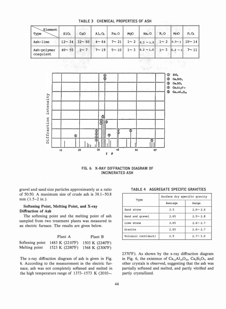
TABLE 3 CHEMICAL PROPERTIES OF ASH
� SiC. CaO AI. 0, Fe. 0
Ash-lime 12-34 32- 60 4-64 7-21
Ash-polymer 40-55 2-7 7-19 5-10 coagulant
�
� (2) 0> 0>
(2) -0>
<5> 0> <3> <3> <D_
�rl J I <3> II1I J
10 20 30 40 2 .8
MgO
1-2
1-3
<3>
I I 50
Na.O K.O MnO P.c.
0.3 -1.0 1-2 0.5-1 10-14
0.2 -1.0 1-3 0.2 -1 7-11
ar 510, (2) 0.,510,
f- 0> 0.,50,
III 6P
<D 0l,S1207 <3> OIIlAI .. O ..
FIG.-6 X-RAY DIFFRACTION DIAGRAM OF
INCINERATED ASH
gravel and sand size particles approximately at a ratio of 50:50. A maximum size of crude ash is 38.1-50.8 mm (1.5-2 in.).
Softening Point, Melting Point, and X-ray
Diffraction of Ash
The softening point and the melting point of ash sampled from two treatment plants was measured in an electric furnace. The results are given below.
Softening point Melting point
Plant A
1483 K (221O°F) 1523 K (2280°F)
Plant B
1503 K (2240°F) 1568 K (2300°F)
The x-ray diffraction diagram of ash is given in Fig. 6. According to the measurement in the electric furnace, ash was not completely softened and melted in the high temperature range of 1373-1573 K (2010-
44
TABLE 4 AGGREGATE SPECIFIC GRAVITIES
Surface dry specific gravity Type
Average Range
Sand stone 2.5 2.0- 2.6
Sand and gravel 2.65 2.5- 2.8
Lime stone 2.65 2.6- 2.7
Granite 2.65 2.6- 2.7
Volcanic rock(dark) 2.9 2.7- 3.0
2370°F). As shown by the x-ray diffraction diagram in Fig. 6, the existence of Ca12Ai140)), Ca)Si207, and other crystals is observed, suggesting that the ash was partially softened and melted, and partly vitrified and partly crystallized.
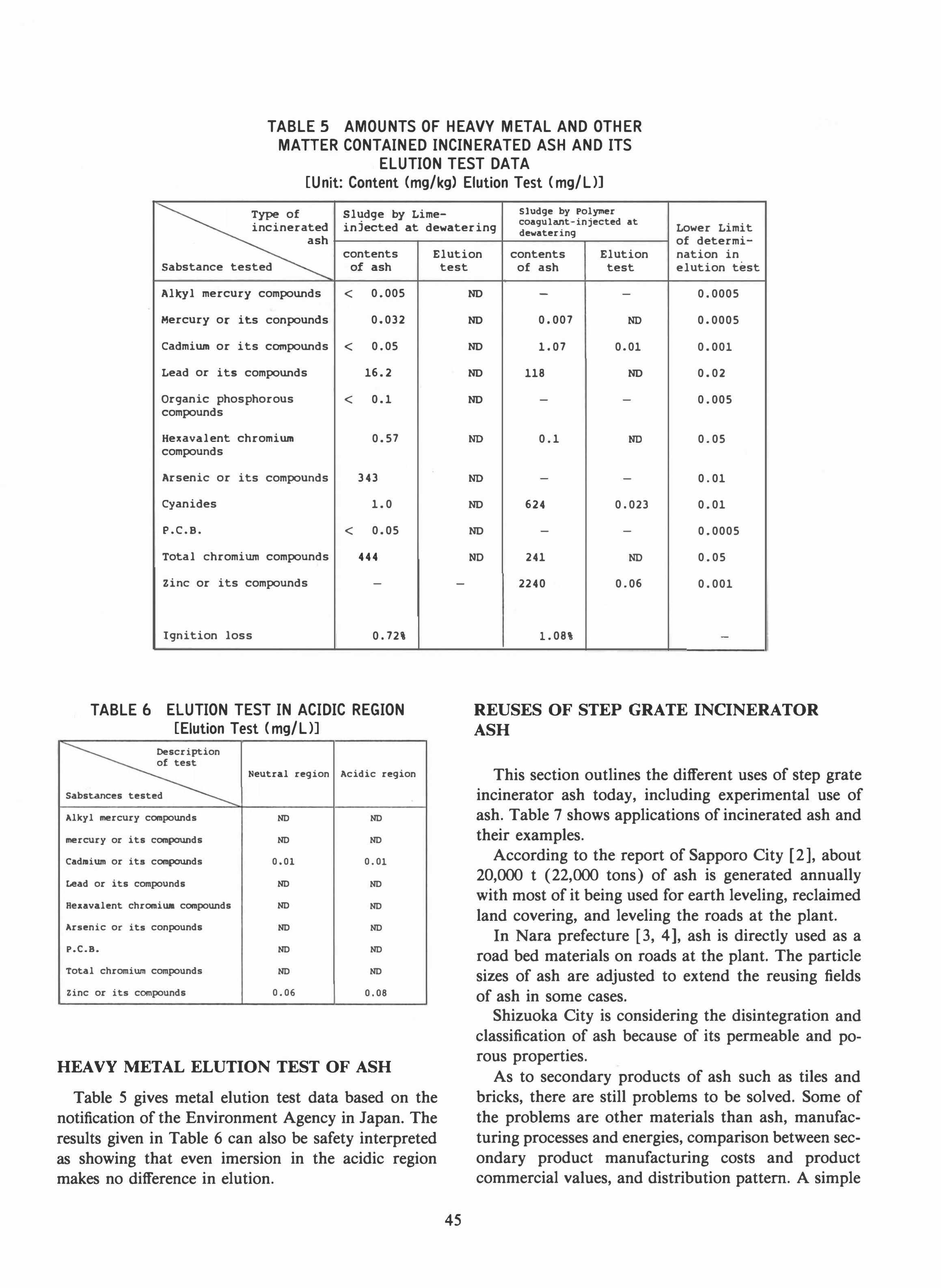
TABLE 5 AMOUNTS OF HEAVY METAL AND OTHER
MAnER CONTAINED INCINERATED ASH AND ITS
ELUTION TEST DATA
[Unit: Content (mg/kg) Elution Test (mg/UJ
Type of Sludge by Lime- Sludge by Polymer coaqulant-injected at
incinerated injected at dewatering Lower Limit dewatering ash of determi-
contents Elution contents Elution nation in Sabstance tested of ash
Al�l mercury compounds < 0.005
Mercury or its conpounds 0.032
Cadmium or its compounds < 0.05
Lead or its compounds 16.2
Organic phosphorous < 0.1 compounds
Hexavalent chromium 0.57 compounds
Arsenic or its compounds 343
Cyanides 1.0
P.C.B. < 0.05
Total chromium compounds 444
Zinc or its compounds -
Ignition loss 0.72\
TABLE 6 ELUTION TEST IN ACIDIC REGION
[Elution Test (mg/UJ Description of test
Neutral regl.on Acidic region
Sabstances tested
Alkyl mercury compounds ND ND
mercury or its compounds ND ND
Cadllium or its compounds 0.01 0.01
Lead or its compounds ND ND
Hexavalent chromium compounds ND ND
Arsenic or its conpounds ND ND
p.e.B. ND ND
Total chromium compounds ND ND
Zinc or its compounds 0.06 0.08
HEAVY METAL ELUTION TEST OF ASH
Table 5 gives metal elution test data based on the notification of the Environment Agency in Japan. The results given in Table 6 can also be safety interpreted as showing that even imersion in the acidic region makes no difference in elution.
test
-
45
of ash test elution test
ND - - 0.0005
ND 0.007 ND 0.0005
ND 1.07 0.01 0.001
ND 118 ND 0.02
ND - - 0.005
ND 0.1 NO 0.05
ND - - 0.01
ND 624 0.023 0.01
ND - - 0.0005
NO 241 ND 0.05
2240 0.06 0.001
1.08' -
REUSES OF STEP GRATE INCINERATOR
ASH
This section outlines the different uses of step grate incinerator ash today, including experimental use of ash. Table 7 shows applications of incinerated ash and their examples.
According to the report of Sapporo City [2], about 20,000 t (22,000 tons) of ash is generated annually with most of it being used for earth leveling, reclaimed land covering, and leveling the roads at the plant.
In Nara prefecture [3, 4], ash is directly used as a road bed materials on roads at the plant. The particle sizes of ash are adjusted to extend the reusing fields of ash in some cases.
Shizuoka City is considering the disintegration and classification of ash because of its permeable and porous properties.
As to secondary products of ash such as tiles and bricks, there are still problems to be solved. Some of the problems are other materials than ash, manufacturing processes and energies, comparison between secondary product manufacturing costs and product commercial values, and distribution pattern. A simple
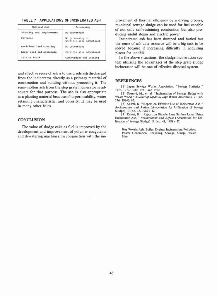
TABLE 7 APPLICATIONS OF INCINERATED ASH
Applications Processing
Planting soil improvement No processing
Pavement No processing or particle size adjustment
Reclaimed land covering No processing
Lower road bed aggregate Particle size adjustment
Tile or brick Compounding and burning
and effective reuse of ash is to use crude ash discharged from the incinerator directly as a primary material of construction and building without processing it. The semi-molton ash from the step grate incinerator is adequate for that purpose. The ash is also appropriate as a planting material because of its permeability, water retaining characteristic, and porosity. It may be used in many other fields.
CONCLUSION
The value of sludge cake as fuel is improved by the development and improvement of polymer coagulants and dewatering machines. In conjunction with the im-
46
provement of thermal efficiency by a drying process, municipal sewage sludge can be used for fuel capable of not only self-sustaining combustion but also producing useful steam and electric power.
Incinerated ash has been dumped and buried but the reuse of ash as a resource will be a big task to be solved because if increasing difficulty in acquiring places for landfill.
In the above situations, the sludge incineration system utilizing the advantages of the step grate sludge incinerator will be one of effective disposal system.
REFERENCES
[1] Japan Sewage Works Association. "Sewage Statistics." 1978, 1979, 1980, 1981, and 1982.
[2] Uozumi, M., et. aI. "Incineration of Sewage Sludge with Waste Wood." Journal of Japan Sewage Works Association. 21 (no. 236, 1984): 85.
[3] Kawai, K ... Report on Effective Use of Incinerator Ash. " Reclaimation and Refuse (Association for Utilization of Sewage Sludge) 10 (no. 37, 1987): 42.
[4] Kawai, K. "Report on Bicycle Lane Surface Layer Using Incinerator Ash." Reclaimation and Refuse (Association for Utilization of Sewage Sludge) 11 (no. 41, 1988): 32.
Key Words: Ash; Boiler; Drying; Incineration; Pollution; Power Generation; Recycling; Sewage; Sludge; Waste Heat