Embed Size (px)
Citation preview

This article was downloaded by: [University of Illinois at Urbana-Champaign]On: 29 November 2011, At: 11:46Publisher: Taylor & FrancisInforma Ltd Registered in England and Wales Registered Number: 1072954 Registeredoffice: Mortimer House, 37-41 Mortimer Street, London W1T 3JH, UK
Engineering OptimizationPublication details, including instructions for authors andsubscription information:http://www.tandfonline.com/loi/geno20
Incorporating security considerationsinto optimal product architecture andcomponent sharing decision in productfamily designAlvaro J. Rojas Arciniegas a & Harrison M. Kim aa Industrial and Enterprise Systems Engineering, University ofIllinois at Urbana-Champaign, 104 S. Mathews Avenue, Urbana, IL,61801, USA
Available online: 05 Jul 2011
To cite this article: Alvaro J. Rojas Arciniegas & Harrison M. Kim (2011): Incorporating securityconsiderations into optimal product architecture and component sharing decision in product familydesign, Engineering Optimization, DOI:10.1080/0305215X.2011.561842
To link to this article: http://dx.doi.org/10.1080/0305215X.2011.561842
PLEASE SCROLL DOWN FOR ARTICLE
Full terms and conditions of use: http://www.tandfonline.com/page/terms-and-conditions
This article may be used for research, teaching, and private study purposes. Anysubstantial or systematic reproduction, redistribution, reselling, loan, sub-licensing,systematic supply, or distribution in any form to anyone is expressly forbidden.
The publisher does not give any warranty express or implied or make any representationthat the contents will be complete or accurate or up to date. The accuracy of anyinstructions, formulae, and drug doses should be independently verified with primarysources. The publisher shall not be liable for any loss, actions, claims, proceedings,demand, or costs or damages whatsoever or howsoever caused arising directly orindirectly in connection with or arising out of the use of this material.
Engineering OptimizationiFirst, 2011, 1–20
Incorporating security considerations into optimal productarchitecture and component sharing decision in product
family design†
Alvaro J. Rojas Arciniegas and Harrison M. Kim*
Industrial and Enterprise Systems Engineering, University of Illinois at Urbana-Champaign,104 S. Mathews Avenue, Urbana, IL 61801, USA
(Received 19 July 2010; final version received 19 January 2011 )
Selecting the appropriate components to share in product family design is not a trivial decision; especiallywhen a firm wants to protect the most sensitive information contained in their products from being exposedto users, third-party manufacturers, or undesirable agents. This article proposes tools to help designersidentify sets of components containing sensitive information, as well as components that are candidatesfor sharing amongst the family. It also finds the most desirable component arrangement in each productthat facilitates sharing while protecting the sensitive information that has been previously identified. Theproposed framework is applied to three printers in which the architecture used for the ink cartridgesand printheads are significantly different. Third-party manufacturers and remanufacturers offer their ownalternatives for these subsystems (ink cartridges and printheads) since the customer for printer suppliesis always looking for a cheaper alternative; meanwhile, the original equipment manufacturers attempt tosecure their products and retain their customers with original supplies. The functional description of thesystem is analysed to identify the sensitive components for each printer; then, the optimal clustering strategyis found, as well as the set of components that are candidates for sharing, according to their connectivityand the security considerations.
Keywords: product family design; product security; information hiding; component sharing; productarchitecture
1. Introduction
Product family design is a field that traditionally encompasses the selection of a common set ofcomponents or subsystems (product platform) that can be used to develop products (variants)easily (Meyer and Lehnerd 1997) in order to fulfil a wider range of market needs. The authorsexplored these decisions in Rojas Arciniegas and Kim (2011), proposing a framework to obtainthe set of components to share across the family, as well as the optimal architecture for eachproduct. The work presented in this article is a logical progression from that framework including
*Corresponding author. Email: [email protected]†An earlier version of this article was presented at the 2010ASME International Design Engineering Technical Conference(Rojas and Kim 2010).
ISSN 0305-215X print/ISSN 1029-0273 online© 2011 Taylor & FrancisDOI: 10.1080/0305215X.2011.561842http://www.informaworld.com
Dow
nloa
ded
by [
Uni
vers
ity o
f Il
linoi
s at
Urb
ana-
Cha
mpa
ign]
at 1
1:46
29
Nov
embe
r 20
11

2 A.J. Rojas Arciniegas and H.M. Kim
a new aspect of securing sensitive components into the decision of establishing the componentsto share and the optimal architecture for multiple products.
The architecture of a product is understood as the allocation of the functions in the physicalcomponents of the product (Ulrich 1995), and it is a key aspect for family design since it affectsall the variants developed from the platform. However, the connectivity between components isnot the only aspect to consider when determining the components to share in a family. In manycases, there exists sensitive information in each product that the manufacturer would not wantto be accessible by the user or third-party manufacturers; then, the security of those sensitivecomponents or interfaces becomes a concern for the designers.
These security concerns are also evident in the military domain where the term ‘Anti-Tamper’is usually used to denote the requirements (or expectations) of a system or subsystem to deter anyefforts to reverse engineer, exploit, or develop countermeasures for critical technology and should,in this manner, add longevity to the system (US-DoD 2010). Nevertheless, the guidelines andrequirements have been developed mostly for software and electronics in which the programmablenature of these areas facilitate techniques such as encryption, code obfuscation, hardware keys,and dynamic reconfiguration (Atallah et al. 2004, Porter et al. 2009). In the physical/mechanicaldomain it is still a challenge to translate these protections even when the ideas and concerns arestill valid.
Some manufacturing techniques allow encapsuling some components in a very secure manner;custom made integrated circuits, in-mold inserts for injection molding, and Micro Electro-Mechanical Systems (MEMS) are just a few examples. Having these capabilities at hand, itbecomes important to identify which component or information is sensitive and what could be thebest way to protect it. This article aims to help designers secure those components or relationshipsthat are sensitive by using modularity to hide information, while considering component sharingand optimal architecture for multiple products.
The remaining sections of the article proceed as follows: a review of the relevant literature on thistopic is presented in Section 2; the sharing decision framework is introduced in Section 3; whichis followed by its application to an illustrative example in Section 4; and the article concludeswith Section 5, which summarizes the proposed framework and the implications of the observedresults for future work.
2. Literature review
In product architectural analysis, a few terms in common use may sometimes have confusingimplications; therefore, in this article a component is taken to mean an element (or group ofelements treated as a single part) that is a constituent piece of a product; a module or clusterrefers to a group of components that ideally are highly interconnected to each other but are onlyweakly related to the rest of the product. A unit is a generic term used to refer to a componentthat may be viewed either as a component or as a module interface, depending on the productarchitecture. An interface refers to a component inside a module being connected to a componentoutside the module. Finally, a product means a collection of modules and components that interactto perform a common task.
A common tool to model the product is the Design Structure Matrix (DSM) as indicated inBrowning (2001). The DSM was introduced by Steward (1981) and it captures the interconnectionsof a product, relating its components in columns and rows of a matrix. Each cell represents arelationship between components, whether it means geometrical joints, electrical connections,material flow, etc. Multiple approaches have used this representation of the product to find theoptimal module definition by clustering the cells with strong relationships among components
Dow
nloa
ded
by [
Uni
vers
ity o
f Il
linoi
s at
Urb
ana-
Cha
mpa
ign]
at 1
1:46
29
Nov
embe
r 20
11
Engineering Optimization 3
(see, for example, Yu et al. 2007, Wang and Antonsson 2004). This topic will be further exploredin Section 2.2.
When considering a family of products, the architectural analysis is crucial since it is necessaryto determine the common structure (platform) for the family. Simpson (2004) highlights that themain objective when creating a platform is to facilitate the generation of new products by havinga common structure from which new variants can be developed. However, trying to capture therelationships, similarities, or differences among multiple products using multiple DSMs is not aneasy task. Each DSM is different in size and content, making it very difficult to relate to otherDSMs. In Rojas Arciniegas and Kim (2011), the authors used the Function-Component Matrix(FCM) from Strawbridge et al. (2002) to relate the components from different products and findthe ones that fulfil identical functions. An FCM is a binary matrix that captures the relationshipbetween the components of a product (columns) and the functions they fulfil (rows).
Different criteria have been used for determining which components to share: cost consider-ations (Browning and Eppinger 2002, Zacharias and Yassine 2007, Moon et al. 2008), Bill ofMaterials (BOM) (Steva et al. 2006), product attributes (Tucker and Kim 2008), environmentalconcerns (Dahmus and Gutowski 2007, Kwak et al. 2007, Pandey and Thurston 2008), productdesign variables (Khajavirad and Michalek 2008, Khajavirad et al. 2009), component interconnec-tions (RojasArciniegas and Kim 2011), etc. The previous approach for defining which componentsto share is explored in Section 2.3. Nevertheless, this decision may expose certain information,components, or interfaces that are sensitive for the manufacturer. Baldwin and Clark (2000) gen-eralized the idea of information hiding used in software engineering, proposing that the moduledefinition is a form of abstraction in which the information that is encapsulated or contained in themodule becomes hidden for the rest of the system. The only visible information from a moduleis the one defined by the interfaces, the connections with other components outside the module.
2.1. Security and information hiding
The security of a product is a concept difficult to quantify. Harston and Mattson (2009) introduceda set of metrics defining a ‘barrier’ (the difficulty of extracting information from the product)and the ‘time to reverse engineer’ a product, based on Ohm’s law and the model of an RCcircuit. Ideally, making a product secure may mean maximizing the barrier to extracting sensitiveinformation; however, the estimation of these parameters depends on the skills and resourcesavailable to the person performing the information extraction, making them very specific andsomewhat subjective.
Similarly, the term ‘anti-tamper’ technology has been used in the military context to denotetechnologies that prevent unauthorized access to specific information (see Keller 2009).An attemptto design anti-tamper circuits is discussed in Porter et al. (2009), in which programmable circuitsare dynamically reconfigured to prevent unwanted reconstruction of the functionality of the circuitby reverse engineering techniques. A more general idea is described below.
The term ‘information hiding’ was introduced by Parnas (1972) in the context of softwareengineering, and has been used as the guideline to define the modules of a program. The idea isto decompose a system into modules in order to hide information that is likely to change, or theinformation that is not supposed to be accessed by the rest of the program.
By isolating or encapsulating certain information, the developer is restricting access to thatinformation to whatever can be inferred by the interfaces (information exchanged to the rest ofthe system) as discussed by Hughes and Shmatikov (2004); therefore, the security of a system canbe improved if the module boundaries are carefully defined to isolate the sensitive information.The concept is very general and can be used in other contexts (as suggested in Baldwin and Clark2000), including product development, as a way to handle the complexity of a design.
Dow
nloa
ded
by [
Uni
vers
ity o
f Il
linoi
s at
Urb
ana-
Cha
mpa
ign]
at 1
1:46
29
Nov
embe
r 20
11
4 A.J. Rojas Arciniegas and H.M. Kim
Usually, the information/component/interface that is sensitive in a product is easy to identifyfor the designer; however, trying to protect it from the user or third-party manufacturer is not soeasy. Very often, the core elements of a product are highly interconnected to the rest of the system,making it difficult to enclose completely in a module. Then it becomes crucial clearly to identifyand separate the internal (hidden) resources of a module from thse that can be accessed by therest of the system or users (O’Hearn et al. 2009).
A simple case is discussed in Legrand (2007), in which the tradeoff between modularity andsecurity is explored for ‘protected distribution systems’. These systems are used for the protectionof networks and are custom made, where applying a modular design for the conduit leads to theexposure of the network at the module boundaries, thus compromising the security of the entiresystem. Then, the challenge for the product designers is to find an optimal component arrangementthat preserves the desired protection for those sensitive elements.
2.2. Optimal clustering for product architecture
In Wang and Antonsson (2004) and Yu et al. (2007), the optimal architecture for a product isachieved through the use of the Minimum Description Length (MDL) principle. This principlepromotes the simplest description for any structure; thence, each component arrangement of aproduct can be coded by a model in which the simpler the model is, the shorter the descriptionis. In the end, the idea is to measure the length of the description and find the minimum, whichcorresponds to the simplest (optimal) component arrangement for the product.
Both approaches use this same principle, but in different manners. Yu et al. (2007) used adescription of the overall structure and accounted for two types of mismatch between a modeland the actual product: type I corresponds to the relationships between components that are leftoutside the modules defined by the model; type II corresponds to the relationships inside themodules that are weak or do not exist (recall that components inside the modules should bestrongly interconnected). The formulation is as follows:
fMDL = (1 − α − β)
(ncl log2 nc + log2 nc
ncl∑i=1
cli
)
+ α[S1(2 log2 nc + 1)] + β[S2(2 log2 nc + 1)]. (1)
In this formulation, the first term corresponds to the length of the overall model, while the secondand third terms correspond to the mismatch lengths of types I and II, respectively. ncl is the numberof clusters, nc is the total number of components of the product, cli is the number of elements incluster i, and α and β are weighting factors for the mismatches. The terms S1 and S2 account forthe mismatches and are defined as follows:
S1 =∑d ′
ij =1
(1 − pij ); S2 =∑d ′
ij =0
(pij );
pij = dij − dmin
dmax − dmin; dmax = maxij dij ; dmin = minij dij ;
(2)
where dij is the entry of the ith row and the j th column of the DSM, and pij is the same entrynormalized. The entry of the ideal binary DSM described by the model is d ′
ij , in which there areno mismatches, i.e. all the entries are ‘1’ inside the clusters and ‘0’ outside the clusters.
Dow
nloa
ded
by [
Uni
vers
ity o
f Il
linoi
s at
Urb
ana-
Cha
mpa
ign]
at 1
1:46
29
Nov
embe
r 20
11

Engineering Optimization 5
On the other hand, Wang and Antonsson (2004) used a formulation based on the number oflinks from each component. This formulation allows a representation of each component (unit)in the product as follows:
MDL(u)j = − log2
⎛⎝N
(u)j /
N(u)∑k=1
Nk
⎞⎠ (3)
in which N(u)j is the number of units connected to unit j , and N(u) is the number of units at the
level in which the unit j is. In this context, two units are considered to be at the same level if theyare inside the same module or outside every module. Since a unit can be seen as a component ifit is considered inside a module, but also as an interface if it has connections outside the module,the total representation of unit j in product k would be
MDLkj = MDL(c)
j + MDL(o)j = −
∑u={c,o}
log2
⎛⎝N
(u)j /
N(u)∑k=1
Nk
⎞⎠, (4)
where ‘c’represents components and ‘o’interfaces. This abstraction of the representation becomesvery useful when analysing how tightly connected each element of the product is.
2.3. Optimal sharing decision making
Many criteria have been used to define the set of components to share; however, when consideringproduct architecture, in Rojas Arciniegas and Kim (2011), the authors used the Impact Metric(IM) and the FCM to establish the suitable candidates for sharing. The IM introduced by Rojas andEsterman (2008), gives a proxy for the easiness to change a component under a given architecture.The formulation is as follows:
IMkj = MDLk
j CIkj , (5)
in which the CIkj corresponds to the Coupling Index (CI) of component j in product k. The CIwas introduced by Martin and Ishii (2002) and the formulation is based in the DSM that containsthe sensitivity analysis for the impact of a change in the specifications of the components. Thisassumes that the components in the columns supply the specification and the components in therows receive the specifications. Each row and column of the DSM is added giving the CI-Receiving(CIR) for the rows, and the CI-Supplying (CIS) for the columns. The total CI for each componentsis the sum of the CIS and the CIR as follows:
CIkj = CISkj + CIRk
j =nk
c∑i=1
DSMk(i, j) +nk
c∑i=1
DSMk(j, i). (6)
The IM for each component of each product is an indication of how easy it is to change a particularcomponent. Nevertheless, in order to identify common components across different products, itis necessary to find common ground. Therefore, the authors used the FCM to match componentsfrom different products by the functions they fulfil. The criterion was to find the set of componentsthat fulfil the same functions in a pair of products, and analyse if the sum of IM scores from thecomponents involved was below a threshold set by the designer. In this manner, the pairwise eval-uation was conducted for all the products in the family. In the end, the set of components to sharefrom all the products was established and stored in a binary decision vector (Y k) for each product k.
In RojasArciniegas and Kim (2011), after the decision vectors were established, an optimizationproblem was solved for each product of the family with a dual objective: on one hand, finding
Dow
nloa
ded
by [
Uni
vers
ity o
f Il
linoi
s at
Urb
ana-
Cha
mpa
ign]
at 1
1:46
29
Nov
embe
r 20
11

6 A.J. Rojas Arciniegas and H.M. Kim
an optimal clustering of the components, making use of the product MDL representation ofEquation (1); meanwhile, the decision vector was multiplied by the IM vector from Equation (5)selecting the components to include in the objective function, allowing those components to bechanged easily in the product. The optimization problem was solved using genetic algorithmsand the chromosome was a binary string that represented a particular component arrangement inclusters for product k, also represented in a binary matrix form (Xk). In this matrix, the columns arethe components and the rows are the clusters; therefore, each cell (i, j) indicates if the componentj belong to the cluster i. The objective function was defined as follows:
f (Xk) = f kMDL + (Y k)TIMk. (7)
Since the IM depends on the current architecture of the product, the process was iterative. Ateach iteration (t) a new component arrangement was achieved for each product, progressivelyestablishing the final list of components to share. The process was repeated until the change inthe decision vectors for all the products being considered was below a given tolerance ε:
m∑k=1
‖Y k(t) − Y k(t − 1)‖2
nkc
≤ ε. (8)
3. Generating security constraints for optimal product family design
The framework presented in this section builds upon the work presented in Rojas Arciniegasand Kim (2011) (also described in Section 2.3). It incorporates security considerations whenselecting the optimal candidates for sharing across multiple products, simultaneously identifyingthe optimal component arrangement for each individual product.
3.1. Defining sensitive components
Rojas Arciniegas and Kim (2011) proposed the use of the functional mapping captured in theFCMs to automatically identify the components that could be matched between products basedon the functions they perform. Since the FCM for each product is already available (or at least itis a requirement for the application of the framework), this information can be used to designatethe sets of sensitive components, by relating the functions that are ‘critical’ to the componentsthat perform those in each product. Thus, components can be grouped in sets based on the samefunctional mapping.
The main difference with the approach presented in Rojas and Kim (2010) is that the sets ofsensitive components are automatically generated using the FCM and designating the ‘critical’functions, which are independent of the realization of each product. The term critical is usedto denote the functions that carry most of the intellectual property of the product and thereforeshould be protected. These functions are easier to identify than individual components in eachproduct, since those are the functions in which companies usually invest more resources and haveheavy research and development.
The critical functions are designated by means of a binary vector (CrFun) for which a one(1) would indicate that the function is critical. The size of the vector is equal to the number offunctions (nf ) considered for the analysis (also the number of rows in the FCMs). CrFun is theinput required from the designer and corresponds to the nature of the company and where theintellectual property is.
Dow
nloa
ded
by [
Uni
vers
ity o
f Il
linoi
s at
Urb
ana-
Cha
mpa
ign]
at 1
1:46
29
Nov
embe
r 20
11

Engineering Optimization 7
The automated detection of the sensitive components and its clustering in restricted sets isperformed (similarly to the functional matching proposed in Rojas Arciniegas and Kim 2011) byexamining the vector CrFun for critical functions in the following manner.
• A vector keeps track of the critical functions evaluated throughout the selection of the restrictedsets, denoted as the master function-vector (f-v).
• Another vector marks the critical functions related to the matching components, denoted as thelocal f-v, to form each restricted set.
• A different vector is used to register the components related to the critical functions in the localf-v forming each restricted set. This vector is denoted as the component-vector (c-v).
• A matrix is formed row by row with the results from the c-v and it is returned at the end of theidentification process, in which the rows indicate the restricted sets (nrcl) of components forproduct k. This matrix is denoted as the security matrix (SecMk).
The master f-v and the local f-v are binary vectors with nf elements, while the c-v is a vector withnc elements. The security matrix (SecMk), is a binary matrix of dimensions nrcl by nc. An exampleof a SecM for a product with eight components is shown in Table 1, in which components B, Cand D are required to be inside a module. Similarly, components F, G and H are also required tobe in a module. The requirement does not imply that the modules should be different from oneanother – it could be one module that contains both sets, but the sets have to be fully contained inthe module.
The selection of restricted sets of components is conducted as follows.
Step 1. Initialize the master f-v with a zero vector and start by evaluating the first function(i = 1).
Step 2. Check if the function is critical; if yes, continue; if not, go to Step 14.Step 3. Check if the function has been evaluated before (master f-v(i)=1?); if yes, go to Step
14; if not, continue.Step 4. Mark the master f-v with a ‘1’ for the corresponding function, and initialize the local f-v
and c-v with zero vectors.Step 5. Mark the local f-v with a ‘1’ for the corresponding function, and set t = i.Step 6. Check if the function should be considered (local f-v(t)=1?); if yes, continue; if not, go
to Step 11.Step 7. Find components related to the function following the row of the FCM corresponding
to the function being evaluated until a ‘1’ is found.Step 8. Mark the corresponding component in the c-v.Step 9. Find other critical functions related to the component following the column of the
corresponding component and mark them in the local f-v.Step 10. Return to Step 7 until all the components have been evaluated.Step 11. Continue to the next function (t = t + 1) and return to Step 6 until all the functions in
the local f-v have been evaluated.Step 12. Mark the functions marked in the local f-v into the master f-v.Step 13. Check if the c-v is empty; if not, create a new row for SecMk and mark the components
in the c-v into the row of the matrix.
Table 1. Example of the security matrix (SecM) for a product of eight components.
Components
A B C D E F G H
Set1 0 1 1 1 0 0 0 0Set2 0 0 0 0 0 1 1 1
Dow
nloa
ded
by [
Uni
vers
ity o
f Il
linoi
s at
Urb
ana-
Cha
mpa
ign]
at 1
1:46
29
Nov
embe
r 20
11

8 A.J. Rojas Arciniegas and H.M. Kim
Step 14. Continue the evaluation of the next function (i = i + 1) and return to Step 2 until allthe functions have been evaluated.
In order to achieve this restriction, a new term is added in the MDL formulation. This termaccounts for the mismatch of the current architecture to the constraint designated in the SecM forthe product. The formulation in Equation (1) is redefined as follows:
fMDL = (1 − α − β − γ )
(ncl log2 nc + log2 nc
ncl∑i=1
cli
)
+ α[S1(2 log2 nc + 1)] + β[S2(2 log2 nc + 1)]+ γ [S3(log2 nc + log2 nrcl + log2 ncl)], (9)
in which γ is a weighting factor, nrcl is the number of restricted sets of components (rows of SecM),and S3 accounts for the mismatches with the restricted sets. The description of this mismatch wouldbe given by the component number, the restricted set number, and the cluster number; therefore,the description length is given by (log2 nc + log2 nrcl + log2 ncl). S3 counts the number of thesemismatches in the following manner:
S3 =nrcl∑i=1
ncl∑j=1
[SecMi·(e − Xj ·)T min
{min
{SecMi·XT
j ·, SecMi·(e − Xj ·)T}, 1
}]
+nrcl∑i=1
⎡⎣SecMi·eT
⎛⎝1 − min
⎧⎨⎩
ncl∑j=1
SecMi·XTj ·, 1
⎫⎬⎭
⎞⎠
⎤⎦ , (10)
where SecMi· corresponds to the ith row vector of SecM, Xj · the j th row vector of X, and e
is a unity row vector of the appropriate dimension. The first term accounts for the mismatchesbetween each cluster
(Xj ·
)and each restricted set (SecMi·), preventing overcounting mismatches
when no component in the restricted set is in the cluster. The second term penalizes the restrictedsets that are not included in any of the clusters.
This modification to the original MDL formulation finds an optimal clustering for the productwhile maintaining the constraints defined in SecM through the optimization process.
3.2. Component sharing
The component sharing decision is also affected by the restriction on the sensitive components.In Rojas Arciniegas and Kim (2011), a candidate for sharing gets isolated in a cluster by itself tofacilitate the sharing process. Having a sensitive component selected as a candidate would violatethe restriction imposed by SecM, unless it is selected along with all the other components of therestricted set and it would have to be shared as a module. Therefore, it is necessary to redefine thedecision vector Y k , so this aspect is taken into consideration. The reformulation is as follows:
Y kc (j) = Y k(j)
nrcl∏i=1
(1 − SecMk(i, j)
)
Y km(l) = min
{nrcl∑i=1
[(1 − min
{(SecMk(i, ·)e − Xk(l, ·)SecMk(i, ·)′) , 1
})
× (1 − min
{(SecMk(i, ·)e − Y kSecMk(i, ·)′) , 1
})], 1
}
∀i ∈ {1, . . . , nrcl}, j ∈ {1, . . . , nc}, l ∈ {1, . . . , ncl},
⎫⎪⎪⎪⎪⎪⎪⎪⎪⎪⎪⎪⎪⎬⎪⎪⎪⎪⎪⎪⎪⎪⎪⎪⎪⎪⎭
(11)
Dow
nloa
ded
by [
Uni
vers
ity o
f Il
linoi
s at
Urb
ana-
Cha
mpa
ign]
at 1
1:46
29
Nov
embe
r 20
11
Engineering Optimization 9
where Y kc exclude all the restricted components of product k from Y k; Y k
m indicates which mod-ules contain restricted sets entirely and are suitable candidates according to Y k . The originaldecision vector Y k is still obtained by pairwise comparisons between products, establishing afunctional matching of components from different products and evaluating if the sum of the IMscore for the components related is below a given threshold. This analysis determines the compo-nents that are easy to change under the current architecture, making those candidates for sharingacross the family of products. (Refer to Section 3.3 of Rojas Arciniegas and Kim 2011 for moredetails.)
The IM is also computed for the modules defined in Xk by treating each cluster as a component,aggregating the external connections, computing the CI for the cluster, and multiplying it by theMDL of the module. The result of this calculation is stored in the vector IMk
m.The subproblem (clustering optimization for each product k) is redefined as follows:
min f k = α1Ykc IMk + α2Y
kmIMk
m + f kMDL, (12)
where α1 and α2 are weighting factors. This objective function determines the optimal clusteringstrategy for the individual products based on the DSM of the product (fixed), the restrictions forsensitive components defined in the SecM (fixed), the modified decision vector passed from themaster problem (component sharing) as a parameter, and evaluates the chromosome (Xk) duringthe process of optimization until finding the optimal clustering strategy.
3.3. Framework overview
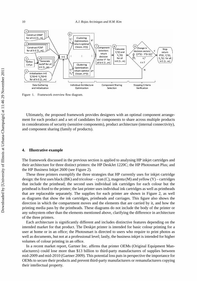
The framework defined in Rojas Arciniegas and Kim (2011) requires adjustments to accommo-date the new criteria involved in the analysis. A new matrix SecM is required for each product,and the objective function in the optimization process requires two important modifications toinclude the security considerations: first, to incorporate a mismatch between the restricted setsin SecM and the clustering strategy X for the MDL model; and second, to alter the decisionvector to exclude the sensitive components that are selected for sharing without all the ele-ments in the corresponding restricted set. Therefore, the overall framework proceeds as follows(Figure 1).
Step 1. Construct the product DSM for each variant of the family.Step 2. Construct the FCM for each product and include all the functions in the family.Step 3. Define the set of critical functions in the binary vector CrFun.Step 4. Generate the restricted sets of components (SecM) for each product.Step 5. Initialize the modified decision vectors Y k
c and Y km with zero vectors.
Step 6. Run the optimization for each product separately. Include both the modified MDL rep-
resentation of the product(f k
MDL
)and the IM of the modified selection of components
and modules for sharing (α1Ykc IMk + α2Y
kmIMk
m), following Equation (12) to obtain anew clustering strategy Xk that considers the security of the sensitive components andcomponent sharing.
Step 7. Run the component sharing selection algorithm to obtain the decision vectors Y for eachproduct in the analysis. This algorithm calculates the IM for all the components andperforms functional matching in order to find candidates for sharing with low IM. Theselection of the candidates depends on a threshold level for the IM.
Step 8. Obtain the modified decision vectors Y kc and Y k
m for each product.Step 9. Verify if a stopping criterion is met (i.e. change in all the decision vectors below tolerance
ε); if not, return to Step 6.
Dow
nloa
ded
by [
Uni
vers
ity o
f Il
linoi
s at
Urb
ana-
Cha
mpa
ign]
at 1
1:46
29
Nov
embe
r 20
11
10 A.J. Rojas Arciniegas and H.M. Kim
Figure 1. Framework overview flow diagram.
Ultimately, the proposed framework provides designers with an optimal component arrange-ment for each product and a set of candidates for components to share across multiple productsin considerations of security (sensitive components), product architecture (internal connectivity),and component sharing (family of products).
4. Illustrative example
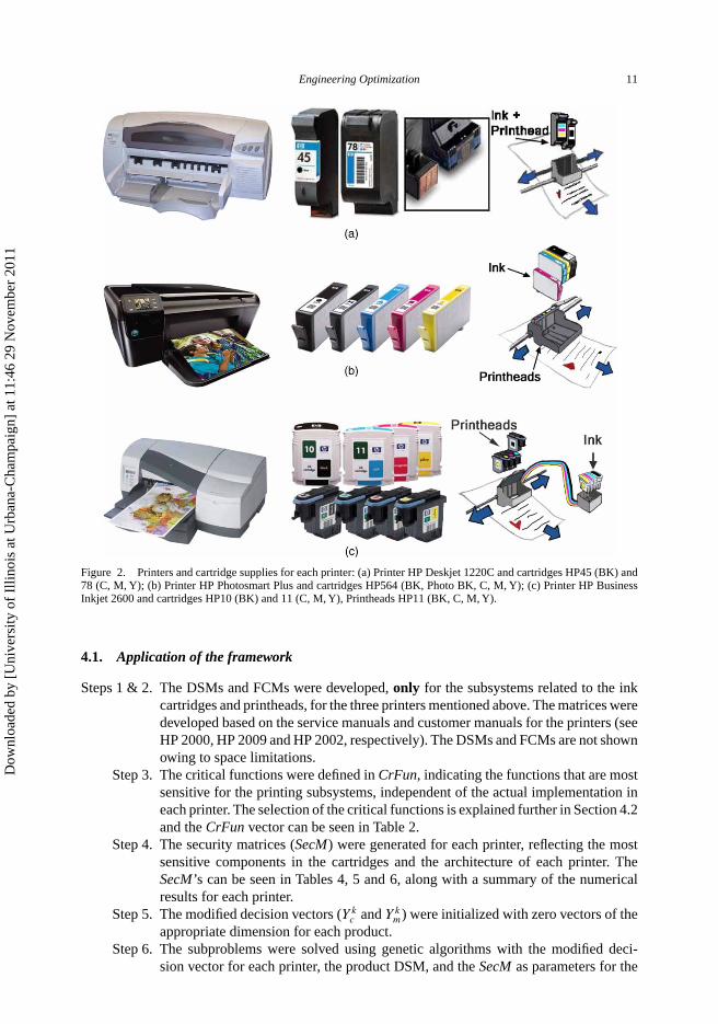
The framework discussed in the previous section is applied to analysing HP inkjet cartridges andtheir architecture for three distinct printers: the HP DeskJet 1220C; the HP Photosmart Plus; andthe HP Business Inkjet 2600 (see Figure 2).
These three printers exemplify the three strategies that HP currently uses for inkjet cartridgedesign: the first uses black (BK) and tricolour – cyan (C), magenta (M) and yellow (Y) – cartridgesthat include the printhead; the second uses individual ink cartridges for each colour but theprinthead is fixed to the printer; the last printer uses individual ink cartridges as well as printheadsthat are replaceable separately. The supplies for each printer are shown in Figure 2, as wellas diagrams that show the ink cartridges, printheads and carriages. This figure also shows thedirection in which the compartment moves and the elements that are carried by it, and how theprinting media pass by the printheads. These diagrams do not include the body of the printer orany subsystem other than the elements mentioned above, clarifying the difference in architectureof the three printers.
Each architecture is significantly different and includes distinctive features depending on theintended market for that product. The Deskjet printer is intended for basic colour printing for auser at home or in an office; the Photosmart is directed to users who require to print photos aswell as documents, but not at a professional level; lastly, the business inkjet is intended for highervolumes of colour printing in an office.
In a recent market report, Gartner Inc. affirms that printer OEMs (Original Equipment Man-ufacturers) could lose more than $13 billion to third-party manufacturers of supplies betweenmid-2009 and mid-2010 (Gartner 2009). This potential loss puts in perspective the importance forOEMs to secure their products and prevent third-party manufacturers or remanufacturers copyingtheir intellectual property.
Dow
nloa
ded
by [
Uni
vers
ity o
f Il
linoi
s at
Urb
ana-
Cha
mpa
ign]
at 1
1:46
29
Nov
embe
r 20
11
Engineering Optimization 11
Figure 2. Printers and cartridge supplies for each printer: (a) Printer HP Deskjet 1220C and cartridges HP45 (BK) and78 (C, M, Y); (b) Printer HP Photosmart Plus and cartridges HP564 (BK, Photo BK, C, M, Y); (c) Printer HP BusinessInkjet 2600 and cartridges HP10 (BK) and 11 (C, M, Y), Printheads HP11 (BK, C, M, Y).
4.1. Application of the framework
Steps 1 & 2. The DSMs and FCMs were developed, only for the subsystems related to the inkcartridges and printheads, for the three printers mentioned above. The matrices weredeveloped based on the service manuals and customer manuals for the printers (seeHP 2000, HP 2009 and HP 2002, respectively). The DSMs and FCMs are not shownowing to space limitations.
Step 3. The critical functions were defined in CrFun, indicating the functions that are mostsensitive for the printing subsystems, independent of the actual implementation ineach printer. The selection of the critical functions is explained further in Section 4.2and the CrFun vector can be seen in Table 2.
Step 4. The security matrices (SecM) were generated for each printer, reflecting the mostsensitive components in the cartridges and the architecture of each printer. TheSecM’s can be seen in Tables 4, 5 and 6, along with a summary of the numericalresults for each printer.
Step 5. The modified decision vectors (Y kc and Y k
m) were initialized with zero vectors of theappropriate dimension for each product.
Step 6. The subproblems were solved using genetic algorithms with the modified deci-sion vector for each printer, the product DSM, and the SecM as parameters for the
Dow
nloa
ded
by [
Uni
vers
ity o
f Il
linoi
s at
Urb
ana-
Cha
mpa
ign]
at 1
1:46
29
Nov
embe
r 20
11

12 A.J. Rojas Arciniegas and H.M. Kim
Table 2. Critical functions for the printing subsystem.
optimization. The optimal clustering strategy for each product was returned as theoptimal chromosome (Xk) according to Equation (12), which captures connectivity,component sharing and security restrictions.
Step 7. The optimal chromosomes from all products were passed to the master problemas parameters and the component sharing selection algorithm was executed. Thethreshold value for the IM was set at 1.0 for this example. The decision vectors (Y k)
were returned for each product and can be seen in Tables 4, 5 and 6.Step 8. The modified decision vectors (Y k
c and Y km) were obtained according to
Equation (11).Step 9. The tolerance for the stopping criteria, in this case, was selected to be zero (ε = 0).
Having this tolerance, Steps 6 to 8 were repeated for two iterations, after whichthere was no change in any decision vector.
4.2. Identifying the critical functions
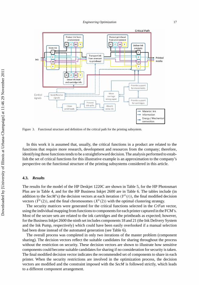
In order to establish the security restrictions in all three printers it was necessary to identifythe critical functions of the printing subsystem. First, the functional structure was examineddesignating the flow of information, energy and material through the printing system. The list offunctions came from the FCMs since that is a set of functions considered for all printers and theyare independent of the physical implementation of the individual products.
In Figure 3 the functional structure reflects how the functions involved in handling the ink andtaking each colour from the reservoirs to the paper in a precise manner were the most criticalfunctions in this subsystem. Therefore, these functions are designated as critical functions in thevector CrFun (see Table 2), which is later used to generate the security matrices for each printer(SecMk).
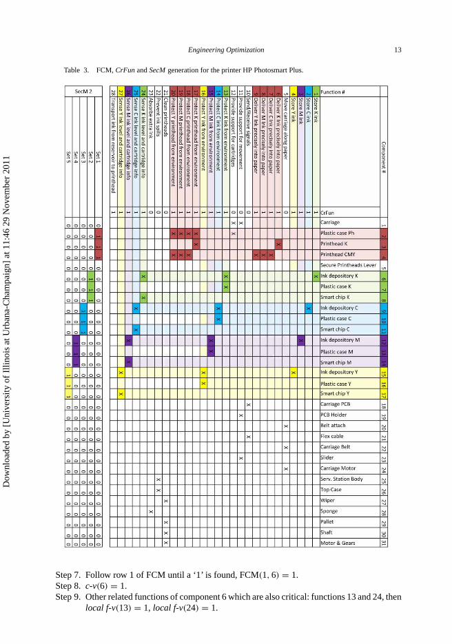
Table 3 shows how the critical functions are related to the components of the printer HPPhotosmart Plus, generating the security matrix (SecM2), which is composed of five restrictedsets, the first related to the printheads and the remaining four related to the individual ink cartridges.The generation of this SecM was as follows.
Step 1. i = 0 and master f-v = 0 (0 is the zero vector of nf elements).Step 2. Is function i critical? CrFun(1) = 1.Step 3. Is master f-v(i) = 1? master f-v(1) = 0, then continue.Step 4. master f-v(1) = 1, local f-v = 0, and c-v = 0.Step 5. local f-v(1) = 1, t = i = 1.Step 6. Is local f-v(t) = 1? local f-v(1) = 1, then continue.
Dow
nloa
ded
by [
Uni
vers
ity o
f Il
linoi
s at
Urb
ana-
Cha
mpa
ign]
at 1
1:46
29
Nov
embe
r 20
11
Engineering Optimization 13
Table 3. FCM, CrFun and SecM generation for the printer HP Photosmart Plus.
Step 7. Follow row 1 of FCM until a ‘1’ is found, FCM(1, 6) = 1.Step 8. c-v(6) = 1.Step 9. Other related functions of component 6 which are also critical: functions 13 and 24, then
local f-v(13) = 1, local f-v(24) = 1.
Dow
nloa
ded
by [
Uni
vers
ity o
f Il
linoi
s at
Urb
ana-
Cha
mpa
ign]
at 1
1:46
29
Nov
embe
r 20
11

14 A.J. Rojas Arciniegas and H.M. Kim
Table 4. Results summary for the printer HP Photosmart Plus.
Dow
nloa
ded
by [
Uni
vers
ity o
f Il
linoi
s at
Urb
ana-
Cha
mpa
ign]
at 1
1:46
29
Nov
embe
r 20
11
Engineering Optimization 15
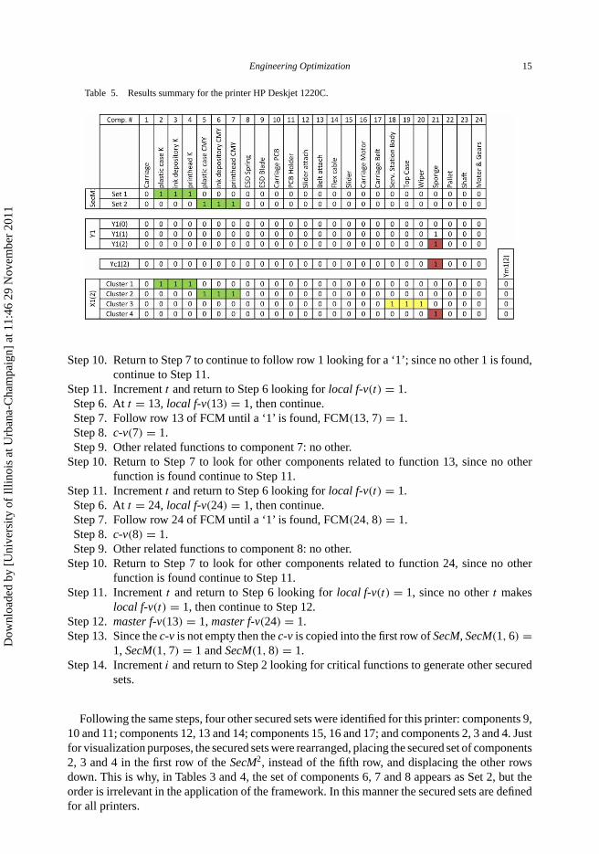
Table 5. Results summary for the printer HP Deskjet 1220C.
Step 10. Return to Step 7 to continue to follow row 1 looking for a ‘1’; since no other 1 is found,continue to Step 11.
Step 11. Increment t and return to Step 6 looking for local f-v(t) = 1.Step 6. At t = 13, local f-v(13) = 1, then continue.Step 7. Follow row 13 of FCM until a ‘1’ is found, FCM(13, 7) = 1.Step 8. c-v(7) = 1.Step 9. Other related functions to component 7: no other.
Step 10. Return to Step 7 to look for other components related to function 13, since no otherfunction is found continue to Step 11.
Step 11. Increment t and return to Step 6 looking for local f-v(t) = 1.Step 6. At t = 24, local f-v(24) = 1, then continue.Step 7. Follow row 24 of FCM until a ‘1’ is found, FCM(24, 8) = 1.Step 8. c-v(8) = 1.Step 9. Other related functions to component 8: no other.
Step 10. Return to Step 7 to look for other components related to function 24, since no otherfunction is found continue to Step 11.
Step 11. Increment t and return to Step 6 looking for local f-v(t) = 1, since no other t makeslocal f-v(t) = 1, then continue to Step 12.
Step 12. master f-v(13) = 1, master f-v(24) = 1.Step 13. Since the c-v is not empty then the c-v is copied into the first row of SecM, SecM(1, 6) =
1, SecM(1, 7) = 1 and SecM(1, 8) = 1.Step 14. Increment i and return to Step 2 looking for critical functions to generate other secured
sets.
Following the same steps, four other secured sets were identified for this printer: components 9,10 and 11; components 12, 13 and 14; components 15, 16 and 17; and components 2, 3 and 4. Justfor visualization purposes, the secured sets were rearranged, placing the secured set of components2, 3 and 4 in the first row of the SecM2, instead of the fifth row, and displacing the other rowsdown. This is why, in Tables 3 and 4, the set of components 6, 7 and 8 appears as Set 2, but theorder is irrelevant in the application of the framework. In this manner the secured sets are definedfor all printers.
Dow
nloa
ded
by [
Uni
vers
ity o
f Il
linoi
s at
Urb
ana-
Cha
mpa
ign]
at 1
1:46
29
Nov
embe
r 20
11

16 A.J. Rojas Arciniegas and H.M. Kim
Table 6. Results summary for the printer HP Business Inkjet 2600.
Dow
nloa
ded
by [
Uni
vers
ity o
f Il
linoi
s at
Urb
ana-
Cha
mpa
ign]
at 1
1:46
29
Nov
embe
r 20
11
Engineering Optimization 17
Figure 3. Functional structure and definition of the critical path for the printing subsystem.
In this work it is assumed that, usually, the critical functions in a product are related to thefunctions that require more research, development and resources from the company; therefore,identifying those functions tends to be a straightforward decision. The analysis performed to estab-lish the set of critical functions for this illustrative example is an approximation to the company’sperspective on the functional structure of the printing subsystems considered in this article.
4.3. Results
The results for the model of the HP Deskjet 1220C are shown in Table 5, for the HP PhotosmartPlus are in Table 4, and for the HP Business Inkjet 2600 are in Table 6. The tables include (inaddition to the SecM’s) the decision vectors at each iteration (Y k(t)), the final modified decisionvectors (Y k(2)), and the final chromosomes (Xk(2)) with the optimal clustering strategy.
The security matrices were generated for the critical functions selected in the CrFun vector,using the individual mapping from functions to components for each printer captured in the FCM’s.Most of the secure sets are related to the ink cartridges and the printheads as expected; however,for the Business Inkjet 2600 the ninth set includes components 18 and 21 (the Ink Delivery Systemand the Ink Pump, respectively) which could have been easily overlooked if a manual selectionhad been done instead of the automated generation (see Table 6).
The overall process was completed in only two iterations of the master problem (componentsharing). The decision vectors reflect the suitable candidates for sharing throughout the processwithout the restriction on security. These decision vectors are shown to illustrate how sensitivecomponents could become suitable candidates for sharing if no consideration for security is taken.The final modified decision vector indicates the recommended set of components to share in eachprinter. When the security restrictions are involved in the optimization process, the decisionvectors are modified and the constraint imposed with the SecM is followed strictly, which leadsto a different component arrangement.
Dow
nloa
ded
by [
Uni
vers
ity o
f Il
linoi
s at
Urb
ana-
Cha
mpa
ign]
at 1
1:46
29
Nov
embe
r 20
11

18 A.J. Rojas Arciniegas and H.M. Kim
The restricted sets from the SecM’s appear preserved in the optimal clusters of each printer (seeTables 4, 5 and 6). One of the components to share is common for the three printers, the Sponge;some other components are shared only between two of the printers. The set of components toshare between printers 2 (Photosmart Plus) and 3 (Business Inkjet 2600) include the CarriageBelt, the Belt Attach, and the Carriage Motor. These components are not sensitive and are notrestricted by the sets defined. However, the ink cartridges are also candidates for sharing betweenthese two printers, which are sensitive components. Sharing these elements is done in modulesrather than the individual components; therefore, all the components in the restricted set shouldbe candidates for sharing, which is the case for the ink cartridges.
Cluster 3 of printer 1 does not include any sensitive element or candidate for sharing, butcorresponds to an optimal arrangement according to the connectivity of the system; thence, it ispreserved by the algorithm.
When security restrictions were not considered (strictly following the framework in RojasArciniegas and Kim 2011), the results showed a more complicated module definition in the sensethat some modules overlap to minimize mismatches of types I and II; however, when securityis taken into account, the overlap is forbidden by the constraints in SecM or some modulesbreak down leading to a simpler structure but greater mismatches of types I and II. The maindifference was that the carriage of each printer was integrated with the components that constitutethe cartridges or the printheads. (The results of this analysis following Rojas Arciniegas and Kim2011 are not shown in this article owing to space limitations.) These results confirm how thesecurity considerations affect the architecture of the product, and how the framework presentedin this article, allows the designers to define sets of components that are known to be sensitiveand therefore need to be enclosed in a module.
5. Conclusion and future work
The methodology proposed in this article takes component/module security into considerationsfor component sharing and optimal architecture decision making in a family of products.
This new security criterion affects significantly the outcome of the optimal component sharingdecision making process in two ways. First, it preserves the restricted sets of components togetherwhile achieving optimal architecture. This may involve adding related components to the restrictedsets to form a cluster, or even joining restricted sets into a bigger cluster, as long as it contributesto achieving optimal architecture. Second, it prevents the sensitive components from becomingcandidates for sharing due to security concerns defined by the manufacturer. Instead, the sensitivecomponents are allowed to be shared only as modules confined within the restricted set(s).
The illustration design example of an inkjet printer family shows how the security concern canbe preserved while allowing component sharing across multiple products. This example validatesthe proposed framework by obtaining a different product architecture that considers both thesecurity of the sensitive components and component sharing among the three printers. The resultswere compared against the application of a similar framework without the security considerations(although it is not shown owing to space limitations) and not only were they different but theresults from the proposed framework reflect much more closely the actual implementation by HPand suggest which components could be shared.
It is not clear if the product architecture decisions that HP has made, at least for the threeprinters considered in this example, were indeed influenced by security considerations, but theycertainly make sense. The cartridge of the entry level printer (which is also the most probablecandidate for copying owing to high volume sales and high willingness from the user to buythe cheapest option) is the most complex type that they offer, enclosing the printhead as well asthe ink reservoir under the same case, making it more difficult to copy. On the other hand, the
Dow
nloa
ded
by [
Uni
vers
ity o
f Il
linoi
s at
Urb
ana-
Cha
mpa
ign]
at 1
1:46
29
Nov
embe
r 20
11

Engineering Optimization 19
high-end printer offers simpler cartridges that only contain the ink and a separate cartridge forthe printhead. This high-end type of printer is also intended for professional users, or at leastusers with very high concerns for quality and performance, who are less likely to buy third-partycartridges that may not meet the performance offered by the OEM.
Future work involves developing new representations with flexible degrees of security, whichwould capture security sensitive design decisions in a more comprehensive manner. These designdecisions involve evaluating the tradeoffs between compromising the security of the system andgaining the advantages of sharing components in a family of products, for which there is nomethodology established in the literature. Similarly, further research is necessary to expand thisframework to design products or subsystems that comply with the anti-tamper requirements forproducts or components that are not strictly software or electronics for military applications.
Acknowledgements
This material is based upon work supported by the National Science Foundation under CMMI 0726934. Any opinions,findings, conclusions or recommendations are those of the author(s) and do not necessarily reflect the views of the NationalScience Foundation.
References
Atallah, M.J., Bryant, E.D., and Stytz, M.R., 2004. A survey of anti-tamper technologies. CrossTalk: The Journal ofDefense Software Engineering, 17 (11), 12–16.
Baldwin, C.Y. and Clark, K.B., 2000. Design rules. Vol. 1. The power of modularity. Cambridge, MA: MIT Press.Browning, T.R., 2001. Applying the design structure matrix to system decomposition and integration problems: a review
and new directions. IEEE Transactions on Engineering Management, 48 (3), 292–306.Browning, T.R. and Eppinger, S.D., 2002. Modeling impacts of process architecture on cost and schedule risk in product
development. IEEE Transactions on Engineering Management, 49 (4), 428–442.Dahmus, J.B. and Gutowski, T.G., 2007. What gets recycled: an information theory based model for product recycling.
Environmental Science and Technology, 41 (21), 7543–7550.Gartner, 2009. Marketing essentials: what printer OEMs must do to compete against low-cost remanufactured supplies.
Market report. Stamford, CT: Gartner Inc.Harston, S.P. and Mattson, C.A., 2009. Metrics for evaluating and optimizing the barrier and time to reverse engineer
a product. In: Proceedings of the ASME 2009 international design engineering technical conference (DETC2009-86781), 30 August–2 September 2009, San Diego, CA. New York: ASME.
HP, 2000. HP DeskJet 1220C Pro Series – service and support guide. Palo Alto, CA: Hewlett-Packard.HP, 2002. HP Business InkJet 2600 – service and support manual. Palo Alto, CA: Hewlett-Packard.HP, 2009. HP Photosmart Plus B209 Series – user manual. Palo Alto, CA: Hewlett-Packard.Hughes, D. and Shmatikov,V., 2004. Information hiding, anonymity and privacy: a modular approach. Journal of Computer
Security, 12 (1), 3–36.Keller, J., 2009. It is time to take anti-tamper technology seriously. Military and Aerospace Electronics, 20 (2), 4.Khajavirad, A. and Michalek, J., 2008. A decomposed gradient-based approach for generalized platform selection and
variant design in product family optimization. Journal of Mechanical Design, 130 (7), 071101-1–071101-8.Khajavirad, A., Michalek, J., and Simpson, T., 2009. An efficient decomposed multiobjective genetic algorithm for solving
the joint product platform selection and product family design problem with generalized commonality. Structuraland Multidisciplinary Optimization, 39 (2), 187–201.
Kwak, M., Cho, N.W., and Hong, Y.S., 2007. Eco-architecture analysis as a method of end-of-life decision making forsustainable product design. In: Proceedings of the ASME 2007 international design engineering technical conference,4–7 September 2007, Las Vegas, NV. Vol. 3A. New York: ASME.
Legrand, 2007. The PDS dilemma: achieving modularity and scalability in protected distribution systems withoutcompromising security. White paper. Richmond, BC: Wiremold/Legrand.
Martin, M. and Ishii, K., 2002. Design for variety: developing standardized and modularized product platform architectures.Research in Engineering Design, 13 (4), 213–235.
Meyer, M.H. and Lehnerd, A.P., 1997. The power of product platform: building value and cost leadership. New York:Free Press.
Moon, S.K., Simpson, T.W., and Kumara, S.R., 2008. A strategic module-based platform design method for developingcustomized products in dynamic and uncertain market environments. In: Proceedings of the ASME 2008 internationaldesign engineering technical conference, 3–6 August 2008, Brooklyn, NY. Vol. 4. New York: ASME.
O’Hearn, P.W.,Yang, H., and Reynolds, J.C., 2009. On the criteria to be used in decomposing systems into modules. ACMTransactions on Programming Languages and Systems, 31 (3), 1–50.
Dow
nloa
ded
by [
Uni
vers
ity o
f Il
linoi
s at
Urb
ana-
Cha
mpa
ign]
at 1
1:46
29
Nov
embe
r 20
11

20 A.J. Rojas Arciniegas and H.M. Kim
Pandey, V. and Thurston, D., 2008. Metric for disassembly and reuse: formulation and validation. In: Proceedings of theASME 2008 international design engineering technical conference, 3–6 August 2008, Brooklyn, NY. Vol. 4. NewYork: ASME.
Parnas, D.L., 1972. On the criteria to be used in decomposing systems into modules. Communications of the ACM, 15(12), 1053–1058.
Porter, R., et al., 2009. Dynamic polymorphic reconfiguration for anti-tamper circuits. In: 19th international conferenceon field programmable logic and applications (FPL 09), 31 August–2 September 2009, Prague. New York: IEEE,493–497.
Rojas, A.J. and Esterman, M., 2008. A measure of impact for platform changes. In: Proceedings of the ASME 2008international design engineering technical conference, 3–6 August 2010, Brooklyn, NY. Vol. 4. New York: ASME.
Rojas, A.J. and Kim, H.M., 2010. Incorporating security considerations into optimal product architecture and componentsharing decision in product family design. In: Proceedings of the ASME 2010 international design engineeringtechnical conference, 15–18 August 2010, Montreal, Quebec, Canada. New York: ASME.
Rojas Arciniegas, A.J. and Kim, H.M., 2011. Optimal component sharing in product family by simultaneous considerationof minimum description length and impact metric. Engineering Optimization, 43 (2), 175–192.
Simpson, T.W., 2004. Product platform design and customization: status and promise. Artificial Intelligence forEngineering Design, Analysis and Manufacturing, 18 (1), 3–20.
Steva, E.D., et al., 2006. Two methodologies for identifying product platform elements within an existing set of products.In: Proceedings of the ASME 2006 international design engineering technical conference, 10–13 September 2006,Philadelphia, PA. Vol. 4, 811–821. New York: ASME.
Steward, D., 1981. The design structure system: a method for managing the design of complex systems. IEEE Transactionson Engineering Management, 28 (3), 71–74.
Strawbridge, B., McAdams, D., and Stone, R.B., 2002. A computational approach to conceptual design. In: Proceedings ofthe ASME 2002 design engineering technical conference, 29 September–2 October 2002, Montreal, Quebec, Canada,Vol. 4, 15–25. New York: ASME.
Tucker, C.S. and Kim, H.M., 2008. Optimal product portfolio formulation by merging predictive data mining withmultilevel optimization. Journal of Mechanical Design, 130 (4), 041103-1-041103-15.
Ulrich, K.T., 1995. The role of product architecture in the manufacturing firm. Research Policy, 24 (3), 419–440.US-DoD, Anti-tamper [online]. Department of Defense. Available from: http://at.dod.mil/ [Accessed 24 May 2010].Wang, B. and Antonsson, E.K., 2004. Information measure for modularity in engineering design. In: Proceedings of the
ASME 2004 international design engineering technical conference, 28 September–2 October 2004, Salt Lake City,UT, Vol. 3, 449–458. New York: ASME.
Yu, T., Yassine, A., and Goldberg, D., 2007. An information theoretic method for developing modular architectures usinggenetic algorithms. Research in Engineering Design, 18 (2), 91–109.
Zacharias, N.A. and Yassine, A.A., 2007. Platform investment decisions in product family design. In: Proceedings of theASME 2007 international design engineering technical conference, 4–7 September 2007, Las Vegas, NV, Vol. 3A.New York: ASME.
Dow
nloa
ded
by [
Uni
vers
ity o
f Il
linoi
s at
Urb
ana-
Cha
mpa
ign]
at 1
1:46
29
Nov
embe
r 20
11