Embed Size (px)
Citation preview
1⁄1⁄1 4⁄4⁄ ”-20 X 3⁄3⁄3 8⁄8⁄ ”SOCKET HEAD SCREWS
4” FENCE EXTENDER
EXTENDER BAR
”
FLUSH HERE
“SPECIAL EDITION” Telescoping Fence Addendum
Your new “Special Edition” INCRA Miter Gauge now includes a telescoping fence and Flip Shop Stop. These upgrades replace the fence and stop described in the owners’s manual. Follow the steps below to set up and use your telescoping fence.
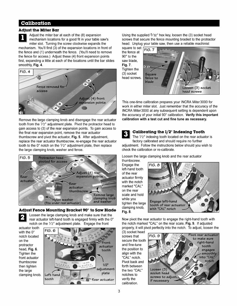
Fence Extender Assembly
Loosely install (1) 1⁄4⁄4⁄ -20 x 3⁄3⁄3 8⁄8⁄ ” socket head fastener with washer and rectangular nut to the left end of the fence and slide extender bar into fence with the scale face up. (The higher numbers on the scale should go in first.) Loosely install (2) 1⁄4⁄4⁄ -20 x 3⁄3⁄3 8⁄8⁄ ” socket head screws with washers and rectangular nuts to the 4” fence extender and slide onto the end of the extender bar. Position the 4” fence extender flush with the end of the extender bar and tighten all (3) fasteners, Fig 2.
2
Fence Extender Operation
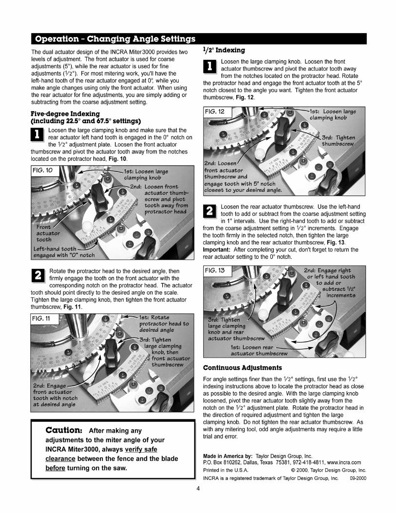
For stopped cuts beyond the range of the standard fence, clamp the INCRA Flip Shop Stop to the 4” fence extender. Now loosen the 1⁄1⁄1 4⁄4⁄ -20 socket head screw located at the left end of the fence and slide the 4” fence extender to the left. Tighten the fastener when you reach the desired scale reading. To set the scales for accurate readout, set the protractor to the desired angle, then measure the distance between the blade and the stop surface on the flip arm. Slide the scale to read this measurement directly under the end of the fence, Fig. 3. Slide the extender bar out to also adjust the overlapping scale if required.
3
092002
Made by: Taylor Design Group, Inc., P.O. Box 810262, Dallas, Texas 75381 Web Site: www.incra.com© 2002 Taylor Design Group, Inc. INCRA is a registered trademark of Taylor Design Group, Inc.
FIG. 2 FIG. 2
1
CLEARANCE
FIG. 1
CLEARANCECLEARANCECLEARANCECLEARANCE
1⁄4-20 X 1⁄2” SOCKET HEAD SCREWS
1111⁄1⁄1⁄111⁄1⁄⁄⁄⁄4⁄4⁄4⁄⁄⁄4⁄⁄1⁄⁄⁄1⁄4444-20 X 4-20 X ⁄4⁄⁄⁄⁄4⁄⁄⁄4⁄444⁄4⁄4⁄⁄⁄4⁄4⁄4⁄⁄⁄4⁄ -20 X -20 X -20 X -20 X 1111⁄1⁄1⁄111⁄1⁄⁄⁄⁄2⁄2⁄2⁄⁄⁄2⁄⁄1⁄⁄⁄1⁄2222” 2” ⁄2⁄2⁄222⁄2” ” ” ” SOCKET HEAD SOCKET HEAD SOCKET HEAD SOCKET HEAD SCREWSSCREWSSCREWSSCREWS
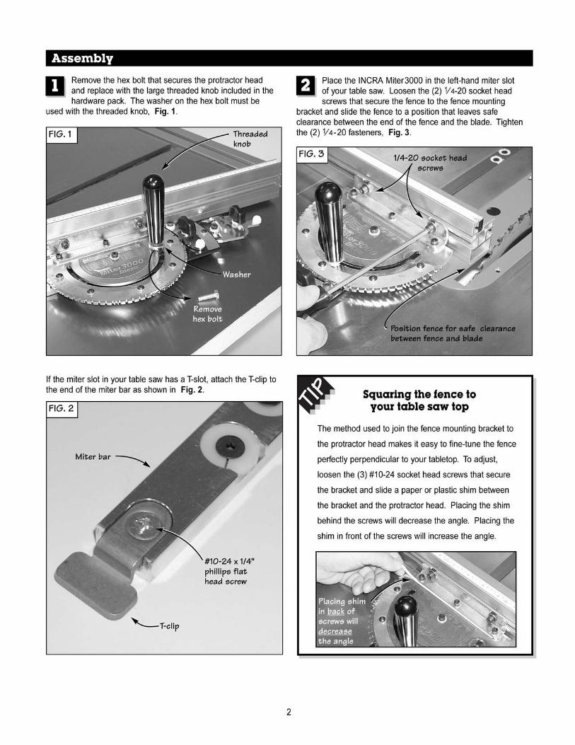
Attach Fence to Miter Gauge
Using the (2) 1⁄4⁄4⁄ -20 x 1⁄2⁄2⁄ ” socket head screws with washers and rectangular nuts, attach the fence to the fence mounting bracket. Slide the fence to a position that leaves safe clearance between the fence and blade, then tighten the (2) fasteners, Fig.-1.
FIG. 3 READ SCALE HERE
SLIDE SCALE TO READ BLADE TO STOP MEASUREMENT
READ SCALE READ SCALE SCALE HERESCALE HEREHERE
17/64” HOLE AT 9/16” FROM EACHEND OF EXTRUSION
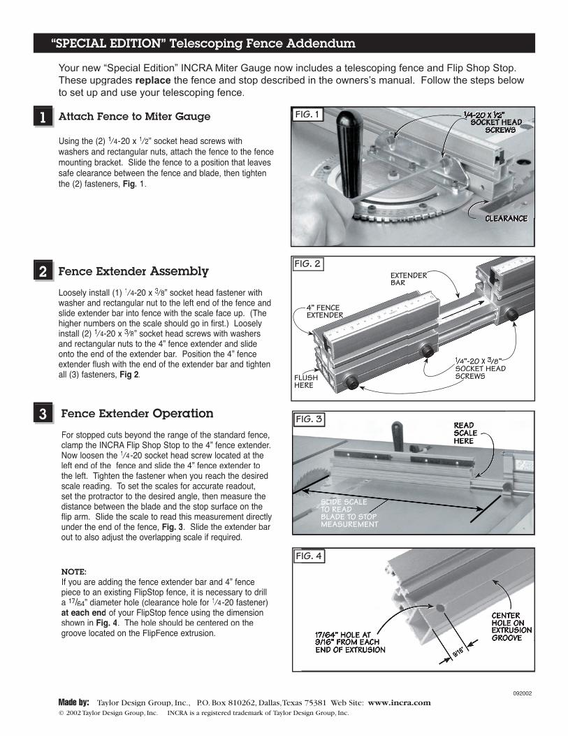
NOTE: If you are adding the fence extender bar and 4” fence piece to an existing FlipStop fence, it is necessary to drill a 17/17/17 64/64/ ” diameter hole (clearance hole for 1⁄1⁄1 4⁄4⁄ -20 fastener) at each end of your FlipStop fence using the dimension shown in Fig. 4. The hole should be centered on the groove located on the FlipFence extrusion.
FIG. 4
9/16”
CENTER HOLE ON EXTRUSION GROOVE
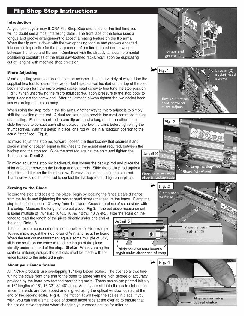
Introduction
As you look at your new IncrA Flip Shop Stop and fence for the first time you will no doubt see a most interesting detail. The front face of the fence uses a tongue and groove arrangement to accept a mating feature on the flip arms. When the flip arm is down with the two opposing tongue and grooves engaged, it becomes impossible for the sharp corner of a mitered board end to wedge between the fence and flip arm. combined with the already famous incremental positioning capabilities of the Incra saw-toothed racks, you'll soon be duplicating cut off lengths with machine shop precision.
Micro Adjusting
Micro adjusting your stop position can be accomplished in a variety of ways. Use the supplied hex tool to loosen the two socket head screws located on the top of the stop body and then turn the micro adjust socket head screw to fine tune the stop position. Fig 1. When unscrewing the micro adjust screw, apply pressure to the stop body to keep it against the screw end. After adjustment, always tighten the two socket head screws on top of the stop body.
When using the stop rods in the flip arms, another way to micro adjust is to simply shift the position of the rod. A dual rod setup can provide the most controlled means of adjusting. Place a short rod in one flip arm and a long rod in the other, then slide the rods to contact each other between the two flip arms before tightening the thumbscrews. With this setup in place, one rod will be in a "backup" position to the actual "stop" rod. Fig. 2.
To micro adjust the stop rod forward, loosen the thumbscrew that secures it and place a shim or spacer, equal in thickness to the adjustment required, between the backup and the stop rod. Slide the stop rod against the shim and tighten the thumbscrew. Detail 2.
To micro adjust the stop rod backward, first loosen the backup rod and place the shim or spacer between the backup and stop rods. Slide the backup rod against the shim and tighten the thumbscrew. remove the shim, loosen the stop rod thumbscrew, slide the stop rod to contact the backup rod and tighten in place.
Zeroing to the Blade
To zero the stop and scale to the blade, begin by locating the fence a safe distance from the blade and tightening the socket head screws that secure the fence. clamp the stop to the fence about 10" away from the blade. crosscut a piece of scrap stock with this setup. Measure the length of the cut piece. Fig 3. If the cut piece measurement is some multiple of 1⁄32" (i.e.: 101⁄32, 101⁄16, 103⁄32, 101⁄8 etc.), slide the scale on the fence to read the length of the piece directly under one end of the stop. Detail 3.If the cut piece measurement is not a multiple of 1⁄32 (example: 101⁄64), micro adjust the stop forward 1⁄64", and recut the board. When the test cut measurement equals some multiple of 1⁄32", slide the scale on the fence to read the length of the piece directly under one end of the stop. Note: When zeroing the scale for mitering setups, the test cuts must be made with the fence locked to the selected angle.
About your Fence Scales
All IncrA products use overlapping 16" long Lexan scales. The overlap allows fine- tuning the scale from one end to the other to agree with the high degree of accuracy provided by the Incra saw toothed positioning racks. These scales are printed initially in 16" lengths (0-16", 16-32", 32-48" etc.). As they are slid into the scale slot on the fence, the ends are overlapped and aligned using the optical window located at the end of the second scale. Fig 4. The friction fit will keep the scales in place. If you wish, you can use a small piece of double faced tape at the overlap to ensure that the scales move together when changing your zeroed setups for mitering.
Flip Shop Stop Instructions
Fig. 1
Fig. 2
Detail 2
Fig. 3
Detail 3
Fig. 4
Loosen (2) socket head screws
Turn this socket head screw to micro adjust
Short “stop” rodPlace shim between stop & backup rods
Measure test cut length
Clamp stop to fence
Long “backup” rod
Slide scale to read board’s length under either end of stop
Align scales using optical window
Tongue and groove
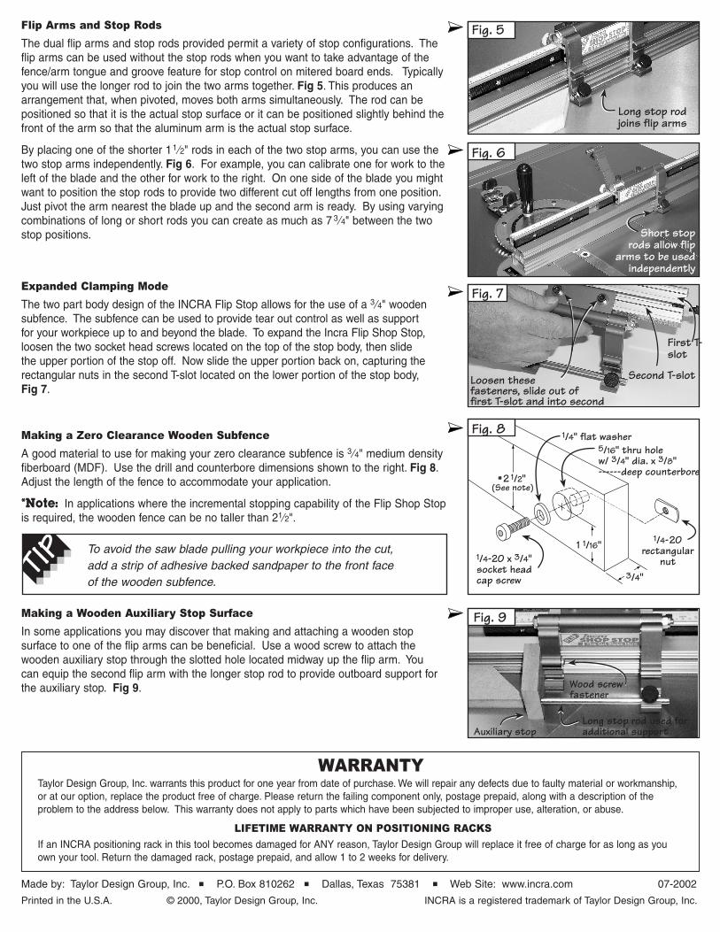
Flip Arms and Stop Rods
The dual flip arms and stop rods provided permit a variety of stop configurations. The flip arms can be used without the stop rods when you want to take advantage of the fence/arm tongue and groove feature for stop control on mitered board ends. Typically you will use the longer rod to join the two arms together. Fig 5. This produces an arrangement that, when pivoted, moves both arms simultaneously. The rod can be positioned so that it is the actual stop surface or it can be positioned slightly behind the front of the arm so that the aluminum arm is the actual stop surface.
By placing one of the shorter 11⁄2" rods in each of the two stop arms, you can use the two stop arms independently. Fig 6. For example, you can calibrate one for work to the left of the blade and the other for work to the right. On one side of the blade you might want to position the stop rods to provide two different cut off lengths from one position. Just pivot the arm nearest the blade up and the second arm is ready. By using varying combinations of long or short rods you can create as much as 7 3⁄4" between the two stop positions.
Expanded Clamping Mode
The two part body design of the IncrA Flip Stop allows for the use of a 3⁄4" wooden subfence. The subfence can be used to provide tear out control as well as support for your workpiece up to and beyond the blade. To expand the Incra Flip Shop Stop, loosen the two socket head screws located on the top of the stop body, then slide the upper portion of the stop off. now slide the upper portion back on, capturing the rectangular nuts in the second T-slot located on the lower portion of the stop body, Fig 7.
Making a Zero Clearance Wooden Subfence
A good material to use for making your zero clearance subfence is 3⁄4" medium density fiberboard (MDF). Use the drill and counterbore dimensions shown to the right. Fig 8. Adjust the length of the fence to accommodate your application.
*Note: In applications where the incremental stopping capability of the Flip Shop Stop is required, the wooden fence can be no taller than 21⁄2".
Made by: Taylor Design Group, Inc. ■ P.O. Box 810262 ■ Dallas, Texas 75381 ■ Web Site: www.incra.com 07-2002
Printed in the U.S.A. © 2000, Taylor Design Group, Inc. IncrA is a registered trademark of Taylor Design Group, Inc.
WARRAntyTaylor Design Group, Inc. warrants this product for one year from date of purchase. We will repair any defects due to faulty material or workmanship, or at our option, replace the product free of charge. Please return the failing component only, postage prepaid, along with a description of the problem to the address below. This warranty does not apply to parts which have been subjected to improper use, alteration, or abuse.
LIFEtIME WARRAnty On POSItIOnInG RACKS
If an IncrA positioning rack in this tool becomes damaged for AnY reason, Taylor Design Group will replace it free of charge for as long as you own your tool. return the damaged rack, postage prepaid, and allow 1 to 2 weeks for delivery.
Making a Wooden Auxiliary Stop Surface
In some applications you may discover that making and attaching a wooden stop surface to one of the flip arms can be beneficial. Use a wood screw to attach the wooden auxiliary stop through the slotted hole located midway up the flip arm. You can equip the second flip arm with the longer stop rod to provide outboard support for the auxiliary stop. Fig 9.
To avoid the saw blade pulling your workpiece into the cut, add a strip of adhesive backed sandpaper to the front face of the wooden subfence.
1 1/16"1/4-20 x 3/4" socket head cap screw
1/4" flat washer
3/4"
5/16" thru hole w/ 3/4" dia. x 3/8" ------deep counterbore
1/4-20 rectangular
nut
(See note)*2 1/2"
Fig. 5
Fig. 6
Fig. 7
Fig. 8
Fig. 9
Long stop rod joins flip arms
Short stop rods allow flip
arms to be used independently
Second T-slot
First T-slot
Loosen these fasteners, slide out of first T-slot and into second
Wood screw fastener
Auxiliary stopLong stop rod used for additional support