Embed Size (px)
Citation preview
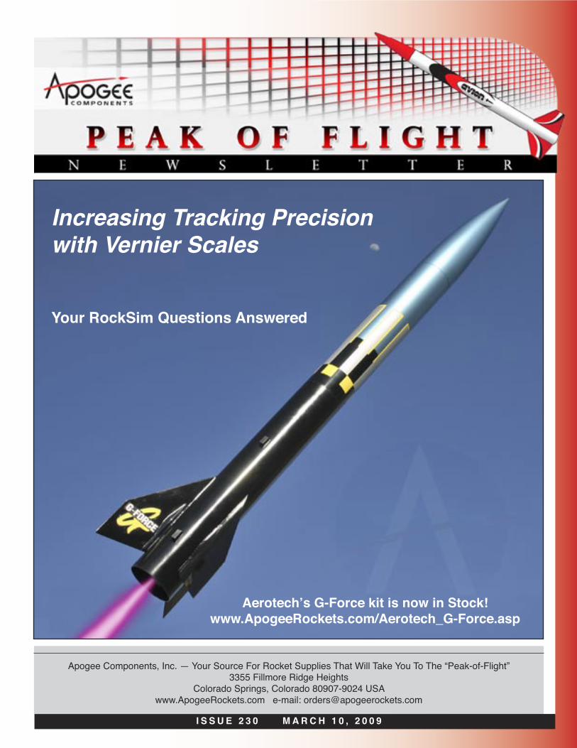
I S S U E 2 3 0 M A R C H 1 0 , 2 0 0 9
Apogee Components, Inc. — Your Source For Rocket Supplies That Will Take You To The “Peak-of-Flight”3355 Fillmore Ridge Heights
Colorado Springs, Colorado 80907-9024 USAwww.ApogeeRockets.com e-mail: [email protected]
Increasing Tracking Precision with Vernier Scales
Aerotech’s G-Force kit is now in Stock!www.ApogeeRockets.com/Aerotech_G-Force.asp
Your RockSim Questions Answered
Page 2 I S S U E 2 3 0 M A R C H 1 0 , 2 0 0 9
You can subscribe to receive this e-zine FREE at the Apogee Components web site (www.ApogeeRockets.com), or by sending an e-mail to: [email protected] with “SUB-SCRIBE” as the subject line of the message.
About this Newsletter Newsletter Staff
Writer: Tim Van MilliganLayout / Cover Artist: Tim Van MilliganProofreader: Michelle Mason
By Bernard Herman
Continued on page 3
In Peak-of-Flight Newsletter 164 (www.ApogeeRock-ets.com/education/downloads/Newsletter164.pdf) I wrote about the precision of your readings for determining the height your rocket attained. In that article I mentioned creat-ing a vernier scale for your scopes to help make readings more precise. In issue 222 (www.ApogeeRockets.com/edu-cation/downloads/Newsletter222.pdf), Tim Van Milligan talked about finding the possible landing place of your lost rocket, and in Issue 223 (www.ApogeeRockets.com/educa-tion/downloads/Newsletter223.pdf) he talked about building a triangulation station scope. Well, to finally fulfill my prom-ise of the first article and to assist in the finding of your lost rockets, I have undertaken the writing of this article.
In the first part of this article, I will teach you how to use and read a vernier scale with the triangulation station scope shown in issue 223. In the second part, I will show you how to design and create a vernier scale of your own for your own particular tracking theodolite.
Increased Tracking Precision with Vernier Scales
Getting StartedThe first step in us-
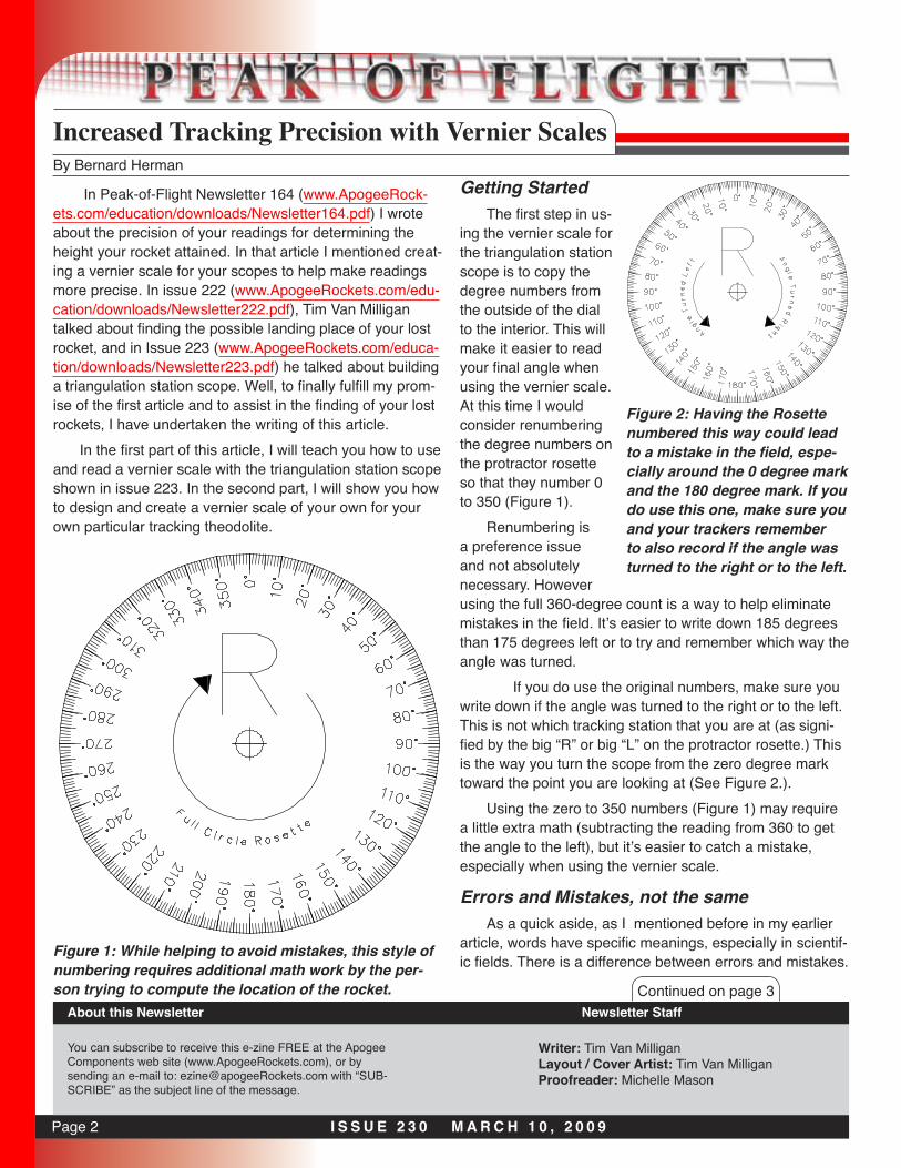
ing the vernier scale for the triangulation station scope is to copy the degree numbers from the outside of the dial to the interior. This will make it easier to read your final angle when using the vernier scale. At this time I would consider renumbering the degree numbers on the protractor rosette so that they number 0 to 350 (Figure 1).
Renumbering is a preference issue and not absolutely necessary. However using the full 360-degree count is a way to help eliminate mistakes in the field. It’s easier to write down 185 degrees than 175 degrees left or to try and remember which way the angle was turned.
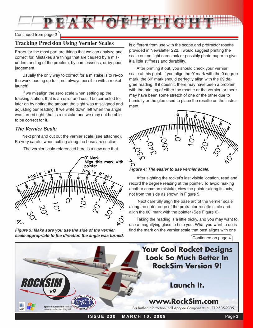
If you do use the original numbers, make sure you write down if the angle was turned to the right or to the left. This is not which tracking station that you are at (as signi-fied by the big “R” or big “L” on the protractor rosette.) This is the way you turn the scope from the zero degree mark toward the point you are looking at (See Figure 2.).
Using the zero to 350 numbers (Figure 1) may require a little extra math (subtracting the reading from 360 to get the angle to the left), but it’s easier to catch a mistake, especially when using the vernier scale.
Errors and Mistakes, not the sameAs a quick aside, as I mentioned before in my earlier
article, words have specific meanings, especially in scientif-ic fields. There is a difference between errors and mistakes.
Figure 2: Having the Rosette numbered this way could lead to a mistake in the field, espe-cially around the 0 degree mark and the 180 degree mark. If you do use this one, make sure you and your trackers remember to also record if the angle was turned to the right or to the left.
Figure 1: While helping to avoid mistakes, this style of numbering requires additional math work by the per-son trying to compute the location of the rocket.
Page 3I S S U E 2 3 0 M A R C H 1 0 , 2 0 0 9
Tracking Precision Using Vernier ScalesContinued from page 2
Errors for the most part are things that we can analyze and correct for. Mistakes are things that are caused by a mis-understanding of the problem, by carelessness, or by poor judgement.
Usually the only way to correct for a mistake is to re-do the work leading up to it, not always possible with a rocket launch!
If we misalign the zero scale when setting up the tracking station, that is an error and could be corrected for later on by noting the amount the sight was misaligned and adjusting our reading. If we write down left when the angle was turned right, that is a mistake and we may not be able to be correct for it.
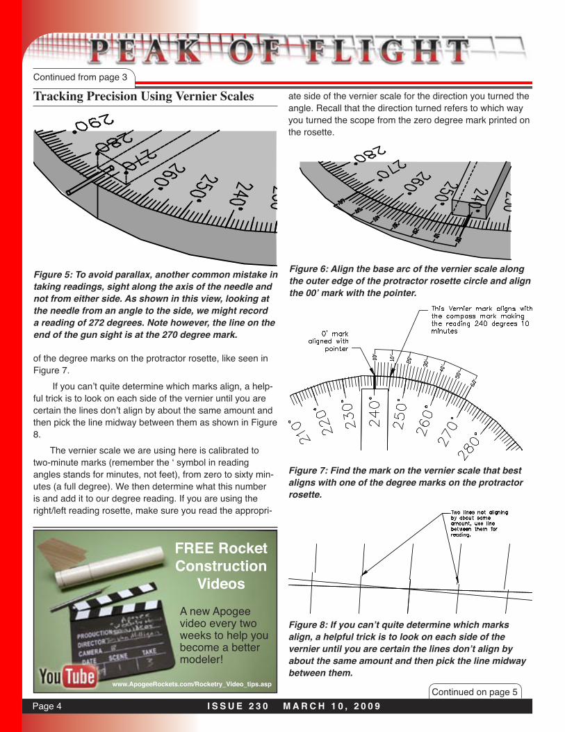
The Vernier ScaleNext print and cut out the vernier scale (see attached).
Be very careful when cutting along the base arc section. The vernier scale referenced here is a new one that
is different from use with the scope and protractor rosette provided in Newsletter 222. I would suggest printing the scale out on light cardstock or possibly photo paper to give it a little stiffness and durability.
After printing it out, you should check your vernier scale at this point. If you align the 0’ mark with the 0 degree mark, the 60’ mark should perfectly align with the 29 de-gree reading. If it doesn’t, there may have been a problem with the printing of either the rosette or the vernier, or there may have been some stretch of one or the other due to humidity or the glue used to place the rosette on the instru-ment.
Space Foundation certified as an excellent teaching aid. For further information, call Apogee Components at: 719-535-9335.
www.RockSim.comv9
Your Cool Rocket Designs Look So Much Better In
RockSim Version 9!
Launch It.
Continued on page 4
Figure 3: Make sure you use the side of the vernier scale appropriate to the direction the angle was turned.
After sighting the rocket’s last visible location, read and record the degree reading at the pointer. To avoid making another common mistake, view the pointer along its axis, not from the side as shown in Figure 5.
Next carefully align the base arc of the vernier scale along the outer edge of the protractor rosette circle and align the 00’ mark with the pointer (See Figure 6).
Taking the reading is a little tricky, and you may want to use a magnifying glass to help you. What you want to do is find the mark on the vernier scale that best aligns with one
Figure 4: The easier to use vernier scale.
Page 4 I S S U E 2 3 0 M A R C H 1 0 , 2 0 0 9Continued on page 5
of the degree marks on the protractor rosette, like seen in Figure 7.
If you can’t quite determine which marks align, a help-ful trick is to look on each side of the vernier until you are certain the lines don’t align by about the same amount and then pick the line midway between them as shown in Figure 8.
The vernier scale we are using here is calibrated to two-minute marks (remember the ‘ symbol in reading angles stands for minutes, not feet), from zero to sixty min-utes (a full degree). We then determine what this number is and add it to our degree reading. If you are using the right/left reading rosette, make sure you read the appropri-
Tracking Precision Using Vernier ScalesContinued from page 3
Figure 5: To avoid parallax, another common mistake in taking readings, sight along the axis of the needle and not from either side. As shown in this view, looking at the needle from an angle to the side, we might record a reading of 272 degrees. Note however, the line on the end of the gun sight is at the 270 degree mark.
FREE RocketConstruction
VideosA new Apogee video every two weeks to help you become a better modeler!
www.ApogeeRockets.com/Rocketry_Video_tips.asp
Figure 6: Align the base arc of the vernier scale along the outer edge of the protractor rosette circle and align the 00’ mark with the pointer.
Figure 8: If you can’t quite determine which marks align, a helpful trick is to look on each side of the vernier until you are certain the lines don’t align by about the same amount and then pick the line midway between them.
Figure 7: Find the mark on the vernier scale that best aligns with one of the degree marks on the protractor rosette.
ate side of the vernier scale for the direction you turned the angle. Recall that the direction turned refers to which way you turned the scope from the zero degree mark printed on the rosette.

Page 5I S S U E 2 3 0 M A R C H 1 0 , 2 0 0 9
ConclusionVernier scales have been around for a long time and
are not just used for angular readings. The vernier scale is a useful tool to help give us more precise readings and maybe, to help us find a lost rocket or determine which rocket flew higher.
Like with all tools, a little care and understanding of how it functions are needed. Figure 9 shows three exam-ples to test your ability to read vernier scales.
Remember that the vernier scale I have provided here can only be used with the protractor rosette for the trian-gulation tracking scope from Peak-of-Flight newsletter 223 (www.ApogeeRockets.com/education/downloads/News-letter223.pdf). You can download modified vernier scales attached to the rosettes at: www.ApogeeRockets.com/edu-cation/downloads/Vernier_Grids.pdf
About the Author:Bernie Herman has worked in the land surveying field
for over twenty years. He doesn’t consider himself a BAR since he never gave up rocketry since his mother bought him his first model rocket kit in 1973 at the age of ten. He has been married for over seventeen years. He has five children, three girls and two boys.
Tracking Precision Using Vernier ScalesContinued from page 4
Model Rocket Design and ConstructionBy Timothy S. Van Milligan
New 3rd Edition Now Shipping!
Apogee Components3355 Fillmore Ridge HeightsColorado Springs, Colorado 80907 USA
telephone: 719-535-9335website: www.ApogeeRockets.com
This new 328 page guidebook for serious rocket designers contains the most up-to-date information on creating unique and exciting models that re-ally work. With 566 illustrations and 175 photos, it is the ultimate resource if you want to make rockets that will push the edge of the performance envelope. Because of the number of pictures, it is also a great gift to give to beginners to start them on their rocketry future.
For more information, and to order this hefty book, visit the Apogee web site at: www.ApogeeRockets.com/design_book.asp
Figure 9 (Right): Some examples of vernier measure-ments to gain some practice making readings.
Page 6 I S S U E 2 3 0 M A R C H 1 0 , 2 0 0 9
By Tim Van Milligan
RockSim Questions and Answers
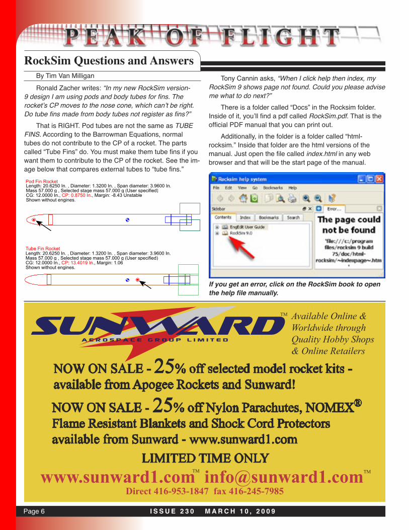
Ronald Zacher writes: “In my new RockSim version-9 design I am using pods and body tubes for fins. The rocket’s CP moves to the nose cone, which can’t be right. Do tube fins made from body tubes not register as fins?”
That is RIGHT. Pod tubes are not the same as TUBE FINS. According to the Barrowman Equations, normal tubes do not contribute to the CP of a rocket. The parts called “Tube Fins” do. You must make them tube fins if you want them to contribute to the CP of the rocket. See the im-age below that compares external tubes to “tube fins.”
Length: 20.6250 In. , Diameter: 1.3200 In. , Span diameter: 3.9600 In.Mass 57.000 g , Selected stage mass 57.000 g (User specified)CG: 12.0000 In., CP: 0.8750 In., Margin: -8.43 UnstableShown without engines.
Pod Fin Rocket
Tube Fin RocketLength: 20.6250 In. , Diameter: 1.3200 In. , Span diameter: 3.9600 In.Mass 57.000 g , Selected stage mass 57.000 g (User specified)CG: 12.0000 In., CP: 13.4019 In., Margin: 1.06Shown without engines.
Tony Cannin asks, “When I click help then index, my RockSim 9 shows page not found. Could you please advise me what to do next?”
There is a folder called “Docs” in the Rocksim folder. Inside of it, you’ll find a pdf called RockSim.pdf. That is the official PDF manual that you can print out.
Additionally, in the folder is a folder called “html-rocksim.” Inside that folder are the html versions of the manual. Just open the file called index.html in any web browser and that will be the start page of the manual.
If you get an error, click on the RockSim book to open the help file manually.
Available Online &Worldwide throughQuality Hobby Shops& Online Retailers
NOW ON SALE - 25% off selected model rocket kits - available from Apogee Rockets and Sunward!
TM
NOW ON SALE - 25% off Nylon Parachutes, NOMEX®
Flame Resistant Blankets and Shock Cord Protectorsavailable from Sunward - www.sunward1.com
www.sunward1.com [email protected] 416-953-1847 fax 416-245-7985
LIMITED TIME ONLYTM TM