Embed Size (px)
Citation preview

Incremental Signal-Tracingfor FPGA Debug
Eddie Hung, Steven J. E. Wilton{eddieh,stevew}@ece.ubc.ca
University of British ColumbiaVancouver, Canada
FPL :: Aug 2012

2
What this talk is about
● FPGAs have many advantages● Ability for “Desktop Fabrication”● Commonly used to prototype and verify ASICs

3
What this talk is about
● FPGAs have many advantages● Ability for “Desktop Fabrication”● Commonly used to prototype and verify ASICs
● But even so, debug is still hard!
Design Test Error !?!?

4
What this talk is about
● FPGAs have many advantages● Ability for “Desktop Fabrication”● Commonly used to prototype and verify ASICs
● But even so, debug is still hard!
● This work: Incremental techniques for trace-buffer insertion
Design Test Error !?!?

5
Introduction
● Debug is the process of locating and eliminating design errors – 'bugs' – in ICs
● Important as mistakes in silicon cost big money● 2007: AMD K10 TLB bug – 4 months● 2011: Intel 'Sandy Bridge' chipset – $700 million

6
Introduction
● Pre-Silicon techniques alone are insufficient● Software simulation effective, but slow
– Latest Core i7 (2.6 GHz) simulates at 2-3Hz
● Formal verification limited to small components● Unable to interact with real-world stimulus
● FPGA prototypes -- fast and physical● Instant circuit fabrication: quick turnaround● Runs at near-speed: increased coverage

7
Introduction
● For debug, same challenge as ASICs: visibility● Limited I/O: lack of access to internal nodes
Virtex(220nm)
Virtex-E(180nm)
Virtex II Pro(130nm)
Virtex 4(90nm)
Virtex 5(65nm)
Virtex 6(40nm)
Virtex 7(28nm)
0
500,000
1,000,000
1,500,000
2,000,000
2,500,000
0
400
800
1,200
1,600
2,000LogicI/O
Lo
gic
Cel
ls
Use
r I/
O

8
Introduction
● Enhance observability with trace-buffers: ● Sample a subset of signals into on-chip memories● Capturing a sequence of states, at full speed
PCExternalStimuli
Real-time data collection Off-line analysis
a
b
c
d
e
Waveform
Instrumented FPGA
FPGA
User Design
Trace BufferCtrl

9
Introduction
● Enhance observability with trace-buffers: ● Sample a subset of signals into on-chip memories● Capturing a sequence of states, at full speed
● Does not cost extra silicon area– FPGAs commonly not filled to capacity
● Example IP: Xilinx ChipScope, Altera SignalTap, Tektronix Certus

10
Incremental-Tracing
⇒ Faster debug turnaround
11
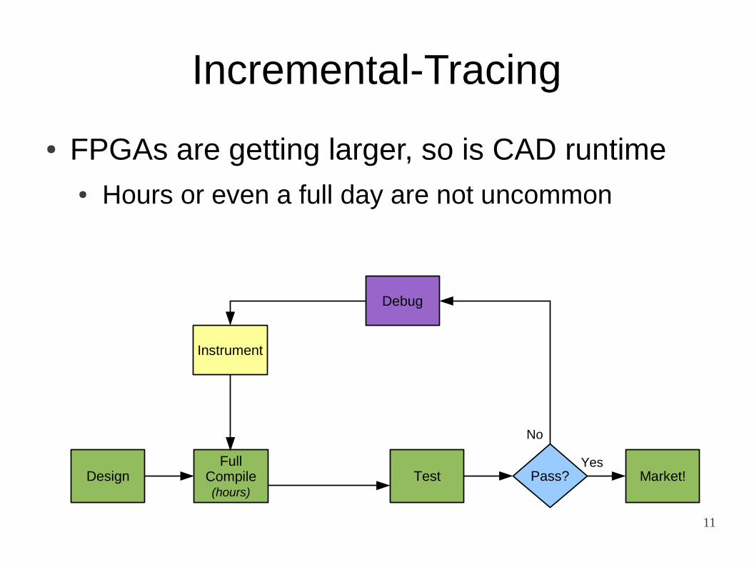
Incremental-Tracing
● FPGAs are getting larger, so is CAD runtime● Hours or even a full day are not uncommon
DesignFull
Compile(hours)
Test
Debug
Pass?
No
YesMarket!
Instrument

12
DesignFull
Compile(hours)
Test
Debug
Pass?
No
YesMarket!
Instrument
IncrementalCompile(minutes)
Incremental-Tracing
● FPGAs are getting larger, so is CAD runtime● Hours or even a full day are not uncommon
● Use Incremental-Compilation techniques!

13
Incremental-Tracing
● Incremental Compilation is not new...● Crucially: during debug, only want to observe● Instrument without modifying user-circuit
● Incrementally add trace connections using spare resources not used in the original circuit mapping
● Faster turnaround time between debug iterations● Preserve circuit mapping and avoid heuristic CAD
● But what are its limitations?

14
Incremental-Tracing CAD
● Two techniques to improve feasibility:● Many-to-many flexibility – connect to any trace-pin
M
M
MMemoryBlocks
(used/free)
LogicBlocks
(free/used)
IncrementalCompilation

15
Incremental-Tracing CAD
● Two techniques to improve feasibility:● Many-to-many flexibility – connect to any trace-pin
M
M
M
IncrementalCompilation

16
Incremental-Tracing CAD
● Two techniques to improve feasibility:● Many-to-many flexibility – connect to any trace-pin
M
M
M
IncrementalTracing

17
M
M
M
Incremental-Tracing CAD
● Two techniques to improve feasibility:● Many-to-many flexibility – connect to any trace-pin
IncrementalTracing

18
Incremental-Tracing CAD
● Two techniques to improve feasibility:● Many-to-many flexibility – connect to any trace-pin
M
M
M
T
IncrementalTracing

19
Incremental-Tracing CAD
● Two techniques to improve feasibility:● Many-to-many flexibility – connect to any trace-pin
T
T
T
M
M
M
T IncrementalTracing

20
Incremental-Tracing CAD
● Two techniques to improve feasibility:● Many-to-many flexibility – connect to any trace-pin● Logic element symmetry – leave from any OPIN
Logic Cluster 1
LocalRouting
LogicElement
LogicElement
LogicElement
A
B
C
OPIN
OPIN
OPIN
Global Routing

21
Incremental-Tracing CAD
● Two techniques to improve feasibility:● Many-to-many flexibility – connect to any trace-pin● Logic element symmetry – leave from any OPIN
Local Logic ElementsA and B can be swapped for free!
TraceBuffer
Logic Cluster 1
LocalRouting
LogicElement
LogicElement
LogicElement
A
B
C
OPIN
OPIN
OPIN
Global Routing

22
Limits to Incremental-Tracing
● Investigate using VPR6 (VTR)● Hetereogeneous architecture with hard-mul & RAM● Perform packing-placement-routing as normal● Randomly instrument results with trace-buffers
HDL sourcee.g. Verilog
LogicSynthesis
Packing &Placement Routing
Simple Logic Floorplan Floorplan w/ Routing
Incremental-Tracing
GenerateBitstream
VPR

23
Limits to Incremental-Tracing
● OPINs individually routable to any trace-pin
Minimum Channel Width(Routing Area)
(99700 6LUTs)
(1977 6LUTs)

24
Limits to Incremental-Tracing
● Percentage of selections completely trace-able
0 144 288 432 576 720 signals
or1200 (2963 6LUTs)
Solid Lines:With LE symmetry
Dotted Lines:Without LE symmetry
MinimumChannel
Width(Area)
Signals traced, normalized to memory capacity

25
Limits to Incremental-Tracing
● Percentage of selections completely trace-able
0 389 776 1166 1555 1944 signals
LU8PEEng (21954 6LUTs)
Dotted lines are without LE symmetry

26
Limits to Incremental-Tracing
● Runtime (75% trace demand):
Placement Runtime

27
Limits to Incremental-Tracing
● Effect on Critical Path Delay
Probability Affected
Average Increase
mkSMAdapter4B 11.9% 3.4%or1200 4.7% 3.6%mkDelayWorker32B 2.4% 3.6%LU8PEEng <0.1% 0.2%
28
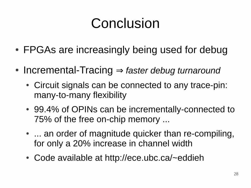
Conclusion
● FPGAs are increasingly being used for debug
● Incremental-Tracing faster debug turnaround⇒● Circuit signals can be connected to any trace-pin:
many-to-many flexibility
● 99.4% of OPINs can be incrementally-connected to 75% of the free on-chip memory ...
● ... an order of magnitude quicker than re-compiling, for only a 20% increase in channel width
● Code available at http://ece.ubc.ca/~eddieh