Embed Size (px)
Citation preview

INDE.PENDENTRES*EARCH
A NDINDEPENDENT
EXPLORAIDRYDEVELOPENT
AND FY10San Diego, Cslffornia 92152?TEON C HNCL!T~~OCYOUMENT 496
1 OCTOMER 1976

Apprved or ubl~ relae;
ditiuto.suniie
RPRCOTOSYBOLNVA 3-*-

This marks the ninth tR/IED report for the Naval Electronics Laboratory Center.In the last few years there has been strong emphasis toward developing both (1)new capabilities which will help us fulfill our role in prcvidlng the technological basefor new performance demands of the future and (2) improved ability to achievesignificant gains in equipment, reliability, and efficiency together with reduction inequipment size, weight, and life-cycle cost in the present. Examples of the first-category include fiber optics, optical communications, charge-coupled devices,new materials for field-effect transistors, and millimetre wave devices to 60 GHz.Ex, mples of the second category include digital techniques, modular approach toequiprr ents, application of medium-scale integration (MSI) and large-scaleirlegr.tion (LSI), microprocessors, and increased reliability through understandingof device fabrication and failure.
A main thrust has been toward electro-optics technology: laser research anddevelooment, optical signal processing, fiber and integrated optics, and opticalcommunications. As a result, there have been many advances that have presentard Potential value to the Navy. The Submarine-to-Aircraft OpticalCommunications System (SAOCS) is planned for advanced development in FY77to enter the Fleet about 1985. The real-time programmable electro-optical signalprocessor will be used in a bioacoustic communication study to be made jointlywith the Naval Undersea Center. A fiber optics system installed among the NORADcomputer complexes at Cheyenne Mountain, Colorado, has operated successfullyand paid for itself in 15 months.
Many fleet capabilities have their origins in IR/IED projects, as do manysignificant current development programs. Current NELC block programs also canbe traced back to earlier IR or lED projects.
co

I~iBlock Programs IRIlED Origins
Command Control Natural Language Processing;Network StudySmall Ship C2 SystemDisplay Studies
Communication HF-PropagationSignal Processing Theory
EO-Laser Physics and DevelopmentOptical Communications
Solid-State and Millimetre Wave Integrated andMicrowave Technology Solid State Circuits
III - V Semiconductor MIS ResearchFiber Optics Optical Data Mu!tiplexing
Fiber Optics CommunicationsSEM (Standard Electronic BAMS
Modules) R&D
For FYTQ and FY77 half the lED funds are applied to command controltechnology projects in the Information Systems and Computer SciencesDepartments for design of a tactical data distribution system and a distributed real-time data processing system. Their successful completion will enhance nodalcommand control survivability and reconfigurability.
A regrettable trend has been the decrease in disci'etionary funds starting withthe Congressional cut in the lED funds for FY76 and the withdrawal of some IRfunds by the Chief of Naval Research in FY77. it is hoped that the funds will berestored to earlier levels to give each Technical Director the capability to continueto support good ideas, to exploit new ideas before a sponsor is available, and todevelop expertise in new fields of promise to the Navy.
This report is limited to unclassified information to allow broader distribution andease of handling. Classified applications should be discussed with the appropriateprincipal investigator. The Center coordinator for this report is Dr Ellen E Kuhns,IR/IED Program Manager, Code 0220 (714) 225-2786.
C E BERGMANTechnical Director
31 I1,

HIGHLIGHTS OF FY76Optical Covert Communications Using Laser Transceivers (OCCULT) (Z275) .................. 5Ill-V Semiconductor MIS Device Technology (Z102) ............................................. 12Continuous Blood Pressure Monitoring (Z107) .................................................. 14
APPLICATIONS RESULTING FROM PAST IR/IED PROJECTSMiniaturized Submarine Terminal and Interface Controller (MISTIC) ........................... 17Submarine-to-Aircraft Optical Communications System (SAOCS) .............................. 17NAVY Science Assistance Program (NSAP) ..................................................... 18M arine C orps S upport ......................................................... ................. 18Shipboard M aneuvering Calculator .............................................................. 19
SPONSORED PROJECTS BASED ON IR/IED INITIATED WORK.. ... 0........ ... ................... ..... ...... ................ .... ..... ........ .............. ... 2 0
INDEPENDENT RESEARCHLIFE-CYCLE COST REDUCTION
Solid-State Device Reliability and Vulnerability (Z195) ........................................ 24Capacitor Dielectric Breakdown Investigation (Z120) ......................................... 26
ELECTRO-OPTIC DEVICESHigh-Speed Electro-Optic Devices (Z104) ..................................................... 27O ptical A /D Converter (Z115) .............................................................. . 29
Molecular Vapor Dissociation Laser (Z116) ........... ....................................... 30SIGNAL AND INFORMATION PROCESSING A
Intercept and Identification of Spread-Spectrum Signals (Z105) .......................... 31Lawrence Source Encoding (Zl19) ........................................................... 32CCD Analog and Digital Correlator (Z194) .................. ................... 33Advanced Concepts of the CORDIC Algorithm (Zl 14) ........................................ 36Electronic Determination of Speech Intelligibility (Z112) ................................... .37
ELECTRONIC MATERIALS AND DEVICESIIllV Semiconductor MIS Device Technology (highlight) ....... .............. 12Millimetre Wave Solid-State Devices (Zi 11) ..................................... 39Ion Im plantation (Z113) .... ................................................................ 42Electrochromics and Liquid Crystals (Z 118) .................................... .44
PROPAGATIONCommunication Disturbance Prediction - Solar Flares (Z110) .......................... 45Blue-Green Propagation through Clouds (Z' 17) .................................. 47
BIO-ENGINEERINGContinuous Blood Pressure Monitoring (highlight) ....... ............................ .. 14
34
iii.S2I

INDEPENDENT EXPLORATORY DEVELOPMENTLIFE-CYCLE COST REDUCTION
Low Cost Electronics/TELCAM (Z269) ........................................................ 51M icroprocessor Support System (Z286) ...................................................... 53
COMMUNICATIONSOptical Covert Communications Using Laser Transceivers (OCCULT) (highlight) ............ 5
ELECTRONIC MATERIALS AND DEVICESMillimetre Wave Solid-State Devices (IR in FY76) (Z287) .................................... 55
SIGNAL AND INFORMATION PROCESSINGReal-Time Mask for Electro-Optical Processing (IR & lED) (Z274) ........................... 57ECC M for Agile Radars (Z289) ................................................................ 60Infrared Image Enhancement by Video Processing (Z290) ................................... 61
COMMAND CONTROL TECHNOLOGYCommand Control Distributed Design and Validation Process (Z291) ........................ 62Adaptable Shipboard Tactical Data Distribution System (Z292) .............................. 63Tactical Data Network Programmable Data Terminal Set (Z277) ............................. 64
MARINE CORPS SUPPORTHF Radial Wire Ground Plane Analysis for Marine Corps (Z288) ..................... 65
PUBLICATIONS AND PRESENTATIONSExternal P u blicatio ns ................................................................ ............ 66In-H ouse P ublications ........................................................ ................. 68Presentations to Professional M eetings .... ..................................................... 69
HONORS AND AWARDSP a te n t A w a rd .............................................. ...................................... 7 1Postgraduate Study .................. ............................. 72
Meetings ..... . ............................ 72
PATENT ACTIVITYIndependan' Research ....................................................................... . 73Independent Exploratory Development ......... ........ .............................. ... 77
ACTIVE PROJECTS FOR FY76 AND FYTQInd ependent R esearch ... ............ ... . ................. 8.............................. . 8 1Independent Explorato-'y Development ............................ .............. ........ . 82
PROJECTS TERMINATED IN FY76 AND FYTOInd ependent R e arch ...... ...... ............ 8........................ ............... .. ..... 83Independent Exploratory Developm ent .................... . ........................ 84
MULTISPONSORED IR/IED PROJECTS FOR FY76 AND FYTO--. . . .... . . . . . . . . . . . . . . . . . . ..I . . . . . . ... . . . . . . . . . . . . . . . .. . . . . . . . . . . . . . . . .. .. . . . . . . . . 8 5
PROJECTS FOR FY7TIndependent Research ............. 6Independent Exploratory Development ..... ... 87
4

uff needed for ship-to-ship tests was designed, theSoptical package was contracted, the receiverprocessing electronics and the pointing system
xif l-• E'1'X ' [7'~7"2(" were constructed, and testing was begun at NELC.(i . ,r• /In March 1974 the Director of Naval Laboratories
provided lED funds to complete the development ofadvanced model. This was done in FY75 and 76 (ref2). In FY76 the OCCULT equipment was used to
Optic perform experiments to determine the propagationOptica Covert effects of a sea-based environment upon the 10.6-
Comnmunications Using pm optical heterodyne communication link (ref 3).Laser Trar The performance of the link was monitored on an
18.2-km over-the-water path across the entrance to(OCCULT) the San Diego, California, harbor. Data were taken
to permit a limited correlation to be drawn betweenmeteorological conditions (clear air, rain, haze, and
Independent Exploratory Development fog) and link operation. Reciprocal pointing andZF61 212 (NELC Z275) tracking between the two coherent optical
transceivers was demonstrated and it was shown tobe important in improving signal levels forGC Mooradian and LT RJ Glannarlspropagation through the marine boundary layer forfog and haze as well as clear paths.
In FYTO sea tests of OCCULT in Fleet ExerciseOCCULT Is an Infrared heterodyne system rt 117 demonstrated automatic trackintg and"conceived to meet the Navy's need for a covertcommunication system that Is highly Immune to acquisition while transmitting one video channel,
four 20-kHz analog channels, plus one 20-kbit/sjam and Intercept. In a recent sea t est O C C U LTdi ta ch n e b o h w y s m u a e u l .demonstrated automatic tracking and acquisition digital channel both ways simultaneously.while transmitting one video channel, four 20-kHz Additionally, high-precision station-keeping wasanalog channelg, plus one 20-kbvt/n digital accomplished with - 0.050 accuracy in relativechannel both way o simultaneously. bearing and ! 2 metres in ship separation.
__ _ _ _ __ _ _ _ THE OCCULT SYSTEM
The initial motivation for OCCULT was the criticalThere is no operational communication system Navy need for an ultracovert means of tactical data
which is not significantly susceptible to jamming, exchange between ships at sea. The clear~~~~~ecag between inheiept atofng sea. Thco finin.euronintercept, spoofing, and direction finding. Current superiority of optics over rf with respect tocommunication systems significantly increase covertness alone would entitle the optical link tovulnerability to the threat of ARM (antiradiation strong consideration as the means for meeing this"missiles). Existing systems also suffer from limited ngdconsd the means or optin thisdata rates, spectrum crowding, high cost. and large needen if th avtafa opics in suchconsiderations as cost. avislability, reliabihlty, size.size, weight, power requirements, etc weight, lamming resistan-ý, and power
Solutions to these problems are looked for in requirements were disregarded.both the rf and the optical spectra. The significance of the degree to which an
OCCULT was conceived to meet the Navy's need optical system such as OCCULT is covert, as wellfor a covert, low-probability-of-intercept. antilam. as resistant to jamming and spooling. can best bewideband communication system for service ship- seen in quantitatwve examples. To detect theto-ship and ship-to-shore (ref 1) The project was transmitted beam. a potential interceptor has tostarted in FY71 (ZFXX 212 NELC Z227). In FY72. 73. loiter in a beam which is 40 metres in d)ameter at aand part of 74 it was sponsored by Naval Sea (then range of 40 km (25 miles). He then has to point hisShip) Systems Command (62720NSF14 222 002 receiver field to view toward the transmitter withNELC B807). During thai time ship-shore accuracy much more precise than 10. because out-communication (voice and data) was of-beam energy is 150 dB down 10 off axis.demonstrated, including pointing, tracking. and Furthermore. he has to locate n 5-MHz signal in aacquisition capability from ships Equipment 50-GHz tuning range. assuming he knows a priori

that a CO2 laser system is being employed. To jam by two ships at sea. Because it employs narrowan OCCULT transmission is even more difficult. beamwidths to enhance covertness, a means forThe jammer must be capable of covering a 50-GHz keeping the transmitted beam within the field ofband of frequencies, or else face the interception view of the receiver is required. This requires aproblems just described, pointing and tracking system. OCCULT employs
If the exact frequency were known, so that the IF high-rate reciprocal pointing and tracking-apassband of the receiver could be entered, it would system in which, ideally, the beams transmittedstill be necessary to know the exact doppler shift over a link travel the same path in both directions.
introduced by the relative velocity of the This is accomplished by having each receivertransmitting and receiving vessels. For incoherent sense the motion of the received beam and alter itsoptical jamming to be effective, 150 watts of (receiver and transmitter) pointing so as tojammer power directed on axis to the receiver is compensate. The reciprocal pointing and trackingrequired at a range of 16 km to degrade the carrier- system also has the important advantage ofto-noise ratio by 3 dB. If the jammer is 10 off axis, permitting near-optimum free space, diffraction100 GW of cw power is required. This would melt a limited transfer of power over a turbulentsteel hull. propagation path. It is important to note that
reciprocal pointing and tracking serves not only toThe advantages of optics over rf for the covert compensate for wavefront tilt and platform motion.
ship-to-ship tactical role are evident in the but also to correct the alignment of the two opticalfollowing comparison of the characteristics of a systems with respect to each other.projected production version of OCCULT with
those of current shipboard hf to ehf rf systems of For maximum communication efficiency andequivalent capabilities: covertness the narrowest beamwidth compatible
with reasonable pointing and trackingOCCULT hf -ehf requirements is desired. However, during
acquisition a broader beam minimizes acquisitionSize (antenna) 0.056 ml (2 fP) 3-10 ml time. To provide for both of these cases aWeight (antenna) 23 kg (50 Ib) 100-300 kg computer-controlled zoom lens was included in thePrime power 150 watts 200- 1000 watts oCCutes-gn.
Information OCCULT design.bandwidth 5 MHz 0.1-1000MHz OCCULT was designed as a duplex system
Max link which permits simultaneous two-wayacquis.tion time . 5s Is communication (fig 1 a). Iecause the above-
SNR (light tog) 40dB at 40km 0--25 d8 determined requirements for pointing and trackingMTBF (ost) "2000 h 1000 h and control of beamwidth and field of view apply
equally to the transmitter and receiver at a terminal.In addition, optical c-. nunications systems it is logical to employ common optics for these two
no r' interference and are insensitive to it. functions at each terminal This is indicated by the
A cohere 't (laser) system was required to obtain dotted boxes in figure la. There are twomost of the benefits of an optical communication advantages to common optics. First, the number ofsystem. An inmrared system choice was motivated optical components in the most expensive portionby atmospheric propagation, covertness of the optical path-the pointing and tracking andconsiderations, and source availability, which collimating optics-is halved. This significantlymade ultraviolet and visible wavelengths less reduces both cost and complexity. Second. trueattractive. 10.6 pm was chosen over the near IR as rociprocal pointing and tracking requires commonthe operating wavelength because of better optics if the transmitted beam is to follow preciselyatmospheric penetration, enhanced detection the inverse path of the received beam. In order tosonsitivity. and less stingent pointing, tracking, employ common optics, the transmitter andand acquisition requirements. A heterodyne receiver are optically diploxed through p'-lartzationsystem was decided upon, as opposed to direct as Shown in figure lb.detection, because of the capability of obtaining Optical dlptexing mimizes losses due toquantum-noise-lImited operation without large beamsplitters, which would result in at least 6-dBamounts of radiated power, a-dditional loss over the link. and also permits
OCCULT is a system for Commumcation arbitrary pointing of the beam, because of thebetween the highly unstable platforms represented circular polarization This makes the system
6

insensitive to the "periscope" effect (in which the transceiver opto mechanical package (developedhorizon as seen through a periscope rotates by Hughes Aircraft). The mechanical arrangement-down~~~~~ asarrmironigrtaemab utthupside-down as one mirror is rotated about the is shown in figure 2. The coarse pointing system !periscope axis), which would severely complicate a two-axis, gimbal mounted mirror which isthe pointing and tracking if linear polarization were controlled by the system computer, a Data Generalemployed. Nova minicomputer. The fine angle system, also a
In summary, the following list gives the major two-axis device, uses a set of two galvanometersystem engineering features which determined the driven mirrors in a feedback loop with the nutation,design of OCCULT: system to provide small angle tracking motion of
the beam. The optical transceiver, with its1. It is an optical communications system. associated rack of electronics, includes the
2- Wavelength is 10.6 jm. collimating optics, the transmitter and modulator,13. Optical heterodyne detection is employed, and the heterodyne receiver optics and electronics.
4. A pointing and tracking system is used. The characteristics of the system are
5. It uses high-rate reciprocal pointing and summarized in table 1.tracking. Figure 3 is a photograph of the transceiver box
S6. A variable beamwidth/field of view is with its top removed and the optical paths shown.6eploye. AaaThe transceiver mechanical package is a built-upepe channel structure forming a rigid optical bench
7. The collimating and pointing and tracking capable of maintaining optical alignment in aoptics are common to the receiving and shipboard environment.transmitting sections.
8. The receiving and transmitting sections are OCCULT OPTICAL SYSTEMoptically diplexed- polarization is used to separate Figure 4 shows the optical system of thethe transmitter beam from the local oscillatorbem OCCULT transceiver plus the tracking systemsbeam. The system is optically diplexed; that is. the
OCCULT consists of three packages-the coarse collimating and pointing and tracking optics areand fine pointing and tracking systems and the shared by the trarsmitted and received beams.
a
i i --II t II I!
LiLI. Ib
Figure 1 ta) A duplex optical hetetodyno cor?)munct- lions sysfem(b) The system shown in (a) optically dcio!xed
7

1-7>
-frCAR.SF POINTING SYSTEM.
FIE ANGLE POINTINGADTR~ACKING S'Ybl1 EM
OCCULT TRANSCEIVER
Figure 2. Outline drawing of OCCULT packages.
Table 1. OCCULT performance characteristics.
Information bandwidth >5 MHz
Beamwidth 0.05 (I mrod)
Radiated power 0.5 W
Radiated power density .100 mWjcm2
Tracking accuracy 0.005 (100 ijrad)
Tracking rate 360 is
Tracking acceleration 36U00'12
Full (hlind) acquisition time - 1 s
Automatic station keeting capabilities (accuracy at 32 km 20 mill 15 m (- r0o ft) range
0.1' relative bearing•0.51 m/s (01 kt1 relative velocity
SIdelobe suppression *:-150dB 1" off axits
Sidescalter (clear airl -100 IIH 90' off axis I in from beam
Sidescatter (marine hate) -150 dO10 0 off axis 1 k1i ftwi, o eam
SNR (light fogl -40 d8 at 40 kmn (25 r1i)
F11 emitls nonr and is insetsitive to eil
Weight (anitenna) 23 kg (.51 Ib)
"Size (antenna) 0.0513 m3
(2 f131
Prinme power 150 W
Cost pter letrr..nal sr0 000
MIOF 7000 h
8

Figure 3. The optical paths and components of the transceiv.
<> - !I
Figure 4 Schematic daigram of fth optcal Paths of the OCCUL T systern

This is accomplished by using different The opical pointing and tracking operation ispolarizations for the two. Let the transmitter be accomplished by two self-centering galvanometersvertically polarized and the local oscillator witn mirrors attached to their rotating shafts. Thehorizontally. The vertically polarized beam from the mirrors are elliptical, with major and minor axes oftranimitter is reflected from a wire grid polarizer 8.26 and 5.72 cin. The mirrors are mounted on thewhich passes only horizontally polarized light. It galvanometers with their major axes mutuallythen passes through a quarter-wave plate, orthogonal, thus providing a constant apertureproducing a right-hand circularly polarized beam. while permitting two-axis pointing over t 50. InThis exits through the zoom lens and pointing and order to obtain the 100-Hz (min) tracking ratvtracking optics. The received beam appears as left- required by the frequency spectrum of the aný cifhand circularly polarized light at the receiver arrival fluctuations, it was necessary to densgnlooking back at the transmitter. It then passes compensating circuits which would enab-:,, drivingthrough the quarter-wave plate, resulting ir. the galvanometers faster than their natur tlhorizontally polarized light. This is passed through mechanical resonances.the wire grid polar'izer and mixes with the ZOOM LENS. The recollimating telescope is ahorizontally polarized local oscillator at theZOMLN.Tercliangtesoesafour-lens, mechanically compensated, electricallydetector, operated zoom system with a maximum 22:1 zoom
The following paragraphs aiscuss the operation range. The input pupil is 6 mm, the exit pupi-'of the various optical components shown in figure variable from 2 to 50 mm. A visible sighting4. The components are discussed in the order in telescope is boresighted to the optic axis for visualwhich they are encountered by the received beam. acquisit~on A gear motor drives the zoom throughand a discussion of the components in th., a chain, and a three-turn potentiometer furnishes atransmitting section follows, feedback signal for determining the zoom position.
The zoom housing and drive a•ssembly is located inFINE ANGLE POINTING AND TRACKING the center section of the transceiver box (see fig 3).SYSTEM DETECTOR. The detector and Dewar are
The fine angle pointing and tracking system mounted on a flange to the side of the transceiver"consists of two optomechanical components-a box. The Dewar is metal ano holds the liquidnutator and a set of two axis tracking galvanometer nitrogen used to (;ool the detector for 1-2 hours 4driven mirrors The nutator consists of a mirror on OCCULT uses a lead-tin-telluride photodiodethe back of which has been mounted a ceramic detector 0.2 mm in diameter. The detector is held inbimorph with two orthogonal axes. When the a vacuum of about 10";mm Hg. A thin antireflectionbimorph is driven by sine and cosine signals of the coated germanium window allows the 10 6-omproper phase, the re.eivod beam nutates. or energy to enter the diode chamber.travels a circular path. over the surface of thedetector. If the transceiver is pointed exactly at the GOLOMETERS. A small portion 1--5%) of the
outputs of the local oscillator and It ansmitter lasersother stailon, the circular path will be symmetric istpu db o beOaospltror nd rensmdto aaround the center of the detector Jas it mixes with bs anpld tyio beamhtor Thi dermitsthe local oscillafor signal which is optically aligned
hemoi.loring of the !aser outputs and also triggerswit te dteto) 1 apoitigor-ero exists, a larger the, Stark cell laser fre-quency -stabilization control
output will be obtained over one part of the circular The s t y el thse de vie s st 5 mWzVon with aThe sonsitivity oi threse devices is-5 niWlV, with a "path than over the rest This will causýe a change inamplitude of the signal out of the IF strip Note that tri e time of less than 1 ms
the received modulation is FK1. so that. ýdetly. LASERS. The Isietr subassembhieS are based oneven when there is a pointing error. there is no channeled basep4tes that mount in two of 'hedetvecte-d FM output The fine angle tracker transcowver box channels Yhe OCCULT lasers arecompares the demoduiated A0.M output (filtered at metal-ceramic waveguide un.ts T?,e;r Opritrabn-1he 2-kHz M43tation frequency) w;lo the two s-gna!s frequency is determined by the resonant 1prgth ofused to drive the axes of the bimorph This perm;ts the laser caviy This permitS both adjustment andx a!d y posit-on etror voltages to bte derived, and s.abitization of the operating frequency- andthese are use: d tO u''t mrerors mounted on frequency modula!ton. t-, aftering the cavity lengthgalvanometers which form the fine angle tractung via the 1,ýmorph-mountled gratings v%+.ch aremechanism supported witn a toggle arrangement to allow
I01

selection of either of two transitions, the P(14) (X = In summary, the OCCULT system has made10.5326 gm) or the P(20) (A = 10.5912 pm). In the feasible a whole new spectrum of covert navalOCCULT system, the local oscillator of one tactical communications. !t has also proved to be aterminal and the transmitting laser of the other uniquely valuable experimental tool for opticalterminal are tuned to the P(20) transition. The other propagation, pointing and tracking, andtwo lasers are tuned to the P(14) transition. The communication systems research.laser operating frequency stability is one part inP× 10'. REFERENCES
1 Kerr, JR, et al, •,Atmospheric OpticalSUMMARY Communications Systems," Proceedings of
OCCULT has demonstrated the validity and the IEEE, vol 58, no 10, October 1970practicality of several important system attributes: 2 Giannaris, RJ, Mooradian, GC, and Stone, WR,
The large improvement in SNR for coherent "OCCULT: Optical Covert Communicationspropagation through both turbulent and scattering Using Laser Transceivers," NELC TN 3232, 30media due to high-rate reciprocal pointing and September 1976tracking 3 Giannaris, RJ, Mooradian, GC, and Stone, WR,
The preservation of coherence in propagation "CO2 Coherent Propagation (with Reciprocalthrough scattering media Tracking) Through the Marine BoundaryLayer," NELC TR 1994, 28 June 1976
The ability to derive fine angle pointinginformation from a nutated received beam PUBLICATIONS
Computer-controlled, closed-loop, high-rate, NELC TR 1994 (see REFERENCES)integrated coarse and fine angle pointing and NELC TN 3232 (see REFERENCES)tracking
The high degree of covertness attainable with Period:infrared optical communications 1 July 1975-30 August 1976
The high-accuracy frequency stabilization of Contact:
tuned cavity lasers using Stark cells Dr GC Mooradian
The acquisition scheme developed for narrow NELC Code 2500optical beam systems (714) 225-7975
.A
.. 1
III-V Semiconductor MIS projdct to develop a baseline IC technology for theIII-V compourds. Specifically, NELC is addressingDevice Technology the proolems of epitaxial semiconductor growth,compatible dielectric development, and device andcircuit fabrication.
Independent ResearchZR021 02 (NELC Z102) EPITAXIAL SEMICONDUCTOR GROWTH
During FY76 and TQ thin epitaxial layers ofdevice grade GaAs were grown by use of liquid
DL Life and LJ Messick phase epitaxial procedures. A materials machiningtechnique relying upon a self-limiting anodic
Silicon circuits and devices have reached the stripping of the semiconductor was developed forthe postgrowth treatment of layers. This technique
stage of refinement where further development is (fig 1) permits an essentially automatic leveling andbecoming increasingly difficult and costly. III-Vsemiconductors-compounds of one element from
the third column of the periodic table with one from suitable for FET applications.
the fifth, such as gallium arsenide, indiumphosphide, gallium phosphide, indium arsenide, COMPATIBLE DIELECTRIC DEVELOPMENTand indium antimonide-are attractive alternates to Both wet chemical anodization and chemicalsilicon. Marked system advantages may accrue vapor deposition were examined for suitability inusing these materials with even a modest device forming dielectrics compatible with the III-Vand circuit technology, as recent work in both compounds. High-quality insulator layers wereindustry and government laboratories has grown by both techniques on a variety of materials.demonstrated. In particular, MIS diodes were fabricated on InP
which exhibit effective surface trap densities-11 • .;-I Iapproaching those of the Si/SiO2 system.
Progress Is recorded In lll-V compound DEVICE AND CIRCUIT FABRICATIONsemiconductor growth, compatible dielectricdevelopment, and device and circuit fabrication. The techniques described above were combinedApplication Is foreseen In nlcroweve and applied to the fabrication of MIS FETs oncommunication systems, high-lata-rate logic epitaxial layers of GaAs. The FETs exhibit goodsystems, and complementary metal-insulator- saturation, extremely low hysteresis. and effectivesemiconductor switching. mobilities in excess of 2000 cm'/V-s. They offer
promise in applications requiring the extremely_______ _ __ high input impedance and bipolar flexibility of a
MIS gate device: complementary MIS (CMIS)
Successful developments include the GaAs circuitry. for example.
Gunn device with its extremely high frequency of Surveillance and Countermeasures Divisionoperation and the Schottky gate field effect (NELC Code 2300) assisted in the high-frequency
transistor (FET) with its extremely low noise evaluation of these devices.properties. Such devices find application in highlysensitive low-noise microwave communication FY77 PLANSsystems and high-data-rate logic. Work in FY75 under Z102 and Z195 laid a
Many functions accessible via these new foundation for this year's program by providingmaterials, such as the transferred electron effect, information on possible dielectrics for use with III-Vare not possible at all via silicon because of compounds, the development of techniques for thefundamental differences in material properties. assessment and characterization of bulk dielectric
Although the principles are the same, the and interfacial properties. and the growth andtechnology which has been developed for silicon IC characterization of high-quality epitaxial layersmanufacture is not applicable in toto to this new FY77 plans include the further refinement of theclass of semiconductors. It is the object of this geometry of the devices fabricated in FY76 and
12

- - - ~----OXIDE (a) EPITAXIAL. LAYER, IN WORST CASE IR-REGULAR IN THICKNESS ON ROUGH SUB.
EPILAYER ' -SURFACE CHARGE STRATE, WILL ANODIZE TO FORM ANOXIDE OVER THE ENTIRE SAMPLE.
SUSRAr
(b) ANODIZATION RESULTS IN A LAYER OFGaAs BEING CONVERTED TO OXIDE IFTHIS OXIDE IS REMOVED BY ETCHING,AND THE SAMPLE REPEATEDLY ANO-DIZED AND ETCHED, THE LAYER WILL
OXIDETHIN TO THE POINT AT WHICH LOCALLY___ IT IS THE SAME THICKNESS A3 THE SUl.
FACE CHARGE LAYER AT THC SUJRFACEIN THESE REGIONS ANODIZATION. ANDTHUS FURTHER THINN1NG OF THE LAYER. WI LL. CE ASE DUE TO THE ABSE NCE OF
CURRENT CARRYING CHARGES
1c) FURTHE R ANQUIZAI ION IS (OFI TOTHICKER AREAS WHICH IN TURN REACHrHE LIMITING SURFACE CHARGE THICK
NESS AT THISSTAGE NOFURrHER OXIDE
EM EPL AYER FORMS AND THE LAYER SURFACE FOLLOWS rHL CONTOU11S1 Of THE SU!3
TO SURFACE SRr
Figure 1. Automatic thinning and selt.ieveling of epitaxial 18 yets by 3nocllzation.
thoir combination with passive devices-resistors Messick. 14. 'n/Q:MIS Structure," J Appi4and capacitotr-3if prototype monolithic IC Phys. 47. November 1976
struclures. Lile. DL. Clawson. AR. and Collins. DA. "DepletionMode GaAs IMOS FET." Appi Phys Lett. 29. 2107.
PUBLICATIONS 1976Lite. DL, "A Comparative Study on the Current
Status of Field-Effect Transistor (FET) Pernod:Technology." NELC TN 3186. 1 July 1976 ~ 1 July 1975-30 Septern ber 1976
Lite, DL. and Collins. DA. "An InP MIS Diudei" AppI ContactPhys Lett. 28. 554. 1976 Dr DL Li*-e
Messick, UJ. "A GaAs/StxOyNz MIS FET." J Appi NELC Code 4600Phys. December 1976 (714) 225-6591
13

Cohltnuous Blood Pressure relaxation in use as the tonometer diaphragm. Thediaphragm material now used Is polyethylene.
.WllEl.UtErI l IPositioning of the tonometer is provided by
placing the arm In a fixture which flexes the wrist to
Indeperdont Research bring out the radial artery. An adjustable holder
ZRO41 01 (NELC Z107) locates the tonometer on the artery. With acooperative subject the tonometer positioner anddesign provide for stable readings.
-R Brkat A microprocessor with LED display replacedthe PDP-8 and teletype. The new data processingscheme also calls for measuring theelectrocardiogram (EKG) as a cue to indicate the
A transducer (pressure capsule tonometer) for the start of a heartbeat. The pressure wave is searchedcontinuous noninvasIve monitoring of blood for 500 milliseconds after the peak value (R wave)pressure has been designed and built. At the of the EKG. The relative minimum Is that period isUCSO School of Medicine It was tested against an the diastolic pre3sure. The relative maximumIn.3ratlerlI caltneter on an anesthetized dog. For between any two R waves i;• the systolic pressure.changes about normal blood pressure the two Both these values are stored for display andmeasurements agreed. A spin-off was a manipulation. In addition, since the heart beatmicroprocessor cardlotachometer now In daily interval is available from the EKG, heart rate is alsouse at the Heart Station of NRMC, Son Diego. ,omputed and displayed. The display of these
values is on a beat-to-beat basis or on the average-- _ _m __ of a preselected number of beats. For trend
recording, the systolic and diastolic values arepresented as output from two D/A converters. The
This project was initiated P years ago to identify a entire microprocessor with AID and D/AtechniqU3 for tne c..itinuous and nonir.vasive co-verters occupies approximately 45 squaremonitc (ring of blood pressure. During , 75 the inches of circuit card space and provides moretechnique of pressure ,-apsu's ,onometry was information than had been provided by the POP-8identified and brlofly studied, and it was and teletype.determined that !his technique nmight be silitablo'for meeting project objectives. The tonometer was tested in place beside an in-
dwelling catheter during evperiments performedDuring FY76 the major a-ens xnown to require on animals at the UniversIty of California, San
further study were as follows: (1) The tonorr,ater Diego, School of Medicine. Standardcapsule would drift over even a short port, d of catt'ete-ization methods were used to place atime. (2) The rmethod used to hola and restrain the Statnam-type pressure transducer In the femoraltonometer on tha wr ist was found to restrict tlood artery of an anesthetized dog. The tonomoetr wasflow to and from the hand, causing discomfort end placed 3ver the opposite artery with the adjucsablecongestion. (3) The analysis and ou'put of the hold. Recordings of both devices were made forpaired systolic and diastolic vaues were rrovioed greater than on-• hour. A smole waveform fromby a curnbersorro P'Oi-8 minicomputer and slow this period :a shown In figLre 1. During the first partteletype. (4) The striking similarities between te of thq recrdng saion, four differenttonometer output and tOe expected nrterial cardlovasce'ar drugs were administered to Inducewaveform could not be catib, sted except with the "cha:nge In pressure. The effect of one ,'" thesestandard auscuftation methoc. drugs on waveform can be seen In flgur.i 2. In all
During FY76. the caosule and N-,rlst restraint these trials the tonometer followed the d'rection ofmechanism.s were redesigned. The bladder and change as shown by the In-dwelling catheter
pressure transoucer tube were replaced by a Amplitude 1t the extremes of pressu-e changedinphiagm-cove:eci haid plastic chamberb. diffead. nowever. Durirg the sectnd part of theExcessive drift, mentioned in the FY75 article, was recording, no drugs were g, on. 1he tonomelerthought to be due to thermal effects. In actuality Vie outp',t drifted only sliqht.y over a 30-minute period.drift was due to relaxation of the rkibb-tr capsule With somo fu: thor development the pressurematerial when urvour Continuous pressure. capsule tonometer technique can be made to bePolyethylene does not appear to undergo stress linear over the useful range of arterial pressure
14

-- � -- -- - * *F7r'h'�r. -U-
* }L4( ft � KI'NtF �ttt.f1f[f* I £''�'" <)tKf tV'W �
IL t �' 1% f [1 ¼r
* 1
Z....- jVj�, 4ALBAd r i Figure 1. Sample tonometer waveforms.I.. L Panel (1) Interarterlal catheter
waveform. (2) tonometerwaveform. (3) waveform o�panel (1) after 10-Hz low-passtiltering.
I-.,
* I
3
.1
3
II
Vt - 11Figure 2. Panel (1) interarterial catheter
wavetorm showing effect ofdrug injected at time indicatedby arrow. (2) tonometar
P. - I -- -- waveform for same timeperiod. (3) systolIc pressuretaken by tonomoter (4)
.22. �. 4Z..�.kr4\ � � diastolic pressure taken byfonometer Record coversapproximately 100 seconds.
�
* I I I tI'1i. .........................-� . . *.
15

changes. Stability and calibration can also be Technicians who formerly took rate measurementsimproved to the point where the technique can be during stress tests manually, using a calibrated ruleused clinically. It still will require, however, and an EKG strip chart tracing, have come to trustcomplete immobility of the measuring site. the improved accuracy of the cardiotachometer
Heart rate information is also used by the display and now rely solely on it for rate
cardiologist in the diagnosis. of a wide range of presentation during exercise.
abncrmal cardiac functions. If the decisionfunctions can be adequately described forprogramming, it is within the range of capabilities PUBLICATIONSof the microprocessor to duplicate some of thecardiac arrhythmia diagnoses. The presence of an Borkat, FR. "A Microprocessor Cardiotachometer.
automatic diagnostic instrument alongside the EKG NELC TN3202, 3 August 1976monitor already present in the coronary care unit Borkat, FR, Kataoka, RW, and Martin, JI, "Digitalwould contribute considerably to the high level of Cardiotachometer." Proceedings of the Sancare already present. Diego Biomedical Symposium, vol 15. p
133-137, February 1976FOLLOW-ON Borkat, FR, Kataoka, RW, and Silva, J, "An
The extension of this work to cover refinements Approach to the Continuous Non-Invasiveand application to a clinical environment has been Measurement of Blood Pressure." Proceedingsfunded for FY77 ($45k) as a result of a proposal to of the San Diego Biomedical Symposium. vo115.the Naval Medical Research and Development p 9-12. February 1976Command. The heart rate programming of themicroprocessor circuit has been isolated and Period:
packaged separately as a cardiotachometer. This 1 July 1975-30 June 1976
device is in daily use at the Heart Station of the Contact:Naval Regional Medical Center, San Diego, where it Dr J Silva or Dr FR Borkatprovides the critically needed information of NELC Code 3430instantaneous heart rate during exercise EKGs. (714) 225-6471/6542
16

included that the "ON-143(V)5 subscriber systern"was particularly impressive" and "flawless InTECHEVAL." It is the "only device In recent
"' -(t, , / memory to use state-of-the-art electronics to
IJ 5jLL~ LJ, Ui,_ L•, reduce system complexity vice to expand the? scope of the task being attempted."
; /4 [Some of the advantages of the MISTIC system... over the original submarine terminal are:
1. Reduced complexity and improved operability,reliability, and maintainability.
105 printed circuit (PC) cards of 25 types werereduced to 14 PC cards of 10 types.
2. Reduction in weight 5 to 1
MINIATURIZED Reduction in space 4 to 1Reduction in power consumption 9 to 1
SUBMARINE TERMINAL Reduction in cost 3 to 1
AND INTERFACE 3. Reduction in training time from 16 weeks to
CONTROLLER (MISTIC) 10 weeks.The equipment is undergoing operational
evaluation on two submarines. Present plans are toIn FY74 work was started on Advanced Digital procure over 60 units for fleet installation in FY77.
Communication Modules (ADCOM) with lEDfunding (ZF61 212 NELC Z272). The objective wasto determine whether microprocessors could beused for direct functional :,nplementation of SUBMARINE-TO-communications requirements. Based on theresults of this project, the Submarine Satellite AIRCRAFT OPTICALInformation Exchange System (SSiXS) subscriber COMMUNICATIONSsystem was chosen for implementation becausethe function was well understood and test SYSTEM (SAOCS)procedures and facilities existed that could be usedto evaluate the degree of success achieved.
The demonstration equipment was developed as Concept studies were made on lED projectone facet of the Center's Direct Laboratory Funded Optical Communication Technique for Informationprogram (62762N ZF54 545 NELC Z401) in FY75. Transfer (62766N ZFXX-512) during FY71. LightThis equipment successfully performed the sources have been studied on several IR projects.required functions and had several features that Since FY72 the Naval Sea Systems Command andmade it significantly more attractive as the SSIXS the Naval Electronic Systems Command havesubmarine equipment than equipments then sponsored SAOCS to a total of $5.2M. Feasibilityplanned for use. tests on the experimental development model were
As a result PME 106 funded the MISTIC project completed In February 1976,in FY76 (33109N XCC46 NELC J427: $620k) to During FY77 two parallel S300k contracts will bedevelop a production package to retrofit ON-143 awarded for system definition of the advanced(V)5/USQ units. Prototypes were built and development model which should be completedcompleted technical evaluation. Some of the and evaluated in FY80. The equipment should becomments sent to this Center after the TECHEVAL Introduced into the Fleet about 1985.
17

NAVY Science Assistance Marine Corps SupportProgram (NSAP)
Beginning in FY74 a portion of the lED funding
A joint task between NELC and NWC provided a has been dedicated to the solution of problems innew, successful approach to surface swimmer and support of, and usually peculiar to, the USMC.small-craft detection. NSAP project PHP-1-75, Several of these have led to additionalHigh Resolution Radar, combined a modified SPS- developments.
53 radar with NELC's Time Compression Display Fiber Optics Tactical Data Link for Marine Corps1 (TIGODS). COMNAVSURFLANT and the Inshore 'Ical Command Control System (FY74) resultedUnderseas Warfare Group (IUWG) were extremely in UbIMC FY77-79 effort called TPS-32 Fiber Opticimpressed with the system's performance. IUWG Data Link (62721N XF21 241 180 NELC F248). TheONE has recommended that the short-pulse purpose is to develop and fabricate a fiber opticadaptation by China Lake be applied to I-band link in order to remote the TPS-32 radar from theradars and that TICODS be made available to TAOC complex for antiradiation missile (ARM)IUWGs and other mobile tactical units. The concept security.demonstrated a marked improvement in harbor USMC Tactical HF Modems (FY75) resulted indefense. TICODS was initially developed on lED completion of two time diversity units. The testsfunding (FY66-FY70). were sufficiently impressive that a USMC 6.2
project was established to demonstrate thefeasibility of and gains from the use of timediversity modems in the tactical environment. TheUSMC is currently evaluating the results and themodems for possible procurement action.
A surface acoustic wave signal processor andcoding scheme designed on the USMC LWBSRModulation and Coding (FY75) project wasfabricated and feasibility was established on theLightweight Battlefield Surveillance Radar Study(62712N XF12 151 001 NELC D217).
18
'!a

Shipboard Maneuvering contact by a given range.
Calculator Stationing Maneuver. Provides course and time-to-station solutions for maneuver to apredetermined station relative to a guide ship.STrue and Relative Wind. Provides solutions for
Previously designated as the Tactical shipboard True wind given the relative wind conditions and for
Calculator, the Shipboard Maneuvering C~lculator
(SMC) is a small, dedicated, microprocessor- required maneuver to obtain a desired relative
based computing system which provides solutions wind.
to all the usual maneuvering problems The SMC is an updated expanded version of theencountered by ships. It is designed to completely CPA calculator which was designed on lED fundingreplace the Maneuvering Board presently in use on in FY72 and FY73. It has been tested at sea on USSNavy ships and will perform, directly, the following TICONDEROGA and USS PEGASUS (PHM 1).functions: In FY76 the Naval Soa Systems Command
Closest Point of Approach (CPA). Provides CPA funded this Center to make design and functionalsolution, plus true course and speed for up to eight modifications in order to provide production designcontact ships. These solutions are automatically for a device suitable for installation in fleet units.updated. Prototypes have been completed and are being
Colliion Avoidance. Provides required- tested. The units should go through TECHEVALmaneuver solutions to avoid collision with a given and OPEVAL in late FY77.
19

DID
z ýt n to, T d, RV/0 M Ný 141, 1 Sep 1971; TO 194 1 Sep 1,971; 11)267, 1 Sep1973; TO 348, 1 Sep 1974;, and -D0448, 1 Sep 1975.)FY77 funds are those received by 3 November1976.
Sk INELCFunding FY76-T-77 Tite No BaswJ on
E lectro-Optics
7ý61 101E (DARPA) 228 Optical Fiber Evaluation. F 244 62766N ZF61 21? INELC Z267)Rel ability of StrengthImprOVenteflt
62633N SF33 341 423 30 Fiber Optic Undersea Cable SEA Fz4, 62 /66N Z 561 212 (N E LC 24 2)
62711 NWF 11 121 703 180 Fiber Optic Undersea Cable AIR F241M I 62766N ZFGI 212 (NE LC Z242)
62 721 N XF 21 222 037 398 Electro Optical Techniq~ues 8195 62 766N -?F G1 21? INE LC Z? 74)fnr, Coinniuln Ica tilols 62766N ZF61 21? (NE LC 12 751
62721N XF21 222 702 213 61 e Greeni Coimnttitic~itioiis 8237B 61152N ZR011 0/ (NE LC Z 1981Systertis Techniques
62721N XF21 241 180 50 TPS 32 F-tw Optic Dat4 F 248 62 7667 N ZFG 61? (N2 FLC Z2 1tiL ink for OSNMC
633705N S0398 60 Operational Manttiriq 130.' b2766N ZF 61 212 (NE L C 1? 15)
Athduction Devic~es (Optical
256 ION W0031 is? Fih~ei Optic Developttteiit 0818 I62166N tF6 12 (NE LC /2 :lot Natval E lectronic SystimCottittiird (PNIF 107)
ONIN CINCPAC 35 Fiber Otptics fit CINCPAC F,0 6 1 1` /611 '.11 IN[ LC 26
APN NAVAIR 1SO K1AoLrtuJCI.tutN lcchntIoqog to-1 6 62 166N fF 61 12) tNE LC Z:I4ri IDe,.olctiltwiit of T bwt Optic
NSW.C NIF 2b Nitinol F ilve Opst,, (:clnerto I .' 62166N /It61 212 tlN. C/2il
6300=F A F K NM KSl Autcl."nwt Potoiiiig 4nd 1 !45 % G627N ?F 61 1-.1 IN E LC /4r.-14 (3
I I&. I-ng WIATi F V.0t
Opitic Vrfer. %Ytteni
AF K NM .70 P-Iwr Oit sti,lr MtIAT 1 146 C62. 166N IF G61 17 (N tl C /1461
IMTOCE(A !0be pttfr OC!% Apliliiatwotititi, 11,0. 161 s/6I 'i). (NE KC,246
PDA NSA 919 11,tq f. Rto F iiwt Optic 04At ,I n z% c., 62( I / ?6 21 iNt tC
l13NIAIA 03) OH ill f Si4irrmaiine to Air f)im~oIP't 6 1 1!4'-N /1110211 01 INE I, C 1.l
62 M9N If-5 52 S1 00 1 9.1 ED 1" 'nJsir tfe MaV nw MI I I 52 fI 1101I1 0' t!e*: C /111 71U ourixnay k avvr
62112Ny F 12 152)401 60 i Fp~o I fvtton 1!,, l'12 611010 lIN IC I IIi
NASA IIA 1 So'ai kkfxfrI!ng w,'/ 61 I2~ /R. 0) iNtI I /1101i
20

Sk NE LCFunding FY 76-TQ-77 Title No Based on
Commnand Control
61I101E (DARPA) 309 Advanced Command Control J732 61152N ZR0O4 10 (NELC Z166)62721N XF21 211 005 530 Architectiral Test Bed
Program (ACCAT)
6S2721 N SF 21 241 402 431 Command Control System 0239 62766N ZF61 212 (NE LC Z270)Architecture
62721N XF21 121 002 175 MuLltIplatfOrmT Command J731B 62766N ZF61 21? ANELC Z259Control Engineering and Z 270)
OMN NAVSEC 50 Submarine Data Processing 0240 62766N ZFb1 212 INELC Z270)Analysis
E le,:tronic Devices and Comrsyonen ts
62766N XF54 584 001 1842 SEM Research and Development R228 B 62766Ni ZF61 512 INELC Z,)40and Z248)
62 766N XF 54 58? 005 373 Nircropsocessor LSI Techniology R2?9¶ 8 627643N ZF61 512 iNELC Z-283)
643fS3N USB21 & 60003 353 Mictoelmectronic Technology R 23d 62766N ZF131 512 INE LC 1.141StIuIltv I to SSPO and Z2262)
33109N XCC46 620 lMsnazut ited Subinsxinv Termninal J42 7 62 ?"N Z FI 62 A12 1NE LC Z2 72 land tInterface Conrmoller (MIST IC)
OMlN- NAVSEC *vd NAVSEA 125 Shiboardc Maneuvvring Afl 9 6i2166NlZF61 ?12 (NEI CZ.153)Calculator
NAC4!- Con~twnoushlonitoring of SIll 1 61 152N 114041 01 INE' C' 1101)
21

/
Independent Research
I f
"" lli
111 i1ll! ll
• [ l~~iii :
!liiillligli! iiiiiili!

Solid-State Device companion independent research program (NELCReliability and Vulnerability Z102).
The project registered progress In FY76 along_____three parallel patns:
I ed R aExisting equipment was modified.
/nde11 02dent Nesac Z19Photoluminescence and doping profilecapabilities were developed.
Auger, electrical, and electrochemical methods
CR Zelsse established the quality of various Ill-V compoundsand their compatible oxides.
Characterization of the Insulator-semlconductor EQUIPMENT MODIFICATION
Interface of silicon and IIl-V compound devices The X-ray topograph is normally used toreveals usable informatIon on the properties of examine dislocations by transmitting X raysmaterials and the effects of processing methods. through a thin wafer of silicon. Most III-VAnodic oxide on GaAs Is shown to have a bleak compounds, however, are much more opaque to Xfuture as far as application In devices is rays than silicon. The topograph was thereforeconcerned. Silicon dioxide grown on InP by modified to examine X rays reflected from ill-Vchemical vapor deposition, on the other hand, Is compounds.very promising, Interface behavior and doping profiles can be
deduced from test structures by measuring thesmall-signal capacitance and conductance as a
The cost, performance, and reliability of function of bias voltage. The lock-in amplifier used
semiconductor devices are directly related to the in FY75 for these measurements has been
properties of the materials from which they are connected to a computer. The data are now taken
made. There are many examples of this automatically and converted immediately into
relationship. equivalent surface state capacitance and
The ability to control and measure the material conductance (when the Nicollian-Goetzberger
characteristics of a semiconductor over model is being applied to a metal-insulator-
progressively larger and larger areas has enabled semiconductor test structure) or doping profile
the cost per device to fall progressively lower and (when the Schottky model is being applied to a
lower. Methods of analysis such as X-ray Schottky barrier test structure).
topography have shown that high densities ofdislocations near the edge of large silicon wafers CAPABILITY DEVELOPMENTare the primary cause for low device yield in thoseregions of the wafer. The capacitance-voltage method for deriving
Low surface state densities right at the substrate doping profiles was implemented in
semiconductor-insulator interface are required for FY76
low transistor turn-on voltages; furthermore, the When thin films of GaAs are grown by thesurface states must be stable with time in order to method of liquid phase epitaxy. the substratesproduce devices free from drift. The prime must be heated to 86Q00C. whereupon their surfacemechani.m of radiation damage. as a matter of often "Converts" to a conducting state whichfact. is a large inctease in surface state and unfortuna•tely hortt out any device ultimatelyinsulator trap density which drives the switching made from the film. Photoluminescence has beenvoltage outside any attainable range. developed as a nondestructive tool for oxamining
The purpose of this continuing program has this interface Photolumirescent peaks have beenbeen to develop and apply methods for the discovered which appear after (but not before) thecharacterization of the insulator-semiconductor GaAs substrate is heated These peaks have been
interface of silicon and Ill-V compound tentatively associated with impurities of carbon orsemiconductors. The measured characteristics silicon (or both) which form complexes with arsenichave been related to the performance and vacancies at the interface and apparently act asreliability of devices made and investigated under a acceptors. creating a p-type layer at the surface
S-24

r
MEASUREMENT RESULTS On the other hand, silicon dioxide grown on InP
There Is a large lattice mismatch between ;hAs by the method of chemical vapor deposition hasand GaAs. Therefore, poor properties would be been shown to be a very promising system forand a~s Threfrepoorproertes oul be device applications. Capacitance-voltageexpected from thin films of InAs grown by vaporphase epitaxy on GaAs. However, the properties measurements reveal an apparent surface state
are actually quite good, approaching (and, for the density of 2 ,, 10" per cm2 per eV. which is very lowmobility, even exceeding) those of bulk InAs. An for InP. There is very little electron trapping in the
Auger study of this system has now explained the insulator. The current-voltage characteristicreason why: a thin (-150 nm) region of graded implies conduction by a Schottky or Poole-Frenkelcomposition occurs during growth of the highest emission mechanism, which is characteristic of amobility films, relieving the strain and minimizing high-quality insulator.
dislocations that would degrade the InAs filmproperties. FY77 PLANS
A standard galvanostatic procedure was used to Generally speaking the program will continue
study the initial phase of anodic oxidation of n- along the same lines. Measurement techniquesGaAs in a 3% by weight aqueous solution of tartaric which have already been developed will still beacid mixed with propylene glycol. The initial phase applied to the pyrolytic and anodic oxides of GaAs.is controlled by a two-dimensional growth of cxide Measurements on the oxide-lnAsxPlix interfacefrom nuclei generated at a rate of about 10' cm-ls-". will be started, and an ellipsometer will be set upAfter this phase, the oxide growth appears to be for the measurement of film thickness andcontrolled by the transport of OH-ions through the dielectric contert.growing film. The jump distance for the principalcharge carrier is estimated to be approximately PUBLICATIONS1.12 nm, indicating a ,sghly defective" film. Thechange in the preexponential factor with the Wilmsen, CM. "Correlation Between the*tmve in solution Composition and film thickness Composition Profile and Electrical Conductivity
suggests a participation of more than one charge of the Thermal and Anodic Films of InSb." J Vaccarrier. The oxide growth is believed to be a Sci Technol. 13, 64. 1976complex process with the parasitic reactions Szpak. S. 'Electro-Oxidation of GaAs. 1: Initialdepending not only on solution composition but Phase of Film Formation in Tartaric Acid andalso on film thickness and rate of oxidation. Water-Propylene Glycol Electrolyte." J
Furthermore. it has been shown that the growth -ectrochem Soc. accepted for publicatonof anodic oxides on GaAs affects the growth January 1977mechanism. This conclusion has been reached by Szpak. S. 'Electro-Oxidation of GaAs. It:observing the electrode approach its rest Mechanism of Oxide Formation in Tartaric Acid-potential and by examining the oxide structure. It is Water-Propylene Glycol Electrolyte." Jtherefore suggested that the dependence of the Electrochem Soc. submittedprocess efficiency on the growth rate is related to. Wagner. NK. "'Compositional Profile ofand probably governed by. transport phenomena HeterOepitaxial InAs on GaAs Substrates.'^ Thinwithin the growing layer modified by the oxile Satlid Films. accepted for publicationstructure Wagner. NK. "-Failure Analysis Using Auger
The oxide mentioned in the preceding two Electron Spectroscopy." Proc 1976 Interparagraphs has also been annealed and then MicroOlectronics Coni. Anaheim. CAexamined electrically Major results are Szpak. S. Tomlinson. JL. and Narayanan. GH.
A surface state density of (1-5) + 10*"-' Sorne Observations Concerning GaAs Anodicstatesfcm'eV Oxides." J Electrochem Soc. submitted
A breakdown f!eld greater than 10' V/cm it thesample is kept dry. t July 1975-310 September 1976
A 10 000-fold increase in lemkage current upon Contlactexposure to an atmosphere of 100% humidity D. CR Zeisse
Altogether. this oxide has a bleak future for NELC Code 4600device apDlications (7141 225-6591
25
JL--

Capacitor Dielectric Field experience indicates that partial discharge
Breakdown Invesiation corona detection system therefore could warn ofimpending failure.
Accomplishments during FYTQ included theZR022 06 (NELC Z120,1 design, construction, and successful testing of a
prototype corona detector which senses high-
frequency current impulses due to corona inNK Wagner entrapped gases within a test capacitor cell.
rlai,s for FY77 include field testing of the coronadetection concept and study of the physics of
This investigation is a new research project fiueo h ilcrcmtrasbased upon the catastrophic faiture of large oil-filled capacitors in Navy vOf transmitters during Period:1975. The purpose is to aid in the development of 1 July-30 September 1976
both short- and long-term solutions by developing Contact:methods to warn of impending capacitor failure NK Wagnerand by studying the physics of the dielectric NELC Code 4600materiais. (714) 225-6591
.1
26
26
• •• •• •:••'" '• ;: °:•: "•
'.:':' ... ••• .... ,
*
.... .. ... .4...•

High-Speed Electra-Optic photoemissive film have been deposited undervacuum. The vacuum is maintained by a glass
Devices envelope. The aluminum electrodes provideelectrical contact to the film, which is the cathode ofthe device. The anode is a wire which extends into
ZRO11 12 (NELC Z104) the tube from a side arm. Light coupled into thewaveguide from a laser is absorbed in the film. Thisstimulates the emission of electrons, which are
HF Taylor accelerated by the applied voltage and collected atthe anode (fig 1).
___Two tubes with good pnotoemissivecharacteristics were fabricated. Spectral response
Optical technology offers significant advantages curves for these tubes were similar to thoseover electronics In bandwidth, processing rate, reported for conventional Cs 3Sb photocathodes,and immunity to interference and intercept. A with a sharp fall-off in quantum efficiency forconsiderable R&D effort must be accomplished wavelengths above 500 nm. To investigatebefore these advantages can be realized In waveguide coupiing, 632.8-nm light from a HeNeoperational Navy systems. This project explored laser was focused to a small spot by a 50xthe development of a modulator and a detector In microscope objective and passed in its focal planeFY76 and Is aiming at the development in FY77 of across the waveguide aperture. A sharp increase ina device using Integrated optics for the addition of photocurrent indicated the occurrence of efficientbinary numbers. coupling into the waveguide and photoemissive
film. An enhancement of the photoemission fromthe film by a factor of three was observed underwaveguide excitation over the conventional method
Target of this project for FY76 was the of illuminating the film from the back or front side.development of two key components for use with When losses in coupling from the laser to theoptical fibers in Navy optical communication and waveguide and losses In the waveguide are takensignal processing systems-a photoemissive into account, it is found that the internal quantumdetector and a traveling wave modulator. efficiency is enhanced by a factor of 30 due to
The waveguide detector developed consists of a waveguide excitation.
silica substrate upon which a glass optical The traveling wave modulator consists of anwaveguide, aluminum electrodes, and a Cs 3Sb optical waveguide coupled into a coplanar
Figure 1. Illumination of photoemissive film at the edge increases path length withresultant increased absorption of light. Emission of electrons rs increasedthreefold over older method.
27

transmission line on a LiNbO 3 substrate. An rf the transmission line, and phase modulation of thesignal produces phase or intensity modulation of optical field was observed with a 5-volt signalthe optical wave. The optical waveguide is applied to the electrode pattern through the rffabricated by masked diffusion of Ti into the connector. Both phase and amplitude modulationLiNbO3 substrate. A silver film for the electrodes is were observed. Phase matching of the rf andthen deposited on the LiNbO 3 and etched to form optical fields has not been observed because ofthe coplanar line pattern, damaged center conductors on the completed
Critical factors considered in the design of the devices, which prevented proper electrical
modulator were obtaining constant impedance in terminatlon.
the coplanar line to avoid reflections; obtaining a Planned for FY77 are traveling wave modulatorsstrong interaction between optical and rf and photoemissive detectors improved withmodulating fields; and obtaining phase match respect to bandwidth and efficiency, and a devicebetween rf and optical waves, using integrated optics for addition of binary
The electrode pattern contains a 75-pm-wide numbers.electrode gap region, an expanding constant ratio Tasks on fiber optics delay lines and optical A/Dtaper, and two right-angle turns leading to rf converters (see p 29) which were originallyterminations. The lithium niobate is oriented with conceived under this project will be continuedthe C-axis normal to the optical waveguide axis to under the NAVELEX Special Electronic Devicesmaximize the electro-optic interac.ion. Block Program (62762N XF 54 583 007 NELC F215)
Several patterns were etched into a silver layer during FY77.
on lithium niobate to determine the proper aspectratio for matching the impedance of the coplanartransmission line to a 50-ohm load. The best result,measured by time domain reflectometry, was animpedance of (46 ±2) ohms with a center- PUBLICATIONSconducto--to-waveguide width ratio of 0.28. No Taylor, HF, "Electro-Optic Technique for Addingsicnificant mismatch was observed at the rf Binary Numbers," Electronics Letters, vol 11, pconnector- substrate interface. 313, 314. 24 July 1975
Diffused optical waveguides ranging in widthfrom 5 to 50 pm were fabricated. The optical output Period:power of 30-mm-long waveguides was measured 1 July 1975-30 June 1976to be 25-50 uW with a HeNo laser as the optical Contact:source. Dr HF itaylor
The electrode pattern was successfully aligned NELC Code 2500to place the optical guide in the high field region of (714) 225-6641
28

second was formulated. Lithium nlobate wasOptical A/D Converterselected as the substrate material because of itslarge electro-optic coefficient and low cost, and themodulators incorporate a traveling wave
ZR011 12 (NELC Z115) configuration first demonstrated here during FY75.Computer programs for an interactive displayterminal were developed and used in the design of
HF Taylor complex mask structures needed for the device.
Lithium niobate substrates were processed and
The objective of this 6-month program was to techniques for fabricating waveguides by titanium
design and fabricate an integrated optics analog- diffusion were investigated. Patterns for the
to-digital (A/D) converter with potential application waveguides were produced by photolithography.
in Navy radar and electronic warfare systems. Excellent waveguide definition was obtained forpatterns as narrow as 5 pm. To date, due to
Confidence in the feasibility of the converter is unexplained high losses in waveguides producedbased on the fact that the output of an optical by diffusion of titanium into the substrates, it has notintensity modulator is a periodic function of the been possible to successfully demonstrate theapplied voltage, just as each bit in the binary electro-optic A/D converter.representation of an analog quantity is a periodic This project was completed at the end of FYTO.function of the value of that quantity. Ti rjc a opee tteedo YQ
Further work on the electro-optic AID converter willThe device, which was conceived under another be supported during FY77 under the NAVELEX
Independent Research Project (NELC Z104) during Special Electronic Devices Block Program (62762NFY75, consists of an array of optical modulators XF54 583 007 NELC F215).fabricated on an electro-optic substrate. Eachmodulator corresponds to one bit in the conversion.A time-varying voltage, the analog quantity to beconverted to digital form, is applied to the signalelectrode of each modulator. Light from a helium PUBLICATIONSneon laser is coupled into each of the modulators, Taylor, HF, "An Electro-optic Analog-to-Digitaland the intensity-modulated output is detected by Converter," Proceedings of the IEEE, vol 63, pan avalanche photodiode. The amplified 1524, 1525, October 1975photodiode output drives an electronic comparator.The comparator voltage outputs (one for each Period:modulator) give the binary representation of the 1 April-30 September 1976signal voltage. Contact:
During FY76 and FYTQ, a design for a device with Dr HF Taylorup to eight bits of precision and a potential NELC Code 2500conversion rate of 1 gigaword (100 samples) per (714) 225-6641
29
.,• • ,- -fl ,7'-'--'•• - -.... ..... .. .......... . . •,-• o•, ,, . .,.• ., • -itlI I (lll pW•% •' ir-. f' h • •,T •.*n¶ W W r.• y, .." o q1_ -••
Molecular VThe aim of this research project is to investigatethe feasibility of obtaining lasing action in
Dissociation Laser molecular vapors by dissociative excitation. Inparticular, it will be the goal to achieve populationinversion in radicals HgX (X - Cl, Br, or I) by
ZR011 07 (NELC Z116) dissociating the parent molecule HgX2 or RHgX (R- organic radical). The emission of the excited HgX
radicals is known to occur in the blue-green
EJ Schlmltschek spectral region (ref 1-3). This effort couldtherefore lead to the demonstration of vapor phase
htransmission lasers in that spectral region which is of greatBlue-grofoeen lasers (450510, op n in tinterest to the Navy's underwater communication
window of ocean water (450-510 nm), offer a
unique potential for Navy electro-optical system and surveillance systems.
applications such as optical communication, In discussions with Dr N Djeu of NRL it becamesubmarine detection, bottom mapping, underwater apparent that NRL has also been working onimaging and illumination, and countermeasures. mercuric halides as possible blue-green laserOngoing developmental system programs such as materials. So far, their approach has been directedsubmarine-to-air optical communication (SAOCS) toward e-beam excitation. A cooperative programand optical ranging and detection (ORADS) could between NRL and NELC is being formulated togreatly benefit from improved blue-green laser avoid duplication.sources.
The ongoing NAVELEX exploratory developmentprogram Blue-Green Laser Development REFERENCES(program element 62762N) supports promising 1 A Terenin, Z f Phys 44, 713 (1927)laser technologies with proved feasibility to a 2 K Wiend. Z ef Phys Act 1 4 (19 41)
perfrmane lvel omptibl wih sytem2 K Wieland, Helv Phys. Acta 14, 420 (1941)performance level compatible with system
applications (power, reliability, size). Mainly three 3 K Wieland, Z Electrochem 64, 761 (1960)
classes of lasers are being funded-dye lasers,copper lasers, and excimer lasers. Although each Period:
of these lasers has unique features and will satisfy 15 April-30 September 1976
certain application demands, the growing "market" Contact:for compact and efficient blue-green lasers in the Dr EJ SchimitschekNavy seems to justify research into new classes of NELC Code 2500blue-green lasers. (714) 225-7975
30
.2.

Intercept and Identification correlation as a means of exploiting symmetricspectrum properties of direct sequenceof Spread-Spectrum pseudonoise signals. For operation in the hf band,
Si•na~s a channel-activity excision stage adapts the energyW .sampling process to the noise floor and user levels.
ZR021 05 (NELC Z105)
In order to exploit spread-spectrum signals to
RA Dillard and OH Marx locate and track enemy forces, techniques arebeing developed for detecting and Identifyingspread-spectrum signals and a total Intercept
Recent advancements in spread-spectrum system will be planned. During FY76 the Initialtechnology are leading to greatly increased military designs of two major techniques were completed.uses of spread-spectrum systems by a number of One is a pattern-recognition technique forgovernments. In order to exploit spread-spectrum automatically determining the presence of a signalsignals to locate and track enemy forces, the Navy category, the various categories corresponding tomust develop techniques for detecting and signals of Interest and amenable to change. Therecognizing a great variety of waveforms under low second employs spectrum folding and crosssignal-to-noise ratio conditions. The objective of correlation as a means of exploiting symmetricthis project is to develop techniques for detecting spectrum properties of direct sequenceand identifying spread-spectrum signals and to pseudonolse signals.formulate the concept of a total intercept systemthat enmploys these and other suitable, proved il_ _ _I
techniques. Although not a specified objective, anatural result will be design criteria for developing Preliminary analyses of performance were madeNavy antijam and low-probability-of-intercept for the pattern-recognition processor, the adaptivesystems resistant to signal intercept. thresholder, and the pseudonoise symmetry
In FY75, the first year of this project, an initial detector. The original plan to implement aconcept formulation was made of an ideal system, prototype system in FY77 for a full evaluation of theand an experimental prototype system was evolved techniques was dropped because of the cost of theand outlined in block diagram form. Literature proposed hardware. Instead, the techniques aresurveys were conducted to obtain information on being evaluated by computer simulation, usingspread-spectrum signals employed by possible pseudorandom sequence and transformationadversaries, current US capability against them, methods of generating data with appropriate signaland work elsewhere related to this project. and noise probability distributions. If suitable tapes
The Initial designs of two new major techniques of digitized data from actual receivers are obtained,for detecting and recognizing spread-spectrum the necessary filtering transforms will besignals were completed in FY76. One is a pattern- programmed and the new techniques will be fullyrecognition technique for automatically evaluated.determining the presence of a signal that has thefeatures of a signal category. The set of signalcategories can be changed or expanded to PUBLICATIONcorrespond, at any time, with the signals of currentinterest. This pattern-recognition process was Dillard, GM, "Adaptive Thresholder for Stationaryintinary Sttitis, pattern-r32o2n.ion processbwadesigned to operate on data obtained by adaptively Binary Statistics," NELC TN 3229.29 Septemberquantizing the detected outputs from a bank of 1976narrowband filters. The corresponding digital Period:implementation logic was developed for ahardware processor operating real-time on binary 1 July 1975-30 September 1976
data. An adaptive thresholder employing two first- Contact:order recursive filters was designed for the RA Dillardreceiver-processor interface The second new NELC Code 3300technique employs spectrum folding and cross (714) 225-6257
31

Lawrence Source Encoding would yield about three bits per character or a1.67:1 compression from a baudot characterrepresentation. The inclusiri of punctuation, the
ZR0 14 08 (NEL C Zl119) Navy penchant for acronyms, and the "technical"nature of much naval message treffic would all tend
to increase the Information conzent of the .axt,degrading the performance o' the Lawrence
DW Gage encoder still further.
Both the analysis and the modeling workLawrence Source Encoding is an information- indicated that nothing like the desired 2.5:1
preserving data compression scheme developed at compression of narrative data could be achievedNELW as a modification of Schalkwijk encoding without highly sophisticated preprocessing.under earlier IR and lED projects (ref 1, 2). The Similarly, the best compressions achieved withcurrent project evaluated the applicability of this preprocessed speech data fell far short of the 6:1technique, which is a generalization of run-length hoped for.encoding, to digitized voice, to narrative, and to The reason for these failures is the "subtle"facsimile data to provide a useful degree of data nature of the redundancy of these kinds of data.compression with an acceptable loss of information Simple forms of preprocessing such as differential(zero loss for narrative data). encoding and bit plane encoding suffice to
Previous work at NELC in this area had provided: "extract" the redundancy from high-quality
* An assessment of the effectiveness of facsimile data so that good compression can beSchalkwijk encoding in the compression of high- achieved. The analogous preprocessing for voicequality facsimile data data would be a linear predictive coder; for
narrative text, state-of-the-art techniques insyntactic and semantic information processing
application of the Schalkwijk and suitable would be required. ln either case, the
* preprocessing algorithms in hardware preprocessing would be far more complex than the* A qualitative assessment of the applicability of Lawrence encoder itself.
the Lawrence technique to digitized voice data to On the basis of these unpromising prospects, theprovide an improved secure voice capability decision was made in September to "gracefully"
Because of the scope of the previous work on terminate this project. The findings will befacsimile data, the FYTQ effort focused on the documented in a technical note which will benarrative and the voice applications. Computer issued in November.programs were written to perform several types ofpreprocessing (such as differential and bit plane REFERENCESencoding) on the data and to model the• 1 IR/IED Annual Report FY73. NELC TO 267, 1 ;performance of the Lawrence encoding algorithmSSeptember 1973, p 80for various input parameters. Also, programs werewritten to calculate the single-character and 2 IR/IED Annual Report FY74, NELC TD 358. 1character digram entropies of narrative text and September 1974, p 57
to automatically compile dictionaries with eithercharacter-sequence or whole-word entries. In PUBLICATION
addition to this modeling effort. an analysis was TN to be issued in November 1976.made of the actual information content (entropy) ofnarrative text, working from the classic analysis of Period:
Shannon. complemented by data derived from I July-30 September 1976naval narrative messages. Contact:
The single-word entropy of English fiterary text is Dr OW Gageapproximately 2.5 bits per character (on the basis NELC Code 3200of a 26-character alphabet). Lawrence encoding (714) 225-6515
32
*II. I

CCD Analog and DigitalCorrelator_______ ____ _ Analog signal processors using charge-coupled-
device technology offer Inherent high speed of
ZR021 03 (NELC Z194) operation with low control overhead requirements.A CCD cross correlator with numerous potentialNavy system applications Is nearing completion.
I Lagnado and S Stelgerwaik
The primary objective of this project is todevelop a fully integrated, high-speed, highly A fabrication process for implementing theparallel, "digital" cross correlator by means of design was developed which used double-levelcharge-coupled-device (CCD) technology. A CCD n+ -doped polysilicon and aluminum conductorssignal processor with a code storage capability of over a silicon dioxide on 1-3-Q-cm p-substrate32 samples would meet a wide range of systems silicon. A preliminary design was fabricatedrequirements. The ability to cascade processors of incorporating several components of the designthis type would greatly extend their range of including adders and a complete multiplierusefulness. Recent work has shown that whenever module.analog accuracy is acceptable, the analog CCD Equipment and computer models to support thetransversal filter or correlator can be used as a program were developed, including a four-phasemodular building block for the implementation of clocking circuit and wafer testing programs for thefiltering, cross convolution, Fourier analysis, and Sentry LSI automatic tester for screening of chipsbeamforming with high intrinsic speed, a high before bonding to detect conductor-to-substratedegree of parallelism, and minimal control shorts, open contacts, leaky gates or protectiveoverhead. Significant achievements were devices, and interphase shorts.registered at NELC during FY76 and FYTQ underthis project. Extensive experimental and theoretical work was
conducted in order to develop the theory ofPreliminary evaluation included the study of operation of the various components of the system.
candidate discrete Fourier transform approaches Computer simulation models were developed toincluding radix arithmetic, residue arithmetic, radix evaluate the response of the floating gate to storedquarter square, and residue quarter square. A charge and to the potential on the bias electrode; todesign implementing the mathematical identity s(n) simulate the response of the floating gate amplifierx r(n) - /4 { is(n) + r(n)I? Is(n) r(n)2 J was and the output diode amplifier as a function of theselected to maximize the inherent simplicity of the implanted interface charges In the depletion-modeCCD approach. A photomicrograph of this device load transistors; and to simulate the chargeis shown in figure 1. injection mechanism. Experiments on the response
The preliminary design and layout of the of the floating gate and output diode amplifiers andcorrelator were accomplished via a modular on the charge injection mechanism indicated thatapproach making use of two 32-sample CCDs. one the theory and parameters of the models wereof which is bidirectional to allow both correlation essentially correct. Experiments were alsoand convolution. The detailed design modules for performed which verified the squaring response ofcharge injection and transfer and nondestructive the floating gate amplifier to small-signal variationscharge sensing by the floating gate, a "multiplier" and dc signals, as shown in figure 2. In addition,module for injecting charge into a charge adder, a some tests on the addition module werefloating gate amplifier for squaring charge. and a performed. and the results indicate that addition ofsignal output amplifier were completed. charge occurs The output current is proportional
33

to the sum of the input signals over the appropriate clocking of the CCD, and the operation of the fullrange of signal voltages, multiplier. The complete convolver/correlator is
The experimental and theoretical work on expected to be available for testing In early
charge injection will be used to establish the January. With substantially all the modulesrelationship between the output signal and the performing as predicted, operation of the
} input signal. The information will also be used to set correlator can be achieved with minimal delay.
input diode and input gate voltage parameters tominimize injection noise.
During the year the corporate adder portion ofthe correlator was redesigned to minimize thedifference in the size of the potential wells and to Period:reduce the charge transfer distance. At the same 1 July 1975-30 September 1976time numerous test devices were added to allow Contact:more complete evaluation of the components. Dr I Lagnado
Remaining to be tested are the responsivity of NELC Code 4800the floating gate to stored charge, the four-phase (714) 225-6877
34
34

e~ffilj7 I w_4 t~ ._7:
p ~ -
Fiue .Phtmcrgap f piizdchrecopeddvieiplmntnM
compex mthemtica idetity
04~
0.4
0.3 ~ (0.08 13 0 00282) 1 V)'
, (0 141 000274) V)
0 1!i
01!
01 0? 0J1 0.10!, 101b0
Figure 2. Small-signal response of the floating gate amplhifie
35

Advanced Concepts of the result in wide application of an LSI implementationS=."-or& -- of the two predominate resolver operations.Cordic Algorithm Applications include its use as special hardware
internal to general-purpose computer architecture,as a processing device external to such computers,
ZR021 03 (NELC Z114) or as part of special control devices forcommunications, weapon systems, and navigation.
With the LSI mechanizations, new system designGL Haviland concepts will probably be developed utilizing
multiple arrays of coordinate converters.
The objective of this project is to design via The design of the processor involved the
custom LSI (large-scale integration) a dedicated application of commercially available hardware
processor for coordinate conversion (resolver) pius the development of two custom [SI devices.employing state-of-the-art microelectronic Final packaging will consist of a hybrid assembly.
technology and having wide application in Navy The first of the LSI devices was the CORDICelectronic systems. Arithmetic Processor (CAP), which performs all the
With the advent of high-density integrated computational requirements of the processor. The
circuits, hardware implementation of special final size of the circuit, which required in excess of3000 transistors, is 205 x. 230 mils2. The secondalgorithms on a single silicon chip is a common circuit functions as storage registers, eight words
occurrence. These circuits are often special- deep, and tinstruc ton d eod er s cigh t ispurpose processors solving a single, but frequently deep, and instruction decoder (SID). This circuit isoccurring, problem. When they are used in real still in the design phase. All the circuits undersystems, the rewards have been remarkable. The development, plus the commercially available
algorithms are more powerful since the hardware, are fabricated as CMOS
implementation is not compromised by other (complementary metal oxide semiconductor).
constraints, the particular function is less In addition to the normal circular coordinatedemanding upon the central computer, reliability is systems, the resolver may also be used in theincreased, and cost is reduced. This project deals hyperbolic and linear coordinate system.specifically with two frequently occurring Therefore, calculation of a broad class of"operations," to be designed and built via LSI solid- elementary functions such as multiplication,state technology, for application in real-time digital division, trigonometric, hyperbolic, exponential.control systems. and square root is part of the repertoire.
In dealing with antenna, weapon, navigation, and Speed and accuracy of the processor dependguidance systems, serial chaining of resolver or upon the function programmed. In general,resolver-like operations is used in solving a large computation is 24 bits in length; however. 12 bits isclass of problems. The problems relate to vector programmable. In a typical mode-ie, coordinatetransformation, angular position, velocity, conversion with 24-bit computation-the rms erroracceleration, force, torque. etc. A typical example is 2-'1 with a computation time of less than 35 psis that of a fire-control director utilizing true bearing plus 5 ps each for load and unload. The inherentand evaluation orders and a knowledge of ship's growth factor of the CORDIC algorithm isattitude as given by the Eulerlan angles heading. eliminated, or scaled to unity, during thepitch, and roll to direct train and elevation gimbals computation cycle. In cases in which this isfor line-of-sight control. A chain of seven resolver unimportant, Such as a division of two precedingoperations provides the solution. operations, the computation time is reduced to 24
The proliferation of microwave antennas, guns.and missile launchers on a ship alone justifiesdevelopment of new hardware techniques for real-time solution of control problems. Guidance and Period.navigation problems are equal candidates in 15 December 1975-30 September 1976
examining the utility of special hardware algorithms Contactfor size and cost reduction in associated GL Havilandequipment. The further application to submarine. NELC Code 4800aircraft, and missile, as well as ship platforms, will (714) 225-6877
36

Electronic Determination ofSpeech Intelligibility A method for reliable evaluation of speech
communication systems electronically (withouthuman subjects) Is not yet In hand. A family of
ZRO21 03 (NEL.C Z112) devices based on principles Investigated here Isforeseen when problems such as variation amongtalkers and listening groups have been solved.
Elaine Schiller
There is no accepted technique for determining Many different devices of various levels ofthe intelligibility of a speech communication system sophistication could be based on the principleswithout the use of human subjects, and direct investigated here, such as a very precise devicemeasurement of intelligibility using word lists and with 20 frequency bands to be used forlistener panels is difficult and expensive. For these specification testing of systems and components; a
reasons it has been customary to specify easily- general-purpose piece of test equipment with fivemeasured objective tests such as frequency frequency bands for shipboard use; and a special-response and sensitivity. Use of such tests to infer purpose. very simple device in two or threelevel of intelligibility, however, gives erratic and frequency bands to evaluate sound-poweredunreliable results. As a consequence, systems with telephones aboard ship.poor intelligibility could be rated good while thosewith good intelligibility could be rated poor, thereby In FY76 we showed that electronic means to
leading to faulty procurement decisions. determine speech intelligibility can be used whenthere is degradation in only one or two variables
Recent research in the Netherlands with aand when only a single device such as acalled STIDAS (Speech Transmission Index microphone is under test.Device using Artificial Signals-ref 1) indicates thepossibility of determining intelligibility without the The work in FYTQ was intended to fill in some ofuse of human subjects. STIDAS is a relatively the gaps in the data obtaned in FY76 and to testsimple device which can be readily simulated by STIDAS on a system simulating shipboard-
standard laboratory test equipment. The announcing systems.transmitter subunit generates a complex test signal Tape recordings of the real voice (PB word lists)which the analyzer subunit receives and evaluates and the STIDAS signal were projected by afor signal degradation across the system. The shipboard ioudsp•,•,ki in our noise shelter atoutput of the analyzer is the speech transmission increasing noise levels. The noise and signals wereindex, which is used with a graph to predict the recorded 5 feet from the loudspeaker so that thesystem articulation score for phonetically balanced full reverberation of the noise shelter was involved.(PB) word lists. The tape recordings were analyzed through
Although STIDAS appears to have validity for a ntelligibiity tests and the STIDAS analyzer.limited set of conditions, several factors that affect respectively, which is the method used to obtain all
intelligiblity have had little or no investigation, previous data.
These include the effects of acoustic transducers Originally. the signal-to-noise levels were(microphone. loudspeaker, earphones); sharp recorded in 6-dB steps and did not supply
peaks and (lips in frequency response; various sufficient data for the determination of smoothnoise spectra: and heavy peak clipping. Under this curves Additional tapes with different SNRs wereproject NELC will investigate and expand upon the made up as before and intelligibility testing wasSTIDAS principles. particularly as they apply to performed by a contractor (instead ol NELC.
Navy voice circuits and terminals because of lack of time and funds to adequately
37

train new subjects or to retrain original subjects if been devised and will be the subject of a newavailable). As a check on the reliability of the new proposal that will probably involve the Bureau ofintelligibility tests, some of the original tape Standards. The new method will assure use ofrecordings were included with the new ones. typical talkers and listeners to minimize variation
The recordings made with the STIDAS signal among testing groups.
and analyzed on the STIDAS analyzer agree veryclosely with the data obtained in the Netherlands bythe designers of STIDAS. However, the intelligibility REFERENCEtest data obtained at NELC do not agree with thedata obtained in the Netherlands, and the 1 Steeneken. HJM, and Houtgast, T. "Description ofcontractor test data do not agree with the data from STIDAS (Speech Transmission Index Deviceeither NELC or the Netherlands. So the contractor Using Artificial Signals),' Institute ofdata cannot be used to fill in the gaps within NELC's Perception TNO. Soesterberg, Netherlands,data, NELC's intelligibility data do not confirm the Project A68/KL/082Netherlands' intelligibility data, and theeffectiveness of STIDAS in predicting intelligibility Period:cannot be determined because of the wide 1 July 1975-30 September 1976variation in the intelligibility test scores. Contact:
Intelligibility testing must be improved to E Schillerminimize variation among talkers and listening NELW Code 3400groups. A method to minimize these variations has (714) 225-7372
33

Milllmetre Wave Solid- In conjunction with the REWSON millimetre wavesurveillance program, a full-band 40-60-Ghz
State Devices balanced mixer was developed The mixer utilizedthe best GaAs beam lead diodes commerciallyavailable, in conjunction with a miniature reverse-
ZR021 03 (NELC Z1l1) phase twist hybrid coupler developed at NELC.Conversion losses were similar (9.5 dB) to those offull-band waveguide mixers in this frequency
0 Rubln range.
This project included two tasks First, millimetra WARM CARRIER THERMOELECTRICwave microstrip circuits using solid-state devices DIODESwere designed and fabricated. The caicuits The warm carrier diode withstands the shock ofincluded oscillators, mixer down-converters, and large pulses better than conventional diodes, andthe passive components (couplers, filters, etc) its potential value in rf detection and mixing wasnecessary for integration into millimetre wave recognized a decade ago. The limitations ofreceiver front ends. Second. a particular form of germanium/silicon technology retardedmillimetre wave detector was fabricated and tested applicational development for a number of years,in which rf localized heating affects the majority but interest was revived with the recognition of thecarrier concentration in semiconductors. "Warm unique properties of InAs and GaAs and the adventcarrier" therroelectric diodes were fabricated of of improved processing te,;hniques (fig 1). The newboth GaAs and InAs materials under contract for materials have the advantage of higher mobility.NELC, and were contacted and tested at NELC at and the improved processing techniques permitdc, 10 GHz. and 35 GHz. lower carrier concentrations. Along with small
contact diameters, high mobility and low carrierMILLIMETRE WAVE MICROSTRIP concentration are essential for sensitivity in warmCiRCUITS carrier devices.
Varactor-tuned Gunn oscillators were fabricatedon substrates of low dielectric constant (2.2) at Previous experiments with thermoelectric diodes
center frequencies of 35 and 38 GHz with tuning utilized small metal points which contactedranges in excess of 1.2 GHz. Packaged Gunn semiconductor surfaces directly to form smalldiodes were mounted perpendicular to the regions which would be heated through rf currentmicrostrip line and chip varactors with ribbon leads conduction. The conditions of the surface and thewere connected to the diodes through quarter- point often made the results difficult to interpret.wave impedance inverting microstrip lines. particularly since the contact radius of the point
In response to the need for a reliable down- had tO be known for analysisconverter for the SURVSATCOM phase locking The polarity of the doteceo output indicatessystem. several microstrip balanced mixers were whether the diode is recthfjinq (undesired) or trulyfabricated from low-cost Schottky beam lead ind(icating the warm carier thermoelectric 'ttoctdiodes. The mixers operated over 34--38 GHz with As expected, all the hiA$ diodes exhibited theconversion losses as le, as 8 5 dB (34 GHz). using thermoetectric effect whereas some GaAs diodesless than 2 millhvatts of local oscillator power. rectified The output voltage for a given input powia"
was within an order of maini!udo of that calculated.whereas the ohmic resistance was higher thanexpected for the -onfiguration used The carrier
Mlcrowave IC devices developed at NELC concentrations asoci,3ted with the bulkcombine the advantages of new materials and semiconductor materials used maLe these diodesimproved proceslsng. inefficient for mncrowave•'millimetre wave use
Lower doped epitaxial matertal would be netWed._ _ _ _ _ _ _for a useful device

FY77 PLANS Trans Microwave Theory and Techniques, MTT-
In FYTQ this Independent Research project 24, 11, November 1975
transitioned into Exploratory Development project Rubin, D, and Saul, D, "Millimeter Wave MICsMillimetre Wave Integrated Circuits and Devices Using Low Dielectric Substrates," Microwave(ZF615 12 NELC Z287). A successful mixer Journal, vol 19, no 11, November 1976developed for SURVSATCOM in FY76 (fig 2) has Rubin, D, and Saul, D, "Millimeter Wave Integratedled to a request to NELC to build mixers at higher Circuits Using Low Dielectric Substrates," NELC• requencies in FY77. TN 3203, August 1976
PUBLICATIONS
Rubin, D, "Wide Bandwidth Millimeter Wave Gunn Period:Amplifier in Reduced Height Waveguide," IEEE 1 July 1975-30 June 1976Trans Microwave Theory and Techniques, MTT- Contact:23, p 833, 834, October 1975 D Rubin
Rubin, D, "Varactor Tuned Millimeter Wave MIC NELC Code 2300Oscillator," Special Millimeter Wave Issue, IEEE (714) 225-7097
40
I .. ..

WIRE GOLDCONTACT • OX IDE
•/ ••BULK
SEMICONDUCTOR
METAL
SFigure 1. In the "honeycomb" technique, normally used in Schottky barrierdetectors, windows are photographically defined in an oxide layerover a bulk semiconductor. Gold is evaporated through the windowsto form very small contacts of known dimensions. A fine wire isbrought into contact with one of the windows. The essential contactof the device is the gold-semiconductor interface -- the warmcarrier effect is not determined by the dimensions of the wirecontact. Higher sensitivities may be achieved by the substitution of alower-con contra tion epitaxial material for the relatively high-concentration bulk semiconductor.
Figure 2. 34--38-GHz mixer, one of the millimeotre wave circuits developed onlow dielectric substreles. Silicon Schottky beam load diodes areused in two ports ofta 18(P hybrid ring coupler. The beam loadbonding provides higher reliability, by eliminating spring-lododacontacts and the associated momentarily open circuits in wa veguidemixers.
I4

Ion Implantatlon existing CMOS p-deposition process to an ionimplantation process. This area of investigationproved fruitful in providing for the initial calibration
ZR021 02 (NELC Z113) of the system. Further, advances in CMOSprocessing have been obtained by providingimprovements in p-well uniformity by a factor oftwo across the wafer and by a factor of five from
ME AMlA and I Lagnado wafer to wafer. Working graphs for resistivity andNIVIOS (p- well) threshold voltages versus
A technological base was developed at NELC implanted dose were generated.during the reporting period in the application of ion The implanter is capable of accuratelyimplantation to the design and fabrication of a wide measuring the number of ions being implanted.variety of solid-state devices. Four-point probe resistivity measurements,
Ion implantation provides more uniform and typically used in deposition/diffusion processes,
reproducible dopant distributions than present did not monotonically follow light dose implants. Bydeposition/diffusion techniques-implanted utilizing van der Pauw resistivity measurement
resistors, for example may be 10 times more techniques, it was found that implanted resistors,
uniform with respect to the mean value than depending on their value, were 10 times more
deposited/diffused ones. This accuracy increases uniform (to the mean value) than
yield. It makes tighter device specification possible. deposited/diffused ones, while the four-pointIt enhances reliability by narrowing the range of probe technique indicated an improvement of onlyvariation of device electrical characteristics. It will 5 times. A plot relating the more accurate van der
permit complex Navy electronic functions to be Pauw values to those of the four-point probe was
implemented more precisely and at lowered cost. made.The physical properties that control MOSA versatile 300-keV ion implanter was acquired transistor threshold voltages and the inherent
and installed in a specially prepared room with accuracy of ion implantation can uniquely berigid safety precautions instituted for both high coupled. Techniques and design rules forvoltage and radiation hazards. The system is shown 'abricating phosphorous (P31 ) ion implanted NMOSin figure 1. The machine consists of six basic parts: depletion load transistors were developed.ion source (1), accelerator (2), analyzer (3), Working curves relating turn-on voltages to
beam line (4), target chamber (5). and control implanted doses were plotted. This information canbe extended to provide information for obtaining a
The major area of investigation in FY76 and wide range of matched thresholds for bothFYTQ was the implantation of boron (B") in silicon, depletion and enhancement NMOS and PMOSwith specific empihasis on the conversion of an transistors.
Figure 1. 300-keV ion implanter.
42

The results of this investigation in ion operation of the 300-keY ion implanter haveimplantation have shown the usefulness of the markedly expanded NELC's technological base intechnique. Uniform and reproducible dopant solid-state device physics and fabrication.distributions provide for tighter devicespecifications, higher yields, and lower costs. Inaddition, the inherent low-temperature feature Period:
provides the only alternative for the design and 1 December 1975-30 September 1976
fabrication of compound semiconductor such as Contact:GaAs whose constituents have high vapor Dr I Lagnadopressures at relatively low temperatures NELC Code 4800(500-6000C). The acquisition, installation, and (714) 225-6877
43

Electrochromics and Liquid of the factors that influence the speed, efficiency,and, particularly, lifetime of displays. The NELCCrystals approach is to determine experimentally how thesefactors are influenced when the componentsincorporated into displays are systematically
ZRO11 07 (NELC Z118) varied. The components include the electrodes,active material, electrolytes, package, andassociated electronics. The associated electronics
P Soltan have an impo,*tant effect on the speed and life ofmechanical displays because these depend onwhether constant-voltage or constant-current drive
Electrochromics are basically organic or is used.inorganic solid materials that change color under NELC initially, in cooperation with industry, willan applied electrical field. Generally the image fabricate and test a vacuum-d~iposited thin-filmgoes from colorless to dark blue. Tungsten oxide transistor (TFT) network within a transmissiveand strontium titanate are doped with molybdenum liquid crystal as a display panel which can beand iron to make electrochromics materials, matrix addressed. Characterization of this first
Liquid crystals are amorphous liquids that liquid crystal/fiber optics (LC/FO) experimentalexhibit crystalline properties in certain temperature device and that of an electrochromics device willranges. There are three basic types, nematic, determine the material properties needed forcholesteric, and smectic, of which the last two have improvement of these two technologies.exhibited storage properties. These materials An early application of the LC/FO technology wilexhibit a variety of electro-optical effects which, be to use the matrix-addressed tr.,nsmissive liquidupon application of dc or ac signals, allow crystal to selectively modulate incoherent lightstransmissioi, reflection, refraction, scattering, into light piping fibers. The fibers will illuminate anphase modulation. and color generation. alphanumeric flat display panel which will be useful
Electrochromic displays closely resemble liquid in the cockpits of advanced naval aircraft (1980crystal displays, and the two are superfi -ially nearly time frame). This portion of the work is sponsoredidentical. There are significant differences between by the Naval Air Systems Command through thethem, however, and they tend to favor Naval Air Development Center.electrochromics. Electrochromics have superiorand more stable storage proper..es, higherabsorption capabilities, and freedorm from angulardependence or visual distortion. They also have a Period:wider range of working temperature (-500C to 1 July-30 September 19761000C vs -150C to 750C). Contact:
Practical application o0 liquid crystal and P Soltanelectrochromic materials to electro-optical NELC Code 2500processing and display requires an understanding (714) 225-6641
44
M-.
I.T
SCommunication The approach has been to analyze the 8.6- and19.5-mm solar radio maps obtained at NELC LaDisturbance Prediction-- Posta Astrogeophysical Observatory to determine
Solar Flares their potential for meeting the objective. Therehave been hints in the litarature that the brightnesstemperature of active regions at radio wavelengths
ZRO21 01 (NELC Zi10) can yield a forewarning of an impending large solarflare. NELC efforts have been to test theseconcepts to determine their validity.
MP Blelweiss Basically, the temperatures of the active regions(acquired daily) have been obtained and comparedwith the occurrence of solar X-ray flares. Also, the
This task is part of an ongoing effort to create ratio of 19.5- to 8.6-mm emission has been used.and develop an environmental disturbance The results are promising in that thresholds haveforecasting capability to minimize the effects upon been defined which signal the onset of a significantNavy communications of solar flares, ionospheric flare within the following 24 hours or more. Thesestorms, and similar phenomena. The central task is arethe PME-106-3 sponsored SOLRAD HI 8.6-mm temperature >0.08TC_ aboveEnvironmental Disturbance Prediction System. backgroundSupporting efforts are NAVAIR sponsored 19.5-mm temperature >0.15TC aboveSOLRAD Satellite Applications; Air Force backgroundsponsored Solar Radio Maps; and NASA 19.5- to 8.6-mm ratio between -2 and -5sponsored Solar Modeling. Each of thesecontributes with data acquisition, equipment For the time under study (August 1972 throughsupport, or analysis to support the solution of December 1974), there were no flares duringproblems created by environmental disturbances, periods when the:a criteria were not met. There are
times, however, when the criteria are met and aflare does not occur within 24 hours. Undeterminedadditional information is necessary to provide more
NELC La Posta Astrogeophysical Observatory definitive disturbance prediction.finds correlation between temperature of solar The objective of this study, however, has partiallyactive regions and the occurrence of solar X-ray been met-the ability has been acquired to identifyflares which disrupt Navy communications. Effort those solar active regions capable of producing anis underway to determine what additional X-ray flare of enough intensity to disruptinformation Is required In order to make prediction communications.more definitive. This Independent Research project is part of a
total effort at La Posta to develop a Navydisturbance forecasting capability. For the reasonthat no one sponsor could fund the total project.
Solar flares which emanate from "~active regions" there are several sponsors, as indicated in the firston the sun emit large amounts of excess X-ray paragraph.radiation which disturbs the earth's ionosphere,resulting in absorption of hf radio waves and Zl10 reduced and analyzed the data for
disruptions of communication. At the same time, communication outage prediction schemes; M225
changes occur in received phase at vlf which could provides the operational test and justification for
cause positional errors in navigation systems such the Z work; M403 sponsored the data collection
as Omega. The same flares emit particles and some of the analysis (the proton event
(primarily protons) which can cause ionospheric prediction); M229 and M207 assist in the data
storms and disrupt worldwide hf propagation for analysis; and several past projects have assisted in
days. The objective of this task Is to determine the data analysis and development of the capability
solar flare precursors and develop forewarning (M408. M406. M214, for example).
criteria to improve Navy communications by With more analysis to work out the details andminimizing the effects of communication blackouts present resufts to others for confirmation, it isand disturbances caused by solar flares. expected th3t the Space Environment Services
45

Center of the National Oceanic and Atmospheric Wefer, F, Bleiweiss, M, and Hurst, M,Administration and the Air Force Global Weather "Observations of Coronal Hole AssociatedCentral will utilize the forecasting technique Features at Wavolength of 2.0 cm and 8.6 mm,"developed under this project. They have already Solar Physics, submitted October 1976informally expressed interest.
Period:PUBLICATIONS 1 July 1975-30 Juta 1976
Bleiweiss, M, Wefer, F, and Hurst, M, "Solar Active- Contact:Region Characteristics at Radio Wavelengths MP Bleiweissand their Relation to Proton Events," NELC TR NELC Code 22001999, 30 July 1976 (714) 225-7705
46
*i .... :: .....: . i "

Blue-Green PropagationThrough Clouds Accurate electro-optical propagation codes are
required for precise calculation of transmissionloss through a wide variety of cloud conditions for
ZR011 07 (NELC Z117) assessment of Navy electro-optical systems.Single-particle scattering effects on opticalfrequencies propagating through clouds are
HG Hughes reasonably well understood; however, the effectsof multiple scattering need to be evaluated for themarine environment. The work described here will
An experimental test plan was developed in determine the effects of multiple scattering andFYTQ under Z1 17 for (1) measuring the time history pulse stretching on blue-green optical frequenciesof the radiant power of a light pulse after propagating through dense marine fogs.propagating through various clouds or marineaerosols, and (2) quantifying the various lossmechanisms inherent to the aerosols. Of primaryinterest is the blue-green portion of the spectrum Generally, two types of fog prevail at Pointwhich, after propagating through a cloud, can Loma-stratus cloud and Santa Ana fog. Thepenetrate seawater and be of use in a submarine- mechanisms producing each fog type appear to beto-aircraft/satellite communications system. distinctly different. Stratus cloud related fog is a
It is generally assumed that such a system would mid-calendar-year phenomenon and is producedbe effectual only in cloud-free environments, a when the base of the stratus clouds descends tolimitation which greatly impairs overall system the ground, usually at night. Evidence indicates thatcapability. Yet the fact that sunlight gets through a sequence of events initiated by radiation coolingoptically dense clouds on overcast dcays suggests at the cloud top causes the cloud base to descendthat a sufficient amount of pulsed laser radiation slowly. The visibility in this type of fog seldommight be available for demodulation/decoding reduces below 0.5 km. which is typical whenafter transversing the cloud if the field of view of the marine aerosols are involved.receiver were made wide enough to collect the Fog related to wintertime Santa Ana conditionsscattered irradiance. The effects of multiple appears to have two formation mechanisms.scattering by dense atmospheric/marine clouds on However, both types of fog appear to bepulsed radiation translate into a pulse stretching transported into the San Diego region by theand spatial broadening of the initial signal. Thus, movement cf mesoscale troughs at differentthe performance of any gated and continuous orientation. One type usually moves iniz% San Diegoimage viewing systems and communications as a diffuse or sharp fog bank. The other, •nd lesssystems using pulse-coding techniques will be common, moves as a low, thin deck (about 30-50degraded in terms of 'imited message data rates metres thick) northw3rd from the coast of Baja.and reduced signal-to-noise ratios. California into the San Diego region. Because of
The test plan developed (ref 1) describes the the smaller-size continental aerosols involved, thispulse stretching measurements to be conducted at type of fog is much more dense than the stratusa site on Point Loma, San Diego, which encounters cloud type and provides the best opportunity forconsiderable marine fog. observation of the pulse stretching effects. Also.
47

since the Santa Ana fogs approach the propagation REFERENCEpath from the west and south, various conditions 1 Mooradian, GC, Geller, M, Stotts, LB, andexist which allow the laser source and receiver to Hughes, HG, "Experimental Test Plan tobe both or separately Immersed in the fog. Investigate the Propagation of Blue/Green
The two terminals of the propagation link are Radiation Through Clouds," NELC TN 3233, 1separated by 2.4 km. The elevations above MSL October 1976are 110 and 32 metres. The laser source andreceiver will be synchronized via a uhf radio link. PUBLICATIONThe source is a frequency-doubled Nd:YAG laser See reference 1.emitting 200-kW, 20-ns pulses at 0.53 um withpulse rates to 10 per second. The received pulseswill be recorded by a fully automated digital dataacquisition system. In addition to the propagationmeasurements, the meteorological parameters Period:(aerosol size distributions and visibilities) 1 July-30 September 1976describing the propagation path will be measured Contact:and used as inputs to computer codes to assess HG Hughesthe measured results and to serve propagation NELC Code 2200prediction purposes. (714) 225-7703
48
'¾ .,- . . . . . . . ....-

j• 0'
Independent Eiplorator yDeAelopmex it
'''I',ll!4
U 1111 1Ih '''''l
'I 4ij l i
49

iI
Introduction completed. The other three FY76 lED projectsdescribed were the only ones which had reportableaccomplishments. The remaining three projects
nCongressional action resulted in a cut in (see p 81) which supported the Marine Corps, hadWhen Cnrsonlatoreutdnacuin used very few resources ($23k) and are not
this Center's lED funds in November 1975 from
$1170k to $532k, all the unexpended funds were separately described in this report. The mostassigned to the OCCULT project (NELC Z275), promising work, Signal Processing for the USMCahichissgned to the OCCUlTirots, (nELC some fLightweight Battlefield Surveillance Radar, waswhich is one of the highlights, and some IR funds continued with sponsor funding.
were added to the Real-Time Mask for Electro-
Optical Processor project (Z274) to assure Its Brief descriptions of the lED projects which werecompletion. Both those projects have now been started in FYTQ are given.
"50
,.:...

Low Cost A preliminary edition of the Project Manager'sElec Irn s E A Mfl Guide was published and circulated to selectedElectronics/TELLMM project managers at NELC for review and
comment, to Navy Postgraduate School for use in aprogram management course, and to contacts in
ZF61 512 (NELC Z269) the systems commands, NAVMAT, AssistantSecretary of the Navy (R&D), ASN (A&L), andOffice of the Secretary of Defense (OSD).
JH Townsend Comments were solicited for use in revising theGuide.
A planned task to measure and correlate shockThe TELCAM (Telecommunications Equipment parameters and to develop a test standard forLow-Cost Acquisition Method) program was repetitive shock environments (from gunfire,
originated in FY74, the Low Cost Electronics catapult launches, etc) was postponed whenprogram in FY75. Both programs were funding was terminated. A planned task to assistadministered by the same NELC research team in Ndingwte A mplan ne sNAVAIR in implementing the Commercial AirlinesFY75 and the two were consolidated for FY76. This Acquisition Method (CAAM) was postponedreport covers the continuance of the program from because the Microwave Landing System (MLS)1 July 1975 through 5 November 1975, when program, to which CAAM was to be applied, isfunding was terminated because of lED budget subject to international agreements which have notcuts. The primary purpose of the FY76 effort was to yet been reached. However, the CAAM criteria arevalidate the feasibility of the recommendations being successfully applied by the Air Force on itsmade by TELCAM, TELCAM II, and Low Cost
Electronics in the NELC Project Manager's Guide. Inertial Navigation System (INS) acquisition. TheCAAM is documented by ARINC publication 1313-
The validation program was conducted jointly 01-1-1447, which is the product of FY75 Low Costbetween NELC and COMNAVSURFPAC (CNSP). Electronics contractual efforts.CNSP supplied a shopping list of requirements. a Project personnel have actively supportedvariety of ships, and equipment usage data. NELC activities in the systems commands whichsupplied all equipments and engineering and test contribute to the goals of Low Cost Electronics.services, made the ship installations, provided for including the pending revision of MIL-STD-781.Soperational support, and performed data analysis. NELC's contributions have been noted in such
, Two requirements were selected which satisfied periodicals as Aviation Week & Space Technologythe necessary validation criteria: WWV receiver (19 April 1976). The project has also supported theand medium-frequency (mf) homing beacon. The (19mAril 6Teojet Asialo Pport hCommercial Commodity Acquisition ProgramWWV receiver was selected to validate theS~being conducted by ASD (I& L): deeper involvementTELCAM screening criteria and to demonstrate the bn c onueb As awaLin dinvlent
feasbilty f th TECAMrecmmenatins.The in the OSD program is awaiting funding. It isfeasibility of the TELCAM recommendations. The probable that project personnel will be tasked toml homing beacon was selected to validate the Low support the Navys Acquisiton R&D program inCos! Electronics development criteria and the FY77.
TELCAM II recommendations concerning partsselection and screening. Both projects wereconducted in strict accordance with the draft PUBLICATIONSProject Manager's Guide. All equipmentprocurements, development, and installations were NELC Project Manager's Guide. preliminarycompleted; however, the laboratory tests and edition. 1 January 1976analysis necessary to complete the equipment "Application of the Commercial Airline Acquisitionperformance predictions essential to the validation Methodology to Department of the Navyeffort were not performed because of the funding Electronic Equipment Acquisitions.' ARINCtermination. Because Fleet data are now being publication 1313-01-1-1447. 15 October 1976generated on the basis of the work which was Johnson. RL. and Knobloch. EW. -The A-7 ALOFTaccomplished. it will be possible to complete the Cost Model. A Study of High Technology Costvalidation project when funds become available for Estimating.'" thesis. Navy Postgraduate School.the laboratory testing and analysis December 1975
51

Period:1 July-5 November 1975Contact:JH Townsend
NELC Code 4400(714) 225-7295
52
'A"4

Microprocessor SupportSystem In the generation of software for a microcomputer
by a minicomputer, cost Is largely a function ofInteractlveness between computers. The
ZF61 512 (NELC Z286) conventional paper tape link was eliminated byInterfacing the microcomputer directly to theminicomputer I/0 bus. Software Is generated at a
MJ Perrin high level of InteractIvene", with thecorresponding cost saving, and throughput ofmicrocomputer-based systems Is Increased.
Microcomputer software development systemsoffer various levels of sophistication. Software
costs are directly related to the level ofinteractiveness the method provides. In each case.the interactiveness is diluted (and the Specific interface designs and correspondingprogramming costs are increased) by the paper programs have been implemented for an Intel 8080tape link between the host computer and the and an RCA COSMAC. Current microprocessormicrocomputer system. A minicomputer-based software on IMOS includes cross-assemblers forInteractive Microcomputer Develocpment System the Intel 4040 and 8080, Motorola M6800, Fairchild(IMDS) was designed in FY75 by the Advanced F8, Signetics 2650, and RCA 1802 and ATMAC. AnMechaitization Applications Division of NELC, 8080 simulator also runs on IMDS.where it is now operational. In general. IMDS takes advat,iage of
The basic hardware and software for IMDS minicomputer state-of-the-art software and
consist of a PDP-11/40 minicomputer and hardware to handle the microcomputer softwareassociated peripherals. The minicomputer system requirements. In the long run, this provides asoftware is disk-based and can be used as a single considerable cost savings. Use of the systemuser or a foreground/background operating requires a minimum effor, in purchasing cross-system. The system software is invoked from the assembler and simulator source programs fromDEC writer control terminal and includes a text vendors or software houses and converting them toeditor. Fortran compiler, assembler, linking loadar. run on Ine minicomputer. The interface betweenand utilities package The RSX- 11/M operating mini and microcomputer is simple and can besystem allows multiple users of IMDS. designed to perform more sophisticated functions
In order to program and test microcomputers The system improves the software generaton
interactively, the microcompiter system is process and increases t(e throughput ofintracivey, he icrcomL~tr sste ,smicroprocessor- based projects.interfaced directly to the minicomputer I/0 bus.The minicomputer is used to generate source IMDS is currently suplpurtng the followigprograms for the microcomputer system Cross- projects at NFLC.assemblers, written in Fortran. are converted to run MMPS (Minimum Essential Emergencyon the minicomputer and are used to produce Communications NGtwork Message ProcessanQobject code on disk files. The object code is System)transferred from the disk file3 to the ACES (Arms Communications Enceyptionsmicroprocessor RAMs via the PDP- 11/40 I/O bus System)and parallel interface Object code can also besimulated on the minicomputer with a simulalor SMC (Shipboard Maneuvering Calculator)program written in Fortran. GPS Algorithm!ATMAC Support
53

IMDS is being time-shared among these Martinez, R, "Microprocessor/Microcomputerprojects. Follow-on work since June 1976 has Software Systems: Present and Future," NELC TDincluded the development of an LSI-11 439, 25 June 1975microcomputer system which can operate in Martinez, R, Perrin, M, and Hendrickson, D,parallel wito IMDS. An additional effort will provide "Interactive Microcomputer Developmentinteractive PROM generation via the PDP-11/8080 System," NELC TN (submitted for publication)linked system.
Period:PUBLICATIONS 1 July-6 November 1975
Martinez, R, "A Look at Trends in Contact:Microprocessor/M!crocomputer Software Dr R MartinezSystems," Computer Design, vol 14. no 6, NELW Code 4300p51-57, June 1975 (714) 225-2752
54

Millimetre Wave Solid- Figure 1 shows two analyzers, one of them (panelA) a moderate success. This analyzer was usable
State Devices over a 6-GHz bandwidth. The other could not becompensated for isolator and dual directionalcoupler dispersion.
ZF61 512 (NELC Z287) Several experiments were stat ied in FYTQ with a
new form of device based on a 3-dB coupler usingtriplate between 8 and 12 GHz (ref 1). NELC scaled
D Rubin the X band coupler to Ka band and scaled the
dimensions for microstrip use.
This development project transitioned from Coupler performance is snown in figure 2.
Independent Research (ZR021 03 NELC Zi 11) at This is the only 3-dB broadband millimetre wavethe beginning of FYTQ. Its purpose is to investigate coupler reported to date that is trulyand develop new ehf technology in the areas of planar-special handling ana bonding wires areintegrated circuits and solid-state devices for not necessary. Major difficulties encountered haveapplication in surveillance and communication, been with large insertion loss and somewhat
Two forms of network analyzer were constructed unequal coupling. No theory is yet available.
for use between 26 and 40 GHz in FYTO. The Development is proceeding on an empirical basis.
objective was to be able to view on a scope the full-band input impedance (or reflection coefficient) of FY77 PLANSmillimetre wave devices connected to an input port. Effort will be directed toward the development ofCommercial network analyzers for this frequency passive and active millimetre wave MIC (microwaverange require a separate full-band backward wave integrated circuit) devices and warm carrieroscillator ($7.5k) and mixing apparatus ($10k) and thermoelectric detectors in the 30-60-GHz range.allow viewing of only a small part of the band at one Microstrip fixed tuned oscillators will cetime. For the NELW analyzers it was necessary to constructed from gallium arsenide and indiummeasure insertion phase and compensate each phosphide diodes (Gunn effect). filters andpart of the apparatus with waveguide spacers. diplexers will be improved, subharmonically
A ...... .. . . . .FF
IDE V ICeE T0 --" OF T AMPLyMEASUTTE-)
L F.VE Lý 1) --- " -•- "•-. -; ii
MI MIAGIC t t
I-EASE SHIM TEP
, I S~ i A I 0i
INPUT -. ,t."
DII VUIi TO Ils$ MN4 A..Il l 0
CO11 " t 1i
Figure 1 26 5.--.40-GHz network analyzers.
55
L-..

pumped mixers will be fabricated, and a three-channel diplexed receiver front end will beintegrated on a single substrate. Other types of MICcircuits, including a low-noise lnP amplifier, may beattempted. Warm carrier detectors will befabricated of low-doped epitaxial material insteadof the single-crystal material used previously.Honeycomb-type device chips will be contractedfor, dc tested, and mounted in millimetre wavetesting wafers. (Refer to ZI 11 under IndependentResearch.) Period:
1 July-30 September 1976
REFERENCE Contact:
1 Gunton, DJ, "Design of Coupled Comb-line D RubinDirectional Couplers," Electronics Letters, NELC Code 23001975, no 11, p 607, 608 (714) 225-7097
2 326.5 G H z 23
40 GHz
0 _____________ 4>
-2
-46 - S 3 1
"-8 .41
-10
-15 A ISOLAT ION
.20
Figure 2. Performance of comb-hne 3-dB coupler scaled to Ka band (26.5-40GHz). Ideally, two outputs (top) would be equal and isolasion wouldbe high.
56
-, •:,... . ................ . ... .. . .... ....... ,... ,,..,...•o,,•= . . . : ,. • - . •..,.. . .... , - :.: •:,::•'•r • ."•: • -b•f 1.••
Real-Time Mask for figure 2. A number of these cells have beenfabricated by the Hughes Aircraft Company for theElectro-Optical Processing Air Force Avionics Laboratory (AFAL) to be used in
flat panel display applications. NELW has acquiredtwo of them from AFAL.
ZF61 212 and ZR01 112 (NELC Z274) The cells consist of a thin layer of nematic liquid
crystal material contained between a transparentconductive cover and a large semiconductor
RP Bocker, AC Loule, and MA Monahan substrate incorporating a matrix array of
electrically controlled reflective electrodes. Thereflectivity of each resolution element in the cell1Electro-optical (EO) processors inherently depends upon the optical scattering characteristics
possess properties of fast multiply and parallel of the liquid crystal material which in turn dependoperation which represent the potential for a upon the magnitude of the applied potential at thattremendous increase in processing performance resolution element site.over that available with conventional analog anddigital devices. For this potential to be realized in The array of individually controllable electrodesfull, EO devices must have the ability to modify their is formed simultaneously by use of large-scale-transfer characteristics (ie, program) in near real integration semiconductor circuit technology. The
time. The incorporation of a high-speed EO necessary external electronic circuitry for drivingprogrammable mask into the EQ processing the liquid crystal cell was designed, fabricated,
architecture offers a means by which this ability tested, and evaluated in house via digital medium-could be provided. scale-integration technology. The information
contained on the liquid crystal mask is capable ofNAVELEX sees in tho ,o'9ci'Al capabilities of EO being changed and updated up to 30 frames per
an answer to the demands of naval signal second when interfaced with a video camera,processing systems which must perform relatively minicomputer, or microprocessor (60 frames withcomplex linear and nonlinear transformations. The computer). and these performance rates have beenobjective of this NELC project is to incorporate a demonstrated at NELC.programmable optical mask into the area arraychare-cuple deice(CCD beng asemledAn electrical connector for the approximatelycharge-coupled device (CCD) being assembled
eunder NAVELEX funding 62721N, 200 conductive paths that must be establishedhere under N ELC 1 f ig 1 N, between the liquid crystal cell and the driver
electronics was also fabricated in hous3.
The NELC FY75 effort had been concernedprimarily with a search for the most promising This project was initiated under lED funding inrecyclable EO materials and methods with which to March 1974. When these funds were reduced in
update information on the mask. It had determined November 1975, IR funds were added so the
that the most desirable mode for addressing an project could be completed.
active optical medium. from the standpoint ofcompactness in system size and weight, would be asolid-state electrode matrix approach and that the PUBLICATIONSactive optical medium best suited for this type of Monahan. MA, Bocker, RP, Bromley, K. Louie. AC.addressing would be the nematic liquid crystal. Martin. RD, and Shepard. RG, "The Use of
During FY76 a matrix electrode addressed liquid Charge Coupled Devices in Electrooptical
crystal real-time mask was incorporated into the Processing." Proceedings of the 1975area array CCD processor, replacing the International Conference on the Application of
photographic film on which the transform kernel Charge-Coupled Devices. p 217-227. October1975
information had been encoded in the FY75 version.The real-time mask portion of the system consists Bocker, RP. "'Optical Matrix-Vector Multiplication
of three essential components-liquid crystal and Two-Channel Processing with
matrix array cell. driver electronics, and electrical Photodichroic Crystals.- NELC TD 458.connector The liquid crystal cell has a 1-by-i-inch December 1975active area containing 100 by 100 resolution Bocker. RP. Louie. AC. and Monahan. MA. -Realelements, each of w'uch can be individually Time Mask for Electrooptical Prcessinq.'controlled electricaly. One such cell is shown in journal article tin preparation)
57

Period:1 July 1975-30 June 1976
Contact:Dr RP BockerNELC Code 2500(714) 225-6641
100 x 100MATRIX ELECTRODE ADDRESSED 9m n hmnfn
REAL-T:ME MASK
SERIAL-TO.PARALLEL BEAM SPLITTER
CONVERTER
CONTRAST CONTROL APERTURE ANDIMAGING OPTICS
(hmn
LIGHT-EMITTING DIODE
CONDENSING LENS 128 128 AREA ARRAY CHARGECOUPLED DEVICE
Igm)
PARALLEL TOSERIAL CONVEHTER
Figure 1. Area array electro-optical processor with real-time mask. Electrical inputsignal (fn) temporarily modulates the radiance of a light-emitting diode.Condensing lens maximizes the light throughput in the system by ;magi'igthe light source into the entrance pupil of the imaging optics. Beam splitterdirects the light from the condensing lens to the face of the matrix electrodeaddressed real-time mask. The transform kernel information (hmn) isspatially encoded on the face of the real-time mask. An image of the real-time mask face is formed at the face of the area array CCD via the contrastcontrol aperture and imaging optics. CCD comnpletes the necessary self-scanning and integrating operations. 'hus yielding the desired transform(gin). hmn may be updated 0t a 60-frames-per-second rate.
58
r~Aa

I' ___
D0 1--
* ~Figure 2. Solid-state matrix electrode addressed liquid crys tal cet/ containing 100100 resolution elements over a 1-by- 1-inch area. Cell was fabricated by theHughes Aircraft Company.
59

ECCM for Agile Radars An automated, integrated ESM and frequency-agile radar will be designed to automaticallyoptimize radar performance in a hostileenvironment by optional selection of operating
ZF61 112 (NELC Z289) frequency.
Some preliminary measurements have beentaken which show that considerable potential exists
BF Summers and GM Dlilard for those systems which are capable of pulse-to-pulse parameter changes. These areas will be
Shipboard radar surveillance systems which investigated in detail during FY77.
allow computer control of parameter selection offerconsiderable performance improvement overconventional approaches to electronic counter- Period:
countermeasures (ECCM). Of interest in this 1 July-30 September 1976project is the development of the rationale and Contact:algorithms for optimizing parameter selection, BF Summersparticularly as it affects performance in a hostile NELC Code 2300ECM environment. (714) 225-1407
S i0
60?

Infrared Image Lack of synchronization prevented thoroughevaluation of the superposition, but it was apparent
Enhancement by Video that each color image had information the other did
Processing not, as well as common Information. A TV syncstripper was designed to slave one tape recorder tothe other during playback. This plus a time basecorrector will be used in an attempt to overcome
ZP61 112 (NELC Z290) the synchronization problem.
A bispectral display of visible and 8-14-pm
PS Catano imayery will be performed. The approach will be tophotograph the display on a TV monitor from eachof the video tapes. These photographs will then be
The capability of simultaneous presentation on a spectrally distinct images of the same scene. A TV
tricolor display of image information from two or camera will then be used to stare at each
three spectrally distinct radiation bands is the photograph. In this way, the synchronizationobjective of this effort. Effectively, spectral problem will be solved (along with the problem ofcompression would be performed-information limited available videotape). The two TV cameras
collected from the visible, the 3-5-pum, and/or the will act as scan converters then, and will need to becollectedsnchonze with each other.he3-5#, nloh8-14-pm regions of the electromagnetic spectrum synchronized with each other.would be displayed wholly in the visible band.
Video tapes have been acquired which containimagery from the visible and 8-14-mm region. Thetwo sensors had a common line of sight and were Period:
both TV compatible. A color superposition was 1 July-30 September 1976
attempted on a red-green-blue color television Contact:monitor. Imagery from the visible band waý' PS Catanoinserted into the red input and imagery from the NELC Code 25008-14-pm band into the green. (714) 225-7200
61

Command Control component processing elements to the system.Apart from the physical or logical interface ofDistributed Design and processing elements, definition of the interface of
Validation Process executive programs is required, as well aspartitioning of executive functions between those
performed locally and those performed globally.
ZF61 212 (NELC Z291) This is required in order that the system willoperate efficiently and provisions can be made forsystem error recovery and initialization, distributionof common data bases, and system level task
DID Hall scheduling.
Work to date has consisted of analysis of existing
As a result of accumulated bitter experience, the tactical executives (SDEX-F0 and ATES) and thedevelopment of the data base management Family of Operating Systems (FOS) worksystem, insofar as it leads to algorithms and performed by Massachusetts Institute of
procedures, is to be accompanied by facilities for Technology for the All Applications Digital
their verification and validation. Testing, checking, Computer (AADC) program. This has led to the
and proving are now recognized as no less definition of functions and the data bases requiredimportant than the original production of software by them. These functions will be applied to theand firmware. Work to date has been directed distributed environment with additional functions
toward defining and delimiting the validation defined as required and data bases partitionedsystem that will ultimately evolve. The next step is between local and global. It is expected that ato begin laying out the detailed specifications. standard set of primitives will be defined from the
FOS work and that additional primitives will beThe results of this research should lead to the defined for distributed processing. Items required
definition of verification and validation methods, or for a demonstraion have been procured.of a system, that will be especially adapted to
present Navy tactical software as well asanticipated advances in which some of the Period:functions currently performed by software are 1 July-30 September 1976taken over by firmware. Contact:
Distributing a real-time data processing system Dr RN Gossrequires that executive program functions be NELC Code 5200analyzed and guidelines developed for interfacing (714) 225-2869
62

Adaptable hThe objective of this NELC task Is to determine
Shipboi rd the requirements of a shipboard combat
Tactical Data Distribution computer/peripheral switching and distributionSystem system and to demonstrate an expandable
converter-switching system for shipboard use.
The two phases of this task are (1) to accumulate
ZF61 212 (NELC Z292) data on current converter-switching systems andshipboard computer complexes, and (2) to analyzethe data accumulated in phase 1 to outline the
LCDR HC Schleicher baseline switching system which best satisfiespresent and future needs.
Three shore-based converter-switching systemshave been studied: the AN/USQ-62 at Fleet
Future systems which will be Installed In Navy Combat Direction Systems Support Activitycomplexes, both shipboard and shore based, will Atlantic, Dam Neck, VA; the AN/USQ-67 at Combatbe Impactad by the necessity to conduct serial Systems Maintenance Training Facility, Vallejo, CA:interchange of data through a versatile switching and the High Speed Data Switch (HSDS) at Fleetsystem. Combat Direction Systems Support Activity Pacific,
San Diego, CA. The attributes of these systemshave been tabulated. Documentation on thesystems has been acquired for ready reference atone centralized location. Listings and
The interconnection of computer components configurations for shipboard computer complexesusing bulky, expensive parallel cabling and manual have been accumulated.
switches has been improved in shore-basedcomplexes by use of parallel-to-serial converters,electronic matrix switches, and serial-to-parallelconverters. The added versatility realized in thematrix switch is as desirable as the savings in Period:material, weight, and installation costs. Virtually 1 August-30 September 1976
any channel of any equipment can be connected to Contact:any channel of any other equipment. Automatic LCDR HC Schleicherfault detection and correction in distributed NELC Code 3500switching systems are feasible. (714) 225-6227
63
... ~. .. Al

Tactical Data Network Additionally, programs were written for the 8080to perform some of the net control and error
Program,,maubu Data control functions for Link 11, a Display/Terminal Set Monitor/Control box was fabricated, and
programs were written to display and change thenet control functions required for Link 11.
ZF61 212 (NELC Z277) Tape Recordings of Link 11 signals were taken
and processed on a chart recorder at reducedspeed to assist in analysis of preamble anomalies.
RE Kelly Computer modeling of a digital Hilbert transformalgorithm was completed for assessment of itseffect on overall signal processing noise.
A flexible, pipelined architecture was developed Potential applications of programmable signalfor a programmable signal processor and processor and controller technology (not limited tocontroller which would have capability to an eight-bit microprocessor) include Tactical Dataimplement a variety of modulation, netting, and Intelligence Link TADIL-A (Link 11), TADIL-B,error control techniques. The initial application was TADIL-C, Multitone FSK, Multiple Access Demandto be Link 11 modulation, net control, and error Assignment Netting, antijam/low probability ofcontrol. The modules were partitioned for general- intercept, Radar Processing, and Sonarpurpose use wherever possible. Processing.
The following modules were fabricated: Work was stopped in progress due to funding
8080 CPU cutbacks.
Random-Access Memory (2k x 8 bits)
Read-Only Memory (2k x 8 bits)
Display Interface (to interface between the 8080and a Display/Monitor/Control box) Period:
Radio Set Interface (A/D, D/A, sample and hold, 1 July-6 November 1975filtering) Contact:
FFT (Dual-channel 64-point Fast Fourier RE KellyI ransform performed in 0.5 to 1.5 milliseconds. NELC Code 3200depending on application) (714) 225-6515
64

Hf Radial Wire Ground computer utilization. The AMP2 code employsrotational symmetry but does not incorporate thePlane A-nalysi for Marine Sommerfeld routines. The decision was made to
Corps add the Sommerfeld routines to the AMP2 programrather than to add rotational symmetry to theWFLL2B. Dr Chen of Purdue University is providing
6 2useful modifications of the Sommerfeld integral forZF61 212 (NELC Z288) the case in which the antenna wire is close to the
earth (private communication).
The CDC 7600 computer was chosen for thisproject since AMP2, the WFLL2B Sommerfeldintegral routines, and Dr Chen's modifications tothe Sommerfeld routines were all written for theThe objective of this project is to develop CDC 7600. Various CDC 7600 computers are
guidance for selection of radial wire ground available for use via ARPANET, including thesystems for selected USMC shore field antennas. machine located at the Lawrence BerkeleyThe approach is to identify the antennas that useradial wire ground screens; implement the AMP2 Laboratory, which has a reputation for good service(CDC) program on a selected com~puter; integrate and provides the facilities necessary to yield its
the modified LLL Sommerfeld routines with the output on the NELC high-speed printer. Presently.
AMP2 program, obtain prediction results for the experience is being obtained with a remoteantenna/ground screen situations identified; and terminal operating at NELC via ARPANET.incorporate the prediction results in the form of a The investigators observed various wirehandbook. antennas with radial ground systems at Camp
Pendleton and interviewed several MC___communicators. The communicators indicated that
exotically shaped antennas such as disc-cone
For decades knowledgeable communicators have cages are not used :n the field. The field antennamade use of radial wire ground planes to Improve used is nearly always of the simple whip varietyhf communications, but no known capability exists The AMP2 program is currently being installedto allow accurate prediction of the Improvement to on the CDC 7600 at Berkeley The program will bebe gained with a given ground plans scheme for a run with the Sommerfeld routines for antennagiven antenna setup. There Is currently a strong setups studied previously. Results will be obtaineddesire among senior communicators In the Marine for MC antennas and a user handbook will beCorps to establish procedures for the developed.Implementation of ground planes to maximizeImprovement and overall efficiency. NELC Ispreparing a handbook.
_____________________ _ REFERENCES1 Lytle. RJ. and Lager. DL. "Numericat Evaluation
Two computer modeling codes. WFLL2B (ref 1) of Sommerfeld Integrals." Lawrenceand AMP2 (ref 2). were considered. The WFLL2B Livermore Laboratory. UCRL-51688. 23is designed to solve general wire/finite earth October 1974problems. It includes subroutines for the 2 MB Associates. Antenna Modeling Program.Sommerfeld integrals. The subroutines are ONR Contract N0001471C0187. Revised 1974applicable to the general wire antenna above aradial wire screen. The program may not provideaccurate answers wren the center of the radial is Periodwithin 0 03 wavelength of the interface. however. 1 July-30 September 1976this may not impose a practical limitation on the Contactresults. JM Horn
The WFLL28 code lacks rotational symmetry. NELC Code 2100which is essential in this study for economical (714) 225-2421
65
&*) ...... . . . . ..... .. .. ,- .,

•"•-•, 5- 510 V O
External Publications
INDEPENDENT RESEARCHBorkat, FR, Kataoka, RW, and Martin, JI, "Digital Cardiotachometer." Proceedings of the San Diego
Biomedical Symposium, vol 15, p 133-137, February 1976Borkat, FR. Kataoka, RW, and Silva, J, "An Approach to the Continuous Non-Invasive Measurement of
Blood Pressure," Proceedings of the San Diego Biomedical Symposium, vol 15, p 9-12, February1976
Lile, DL, "A Comparative Study on the Current Status of Field-Effect Transistor (FET) Technology,"NELC Technical Note 3186, 1 July 1976
Lile, DL, and Collins, DA, "An InP MIS Diode," Appl Phys Lett, 28. p 554, 1976Messick, L, "A GaAs/SixOyNz MIS FET," J Appl Phys. December 1976Messick, LJ, "InP/SiO2 MIS Structure," J Appi Phys, 47, November 1976Rubin. D, "Varactor Tuned Millimeter Wave MIC Oscillator," Special Millimeter Wave Issue, IEEE Trans
Microwave Theory and Techniques. MTT-24, p 11. November 1975Rubin, D, "Wide Bandwidth Millimeter Wave Gunn Amplifier in Reduced Height Waveguide." IEEE Trans
Microwave Theory and Techniques, MTT-23, p 833. 834. October 1975Rubin, D, and Saul, D, "Millimeter Wave MICs Using Low Dielectric Substrates." Microwave Journal. vol
19. no 11, November 1976Szpak, S, "Electro-Oxidation of GaAs. I: Initial Phase of Film Formation in Tartaric Acid and Water-
Propylene Glycol Electrolyte," J Electrochem Soc, accepted for publicationSzpak, S, "'Electro-Oxidation of GaAs. I1: Mechanism of Oxide Formation in Tartaric Acid-Water-
Propylene Glycol Elect.olyte," J Electrochem Soc, submittedSzpak, S. Tomlinson, JL, and Narayanan. GH, "Some Observations Concerning GaAs Anodic Oxides.' J
Electrochem Soc. submittedTaylor. HF, "An Electrooptic Analog-to-Digital Converter," Proceedings of the !EEE. vol 63. p 1524. 1525.
Octob')r 197r,Taylor, HF. "Electro-Optic Technique for Adding Binary Numbers." Electronics Letters. vol 11. p 313,
314. 24 July 1975Wagner. NK. "Compositional Profile of Heteroepitaxial InAs on GaAs S, strates'" Thin Soh0 Films.
accepted for publicationWagner. NK. "Failure Analysis Using Auger Electron Spectroscopy." Proc 1976 Inter Microelectronics
Conf, Anahem. CAWefer. F. Bleiweiss, M. Hurst. M. "Observations of Coronal Hoie Assoc-,too Features at Wavelengths of
2.0 cm ano 8 6 mm." Soiar Physics. submitted October 1976SWdlmsen. CM. ~'Correlation Belweon the Composition Profl'e and Electrical Conductivity of the I he(mal
and Anodic Films of InStb.' J Vac Sci Technol. 13. p 64. 1976
66
M.~....

INDEPENDENT EXPLORATORY DEVELOPMENT"Application of the Commercial Airline Acquisition Methodology to Department of the Navy ElectronicEquipment Acquisitions," ARINC publication 1313-01-1-1447, 15 October 1976
Bocker, RP, Louie, AC, and Monahan, MA. "Real Time Mask for Electrooptical Processing," journal arti-cle (in preparation)
Johnson, RL, and Knobloch, EW, "The A-7 ALOFT Cost Model: A Study of High Technology CostEstimating," thesis, Navy Postgraduate School, December 1975
Martinez, R, "A Look at Trends in Microprocessor/Microcomputer Software Systems," ComputerDesign, vol 14, no 6, p 51-57, June 1975
Monahan, MA, Bocker, RP, Bromley, K, Louie, AC, Martin, RD, and Shepard. RG. "The Use of ChargeCoupled Devices in Electrooptical Processing," Proceedings of the 1975 International Conference onthe Application of Charge-Coupled Devices, p 217-227, October 1975
67
F
In-House Publications
INDEPENDENT RESEARCHBleiweiss. M, Wefer, F, and Hurst, M, "Solar Active-Region Characteristics at Radio Wavelengths and
their Relation to Proton Events," NELC Technical Report 1999, 30 July 1976Borkat, FR, "A Microprocessor Cardiotachometer," NELC rechnical Note 3202, 3 August 1976Dillard, GM, "Adaptive Thresholder for Stationary Binary Statistics," NELC Technical Note 3229, 29
September 1976Mooradian, GC, Geller, M, Stotts, LB, and Hughes, HG, "Experimental Test Plan io Investigate the
Propagation of Blue/Green Radiation Through Clouds," NELC Technical Note 3233, 1 October 1976Rubin, D, and Saul, D, "Millimeter Wave Integrated Circuits Using Low Dielectric Substrates," NELC
Technical Note 3203, August 1976
INDEPENDENT EXPLORATORY DEVELOPMENTBocker, RP, "Optical Matrix-Vector Multiplication and fwo-Channel Processing with Photodichroic
Crystals," NELC Technical Document 458, December 1975Giannaris, RJ, Mooradian, GC, and Stone, WR, "C02 Coherent Propagation (with Reciprocal Tracking)
Through the Marine Boundary Layer," NELC Te-.hnical Report 1994, 28 June 1976Giannaris, RJ, Mooradian, GC, and Stone, WR, "OCCULT: Optical Covert Communications Using Laser
Transceivers," NELC Technical Note 3232, 30 September 1976Martinez, R. "Microprocessor/Microcomputer Software Systems: Present and Fugure," NELC Technical
Document 439, 25 June 1975Martinez, R, Perrin, M, Hendrickson, D, "Interactive Microcomputer Development System," NELC
technical note (submitted for publication)NELC Project Manager's Guide, preliminary edition, 1 January 1976
6
•i 68

Professional Meetings
INDEPENDENT RESEARCH
Invited Papers
DL Liie and NM Davis, "Optical Techniques for Semiconductor Material and Circuit Inspection," Ad-vanced Techniques in Failure Analysis Symposium, Newport Beach, CA, February 1976
DL Lile, "The Applic.3tions and Properties of the Ill-V Compounds," Seminar, Department of Physics,California State University, San Diego. CA, March 1976
HF Taylor and DJ Albares, "Integrated Optic Devices for Communications and Information Processing,"Electro-Optics International Laser Conference, Anaheim, CA, November 1t75
HF Taylor, WE Martin, and WM Caton, "Channel Waveguide Electrooptic Devices for Communicationsand Info, mation Processing," IEEE/OSA Topical Meeting on Integrated Optics, Salt Lake City, UT,January 1976
Contributed PapersMP Bleiweiss, FL Wefer, and MD Hurst, "Active Region Characteristics at Radio Wavelengths and their
Relationships to Solar Flare Prediction" (Abstract). International Symposium of Solar-TerrestrialPhysics, Boulder, CO, 7-18 June 1976
MP Bleiweiss and FL Wefer, "Observations of Coronal Hole Associated Features at Wavelengths of 2.0cm and 8.6 mm," American Astronomical Society, Haverford, PA, 28 June-1 July 1976
GM Dillard, HF Taylor, and BR Hunt, "Fiber and Integrated Optics Techniques for Radar and Com-munications Signal Processing," National Telecommunications Conference, Dallas, TX, November1976
I Lagnado and S Steigerwalt (NELC), JW Bond. JM Speiser, and HJ Whitehouse (NUC), "A Digital andAnalog CCD Correlator." 1976 International Conference on the Technology and Aoplication of ChargeCoupled Devices. Edinburgh. Scotland, September 1976
D Lewis (ONR) and HF Taylor (NELC), "An Integrated Optical Analog-to-Digital Converter,"NATO/AGARD meeting on Optical Fibers, Integrated Optics and their Military Application. London,
England, 16-20 May 1ý77 (accepted)DL Lile and DA Collins, "The Electrical Characteristics of the InP Surface." Third Annual Conference on
the Physics of Compound Semiconductor Interfaces, San Diego, CA. 3-5 February 1976E Schiller, "Research in Electronic Determination of Speech Intelligibility." Acoustical Society of
America. San Diego. CA. 19 November 1976S Szpak. "Formation of Anodic Oxides on GaAs," American Electrochemical Society Fall Meeting, Las
Vegas, Nevada, 18-22 October 1976NK Wagner, "Compositional Profile of Hetetoepitaxial InAs on GaAs Substrates," Ninth Annual Sym-
posium. Southern California Chapters of the American Vacuum Society. Hawthorne. CA, 8 June 1976NK Wagner. "Failure Analysis Using Auger Electron Spectroscopy." International Microelectronic
Conference. Anaheim. CA. 25 February 1976
69

INDEPENDENT EXPLORATORY DEVELOPMENT
Invited PrpersTownsend, JH, "TELCAM", Fourth Annual DoD Procurement Research Symposium, Colorado Springs,
CO, 14-16 October 1975Townsend, JH, "TELCAM and Low Cost Electronics," Steering Committee, OSD Commercial
Commodity Acquisition Program, Washington, DC, 26 January 1976Townsend, JH, "TELCAM and Low Cost Electronics Requirements Studies," Engirneering Management
Society, IEEE, San Diego Chapter, San Diego, CA, 23 June 1976
Contributed PaperR Martinez, "Microprocessor Applications in Navy Systems." Ninth Asilomar Conference on Circuits,
Computers, and Systems, Monterey, CA, November 1976
70
PATENT AWARD
Dr Carroll T White, NELC, and Dr M Russell Harter, Professor of Psychology, University of NorthCarolina, received a Navy patent award of $11 235 for their patent "Method and Apparatus forDetermining the Effectiveness of Spatial Vision." The work for which this patent was granted was fundedunder the NELC Independent Research Progr..m from FY68 through FY70. Part of that time Dr Harterworked with Dr White at this Center on a National Academy of Sciences-National Research Councilpostdoctoral fellowship.
While working on pattern recognition studies to improve information displays on Navy sensors, DrWhite and Dr Harter discovered changes in electrical energy created by the brain in reacting to visualstimuli. Through this discovery, they were able to determine the exact amount of nearsightedness, far-sightedness, or astigmatism in a subject's vision with the aid of a computer which records the brain'sreaction to a flashing checkerboard pattern to determine how well individuals see the black and whitepatterns. When the image is most clear is defined by the characteristics of the evoked responsemeasured by the computer. Evoked response is the electrical activity generated by the brain in responseto sensory stimulation. This technique is especially useful in testing tho vision of small children, becausetheir judgmeit and response are not reliable. It can also be used to test adults and to detect malingerers.
Both Dr White and Dr Harter continue their research in how information is processed in the visualsystems. In addition to his work at NELC funded by the Office of Naval Research (61153N RR0410102;NELC N528), Dr White currently conducts st,,dies in the vision laboratory at Childron's Hospital andHealth Center in San Diego. His subjects are patients at the hospital, children referred from other areamedical institutions, and adult volunteers.
Dr Harter conducts vision research at the University of North Carolina. Greensboro. At NELC, hisresearch was primarily concerned with perceptual and motor processes and various physiologymeasures. His current interests are the development of vision of infants, beginning at 6 days of age, andbinocular vision, or how the brain puts together images from both eyes.
The vision testing procedure perfected by Dr White and Dr Harter is also in use at Naval RegionalMedical Center. San Diego, where adult patients are studied to determine the degradation of the visualsystem in certain types of diseases. It is also planned that these developmental studies will be extendedto Naval Training Center.
The size of this award, the largest ever given at this Center, was based on evaluation by the ClinicalSpecialities Branch. Research Division, Bureau of Medicine and Surgery. Savings were estimated to be$33 614 a year.
71
S:

POSTGRADUATE STUDY
Four NELC employees who have worked on IR or lED projects were selected for long-term trainingassignments for postgraduate study during the 1975-1976 academic year.
ME Aklufi studied metallurgy at Polytechnic Institute of New York to give the Microelectronics Divisionan increased capability in semiconductor devices, particularly those involving silicon on insulatingsubstrates.
K Bromley studied communication theory and optical information processing at University ofCalifornia, San Diego (UCSD). His work has been research and development in electro-opticalinformation processing techniques and devices for Navy communication and surveillance systems.
LB Stotts took classes in applied physics and optics at UCSD which applied to material andfabrications development for integrated optical logic elements and waveguide couplers.
EJ Wells, Jr, also attended UCSD in Computer Science to obtain a broader background in computersoftware and systems architecture for application in the analysis and synthesis of advanced automaticcontrol systems.
For 1976-1977 LG Meiners was selected to attend Colorado State University. Fort Collins, where he istaking courses and working on a joint research program among Princeton University, Colorado StateUniversity, and NELC and sponsored by ONR on compound semiconductcr interfaces.
MEETINGS
HH Wieder was chairman of the Technical Program for the Third Annual Conference on the Physics ofSemiconductor Interfaces, San Diego, CA, 3-5 February 1976. This conference, sponsored by theOffice of Naval Research and the Army Research Office, Durham, was held at NELC because of thesemiconductor interface work being done here on the IR program.
D Rubin is Chairman of the 1977 IEEE International Microwave Symposium to be held 22-24 June1977 in San Diego. He is a past chairman of the San Diego IEEE Microwave Theory and TechniquesGroup.
Dr HF Taylor served on the program committee for the IEEE/OSA Topical Meeting on IntegratedOptics held in Salt Lake City, UT, January 1976 and is on the program committee for the 1977 IEEEInternational Microwave Symposium to be held in San Diego, CA, in June 1977. He was selected forinclusion in Who's Who in Engineering and Dictionary of International Biography.
72

Independent Research
PATENTS ISSUED
I Lagnado (NELC)HJ Whitehouse (NUC)Signal Processing Imager Array Using Charge Transfer Concepts
A charge-coupled device (CCD) for -,ombining the properties of signal processing and imagemeasurement in a single charge transfer device to perform convolution and correlation. Theintegration of dissimilar functional operations in a single device reduces hardware duplication,simplifies system implementation, reduces maintainability costs, and improves performance andreliability (by the mere fact of reducing complexity).Reduces hardware duplication, improving performance and reliability for optical sensors in Navyapplications.
Patent 3 940 602 (Navy Case 56 691) Serial 508 472 Filed 23 September 1974 Issued 24 February 1976
DL SaulMiniaturized Millimetre Wave Frequency Discriminator
A discriminator, in some suitable form, is a key part of an instantaneous frequency measuring (IFM)receiver. A receiver of the IFM type has the ability to monitor continuously all frequencies within adesignated frequency band, a property very useful for certain types of surveillance operations. TheIFM receiver's military and naval use has become widespread at microwave frequencies up to 18 GHz.
Allows major size reduction in discriminators used in Fleet.
Patent 3 956 706 (Navy Case 57 804) Serial 546 361 Filed 3 February 1975 Issued 11 May 1976
DL SaulImproved Millimetre Waveguide to Microstrip Transition
An improved means of transferring guided electromagnetic signals from dominant mode rectangularwaveguide to microstrip transmission line at frequencies extending into the millimetre wave region.Wideband operation is a keynote feature, with high -efficiency performance (as evidenced by lowVSWR and low insertion loss) over at least a 3:2 band of frequencies; ie. nver at least a full standardwavegulde frequency band. The initial development was done for the 26.5-40-GHz band. but thedesign can be scaled dimensionally to cover higher or lower bands.Allows size and weight reduction for aircraft and submarine applications
Patent 3q69 691 (Navy Cas 57 5301 Sewil 586 113 Filod i1 june 1975 issued 13 July 1976
73

NM DavisApparatus and Method for Manufacturing Improved Zone-Melted, Thin Film Samples
The purpose of this apparatus is to crystallize films of a compound or elemental semiconductor on alow thermal conductivity substrate by means of moving a molten zone through the film. The moltenzone is produced by heat from a hot wire held in close proximity to the film/substrate. Theatmosphere surrounding the molten zone Is controlled; that is, can be a vacuum or gaseousatmosphere of selected composition and pressure. The apparatus is designed to be modular inconstruction to allow ease in experimental modification and application.
Navy Case 53 632 Serial 267 338 Filed 29 June 1972
HF TaylorAL LewisBroadband Optical Coupler
An optical coupler for introducing light signals into an optical data bus and also picking off signalsfrom such a data bus.
Use in electro-optic communication and data processing systems.
Navy Case 55 909 Serial 469 199 Filed 13 May 1974
LJ JohnsonVariable Input Power Supply
An electronic power supply apparatus for use with a wide range of input voltages. A series switch typeregulator is caused to regulate at two voltages (65 and 8 volts). This is done by sensing the regulatedvoltage and by means of gate circuits switching from one mode of regulating to the other without lossof efficiency.
Navy Case 56 508 Serial 617 924 Filed 29 September 1975
HE RestHH Casper.Wide Aperture Optical Communications Detector
Provides a narrowband detection of optical signals over a large field of view. Most narrowbanddetectors are confined to a small aperture or field of view due to the necessity of using filters whichrequire normal incidence and, hence, narrow field of view. This invention depends for its filtering
action on an entirely different principle, thereby allowing large apertures.
Navy Case 58 110 Serial 652 037 Filed 2fj January 1976
WJ SchadeA Stimulated Ramon Scattering Resonator
A stimulated Raman scattering resonator which generates stimulated Raman scattering within an
optical resonator and provides regeneration and unidirectional emission of radiation A focusingmirror is provided for the pumping radiation and is combined with the 3timulated Raman scattering
resonator within a single optical structure. A semi-confocal type resonator having one totallyreflecting plain mirror and one partially reflecting spherical mirror is employed to increase pumpingirradiance. Improved optical communications systems will result.
Navy Case 5.81 t SQai 654 6.24 Filed 3 F•btuary !9176
74

DL LileNM DavisOp~ical Microprobe
This patent describes a technique for measuring the properties of a semiconductor at a specific point.It has potential application in diagnosing device faults and in Improving circuit and, hence, systemreliability.
Navy Case 58 669 Serial 673 223 Filed 2 April 1976
D RubinBroadband Millimetre Wave Amplifier
A method is utilized for externally varying the gain and bandwidth of a millimetre wave Gunn amplifier.The Gunn diode is varied In position vertically between the broad walls of reduced height waveguide.The introduction of the relatively large cylindrical heat sink of the diode creates a discontinuity which
acts to counter the parasitic reactance of the diode in its mount. The effect is a very pronouncedbroadening of the frequency range at which amplification takes place.
Useful for surveillance receivers operating at millimetre wave frequencies.
Navy Case 58 774 Serial 622 285 Filed 10 October 1975
I Legntado
RW MeansHigh-Frequency. CCD Adder and Multiplier
This device is a novel implementation of an analog multiplier to extend the application of CCD tovariable, unknown impulse response filter.
Simplifies hardware interface and mechanization for signal processing systems.
Navy Case 59 466 Serial 661 689 Filed 26 February 1976
H F TaylorAn Electro-Optic Binary Adder
An array of electro-optic modulators with a suitable electrode structure for performing fast paralleladdition of binary numbers.
Use in electro-optic data processing and computation systems.
Navy Case I9 524 Serial 700 683 Filed 26 June 1976
FR BorkatRW KataokaContinuous Noninvasivo Blood Pressure Monitor
A continuous noninvasive blood pressure montitoring system includes a resilient enclosure such as aflexible bladder. for instance, which is adapted to be inflated to a desired pressure and is retained inposition immediately over a superficial artery of the person whose blood pressure is to be monitored.
Use in intensive care medical centers.
Navy Case 59 860 Serial 624 OVO Filed 20 October 1975
75
-... ,_,____ ,;,_ .-__ '•-, ,.C ' .'* .4& :=-*':'•:..L, z:.:'•• .'--": -:•¢-• .P':• :,,=._:'_-:, . -r:.-: .•- . _... . . . . .-•,• .,:. , .

HF TaylorOptical Analog/Digital Converter
Array of thin-film, integrated optical modulators for fast conversion of analog signals to a digitalrepresentation.
Use in electro-optic data processing and computation systems.
Navy Case 59 926 Serial 727 744 Filed September 1976
CW WilmsenHH Wleder
Double-Layer Oxide Gate Insulators for Field-Effect TransistorsDouble-layer oxide gate insulators for field-effect transistors are fabricated using gate insulatinglayers which are compatible with III-V intermetallic compounds. Specifically, indium phosphide isanodized to form the first layer and silicon dioxide is deposited over the first layer to form the secondlayer. Better transistors will be available for higher frequencies.
Navy Case 60 199 Serial 702 377 Filed 2 July 1976
INVENTION DISCLOSURES AUTHORIZED
HF TaylorOptical Waveguide Photoemissive Detector
A device for coupling an optical waveguide to a photoemissive film for sensitive, high-speed detectionof light signals to be used in electro-optic communication and data-processing systems.
Navy Case 59 925 Authorized for preparation of a patent application 30 January 1976
DA CollinsDL LileProcess and Technique for Growing a Good Insulating Layer on InP
This patent describes a method for growing an electrically insulating layer on InP. It has application todevice passivation and FET fabrication and thus potentially involves the area of future integratedcircuitry.
Navy Case 60 430 AuthOrized for ptepatation of a patent appticatton 23 June 1976
DISCLOSURES SUBMITTED
LJJohnsonIntegrated Ceramic Materials
A method for manufacturing ceramic integrated circuits by extruding batched ceramic materials toform blocks of specified cross sections. stacking cross sections from different blocks in a specifiedmanner, and placing the stack in a furnace. having a predetermined temperature-time profile
Navy Case 6i 234 O•trs-tOeut submitted to NELC Patent Coinse, 13 Augusi 1976
WE Richards and HF Taylor. 'Large Aperture Phased Element Modulator/Antenna." a device formodulating. deflecting, or forming a large-aperture light beam. disclosure submitted.
A patent disclosure for CCD Analog and Digital Convolvers and Correlatofs was made by I Lagnadc(NELC) and JW Bond. JN Alsup. JM Speiser. and HJ Whitehouse (NUC) in July 1976
76

Independent ExploratoryDevelopment
PATENTS ISSUED
DN WilliamsFiber Optic-to-Electronic Interface
A fiber optic-to-electronic interface circuit.Use in interfacing electronic equipments with electro-optic systems and improve Navalcommunication and data transfer systems.
Patent 3 886 351 (Navy Case 55 085) Serial 449 814 Filed 11 March 1974 Issued 27 May 1975
RL LebduskaFiber Optic Cable Connector
A fiber optic cable connector of identical halves which press-fit together, with the terminals springloaded to maintain the highly polished cable ends in close contact; a ferrule being provided tomaintain the cable ends in perfect alignment and to act as a reservoir for the liquid inducing materialthat may be inserted between the cable ends to enhance optical transmission.Fiber optics will have increasing use in Naval communication and data transfer systems.
Palent 3 904 269 (Navy Case 56 390) Serial 437 428 Filed 28 January 1974 Issued 9 September 1975
LB StottsImproved Optical Coupler
A passive optical coupler employing the distinctive wavelength sensitivity and polarized directionalresponsivity of different cholesteric liquid crystal materials to selectively couple out opticallytransmitted data and information from a common optical bus.Use in electro-optic communication and data transmission systems.
Patent 3 909 113 (Navy Case 56 703) Serial 465962 Filed I May 1974 issued 30 September IYTS
K BromleyM MonahanRP BockerMultichannel Optical Correlation System
An electro-optical device employing a light emitting diode, optical transparency, and charge-coupleddevice can perform multichannel simultaneous cross correlations for analysis of large volumes ofdata.
P4tont 3 937 942 (Navy C.ase 56 119) Ser•it 484 832 Fi•ed I Juty 1974 lgstuj, 10 Foabu•ry 1976
A RothGM Holm,Closest-Point-Of-Approach C3lculator
A manually operative, programmed (dedicated) calculator that computes the range. bearing, and timeof closest point of approach of any or all of five selected target ships. and also theur course and speed.Can be used to avowu collision between ships.
Patont 3939 334 (N•-y Caw.e S 0721 Sfi•il 537 97i F.id 2 Jartuary 1975 Issued 17 Fb'-%,41 1976
77

DW DohertyEJ Wells, JrUniversal Modularized DiOktal Controller
A miniaturized digital controller for uso in a servomechanism system controlled by a signal from acomputer or other digital date source.
Useful for antenna tracking, gunfire control systems, and any analog powerdrive driven by digitalcommand.
Patent 3 9!8 109 (Navy Caso 55 860) Serial 542 485 Filed 20 January 1975 issued 18 May 1976
RL LebduskaFocusing Coupling Device for Multi-Optica, Fiber Cable
A connector for splicing the severed ends of multifibor caoles comprising a funnel-shaped tubularsection for receiving each cab!e end. The funnel-shaped tube forces the fibers of each correspondingcable end into a focusing relation with the adjacent cable end with a suitable junction between thecable ends using an index-matching fluid to permit high light transfer between the cable ends.
Fiber optics has increasing use in Naval communications and data transfer systems.
Patent 3 963 308 (Navy Case 56 071) Serial 373 583 Filed 25 June i973 lssiued 15 June ',?76
CLAIMS-ALLOWED, PENDING ISSUE
JA CocclML SchiffPCM Synchtonization and Multiplexing System
The invention comprises apparatus for obtaining transmitter-receiver synchronization in an audiotransceiver which employs pulse code modulation. The apparatus also provides demultiplexing oftime multiplexed signals on the same data channel. The main advantage of the ap'paratus is that onlyone frame of data is lost for any one sync error.
May be implemented inexpensively by means of conventional digital integrated circuitry.
Navy Caw 56 908 Searil 530 794 Filed 9 Decer-n-b 1974
PATENT APPLICATIONS FILED
LB StottsImproved Optical Transmit- Receive Coupler
A liquid crystal grating for coupling light into fiber optics.
Use in eloctro-optic communications and data transmission systems.
Ny. Caw, 5 6-45 Swte 451i 002 F;ied I Aptif 1974
78
- . -- . "..".. ._" : • ' -
R BockerK BromleyM MonahanL StottaElectro-Optical Spectrum Analyzer
An electro-optical device capable of performing a one-dimensional finite Fourier transform ontemporal signals in real time. In addition to the Fourier transform capability, the device is also capableof performing matrix multiplication of a one-dimensional column vector by a two-dimensional matrix,yielding a one-dimensional column vector.
This will make possible computation of complex mathematical transformations in real time for dataanalysis.
Navy Case 56 834 Serial 542 524 Filed 20 January 1975
JC LawrenceA RothVariable-to-Block- With-Prefix Source Coding Technique
A data compression technique for use with general sources and comprising a direct generalization ofrun-length coding. The technique is also operable with sources of time-varying and nonstationarystatistics.
Will permit improved secure communication systems.
Navy Case 57 173 Serial 546 051 Filed 31 January 1975
JH ProvencherMultibeam Adaptive Array
A compact antenna using adaptive circuits in conjunction with hybrid matrices to provide multiple-beam capability, nul, ing and/or jamming techniques, and high power concentration on a 'target(directivity) is implemented in a single radiating structure.
Allows size reduction and minimizes space requirements of radar systems.
Navy Case 58672 Swtai 647 828 Filed 9 January 1976
JE KershawLow-Loss Tunable Filter
An especially designed low-loss variable capacitor integrated with a helical -esonator and nousingresults in a performance level not obtainable by any other known method. The capacitor tunes thehelical resonator over greater than an octave range in the demonstration mod&:., which can operate atpower levels up to 250 watts, and which makes up one section of a three-section filter. The filter isused as one channel of a multicoupler in one application and as an inhtne automatically tuned filter inother applications for Naval and Marine Corps communication systems.
Nav-y ca"sq 9309 sortaj 689 14 A 7r nd 2,4 kita 19,,6
EJ PasahowC NueseProgrammable Data Terminal Set
The Programmable Data Terminal Set (POTS) performs the modulation and demodulation of date in acomputer-to-computer digital communication link. The PDTS uses a general-purpose digitalcomputer to perform the signal processing functions, this traditionally has been done in special-purpose hardwired devices
Navy Case 60 313 Sw,-ta 6?4 025 F•Ad 5 Atg 1976
79

RP BockerIncoherent Optical Ambiguity Function Generator
An electro-optical device capable of computing the two-dimensional narrowband radar ambiguityfunction which economizes on size, weight, and power consumption.
LB StottsPS CatanoWE MartinGeneralized Logic Element for Integrated Optical Circuits
Provides a means to perform logic operations, such as AND, NAND, NOR, OR, and exclusive OR, andother related phenomena, eg, bistable multivibrator, in optical circuits.
Use in electro-optic data processing and computation systems.
Navy Case 59 831 Authorized for preparation of a patent application 26 January 1976
PS CatanoWE RichardsMulti-Spectral Imaging Systems
A de'ice for pfesenting on a common real-time display simultaneous viewing of spectrally distinctvideo images.
Navy Case 56 711 Application authofized
DISCLOSURES SUBMITTED
CH LouieSH YoungLiquid Crystal Display Controller
A set of MSI digital driver electronics used to update and ch-.1nge the information content of a solid-
state matrix electrode liquid crystal cell containing 100 '- 100 resolution elements. This controller canbe easily expanded to operate on various liquid crystal array sizes, such as ?00 * 200, and canoperate on a sequential or random-access basis.
N4vy C.sO 61 149 tsclosure submilttod to NELC Pt.le• Counsel 21 Soa:t~ e 19?6
80

S f I -
Independent Research61152N, ZROOO 0101
NELC Principal NEC AUTOVON F76 FYTMail Funding Funding Research DOC
Project Title Irnvestigator Code 933- Sk Sk Requirement Accession No
Z194 All Digital Sqrinaf Processing Dr I Lagnado 4800 6877 88 20 ZR021 03 01 DN 487535Functions Using CCDs
z195 Sol(I-State Device Reliability Or CR Zeisse 4600 6591 250 44 ZR011 02 01 DN 487536arid Vulneraltlny
7102 111 V Semiconcductor MIS De. !- DOr DL Lde 4600 6591 205 43 ZR021 02 01 ON 587501Te h noloqly
103 AdvancediI Integrated Materji LJ Johnson 4300 2752 30 ZP021 03 02 DN 587502for Povcer Electronics Rel>,,,iy
Z104 High-Speed Electro-Optic Devices Dr HF Taylor 2500 6641 120 - ZR01 1 12 01 DN 587503
105 Intercept and Identification RA Dillanr 3300 2395 80 20 ZR021 05 01 DN 587504of Spread-Slpectr firn S gnals
Z107 Continuous Blood Pressure Monito ing Dr J Silva 3400 6471 55 -- ZRO41 01 01 ON 587506
7110 Communication Disturbance MP Bleiweiss 2200 7705 48 ZR021 01 01 ON 687514Prediction - Solar F lares
/111 Millimetre Wave Solid State Devices D Rubin 2300 7097 100 - ZR021 03 03 ON 687515
7112 Electronic Determination of E Schiller 3400 7372 50. 6 ZR021 03 04 ON 687516
Speech Inielhirihdl yt
Z113 ton Implanil•,on Dr I Lagnado 4800 6877 33 16 ZR021 02 02 ON 687543
7114 Advanced Concepts of the GL Haviland 4800 6877 44 25 ZR021 0304 ON 687547
CORDIC Algorithm
7115 Optical AiD Converter Or HF Taylor 2500 6641 25 25 ZR011 1203 ON 687578
7116 Molecular Vapor Dissociation Or EJ Schiriitschek 2500 7975 17 17 ZR011 0701 ON 687585Laser
Z117 Blue Green Propagation through HG Hughes 2200 7703 15 ZR01 1 07 02 ON 687625ICloudts
7118 Elei-trochromics and Liquid Crystals P Soltan 2500 6641 13 ZR011 0703 ON 687626
7119 Lawrence Source Cod1ing Or DW Gage 3200 6515 19 ZRO14 08 01 ON 687627
Z120 Capacitor Dielectric Breakdown NK Wagner 4600 6591 15 ZR022 06 01 DN 687628
7274 Real-Tune Mask for Electro Optic Or RP Bocker 2500 6641 30 -- ZR011 12 02 NA IlEDI
Processor IED)A
81

Independent ExploratoryDevelopment62766N
NELC F Y 6 FYT'NELC Principal Mall AUTOVON Funding Fundiia ED Task
Project Title .,vestigator Code 933- Sk $k Area
Z269t Low Cost Electronics JH Townsend 4400 7295 96 ZF61 512
Z274 Real-Time Mask for Electro- Dr RP 8ocker 2500 6641 19, ZF61 212Optical Processor
Z275 Optical Cover Communications Dr GC Mooradian 2500 7975 238 9 ZF-61 212Using Laser Transceivers (OCCULT)
Z277t Tictical Data Network --Prcgrarrmable RE Kelly 3200 6515 107 ZF61 212Data Terminal Set
Z2801 Signal Processing for USMC Light LH Bossert 2300 2626 11 ZF61 112weight Battlefield Surveillance Radar
Z284" Intelligence Ana. Isis Automation Dr S , 230 7911 12 ZF61 112
Z285' Vhf-FM Antenna: AJ Techniques Dr P Hansen 2100 7316 2 ZF-1 212
Z286t M icroprocessor Support System Dr R Martinei 4300 .89,) 25 ZF67 512
Z287 Millimetre Wave ScId-State D Rubin 2300 -- 3- ZF6i 512Devices (former Z 111)
Z288 Hf Radial Wire Ground Plane JM Hoin 2100 2421 13 ZF61 212Analysis for Marine Corps
Z289 ECCM for Agile Radars BF SL.mniers, Jr 2300 740/ 25 Zl'61 112
Z290 Infrared Image Enhancement by PS Catano 2500 7 230 I zF6it 112Video Processing
Z291 C2 Distributed Design and Or RN Gos1, 5200 7431 31 If I.)Validation Process
.Z292 An Adaptable Shipboard Tactical LCDR HC Schleither 3300 622) 33 zi-61 )1
Data Distrihiition System
tTerminatedt 11-5 75 L l) aI, Area DO)C A(. esson No'*$30k IR ZF61 112 ON 58101.'
ZF GI 212 UN .,8761.Z1-61 51? DN 58/614
82

Independent Research61152N, ZROOO 0101
NELIC Principal Mal ATOO FYndi6 FYTOin Resea~rch DDC
Project Tite Irvstiato Cocd 1 3 Requirement Accession No
Z194 All Digital Signal Prrc es Ing Dr I Laqnado, 4800 68 77 88 20 ZRO21 03 01 ON 487535Function Usisng CC.Ds
Z195 Solid-Stat-. Device Reliability Di CR Zeis,, 4600 6591 250 44 ZRO1 1 02 01 ON 467536S~arnd Vulnerability
Z102 itI V SE!irricunduI~or MIS Dtvrwe Dr 0L Life 4600 6591 205 43 28021 02 01 DN 587501Technology
/Z103 Advai'r~ml Integrated Material Li Johnsonr '1300 275?' 30 ZR021 0:3 0? ON 58-1502i4 ~for Power E lectronricis Reiidhility
211r4 High Speed E lectro-Optic D)evices Dr HF Taylour 15O0 66G41 120 ZRIS I 1201 ON 58/503
Z 105 Intercept and I Ow tificar ion RA Dilar I :1300 2395 80 20 Z/110:'1 01)U 01 1)N 58 7b04of Sprread Spectr;Um Signals
Z 107 Continuous B/lood P ressuire Moniritorirng D)r J SilIva 3400 134 11 5b / 1141 011)1 I) NJ !8 /5W6
Z110 COMIIUrin0cdt: :n I) slur iaiwe NIP Bleive iss '2200 1/0!,' 481 210? I 01 01 DN 68 /5 14
'IPredictioni So lar F jar is
/ 11 il re reWae ~ 'alSae D~ev ices 0 i n2:300 109)1 100 ZRO 02 03 03j ON f1.1 751!,Z11? E Iectinnic Delirr iration (It F Schiller :1400 13/2M ~ I0 H 20.1 03l 04 jON 68l/5 111
Speech I ntelliilulbility
7 11.1 loll Impu~lantation O~r I Laagnadlo 480(0 iSý i1 1 13 28 0.1 0.' 0.) OIN 1i;1q5/M I
2114 Advanced Con(ept~s of the G L Haoadsiil 4800 68l 11 44 2b Z H 021 01114 D N fi8 IM. 1CORDIC Algorrthmr
II1!) Op~tical A D Gurus', r ett~r 1FF Taylor .1rOO 61641 *''' ZfM1)11.0I I N 118/t D
7116 Morleiiular Vapor Dissni w.tior [Sr 1- 1 Sctui'isclrk ?!,00 1!1 /5 1/ 1 / /1101111 1111 0.^ 611 /M!,
211/ B-ill* G;reenl Propagation throrugfr fIt( I-ugtte% .,?O) 1 /03 1' / 1;11 0101 t5 DN 69l fir
/:118 L Iecotr-rtii urris and L ,Iiwd CryVitals 1' Soltir1, .,!Oo 66411II 1 11/1.1t InN liP'1s 1
Z11q 1 awlrilt Sill Ie I Codou.r1 )r LAN Gagl 3'.,00 G!, 1 It /11 ft Il ON illP b1.'r
Z12(1 (:111iitoi Oitle~ltik fireal~dowrr NN Waritie 46i1X 2,111 1 110.. 06fl* 0If Ill iplii~rI IrVe~t gIl iolrl
Z? 14 ot I m in:Msk for 1- I(ccl, Ops [l)rI [Fil Bo' , re 1500 tl,4 t /k011 I .,02 NA Mf D!
81

o : i• . .. • I • ir'-,•ii .-.- 'rk
Independent Research
NE LCI DDCProjecti Title Accession No Reason for Termination
Z103 Advanced Integrated Materia! for DN 587502 The approach was not promising at the present
Power Electronics Reliability state of the art.
Z107 Blood Pressure Monitoring DN 587506 Feasibility established Naval Medical Research andDevelopment Center provided FY77 funding forrefinement and application. (NE LC S111 S45k)
Z110 Communication Disiurbance ON 687514 Funding preemptedPrediction -- Solar Flares
Zl11 MDhmetreWaveSohd-State DN 687515 Transferred to lED ZF61 512 (NELC Z287)Devices
Z112 Electronic Determination of DN 687516 Completed. Data from different tests did notSpeech Intelligibility agree Proposal made to National Bureau of
Standards for additional work.
Z113 Ion Implantation ON 687543 Completed- Useful technique for fabrirtingCOTmLound sernicondluctors
Z115 Uptical AID Coiverter ON 687578 To le conlinued undler NAVE LE X hWoc:k programin electro optics 62762N XF54 583 007(NE LC F215 $100k)
Z119 Lawrence Source Cc .ng DN 687627 To be ;erminated 30 November 16 Prepro:essingequipnent re•quired would be niore c omplex than
the Lawrence encoder itself
83

Independent ExploratoryDevelopment
NELC DOC
Project Title Accession No Reason for Terminatijon
Z269 Low Cost Electronics ON 587614 5 November 1975 Congressional funding cut
Z274 Real-Time Mask for Electro- ON 587613 Completed. Results to be used in bioacoustic
Optical Processor communications program.
Z275 Optical Covert Communications ON 587613 Completed. Automatic tracking and acquisition
Using Laser Transceivers equipment will be used in E xtended Line of Sight
(OCCULT) Commnuncations project
Z277 Tactical Data Network Program- ON 587613 5 November 1975 Congressional funding cut. Led
mable Data Terminal Set to Low Cost Link 11 POTS which has completed
acceptance tests -n preparation for OPEVAL
63519N XCC09 (NELC B193)
Z280 Signal Processing for USMC ON 587612 5 November 1975 Congressional funding cut
Lightweight Battlefield Feasibility model of signal processor was developed
Surveillance Radar on 62712N XF 12 151 001 for USMC lightweight
Do*4Dppler radar (NE LC D21 7)
Z284 Intelligence Analysis Automation ON 587612 5 November 1975 Congressional funding cut
Z285 Vhf+FM Antenna AJ Techniques DN 587613 5 November 1975 Congressional funding cut
Z286 Mi,.roprocessor Support System ON_587614 5 November 1975 Congressional funding cut
84
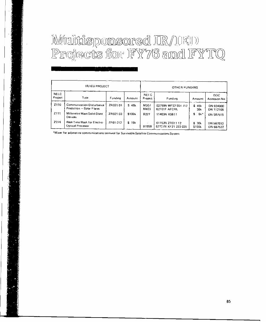
IR/IED PROJECT OTHER FUNDING
NELC NELC I DOCProject Title Funding Amount Project Funding Amount Accession No
Z110 Communication Disturbance ZR021 01 $ 48k M207 62759N WF52 551 717 $ 45k DN 034000Prediction - Solar Flares M403 62101F AFCRL 36k DN 112106
Zl1i MillimetreWaveSouid-State ZR021 03 $100k B227 11403N XSB11 $ 6k* DN 587515"Devices
Z274 Real-Time Mask for Electro- ZF61-212 $ 19k 61152N ZR011 12 $ 30k ON 587613. Optical Processor B195B 6272 IN XF21 222 025 $155k DN 687522
'Mixer for submarine communications terminal for Survivable Satellite Communications System
85
:1

Independent Research61152N, ZROOO 0101
NE LC Principal MatIl AUTOVON FY77' Research DOGProject Title Investigator Code 933- Funding Requirement Accession No
Z194 All Digital Signal Processing Dr I Lagnado 4800 6877 $ 84k ZR021 03 01 ON 487535
Functions Using CCDs
Z195 Solid-State Device Reliability Or CR Zeisse 4600 6591 175 ZR01 1 02 01 ON 487536and Vulnerability
Z102 Ill-V Semiconductor MIS Device Or DL Lile 4600 6591 169 ZR021 02 01 DN 587501Technology
Z104 High-Speed Electro-Optic Devices Dr HF Taylor 2500 7975 100 ZR011 12 01 ON 587503
Z105 Intercept and Identification RA Dillard 3300 2395 90 ZR021 05 01 ON 587504of Spread-Spectrum Signals
Z114 Advanced Concepts of the GL Haviland 4800 6877 85 ZR021 03 04 ON 687547CORDIC Algorithm
Z116 Molecular Vapor Dissociation Dr EJ Schimitschek 2500 7975 75 ZR01 1 07 01 ON 687585Laser
Z117 Blue-Green Propagation Through HG Hughes 2200 7703 149 ZR011 07 02 ON 687625Clouds
Z118 E lectrochromizs and Liquid P Soltan 2500 6641 50 ZR011 07 03 rON 687626Crystals
Z119 Lawrence Source Coding Dr DW Gage 3200 6515 6-" LZ014 0801 ON 687627
Z120 Capacitor Dielectric Breakdown NK Wagner 4600 6591 55 ZR022 06 01 ON 687628Investigation
Z121 Large Aperture Optical Modulator Or GC Mooradian 2500 7975 124 ZROI 1204 ON 781501
*IncludPs FYTQ carry over of $22k*To be terminater, 30 November 1976
I'86

',
Independent ExploratoryDevelopment62760N
NELC
NELC Principal Mail AUTOVON FY77 ED DDC
Project Title Investigator Code 933- Funding Task Area Accession No
Z287 Millimetre Wave Solid-State D Rubin 2300 2358 $ 90k ZF62 512 ON 587614
Devices (fornmer Z1 1)
Z288 Hf Radial Wire Ground Plane JM Horn 2100 2421 52 ZF61 212 DN 587613Analysis for Marine Corps
Z289 ECCM for Agile Radars BF Summers, Jr 2300 7407 90 ZF61 112 DN 587612
Z290 Infrared Image Enhancement by PS Catano 2500 7200 25 ZF61 112 ON 587612Video Processing
Z291 C2 Distributed Design and Dr RN Goss 5200 7431 133 ZF61 212 DN 587613Validation Process
Z292 An Adaptable Shipboard Tactical LCDR HC Schleicher 3300 6227 133 ZF61 212 DN 58,7613Data Distribution System _
87

EXTERNAL DISTRIBUTIONCopies Copies
Director of Navy Laboratories (MAT 03L) 3 Naval Ships Research and Development 1
Assistant Secretary of Navy for Research I Center, Annapolisand Development Naval Surface Weapons Center. White Oak 1
Director of Defense Research & Engineering 1 Naval Suface Weapons Center. Dahlgren 1(Research and Advanced Technology) Naval Undersea Center 1
Defense Advanced Research Projects Agency 1 Naval Underwater Systems Center, Newport 1(Dr GH Heilmeier) Naval Underwater Systems Center, New London 1
Chief of Naval Material (MAT 03) 3 Naval Weapons Center 1Chief of Naval Material (Dr Norris Keeler, MAT 03T) I Naval Postgraduate School 2Chief of Naval Material (MAT 0352) 1 US Naval Academy IChief of Nsval Operations (OP 98) 1 Office of Naval Research Branch Office Boston 1Chief of Naval Research (Code 401) 20 Office of Naval Research Branch Office Chicago iCommandant Marine Corps (MC-RD) 2 Office of Naval Research Branch Office Pasadena 2Naval Air Sys!ems Command (AIR 3022A) 4 Naval Research Advisory CommitteeNaval Electronics Systems Command (ELEX 301) 4 Laboratory Advisory Board for ResearchNaval Electronics Systems Command 1 Dr Victor C Anderson 1
(CAPT GH Smith. ELEX 09) Dr Bruno W Augenstein INaval Electronics Syste-ms Command 1 Dr William R Bennett. Jr 1
(CAPT JM McMorris, PME 117) Dr Eugene P Cronkite 1Naval Facilities Systems Command (FAC 03) 2 Dr Burton I Edelson 1Naval Sea Systems Command (SEA 03) 5 Prof Peter Franken 1Naval Medicar Researý.h & Development Command 1 VADM John T Hayward. USN (Ret) 1Marine Corps Development & Education Command 2 Or H Janet Healer 1Naval Air Development Center I Mr Brian T Howard 1Naval Coastal Systems Laboratory 1 Dr Harry D Huskey 1Naval Missile Center 1 Dr Augustus B Kinzel 1Naval Personnel Researct. & Development Center 1 Dr David Middleton 1Naval Research Laboratory 1 Dr David Z Robinson 1David W Taylor Naval Ships Research & 1
Development Center
88

INrl ASSIFIFDSECUF41 TY 4' C ASSI FICATION OF TH.IS PAGE (Who Ji., EJ.I.8n.,dJ
READ INSTRUCTIONSREPORT DOCUMENTATION PAGE BEFORE COMPL ETING FORM 5 J14' T MEI~t !. c OVT ACCESSION NO. 3 RECIPIENT'S CATALOG NUMBER
NI L(C rccliniicall Uocutiiciit.4l)f, (TD 496) i4 IIT~f arI.-II s TYPE OF REPORT A PERIOD COVERED
- A~ I*±j-A~4*f'~' -ANNUAL -- FY76 AND FYTQ
,ýfNDl INDEPNDNTJSARI EXLRTR DVLPE PERFORMING ORG. REPORT NUMBER
7- ArY<.ORI, 8 CONTRACT OR GRANT NUMBER(.)
'UR LI!-b-ss- ('nn~rdinjior
9 PERFORMING OGANGIZATION NAME AND ADDRESS Is PROGRAM IELEMENT.PROjECT, TASKARE A 6 WORK U NIT NUMBERS
Nival Electronics U-bOratory CenterSari[)ie'o. California 92152 -~?2~
IICC.N-;,,LFNG OFFICE NAME AND ADDRESS AI
Directuot I Navy Labolratolries 1101
14 MOPNT
ORIyI AGENCY NAME IADDRESS(II dlII*f-l 11-o Ca',rrIl-n OiIIt) IS SECURITY CLASS. (.[I)-,p
~ ~. J'JI 1jUnclassified- ---- IS. DIECLASSIFICATION,;OOWNGRAOINF
16 DIST RIBUT ION STATEMENT rol IhI R*PorIj
Approved tor public release: distribution is unilimiited
I7 DISTRIBUTION STATEMENT '01III abtc .nred i. BJook 20. It diffe-,4 hcoa' A&."oo)
IS SUPPLEMENTARY NOTES
19 KEY WORDS (CnOn*o.. .I. , it- de Int..1~911 by block ... bor)
liiocllgincering Independent research Wave propagationElectrociptics Integrated circuits SurveillanceIndependent explorato~ry development Signal processing USMCOptical comimunication Semiconductor devices Command and controlCharge-coupled devices Millimetire wave devires
20 ABSTRACT -Cadn, I--O* *Id. It. , "eewrad l~Id.f(I by biec ..h o
This document is an overview of the NELC IR and lED protrams. It Sunmmarizes the accomplishmentsachieved withinl each project in FY76 and I-YTQ. Longer articles are presented on three of the mostsignifticant projects -- (1) Optical Covert Communications Using Laser Transceivers (OCCULT), (2) TlIIVSemiconductor MIS Device Technology. and (3) Continuous Blood Pressure Monitoring.
DO , jAN73T 1473 EDITION OFl I NOV 65 IS OBSOLETE UCASFESIN 0102 LF 0ld 6601 UNCI-______________________
3ECURIYY CLASSIFICATION OF Y14IS PACE (DW- Di.46. EaImn