Embed Size (px)
Citation preview
Design Standard Instructions Topic No. 625-010-003
Index 450-010 Series Prestressed Florida-I Beams FY 2018-19
1
Index 450-010 Series Prestressed Florida-I Beams
Design Criteria
AASHTO LRFD Bridge Design Specifications; Structures Detailing Manual (SDM); Structures Design Guidelines (SDG)
Design Assumptions and Limitations
Index 450-010 is the lead standard for the Prestressed Florida-I Beam standard series which includes Indexes 450-010 through 450-096. Use this standard with Indexes 450-036, 450-045, 450-054, 450-063, 450-072, 450-078, 450-084, 450-096, 450-199, 400-510, and 450-511 or 450-512.
These Indexes must be supplemented with project specific information including a Table of Beam Variables, Strand Pattern Details and a Strand Debonding Legend which must be completed and included in the Structures Plans. These Indexes and the supplemental project specific information that is included in the plans provide sufficient information to permit beam fabrication without the submittal of shop drawings.
Data tables for associated Indexes 450-199, 400-510, and 450-511 or 450-512 must also be completed and included in the plans.
The use of End Diaphragms is not preferred on simple span, pretensioned, Florida-I Beam structures. In lieu of End Diaphragms, the preferred detail is a Thickened Slab End at all locations of slab discontinuity. Where End Diaphragms are required by design or for widening projects, partial depth diaphragms are preferred. See SDM Chapter 15 for suggested details.
Except for widening projects where special details may be required, squared beam ends are preferred on all Florida-I Beam structures.
The prestressed beams in these Standard Drawings are generally assumed to act as simple spans under both Dead Load and Live Load even where the deck is detailed to be continuous across the intermediate supports or back-to-back diaphragms are present. For detailing purposes, Prestressed Florida-I Beams are assumed to be erected plumb.
When the total initial tensioning force of the fully bonded strands required by design exceeds the values shown below, shield additional strands at the end of the beam when possible. The end reinforcement may only be redesigned to accommodate an increased vertical splitting force when approved by the State Structures Design Office. If approval is granted, Index 450-010 and the appropriate Standard Detail Drawings must then be modified for inclusion in the contract documents and signed and sealed by the EOR.
To limit vertical splitting forces in the webs of beams, the maximum prestress force at the beam ends from fully bonded strands must be limited to the following:
Design Standard Instructions Topic No. 625-010-003
Index 450-010 Series Prestressed Florida-I Beams FY 2018-19
2
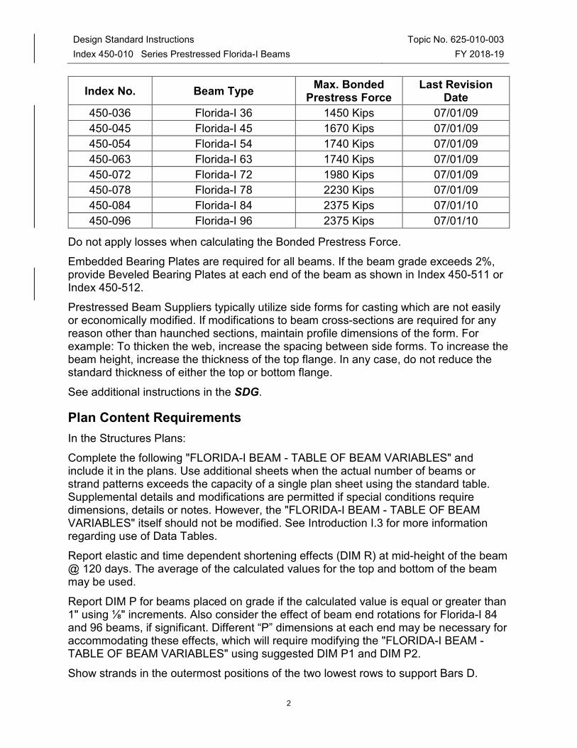
Index No. Beam Type Max. Bonded
Prestress Force Last Revision
Date
450-036 Florida-I 36 1450 Kips 07/01/09
450-045 Florida-I 45 1670 Kips 07/01/09
450-054 Florida-I 54 1740 Kips 07/01/09
450-063 Florida-I 63 1740 Kips 07/01/09
450-072 Florida-I 72 1980 Kips 07/01/09
450-078 Florida-I 78 2230 Kips 07/01/09
450-084 Florida-I 84 2375 Kips 07/01/10
450-096 Florida-I 96 2375 Kips 07/01/10
Do not apply losses when calculating the Bonded Prestress Force.
Embedded Bearing Plates are required for all beams. If the beam grade exceeds 2%, provide Beveled Bearing Plates at each end of the beam as shown in Index 450-511 or Index 450-512.
Prestressed Beam Suppliers typically utilize side forms for casting which are not easily or economically modified. If modifications to beam cross-sections are required for any reason other than haunched sections, maintain profile dimensions of the form. For example: To thicken the web, increase the spacing between side forms. To increase the beam height, increase the thickness of the top flange. In any case, do not reduce the standard thickness of either the top or bottom flange.
See additional instructions in the SDG.
Plan Content Requirements
In the Structures Plans:
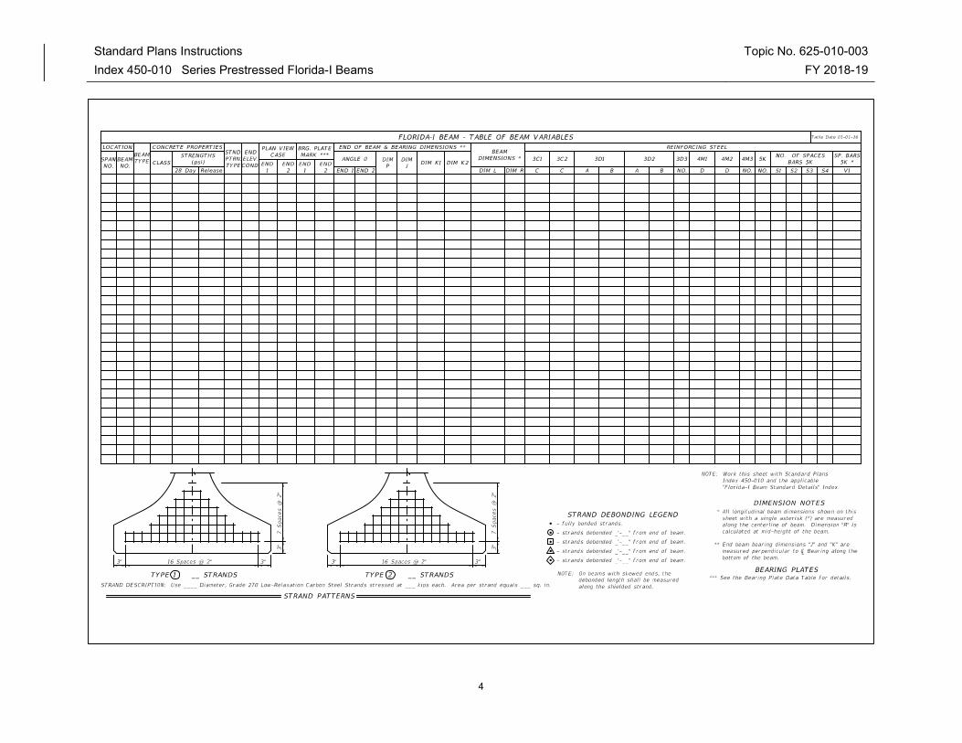
Complete the following "FLORIDA-I BEAM - TABLE OF BEAM VARIABLES" and include it in the plans. Use additional sheets when the actual number of beams or strand patterns exceeds the capacity of a single plan sheet using the standard table. Supplemental details and modifications are permitted if special conditions require dimensions, details or notes. However, the "FLORIDA-I BEAM - TABLE OF BEAM VARIABLES" itself should not be modified. See Introduction I.3 for more information regarding use of Data Tables.
Report elastic and time dependent shortening effects (DIM R) at mid-height of the beam @ 120 days. The average of the calculated values for the top and bottom of the beam may be used.
Report DIM P for beams placed on grade if the calculated value is equal or greater than 1" using ⅛" increments. Also consider the effect of beam end rotations for Florida-I 84 and 96 beams, if significant. Different “P” dimensions at each end may be necessary for accommodating these effects, which will require modifying the "FLORIDA-I BEAM - TABLE OF BEAM VARIABLES" using suggested DIM P1 and DIM P2.
Show strands in the outermost positions of the two lowest rows to support Bars D.
Design Standard Instructions Topic No. 625-010-003
Index 450-010 Series Prestressed Florida-I Beams FY 2018-19
3
Round Angle Φ up to the nearest degree.
Specify shear stirrup spacing V1 for Bars 5K to the nearest inch.
Prepare a Framing Plan for bridges meeting the criteria stated in the SDM.
When diaphragms are required by design, show them on the Framing Plan. Tabulate insert locations with respect to the beam ends and beam faces. Include length adjustments for beams placed on grade and for elastic and time dependent shortening effects. See SDM Chapter 15 for preferred diaphragm and reinforcing details.
For bridge widenings where beam ends are encased in full height diaphragms and the diaphragms are to be extended, modify Index 450-010 and the appropriate Index associated with the specific beam height and include them in the plans as follows:
• Modify the Standard Plans in accordance with Method 1, Method 2 or Method 3 as defined in the Terms Of Use for the Borderless DGNs provided in the Standard Plans eBooklet.
• Remove all notes, call-outs and details regarding cutting the strands and coating the ends of the beams with epoxy.
• Insert all notes, call-outs and details to ensure proper placement of Bars 4L as shown in the 2010 Design Standards Index 20010 Series Interims Dated 01/01/10 (Effective Date: July 1, 2010). Detail the number of bars, bar locations and bar bending diagrams.
Standard Plans Instructions Topic No. 625-010-003
Index 450-010 Series Prestressed Florida-I Beams FY 2018-19
4
Standard Plan Instructions Topic No. 625-010-003
Index 450-010 Series Prestressed Florida-I Beams FY 2018-19
5
Payment
Item number Item Description Unit Measure
450-2-AAA Prestressed Beams: Florida-I Beam LF
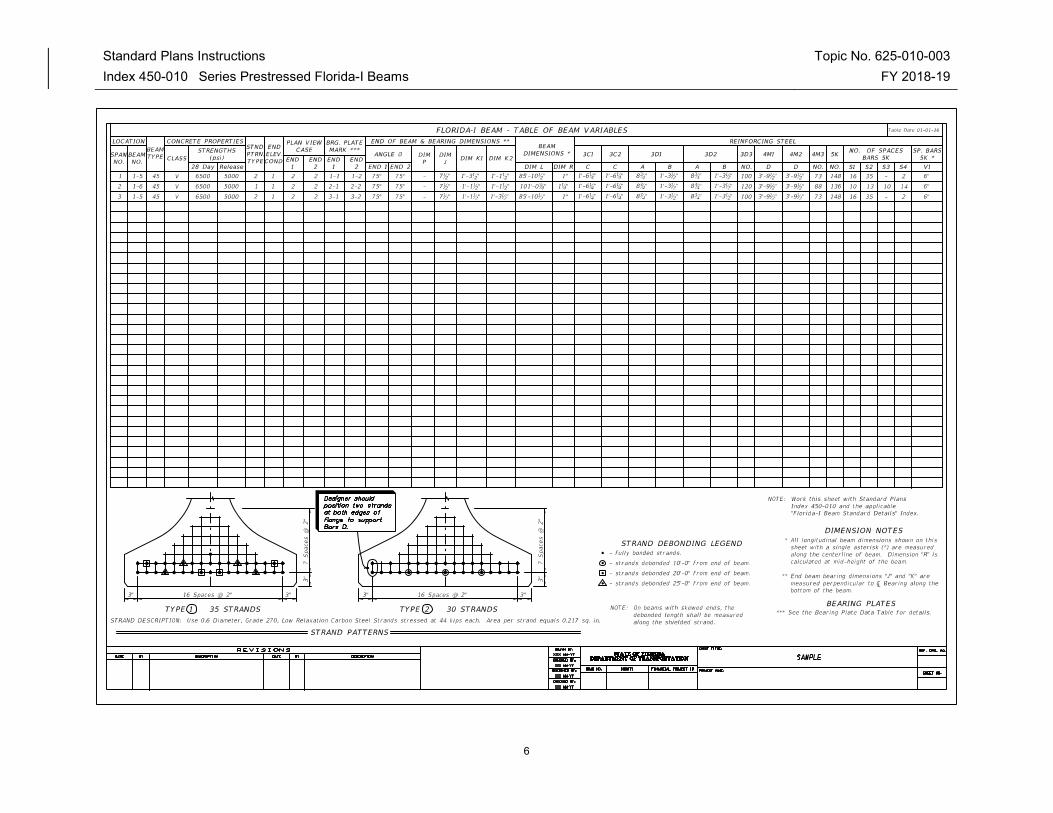
Example Problem
The following example shows the data required for completion of a Florida-I Beam Table of Beam Variables. The example assumes a three span bridge with Florida-I 45 Beams designed for the following conditions:
Live Load: HL-93
No intermediate Diaphragms
Stay-in-Place Metal Forms:
Allowance of 20 PSF non-composite dead load over the projected plan area of the forms (this includes the unit weight of metal forms and the concrete required to fill the form flutes).
Environment (Superstructure): Moderately Aggressive
Bridge Characteristics:
Length: 276 ft. Width: 51'-1" (out-to-out) Clear Roadway: 48 ft.
Superstructure:
Three simple spans of prestressed concrete beams with 8-inch composite deck slab (plus ½" sacrificial deck thickness)
Span: 87'-0", 102'-0", 87'-0"
Sidewalk: None
Horizontal Alignment: Straight
Vertical Alignment: 0.00% Grade
Skew Angle: 15 degrees (Right)
Beam Design:
Beam: Florida-I 45 Beam
Spacing:
11'-3", 87' Span (5 Beams) 9'-0", 102' Span (6 Beams)
Design Span Length:
84'-6" (Spans 1 & 3) 99'-8" (Span 2)
Standard Plans Instructions Topic No. 625-010-003
Index 450-010 Series Prestressed Florida-I Beams FY 2018-19
6
Standard Plans Instructions Topic No. 625-010-003
Index 450-010 Series Prestressed Florida-I Beams FY 2018-19
7
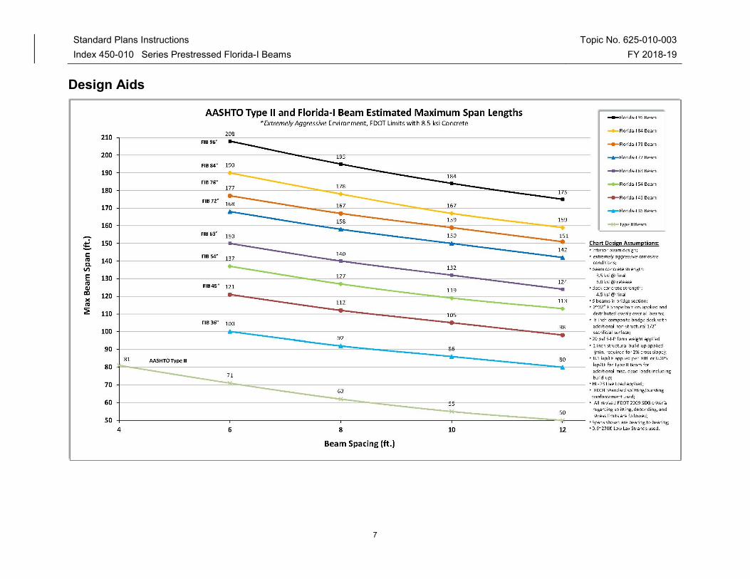
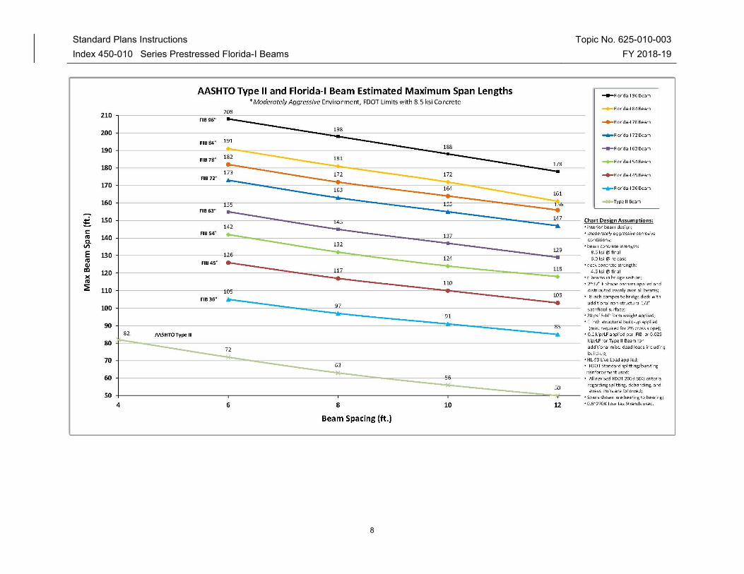
Design Aids
Standard Plans Instructions Topic No. 625-010-003
Index 450-010 Series Prestressed Florida-I Beams FY 2018-19
8
Standard Plans Instructions Topic No. 625-010-003
Index 450-010 Series Prestressed Florida-I Beams FY 2018-19
9
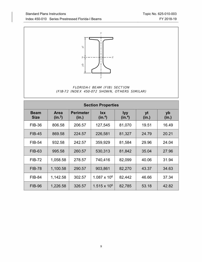
Section Properties
Beam Size
Area (in.2)
Perimeter (in.)
Ixx (in.4)
Iyy (in.4)
yt (in.)
yb (in.)
FIB-36 806.58 206.57 127,545 81,070 19.51 16.49
FIB-45 869.58 224.57 226,581 81,327 24.79 20.21
FIB-54 932.58 242.57 359,929 81,584 29.96 24.04
FIB-63 995.58 260.57 530,313 81,842 35.04 27.96
FIB-72 1,058.58 278.57 740,416 82,099 40.06 31.94
FIB-78 1,100.58 290.57 903,861 82,270 43.37 34.63
FIB-84 1,142.58 302.57 1.087 x 10⁶ 82,442 46.66 37.34
FIB-96 1,226.58 326.57 1.515 x 10⁶ 82,785 53.18 42.82