Embed Size (px)
Citation preview

1
Index S.
No.
Name of experiment Date of
performance
Experiment
marks
Teacher‟s
Signature
1. To determine the coefficient of impact for
vanes.
2 To determine coefficient of discharge of an
orificemeter.
3 To determine the coefficient of discharge of
Notch (V and Rectangular types)
4 To determine the friction factor for the
pipes.
5 To determine the coefficient of discharge of
venturimeter.
6 To determine the coefficient of discharge,
contraction & velocity of an orifice.
7 To verify the Bernoulli‟s Theorem.
8 To find critical Reynolds number for a
pipe flow.
9 To determine the meta-centric height of a
floating body.
10 To determine the minor losses due to
sudden enlargement, sudden contraction
and bends.
11 To show the velocity and pressure
variation with radius in a forced vortex
flow.

2
EXPERIMENT NO. 1
Aim: - To determine the co efficient of impact for vanes.
Apparatus Used:- Collecting tank, Transparent cylinder, Two nozzles of dia 10 mm &
12mm, Vane of different shape (flat, inclined or curved)
Theory:- Momentum equation is based on Newton‟s second law of motion which states that
the algebraic sum of external forces applied to control volume of fluid in any direction is equal to
the rate of change of momentum in that direction. The external forces include the component of
the weight of the fluid & of the forces exerted externally upon the boundary surface of the
control volume. If a vertical water jet moving with velocity is made to strike a target, which is
free to move in the vertical direction then a force will be exerted on the target by the impact of
jet, according to momentum equation this force (which is also equal to the force required to bring
back the target in its original position) must be equal to the rate of change of momentum of the
jet flow in that direction.
Figure: Impact of jet
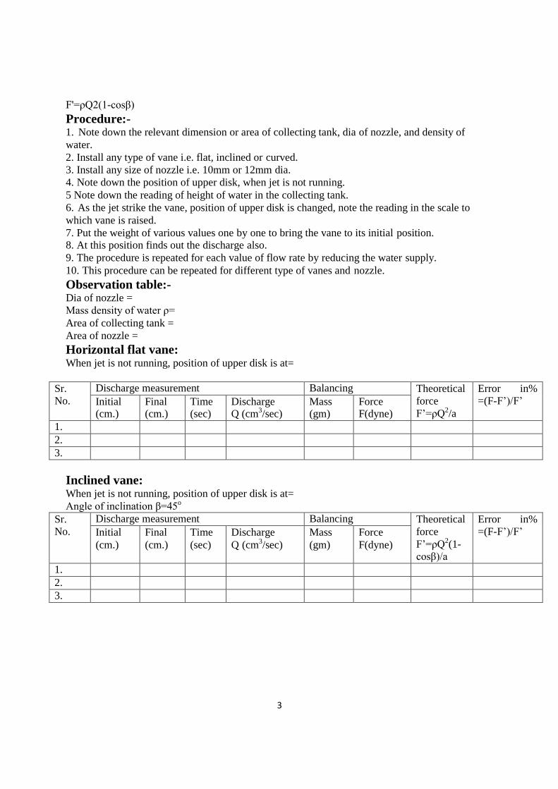
Formula Used:- F'=ρQ v(1-cosβ)
F'=ρQ2(1-cosβ) as v=Q/a
Where F' =force (calculated)
ρ= density of water
β=angle of difference vane
V =velocity of jet angle
Q =discharge
A =area of nozzle ( π/4d2)
(i) for flat vane β=90
F = ρQ2/a
(ii) for hemispherical vane β=180o
for % error =F- F'/F'x100
F = 2 ρQ2/a
F = Force (due to putting of weight)
(iii) for inclined vane
F'=ρQ v(1-cosβ)
3
F'=ρQ2(1-cosβ)
Procedure:- 1. Note down the relevant dimension or area of collecting tank, dia of nozzle, and density of
water.
2. Install any type of vane i.e. flat, inclined or curved.
3. Install any size of nozzle i.e. 10mm or 12mm dia.
4. Note down the position of upper disk, when jet is not running.
5 Note down the reading of height of water in the collecting tank.
6. As the jet strike the vane, position of upper disk is changed, note the reading in the scale to
which vane is raised.
7. Put the weight of various values one by one to bring the vane to its initial position. 8. At this position finds out the discharge also.
9. The procedure is repeated for each value of flow rate by reducing the water supply.
10. This procedure can be repeated for different type of vanes and nozzle.
Observation table:- Dia of nozzle =
Mass density of water ρ=
Area of collecting tank =
Area of nozzle =
Horizontal flat vane: When jet is not running, position of upper disk is at=
Sr.
No.
Discharge measurement Balancing Theoretical
force
F‟=ρQ2/a
Error in%
=(F-F‟)/F‟ Initial (cm.)
Final (cm.)
Time (sec)
Discharge Q (cm3/sec)
Mass (gm)
Force F(dyne)
1.
2.
3.
Inclined vane: When jet is not running, position of upper disk is at=
Angle of inclination β=45o
Sr.
No.
Discharge measurement Balancing Theoretical
force
F‟=ρQ2(1- cosβ)/a
Error in%
=(F-F‟)/F‟ Initial
(cm.)
Final
(cm.)
Time
(sec)
Discharge
Q (cm3/sec)
Mass
(gm)
Force
F(dyne)
1.
2.
3.

4
Curved hemispherical vane: When jet is not running, position of upper disk is at=
Sr. No.
Discharge measurement Balancing Theoretical
force
F‟=2ρQ2/a
Error in% =(F-F‟)/F‟ Initial
(cm.) Final (cm.)
Time (sec)
Discharge Q (cm3/sec)
Mass (gm)
Force F(dyne)
1.
2.
3.
Precautions:- 1. Water flow should be steady and uniform.
2. The reading on the scale should be taken without any error.
3. The weight should be put slowly & one by one.
4. After changing the vane the flask should be closed tightly.
Viva Questions:- 1. Define the terms impact of jet and jet propulsion? 2. Find the expression for efficiency of a series of moving curved vane when a jet of water
strikes the vanes at one of its tips?

5
Experiment No. 2
Aim:- To determine the coefficient of discharge of Orifice meter.
Apparatus Used:- Orifice meter, installed on different pipes, arrangement of varying flow
rate, U- tube manometer, collecting tube tank, vernier calliper tube etc.
Formula Used: - Cd
= Q.ƒÆ2–a2
Æ.a.ƒ2g∆h
Where
A = Cross section area of inlet
a = Cross section area of outlet
Δh = Head difference in manometer
Q = Discharge
Cd = Coefficient of discharge
g = Acceleration due to gravity
Theory:- Orifice meter are depending on Bernoulli‟s equation. Orificemeter is a device used
for measuring the rate of fluid flowing through a pipe. It is a cheaper device than Venturimeter.
Figure: Orificemeter
Procedure:- 1. Set the manometer pressure to the atmospheric pressure by opening the upper valve.
2. Now start the supply at water controlled by the stop valve.
3. One of the valves of any one of the pipe open and close all other of three.
4. Take the discharge reading for the particular flow.
5. Take the reading for the pressure head on from the u-tube manometer for corresponding
reading of discharge.
6. Now take three readings for this pipe and calculate the Cd for that instrument using formula.
7. Now close the valve and open valve of other diameter pipe and take the three reading for this.
8. Similarly take the reading for all other diameter pipe and calculate Cd for each.
Observations:- Diameter of Orifice meter =
Area of cross section =
Area of collecting tank =

6
Discharge Manometer reading Cd
Q. √A2 − a2 =
A. a. ƒ2g∆ℎ
Initial
(cm.)
Final
(cm)
Difference Time
(sec)
Discharge H1 H2 H2-
H1
Δh=13.6(H2-
H1)
Result:-
Precautions:- 1. Keep the other valve closed whiletaking reading through one pipe.
2. The initial error in the manometer should be subtracted final reading.
3. The parallax error should be avoided.
4. Maintain a constant discharge for each reading.
5. The parallax error should be avoided while taking reading the manometer.
Viva Questions:- 1. Orificemeter are used for flow measuring. How?
2. Difference between Orificemeter and Venturimeter?

7
J
2 (
Experiment No. 3
Aim: - To determine the coefficient of discharge of Notch (V, Rectangular and Trapezoidal
types).
Apparatus Used:- Arrangement for finding the coefficient of discharge inclusive of supply
tank, collecting tank, pointer, scale & different type of notches
Theory:- Notches are overflow structure where length of crest along the flow of water is
accurately shaped to calculate discharge.
Formula Used:- For V notch the discharge coefficient Q
Cd =
For Rectangular notch
8 J2gH5
tan 8
) 15 2
Q Cd =
For Trapezoidal notch
2 3
3 2gBH2
Q Cd =
2 J 8 3
Where:-
Q = Discharge
H =Height above crest level
θ= Angle of notch
B = Width of notch
3 2g(B + tan 2) H2
Figure: Notches
Procedure:- 1. The notch under test is positioned at the end of tank with vertical sharp edge on the upstream
side.
2. Open the inlet valve and fill water until the crest of notch.
3. Note down the height of crest level by pointer gauge.
4. Change the inlet supply and note the height of this level in the tank.

8
5. Note the volume of water collected in collecting tank for a particular time and find out the
discharge.
6. Height and discharge readings for different flow rate are noted.
Observations:- Breath of tank =
Length of tank =
Height of water to crest level for rectangular notch is =
Height of water to crest level for V notch =
Height of water to crest level for Trapezoidal notch =
Angle of V notch =
Width of Rectangular notch =
Type of
Notch
Discharge Final
height
reading
above width
Head
above
crest
level
Cd
Initial
height
in tank
Final
height
in tank
Difference
in height
Volume Q
Precaution:- 1. Make the water level surface still, before takings the reading.
2. Reading noted should be free from parallax error.
3. The time of discharge is noted carefully.
4. Only the internal dimensions of collecting tank should be taken for consideration and
calculations.
Result: The value of Cd for V-notch……
The value of Cd for rectangular notch……
The value of Cd for trapezoidal notch ……
Viva Questions:- 1. Differentiate between :- • Uniform and non uniform flow
• Steady and unsteady flow
2. Define notch?
3. What is coefficient of discharge?

9
f
f
EXPERIMENT NO. 4
Aim:- To determine the friction factor for the pipes.(Major Losses).
Apparatus Used:- A flow circuit of G. I. pipes of different diameter viz. 15 mm, 25mm, 32
mm dia, U-tube differential manometer, collecting tank.
Theory:-
Figure: Losses in pipes during flow
Friction factor in pipes or Major losses:- A pipe is a closed conduit through which fluid flows
under the pressure. When in the pipe, fluid flows, some of potential energy is lost to overcome
hydraulic resistance which is classified as:-
1. The viscous friction effect associated with fluid flow.
2. The local resistance which result from flow disturbances caused by
Sudden expansion and contraction in pipe
Obstruction in the form of valves, elbows and other pipe fittings.
Curves and bend in the pipe.
Entrance and exit losses.
The viscous friction loss or major loss in head potential energy due to friction is given by
h = 4 fSv2
2gd Hence the major head loss is friction loss
Where,
hf =Major head loss
l = Length of pipe
4f = Friction factor
v = Inlet velocity
h = 4 fSv2
2gd -------- Darcy equation
g = Acceleration due to gravity
d = Diameter of pipe

10
Procedure:- 1. Note down the relevant dimensions as diameter and length of pipe between the pressure
tapping, area of collecting tank etc.
2. Pressure tapping of a pipe is kept open while for other pipe is closed.
3. The flow rate was adjusted to its maximum value. By maintaining suitable amount of steady
flow in the pipe.
4. The discharge flowing in the circuit is recorded together with the water level in the left and
right limbs of manometer tube.
5. The flow rate is reduced in stages by means of flow control valve and the discharge & reading
of manometer are recorded.
6. This procedure is repeated by closing the pressure tapping of this pipe, together with other
pipes and for opening of another pipe.
Observation:- Diameter of pipe D =
Length of pipe between pressure tapping L =
Area of collecting tank =
Sr. No.
Manometer Reading Discharge measurement F = n2gD5 /8LQ2ℎf Left
limb
H1
Right
limb
H2
Difference
of head in
terms of
water hf =
13.6 (H2- H1)
Initial
cm.
Final
cm.
Time
sec
Discharge
Q
(cm3/sec)
Precautions:- 1. When fluid is flowing, there is a fluctuation in the height of piezometer tubes, note the mean
position carefully.
2. There in some water in collecting tank.
3. Carefully keep some level of fluid in inlet and outlet supply tank.
Result:-
Viva Questions:- 1. Define major loss in pipe?
2. Define equilent pipe?
3. Define friction factor in the pipe?

11
EXPERIMENT NO. 5
Aim:- To determine the coefficient of discharge of Venturimeter.
Apparatus Used:- Venturimeter, installed on different diameter pipes, arrangement of
varying flow rate, U- tube manometer, collecting tube tank, vernier calliper tube etc.
Formula Used:- Q. √A2 — a2
Cd = A. a. ƒ2g∆h
Where
A = Cross section area of inlet
a = Cross section area of outlet
Δh = Head difference in manometer
Q = Discharge
Cd= Coefficient of discharge
g = Acceleration due to gravity
Theory:- Venturimeter are depending on Bernoulli‟s equation. Venturimeter is a device used for measuring the rate of fluid flowing through a pipe. The consist of three part in short
1. Converging area part
2. Throat
3. Diverging part
Figure: Venturimeter
Procedure:- 1. Set the manometer pressure to the atmospheric pressure by opening the upper valve. 2. Now start the supply at water controlled by the stop valve.
3. One of the valves of any one of the pipe open and close all other of three.
4. Take the discharge reading for the particular flow.
5. Take the reading for the pressure head on from the u-tube manometer for corresponding
reading of discharge.
6. Now take three readings for this pipe and calculate the Cd for that instrument using formula.
7. Now close the valve and open valve of other diameter pipe and take the three reading for this.
8. Similarly take the reading for all other diameter pipe and calculate Cd for each.

12
Observations:- Diameter of Venturimeter=
Area of cross section =
Venturimeter=
Area of collecting tank=
Discharge Manometer reading Cd
Q. √A2 − a2 =
A. a. ƒ2g∆ℎ
Initial
(cm.)
Final
(cm)
Difference Time
(sec)
Discharge H1 H2 H2-
H1
Δh=13.6(H2-
H1)
Result:-
Precautions:- 1.Keep the other valve closed while taking reading through one pipe.
2.The initial error in the manometer should be subtracted final reading.
3.The parallax error should be avoided.
4. Maintain a constant discharge for each reading. 5. The parallax error should be avoided while taking reading the manometer.
Viva Questions:- 1. Venturimeter are used for flow measuring. How? 2. Define co efficient of discharge?
3. Define parallax error?
4. Define converging area part?
5. Define throat?
6. Define diverging part?

13
EXPERIMENT NO. 6
Aim:- To determine the coefficient of discharge, contraction & velocity of an Orifice.
Apparatus Used:- Supply tank with overflow arrangement, Orifice plate of different
diameter, hook gauge, collecting tank, piezometric tube.
Formula Used:-
C = QactuaS
d QtheoreticaS
Qtheoretical = Theoretical velocity x Theoretical area = ƒ2gh . a Q
Cd = ƒ2gh . a
Cv = actual velocity of jet at vena contracta
theoretical velocity
coefficient of contraction = area of jet at vena contracta
area of orifice ac
Cc = a
Figure: Flow through Orifice Theory:- A mouthpiece is a short length of pipe which is two or three times its diameter in
length. If there pipe is filled externally to the orifices, the mouthpiece is called external
cylindrical mouthpiece and discharge through orifice increase is a small opening of any cross-
section on the side of bottom of the tank, through which the fluid is flowing orifice coefficient of
velocity is defined as the ratio of two actual
discharge to orifice ratio of the actual velocity of the jet at vena- contracta to the coefficient of
theoretical velocity of the jet coefficient of contraction of defined as ratio of the actual velocity
of jet at vena- contracta.

14
Vena- Contracta:- The fluid out is in form of jet goes on contracting form orifice up todispute of
about ½ the orifice dia. After the expend this least relation.
Coefficient of velocity:- It is a ratio of actual velocity jet at vena-contracta to theoretical velocity.
Coefficient of contraction:-
C = ac
c a
coefficient of contraction =
Coefficient of discharge:-
area of jet at vena contracta
area of orifice
Procedure:-
C = QactuaS
d QtheoreticaS
1. Set the mouthpiece of orifice of which the Cc, Cu, Cd are to be determined.
2. Note the initial height of water in the steady flow tank and the height of datum from the
bottom of orifice and mouthpiece. These remains constant for a particular mouthpiece or orifice.
3. By using the stop valve, set a particular flow in tank and tank height of water in tank.
4. Take the reading of discharge on this particular flow.
5. Using hook gauge, find the volume of Xo Y for mouthpiece.
6. Take three readings using hook gauge for one particular orifice.
7. Using the formula get value of Cd, Cu, and Cc for a particular orifice and mouthpiece.
Observation:- x' + y' are reading on horizontal/vertical scale
ao h=µao x‟ y‟ X=x‟-xoy Y=y‟-yo Cu=x/2gh Average
h = Reading on piezometer
a0 = Reading on piezometer at level on centre of mouthpiece
y0 = Reading on vertical scale at exit of orifice
x0 = Reading on horizontal scale at exit of orifice
Sr. No. X ZP FR volume time Q=V Cd=Q/2gh Average
Precautions:- 1. Take the reading of discharge accurately.
2. Take value of h without any parallax error.
3. Set the orifice and mouthpiece.
4. Height of water in the steady flow.
5. Take reading from hook gauge carefully.
Result:-

15
Viva Questions:- 1. Define Orifice?
2. Define Mouth piece?
3. Define vena contracta?
4. Define co efficient of velocity?

16
1
2
EXPERIMENT NO. 7
Aim:- To verify the Bernoulli‟s theorem.
Apparatus Used:- A supply tank of water, a tapered inclined pipe fitted with no. of
piezometer tubes point, measuring tank, scale, stop watch.
Theory:- Bernoulli‟s theorem states that when there is a continues connection between the
particle of flowing mass liquid, the total energy of any sector of flow will remain same provided
there is no reduction or addition at any point.
Formula Used:-
H1 = Z1 + P1⁄w + V2⁄2g
H2 = Z2 + P2⁄w + V2⁄2g
Procedure:- 1. Open the inlet valve slowly and allow the water to flow from the supply tank.
2. Now adjust the flow to get a constant head in the supply tank to make flow in and out flow
equal.
3. Under this condition the pressure head will become constant in the piezometer tubes.
4. Note down the quantity of water collected in the measuring tank for a given interval of time.
5. Compute the area of cross-section under the piezometer tube.
6. Compute the area of cross-section under the tube.
7. Change the inlet and outlet supply and note the reading.
8. Take at least three readings as described in the above steps.
Observation table: 1 2 3 4 5 6 7 8 9 10 11
Reading of piezometric tubes
Area of cross
section under the
foot of each point
Velocity of water
under foot of each
point
V2/2g
p/ρ
V2/2g + p/ρ
Precautions:- 1. When fluid is flowing, there is a fluctuation in the height of piezometer tubes, note the mean
position carefully.
2. Carefully keep some level of fluid in inlet and outlet supply tank.
Result:-
Viva Questions:- 1. Briefly explain the various terms involved in Bernoulli‟s equation?
2. Assumption made to get Bernoulli‟s equation from Euler‟s equation by made?

17
3. What is piezometer tube?

18
EXPERIMENT NO. 8
Aim:- To find critical Reynolds number for a pipe flow.
Apparatus Used:- Flow condition inlet supply, elliptical belt type arrangement for coloured
fluid with regulating valve, collecting tank.
Formula Used:- Reynolds No = Inertia force/Viscous force
Theory:-
Figure: Reynold No. apparatus
Reynolds Number:- It is defined as ratio of inertia force of a flowing fluid and the viscous force
of the fluid. The expression for
Reynolds number is obtained as:-
Inertia force (Fi) = mass . acceleration of flowing
= δ. Volume. Velocity/ time
= δ. voSuNeVelocity tiNe
= δ.area .Velocity . Velocity
= δ.A .V2
Viscous force (Fv) = Shear stress . area
= τ. A
= μ. du/dy . A
= VA/τ
By definition Reynolds number:-
Re= Fi/Fu
= δAV2/μ/t.A
= V.L /μ/s
= V.L /v { v = μ/ ρis kinematics viscosity of the fluid }
In case of pipe flow, the linear
dimension L is taken as dia (d) hence
Reynolds number for pipe flow is :-

19
Re = V .d /v or
Re = ρVd /v
Procedure:- 1. Fill the supply tank some times before the experiment. 2. The calculated fluid is filled as container.
3. Now set the discharge by using the valve of that particular flow can be obtained.
4. The type of flow of rate is glass tube is made to be known by opening the valve of dye
container.
5. Take the reading of discharge for particular flow.
6. Using the formula set the Reynolds no. for that particular flow, aspect the above procedure for
all remaining flow.
Observation:- Type Time Discharge Q=m3/3 Re=4Q/πΔV
initial Final Difference Volume
Precaution:- 1. Take reading of discharge accurately.
2. Set the discharge value accurately for each flow.
Result:-
Viva Questions:- 1. Reynolds number importance?
2. Describe the Reynolds number experiments to demonstrate the two type of flow?
3. Define laminar flow, transition flow and turbulent flow?

20
EXPERIMENT NO. 9
Aim:- To determine the Meta-centric height of a floating body.
Apparatus Used:- Take tank 2/3 full of water, floating vessel or pontoon fitted with a
pointed pointer moving on a graduated scale, with weights adjusted on a horizontal beam.
Theory: -
Figure: Metacentric Height apparatus Consider a floating body which is partially immersed in the liquid, when such a body is tilted,
the center of buoyancy shifts from its original position „B‟ to „B‟ (The point of application of
buoyanant force or upward force is known as center of G which may be below or above the
center of buoyancy remain same and couple acts on the body. Due to
this couple the body remains stable. At rest both the points G and B also Fb x Wc act through
the same vertical line but in opposite direction. For
small change (θ) B shifted to B.
The point of intersection M of original vertical line through B and G with the new vertical, line
passing through „B‟ is known as metacentre. The distance between G and M is known as
metacentre height which is measure of static stability.
Formula Used:- WN. Xd GM =
(W + W ) tan 8 c N
Where: - Wm is unbalanced mass or weight.
Wc is weight of pontoon or anybody.
Xd is the distance from the center of pointer to striper or unbalanced weight.
θ is angle of tilt or heel.
Procedure: - 1. Note down the dimensions of the collecting tank, mass density of water.
2. Note down the water level when pontoon is outside the tank.
3. Note down the water level when pontoon is inside the tank and their difference.
4. Fix the strips at equal distance from the center.
5. Put the weight on one of the hanger which gives the unbalanced mass.
6. Take the reading of the distance from center and angle made by pointer on arc.
7. The procedure can be repeated for other positioned and values of unbalanced mass.

21
Observation Table:- Length of the tank =
Width of the tank =
Area of the tank =
Initial level of the water without pontoon X1 =
Final level of the water with pontoon X2 =
Difference in height of water (X) = X2–X1=
Height of water in
tank with
pontoon X2
Difference
in height
X=X2-X1
Weight of
pontoon
Wc=XAρ
Unbalanced
mass Wm
Kg
Q GM=Metacentric
Height (m)
Xd (m)
Precautions: - 1. The reading taking carefully without parallax error.
2. Put the weight on the hanger one by one.
3. Wait for pontoon to be stable before taking readings.
4. Strips should be placed at equal distance from the centre.
Result:- Meta centric height of the pontoon is measured with different positions and weights
and value is………….
Viva Questions:- 1. Define Buoyancy?
2. Define Meta-centre?
3. Define Meta- centric height?
4. With respect to the position of metacentre, state the condition of equilibrium for a floating
body?

22
EXPERIMENT NO. 10
Aim:- To determine the minor losses due to sudden enlargement, sudden contraction and bend.
Apparatus Used:- A flow circuit of G. I. pipes of different pipe fittings viz. Large bend,
Small bend, Elbow, Sudden enlargement from 25 mm dia to 50 mm dia, Sudden contraction
from 50 mm dia to 25 mm dia, U-tube differential manometer, collecting tank.
Theory:- Minor Losses:-
Figure: Loss due to sudden enlargement Figure: Loss due to bend
Figure: Loss due to sudden contraction
The local or minor head losses are caused by certain local features or disturbances. The
disturbances may be caused in the size or shape of the pipe. This deformation affects the velocity
distribution and may result in eddy formation.
Sudden Enlargement:- Two pipe of cross-sectional area A1 and A2 flanged together with a
constant velocity fluid flowing from smaller diameter pipe. This flow breaks away from edges of
narrow edges section, eddies from and resulting turbulence cause dissipation of energy. The
initiations and onset of disturbances in turbulence is due to fluid momentum and its area.
It is given by:- h exit =V2/2g
Eddy loss:- Because the expansion loss is expended exclusively on eddy formation and
continues substance of rotational motion of fluid masses.
Sudden Contraction:- It represents a pipe line in which abrupt contraction occurs.
Inspection of the flow pattern reveals that it exists in two phases.
hcon = (Vc – V2)2/2g
Where
Vc = velocity at vena contracta

23
Losses at bends, elbows and other fittings:-
The flow pattern regarding separation and eddying in region of separations in bends, valves. The
resulting head loss due to energy dissipation can be prescribed by the relation h = KV2/2g.
Where V is the average flow velocity and the resistance coefficient K dependson parameter
defining the geometry of the section and flow. Resistances of large sizes elbows can be reduced
appreciably by splitting the flow into a number of streams by a jet of guide vanes called
cascades.
Procedure:- 1. Note down the relevant dimensions as diameter and length of pipe between the pressure
tapping, area of collecting tank etc.
2. Pressure tapping of a pipe a is kept open while for other pipe is closed. 3. The flow rate was adjusted to its maximum value. By maintaining suitable amount of steady
flow in the pipe.
4. The discharge flowing in the circuit is recorded together with the water level in the left and
right limbs of manometer tube.
5. The flow rate is reduced in stages by means of flow control valve and the discharge & reading
of manometer are recorded.
6. This procedure is repeated by closing the pressure tapping of this pipe, together with other
pipes and for opening of another pipe.
Observation:- Diameter of pipe D =
Length of pipe between pressure tapping L =
Area of collecting tank =
Types of the fitting =
Sr.
No.
Manometer reading Discharge measurement Coefficient
of loss K=
2g/V2.hL
Left limb
h1
Right
limb h2
Difference of
head in terms of
water hf = 13.6 (h2-h1)
Initial final time Discharge
1
2
3
Precautions:- 1. When fluid is flowing, there is a fluctuation in the height of piezometer tubes, note the mean
position carefully.
2. There in some water in collecting tank.
3. Carefully keep some level of fluid in inlet and outlet supply tank.
Result:-
Viva Questions:- 1. Define hydraulic gradient and total energy lines?
2. Define eddy loss?

24
3. Define sudden contraction?
4. Define sudden enlargement?

25
EXPERIMENT NO. 11
Aim:- To study Viscosity, Velocity & Pressure measuring device.
Theory:- Viscosity measuring device:-
1. Capillary tube
2. Viscometer.
Capillary tube:- Poiseiulle showed that the volume (v) of a liquid or gas flowing per second
through a horizontal capillary tube of a given radius length (L) under a constant difference of
pressure (ΔP) between two ends is inversely proportional to the viscosity of fluid. The volume of
fluid through the f tube in t is given by
The lesser the volume of flowing fluid through the tube per unit time, the larger the viscosity.
Viscometer:- It is an instrument to measure the viscosity. It measures some quantity which is a
function of viscosity. The quantity measured is usually time taken to pass certain volume of the
liquid through an orifice fluid at the bottom of the viscometer. The temperature of liquid, while it
is being passed through the orifice should be maintained constant. Some viscometer is used are
say bolt universally, redwood, Engler viscometer which has a vertical tube. The times in second
to pass 60cc of fluid liquid for the determination of viscosity is “say bolt second”.
The following empirical relations are used to determine kinematics viscosity in stokes:-
A) Say bolt universal viscometer
B) Red wood viscometer
C) Engler viscometer
Velocity measuring device:- Rota Meter.
Construction:- A Rota meter is a device to find the velocity of a flow in a pipe with the aid of
rotating free float. It is essentially an orifice meter with fixed pressure drop and variable orifice
area. Fluid is allowed to flow vertically upward through a tapered transparent tube placed
vertically with a large end at the top. The float is freely suspended upside the tube. The
maximum diameter of float is slightly less then the minimum bore. There are two L-bend lies on
the inlet and outlet of the tube. Guide wire for float is calibrated at the centre of the tapered tube.
The outlet portion for fluid generally less then the inlet portion. The tapered tube is generally
having the glass covering on the part of taking the reading of the float
Working:- When there is no flow, float rests at bottom, but fluid when some velocity float has
rises upward to make way for fluid motion. The float rises to such a position that the pressure
loss across the amuler orifice just balances to the weight of the float mechanism which is
attached to it. The float therefore attains a state of equilibrium and the distance from the stop to
float is a measure of the discharge in liter/second. The float is provided with slantwise slots to
enable it to occupy a stable position at the center of tube.
Pressure measuring device:-
A) Dead weight piston gauge
B) Mechanical gauge
A) Dead weight piston gauge:- This is the direct method for precise determination to of a piston
steady pressure measurement. The instrument consists of a piston & a cylinder of known area
connected to a fluid pressure on the piston equal to the pressure times the piston area. This force
can be balanced by weight fitted on the top of the vertical piston. This is the most accurate
device and used for precision and for calibrating other pressure gauge. The pressure of liquid is
balanced by known weight. Pressure in Kgf/cm2 or KN/m2
B) Mechanical gauge:- By the help of spring or dead weight balanced the liquid column whose
pressure is to be measured. In gauge are the liquid exert the force on

26
a movable diaphragm
or piston, which is the
resisted by a spring of
known valve. The
intensity of pressure
then would be equal
to the force F divided
by the area
a of the diaphragm or piston P =F/a They are suited for
the measurement of
high pressure when it
is more then to
atmospheres. The
most accurate and
reliable region on the
scale of mechanical
gauge in between
40% & 70% of the
maximum may give
direct pressure
reading, portability
and wider operating
gauge. They can fairly
accurate reading if
properly calibrated.
1
B
o
u
r
d
o
n
t
u
b
e
p
r
e
s
s
u
re
gauge
2
Diaphr
agm
pressur
e
gauge
3 Dead weight pressure gauge
Viva Questions:- 1 Define and explain the Newton‟s law of viscosity?
2 Define construction of
bourdon tube pressure gauge?
3 Define construction of
Rotameter?
4 What is meant by calibration?
5 Which type of fluid is used in bourdon tube pressure gauge?
FRICTION IN PIPES

27
Re 4
1
Aim: To determine the Co-efficient of friction in flow through pipes of various sizes.
Theory:
When a fluid is flowing through a pipe, the fluid experiences some resistance due to which
some of the energy of fluid is lost. The loss of energy is classified into
1. Major energy loss: this is due to friction and it is calculated by the following
formulae:
a) Darcy-Weisbach Formula hf 4fLV
2
2gd
Where, hf = loss of head due to friction f = co-efficient of friction which is a function of
Reynolds number.
= 16
Re
for Re 2000
= 0.079
for R
var ying from 4000 to 106
b) Chezy‟s formula
L = length of pipe
V = mean velocity of flow d
= diameter of pipe.
Where, C = Chezy‟s Constant
m for pipe is always equal to d 4
i = loss of head due to friction/unit length of pipe.
Procedure:
1. Switch on the pump and open the delivery valve.
2. Open the corresponding ball valve of pipe under consideration.
3. Keep the ball valve of other pipeline closed.
4. Note down the differential head readings in the manometer. (Expel if any air is present
by opening the drain cocks provided to the manometer).
5. Close the butterfly valve and note down the time taken for known water level rise.
where hf is loss of head.
e

28
hf = H
SHg
S
1m of water.
w
H = Manometer reading in m of Hg
6. Change the flow rate and take the corresponding reading
7. Repeat the experiment for different diameter of pipelines.
Table of calculations:
Type
Difference in
Mercury level
Rise of
water
in m
Time
taken
in sec
Discharge
Q
(m3/s)
Velocity
V
(m/s)
Loss
of
head
in m
Co-efficient
of Friction
h 1
h 2
H=
h1-h2
in m

29
Work Sheet
Date: Signature of Faculty

30
SUDDENCONTRACTION
SHORTBEND
SUDDENEXPANSION
LONGBEND
BUTTERFLYVALVE TUBES
WATERLEVELINDICATOR
MANOMETER
BALLVALVE
COONTROLVALVE
SUMP
PUMP
Observations.
Area of Tank, A = 0.125 m2
EXPERIMENTALSETUP
Formulae:
Discharge Q =
AR m3
t s
Where, R = Rise in water level in collecting tank. (In m) t
= time in seconds.
Velocity of flow, V = Q
m / s a
d 2 2
Cross sectional area of pipe a =
Loss of energy due to sudden expansion.
m where„d‟ is inner diameter of pipe. 4
hL = V1 V2
2g Where V1 and V2 are velocities of flow before and after
expansion.
2

31
Experiment No. 02
MINOR LOSSES IN FLOW THROUGH PIPES
Aim: To determine various minor losses of energy in flow through pipes.
Theory:
When a fluid flows through a pipe, certain resistance is offered to the flowing fluid, which results in
causing a loss of energy. The various energy losses in pipes may be classified as:
(i) Major losses. (ii) Minor losses.
The major loss of energy as a fluid flows through a pipe, is caused by friction. It may be computed
mainly by Darcy-Weisbach equation. The loss of energy due to friction is classified as a major loss
because in case of long pipelines. It is usually much more than the loss of energy incurred by other
causes.
The minor losses of energy are those, which are caused on account of the change in the velocity of
flowing fluid (either in magnitude or direction). In case of long pipes these losses are usually quite small
as compared with the loss of energy due to friction and hence these are termed „minor losses‟ which my
even be neglected without serious error. However, in short pipes these losses may sometimes outweigh
the friction loss. Some of the losses of energy that may be caused due to the change of velocity are
indicated below
(a) Loss of energy due to sudden enlargement.
hL =
V1 V2 2g
(b) Loss of energy due to sudden contraction
hL = 0.375 V
2g
(c) Loss of energy at 900 Elbow
hL = 0.75 V
2g
(d) Loss of energy at 900 Bend
hL = 0.45 V
2g
2
2
2
2

32
Table of calculations:
Type
Difference in
Mercury level
Rise of
water
in m
Time
taken
in sec
Discharge
Q
(m3/s)
Velocity
V
(m/s)
Loss of head
in m
hf
h 1
h 2
H=
h1-h2
in m
33
Procedure:
1. Switch on the pump and open the delivery valve.
2. Open the corresponding ball valve of pipe under consideration.
3. Keep the ball valves of other pipelines closed.
4. Note down the differential head readings in the manometer.(expel if any air is present by
opening the drain cocks provided to the manometer).
5. Close the butterfly valve and note down the time taken for known water level rise.
6. Change the flow rate and take the corresponding reading
Date: Signature of Faculty

34
NOZZLE
SUMP
Observations and Calculations: Formulae:
Cross section area of jet a =
EXPERIMENTALSETUP
d
2
m2
4
Where, d is diameter of the jet in m.
Velocity of jet, V = Q/a m/s Where Q is discharge in m3/s
Theoretical force,
Actual force = Fact (observed in force indicator).
Co-efficient of impact, k = Fact
Fthe
FORCEINDICATOR
VANE
JET
ROTAMETER
CONTROLVALVE
PUMP
Fthe = aV2 N [flat plate]
Fthe = 2aV2 N [Hemispherical plate]
Fthe = aV2 sin2 N [Inclined plate]

35
Experiment No. 03
IMPACT OF JET ON VANES
Aim: To determine the co-efficient of impact on vanes
Theory:
The liquid comes out in the form of a jet from the outlet of a nozzle, which is fitted to a pipe
through which the liquid is flowing under pressure. If some plate, which may be fixed or moving, is
placed in the path of the jet, the jet on the plate exerts a force. This force is obtained from Newton‟s
second law of motion or from impulse momentum equation. Thus impact of jet means the force excited
by the jet on a plate, which may be stationary or moving.
a) Force exerted by the jet on a stationary plate is when,
i) Plate is vertical to jet ii) plate is inclined to jet
iii) Plate is curved.
b) Force exerted by the jet on a moving plate is when
i) Plate is vertical to jet ii) plate is inclined to jet.
iii) Plate is curved.
Apparatus used:
1. Vanes (flat, inclined with = 600 and hemispherical), experimental setup comprising rotameter, nozzles of different diameter, steady supply of water using pump.
Procedure:
1. Fix the required diameter of nozzle and the vane of the required shape in position. 2. Bring the force indicator position to zero.
3. Keep the delivery valve closed and switch on the pump.
4. Close the front transparent glass tightly.
5. Open the delivery valve and adjust the flow rate.
6. Observe the force as indicated on the force indicator.
7. Note down the diameter of the pipe of the jet and shape of the vane and the discharge is
calculated.

36
Table of readings:
Type of Vane
Dia of Jet,
d
(m)
Q
Force
indicator Fact
m3/s kgf N
Hemispherical
Flat
Inclined

37
Table of calculations:
Type of
vane
Dia of jet
d
(m)
Fthe k =
Fact
Fthe
Avg. k
Date: Signature of Faculty

38
d
d
s
ORIFICEMETER
BUTTERFLYVALVE
WATERLEVELINDICATOR
MANOMETER
TUBE
BALLVALVE
COONTROLVALVE
SUMP PUMP
EXPERIMENTALSETUP
Observation and Calculation:
Internal diameter of pipe d1 = 0.025 m
Orifice diameter d2 = 0.015 m
Area of Collecting Tank A = 0.0125 m2
Formulae: 2
Cross sectional area of pipe, a1 = 1 m2
4
2
Cross sectional area of orifice, a2 = 2 m2
4
Actual discharge, Qact = AR m
3
where R = rise in water level in collection tank (in m). t
Theoretical discharge, Qthe =
m3
where head, h = x SHg
s S
1
m of water.
w
a1a 2 2gh
a 2 a
2
1 2

39
Experiment No. 04
ORIFICE METER
Aim: To determine the co-efficient of discharge through orifice meter.
Theory:
Orifice meter is a device used to measure discharge in a pipeline or a closed conduit. Orifice is a
hole through which liquid is made to pass through. It works on Bernoulli‟s principle or venturi effect and
continuity equation.
Orifice meter consists of a flat plate with a circular hole at the centre. The circular hole is called
orifice. The edges of the orifice are bevelled. The orifice plate is fixed using flanges. The section of flow
where the area is minimum is called venacontracta. At venacontracta the velocity is maximum.
Merits and Demerits of orifice meter over venturimeter.
Orifice meter occupies less space than venturimeter.
Simple in construction and hence cheaper than venturimeter.
In case of orifice meter expansion and contraction are sudden and hence loss of energy is
more.
The co-efficient of discharge of venturimeter is high (about 0.9) where as that of orifice meter is low (about 0.6).
Apparatus used:
1. Orifice meter 2. Pump and motor for steady supply of water.
3. Clock to record the time 4. Measuring tank.
Procedure:
1. Fill the sump with clean water. Keep the delivery valve closed. Open the corresponding ball
valve of the orifice meter pipeline.
2. Adjust the flow through the control valve of pump.
3. Open the corresponding ball valve fitted to orifice meter tank tapings.
4. Note down the difference head readings in manometer.
5. Operate the butterfly valve to note down the time taken for a known amount of rise in water level in collecting tank.
6. Change the flow rate and repeat the experiment.
7. Calculate co –efficient of discharge using relevant formula.
Graph to be plotted
Log Qact Vs logh and calculate the slope

40
2
1
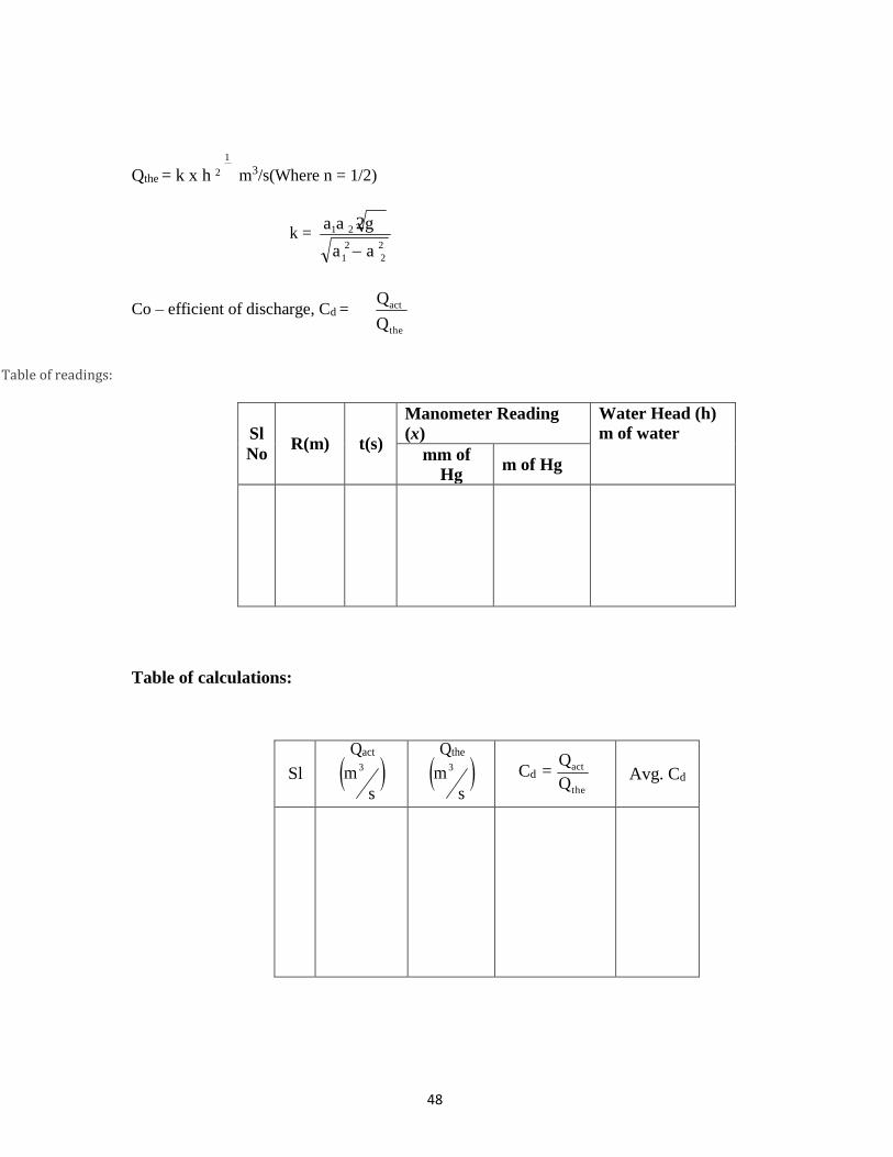
Qthe = k x h 2
m3/s(Where n = 1/2)
x = Manometer reading in m of Hg
k = a1a 2
2
1
2g
a 2
Co – efficient of discharge, Cd = Qact
Qthe
Table of readings:
Sl R
(m)
t
(s)
Manometer reading x
Water Head (h)
m of water
mm m
Table of calculations:
Sl
Qact
m 3 s
Qthe
m 3 s
Cd = Qact
Qthe
Avg. Cd
a

41
Work Sheet
Date: Signature of Faculty

42
d
d
s
VENTURIMETER
BUTTERFLYVALVE
WATERLEVELINDICATOR
MANOMETER
TUBE
BALLVALVE
COONTROLVALVE
SUMP PUMP
EXPERIMENTALSETUP
Observation and Calculation:
Inlet diameter of venturimeter, d1 = m Throat diameter of venturimeter, d2 = m
Area of Collecting Tank, A = m2
Formulae:
Cross sectional area of inlet, a1 =
Cross sectional area of throat, a2 =
2
1 m2
4 2
2 m2
4
Actual discharge Qact = AR m
3
where R = rise in water level in collection tank (in m). t
Theoretical discharge, Qthe =
m3
where head, h = x SHg
s S
1
m of water.
w
x = Manometer reading in m of Hg
a1a 2 2gh
a 2 a
2 1 2

43
Experiment No. 05 VENTURIMETER.
Aim: To determine the co-efficient of discharge through Venturimeter.
Theory:
Venturimeter is a device used to measure discharge of fluid in a closed conduit or pipeline. It
consists of a convergent cone, throat and divergent cone. As the area of the flow decreases in the
convergent cone, velocity of flow increases and pressure decreases. The measurement of pressure difference between the inlet section and throat section leads to the measurement of discharge. The angle
of divergent cone will be 600 and that of convergent cone will be about 200. The length of the divergent cone will be more than the length of convergent cone. The dia of the throat will be 0.5-0.6 times the dia of the pipeline or the inlet section.
If a fluid is made to flow through a varying section due to the variation in pressure, there will be variation in velocity and this effect is known as venture effect.
Apparatus used:
1. Venturimeter 2. Pump and motor for steady supply of water. 3. Clock to record the time 4. Measuring tank.
Procedure:
1. Fill the sump with clean water. Keep the delivery valve closed. Open the
ball valve of the venturimeter pipeline.
2. Adjust the flow through the control valve of pump.
3. Open the corresponding ball valve fitted to Venturi meter tank tappings.
4. Care should be taken, such that there should be not any air bubble, while the liquid
is passing through the manometer.
5. The differential reading of the manometer is noted down from the level of Hg in two limbs.
6. Then the time required to collect 200 mm of water in the collecting tank is noted down.
7. Finally the procedure is employed for different discharge through the pipeline.
Graph to be plotted
Log Qact Vs logh and calculate the slope

44
2
1
Qthe = k x h 2
m3/s(Where n = 1/2)
k = a1a 2
2
1
2g
a 2
Co – efficient of discharge, Cd = Qact
Qthe
Table of readings:
Sl
No
R(m)
t(s)
Manometer Reading (x)
Water Head (h)
m of water
mm of Hg
m of Hg
Table of calculations:
Sl
Qact
m 3 s
Qthe
m 3 s
Cd = Qact
Qthe
Avg. Cd
a

45
Work Sheet
Date: Signature of Faculty

46
d
d
s
NOZZLEMETER
BUTTERFLYVALVE
WATERLEVELINDICATOR
MANOMETER
TUBE
BALLVALVE
COONTROLVALVE
Observation and Calculation:
Inlet diameter of Nozzle, d1 = m Exit diameter of Nozzle, d2 = m
Area of Collecting Tank, A = m2
Formulae:
Cross sectional area of inlet, a1 =
2
1 m2
4
Cross sectional area of exit, a2 =
2
2 m2
4
Actual discharge Qact = AR m
3
where R = rise in water level in collection tank (in m). t
Theoretical discharge, Qthe =
m3
where head, h = x SHg
s S
1
m of water.
w
a1a2 2gh
a 2 a
2
1 2

47
x = Manometer reading in m of Hg
Experiment No. 06 FLOW NOZZLE APPARATUS.
Aim: To determine the co-efficient of discharge through a nozzle meter.
Theory:
Flow nozzle is a device used to measure discharge of fluid in a closed conduit or pipeline. It is
mainly used for metering fluids flowing under high pressure thorough lines of minimum size due to some
reason, another advantage of flow nozzle is that it requires smaller piping before & after the primary
element as compared that of an orifice meter.
Apparatus used:
1. Nozzle meter 2. Pump and motor for steady supply of water. 3. Clock to record the time 4. Measuring tank.
Procedure:
1. Fill the sump with clean water. Keep the delivery valve closed. Open the ball valve of the venturimeter pipeline.
2. Adjust the flow through the control valve of pump.
3. Open the corresponding ball valve fitted to Venturi meter tank tappings.
4. Care should be taken, such that there should be not any air bubble, while the liquid
is passing through the manometer.
5. The differential reading of the manometer is noted down from the level of Hg in two limbs.
6. Then the time required to collect 200 mm of water in the collecting tank is noted down.
7. Finally the procedure is employed for different discharge through the pipeline.
Graph to be plotted
Log Qact Vs logh and calculate the slope
48
1
Qthe = k x h 2
m3/s(Where n = 1/2)
k =
Co – efficient of discharge, Cd = Qact
Qthe
Table of readings:
Sl
No
R(m)
t(s)
Manometer Reading
(x)
Water Head (h)
m of water
mm of
Hg m of Hg
Table of calculations:
Sl
Qact
m 3 s
Qthe
m 3 s
Cd = Qact
Qthe
Avg. Cd
a1a 2 2g
a 2 a
2
1 2

49
Work Sheet
Date: Signature of Faculty

50
WATER
60°
V- NOTCH
V- NOTCH
V- NOTCH HOOKGAUGE
BUTTERFLYVALVE
WATERLEVELINDICATOR
BALLVALVE
COONTROLVALVE
SUMP PUMP
EXPERIMENTALSETUP

51
Experiment No. 07 TRIANGULAR NOTCH
Aim: To Determine the Co-efficient of Discharge through triangular notch and to calibrate given
triangular notch
Theory:
A notch is a device used for measuring the rate of flow of liquid through a small channel (or) a tank.
Applications:
b) For finding the discharge of flowing water.
c) Velocity of flowing water can be determined.
Advantages:
b) Easy to calculate discharge.
c) Can be used in wide channels too.
Disadvantages:
a) Ventilation for notch is necessary.
b) Less accurate results are obtained, while measuring discharge.
Co-efficient of discharge is defined as the ratio of the actual discharge to the theoretical
discharge. It is denoted by Cd.
i,e Cd = Qact
Qthe
Expressions for Qthe for triangular notch(V notch) is given as,
Qthe =
8 tan
5
x H 2
15 2
Apparatus Required:
2. Approach channel with baffle plate fitted with notch,
3. A Surface level gauge to measure head over notch.
4. A measuring tank to measure flow rate.
5. A constant steady supply of water with using pump.
Procedure:
1. Fix the triangular notch at the end of the approach channel with sharp edge on the
upstream side.
2. Fill the channel with water up to the crest level and adjust the hook gauge reading to zero.
3. Adjust the flow by control valve to give maximum possible discharge and wait until
head over the sill of the notch. Note down the final hook guage reading causing flow
over the notch
2g

52
.
Observations and Calculations:
Area of collecting tank (A) = m2
Breadth of tank (b) = m
Angle of V notch () =
Formulae:
Actual discharge, Q
act
=
AR m3
t s
Where, A = Area of collecting tank in metre.
R = Rise of water level in collecting tank in metre. t = time in seconds.
Theoretical discharge, Q
the =
8 tan
15 2
5
x H 2 m3
Where,
H = Head over notch in metre = FR - IR
Co – efficient of discharge, Cd = Qact
Qthe
Graph to be plotted:
Log Qact Vs log H and calculate the slope
Table of Readings:
Sl.
No.
Discharged water Hook gauge reading Head
Over
notch H (m)
R
(m)
t (s)
IR FR
mm m mm m
2g s

53
4) Collect the water flowing over the notch in the measuring tank and measure the rise in
water level „R‟ in the tank for „t‟ sec.
5) Lower the water level in approach channel in stages by varying the flow by control valve and record the series of readings.
Table of Calculations:
Sl
Qact
m 3 s
Qthe
m 3 s
Cd = Qact
Qthe
Avg. Cd
Date: Signature of Faculty

54
PUMP
Pelton Wheel
VALVE
COLLECTINGTANK
VALVE
PELTONWHEEL
BRAKEDRUM
WATERLEVEL INDICATOR
BUCKET
HOOKGAUGE
VNOTCH
COLLECTINGTANK
SPEARROD
SUMP EXPERIMENTALSETUP
A NOTE ON THE DESIGN OF PELTON TURBINE
DATA:
* Maximum head available on turbine(H) = 50 m
* Maximum flow rate available through runner(Q) = 0.005 m3 / s
* Runner Diameter (D) = 0.31 m
* Number of Buckets = 20 no‟s
APPARATUS:
a) Centrifugal pump set, sump tank, notch tank, turbine, piping to operate the turbine on closed
circuit water circulating system
b) Digital RPM indicator, pressure gauge, flow control valve, mechanical loading with Spring
balance

55
Experiment No. 08
PELTON TURBINE TEST RIG
(MECHANICAL BRAKEDRUM LOADING)
AIM:
1) To study the working principle of Pelton (impulse) turbine
2) To understand the functional aspects of various components constituting the turbine
3) To study performance characteristics of turbine at various heads, speed and load.
INTRODUCTION:
Hydraulic (or water) Turbines are the machines, which use the energy of water (Hydro –power) and
convert it into Mechanical energy. Thus the turbine becomes the prime mover to run the electrical
generators to produce the electricity, viz., hydroelectric power.
The Turbines are classified as impulse & reaction types. In impulse turbine, the head of water is
completely converted into a jet, which impinges on the turbine runner, it is the pressure of the flowing
water, which rotates the runner of the turbine. Of many types of turbines, the Pelton turbine, most
commonly used, falls into the category of impulse turbine while the Francis & Kaplan falls into the
category of reaction turbines.
Normally, Pelton turbine (impulse) requires high heads and low discharge, while the Francis &
Kaplan (reaction turbines) require relatively low heads and high discharge. These corresponding heads
and discharges are difficult to create in laboratory size turbine as the limitation of the pump‟s availability
in the market. Nevertheless, at least the performance characteristics could be obtained within the limited
facility available in the laboratories. Further, understanding various elements associated with any
particular turbine is possible with this kind of facility.
DESCRIPTION:
The experimental setup consists of Centrifugal pump set, Turbine unit, sump tank, notch tank
arranged in such a way that the whole unit works as recirculation water system. The centrifugal pump set
supplies the water form the sump tank to turbine through control valve situated on the pump and a sphere
valve before entering the turbine. The water after passing through the Turbine unit enters the Notch tank
and then flows back to sump tank through the Notch tank which is fixed with a notch plate for
measurement of flow rate.
The loading of the turbine is achieved by a brake drum with rope & spring balance, provision for
measurement of turbine speed (digital RPM indicator), Head on turbine (pressure gauge) are built in on
the control panel.

56
SPECIFICATION:
Supply pump capacity : 7.5Hp, 3ph, 440V
Turbine capacity : 1.1 kW
Run away speed : 1500 rpm
Loading : Brake drum with spring balance
OBSERVATION TABLE:
Constant Speed:
Sl
No Turbine
speed
‟N‟ rpm
Pr
Gauge
reading
„P‟
Kg/cm2
Head
over
turbine
„H‟ in
m
Head over
the notch
h2-h1=h in
m
Spring
balance
reading Kg
Flow rate „Q‟
m3/s
Input
power
kW
Brake
power
Bp
kW
Turbine
efficiency
% η turb
S2-S1= S

57
PROCEDURE:
1) Connect the panel to the electrical source & ascertain the direction of the pump is in
order (clock wise direction from shaft end) by momentarily starting the pump.
2) Fill filtered clear water into the sump tank up to ¾th its full capacity
3) Keep the control valve situated above the pump in fully closed position, and the
sphere valve in half open position.
4) Start the pump; gradually open the control valve slowly so that the turbine achieves
sufficient speed.
5) Wait till the speed of the turbine maintained constant. 6) Load the turbine by turning the hand wheel situated on the load frame clock wise
observing the dial spring balance to any desired minimum load
7) Allow the turbine speed to stabilize 8) Record the readings indicated on pressure gauge, dial balance RPM indicator and
head over the notch plate
9) Continue loading the turbine in steps up to its full load and record the corresponding readings at each steps
10) After the experiment is over bring the turbine to no load condition by rotating the hand wheel on the load frame in anti clock wise direction and stop the pump.
11) Tabulate all the recorded readings and calculate the input power, output power & efficiency of the Turbine.
Graphs to be plotted:
Main Characteristics Curves (constant Head) 1. Qu Vs Nu 2. Pu Vs Nu
3. o Vs Nu
Operating Characteristics Curves (Constant Speed)
4. o Vs % full load.

58
Constant Head:
Sl No
Turbine
speed
‟N‟ rpm
Pr
Gauge
reading
„P‟
Kg/cm2
Head
over
turbine
„H‟
meters
Head over
the notch
h2-h1=h
meters
Spring
balanced
reading Kg
Flow rate „Q‟
m3/s
Input
power
kW
Brake
power
Bp
kW
Turbine efficiency
%
ηturb
S2-S1= S
CALCULATIONS:
1. Head on turbine H:
H = 10 x P where P is the pressure gauge reading in Kg/cm2
h3/2 m3/sec
b = Width of notch in m h = Head over the notch in m
3. Input power = WQH / 1000 kW where W = 9810 N/m3
2. Flow rate of water, Q = 2/3 Cd b √2g
g = 9.81 m/sec2
Cd = 0.9

59
4. Brake power
BP = 2N (S2-S1) r x 9.81 / 60 x 1000 kW
Where r = Radius of the brake drum = 0.168 m(0.152+. 016)
5. Turbine efficiency
ηturb = BP / IP x 100
6. Unit speed, Nu = N
H
7. Unit discharge, Qu = Q
H
8. Unit power, Pu = Pshaft
3
H 2
9. Specific speed, Ns = N Pshaft
5
H 4
Date: Signature of Faculty

60
A NOTE ON THE SPECIFICATION OF FRANCIS TURBINE
Data:
* Maximum head available on turbine (H) = 05- 09 m.
* Maximum flow rate available through Impeller (Q) = 0.035 m3 / s
= 1200- 1500 lit / min
* Impeller Diameter (D) = 150 mm
* Number of Guide vanes = 8 No„s (adjustable)
Apparatus:
c) Centrifugal pump set, sump tank, turbine, piping system with Venturimeter to operate the
Turbine on closed circuit water circulating system.
d) Digital RPM indicator, Digital Voltmeter, Ammeter, pressure gauge, flow control valve, with
suitable electrical dynamometer loading with resistance bank (heaters), with switches, fan to
decipate heat.
TUBES
VENTURIMETER
CENTRIFUGALPUMP
PRESSUREGAUGE BRAKEDRUM
FRANCISTURBINE
VALVE PRESSUREGAUGE MANOMETER
DRAFTTUBE
EXPERIMENTALSETUP SUMP

61
Experiment No. 09 FRANCIS TURBINE TEST RIG
(USING VENTURIMETER)
INTRODUCTION:
Hydraulic (water) Turbines are the machines, which use the energy of water (Hydro –power) and convert
it into Mechanical energy, which is further converted into electrical energy. Thus the turbine becomes
the prime mover to run the electrical generators to produce electricity (Hydroelectric power).
The Turbines are classified as impulse & reaction types. In impulse turbine, the head of water is
completely converted into a jet, which exerts the force on the turbine; it is the pressure of the flowing
water, which rotates the Impeller of the turbine. Of many types of turbine, the Pelton wheel, most
commonly used, falls into the category of impulse turbine, while the Francis & Kaplan falls into the
category of reaction turbines.
Normally, Pelton wheel (impulse turbine) requires high heads and low discharge, while the Francis &
Kaplan (reaction turbines) require relatively low heads and high discharge. These corresponding heads
and discharges are difficult to create in laboratory because of the limitation of required head &
discharges. Nevertheless, an attempt has been made to study the performance characteristics within the
limited facility available in the laboratories. Further, understanding various elements associated with any
particular turbine is possible with this kind of facility.
DESCRIPTION:
While the impulse turbine is discussed elsewhere in standard textbooks, Francis turbine (reaction type)
which is of present concern consists of main components such as Impeller (runner), scroll casing and
draft tube. Between the scroll casing and the Impeller there are guide vanes, which guides the water on to
the impeller thus rotating the Impeller shaft. There are eight guide vanes, which can be turned about their
own axis so that the angle of inclination may be adjusted while the turbine is in motion. When guide vane
angles are varied, high efficiency can be obtained over wide range of operating conditions.
The actual experiment facility supplied consists of a sump tank, centrifugal pump set, turbine unit and
Venturimeter arranged in such a way that the whole unit works on recirculating water system. The
centrifugal pump set supplies the water from the sump tank to the turbine through control valve (Gate
valve). The water from the pump passes through a Venturimeter (for measurement of discharge) to the
turbine unit enters the sump tank through the draft tube.
The loading of the turbine is achieved by electrical dynamometer coupled to the turbine through a V-
Belt drive (V grooved pulley). The control panel is equipped with a set of heaters (electrical resistance)
in steps of 200Vats each, 10 No. (200 x 10 Total 2Kw) with individual switches are provided for loading
the electrical dynamometer (in turn loading the turbine). The provisions for measurement of load (by
digital Voltmeter & Ammeter), turbine speed (digital RPM indicator),

62
differential pressure across Venturimeter (Double column Mercury Manometer) & total head on
turbine (pressure & vacuum gauge).
Specification:
Supply pump capacity : 7.5 Kw (10 Hp) 3ph, 400V
Turbine capacity : 2.6 HP (2 Kw)
Run away speed : 2000 RPM
TABULAR COLUMN
Constant Speed:
Sl No
Pressure Gauge reading „P‟
Kg/cm2
Head
over the
turbine
„H‟ in m
Presser Gauge reading in
Kg/cm2
Across Venturimeter
h Alternator
Flow rate „Q‟
m3/s
Input
power
Kw
(Ip)
Out put
power
Kw
(Op)
Turbine efficiency
% η turb
h1 h2 V
volts
I
amps

63
Procedure:
1) Install the equipment near a 3 phase 440 volts, 50 Hz, 20 amps power source & water
source.
2) Connect the panel to the electrical source & ascertain the direction of the pump is in order (clock wise direction from shaft end) by momentarily starting the pump.
3) Fill filtered clear water into the sump tank up to ¾th its full capacity.
4) Keep the gate valve situated above the pump in fully closed position, turbine guide
vanes in full open position.
5) Start the pump, gradually open the gate valve slowly so that the turbine achieves
sufficient speed to generate 200 volts on the panel voltmeter.
6) Wait till the speed of the turbine & generated voltage maintained constant. 7) Put on the first electrical load switch and adjust the speed of Turbine to 200V on the
panel Voltmeter and record the corresponding Ammeter, Pressure gauge & Head over
the notch readings.
8) Continue increasing the load on the Turbine step by step by switching ON the
consecutive load switches one by one, by gradually opening the Gate valve so that the
Voltmeter reading shows 200V on each step. Record the corresponding readings of
Ammeter, Pressure Gauge & Head over the notch.
9) Change the Turbine guide vane to any desired position (between fully open to closed
conditions) by operating the hand wheel situated at the rear end of the Turbine to
repeat the experiment on varied condition by following steps 7 & 8.
10) After the experiment is over bring the turbine to no load condition by switching OFF
the load switches one by one and simultaneously closing the Gate valve (care must be
taken to avoid sudden increase in speed / Volts while switching „off ‟ the load
switches) & stop the pump.
11) Tabulate all the recorded readings and calculate the input power, output power &
efficiency of the Turbine.
Note: Drain all the water from the sump tank, refill with fresh clean water once in a month. When the
equipment is not in use for a longer duration, drain all water from the sump tank keep it clean & dry.
Graphs to be plotted:
Main Characteristics Curves (constant Head) 1. Qu Vs Nu 2. Pu Vs Nu
3. o Vs Nu
Operating Characteristics Curves (Constant Speed)
4. o Vs % full load.

64
Constant Head:
Sl
No
Pressure Gauge reading „P‟
Kg/cm2
Head
over the
turbine
„H‟ in m
Presser Gauge
reading in
Kg/cm2
Across
Venturimeter
h Alternator
Flow rate „Q‟
m3/s
Input
power
Kw
(Ip)
Out put
power
Kw
(Op)
Turbine
efficiency
% η turb
h1 h2 V volts
I amps
CALCULATION
Out put power Op =
V x I ηGen = 0.75
1000 x ηGen
W Q H
Input power Ip = where: w = 9810 n/ m3
1000
Q = Cd k√ 2 g h w a1 a2
K = √ a2
1 – a2
Cd=0.94
Out put power
Turbine efficiency η Tur = x 100 % Input power
Unit speed, Nu = N
H
Unit discharge Qu = Q
H
2

65
Unit power, Pu = Pshaft
3
H 2
Specific speed, Ns = N Pshaft
5
H 4
Date: Signature of Faculty

66
ORIFICEMETER WATERFILL LOADING
CENTRIFUGALPUMP
TUBE KAPLANTURBINE
VANE ADJUSTING MECHANISM
Kaplan Turbine
A NOTE ON THE SPECIFICATION OF KAPLAN TURBINE
DATA:
* Maximum head available on turbine(H) = 9 - 12 m.
* Maximum flow rate available through runner(Q) = 0.05 m3 / s
= 3000 lit / min
* Propeller Diameter (D) = 150 mm
* Number of Propeller Blades = 4 No‟s (adjustable)
* Hub Diameter (d) = 60 mm
APPARATUS:
a. Centrifugal pump set, sump tank, turbine, piping system to operate the
Turbine on closed circuit water circulating system
b. Digital RPM indicator, pressure gauge, flow control valve, with suitable electrical dynamometer loading with resistance bank (heaters), switches, fan to dissipate heat form the
resistance (heaters) load

67
Experiment No. 10
KAPLAN TURBINE TEST RIG
(USING ORFICE METER)
AIM:
1. To study the working principle of Kaplan (reaction) turbine.
2. To understand the functional aspects of various components constituting the turbine. To study performance characteristics of turbine at various heads, flow rates and speeds
INTRODUCTION:
Hydraulic (water) Turbines are the machines, which use the energy of water (Hydro –power) and convert
it into Mechanical energy, which is further converted into electrical energy. Thus the turbine becomes
the primover to run the electrical generators to produce electricity (Hydroelectric power).
The Turbines are classified as impulse & reaction types. In impulse turbine, the head of water is
completely converted into a jet, which exerts the force on the turbine; it is the pressure of the flowing
water, which rotates the runner of the turbine. Of many types of turbine, the Pelton wheel, most
commonly used, falls into the category of impulse turbine, while the Francis & Kaplan falls into the
category of reaction turbines.
Normally, Pelton wheel (impulse turbine) requires high heads and low discharge, while the
Francis & Kaplan (reaction turbines) require relatively low heads and high discharge. These
corresponding heads and discharges are difficult to create in laboratory because of the limitation of
required head & discharges. Nevertheless, an attempt has been made to study the performance
characteristics within the limited facility available in the laboratories. Further, understanding various
elements associated with any particular turbine is possible with this kind of facility.
DESCRIPTION:
While the impulse turbine is discussed elsewhere in standard textbooks, Kaplan turbine (reaction type)
which is of present concern consists of main components such as propeller (runner), scroll casing and
draft tube. Between the scroll casing and the runner, the water turns through right angle into axial
direction and passes over the runner and thus rotating the runner shaft. The runner has four blades, which
can be turned about their own axis so that the angle of inclination may be adjusted while the turbine is in
motion. The runner blade angles can be varied to obtain higher efficiency over wide range of operating
conditions. In other words even at part loads, when a low discharge is flowing over the runner, a high
efficiency can be attained in case of Kaplan turbine. Where as this provision does not exist in Francis &
Propeller turbines where the runner blade angles are fixed and integral with the hub.

68
The actual experimental setup consist of a centrifugal pump set, turbine unit, sump tank, arranged in
such a way that the whole unit works on recirculating water system. The centrifugal pump set
Specification:
Supply pump capacity : 7.5 Kw (10 Hp) 3ph, 400V
Turbine capacity : 2.6 HP (2 Kw)
Run away speed : 2000 RPM
OBSERVATION TABLE
CONSTANT SPEED:
Sl
No
Turbine
speed
‟N‟ rpm
Pr Gauge
reading
„P‟
Kg/cm2
Head
over
turbine
„H‟ in
m
Manometer
reading
Load Flow
rate
„Q‟
m3/s
Input
power
kW
Brake
power
Bp
kW
Turbine
efficiency
%
ηturb
Voltage V
Volts
Current I
Amps L1 L2
1
2
3
4
5
CONSTANT HEAD:
Sl
No
Turbine
speed
‟N‟ rpm
Pr Gauge
reading
„P‟
Kg/cm2
Head
over
turbine
„H‟
meters
Manometer
reading
Load Flow
rate
„Q‟
m3/s
Input
power
kW
Brake
power
Bp
kW
Turbine
efficiency
%
ηturb
Voltage
V
Volts
Current
I
Amps L1 L2
1
2
3
4
5

69
supplies the water from the sump tank to the turbine through control valve (Butterfly valve) and passes
through and orifice meter connected to a double column mercury manometer which facilitates to obtain
the quantity of water discharged form the turbine unit. Water after passing through the turbine unit enters
the sump tank through the draft tube.
The loading of the turbine is achieved by electrical dynamometer coupled to the turbine through
a V- Belt drive (V grooved pulley). A set of heaters (electrical resistance) in steps of 200 Watts each, 10
no. (Total 2Kw) with individual switches provided for loading the electrical dynamometer (in turn
loading the turbine). The provisions for measurement of turbine speed (digital RPM indicator), head on
turbine (pressure gauge) are built-in on the control panel.
OPERATING PROCEDURE:
Install the equipment near a 3 phase 440 volts, 50 Hz, 20 amps power source &water source.
1. Connect the panel to the electrical source & ascertain the direction of the pump is in order (clock
wise direction from shaft end) by momentarily starting the pump.
2. Fill filtered clear water into the sump tank &discharge tank upto the flow channel level.
3. Keep the butterfly valve situated above the pump in partially closed position & turbine runner
blade in full open position.
4. Start the pump, gradually open / close the butterfly valve so that the turbine achieves sufficient speed to generate 220volts on the panel voltmeter
5. Wait till the speed of the turbine & generated voltage maintained constant.
6. Open all the valves provided on the manometer fully and the valves across the orifice meter
partially to release the air trapped in the manometer and observe water flowing through the air
vent tubes.
7. Close both the air vent valves simultaneously and read the difference of mercury level in the
manometer limbs to obtain the discharge.
8. Switch “ON” the first two electrical load switches and adjust the speed of Turbine to 220V on
the panel Voltmeter by adjusting the flow control valve and record the corresponding Ammeter,
Pressure gauge and manometer readings.
9. Continue increasing the load on the Turbine step by step by switching “ON” the consecutive load
switches in sets of two and maintain the panel voltmeter reading at 220V by adjusting the flow
control valve accordingly.
10. Record the relative voltmeter, ammeter, pressure gauge and manometer readings on each step.
11. Bring the Turbine to no load condition by switching OFF the load switches in steps. 12. Change the Turbine Runner position by operating the hand wheel situated at the rear end of the
Turbine & repeat the experiment following the steps 10 to 12.
13. After the experiment is over bring the turbine to no load condition & stop the pump. 14. Tabulate all the recorded readings and calculate the output power, input power & efficiency of
the Turbine.

70
2
CALCULATIONS:
1. Head on turbine H :
H = 10 x P where P is the pressure gauge reading in Kg/cm2
Cd x a1 x a2
Flow rate of water Q = x 2gh m3/s
a12 - a 2
Where g = 9.81 m/s2
Cd = 0.62
a1 =
a2 =
h = (l2 – l1 )x 12.6 m.
ρhg - ρw
Where x (l2 – l1) m
ρw
2. Input power (Hydraulic power input to Turbine)
Ip = WQH Kw where W = 9810 N/m3
1000
3. Output power
Op = V x I Kw Where η gen = 0.7 1000 x η gen
4. % Turbine efficiency
ηturb = Output power x 100
Input power
Unit speed, Nu = N
H
Unit discharge Qu = Q
H
Unit power, Pu Pshaft
3
H 2
Specific speed, Ns
N Pshaft
5
H 4
= =

71
Graphs to be plotted:
Main Characteristics Curves (constant Head) 1. Qu Vs Nu
2. Pu Vs Nu
3. o Vs Nu
Operating Characteristics Curves (Constant Speed)
4. o Vs % full load.
Date: Signature of Faculty

72
WATERLEVEL INDICATOR
EXPERIMENTALSETUP
SPECIFICATIONS:
Single stage pump with Motor
Sump tank:
MOC: Stainless Steel,
Measuring tank:
MOC: Stainless Steel
Area of cross section: 0.125 m2 (Measuring tank)
Drive Belt Size: - A-26
DELIVERYPIPE
VALVE DCMOTOR
COUPLING BRAKEDRUM
CENTRIFUGALPUMP
SUCTIONPIPE
COLLECTINGTANK
TUBE
FOOTVALVEANDSTRAINER SUMP

73
Experiment No. 11
SINGLE STAGE CENTRIFUGAL PUMP
AIM: To conduct performance test on a Single stage Centrifugal pump test rig.
INTRODUCTION:
A pump may be defined as mechanical device when interposed in a pipe line, converts the mechanical
energy supplied to it from an external source into hydraulic energy, thus resulting in the flow of liquid
from lower potential to higher potential.
The pumps are of major concern to most engineers and technicians. The types of pumps vary in principle
and design. The selection of the pump for any particular application is to be done by understanding their
characteristics. The most commonly used pumps for domestic, agricultural and industrial are Centrifugal,
axial flow, reciprocating, air jet, and diaphram and turbine pumps. Most of these pumps fall into the main
class namely Rotodynamic, Reciprocating (positive displacement) and Fluid operated pumps.
THEORY:
The principle of operation of a single stage centrifugal pump is covered under Rotodynamic pump
category. In this pump, the liquid is made to rotate in a closed volute chamber. Thus creating the
centrifugal action, which gradually builds the pressure gradient towards outlet resulting in a continuous
flow.
These pumps are of simple construction can be directly coupled to electric motor and more suitable for
handling clear, semi viscous, as well as turbid liquids. The hydraulic head per stage at low flow rates is
limited and hence not suitable for high heads, in case of single stage centrifugal pumps. But as the pump
in this case in a multi stage construction the pressure gradually builds up in successive stages almost
equally in each stage. Thus achieving considerably higher heads. The multi stage centrifugal pump test
rig allows the students to understand and study the various characteristics and pressure build up pattern
in individual stages.
DESCRIPTION:
The single stage Centrifugal pump test rig mainly consists of:
a) Single stage Centrifugal pump
b) AC Drive motor of suitable capacity coupled to pump by stepped pulley arrangement.
c) SS sump tank and measuring tank with a piezometer
d) G. I. Pipe connections with necessary control valve etc… mounted on a neatly painted M.S.
structure. The panel board is equipped with an energy meter for measurement of power input to
the motor, a digital RPM indicator to indicate the speed of the pump/motor, a Vacuum gauge to
measure suction head, & pressure gauge for measurement of delivery head, a starter of suitable
capacity, indicating lamps and fuse etc.

74
CALCULATIONS:
Basic data / constants: 1 kg / cm2
=
760 mm Hg (10 m of water)
Density of water = 1000 kg / m3 ( 9810 N / m 3 )
Area of collecting tank = 0.125 m2
Discharge rate “ Q ” in m3 / s Q = A x h
t
where „h‟ is height of water collected in measuring tank for a time interval of „t‟ sec.
Total head “ H ” in m
H = 10(Delivery Pressure + Vacuum head)
= 10(P + Pv )
where P is pressure in kg / cm2 , Pv is the Vacuum in mm of Hg
p=(1.032+ pressure reading) Pv=(1.032- (suction pressure reading x 1.33 x 10⁻³) )
Power input to motor (kW)
Data: Energy meter constant E.M.C. = 3200 Rev/kw-h
K 60 x 60
I.P = X X motor = kW.
E.M.C. t
Where ηmotor = 0.70, (70 %)
Where „K‟ is the number of revolutions energy meter disc = 10 rev
„t‟ is the time taken in seconds by the Energy Meter for K revolutions
„m‟ = motor efficiency 0.70 (70% )
(1hp = 0.736 kW) (1 kW = 1.36 hp.)
Output Power ( delivered by the pump) kW
= W x Q x H kW 1000
Where W is 9810 N/m3
% ηpump = Out power x 100 Q is Discharge
Input power

75
Table of readings:
Suction Time taken Water level
Speed Delivery pressure for 10 rise in tank Discharge N pressure p Pv Impulse of R time
(rpm) (kgf/cm2) mm of energy meter t (s)
mm m Hg (te) s
Table of calculations:
Speed of
pump
N
(rpm)
Head
H
m of
water
Discharge
Q
(m3/s)
Power
input to
pump
Pin
(kW)
Power
developed by
pump Pp
(kW)
Overall
efficiency
o
(%)
Date: Signature of Faculty

76
EXPERIMENTALSETUP
CALCULATIONS:
Basic data / constants:
1kg/cm2 = 760 mm Hg (10 m of water)
Density of water = 1000 kg / m3
Area of collecting tank = 0.125 m2
Discharge rate “ Q ” in m3 / s
Q = A x h
t
where „h‟ is height of water collected in measuring tank for a time interval of „t‟ sec.
Total head “ H ” in m
PD=1.032 + Reading
PV=1.032 – (Reading x 1.315 x 10⁻³)
H = 10 ( Delivery Pressure + Vacuum head ) = 10 ( PD + Pv )
where PD is pressure in kg / cm2 , Pv is the Vacuum in mm of Hg
DELIVERYPIPE DELIVERYVALVE
LOADINDICATOR
WATERLEVEL INDICATOR
COLLECTINGTANK
BELT
SUCTION VALVE
DCMOTOR
SUCTIONPIPE
RECIPROCATINGPUMP
SUMP

77
Experiment No. 12
RECIPROCATING PUMP TEST RIG
AIM: To study the performance and characteristics of reciprocating pump and to determine the efficiency of
the pump
INTRODUCTION:
In general, a pump may be defined as mechanical device when connected in a pipe line, can convert the
mechanical energy into hydraulic energy, thus resulting in the flow of liquid from lower potential to
higher potential.
The pumps are of major concern to most engineers and technicians. The types of pumps vary in principle
and design. The selection of the pump for any particular application is to be done by understanding their
characteristics. The most commonly used pumps for domestic, agricultural and industrial are Centrifugal,
axial flow (stage pumps), reciprocating, air jet, and diaphram and turbine pumps. These pumps fall
mainly into a category of rotodynamic, reciprocating (positive displacement) and fluid operated pumps.
THEORY:
Reciprocating pump is a positive displacement pump. It mainly consists of a piston reciprocating inside a
cylinder thus performing suction and delivery strokes. The cylinder is alternately filled and emptied by
forcing and drawing the liquid by mechanical motion. This type is called positive type. Delivery and
suction pipes are connected to a cylinder. Each of the two pipes is provided with a non- return valve. The
function of which is to ensure unidirectional flow of liquid. It generally operates at low speed and is
therefore to be coupled to a motor with V-belt. It is stable for small discharge and high heads. Generally
these pumps are used for feeding small boilers, for lifting water to a higher heads & for pumping light
oil. The present test rig allows the students to understand and draw the operating characteristics at
various heads, flow rates and speeds. DISCRIPTION:
The Reciprocating pump test rig mainly consists of:
a) Double stroke Reciprocating pump
b) AC Drive motor of suitable capacity coupled with a belt drive Variable speed stepped cone
pully.
c) SS sump tank, SS measuring tank with a piezometer
d) G. I. Pipe connections with necessary control valve etc… mounted on a neatly painted M.S. structure.
e) The panel board is equipped with an energy meter for measurement of power input to the motor,
a digital RPM indicator to indicate the speed of the pump, a Vacuum gauge to measure suction
head , a pressure gauges for measurement of delivery head. a three phase starter of suitable
capacity, main indicating lamps and fuses.

78
INPUT POWER (IP): Data:
Energy meter constant E.M.C.= 1600 Imp / kw / h
(IP) = n x 60 x 60 x m
K t
where „n‟ is the number of impulse of energy meter
„t‟ is the time taken in seconds by the Energy Meter for n impulses „m‟ =
motor efficiency 0.72 (72% )
Output Power ( delivered by the pump)
= W x Q x H
1000 where W is 9180 N/m3
% η overall = Output power x 100
Input power TABULAR COLUMN :
Drive Belt Size- B-53.
Sl.. No.
Speed of pump in rpm
Suction
pressure
„Pv‟ (mm of Hg)
Delivery pressure
„P‟
Kg /cm2
Energy meter reading for 10 pulses.
„t‟
in sec‟s
10 cm raiseof
water level in
collecting tank
„T‟ in sec‟s
1.
2.
3.
4.
Calculated readings: Sl.No. I.p.
(kW)
Discharge
„Q‟
m³ / Sec
Head „H‟ in
mts of water
O.p.= WQH 1000
(kW)
% =
Op/Ip x 100
1
2

79
Procedure:
1. Connect the power cable to three phase, 440 volts, 10 Amps with earth connection
2. Fill water in air vessel.
3. Keep the delivery valve fully open.
4. Fill the sump tank with clean soft water.
5. Select the desired speed by adjusting the step cone pulley - motor base handle.
6. Switch on the mains, the mains on indicators glow, now switch on the pump, water starts flowing
to the measuring tank.
7. Note down the pressure gauge, vacuum gauge reading and time for number of revolutions of
energy meter disc at full opening of delivery valve.
8. Operate the butterfly valve to note down the collecting tank reading against the known time, and
keep it open when the readings are not taken.
9. Repeat the experiment for different openings of delivery valve and note down the readings as
above
10. Repeat the experiment for different speeds and repeat the steps from 5 to 8.
11. Tabulate the readings.
12. After the experiment is over switch off the mains and keep the delivery valves fully open.
13. Calculate the efficiency of the pump.
Date: Signature of Faculty

80
EXPERIMENTALSETUP
SPECIFICATION:
Type : Two Stage two Cylinders with Inter Cooler.
Motor : 3HP AC.
Max. Working Pressure: 07 kg / cm2
Cylinder Bore : LP Cylinder: 70 mm dia
HP Cylinder: 50 mm dia.
Stroke : 85 mm
TO ORIFICE
PRESSUREGAUGE
COMPRESSOR AIRFILTER
INTERCOOLER MANOMETER
PRESSUREGAUGE
RELEASE VALVE
MOTOR
BELT
TANK

81
Experiment No. 13
RECIPROCATING AIR COMPRESSOR TEST RIG
(TWO STAGE)
AIM OF THE EXPERIMENT:
a) To study the working of two Stage Reciprocating Air Compressor.
b) Determination of Volumetric Efficiency.
INTRODUCTION:
Compressed Air is a form of Energy used extensively for such operations as Pneumatic Machines &
Tools, Material Handling, Construction, Mining, etc. Compressor is a device used to compress air to a
pressure higher than the atmosphere. Generally, Compressors fall into any of the following categories
namely reciprocating and rotary Compressor.
This Manual describes the Working of the two Stage Reciprocating Air Compressor and its
performance.
Procedure:
1) Release all the air from the tank and close the outlet valve.
2) Ascertain sufficient measuring fluid in U tube manometer.
3) Switch – ON the mains and observe the indicators glow.
4) Keep the outlet valve closed.
5) Switch – ON the starter and run the compresses.
6) Open the valves provided on LP and HP Cylinders Connected to the respective pressure
gauges on the panel in such a way that the fluctuation of the needle is arrested.
7) Maintain the pressure at 1 Kg / cm2 by adjusting the outlet valve and record the following
readings: manometer deference, time for n revolution of energy meter, temperatures at 1, 2,
3, & 4 position RPM, LP and HP gauge pressure.
8) Stop the compressor and release all the air form the tank. 9) Tabulate the readings and calculate volumetric efficiency.

82
a
1
CALCULATION:
DATA:
Density of air ρa = 1.293 kg/m3
Density of water ρw = 1000 kg/m3
Acceleration due to Gravity =9.81 m / s2
Orifice Diameter =15 mm.
Co–efficient of Discharge of Orifice =0.62
Volumetric Efficiency,
Va
% η vol = x 100
Vs
Where: Va is actual volume of air compressed
Qact = Va = Cd ao 2 g ha m3 / sec
ao=Area of Orifice = ( / 4) d2 d = Dia of orifice = 20 mm
ha hw w
Qtheo = Vs = swept volume
= ( / 4) D2 x Stroke length x Compressor speed / 60 m3 / s D = Bore Dia of Lp cylinder (70 mm or 0.07m)
OBSERVATIONS TABLE
SI No
Pressure gauge
reading
Time for „η‟
Revolution of
energy meter
Disc in sec
T
Manometer reading
Across orifice in mm
Speed of
compressor
in
RPM
Temperature
Stage
Tank
1
Stage
Tank
2
h1
mm h2
mm h = h2- h1
m
T1 T2 T3 T4
Note: Temperature Points,
T1 =Air Intel Temperature.
T2 =After first stage
T3 =After Intel Cooler.
T4 =After Second Stage.

83
Orifice Dia =20 mm.
TABLE OF CALCULATIONS:
SI No Discharge
Qact
m3 / s
Discharge QTheo
m3 / s
Volumetric
Efficiency
ηvol
%
Date: Signature of Faculty

84
TUBESFROMORIFICE
MANOMETERS
SUCTIONPIPE
LOADING
TUBES
CONTROLVALVE
CENTRIFUGALBLOWER DELIVERYPIPE
PITOT
VENTURIMETEREXPERIMENTALSETUP
CALCULATION
1 Discharge
Q = A x V m3/s
Where V = average of anemometer Readings
C.S Area of the duct = 0.12m2
2. Input power of A/C Motor
n x 60x 60 where : n = no of energy meter Ip = disc revolutions
k x t
k = energy meter constant
t= time taken for no of in sec k
= 3600 rev / kw-hr

85
Experiment No. 14
CENTRIFUGAL AIR BLOWER TEST RIG
AIM: To study the performance of a centrifugal air blower at various operating conditions
INTRODUCTION:
The equipment has been designed as an experimental unit to study the performance
characteristics of centrifugal Blower at various operating conditions. The test rig mainly consists of
centrifugal blower handling air as the medium of flow and is driven by a foot mounted A.C. Motor. The
test rig has provisions for varying the following parameters like discharge and impellers of the blower.
Three interchangeable impellers (backward, forward, and straight) have also been supplied for studying
the performances. These parameters have been used to draw the standard performance curves; covering
the head Vs flow rate and Efficiency Vs flow rate at constant Speed.
PROCEDURE:
1. Connect the control panel input power cable to 3ph A.C.supply , with neutral and
earth.
2. keep all the Switches /controls in Off position.
3. Switch On the mains and observe the 3ph light indicators glow.
4. Turn the rotary switch clock wise to put on the panel meters.
5. Ascertain sufficient measuring fluid (water) in manometers & the direction of rotation of
the blower as indicated on the casing.
6. Keep the outlet butterfly valve fully open.
7. Switch on the starter so that the motor speed builds up to the rated rpm.
8. Keep the pitot tube half way above the center of the duct.
9. Record all the readings indicated by manometer, energy meter (Time for 2 rev) at valve full
open position.
10. Change the valve to 600 position and record the all readings.
11. Similarly record the readings on 300 and fully closed positions.
12. Tabulate all the readings and calculate.
13. Repeat the experiment on different impellers
14. After the experiment switch off the motor and electrical mains.

86
a 1
3. Output power of blower Op
(Op)Blower =
Wa x Q x H
1000
Wa = 12.65N/m3
a = 1.29kg/m3
Δ H hw w
m
where hw = ∆ H x 768.2 m
H = hw x pitot constant where pitot const. = 5
4. Blower Efficiency
η Blower = 100×
Op Blowe
Ip Blower(Ele)
TABULAR COLUMN OBSERVATION
Type of Impellers backward / forward / straight (Radial)
SI No. Speed of
Blower
RPM
Time for
10 impulse
in sec
Pitot
hw in m
Gate Opening
h1 h2

87
Gate opening Discharge Input power of
AC Motor
Blower output
power Blower Efficiency
Date: Signature of Faculty

88
VIVA QUESTIONS 1. Define density?
It is defined as the ratio of mass per unit volume of the fluid.
2. Define viscosity? It is defined as the property of fluid which offers resistance to the movement of fluid over another
adjacent layer of the fluid.
3. Differentiate between real fluids and ideal fluids? A fluid, which is incompressible and is having no viscosity, is known as ideal fluid while the fluid,
which possesses viscosity, is known as real fluid.
4. What is a venturimeter?
It is a device which is used for measuring the rate of flow of fluid flowing through pipe.
5. What is a notch? A notch is a device used for measuring the rate of flow of a fluid through a small channel or a tank.
6. Define buoyancy? When a body is immersed in a fuid, an upward force is exerted by the fluid on the body.This upward force is equal to the weight of the fluid displaced by the body.
7. Define meta-centre? It is defined as the point about which a body starts oscillating when the body is tilted by a small angle.
8. Define a pump? The hydraulic machine which converts the mechanical energy into hydraulic energy is called a pump.
9. Define centrifugal pump? The pump which converts the mechanical energy in to hydraulic energy, by means of centrifugal force acting on the fluid is known as centrifugal pump.
10. Define reciprocating pump? The pump which converts the mechanical energy in to hydraulic energy by sucking the liquid in to a
cylinder in which a piston is reciprocating ,which exerts the thrust on the liquid and increases its
hydraulic energy is known as reciprocating pump.
11. What is impact of jet means?

89
It means the force exerted by the jet on a plate which may be stationary or moving.
12. What is a turbine? A turbine is a hydraulic machine which converts hydraulic energy in to mechanical energy.
13. What is tangential flow turbine?
If the water flows along the tangent of the runner, the turbine is know as tangential flow turbine.
14. What is radial flow turbine? If the water flows in the radial direction through the runner, the turbine is called radial flow
turbine.
15. State Newton‟s law of viscosity? It states that the shear stress on a fluid element layer is directly proportional to the rate of shear
strain.
16. What are the devices used for pressure measurement? The devices used are manometers, diaphragm pressure gauge, dead weight pressure gauge etc
17. Why blower is used?
Blower is used to discharge higher volume of air at low pressure.
18. State continuity equation? For a fluid flowing through a pipe at all the cross section, the quantity of fluid per second is constant.
19. What are the methods of describing fluid motion? The fluid motion is described by two methods. They are lagrangian method and eulerian method.
20. Where the notches are used? Notches are usually used in tanks or small channels.
21. What is a weir?
Weir is a concrete structure placed in an open channel over which the flow occurs.
22. What do you understand by the term major loss in pipes? When a fluid is flowing through a pipe, some of the energy is lost due to friction, this is termed as
major loss.
23. What do you understand by the term minor loss in pipes? When a fluid is flowing through a pipe, some of the energy is lost due to sudden expansion of pipe, sudden contraction, bend and pipe fitting, these are termed as minor loss.
24. Define the term hydraulic gradient?

90
It is defined as the line which gives the sum of pressure head and datum head of a flowing fluid in a
pipe with respect to some reference line.
25. Define the term total energy line? It is defined as the line which gives the sum of pressure head, datum head and kinetic head of a
flowing fluid in a pipe with respect to some reference line.
26. What is a draft tube? It is a pipe of gradually increasing area which connects the outlet of the runner to the tail race. It is
used for discharging water from the exit of the turbine to the tail race.
27. Define co-efficient of velocity of jet. It is defined as the ratio between the actual velocity of a jet of liquid at vena-contracta and the theoretical
velocity of jet.
28. Define co-efficient of contraction of orifice meter. It is defined as the ratio of the area of the jet at vena-contracta to the area of the orifice.
29. Define co-efficient of discharge of orifice meter. It is defined as the ratio of the actual discharge from an orifice to the theoretical discharge from the
orifice.
30. What is vena-contracta? It is a section at which the stream lines are straight and parallel to each other and perpendicular to
the plane of the orifice.

91
REFERENCES
A textbook of Fluid Mechanics by ”Dr. R.K. Bansal”, Laxmi publications ,2004.
Fluid Mechanics (SI Units), Yunus A . Cengel John M Oimbala, 2nd Ed.,
Tata McGraw Hill, 2006.
Fluid Mechanics and Fluid power Engineer


![INDEX []€¦ · INDEX SI.NO EXPERIMENT DETAILS PAGE 1 ... STUDY AND USE OF HYDRAULIC ELEMENTS 22 6 ... connected from the FRL unit](https://img.pdfslide.net/doc/110x75/5b5b9c827f8b9a01748e6ce7/index-index-sino-experiment-details-page-1-study-and-use-of-hydraulic.jpg)