Embed Size (px)
Citation preview
8-20.GR8Illumination, Traffic Signal Systems, and Electrical
8-20.1.GR8Description
8-20.2.GR8Materials
8-20.2.INST1.GR8Section 8-20.2 is supplemented with the following:
8-20.2.OPT1.ESP.FT1(NWR February 11, 2013)Contracting Agency-Supplied MaterialsThe Contracting Agency will supply the following materials for the *** $$1$$ *** system:
Description Quantity
*** $$2$$ ***
When Contracting Agency-supplied materials require foundations, the Contractor may request release of Contracting Agency-supplied materials, except for anchor bolts, only after foundations for the equipment described above have cured.
The Contractor shall notify the Engineer three working days in advance of the date Contracting Agency-supplied materials are required.
Contracting Agency-supplied materials, except for signal controllers, will be available for pick up, dimensional verification or bolt pattern verification during normal working hours from the Region Signal Maintenance Office located at:
3700 - 9th Ave. S.Seattle, WA 98134Attention: Signal Stores SupervisorTelephone: (206) 442-2122
8-20.2(9-29.1).DT1Conduit, Innerduct, and Outerduct
8-20.2(9-29.1).INST1.ESP.DT1Section 9-29.1 is supplemented with the following:
8-20.2(9-29.1).OPT1.ESP.DT1(NWR August 10, 2009)Conduit SealingMechanical plugs for cabinet conduit sealing shall be one of the following:
1. Tyco Electronics - TDUX2. Jackmoon – Triplex Duct Plugs3. O-Z Gedney – Conduit Sealing Bushings
ELEC 2013\OCTOBER October 30, 2013 1
123456789101112131415161718
202122232425262728293031323334353637383940414243444546474849505152

The mechanical plug shall withstand a minimum of 5 psi of pressure.
8-20.2(9-29.1(2)).DT1Rigid Metal Conduit Fittings and Appurtenances
8-20.2(9-29.1(2)).INST1.ESP.DT1Section 9-29.1(2) is supplemented with the following:
8-20.2(9-29.1(2)).OPT1.ESP.DT1(August 10, 2009)Conduit CoatingsElectroplated couplings are not allowed.
8-20.2(9-29.1(2)).OPT2.ESP.DT1(NWR March 4, 2009)Surface Mounting Conduit Attachment ComponentsChannel supports and all fastening hardware components shall be Type 304 stainless steel. Conduit clamps shall be one piece, two bolt units with lock washers.
8-20.2(9-29.2).GR8Junction Boxes, Cable Vaults, and Pull Boxes
8-20.2(9-29.2(1)A).GR8Standard Duty Junction BoxesSection 9-29.2(1)A is supplemented with the following:
8-20.2(9-29.2(1)A).OPT1.GR8(January 7, 2013)Concrete Junction BoxesBoth the slip-resistant lid and slip-resistant frame shall be treated with Mebac#1 as manufactured by IKG industries, or SlipNOT Grade 3-coarse as manufactured by W.S. Molnar Co. Where the exposed portion of the frame is ½ inch wide or less the slip-resistant treatment may be omitted on that portion of the frame. The slip-resistant lid shall be identified with permanent marking on the underside indicating the type of surface treatment (“M1” for Mebac#1; or “S3” for SlipNOT Grade 3-coarse) and the year manufactured. The permanent marking shall be 1/8 inch line thickness formed with a stainless steel weld bead.
8-20.2(9-29.2(2)A).GR8Standard Duty Cable Vaults and Pull BoxesSection 9-29.2(2)A is supplemented with the following:
8-20.2(9-29.2(2)A).OPT1.GR8(January 7, 2013)Both the slip-resistant lid and slip-resistant frame shall be treated with Mebac#1 as manufactured by IKG industries, or SlipNOT Grade 3-coarse as manufactured by W.S. Molnar Co. Where the exposed portion of the frame is ½ inch wide or less the slip-resistant treatment may be omitted on that portion of the frame. The slip-resistant lid shall be identified with permanent marking on the underside indicating the type of surface treatment (“M1” for Mebac#1; or
ELEC 2013\OCTOBER October 30, 2013 2
123456789101112131415161718192021222324252627282930313233343536373839404142434445464748495051
“S3” for SlipNOT Grade 3-coarse) and the year manufactured. The permanent marking shall be 1/8 inch line thickness formed with a stainless steel weld bead.
8-20.2(9-29.2(4)).DT1Cover Markings
8-20.2(9-29.2(4)).INST1.ESP.DT1Section 9-29.2(4) is supplemented with the following:
8-20.2(9-29.2(4)).OPT1.ESP.DT1(NWR February 11, 2013)Junction Box IdentificationJunction boxes shall be marked “WSDOT” when the junction boxes are to be installed as part of a future raceway system in a bridge structure, vehicle barrier, pedestrian barrier, or roadway crossing and the future raceway system is not connected to an illumination, signal, interconnect, or ITS raceway system.
Junction boxes, pull boxes and cable vaults containing only Traffic Signal Interconnect (fiber optics) cable shall be marked or embossed with the legend “COMM”.
8-20.2(9-29.3(2)).DT1Electrical Conductors and Cable
8-20.2(9-29.3(2)).INST1.ESP.DT1Section 9-29.3(2) is supplemented with the following:
8-20.2(9-29.3(2)).OPT1.ESP.DT1(NWR October 5, 2009)Video Detection CableCoaxial cable or combination (composite/Siamese) cable for video detection shall be RG59/U with a manufacturer’s rating of 600 Volts (Non UL - manufacturer’s voltage rating of the insulation is acceptable). Combination cable shall be in accordance with the video detection system manufacturer’s recommendations for the length of cable required.
8-20.2(9-29.3(2)B).DT1Multi-Conductor Cable
8-20.2(9-29.3(2)B).INST1.ESP.DT1Section 9-29.3(2)B is supplemented with the following:
8-20.2(9-29.3(2)B).OPT1.ESP.DT1(NWR August 19, 2013)Two-conductor through ten-conductor unshielded control cable shall be size 14 AWG.
8-20.2(9-29.3(2)B).OPT2.ESP.DT1(NWR August 19, 2013)Two-conductor through ten-conductor unshielded control cable shall be size 16 AWG.
ELEC 2013\OCTOBER October 30, 2013 3
12345678910111213141516171819202122232425262728293031323334353637383940414243444546474849505152

8-20.2(9-29.3(2)F).DT1Detector Loop Wire
8-20.2(9-29.3(2)F).INST1.ESP.DT1Section 9-29.3(2)F is revised to read as follows:
8-20.2(9-29.3(2)F).OPT1.ESP.DT1(NWR October 5, 2009)Detector loop wire shall use 14 AWG stranded copper conductors, and shall conform to IMSA Specification 51-7, with cross-linked polyethylene (XLPE) insulation encased in a polyethylene outer jacket (PE tube).
8-20.2(9-29.3(2)I).ESP.DT1Twisted Pair Communications Cable
8-20.2(9-29.3(2)I).INST1.ESP.DT1Section 9-29.3(2)I is supplemented with the following:
8-20.2(9-29.3(2)I).OPT1.ESP.DT1(NWR August 10, 2009)Aerial Communication CableAerial communication cable shall meet REA specification PE-38 and shall be 22 gauge. The number of cable pairs shall be as shown in the Plans.
8-20.2(9-29.6).GR8Light And Signal StandardsSection 9-29.6 is supplemented with the following:
8-20.2(9-29.6).OPT1.GR8(April 1, 2013)Light Standards with Type 1 Luminaire ArmsLighting standards shall be fabricated in conformance with the methods and materials specified on the pre-approved Plans listed below, provided the following requirements have been satisfied:
(a) Light source to pole base distance (H1) shall be as noted in the Plans. Verification of H1 distances by the Engineer, prior to fabrication, is not required. Fabrication tolerance shall be 6 inches.
(b) All other requirements of the Special Provisions have been satisfied.
Pre-Approved Plan Fabricator Mounting Hgt.
Drawing No. DB00654 Rev. G Valmont Ind. Inc. 30', 35’, 40' & 50'Sheets 1, 2, 3 & 4
Drawing No. Ameron Pole 20',25’,30’,35’,40’,W3721-1 Rev. I & Prod. Div. 45’ & 50'W3721-2 Rev. D
Drawing No. NWS 3510 Rev. Northwest Signal 25', 30', 35',
ELEC 2013\OCTOBER October 30, 2013 4
12345678910111213141516171819202122232425262728293031323334353637383940414243444546474849505152

2 or NWS 3510B Supply, Inc. 40', 45' & 50'Rev. 2
Drawing WS-SL-01 American Pole 25', 30', 35',Revision 7 Structures, Inc. 40', 45', 50'Sheets 1 & 2 of 2
Drawing 71035-B39 Union Metal Corp 40'Rev. R10.1Sheets 1 & 2 of 2
Drawing 71035-B50 Rev. R2.1 Union Metal Corp. 50’Sheets 1, 2 & 3 andB100-B335 Rev. R1
Drawing 71035-B47 Rev. R3 Union Metal Corp 40’, 50’Sheet 1 of 1 Elbow Mounting Detail
Drawing No. WSDOT-LP-01 West Coast 25’, 30’, 35’, 40’,Rev. 4, Sheets 1 and 2 or Engineering 45’, and 50’WSDOT - LP-01-BE Rev 3 GroupSheets 1 and 2 orWSDOT - LP-01-C8B Rev 2
Drawing No. 10-31-RWP-1 KW Industries 25, 30, 35, 40, 45, 50Rev. 4 Sheets 1, 2 & 3
Drawing No. 10-31-RWP-3 KW IndustriesRev. 2(Bridge Mount Details)
8-20.2(9-29.6).OPT2.GR8(April 1, 2013)Light Standards with Type 1 Luminaire ArmsLighting standards shall be fabricated in conformance with the methods and materials specified on the pre-approved plans listed below, provided the following requirements have been satisfied:
(a) Mounting heights shall be as specified in the Plans.
(b) Light source to pole base distances (H1) shall be determined or verified by the Engineer prior to fabrication. Fabrication tolerance shall be 6 inches.
(c) All other requirements of the Special Provisions have been satisfied.
Pre-Approved Plan Fabricator Mounting Hgt.
Drawing No. DB00654 Rev.G Valmont Ind. Inc. 30', 35’, 40' & 50'Sheets 1, 2, 3 & 4
Drawing No. Ameron Pole 20',25’,30’,35’,40’
ELEC 2013\OCTOBER October 30, 2013 5
12345678910111213141516171819202122232425262728293031323334353637383940414243444546474849505152

W3721-1 Rev. I & Prod. Div. 45’ & 50’Rev. W3721-2 Rev. D
Drawing No. NWS 3510 Rev. Northwest Signal 25', 30', 35',2 or NWS 3510B Supply, Inc. 40', 45' & 50'Rev. 2
Drawing WS-SL-01 American Pole 25', 30', 35',Revision 7 Structures, Inc. 40', 45', 50'Sheets 1 & 2 of 2
Drawing 71035-B39 Union Metal Corp 40'Rev. R10.1Sheets 1 & 2 of 2
Drawing 71035-B50 Rev. R2.1 Union Metal Corp 50’Sheets 1, 2 & 3 andB100-B335 Rev. R1
Drawing 71035-B47 Rev. R3 Union Metal Corp. 40’, 50’Sheet 1 of 1 Elbow Mounting Detail
Drawing No. WSDOT-LP-01 West Coast 25’, 30’, 35’, 40’,Rev. 4, Sheets 1 and 2 or Engineering 45’, and 50’WSDOT - LP-01-BE Rev 3 GroupSheets 1 and 2 orWSDOT - LP-01-C8B Rev 2
Drawing No. 10-31-RWP-1 KW Industries 25, 30, 35, 40, 45, 50Rev. 4 Sheets 1,2 & 3
Drawing No. 10-31-RWP-3 KW IndustriesRev. 2 (Bridge Mount Details)
8-20.2(9-29.6).OPT3.GR8(August 6, 2012)Light Standards with Type 2 Luminaire ArmsLighting standards shall be fabricated in conformance with the methods and materials specified on the pre-approved Plans listed below, provided the following requirements have been satisfied:
(a) Light source to pole base distance (H1) shall be as noted in the Plans. Verification of H1 distances by the Engineer, prior to fabrication, is not required. Fabrication tolerance shall be 6 inches.
(b) All other requirements of the Special Provisions have been satisfied.
Pre-Approved Plan Fabricator Mounting Hgt.
Drawing No. DB00653 Rev. G Valmont Ind. Inc. 30', 35’, 40' & 50'
ELEC 2013\OCTOBER October 30, 2013 6
12345678910111213141516171819202122232425262728293031323334353637383940414243444546474849505152

Sheets 1, 2, 3 & 4
Drawing No. Ameron Pole 30’, 35’ 40' 45’ & 50'W3720-1 Rev. G & Prod. Div.W3720-2 Rev. E
Drawing No. NWS 3515 Rev. Northwest Signal 25', 30', 35',2 or NWS 3515B Supply, Inc. 40', 45' & 50'Rev. 2
Drawing WS-SL-02 Rev. 7 American Pole 25', 30', 35',Sheets 1 & 2 of 2 Structures, Inc. 40', 45', 50'
Drawing No. WSDOT-LP-02 West Coast 25’, 30’, 35’, 40’,Rev. 3, Sheets 1 and 2 or Engineering 45’, and 50’WSDOT - LP-01-BE Rev 3 GroupSheets 1 and 2 orWSDOT - LP-01-C8B Rev 2
Drawing No. 10-31-RWP-2 KW Industries 25’, 30’, 35’, 40’Rev. 5 Sheet 1, 2, & 3 45’ and 50’
8-20.2(9-29.6).OPT4.GR8(August 6, 2012)Light Standards with Type 2 Luminaire ArmsLighting standards shall be fabricated in conformance with the methods and materials specified on the pre-approved Plans listed below, provided the following requirements have been satisfied:
(a) Light source to pole base distance (H1) shall be as noted in the Plans. Verification of H1 distances by the Engineer, prior to fabrication, is not required. Fabrication tolerance shall be 6 inches.
(b) All other requirements of the Special Provisions have been satisfied.
Pre-Approved Plan Fabricator Mounting Hgt.
Drawing No. DB00653 Rev. G Valmont Ind. Inc. 30',35’, 40' & 50'Sheets 1, 2, 3 & 4
Drawing No. Ameron Pole 30’, 35’ 40' 45’ & 50'W3720-1 Rev. G Prod. Div.W3720-2 Rev. E
Drawing No. NWS 3515 Rev. Northwest Signal 25', 30', 35',2 or NWS 3515B Supply, Inc. 40', 45' & 50'Rev. 2
Drawing WS-SL-02 Rev. 7 American Pole 25', 30', 35',Sheets 1 & 2 of 2 Structures, Inc. 40', 45', 50'
Drawing No. WSDOT-LP-02 West Coast 25’, 30’, 35’, 40’,
ELEC 2013\OCTOBER October 30, 2013 7
12345678910111213141516171819202122232425262728293031323334353637383940414243444546474849505152

Rev. 3, Sheets 1 and 2 or Engineering 45’, and 50’WSDOT - LP-01-BE Rev 3 GroupSheets 1 and 2 orWSDOT - LP-01-C8B Rev 2
Drawing No. 10-31-RWP-2 KW Industries 25’, 30’, 35’, 40’Rev. 5 Sheet 1,2, & 3 45’ and 50’
8-20.2(9-29.6).OPT1.ESP.FT1(NWR March 22, 2010)Steel High Mast Light StandardsHigh mast light (HML) standards and associated anchor bolts and hardware shall be the appropriate type for the given mounting height, number and type of fixtures, and lowering device system (as specified by the lowering device manufacturer). The HML standard shall support and be compatible with the number and type of luminaires and the lowering device system specified in the Special Provisions. HML standards shall be galvanized tapered, multiple polygonal steel sections with a combined height to provide the mounting height specified in the Plans and to support the lowering device system specified. The HML standard and lowering device system shall be capable of lowering the fixtures to within three feet of the base.
All openings shall be installed during fabrication. All openings in the pole shall have a rain tight gasketed cover attached with stainless steel box bolts.
No field welding will be permitted in the assembly of the HML standard.
HML standards shall have an external grounding lug welded to the pole base plate prior to galvanizing.
The HML standard design shall be based on the latest AASHTO Standard Specifications for Structural Supports for Highway Signs, Luminaires and Traffic Signals. A 90-mph wind loading, and a 1.13 gust factor shall be used, along with appropriate height, exposure factor, shape and drag coefficients. An effective projected area of *** $1$ *** square yards shall be used for each lowering device complete with light fixtures and shields. The Design Life and Recurrence Interval shall be 50 years. HML standards shall be designed for fatigue to resist applicable equivalent static wind load. A fatigue related analysis shall be limited to Fatigue Category II. The structural design shall take into account the resonant vibration wind speeds relative to the normal wind speeds occurring on a high frequency. Approved dampening devices shall be installed if required, to adjust the resonant pole frequency to a suitable value. The analysis of the HML standard shall include a verification of its stability by analyzing the HML standard in its final deflection position under load, as defined in the AASHTO specification.
The opening in the pole shaft and any reinforcing related thereto shall be properly designed and fabricated to ensure a smooth transfer of the design loads and shall be sufficient to replace the equivalent strength of the shaft lost by the opening. The reinforcement shall not interfere with the lowering mechanism or portable power drive unit. The HML standard section modulus through this portion of the pole shall be equivalent to that which would exist without the opening.
ELEC 2013\OCTOBER October 30, 2013 8
12345678910111213141516171819202122232425262728293031323334353637383940414243444546474849505152

Complete calculations for HML standard structural design, including anchor bolt details, shall be prepared by a Professional Engineer, licensed under Title 18 RCW, State of Washington, in the branch of Civil or Structural Engineering or by an individual holding a valid registration in another State as a Civil or Structural Engineer.
All shop drawings and the cover page of all calculation submittals shall carry the Professional Engineer’s original signature, date of signature, original seal, registration number, and date of expiration. The cover page shall include the contract number, contract title, and sequential index to calculation page numbers. Two copies of the associated design calculations shall be submitted to the Engineer in accordance with Section 6-01.9 for approval along with shop drawings. The submittal shall include the manufacturer’s recommendations for installation.
Foundations shall be as shown in the Plans.
Hooked anchor bolts will not be allowed. The exposed end of anchor bolts shall be threaded a minimum of 12 inches, and shall be galvanized after fabrication a minimum of 12 inches in accordance with AASHTO M232. Nuts and washers shall be galvanized after fabrication in accordance with AASHTO M232. The bottom of anchor bolts shall be threaded as shown in the Plans.
Anchor bolt templates shall be constructed from stock that is a minimum of 3/8 inch thick by 3 inches wide. The anchor bolt holes shall be centered in the template to maintain ½ inch minimum of metal between outside edge of anchor bolt and the inside and outside edge of the template.
Each anchor bolt shall be furnished with six heavy hex nuts and two flat washers.
HML standard anchor bolts shall conform to ASTM F 1554 Grade 105, including supplemental requirements S2, S3, and S5. Nuts shall conform to AASHTO M291 Grade DH. Washers shall conform to AASHTO M293.
In addition to the requirements specified in Section 9-29.6(5), anchor bolts, nuts, and washers for Type II, III, IV, V signal standard and luminaire poles may conform to the material requirements specified above for HML standard anchor bolts, nuts and washers.
8-20.2(9-29.6).OPT2.ESP.FT1(NWR March 22, 2010)Lowering System for Steel High Mast Light StandardsThe lowering device system for all Steel High Mast Light (HML) standards shall be Holophane catalog no. LD05. Two Holophane remote control portable power units for raising and lowering fixtures shall be furnished to the Contracting Agency for use with these systems. The associated step down transformer shall be *** $1$ *** volts and the remote control cable shall be a minimum of 20 feet in length. The disconnect switch for this system shall use stainless steel hardware. The receptacle and plug shall be 4 pole, 5 wire grounding NEMA number 22 rated at 60 amps.
The housing cables and power cable shall be black.
ELEC 2013\OCTOBER October 30, 2013 9
123456789101112131415161718192021222324252627282930313233343536373839404142434445464748495051

The exterior of the lowering device, including the cover, headframe plate, latch barrels, mounting ring, headframe, luminaire mounting arms, and iris guide arms, shall be painted with a powder coated polyurethane low luster finish matching Federal Standard 595B color *** $2$ ***. The exterior of the lowering device components shall withstand a 1000-hour salt spray test as specified in ASTM B 117.
8-20.2(9-29.6).OPT3.ESP.DT1(NWR March 22, 2010)Light Standards for Type V FixturesLight standards to support the Type V fixtures shall be fabricated as specified below and as detailed in the Plans.
The poles shall meet the requirements shown in Standard Plan J-28.10-00, J-28.50.00 and the following:
Luminaire Bracket Support Flange:A flange to support a luminaire bracket shall be welded to the shaft in accordance with the detail in the Plans.
Pole Top Tenon and Luminaire Bracket:The design shall include a pole top tenon and bracket assembly suitable for mounting two or three luminaire fixtures per pole. The rotatable assembly shall rest on the support flange and be anchored by means of set screws. The removable pole cap shall be metal. Tenon geometries shall be as shown in the Plans.
Handhole:When mounted on the barrier, the handhole shall be located on the downstream side.
Base Details:Base details shall conform to Standard Plan J-28.40-01 and J-28.42-00. Bases may be fixed or slip, as called for in the Plans.
Median Barrier Installation:Base plates shall be modified to conform with the dimensions shown on Standard Plan C-8b when poles are installed on median barrier.
Approvals:Shop drawings shall be approved by the Engineer prior to pole fabrication.
8-20.2(9-29.6).OPT5.GR8(April 1, 2013)Traffic Signal StandardsTraffic signal standards shall be furnished and installed in accordance with the methods and materials noted in the applicable Standard Plans, pre-approved plans, or special design plans.
All welds shall comply with the latest AASHTO Standard Specifications for Structural Supports for Highway Signs, Luminaires and Traffic Signals. Welding inspection shall comply with Section 6-03.3(25)A Welding Inspection.
ELEC 2013\OCTOBER October 30, 2013 10
12345678910111213141516171819202122232425262728293031323334353637383940414243444546474849505152

Hardened washers shall be used with all signal arm connecting bolts instead of lockwashers. All signal arm ASTM A 325 connecting bolts tightening shall comply with Section 6-03.3(33).
Traffic signal standard types and applicable characteristics are as follows:
Type PPB Pedestrian push button posts shall conform to Standard Plan J-20.10 or to one of the following pre-approved plans:
Fabricator Drawing No.Northwest Signal NWS 3540 Rev. 2 andSupply Inc. NWS 3540B Rev. 2
Valmont Ind. Inc. DB00655 Rev. JSheet’s 1, 2 & 3
Ameron Pole WA10TR-1 & WAPPBPBAProd. Div.
Union Metal Corp. TA-10035 Rev. R6Sht. 1
West CoastEngineering Group WSDOT-PP-01 Rev. 1
KW Industries 10-200-PED-1Rev. 7, Sheets 1, 2 and 3
Type PS Pedestrian signal standards shall conform to Standard Plan J-20.16 or to one of the following pre-approved plans:
Fabricator Drawing No.Northwest Signal NWS 3540 Rev. 2 andSupply Inc. NWS 3540B Rev. 2
Valmont Ind. Inc. DB00655 Rev.JSht. 1, 2 & 3
Ameron Pole WA10TR-1 & WA10TR-2 Prod. Div.
Union Metal Corp. TA-10025 Rev. R17Sht. 1 & 2
West CoastEngineering Group WSDOT-PP-02 Rev. 1
American Pole WS-PP-03 Rev. 1DStructures, Inc.
KW Industries 10-200-PED-1
ELEC 2013\OCTOBER October 30, 2013 11
12345678910111213141516171819202122232425262728293031323334353637383940414243444546474849505152

Rev. 7, Sheets 1, 2 and 3
Type I Type I vehicle signal standards shall conform to Standard Plan J-21.15 or to one of the following pre-approved plans:
Fabricator Drawing No.Northwest Signal NWS 3540 Rev. 2 andSupply Inc. NWS 3540B Rev. 2
Valmont Ind. Inc. DB00655 Rev. JSht. 1 2 & 3
Ameron Pole WA10TR-1 & WA10TR-2Prod. Div
Union Metal Corp. TA-10025 Rev. R17Sht. 1 & 2
West CoastEngineering Group WSDOT-PP-02 Rev. 1
American Pole WS-PP-03 Rev. 1DStructures, Inc.
KW Industries 10-200-PED-1Rev. 7, Sheets 1, 2 and 3
Type FB Type FB flashing beacon standard shall conform to Standard Plan J-21.16 or the following pre-approved plan:
Fabricator Drawing No.Union Metal Corp 50200-B58 Rev. R6
Sht. 1 & 2
Valmont Ind. Inc. DB00655 Rev.JSht. 1 2 & 3
Ameron Pole WA10TR-1 & WA10TR-2Prod. Div.
Northwest Signal NWS 3540 Rev. 2 andSupply, Inc. NWS 3540B Rev. 2
KW Industries 10-200-PED-1Rev. 7, Sheets 1, 2 and 3
Type RM Type RM ramp meter standard shall conform to Standard Plan J-22.15 or the following pre-approved plan:
Fabricator Drawing No.Union Metal Corp 50200-B58 Rev. R6
ELEC 2013\OCTOBER October 30, 2013 12
12345678910111213141516171819202122232425262728293031323334353637383940414243444546474849505152

Sht. 1 & 2
Valmont Ind. Inc. DB00655 Rev. JSht. 1 2 & 3
Ameron Pole WA10TR-1 & WA10TR-2Prod. Div.
Northwest Signal NWS 3540 Rev. 2 andSupply, Inc. NWS 3540B Rev. 2
KW Industries 10-200-PED-1Rev. 7, Sheets 1, 2 and 3
Type CCTV Type CCTV camera pole standards shall conform to one of the following pre-approved Plans:
Fabricator Drawing No.Valmont Industries, Inc. DB 00759 Rev. L
Ameron Pole Product Div. W6CCTV1 Rev F &W6CCTV2 Rev A
West Coast Engineering Group AP-WSDOT-CP-01-Rev. 3
American Pole Structures, LLC WS-CP-01 Rev. 1CSht. 1 & 2
Union Metal Corporation Drawing No. P33-B318, R11.1,Sheets 1, 2 of 2
Union Metal Corporation Drawing No. P33-B323, Rev. 3Sheets 1, 2 of 2
Northwest Signal Supply,Inc. Drawing No. NWS 3545 (For Type CCTV) Rev. 1
KW Industries Drawing No. 10-200-CAM-1 Rev. 6, Sheets 1 and 2
Type II Characteristics:
Luminaire mounting height N.A.Luminaire arms N.A.Luminaire arm length N.A.Signal arms One Only
Type II standards shall conform to one of the following pre-approved plans, provided all other requirements noted herein have been satisfied. Maximum (x) (y) (z) signal arm loadings in cubic feet are noted after fabricator.
Signal ArmLength (max) Fabricator-(x) (y) (z) Drawing No.
ELEC 2013\OCTOBER October 30, 2013 13
12345678910111213141516171819202122232425262728293031323334353637383940414243444546474849505152

65 ft. Valmont Ind. Inc.-(2894) DB00625-Rev.R, Shts. 1, 2,3 & 4
65 ft. Union Metal Corp. (2900) 71026-B86 Rev. R10.1,Shts. 1, 2, & 3 of 3
65 ft. Ameron Pole-(2900) W3724-1 Rev. J & Prod. Div. W3724-2 Rev.G
65 ft. Northwest Signal-(2802) NWS 3500 Rev. 4Supply Inc. or NWS 3500B
Rev. 4
45 ft. American Pole(1875) WS-T2-L Rev. 8Structures, Inc. Sheet 1 & 2 of 2
65 ft. American Pole (2913) WS-T2-H Rev. 8Structures, Inc. Sheets 1 & 2 of 2
65 ft. KW Industries 10-200-TSP-4 Rev. 5,Sheets 1, 2, and 3
65 ft West Coast WSDOT-TS-01 Rev. 3Engineering Group Sheets 1, 2, and 3
65 ft. Maico WSDOTMA Rev. 3Industries (2894) Sheets 1, 2 and 3
Type III Characteristics:
Luminaire mounting height 30 ft.,35 ft.,40 ft.,or 50 ft.
Luminaire arms One OnlyLuminaire arm type Type 1Luminaire arm length (max.) 16 ft.Signal arms One Only
Type III standards shall conform to one of the following pre-approved plans, provided all other requirements noted herein have been satisfied. Maximum (x) (y) (z) signal arm loadings in cubic feet are noted after fabricator.
Signal ArmLength (max) Fabricator-(x) (y) (z) Drawing No.
65 ft. Valmont Ind. Inc.-(2947) DB00625-Rev.R, Shts. 1, 2, 3 & 4
and"J" luminaire arm
ELEC 2013\OCTOBER October 30, 2013 14
12345678910111213141516171819202122232425262728293031323334353637383940414243444546474849505152

65 ft. Union Metal Corp. (2900) 71026-B87 Rev. R11Shts. 1, 2 & 3
65 ft. Ameron Pole-(2900) W3724-1 Rev. J & Prod. Div. W3724-2 Rev. G
and "J" luminaire arm
65 ft. Northwest Signal-(2802) NWS 3500 Rev. 4Supply Inc. or NWS 3500B
Rev. 4
45 ft. American Pole (1875) WS-T3J-L, Rev. 11Structures, Inc. Sheets 1 & 2 of 2
65 ft. American Pole (2913) WS-T3J-H, Rev. 10Structures, Inc. Sheets 1 & 2 of 2
65 ft West Coast WSDOT-TS-01 Rev. 3Engineering Group Sheets 1, 2, and 3
65 ft. Maico WSDOTMA Rev. 3Industries (2947) Sheets 1, 2 and 3
and "J" luminaire arm
65 ft. KW Industries 10-200-TSP-3 Rev. 5,Sheets 1, 2, and 3
Type IV Type IV strain pole standards shall be consistent with details in the plans and Standard Plan J-7c or one of the following pre-approved plans:
Fabricator Drawing No.Northwest Signal NWS 3520 Rev. 2 or NWS 3520B Rev. 2,Supply Inc.
Valmont Industries, Inc. DB006885, Rev. ASheets 1 and 2
Ameron Pole M3650 Rev. GProd. Div.
Union Metal Corp. EA-10224 Rev. R13Sheet 1 of 1
American Pole 9000-12-037 Rev. AStructures, Inc.
Maico Industries WA-SP-4 Rev.2, Sheets 1 and 2 of 2
KW Industries 10-200-SP-1 Rev. 4,Sheets 1 and 2
ELEC 2013\OCTOBER October 30, 2013 15
12345678910111213141516171819202122232425262728293031323334353637383940414243444546474849505152

KW Industries 10-200-SP-2 Rev. 5,Sheets 1 and 2
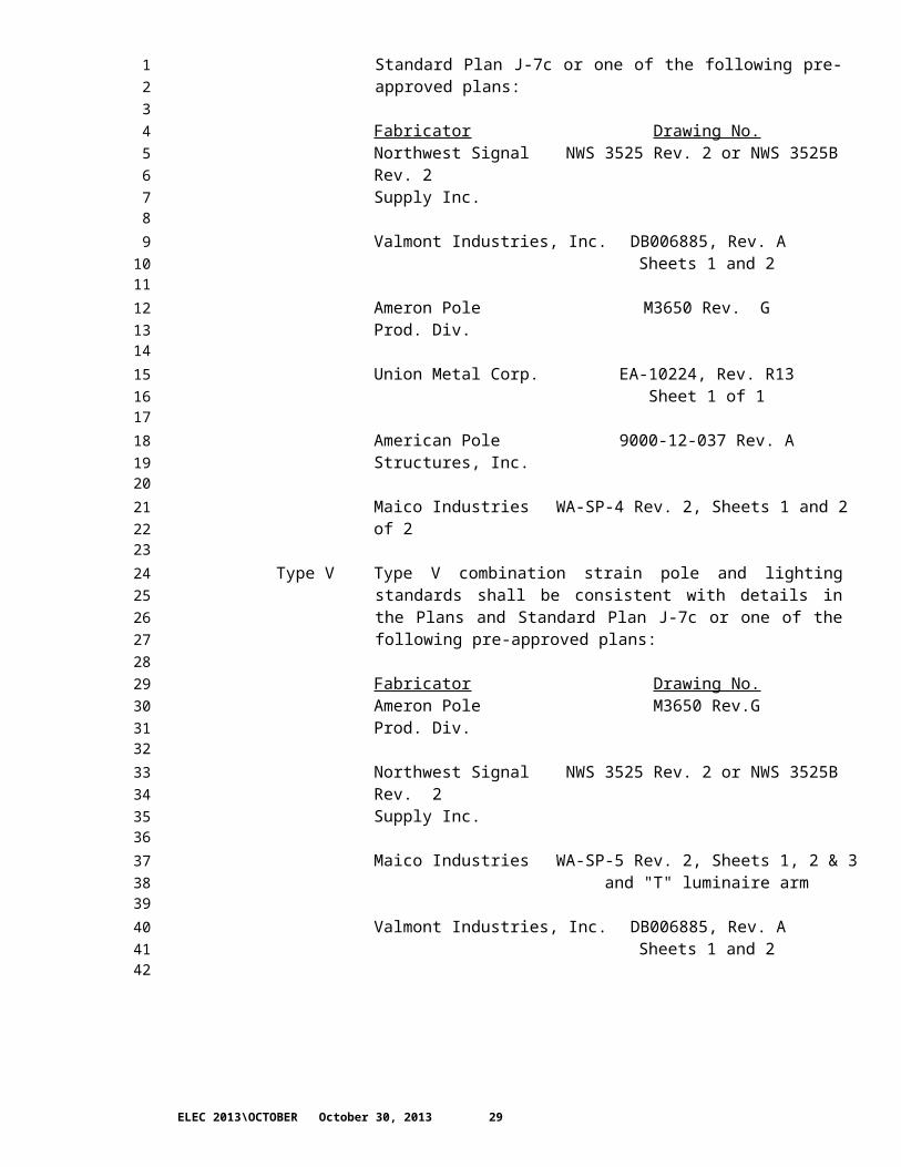
Type V Type V combination strain pole and lighting standards shall be consistent with details in the plans and Standard Plan J-7c or one of the following pre-approved plans:
Fabricator Drawing No.Northwest Signal NWS 3520 Rev. 2 or NWS 3520B Rev. 2Supply Inc.
Valmont Industries, Inc. DB006885, Rev. ASheets 1 and 2
Ameron Pole M3650 Rev. GProd. Div.
Union Metal Corp. EA-10225, Rev. R13Shts. 1 & 2
American Pole 9020-12-007 Rev. BStructures, Inc.
Maico Industries WA-SP-5 Rev. 2 , Sheets 1, 2 & 3and "J" luminaire arm
The luminaire arm shall be Type 1, 16 foot maximum and the luminaire mounting height shall be 40 feet or 50 feet as noted in the plans.
Type SD Type SD standards require special design. All special design shall be based on the latest AASHTO Standard Specifications for Structural Supports for Highway Signs, Luminaires and Traffic Signals and pre-approved plans and as follows:
1. A 90 mph wind loading shall be used.
2. The Design Life and Recurrence Interval shall be 50 years for luminaire support structures.
3. Fatigue design shall conform to AASHTO Section 11, Table 11-1 using fatigue category III.
Complete calculations for structural design, including anchor bolt details, shall be prepared by a Professional Engineer, licensed under Title 18 RCW, State of Washington, in the branch of Civil or Structural Engineering or by an individual holding valid registration in another state as a civil or structural Engineer.
All shop drawings and the cover page of all calculation submittals shall carry the Professional Engineer's original signature, date of
ELEC 2013\OCTOBER October 30, 2013 16
12345678910111213141516171819202122232425262728293031323334353637383940414243444546474849505152

signature, original seal, registration number, and date of expiration. The cover page shall include the contract number, contract title, and sequential index to calculation page numbers. Two copies of the associated design calculations shall be submitted for approval along with shop drawings.
Details for handholes and luminaire arm connections are available from the Bridges and Structures Office.
Foundations for various types of standards shall be as follows:
Type PPB As noted on Standard Plan J-20.10.Type PS As noted on Standard Plan J-21.10-02Type I As noted on Standard Plan J-21.10-02Type FB As noted on Standard Plan J-21.10-02Type RM As noted on Standard Plan J-21.10-02Type CCTV As noted on Standard Plan J-29.15-00Type II As noted in the Plans.Type III As noted in the Plans.Type IV As noted in the Plans and Standard Plan J-7c.Type V As noted in the Plans and Standard Plan J-7c.Type SD As noted in the Plans.
8-20.2(9-29.6).OPT6.GR8(April 1, 2013)Traffic Signal StandardsTraffic signal standards shall be furnished and installed in accordance with the methods and materials noted in the applicable Standard Plans, pre-approved plans, or special design plans.
All welds shall comply with the latest AASHTO Standard Specifications for Structural Supports for Highway Signs, Luminaires and Traffic Signals. Welding inspection shall comply with Section 6-03.3(25)A Welding Inspection.
Hardened washers shall be used with all signal arm connecting bolts instead of lockwashers. All signal arm ASTM A 325 connecting bolts tightening shall comply with Section 6-03-3(33).
Traffic signal standard types and applicable characteristics are as follows:
Type PPB Pedestrian push button posts shall conform to Standard Plan J-20.10 or to one of the following pre-approved plans:
Fabricator Drawing No.Northwest Signal NWS 3540 Rev. 2 andSupply Inc. NWS 3540B Rev. 2
Valmont Ind. Inc. DB00655 Rev. JSheets 1, 2 and 3
Ameron Pole WA10TR-1 & WAPPBPBAProd. Div.
ELEC 2013\OCTOBER October 30, 2013 17
12345678910111213141516171819202122232425262728293031323334353637383940414243444546474849505152

Union Metal Corp. TA-10035 Rev. R6Sht. 1
West CoastEngineering Group WSDOT-PP-01 Rev. 1
KW Industries 10-200-PED-1Rev. 7, Sheets 1, 2 and 3
Type PS Pedestrian signal standards shall conform to Standard Plan J-20.16 or to one of the following pre-approved plans:
Fabricator Drawing No.Northwest Signal NWS 3540 Rev. 2 andSupply Inc. NWS 3540B Rev. 2
Valmont Ind. Inc. DB00655 Rev. JSht. 1 2 & 3
Ameron Pole WA10TR-1 & WA10TR-2Prod. Div.
Union Metal Corp. TA-10025, Rev. R17Sht. 1 & 2
West CoastEngineering Group WSDOT-PP-02 Rev. 1
American Pole WS-PP-03 Rev. 1DStructures, Inc.
KW Industries 10-200-PED-1Rev. 7, Sheets 1, 2 and 3
Type I Type I vehicle signal standards shall conform to Standard Plan J-21.15 or to one of the following pre-approved plans:
Fabricator Drawing No.Northwest Signal NWS 3540 Rev. 2 andSupply Inc. NWS 3540B Rev. 2
Valmont Ind. Inc. DB00655 Rev. JSht. 1 2 & 3
Ameron Pole WA10TR-1 & WA10TR-2Prod. Div.
Union Metal Corp. TA-10025 Rev. R17Sht. 1 & 2
West Coast
ELEC 2013\OCTOBER October 30, 2013 18
12345678910111213141516171819202122232425262728293031323334353637383940414243444546474849505152

Engineering Group WSDOT-PP-02 Rev. 1
American Pole WS-PP-03 Rev. 1D Structures, Inc.
KW Industries 10-200-PED-1Rev. 7, Sheets 1, 2 and 3
Type FB Type FB flashing beacon standard shall conform to Standard Plan J-21.16 or the following pre-approved plan:
Fabricator Drawing No.Valmont Ind. Inc. DB00655 Rev. J
Sht. 1 2 & 3
Union Metal Corp. 50200-B58 Rev. R6Sht 1 & 2
Ameron Pole WA10TR-1 & WA10TR-2Prod. Div.
Northwest Signal NWS 3540 Rev. 2 andSupply Inc. NWS 3540B Rev. 2
KW Industries 10-200-PED-1Rev. 7, Sheets 1, 2 and 3
Type RM Type RM ramp meter standard shall conform to Standard Plan J-22.15 or the following pre-approved plan:
Fabricator Drawing No.Valmont Ind. Inc. DB00655 Rev. J
Sht. 1 2 & 3
Union Metal Corp. 50200-B58 Rev. R6Sht. 1 & 2
Ameron Pole WA10TR-1 & WA10TR-2Prod. Div.
Northwest Signal NWS 3540 Rev. 2 andSupply Inc. NWS 3540B Rev. 2
KW Industries 10-200-PED-1Rev. 7, Sheets 1, 2 and 3
Type CCTV Type CCTV camera pole standards shall conform to one of the following pre-approved Plans:
Fabricator Drawing No.Valmont Industries, Inc. DB 00759 Rev. J
ELEC 2013\OCTOBER October 30, 2013 19
12345678910111213141516171819202122232425262728293031323334353637383940414243444546474849505152

Ameron Pole Product Div. W6CCTV1 Rev. F &W6CCTV2 Rev A
West Coast Engineering Group AP-WSDOT-CP-01 Rev. 3
American Pole Structures, LLC WS-CP-01 Rev. 1CSht. 1 & 2
Union Metal Corporation Drawing No. P33-B318, R11.1,Sheets 1, 2 of 2
Union Metal Corporation Drawing No. P33-B323, Rev. 3Sheets 1, 2 of 2
KW Industries Drawing No. 10-200-CAM-1Rev. 6, Sheets 1 and 2
Northwest Signal Supply, Inc. Drawing No. NWS 3545 (For Type CCTV) Rev. 1
Type II Characteristics:
Luminaire mounting height N.A.Luminaire arms N.A.Luminaire arm length N.A.Signal arms One Only
Type II standards shall conform to one of the following pre-approved plans, provided all other requirements noted herein have been satisfied. Maximum (x) (y) (z) signal arm loadings in cubic feet are noted after fabricator.
Signal ArmLength (max) Fabricator-(x) (y) (z) Drawing No.
65 ft. Valmont Ind. Inc.-(2894) DB00625-Rev.R Shts. 1, 2. 3& 4
65 ft. Union Metal Corp. (2900) 71026-B86 Rev. R10.1Shts. 1, 2 & 3 of 3
65 ft. Ameron Pole-(2900) W3724-1 Rev.J & W3724-2 Rev. G
65 ft. Northwest Signal-(2802) NWS 3505 Rev. 4Supply Inc. or NWS 3505B
Rev. 4
45 ft. American Pole (1875) WS-T2-L Rev.8Structures, Inc. Sheet 1 & 2 of 2
65 ft. American Pole (2913) WS-T2-H Rev. 8Structures, Inc. Sheet 1 & 2 of 2
65 ft. KW Industries 10-200-TSP-4 Rev. 5,
ELEC 2013\OCTOBER October 30, 2013 20
12345678910111213141516171819202122232425262728293031323334353637383940414243444546474849505152

Sheets 1, 2, and 3
65 ft West Coast WSDOT-TS-01 Rev. 3Engineering Group Sheets 1, 2, and 3
65 ft. Maico WSDOTMA Rev. 3Industries (2894) Sheets 1, 2 and 3
Type III Characteristics:
Luminaire mounting height 30 ft., 35 ft.,40 ft., or 50 ft.
Luminaire arms One OnlyLuminaire arm type Type 2Luminaire arm length (max.) 16 ft.Signal arms One Only
Type III standards shall conform to one of the following pre-approved plans, provided all other requirements noted herein have been satisfied. Maximum (x) (y) (z) signal arm loadings in cubic feet are noted after fabricator.
Signal ArmLength (max) Fabricator-(x) (y) (z) Drawing No.
45 ft. American Pole (1875) WS-T3J-L, Rev. 11Structures, Inc. Sheets 1 & 2 of 2
65 ft. Valmont Ind. Inc.-(2947) DB00625-Rev. R, Shts. 1, 2, 3 & 4
and "T" luminaire arm
65 ft. Northwest Signal-(2802) NWS 3505 Rev. 4 orSupply Inc. NWS 3505B Rev. 4
65 ft. Ameron Pole-(2900) W3724-1 Rev. J &Prod. Div. W3724-2 Rev. G
and "T" luminaire arm
65 ft West Coast WSDOT-TS-01 Rev. 3Engineering Group Sht.1, 2.& 3
65 ft. Maico WSDOTMA Rev. 3Industries (2947) Sheets 1, 2 and 3
and "T" luminaire arm
65 ft. KW Industries 10-200-TSP-3 Rev. 5,Sheets 1, 2, and 3
65ft Union Metal Corp. 71026-B87 R11Sheets 1, 2, and 3
ELEC 2013\OCTOBER October 30, 2013 21
12345678910111213141516171819202122232425262728293031323334353637383940414243444546474849505152

65 ft. American Pole (2913) WS-T3J-H, Rev. 10Structures, Inc. Sheets 1 & 2 of 2
Type IV Type IV strain pole standards shall be consistent with details in the Plans and Standard Plan J-7c or one of the following pre-approved plans:
Fabricator Drawing No.Northwest Signal NWS 3525 Rev. 2 or NWS 3525B Rev. 2Supply Inc.
Valmont Industries, Inc. DB006885, Rev. ASheets 1 and 2
Ameron Pole M3650 Rev. GProd. Div.
Union Metal Corp. EA-10224, Rev. R13Sheet 1 of 1
American Pole 9000-12-037 Rev. AStructures, Inc.
Maico Industries WA-SP-4 Rev. 2, Sheets 1 and 2 of 2
Type V Type V combination strain pole and lighting standards shall be consistent with details in the Plans and Standard Plan J-7c or one of the following pre-approved plans:
Fabricator Drawing No.Ameron Pole M3650 Rev.GProd. Div.
Northwest Signal NWS 3525 Rev. 2 or NWS 3525B Rev. 2Supply Inc.
Maico Industries WA-SP-5 Rev. 2, Sheets 1, 2 & 3and "T" luminaire arm
Valmont Industries, Inc. DB006885, Rev. ASheets 1 and 2
The luminaire arm shall be Type 2, 16 foot maximum and the luminaire mounting height shall be 40 feet or 50 feet as noted in the Plans.
Type SD Type SD standards require special design. All special design shall be based on the latest AASHTO Standard Specifications for Structural Supports for Highway Signs, Luminaires and Traffic Signals and pre-approved plans and as follows:
1. A 90 mph wind loading shall be used.
ELEC 2013\OCTOBER October 30, 2013 22
12345678910111213141516171819202122232425262728293031323334353637383940414243444546474849505152

2. The Design Life and Recurrence Interval shall be 50 years for luminaire support structures.
3. Fatigue design shall conform to AASHTO Section 11, Table 11-1 using fatigue category III.
Complete calculations for structural design, including anchor bolt details, shall be prepared by a Professional Engineer, licensed under Title 18 RCW, State of Washington, in the branch of Civil or Structural Engineering or by an individual holding valid registration in another state as a civil or structural Engineer.
All shop drawings and the cover page of all calculation submittals shall carry the Professional Engineer's original signature, date of signature, original seal, registration number, and date of expiration. The cover page shall include the contract number, contract title, and sequential index to calculation page numbers. Two copies of the associated design calculations shall be submitted for approval along with shop drawings.
Details for handholes and luminaire arm connections are available from the Bridges and Structures Office.
Foundations for various types of standards shall be as follows:
Type PPB As noted on Standard Plan J-20.10.Type PS As noted on Standard Plan J-21.10-02Type I As noted on Standard Plan J-21.10-02Type FB As noted on Standard Plan J-21.10-02Type RM As noted on Standard Plan J-21.10-02Type CCTV As noted on Standard Plan J-29.15-00Type II As noted in the Plans.Type III As noted in the Plans.Type IV As noted in the Plans and Standard Plan J-7c.Type V As noted in the Plans and Standard Plan J-7c.Type SD As noted in the Plans.
8-20.2(9-29.6(1)).ESP.DT1Steel Light and Signal Standards
8-20.2(9-29.6(1)).INST1.ESP.DT1Section 9-29.6(1) is supplemented with the following:
8-20.2(9-29.6(1)).OPT1.ESP.DT1(NWR May 1, 2006)Light and Signal Standard PaintingGalvanized steel light and signal standards shall not be painted.
8-20.2(9-29.10).ESP.DT1Luminaires
ELEC 2013\OCTOBER October 30, 2013 23
12345678910111213141516171819202122232425262728293031323334353637383940414243444546474849505152

8-20.2(9-29.10(3)).ESP.DT1High Mast Luminaire Fixtures
8-20.2(9-29.10(3)).INST1.ESP.DT1Section 9-29.10(3) title is revised to read as follows;
8-20.2(9-29.10(3)).OPT1.ESP.DT1(NWR January 21, 2011)Type V Fixture for High Mast Light StandardsType V fixtures for high mast light (HML) standards shall be of the same manufacturer and external appearance, and shall be compatible with the lowering system and associated HML standard called for in these Special Provisions.
Fixtures shall be flat glass lens or open bottom as indicated in the Plans.
Flat glass lens fixtures shall be one of the following:
General Electric HMAA=40 S 5 G 1 F MC5 FHolophane HMAO-4ORHP-48-S-7-PS-FD2Metrolux VA25-V-HPS400-480-CC-FG-MR-FDD
Open bottom fixtures shall be one of the following:
General Electric HMAA=40 S 5 G 1 N MC5 F Holophane HMAO-4ORHP-48-S-7-PS-FD2Metrolux VA25-V-HPS400-480-CC-OBR-MR-FDD
The fixture housing shall be fabricated from aluminum. The entire exterior of the fixture including the ballast/slip fitter mount and the reflector housing shall be finished with a powder coated polyurethane low luster finish matching Federal Standard 595B color chip *** $$1$$ ***. The housing shall withstand a 1000-hour salt spray test as specified in ASTM B 117.
8-20.2(9-29.10(3)).INST2.ESP.DT1Section 9-29.10(3) is supplemented with the following;
8-20.2(9-29.10(3)).OPT1.ESP.DT1(NWR January 21, 2011)Type V Fixture for High Mast Light StandardsType V fixtures for high mast light (HML) standards shall be of the same manufacturer and external appearance, and shall be compatible with the lowering system and associated HML standard called for in these Special Provisions.
Fixtures shall be flat glass lens or open bottom as indicated in the Plans.
Flat glass lens fixtures shall be one of the following:
General Electric HMAA=40 S 5 G 1 F MC5 FHolophane HMAO-4ORHP-48-S-7-PS-FD2
ELEC 2013\OCTOBER October 30, 2013 24
12345678910111213141516171819202122232425262728293031323334353637383940414243444546474849505152

Metrolux VA25-V-HPS400-480-CC-FG-MR-FDD
Open bottom fixtures shall be one of the following:
General Electric HMAA=40 S 5 G 1 N MC5 F Holophane HMAO-4ORHP-48-S-7-PS-FD2Metrolux VA25-V-HPS400-480-CC-OBR-MR-FDD
The fixture housing shall be fabricated from aluminum. The entire exterior of the fixture including the ballast/slip fitter mount and the reflector housing shall be finished with a powder coated polyurethane low luster finish matching Federal Standard 595B color chip *** $$1$$ ***. The housing shall withstand a 1000-hour salt spray test as specified in ASTM B 117.
8-20.2(9-29.10(4)).ESP.DT1Underdeck and Wall Mount Luminaires
8-20.2(9-29.10(4)).INST1.ESP.DT1Section 9-29.10(4) is supplemented with the following:
8-20.2(9-29.10(4)).OPT1.ESP.DT1(NWR May 1, 2006)
Underdeck Fixtures Underdeck fixtures shall be wall mountable and shall be hose-down rated with a gasket between the doorframe and ballast housings and between the doorframe and lens. Housing shall be low copper alloy cast aluminum with gray paint finish. The luminaires down light efficiency shall be no less than 64% of lamp output, with peak candle power occurring at 65 to 70 degrees, using a heavy borosilicate prismatic glass lens with 180 degree beam spread. Lamps shall have HPF ballasts, per requirements of Section 9-29.9. Lamps shall be high-pressure sodium, with mogul base socket. Lens shall be vandal resistant. The luminaires shall have wire protective guards on the lenses. Fusing shall be provided for all conductors above ground potential.
8-20.2(9-29.12).ESP.DT1Electrical Splice Materials
8-20.2(9-29.12).INST1.ESP.DT1Section 9-29.12 is supplemented with the following:
8-20.2(9-29.12).OPT1.ESP.DT1(NWR April 19, 1995)Aerial Splice EnclosuresAerial splice enclosures shall meet the requirements of REA specification PE-52 and GTE Automatic Electric Specification GTS-8514. Aerial splice enclosures shall be re-enterable and resealable without requiring special tools or equipment. Conductor connections shall be sealed, moisture resistant telephone type connectors approved for outside use. The cable shields shall be bonded using an approved low resistance shield connector.
ELEC 2013\OCTOBER October 30, 2013 25
1234567891011121314151617181920212223242526272829303132333435363738394041424344454647484950

8-20.2(9-29.12(2)).ESP.DT1Traffic Signal Splice Material
8-20.2(9-29.12(2)).INST1.ESP.DT1Section 9-29.12(2) is supplemented with the following:
8-20.2(9-29.12(2)).OPT1.ESP.DT1(NWR March 1, 2011)Induction loop splices shall be either the heat shrink type or the re-enterable type with end cap seals.
8-20.2(9-29.13(3)).ESP.DT1Traffic Signal Controller
8-20.2(9-29.13(3)).INST1.ESP.DT1Section 9-29.13(3) is supplemented with the following:
8-20.2(9-29.13(3)).OPT1.ESP.FT1(NWR March 13, 1995)Signal Controller*** $$1$$ *** control equipment shall be used in this contract.
8-20.2(9-29.13(3)).OPT2.ESP.DT1(NWR July 22, 1999)ControllersThe local signal control unit shall be a fully actuated, eight-phase controller. Pedestrian functions on a minimum of four phases shall be provided.
The following functions shall also be provided in the local signal control unit:
1. Guaranteed YellowThe Yellow interval for all phases shall be 3.5 seconds unless the operator sets a higher value for it.
2. Simultaneous Gap OutTwo concurrently timing phases shall simultaneously reach a rest state prior to their termination by gap out and prior to advancing across the barrier. A phase in dual ring operation may re-time its gap from a rest state upon vehicle actuation.
8-20.2(9-29.13).ESP.DT1Controller Cabinet Assemblies
8-20.2(9-29.13(6)).ESP.DT1Emergency Preemption
8-20.2(9-29.13(6)).INST1.ESP.DT1Section 9-29.13(6) is supplemented with the following:
ELEC 2013\OCTOBER October 30, 2013 26
12345678910111213141516171819202122232425262728293031323334353637383940414243444546474849

8-20.2(9-29.13(6)).OPT1.ESP.DT1(NWR May 1, 2006)Emergency Preemption Logic - NEMAThe traffic signal controller shall have the capability of preempting normal traffic signal operation.
The preemption logic shall be an internal software function of the traffic signal controller.
The preemption system shall include the additional functions:
When a preemption call is registered for the phase or phases the controller is presently serving, the controller shall remain in that phase until this call is dropped.
During any preemption phase, “Don’t Walk" or "Hand Symbol" shall be displayed on all pedestrian heads.
8-20.2(9-29.13(6)).OPT2.ESP.DT1(NWR August 10, 2009)Preemption:The system shall be capable of preempting the controller to the phases shown in the Plans when a signal is received from the field detector.
Pre-emption equipment shall be either Opticom or Tomar.
OpticomIf Opticom pre-emption equipment is used, the Contractor shall furnish and install the following:
1. Pre-emption detectors shall be Opticom Model 711.
2. Discriminators shall be four-channel model 454 units. One is required at each controller.
In addition, where auxiliary Opticom pre-emption is used, the Contractor shall furnish and install the following:
3. A 757 auxiliary optical detector wiring harness where more than one detector is called for per channel.
4. A twelve position terminal block of the barrier type rated for 20A at 600 volts RMS minimum and meeting the requirements of Chapter 11 of the Type 170 Hardware Specification, FHWA IP-78-16 as currently amended.
TomarTomar equipment is allowed provided that it is able to receive and respond to Opticom emitter signals.
If Tomar equipment is used, the Contractor shall furnish and install the following:
ELEC 2013\OCTOBER October 30, 2013 27
12345678910111213141516171819202122232425262728293031323334353637383940414243444546474849505152

1. Pre-emption detectors shall be Tomar Model 2091-SD complete with mount and mounting hardware.
2. Discriminators shall be Tomar Model 3080 four-channel units. One is required per controller.
3. The Contractor shall make all initial range adjustments.
4. The pre-emption function operation tests shall be performed using an Opticom emitter.
8-20.2(9-29.13(6)).OPT3.ESP.DT1(NWR November 16, 1995)Emergency Preemption Hardwire:Emergency preemption hardwire equipment installed by this contract shall activate the Emergency Preemption Logic in the traffic signal controller when a signal is received from a dry contact closure.
The contact closure shall be activated by a 120-volt input that is isolated from all controller circuitry.
The equipment used to provide the contact closure shall be housed in a separate enclosure located within the controller cabinet.
8-20.2(9-29.13(10)).ESP.DT1NEMA, Type 170E, 2070 Controllers and Cabinets
8-20.2(9-29.13(10)A).ESP.DT1Auxiliary Equipment for NEMA Controllers
8-20.2(9-29.13(10)A).INST1.ESP.DT1Section 9-29.13(10)A is supplemented with the following:
8-20.2(9-29.13(10)A).OPT1.ESP.DT1(NWR June 24, 2013)NEMA Traffic Actuated ControllersThe cabinet(s) shall contain the following accessories and auxiliary equipment:
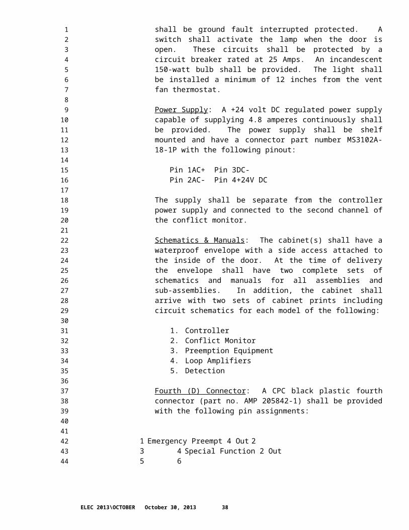
Convenience Outlet & Lamp Socket: Two convenience outlets and a lamp socket shall be furnished in the cabinet(s). The outlets shall be mounted one on each side of the cabinet, near the top shelf, not on the door. The outlet mounted on the right side shall be ground fault interrupted protected. A switch shall activate the lamp when the door is open. These circuits shall be protected by a circuit breaker rated at 25 Amps. An incandescent 150-watt bulb shall be provided. The light shall be installed a minimum of 12 inches from the vent fan thermostat.
Power Supply: A +24 volt DC regulated power supply capable of supplying 4.8 amperes continuously shall be provided. The power
ELEC 2013\OCTOBER October 30, 2013 28
12345678910111213141516171819202122232425262728293031323334353637383940414243444546474849505152
supply shall be shelf mounted and have a connector part number MS3102A-18-1P with the following pinout:
Pin 1 AC+ Pin 3 DC-Pin 2 AC- Pin 4 +24V DC
The supply shall be separate from the controller power supply and connected to the second channel of the conflict monitor.
Schematics & Manuals: The cabinet(s) shall have a waterproof envelope with a side access attached to the inside of the door. At the time of delivery the envelope shall have two complete sets of schematics and manuals for all assemblies and sub-assemblies. In addition, the cabinet shall arrive with two sets of cabinet prints including circuit schematics for each model of the following:
1. Controller2. Conflict Monitor3. Preemption Equipment4. Loop Amplifiers5. Detection
Fourth (D) Connector: A CPC black plastic fourth connector (part no. AMP 205842-1) shall be provided with the following pin assignments:
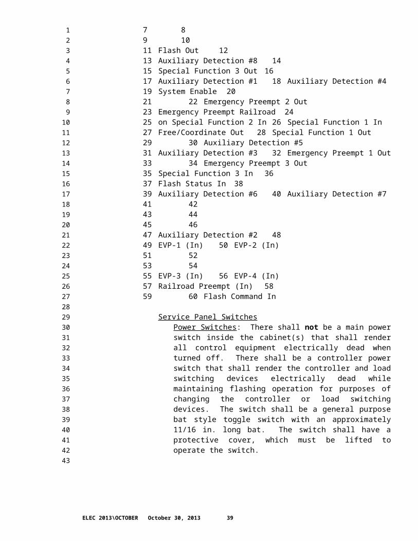
1 Emergency Preempt 4 Out 23 4 Special Function 2 Out5 67 89 1011 Flash Out 1213 Auxiliary Detection #8 1415 Special Function 3 Out 1617 Auxiliary Detection #1 18 Auxiliary Detection #419 System Enable 2021 22 Emergency Preempt 2 Out23 Emergency Preempt Railroad 2425 on Special Function 2 In 26 Special Function 1 In27 Free/Coordinate Out 28 Special Function 1 Out29 30 Auxiliary Detection #531 Auxiliary Detection #3 32 Emergency Preempt 1 Out33 34 Emergency Preempt 3 Out35 Special Function 3 In 3637 Flash Status In 3839 Auxiliary Detection #6 40 Auxiliary Detection #741 4243 4445 4647 Auxiliary Detection #2 4849 EVP-1 (In) 50 EVP-2 (In)51 52
ELEC 2013\OCTOBER October 30, 2013 29
12345678910111213141516171819202122232425262728293031323334353637383940414243444546474849505152

53 5455 EVP-3 (In) 56 EVP-4 (In)57 Railroad Preempt (In) 5859 60 Flash Command In
Service Panel SwitchesPower Switches: There shall not be a main power switch inside the cabinet(s) that shall render all control equipment electrically dead when turned off. There shall be a controller power switch that shall render the controller and load switching devices electrically dead while maintaining flashing operation for purposes of changing the controller or load switching devices. The switch shall be a general purpose bat style toggle switch with an approximately 11/16 in. long bat. The switch shall have a protective cover, which must be lifted to operate the switch.
Stop Time Switch: There shall be a 3 position switch located inside the cabinet door identified as the Stop Time switch. Its positions shall be labeled "Normal" (up), "Off" (center), and "On" (down). With the switch in its Normal position, a stop timing command may be applied to the controller by the police flash switch or the conflict monitor unit. When the switch is in its “Off” position, stop timing commands shall be removed from the controller. The “On” position of the switch shall cause the controller to stop timing. The switch shall be a general purpose bat style toggle switch with an approximately 11/16 in. long bat. The switch shall have a protective cover, which must be lifted to operate the switch.
Detector Disconnect/Test Switches: All eight controller phase inputs shall have disconnect/test switches. Pedestrian detection shall have disconnect/test switches by phase. These switches shall be located inside the cabinet door and labeled by associated phase number. The 3 positions of the switches shall be labeled "Normal" (up) which shall connect the controller to its detector output; "Off" (Center) which shall isolate the controller detection input; and "Test" (down) which shall provide a momentary logic ground to the controller detection input. A see-through Plexiglas cover shall cover all detector disconnect/test switches.
Pedestrian Detector Field Wiring: All pedestrian detectors shall be connected between logic ground and their appropriate field terminal. The terminals shall be grouped together and located in the lower left side panel.
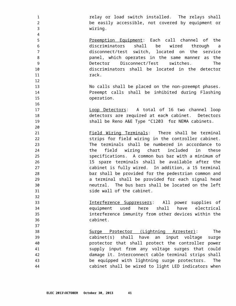
Cabinet Relays: All mechanical relays shall be commonly available from more than one manufacturer and have 24 Volt DC or 120 Volt AC relay coils. Every socket, which has the capacity of accepting a relay or load switch, shall have the appropriate relay or load switch installed. The relays shall be easily accessible, not covered by equipment or wiring.
ELEC 2013\OCTOBER October 30, 2013 30
12345678910111213141516171819202122232425262728293031323334353637383940414243444546474849505152

Preemption Equipment: Each call channel of the discriminators shall be wired through a disconnect/test switch, located on the service panel, which operates in the same manner as the Detector Disconnect/Test switches. The discriminators shall be located in the detector rack.
No calls shall be placed on the non-preempt phases. Preempt calls shall be inhibited during Flashing operation.
Loop Detectors: A total of 16 two channel loop detectors are required at each cabinet. Detectors shall be Reno A&E Type “C1203” for NEMA cabinets.
Field Wiring Terminals: There shall be terminal strips for field wiring in the controller cabinet. The terminals shall be numbered in accordance to the field wiring chart included in these specifications. A common bus bar with a minimum of 15 spare terminals shall be available after the cabinet is fully wired. In addition, a 15 terminal bar shall be provided for the pedestrian common and a terminal shall be provided for each signal head neutral. The bus bars shall be located on the left side wall of the cabinet.
Interference Suppressers: All power supplies of equipment used here shall have electrical interference immunity from other devices within the cabinet.
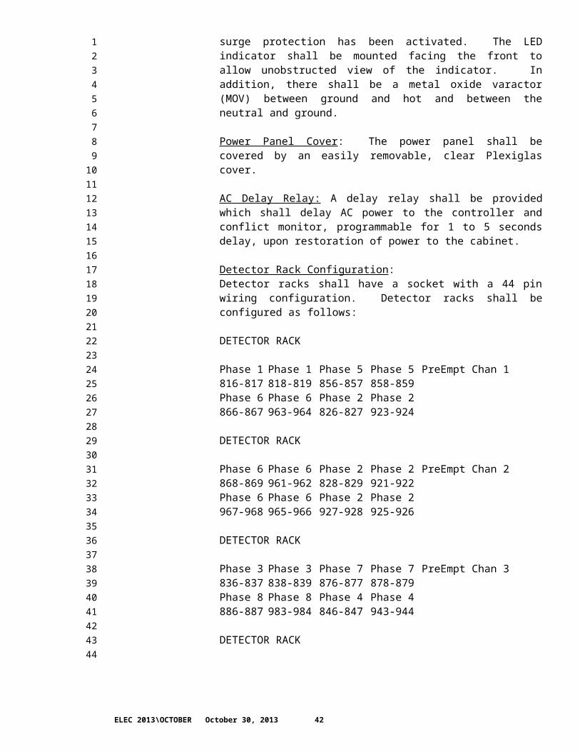
Surge Protector (Lightning Arrester): The cabinet(s) shall have an input voltage surge protector that shall protect the controller power supply input from any voltage surges that could damage it. Interconnect cable terminal strips shall be equipped with lightning surge protectors. The cabinet shall be wired to light LED indicators when surge protection has been activated. The LED indicator shall be mounted facing the front to allow unobstructed view of the indicator. In addition, there shall be a metal oxide varactor (MOV) between ground and hot and between the neutral and ground.
Power Panel Cover: The power panel shall be covered by an easily removable, clear Plexiglas cover.
AC Delay Relay: A delay relay shall be provided which shall delay AC power to the controller and conflict monitor, programmable for 1 to 5 seconds delay, upon restoration of power to the cabinet.
Detector Rack Configuration: Detector racks shall have a socket with a 44 pin wiring configuration. Detector racks shall be configured as follows:
DETECTOR RACK
Phase 1 Phase 1 Phase 5 Phase 5 PreEmpt Chan 1816-817 818-819 856-857 858-859
ELEC 2013\OCTOBER October 30, 2013 31
12345678910111213141516171819202122232425262728293031323334353637383940414243444546474849505152

Phase 6 Phase 6 Phase 2 Phase 2866-867 963-964 826-827 923-924
DETECTOR RACK
Phase 6 Phase 6 Phase 2 Phase 2 PreEmpt Chan 2868-869 961-962 828-829 921-922Phase 6 Phase 6 Phase 2 Phase 2967-968 965-966 927-928 925-926
DETECTOR RACK
Phase 3 Phase 3 Phase 7 Phase 7 PreEmpt Chan 3836-837 838-839 876-877 878-879Phase 8 Phase 8 Phase 4 Phase 4886-887 983-984 846-847 943-944
DETECTOR RACK
Phase 8 Phase 8 Phase 4 Phase 4 PreEmpt Chan 4888-889 981-982 848-849 941-942Phase 8 Phase 8 Phase 4 Phase 4987-988 985-986 947-948 945-946
All 800 series numbers are connected to the appropriate NEMA phase controller inputs through a service panel detector switch. All 900 series numbers are connected to the appropriate NEMA plus controller auxiliary detector inputs through a service panel detector switch.
8-20.2(9-29.13(10)B).ESP.DT1Auxiliary Equipment for Type 170E, 2070 Assemblies
8-20.2(9-29.13(10)B).INST1.ESP.DT1Section 9-29.13(10)B is supplemented with the following:
8-20.2(9-29.13(10)B).OPT1.ESP.DT1(NWR August 19, 2013)Controller Auxiliary Equipment Traffic signal control equipment to be furnished shall be provided with:
1. Flash Indication Jumper PlugsOne for each vehicle display load switch socket (eight minimum). Provides quick and easy change of indications, either red or yellow, for display during flashing operations.
2. Load SwitchesAll load switches shall be model 200 units equipped with replaceable solid state relay modules. Load switches shall be provided for all phases, not just phases used with the current configuration.
ELEC 2013\OCTOBER October 30, 2013 32
12345678910111213141516171819202122232425262728293031323334353637383940414243444546474849505152
3. Conflict MonitorFor type 170E controllers, the conflict monitor shall be a Model 210N unit. For 2070, 2070 Lite and ITS/ATC controllers the conflict monitor shall be a Model 2010 ECL unit. The conflict monitor shall be capable of supporting the flashing yellow arrow signal head display configuration.
4. Loop Detectors A total of 16 two-channel loop detectors are required at each cabinet. Detectors shall be Reno A & E Type “C1103-SS”.
8-20.2(9-29.13(10)C).ESP.DT1NEMA Controller Cabinets
8-20.2(9-29.13(10)C).INST1.ESP.DT1Section 9-29.13(10)C is supplemented with the following:
8-20.2(9-29.13(10)C).OPT1.ESP.DT1(NWR August 19, 2013)Cabinet ConstructionConstruction shall be of 0.125-inch sheet aluminum (5052 alloy), with mill finish. The cabinet shall not be anodized and the exterior shall not be painted.
A green construction core shall be installed at each core lock.
8-20.2(9-29.13(10)C).OPT2.ESP.DT1(NWR April 28, 1999)Cabinet WiringThe cabinet shall be wired for eight vehicle phases, four pedestrian phases, four overlaps, and use with a modem.
The cabinet shall have a computer shelf 16 inches wide and 12 inches deep centered under the lower shelf.
Where the Plans call for a master controller the cabinet shall be wired for use with the master controller.
8-20.2(9-29.13(10)C).OPT3.ESP.DT1(NWR April 28, 1999)Adaptor BoxThe adaptor box shall be fabricated from .125-inch aluminum (5052 alloy), with mill finish. The cabinet shall not be anodized and the exterior shall not be painted.
The Contractor shall verify foundation and cabinet dimensions and mounting bolt patterns prior to submitting shop drawings for the adaptor box to the Engineer. The shop drawings shall be submitted for approval 10 working days in advance of fabrication.
ELEC 2013\OCTOBER October 30, 2013 33
1234567891011121314151617181920212223242526272829303132333435363738394041424344454647484950
The new controller cabinet, if Contracting Agency-supplied, will be available for bolt pattern verification as identified under the subsection, Contracting Agency-Supplied Materials of this provision.
8-20.2(9-29.13(10)D).ESP.DT1Cabinets for Type 170E and 2070 Controllers
8-20.2(9-29.13(10)D).INST1.ESP.DT1Section 9-29.13(10)D is supplemented with the following:
8-20.2(9-29.13(10)D).OPT1.ESP.DT1(NWR February 11, 2013)Cabinet ConstructionConstruction shall be of 0.125-inch sheet aluminum (5052 alloy), with mill finish.
8-20.2(9-29.13(10)D).OPT2.ESP.DT1(NWR August 19, 2013)Generator Transfer SwitchA Generator Transfer Switch capable of switching power from a utility power source to an external generator power source shall be installed on the same side of the cabinet as the Police Panel and parallel with the Police Panel.
8-20.2(9-29.13(10)D).OPT3.ESP.DT1(NWR September 16, 2002)Adaptor BoxThe adaptor box shall be fabricated from .125-inch aluminum (5052 alloy), with mill finish. The cabinet shall not be anodized and the exterior shall not be painted.
The Contractor shall verify foundation and cabinet dimensions and mounting bolt patterns prior to submitting shop drawings for the adaptor box to the Engineer. The shop drawings shall be submitted for approval 10 working days in advance of fabrication.
The new controller cabinet, if Contracting Agency-supplied, will be available for bolt pattern verification as identified under the subsection Contracting Agency-Supplied Materials of this provision.
8-20.2(9-29.15).ESP.DT1Flashing Beacon Control
8-20.2(9-29.15).INST1.ESP.DT1Section 9-29.15 is supplemented with the following:
8-20.2(9-29.15).OPT1.ESP.DT1(NWR January 23, 2006)Solid State FlasherThe solid state flasher shall provide two output circuits to permit alternate flashing of signal faces. The flash rate shall be 55 flashes per minute 10%. Duty cycle for each circuit shall be 50% on, 50% off 2%.
ELEC 2013\OCTOBER October 30, 2013 34
12345678910111213141516171819202122232425262728293031323334353637383940414243444546474849505152
Each circuit shall be rated at 15 amperes and switching shall occur at the zero crossover point of the AC voltage. The voltage range shall be 95 to 135 volts AC. The nominal voltage shall be 120 volts AC. The operating frequency range shall be 60 Hz 3.0 Hz. The two-circuit solid-state flasher shall be designed to operate as specified at any ambient temperature range from -30°F. to +165°F. (-34.4°C. to +73.8°C).
CabinetThe raintight housing shall be aluminum, conforming to the requirements of Section 9-29.25 and this Special Provision. Cabinet dimensions shall be:
Depth Height Width
6 inches 10 inches 8 inches
The cabinet door shall have two hinges. The hinges shall meet the requirements for the alternate hinge detailed on Standard Plan J-3b. The cabinet door shall be secured with a spring-loaded construction core lock capable of accepting a Best CX series core. A green construction core shall be installed at each core lock. Upon contract completion two master keys for each cabinet shall be delivered to the Engineer. Socket bases for the flasher unit shall be mounted on a circuit board inside the cabinet.
8-20.2(9-29.16).ESP.DT1Vehicular Signal Heads, Displays and Housing
8-20.2(9-29.16).INST1.ESP.DT1Section 9-29.16 is supplemented with the following:
8-20.2(9-29.16).OPT1.ESP.DT1(NWR February 11, 2013)Back PlateBack plates shall be constructed of louvered anodized aluminum.
8-20.2(9-29.16).OPT2.ESP.DT1(NWR March 8, 2000)Fiber Optic Signal HeadA 12-inch fiber optic signal section capable of alternately displaying a yellow arrow and a green arrow shall be furnished and installed where specified in the Plans.
8-20.2(9-29.16(2)).ESP.DT1Conventional Traffic Signal Heads
8-20.2(9-29.16(2)A).ESP.DT1Optical Units
8-20.2(9-29.16(2)A).INST1.ESP.DT1Section 9-29.16(2)A is supplemented with the following:
ELEC 2013\OCTOBER October 30, 2013 35
1234567891011121314151617181920212223242526272829303132333435363738394041424344454647484950
8-20.2(9-29.16(2)A).OPT1.ESP.DT1(NWR March 8, 2004)LED Signal DisplaysAll traffic signal displays shall be the Light Emitting Diode (LED) type and shall be from one of the following manufacturers:
Dialight Corporation1913 Atlantic AvenueManasquan, NJ 08736Telephone: (732) 223-9400Fax: (732) 223-8788
GELcore, LLC6810 Halle DriveValley View, OH 44125Telephone: (216) 606-6555Fax: (216) 606-6556
Precision Solar Controls, Inc.2960 Market StreetGarland, TX 75041Telephone: (972) 278-0553Fax: (972) 271-9583
Each LED signal module shall be designed to be installed in the door frame of a standard traffic signal housing. The lamp socket, reflector holder and lens used with an incandescent lamp shall not be used in a signal section in which a LED signal module is installed. The installation of a LED signal module shall not require any modification to the housing. The LED signal module shall be a single, self-contained device, not requiring onsite assembly for installation into an existing traffic signal housing.
All red and yellow LED signal modules shall be manufactured with a matrix of AllnGaP LED light sources and green LED signal modules shall be manufactured with a matrix of InGaN LED light sources. The LED traffic signal module shall be operationally compatible with controllers and conflict monitors on this project. The LED lamp unit shall contain a disconnect that will show an open switch to the conflict monitor when less than 60% of the LEDs in the unit are operational.
Each LED module shall conform to the current standards in Institute of Transportation Engineers (ITE) VTCSH Part 2 and a Certificate of Compliance with these standards shall be submitted by the manufacturer for each type of signal head. The certificate shall state that the lot of signal heads meets the current ITE specification. A label shall be placed on each LED signal module certifying conformance to this specification. The manufacturer’s name, trademark, serial number and other necessary identification shall be permanently marked on the backside of the LED signal module. LED signal modules used on this project shall be from the same manufacturer. A label shall be provided on the LED housing and the Contractor shall mark the label with a permanent marker to note the installation date.
ELEC 2013\OCTOBER October 30, 2013 36
12345678910111213141516171819202122232425262728293031323334353637383940414243444546474849505152

The manufacturer shall provide a written warranty against defects in materials and workmanship for the LED signal modules for a period of 60 months after the installation of the modules. All warranty documentation shall be given to the Engineer prior to installation.
8-20.2(9-29.16(4)).ESP.DT1Traffic Signal Cover
8-20.2(9-29.16(4)).INST1.ESP.DT1Section 9-29.16(4) is supplemented with the following:
8-20.2(9-29.16(4)).OPT1.ESP.DT1(NWR August 10, 2009)Covering MaterialSignal head covering material shall consist of 4 mil minimum thickness black polyethylene sheeting.
8-20.2(9-29.18).ESP.DT1Vehicle Detector
8-20.2(9-29.18).INST1.ESP.DT1Section 9-29.18 is supplemented with the following:
8-20.2(9-29.18).OPT1.ESP.DT1(NWR August 10, 2009)Loop AmplifierLoop detector amplifiers shall be as follows:
Model: Model C-1103-SS
Manufacturer: Reno A&E4655 Aircentet CircleReno, NV 89502Ph: (775) 826-2020www.renoe.com
8-20.2(9-29.18).OPT2.ESP.DT1(NWR February 11, 2013)Loop SealantLoop sealant for use in HMA pavement shall be one of the following:
1. RAI Pro-Seal 6006EX2. QCM EAS-143. 3M Black 50004. Craftco Inc. Part #34271
Loop sealant for use on concrete bridge decks and PCC pavement shall be one of the following:
1. 3M Black 50002. Gold Label Flex 1P3. QCM EAS-14
ELEC 2013\OCTOBER October 30, 2013 37
12345678910111213141516171819202122232425262728293031323334353637383940414243444546474849505152
8-20.2(9-29.18).OPT3.ESP.DT1(NWR August 10, 2009)Video detectionAll components needed to provide a complete video detection system shall be supplied and installed per manufacturer’s recommendation.
The video detection equipment shall include, but not be limited to, Cameras, Camera Housings, Camera Lens, Camera Mounting Hardware, Video Image Processors, Input File Adapters, lens Adjustment Modules, Keypad and Monitor.
The video detection system shall be capable of supplying video detection to the signal controller phases as indicated in the plans.
The video detection system shall be one of the following:
1. Iteris Vantage EdgeIteris1515 S. Manchester Avenue Anaheim, CA. 92802-2907
2. Traficon VIP3Traficon NVBissegemsestraat 45B-8501 HeuleBelgium, Europe
8-20.2(9-29.18).OPT4.ESP.DT1(NWR July 18, 2005)Preformed LoopsPreformed detector loops shall be factory assembled. Homeruns shall be pre-wired and shall be an integral part of the loop assembly. The loop configurations and homerun lengths shall be assembled for the specific application shown in the Plans.
All materials used to protect the wire in the preformed loop shall have properties that shall withstand the temperature and pressure of paving applications without melting or cracking.
The loop and homerun shall be constructed using synthetic cord reinforced hydraulic flex hose. Hose for the loop and homerun shall each be one piece. The only allowable joints or splices in the hose shall be where the homeruns connect to the loops.
Hose tee connections shall be high temperature synthetic rubber. The tee shall be of proper size to attach directly to the hose to minimize glue joints. The tee shall have the same flex properties as the hose.
The number of turns in the loop shall be as shown in the Plans. Homerun wire pairs shall be twisted a minimum of two turns per foot. No wire splices shall be allowed in the preformed detector loop assembly. The direction of the twist
ELEC 2013\OCTOBER October 30, 2013 38
12345678910111213141516171819202122232425262728293031323334353637383940414243444546474849505152
shall be identified as CW for clockwise and CCW for counter clockwise twist. The loops shall be available to order from the manufacturer with both twist directions available.
The loop and homeruns shall be filled and sealed with a flexible sealant. The sealant, when set up, shall not soften at 180 degrees Fahrenheit, nor get brittle at minus 20 degrees Fahrenheit.
All preformed detector loops shall carry a manufacturer’s warranty stating that the loops will be free from defects in materials and workmanship for a service period of ten (10) years from the date of purchase.
8-20.2(9-29.19).ESP.DT1Pedestrian Push Buttons
8-20.2(9-29.19).INST1.ESP.DT1Section 9-29.19 is supplemented with the following:
8-20.2(9-29.19).OPT1.ESP.DT1(NWR November 4, 2013)APS Pushbutton StationPedestrian pushbutton station equipment shall be from one of the following manufacturers:
Polara Navigator EN4 (4-wire system)Polara Manufacturing9153 Stellar CourtCorona, CA 92883888-340-4872http://www.polara.com/navigator.htmlDistributed by:Advanced Traffic Products909 SE Everett Mall WySuite B280Everett, WA 98208425-347-6208
Novax SoundSafe APSNovax Industries Corporation202-1525 Cliveden AveDelta, BC V3M 6L2604-525-5644http://www.novax.com/#!products/vstc1=soundsafeDistributed by:Northwest Signal Supply12965 SW Herman RdTualatin, OR 97062503-635-4351
Campbell Company Advisor Guide APSCampbell Company
ELEC 2013\OCTOBER October 30, 2013 39
12345678910111213141516171819202122232425262728293031323334353637383940414243444546474849505152

450 W McGregor DrBoise, ID 83705208-345-7459http://www.pedsafety.com/advisor-guide-aps/
No WA distributor listed.
The pushbutton stations and adapters shall be Forest Green in color. The sign shall be 9 inch by 12 inch, option B (MUTCD R10-3b), when used in conjunction with a non-countdown type pedestrian signal display or 9 inch by 15 inch, option G (MUTCD R10-3e), when used in conjunction with a countdown type pedestrian signal display. The sign shall include a frame adapter plate.
A pole adaptor, from the pushbutton station manufacturer, shall be utilized when a pole adaptor is required.
Each pedestrian signal pushbutton station shall include one pedestrian signal head control unit, mountable in the associated pedestrian signal display enclosure.
All manufacturer recommended setup equipment, required to program, adjust and make operational the pedestrian pushbutton stations, shall be furnished with each complete pushbutton system.
All pedestrian pushbutton station equipment shall be the same make or model from one manufacturer.
8-20.2(9-29.20).ESP.DT1Pedestrian Signals
8-20.2(9-29.20).INST1.ESP.DT1Section 9-29.20 is supplemented with the following:
8-20.2(9-29.20).OPT3.ESP.DT1NWR January 26, 2011)Countdown Pedestrian Signal All pedestrian signal displays shall be the countdown type signal display as follows and from the following manufacturer:
Model: 430-6479-001X
Manufacturer: Dialight Corp.1501 Route 34 SouthFarmingdale, NJ 07727http://www.dialight.com/
8-20.2(9-29.24).ESP.DT1Service Cabinets
8-20.2(9-29.24).INST1.ESP.DT1Section 9-29.24 is supplemented with the following:
ELEC 2013\OCTOBER October 30, 2013 40
123456789101112131415161718192021222324252627282930313233343536373839404142434445464748495051
8-20.2(9-29.24).OPT1.ESP.DT1(NWR February 11, 2013)Service Cabinet ConstructionService cabinets shall be fabricated from 0.125 inch sheet aluminum (5052 alloy) with mill finish. The aluminum shall not be anodized and the exterior shall not be painted.
Cabinet doors shall be four-hinged with a two-position door stop assembly and a three point latch.
A three-position terminal block shall be installed between the main electrical service panel and the photocell assembly base.
The cabinet bonding connection shall be a welded plate with stainless steel hardware, Belleville washers, cu/al lug, and antioxidant compound. The bolt shall be torqued to fully compress the Belleville washers.
8-20.2(9-29.24).OPT2.ESP.DT1(NWR August 10, 2009)Uninterruptible Power Supply (UPS)The UPS system shall provide traffic signal system battery backup power in the event of loss or failure of normal utility power. The UPS system shall be constructed for full on line configuration (line interactive type), providing automatic voltage regulation and power conditioning when under normal utility power. The transfer from utility power to battery power and vice versa shall not interfere with the normal operation of the connected traffic signal controller including conflict monitor and any other peripheral devices within the traffic controller assembly.
The completely assembled UPS system, including enclosure, shall be obtained by the Contractor from the following manufacturer:
Alpha Technologies, Inc.3767 Alpha WayBellingham, WA 98226Phone: 360 647 2360Email: [email protected]://www.alpha.com
The UPS system shall include the following equipment:
UPS CabinetThe enclosure cabinet shall be a CALTRANS approved Type 332 cabinet with the following:
Items 2, 4 and 5 of the first paragraph of Section 9-29.13(7)E shall be provided with the cabinet. Green construction cores shall be installed for each cabinet core lock.
The cabinet shall be provided with a breaker panel with two 15 amp, 120 volt, single pole breakers, one each for the fan and the lights.
ELEC 2013\OCTOBER October 30, 2013 41
12345678910111213141516171819202122232425262728293031323334353637383940414243444546474849505152
Item M of Section 9-29.13(7)C shall be provided with the cabinet.
Construction shall be of 0.125-inch sheet aluminum (5052 alloy), with mill finish. The aluminum shall not be anodized and the exterior shall not be painted.
A thermostatically controlled cooling fan, with a minimum CFM of three times the cabinet volume shall be installed at the top of the cabinet.
Three battery shelves shall be furnished. Each shelf shall be capable of supporting two Alpha (220 GOLD-HP) batteries. A minimum of two and one half inches of side clearance and six inches of overhead clearance is required for each battery.
A minimum of 12 inches of clearance shall be maintained between the bottom rack and the bottom of the cabinet.
Generator Transfer Switch and EnclosureThe UPS Type 332 cabinet shall include a transfer switch enclosure of identical materials, dimensions and installation methods as the police panel type enclosure identified in the first paragraph of Section 9-29.13(7)E except that the enclosure door shall include a spring loaded construction core lock capable of accepting a Best 6-pin CX series core. The core lock shall be installed with a green construction core. Upon contract completion, two master keys for the construction core shall be delivered to the Engineer. The transfer switch enclosure shall be installed at the same location normally occupied by the police panel enclosure.
The transfer switch enclosure shall contain the following generator transfer switch equipment:
One NEMA L5-30P Flanged Inlet generator connector
One Utility power “ON” indicator light. The indicator light shall be labeled ”Utility”.
One generator power “ON” indicator light. The indicator light shall be labeled “Generator”.
Two 30 amp, 120 volt, single pole, single phase, circuit breakers. One circuit breaker shall be labeled “Generator” and the other circuit breaker shall be labeled “Utility”. Both labels shall be engraved phenolic name plates.
The enclosure shall include a mechanical lock out feature that prevents the Utility circuit breaker and the Generator circuit breaker from being in the ON position at the same time. The circuit breakers shall be capable of being independently switched.
The conductors from the generator transfer switch enclosure to the rack mounted automatic transfer switch shall be enclosed in nylon mesh sleeve.
The enclosure door shall be labeled with the letters “GTS”.
ELEC 2013\OCTOBER October 30, 2013 42
12345678910111213141516171819202122232425262728293031323334353637383940414243444546474849505152

UPS Internal ComponentsThe following equipment shall be furnished and mounted to the EIA rack in the UPS cabinet.
Alpha - #017-201-31 Controller Power Module - FXM 2000 w/SNMP module
Alpha - # 020-168-25 Automatic Transfer Switch (UATS)
Alpha – # 740-755-21 Surge Suppressor Assembly, 120/240VAC
Alpha – # 740-748-23 Receptacle Plate Assembly
The following equipment shall be installed on the battery shelves:
Alpha - # 220 GOLD-HP GXL Battery (Four batteries shall be provided)
Alpha - #012-306-21 Alpha Guard Battery Management System
Alpha - #740-648-27 Battery Cable kit
Maintenance and Operations Manual(s)Two Maintenance and Operations Manuals from Alpha Technologies shall be provided for each UPS cabinet.
8-20.2(1).GR8Equipment List And Drawings
8-20.2(1).INST1.GR8Section 8-20.2(1) is supplemented with the following:
8-20.2(1).OPT1.ESP.DT1(NWR November 13, 1996)Manufacturer's data for materials proposed for use in the contract which require approval shall be submitted in one complete package.
8-20.2(1).OPT2.ESP.DT1(NWR April 19, 1995)Pole base to light source distances (H1) for lighting standards with pre-approved plans shall be as noted in the Plans.
8-20.2(1).OPT3.ESP.DT1(NWR April 19, 1995)Pole base to light source distances (H1) for lighting standards with pre-approved plans will be determined or verified by the Engineer at the request of the Contractor prior to fabrication.
8-20.2(1).OPT4.ESP.DT1(NWR April 19, 1995)Pole base to light source distances (H1) for lighting standards without pre-approved plans will be furnished by the Engineer as part of the final approved shop drawings, prior to fabrication.
ELEC 2013\OCTOBER October 30, 2013 43
12345678910111213141516171819202122232425262728293031323334353637383940414243444546474849505152

8-20.2(1).OPT3.GR8(March 13, 1995)If traffic signal standards, strain pole standards, or combination traffic signal and lighting standards are required, final verified dimensions including pole base to signal mast arm connection point, pole base to light source distances (H1), mast arm length, offset distances to mast arm mounted appurtenances, and orientations of pole mounted appurtenances will be furnished by the Engineer as part of the final approved shop drawings prior to fabrication.
8-20.2(1).OPT5.ESP.DT1(NWR June 6, 1996)If traffic signal standards, strain pole standards, or combination traffic signal and lighting standards are proposed, final verified dimensions including pole base to signal mast arm connection point, pole base to light source distances (H1), mast arm length, offset distances to mast arm mounted appurtenances, and orientations of pole mounted appurtenances will be furnished by the Engineer as part of the final approved shop drawings prior to fabrication.
Final ground and roadway cross sections at the locations of the standards shall be submitted for approval along with the shop drawings.
8-20.3.GR8Construction Requirements
8-20.3(1).GR8General
8-20.3(1).INST1.ESP.DT1Section 8-20.3(1) is supplemented with the following:
8-20.3(1).OPT1.ESP.DT1(NWR February 11, 2013)Fiber Optic Cable InstallationWhen installing new fiber optic cable or reinstalling existing fiber optic cable into new or existing cable vaults or pull boxes, the installation method shall ensure that the cable is free of dirt and debris as it enters the conduit and that no dirt or debris enters the conduit receiving the cable prior to the conduit being plugged or sealed.
When installing fiber optic cable, the installation method shall prevent the fiber cable from direct contact with the ground or pavement between pulls or prior to the installation of the fiber cable into the conduit.
8-20.3(1).OPT2.ESP.DT1(NWR May 15, 2000)Energized EquipmentWork shall be coordinated so that electrical equipment, with the exception of the service cabinet, is energized within 72 hours of installation.
ELEC 2013\OCTOBER October 30, 2013 44
12345678910111213141516171819202122232425262728293031323334353637383940414243444546474849

8-20.3(1).OPT3.ESP.DT1(NWR June 20, 1995)Pole RemovalPoles designated for removal shall not be removed prior to approval of the Engineer.
8-20.3(1).OPT4.ESP.DT1(NWR January 11, 2005)Signal Display InstallationSignal displays shall be installed no more than 30 days prior to scheduled signal turn on or changeover.
8-20.3(1).OPT5.ESP.DT1(NWR October 31, 2005)Construction Core InstallationThe Contractor shall coordinate installation of construction cores with Contracting Agency maintenance staff through the Engineer. The Contractor shall provide written notice to the Engineer, a minimum of seven working days in advance of proposed installation. The Contractor shall advise the Engineer in writing when construction cores are ready to be removed.
8-20.3(1).OPT6.ESP.DT1(NWR May 15, 2000)Electrical Equipment RemovalsRemovals associated with the electrical system shall not be stockpiled within the job site without the Engineer's approval.
8-20.3(1).OPT7.ESP.FT1(NWR February 11, 2013)Contracting Agency Owned EquipmentA portion of the temporary or existing electrical equipment to be removed shall remain the property of the Contracting Agency.
The following shall be disconnected, dismantled, and delivered to the Contracting Agency:
***$$1$$***
Removed electrical equipment which remains the property of the Contracting Agency shall be delivered to:
WSDOT Signal Shop3700 9th Ave. So.Seattle WA 98134Phone: (206) 442-2110
Five days written advance notice shall be delivered to both the Engineer and the Electronic Parts Specialist at the address listed above. Delivery shall occur during the hours of 8:00 a.m. to 2:00 p.m. Monday through Friday. Material will not be accepted without the required advance notice.
ELEC 2013\OCTOBER October 30, 2013 45
123456789101112131415161718192021222324252627282930313233343536373839404142434445464748495051

Equipment damaged during removal or delivery shall be repaired or replaced to the Engineer's satisfaction at no cost to the Contracting Agency.
The Contractor shall be responsible for unloading the equipment where directed by the Engineer at the delivery site.
8-20.3(1).OPT8.ESP.DT1(NWR April 11, 2001)Wire RemovalRemove all wires from salvaged light and signal standards.
8-20.3(1).OPT9.ESP.DT1(NWR September 20, 1995)Controller Cabinet RemovalController cabinets shall not be removed until all associated electronic equipment is removed by Contracting Agency signals personnel. All other equipment shall be removed by the Contractor and delivered within 24 hours following removal to the Contracting Agency.
8-20.3(1).OPT10.ESP.DT1(NWR November 16, 1995)Span Wire RemovalSpan wire shall not be lowered or disconnected from strain poles until all associated signal heads and signs have been removed from the span.
8-20.3(1).OPT11.ESP.DT1(NWR August 5, 1996)Pole Shaft and Mast Arm Identification All removed mast arms and pole shafts shall be identified by paper identification tags recording pole number, intersection location (such as SR XXX, Jct XXX), and mast arm length.
Four inch by six inch (minimum) tags shall be taped to corresponding pole shafts and mast arms. Information on the mast arm tag shall match the information on the corresponding pole shaft tag. Each tag shall be entirely covered with clear acetate tape. The tape shall be wrapped one full circle around the shaft or arm with a 1/2 inch minimum overlap at the ends and sides.
The Contractor shall bundle the complete signal standard assembly together. The assembly consists of pole shaft, mast arm, and connecting bolts. Connecting bolts shall be attached to the original mast arm base plate.
8-20.3(1).OPT12.ESP.DT1(NWR April 11, 2001)Contractor Owned RemovalsAll removals associated with an electrical system, which are not designated to remain the property of the Contracting Agency, shall become the property of the Contractor and shall be removed from the project.
The Contractor shall:
ELEC 2013\OCTOBER October 30, 2013 46
12345678910111213141516171819202122232425262728293031323334353637383940414243444546474849505152

Remove all wires for discontinued circuits from the conduit system.
Remove elbow sections of abandoned conduit entering junction boxes.
Abandoned conduit encountered during excavation shall be removed to the nearest outlets or as directed by the Engineer.
Remove foundations entirely, unless the Plans state otherwise.
Backfill voids created by removal of foundations and junction boxes. Backfilling and compaction shall be performed in accordance with Section 2-09.3(1)E.
8-20.3(1).OPT15.ESP.DT1(NWR May 15, 2000)Surface Mounted AppurtenancesElectrical appurtenances to be surface mounted on structures shall be mounted so that a minimum ¼ inch space is maintained between the appurtenance and structure.
8-20.3(5).GR8Conduit
8-20.3(5)A1.ESP.DT1Fiber Optic Conduit
8-20.3(5)A1.INST1.ESP.DT1Section 8-20.3(5)A1 is supplemented with the following:
8-20.3(5)A1.OPT1.ESP.DT1(NWR June 24, 2013)When multiple conduits are installed in the same trench, one location wire shall be placed between conduits. When multiple conduits are installed in the same boring, one locate wire is required for the conduit bundle.
Location wire routed into pull boxes or cable vaults shall be attached to the “C” channel or the cover hinge bracket with stainless steel bolts and straps. A 1-foot loop of locate wire shall be provided above the channel as shown in the Plans.
8-20.3(5)A2.ESP.DT1ITS and Cabinet Outer and Inner Duct ConduitSection 8-20.3(5)A2 is supplemented with the following:
8-20.3(5)A2.INST1.ESP.DT1Section 8-20.3(5)A2 is supplemented with the following:
ELEC 2013\OCTOBER October 30, 2013 47
1234567891011121314151617181920212223242526272829303132333435363738394041424344454647
8-20.3(5)A2.OPT1.ESP.DT1(NWR June 24, 2013)Conduit SealExisitng conduits, entering cabinets, that are scheduled to have cables added or removed shall be sealed with an approved mechanical plug or waterproof foam at both ends of the conduit run. Existing Outer duct and inner duct conduit, entering cabinets, that are scheduled to have cables added or removed shall be sealed according to this section.
8-20.3(5)E3.ESP.DT1Boring
8-20.3(5)E3.INST1.ESP.DT1Section 8-20.3(5)E3 is supplemented with the following:
8-20.3(5)E3.OPT1.ESP.DT1(NWR October 16, 2006)In addition to the requirements for boring with casing, the Contractor shall submit to the Engineer for approval a pit plan and a proposed method of boring that includes, but is not limited to, the following:
a. A pit plan depicting:
1. Protection of traffic and pedestrians.2. The dimension of the pit.3. Shoring, bracing, struts, walers, or sheet pile4. Type of casing
b. The proposed method of boring, including:
1. The boring system2. The support system3. The support system under and at the bottom of the pit.
The shoring and boring pit plan shall be prepared by and bear the seal and signature of a Washington State licensed Professional Civil Engineer.
Installed casing pipe shall be free from grease, dirt, rust, moisture and any other deleterious contaminants.
Commercial concrete meeting the requirements of Section 6-02.3(2)B may be used to seal the casing.
8-20.3(6).GR8Junction Boxes, Cable Vaults, and Pull boxes
8-20.3(6).INST1.ESP.DT1Section 8-20.3(6) is supplemented with the following:
ELEC 2013\OCTOBER October 30, 2013 48
12345678910111213141516171819202122232425262728293031323334353637383940414243444546474849505152
8-20.3(6).OPT1.ESP.DT1(NWR February 11, 2013)Unless otherwise noted in the Plans or approved by the Engineer, junction boxes, cable vaults and pull boxes shall not be placed within the traveled way or paved shoulders.
All junction boxes, cable vaults, and pull boxes placed within the traveled way or paved shoulders shall be heavy-duty.
Wiring shall not be pulled into any conduit until all associated junction boxes have been adjusted to, or installed in, their final grade and location, unless installation is necessary to maintain system operation. If wire is installed for this reason, sufficient slack shall be left to allow for future adjustment.
Prior to installing new cables or reinstalling existing cables into new or existing cable vaults, pull boxes or junction boxes, the cable vault, pull box or junction box shall be cleaned of all dirt and debris.
When junction boxes, cable vaults and pull boxes are installed or adjusted prior to construction of finished grade, pre-molded joint filler for expansion joints may be placed around the junction boxes, cable vaults and pull boxes. The joint filler shall be removed prior to adjustment to finished grade.
The six-inch gravel pad required in Standard Plan J-40.10.01 and J-40.30.00 shall be maintained. When existing junction boxes do not have this gravel pad, it shall be installed as part of the adjustment to finished grade.
Heavy-duty Type 4, 5 and 6 junction boxes, cable vaults and pull boxes shall be installed in accordance with the following:
1. Excavation for junction boxes, cable vaults and pull boxes shall be sufficient to leave one foot in the clear between their outer surface and the earth bank.
2. Junction boxes, cable vaults and pull boxes shall be installed on a level 6-inch layer of crushed surfacing top course, in accordance with 9-03.9(3), placed on a compacted or undisturbed foundation. The crushed surfacing shall be compacted in accordance with Section 2-09.3(1)E.
3. After installation, the lid/cover shall be kept bolted down during periods when work is not actively in progress at the junction box, cable vault or pull box.
4. Before closing the lid/cover, the lid/cover and the frame/ring shall be thoroughly brushed and cleaned of all debris. There shall be absolutely no visible dirt, sand or other foreign matter between the bearing surfaces.
5. When the lid/cover is closed for the final time, a liberal coating of anti-seize compound shall be applied to the bolts and nuts and the lid shall be securely tightened.
ELEC 2013\OCTOBER October 30, 2013 49
123456789101112131415161718192021222324252627282930313233343536373839404142434445464748495051

6. Hinges on the Type 4, 5 and 6 junction boxes shall be located on the side of the box, which is nearest to adjacent shoulder. Hinges shall allow the lid to open 180 degrees.
8-20.3(8).GR8Wiring
8-20.3(8).INST1.GR8Section 8-20.3(8) is supplemented with the following:
8-20.3(8).OPT1.ESP.DT1(NWR April 14, 2003)Wire LabelsAt each junction box, all illumination wires, power supply wires, and communication cable shall be labeled with a PVC marking sleeve. For illumination and power supply circuits the sleeve shall bear the circuit number. For communication cable the sleeve shall be marked “Comm.”.
8-20.3(8).OPT2.ESP.DT1(NWR March 13, 1995)Wire SplicesAll splices shall be made in the presence of the Engineer.
8-20.3(8).OPT3.ESP.DT1(NWR May 1, 2006)Illumination Circuit SplicesTemporary splices shall be the heat shrink type.
8-20.3(8).OPT1.GR8(March 13, 1995)Field Wiring Chart501 AC+ Input 516-520 Railroad Pre-empt502 AC- Input 5A1-5D5 Emergency Pre-empt503-510 Control-Display 541-580 Coordination511-515 Sign Lights 581-599 Spare
Movement Number 1 2 3 4 5 6 7 8 9
Vehicle HeadRed 611 621 631 641 651 661 671 681 691Yellow 612 622 632 642 652 662 672 682 692Green 613 623 633 643 653 663 673 683 693Spare 614 624 634 644 654 664 674 684 694Spare 615 625 635 645 655 665 675 685 695AC- 616 626 636 646 656 666 676 686 696Red Auxiliary 617 627 637 647 657 667 677 687 697Yellow Auxiliary 618 628 638 648 658 668 678 688 698Green Auxiliary 619 629 639 649 659 669 679 689 699
Pedestrian Heads & Dets.Hand 711 721 731 741 751 761 771 781 791Man 712 722 732 742 752 762 772 782 792AC- 713 723 733 743 753 763 773 783 793
ELEC 2013\OCTOBER October 30, 2013 50
12345678910111213141516171819202122232425262728293031323334353637383940414243444546474849505152

Detection 714 724 734 744 754 764 774 784 794Common-Detection 715 725 735 745 755 765 775 785 795Spare 716 726 736 746 756 766 776 786 796Spare 717 727 737 747 757 767 777 787 797Spare 718 728 738 748 758 768 778 788 798Spare 719 729 739 749 759 769 779 789 799
DetectionAC+ 811 821 831 841 851 861 871 881 891AC- 812 822 832 842 852 862 872 882 892Common-Detection 813 823 833 843 853 863 873 883 893Detection A 814 824 834 844 854 864 874 884 894Detection B 815 825 835 845 855 865 875 885 895Loop 1 Out 816 826 836 846 856 866 876 886 896Loop 1 In 817 827 837 847 857 867 877 887 897Loop 2 Out 818 828 838 848 858 868 878 888 898Loop 2 In 819 829 839 849 859 869 879 889 899
Supplemental DetectionLoop 3 Out 911 921 931 941 951 961 971 981 991Loop 3 In 912 922 932 942 952 962 972 982 992Loop 4 Out 913 923 933 943 953 963 973 983 993Loop 4 In 914 924 934 944 954 964 974 984 994Loop 5 Out 915 925 935 945 955 965 975 985 995Loop 5 In 916 926 936 946 956 966 976 986 996Loop 6 Out 917 927 937 947 957 967 977 987 997Loop 6 In 918 928 938 948 958 968 978 988 998Spare 919 929 939 949 959 969 979 989 999
8-20.3(9).GR8Bonding, Grounding
8-20.3(9).INST1.ESP.DT1Section 8-20.3(9) is supplemented with the following:
8-20.3(9).OPT1.ESP.DT1(NWR August 21, 2006)Where shown in the Plans or where designated by the Engineer, the metal frame and lid of existing junction boxes shall be grounded to the existing equipment grounding system. The existing equipment grounding system shall be derived from the service serving the raceway system of which the existing junction box is a part.
8-20.3(10).GR8Service, Transformer, and Intelligent Transportation System (ITS) Cabinets
8-20.3(10).INST1.ESP.DT1Section 8-20.3(10) is supplemented with the following:
8-20.3(10).OPT1.ESP.DT1(NWR March 4, 2009)Cabinet Construction CoreA green construction core shall be installed for each cabinet core lock. Upon contract completion, two master keys for each cabinet shall be delivered to the Engineer.
ELEC 2013\OCTOBER October 30, 2013 51
12345678910111213141516171819202122232425262728293031323334353637383940414243444546474849505152

8-20.3(11).GR8Testing
8-20.3(11).INST1.ESP.DT1Section 8-20.3(11) is supplemented with the following:
8-20.3(11).OPT1.ESP.DT1(NWR August 5, 1996)Communication Cable Acceptance TestingCommunications cable acceptance testing shall be performed for each pair of conductors. Acceptance testing shall commence only after all communication cable is installed, and all splices have been completed, with the exception of the splices connecting the new cable to existing cable. If any test fails, repairs shall be made by the Contractor and the entire test series shall be repeated.
Three tests shall be performed on each cable installation. All tests shall be conducted in the presence of the Engineer. The Contractor shall provide the necessary test equipment, perform the tests, and document the results. When the tests are completed, whether successful or not, the test result documentation shall be provided to the Engineer. All tests shall be conducted on all pairs in the communication cable to each cable drop point. Seven calendar days notice shall be given by the Contractor prior to performing any of the tests.
For each arterial all testing shall be conducted from the same cable drop point.
Continuity Test:The continuity test shall be made on each conductor as well as the cable shield. Each conductor and/or shield shall show a resistance of not more than 20 ohms per 1,000 feet of conductor. The resistance of each conductor shall be recorded.
Insulation Test:The insulation test shall be measured on each insulated conductor with all other conductors in the cable (including cable shield) grounded. The measurement shall be made with a DC potential of not less than 60% and not more than 90% of the insulation rating for 1 minute. Insulation resistance shall exceed 5,000 megohm-miles. The insulation resistance of each conductor shall be recorded.
Frequency Response and Noise Test:The frequency response and noise tests shall be performed on each pair of conductors. All tests shall be made using transmission test instruments designed especially for use on data circuits. Two such instruments are required; one for use at the designated testing location and the other for use at each cable drop location.
The test sets shall be subject to approval by the Engineer prior to the start of the tests.
The first test shall measure frequency response from the test location to each cable drop. A tone of 0 dBm shall be applied to the transmitting end and the
ELEC 2013\OCTOBER October 30, 2013 52
12345678910111213141516171819202122232425262728293031323334353637383940414243444546474849505152
signal level shall be measured at the receiving end. The cable pair being tested shall be isolated from ground and terminated in 600 ohms at both test locations. A 10,000 ohm resistor shall terminate the same pair at all other cable drop locations. The test shall be performed at frequencies of 300, 500, 700, 1,004, 1,500, 2,300 and 3,000 Hz. The received tone shall be:
Greater than minus 16 dBm at 1,004 Hz.
2 dB gain to 8 dB loss with respect to the level at 1,004 Hz over the frequency range of 500 to 2,500 Hz.
2 dB gain to 12 dB loss with respect to the level at 1,004 Hz over the frequency ranges of 300 to 500 Hz and 2,500 to 3,000 Hz.
The second test shall measure circuit or background noise. The cable pair being tested shall be terminated the same as in the previous test. A C-message filter in the test set shall restrict the spectrum to the range normally used for voice-grade data circuits. The noise level shall be at least 13 dB below the lowest signal level measured in the first test.
All test data shall be recorded in an approved format. Cables which fail the tests shall be repaired or replaced as directed by the Engineer.
8-20.3(11).OPT2.ESP.DT1(NWR October 16, 2010)Traffic Signal Turn-onPrior to a Traffic Signal Turn-on event, the contractor shall conduct a Pre Turn-on coordination meeting with the following Contracting Agency personnel included as invited attendees:
Project EngineerProject Chief InspectorElectrical InspectorSignal Operations EngineerSignal Maintenance Technician
The Contractor shall provide the Engineer a minimum of 5 days written notice of the proposed Pre Turn-on coordination meeting date and time.
Prior to the Pre Turn-on coordination meeting, the Contractor shall complete the items of work detailed in the Traffic Signal Turn-on Checklist and submit the completed checklist to the Engineer. The Traffic Signal Turn-on Checklist form will be furnished to the Contractor by the Engineer.
Prior to scheduling a turn-on date, the Contractor shall provide verification to the Engineer that tests 1, 2, and 3 as specified in this section have been completed.
8-20.3(11).OPT3.ESP.DT1(NWR August 10, 2009)UPS Cabinet Acceptance TestingThe UPS cabinet shall be tested at the Washington State Department of Transportation Materials Laboratory located in Tumwater, Washington, prior to
ELEC 2013\OCTOBER October 30, 2013 53
12345678910111213141516171819202122232425262728293031323334353637383940414243444546474849505152

final delivery. The tests shall check the operation of each individual component as well as the overall operation of the system.The Contractor shall designate a qualified representative for these tests. Notification of this representative shall be submitted for approval, in writing, to the State Materials Laboratory, 14 calendar days prior to any equipment deliveries. The Engineer shall also receive a copy of this notification, which includes the representative's name, address, and telephone number. All communications and actions regarding testing of all equipment submitted to the State Materials Laboratory shall be made through this representative. These communications and actions shall include, but not be limited to, all notifications of failure or rejection, demonstration of the equipment, and the return of rejected equipment.
The State Materials Laboratory testing process will consist of the following three separate stages:
a. Delivery and Assemblyb. Demonstration and Documentationc. Performance Test
Testing will follow in the correct order with no time gaps between stages unless mutuallyagreed upon by the Contractor and State Materials Laboratory.
Stage 1 Delivery and AssemblyPrior to delivery of the UPS cabinet to the State Materials Laboratory, all components and equipment, including the batteries shall be fully installed in the cabinet and the cabinet operations shall be successfully tested by the Contractor’s representative.
After the cabinet has been successfully tested, the batteries shall be removed from the cabinet and the cabinet and batteries shall be delivered, independently, to the State Materials Laboratory. Upon delivery to the State Materials Laboratory, the batteries shall be reinstalled in the cabinet and the cabinet shall be made fully operational by the Contractor’s representative.
All components for the complete UPS system, including the necessary test equipment, shall be assembled and ready for demonstration within ten working days of delivery to the Materials Laboratory. The systems shall simulate the operations as installed in the field.
The Contractor shall provide labor, equipment, and materials necessary to assemble all UPS equipment, including battery installation, and make ready for demonstration.
Stage 2 Documentation and DemonstrationDocumentationAll documentation shall be furnished with the UPS equipment prior to the start of testing. The documents to be supplied shall consist of the following:
ELEC 2013\OCTOBER October 30, 2013 54
12345678910111213141516171819202122232425262728293031323334353637383940414243444546474849505152

a. A complete set of documents which shall include:
1. Serial numbers when applicable.
2. Wiring diagrams for all equipment furnished. One set per cabinet.
3. Complete operations and maintenance manuals. Two sets per cabinet.
b. A description of the functions and the capabilities of individual components and of the overall UPS system.
DemonstrationThe Contractor shall provide the following:
a. A presentation on how to operate the system.
b. A complete and thorough demonstration to show that all components of the UPS system are in good condition and operating properly.
The demonstration shall be performed by the Contractor’s representative in the presence of State Materials personnel
Stage 3 Unit Performance TestThe unit performance test will be conducted by State Personnel to determine if each and every UPS cabinet assembly performs correctly.
The performance test shall include the testing of the following specifications:
Battery Discharge RateBattery Recharge RatePower Transfer Rate
Test results shall be within the manufacturers recommended values in order for the tests to be considered successful.
Equipment Failure or RejectionAll component or system failures shall be documented. This documentation shall provide the following information:
a. A detailed description of the failure.b. The steps undertaken to correct the failure.c. A list of parts that were replaced, if any.
All failed or rejected equipment shall be removed from the Materials Laboratory within three working days following notification; otherwise, the failed or rejected equipment will be returned, freight collect, to the Contractor.
ELEC 2013\OCTOBER October 30, 2013 55
123456789101112131415161718192021222324252627282930313233343536373839404142434445464748495051

Following final approval by the State Materials Laboratory, all equipment shall be removed from the State Materials Laboratory, by the contractor and delivered to sites as designated elsewhere in this contract.
UPS Cabinet Field TestingAfter installation, the Contractor shall field test the UPS system to ensure the system operates in accordance with plans, specifications and manufacturer’s instructions. The test shall ensure that that all components are operational within manufacturer’s tolerances. The Contractor shall provide a testing procedure to the Engineer for approval. The testing procedure shall provide for operational testing of the following:
UPS Power ModuleSurge SuppressorAutomatic Transfer SwitchGenerator Power Transfer Switch
The field test shall demonstrate the loss of utility power and the switch over to battery power with out interference with the normal operation of the connected traffic signal controller including conflict monitor and any other peripheral devices within the traffic controller assembly.
8-20.3(13).GR8Illumination Systems
8-20.3(13)A.GR8Light Standards
8-20.3(13)A.INST1.ESP.DT1Section 8-20.3(13)A is supplemented with the following:
8-20.3(13)A.OPT2.ESP.DT1(NWR May 1, 2006)High Mast Light Standards Anchor bolts for HML standards shall be held in place during pouring of the foundation with template(s) as shown on the plan details. The top ends of anchor bolts shall be wrapped with two layers of 2-inch corrosion resistant tape, using a ½ lap wrap, below the leveling nut to a depth of six inches and no further below the top of the foundation.
A ½ inch diameter drain tube shall be placed in the grout pad.
High mast light standards shall not be erected until the foundations have set at least 14 days and the concrete has attained 80 percent of design strength.
The Contractor shall provide the following:
1. Written notice of the proposed date for field-testing the high mast lowering devices.
2. A manufacturer’s approved inspection, maintenance, and operations video for the HML standard and lowering system.
ELEC 2013\OCTOBER October 30, 2013 56
12345678910111213141516171819202122232425262728293031323334353637383940414243444546474849505152

3. Five service manuals with complete discussions on all moving parts, trouble shooting lists, maintenance procedures, parts list, stock numbers, diagrams, schematics, exploded views. The manuals shall be comprehensive enough to enable complete in-house servicing.
Installation and adjustment of the lowering device assembly shall be done in strict conformance with procedures specified by the manufacturer and approved by the Engineer. Installation and tension adjustment of hoist cables shall be done in the presence of a Contractor provided representative of the Manufacturer who is knowledgeable of the proper installation procedures for the equipment. Tension adjustment of the hoist cables shall be made with the ultimate load on the luminaire ring. Raise and lower the ring one complete cycle before and after each tension adjustment of the hoist cables. After all final adjustments have been completed, raise and lower the ring satisfactorily a minimum of two successive complete cycles in the presence of the Engineer.
Upon successful completion of lowering device testing and demonstration, the Contractor shall deliver the remote control portable power unit to:
WSDOT SIGNAL SHOP3700 9th Ave SSeattle, WA 98134Telephone: (206) 442-2110
Five days written advance notice shall be delivered to both the Engineer and the Electronic Parts Specialist at the address listed above. Delivery shall occur between the hours of 8:00 a.m. to 2:00 p.m. Monday through Friday. Material will not be accepted without the required advance notice.
Equipment damaged during delivery shall be repaired or replaced to the Engineer’s satisfaction, at no cost to the Contracting Agency.
The Contractor shall be responsible for unloading the equipment where directed by the Engineer at the delivery site.
8-20.3(14).GR8Signal Systems
8-20.3(14).INST1.ESP.DT1Section 8-20.3(14) is supplemented with the following:
8-20.3(14).OPT1.ESP.DT1(NWR August 10, 2009)Temporary Video Detection SystemTemporary video detection systems shall be completely installed and made operational prior to any associated induction loop being disabled.
8-20.3(14).OPT2.ESP.DT1(NWR August 10, 2009)Video Detection Equipment TrainingThe Contractor shall provide a minimum of eight hours of video detection equipment training for Contracting Agency personnel. The Contractor shall provide
ELEC 2013\OCTOBER October 30, 2013 57
12345678910111213141516171819202122232425262728293031323334353637383940414243444546474849505152

for the video equipment manufacturer or their duly authorized representative to conduct the training. The Contractor shall notify the Project Engineer seven days in advance of the training session. All pertinent documentation including, but not limited to maintenance and operation manuals and wiring diagrams shall be made available for use in this training session.
8-20.3(14)A.GR8Signal Controllers
8-20.3(14)A.INST1.GR8Section 8-20.3(14)A is supplemented with the following:
8-20.3(14)A.OPT1.GR8(August 2, 2010)TestingAll signal control equipment shall be tested at the Washington State Department of Transportation Materials Laboratory located in Tumwater, Washington, prior to final delivery. The tests shall check the operation of each individual component as well as the overall operation of the system.
The Contractor shall designate a qualified representative for these tests. Notification of this representative shall be submitted for approval, in writing, to the State Materials Laboratory, 14 calendar days prior to any equipment deliveries. The Engineer shall also receive a copy of this notification, which includes the representative's name, address, and telephone number. All communications and actions regarding testing of all equipment submitted to the State Materials Laboratory shall be made through this representative. These communications and actions shall include, but not be limited to, the following:
All notifications of failure or rejection, demonstration of the equipment, and the return of rejected equipment.
The State Materials Laboratory testing process will consist of the following four separate stages:
a. Delivery and Assemblyb. Demonstration and Documentationc. Performance Testd. Operational Test
Testing will follow in the correct order with no time gaps between stages unless mutually agreed upon by the Contractor and State Materials Laboratory.
Stage 1 Delivery AssemblyAll components for the complete traffic control systems, including the necessary test equipment, shall be assembled and ready for demonstration within ten working days of delivery to the Materials Laboratory. The systems shall simulate the operations as installed in the field.
ELEC 2013\OCTOBER October 30, 2013 58
123456789101112131415161718192021222324252627282930313233343536373839404142434445464748495051

Equipment and prerequisites necessary to complete this stage shall include:
a. Detection Simulator:The detection simulator shall provide at least one detector per phase and variable traffic volumes. One simulator shall be required for every two controllers tested.
b. Communications Network:Locations, specified for coordinating communications equipment and cable, shall be completely wired to provide an operational communications system between all local and master controllers.
The Contractor shall provide labor, equipment, and materials necessary to assemble all control equipment complete and ready for demonstration. Materials and equipment used for this stage that are not required for field installation shall remain the property of the Contractor. Failure to complete this stage within ten working days will result in rejection of the entire system.
Stage 2 Demonstration and DocumentationThis stage shall be completed within seven working days following the completion of Stage 1. Failure to do so shall result in rejection of the entire shipment.
All documentation shall be furnished with the control equipment prior to the start of testing. If corrections to any document are deemed necessary by the State, the Contractor shall submit this updated version prior to the final approval by the State Materials Laboratory. The documents to be supplied shall consist of or provide the following:
a. A Complete accounting of all the control and test equipment required.
b. A complete set of documents which shall include:
1. Serial numbers when applicable.
2. Written certification that equipment of the same make and model has been tested according to NEMA Environmental Standards and Test Procedures, and has met or exceeded these standards. The certificate shall include equipment model number and where, when, and by whom the tests were conducted. This certificate shall accompany each shipment of controllers.
3. Reproducible mylar wiring diagrams and two blue-tone prints for each controller and cabinet supplied. The sheet size shall be 24 inches by 36 inches.
4. Wiring diagrams for all auxiliary equipment furnished. One set per cabinet.
ELEC 2013\OCTOBER October 30, 2013 59
12345678910111213141516171819202122232425262728293031323334353637383940414243444546474849505152

5. Complete operations and maintenance manuals including complete and correct software listing and flow charts. One set of operations and maintenance manuals per cabinet; at least four but no more than ten. Five sets of software listings and flow charts.
6. Complete operations and maintenance manuals for all auxiliary equipment. One set per cabinet.
c. A description of the functions and the capabilities of individual components and of the overall control system.
d. A presentation on how to operate the system.
e. A complete and thorough demonstration to show that all components of the control system are in good condition and operating properly, and proof that the controller and cabinet are functioning correctly.
f. Detailed instructions for installing and operating the controller(s), including explanations on the use of all features of the controller(s).
g. The operational and maintenance manuals for each traffic signal controller supplied including as a minimum, but not to be limited to the following:
1. Detailed instructions for maintaining all hardware components, controller, and auxiliary equipment.
2. A complete parts list detailing all manufacturer's identification codes.
3. Detailed wiring diagrams and schematics indicating voltage levels and pictorial description, part name, and location for all hardware components, controller, and auxiliary equipment.
The demonstration shall include the following:
a. Phasing per plans and all phase timing.
b. Detection including any special detector functions.
c. Conflict Monitor and Load Switches.
d. Special Coordination including communication equipment.
This demonstration shall be performed by the Contractor in the presence of State Materials personnel. The Contractor shall supply any item not accounted for within five working days of the accounting. Controllers and
ELEC 2013\OCTOBER October 30, 2013 60
12345678910111213141516171819202122232425262728293031323334353637383940414243444546474849505152

cabinets that remain incomplete five working days after notification shall be rejected and returned freight collect to the Contractor.
Stage 3 Unit Performance TestA minimum of ten working days shall be allowed for one or two cabinet assemblies and five working days for each additional assembly.
The unit performance test will be conducted by State Personnel to determine if each and every controller cabinet assembly complies with NEMA Environmental Standards as stated in NEMA publication No. TS 1-1976, Part 2.
Any unit submitted, whose failure has been corrected, shall be retested from the beginning of this stage.
Stage 4 Operational TestAll control and auxiliary equipment shall operate without failure for a minimum of ten consecutive days. If an isolated controller is specified, it shall operate as an isolated controller. If a coordinated system is specified, it shall operate as a total coordinated system with the master and all local controllers operating in all coordinated modes.
If any failure occurs during this stage, all equipment for this stage shall be restarted following completion of repairs.
Equipment Failure Or RejectionEquipment failures shall be defined as set forth in NEMA Publication No. TS 1-1976. Failure of load switches, detector amplifiers, and conflict monitors shall not result in rejection of the controller or cabinet. However, the Contractor shall stock, as replacements, approximately 30 percent more than the total for these three items. All excess material shall remain the property of the Contractor following completion of all tests.
If a failure occurs during Stages 3 or 4, repairs shall be made and completed within ten working days following notification of the malfunction. The Contractor shall have the option of making onsite repairs or repair them at a site selected by the Contractor. Failure to complete repairs within the allotted time shall result in rejection of the controller or cabinet assembly under test.
A total of two failures will be allowed from the start of Stage 3 to the end of Stage 4. If three failures occur during this time period, the equipment will be rejected. New equipment of different serial numbers submitted as replacement shall be received by the Materials Laboratory for testing under Stage 3 within ten working days following notification of rejection. Failure to meet this requirement within the allotted time will result in rejection of the entire system. Software errors will be considered as failures and, if not corrected within ten working days, the entire system will be subject to rejection. Following rejection of any equipment, the Contractor shall be responsible for all costs incurred. This shall include but not be limited to all shipping costs.
ELEC 2013\OCTOBER October 30, 2013 61
12345678910111213141516171819202122232425262728293031323334353637383940414243444546474849505152

When the traffic control program is supplied by the State, the Contractor shall prove that any failures are, in fact, caused by that program and not the hardware.
All component or system failures, except load switches and detector amplifiers, shall be documented. This documentation shall be submitted prior to commencing the test or stage in which the failure was found and shall provide the following information:
a. A detailed description of the failure.b. The steps undertaken to correct the failure.c. A list of parts that were replaced, if any.
Upon completion of the tests, the equipment will be visually inspected. If material changes are observed which adversely affect the life of the equipment, the cause and conditions shall be noted. The Contractor will immediately be given notice to correct these conditions. If not repaired within ten working days of notification, the equipment will be subject to rejection. A final accounting shall be made of all equipment prior to approval.
All failed or rejected equipment shall be removed from the Materials Laboratory within three working days following notification; otherwise, the failed or rejected equipment will be returned, freight collect, to the Contractor.
Following final approval by the State Materials Laboratory, all equipment shall be removed from the State Materials Laboratory and delivered to sites as designated elsewhere in this contract.
GuaranteesGuarantees and warranties shall be in accordance with Section 1-05.10.
8-20.3(14)A.OPT2.ESP.DT1(NWR March 13, 1995)Controller Equipment TrainingThe Contractor shall provide a minimum of eight hours training for Contracting Agency personnel. Qualified personnel, mutually agreed upon by the Contracting Agency and Contractor, shall conduct the training. All sessions shall be conducted during Stages 2, 3, and 4 as described under Testing in this Special Provision. The Contractor shall notify the Project Engineer, who in turn shall notify the Regional Traffic Engineer, seven days in advance of the training session. All documentation (maintenance manuals, wiring diagrams, etc.) shall be made available for use in this training session.
This training shall include, but not be limited to, the following:
1. Operations: (approximately four hours in length)
a. Equipment Energization Proceduresb. Utilization of Operator Controlsc. Input Procedures
ELEC 2013\OCTOBER October 30, 2013 62
12345678910111213141516171819202122232425262728293031323334353637383940414243444546474849505152

2. Maintenance: (approximately four hours in length)
a. Hardware Maintenanceb. System Trouble Shootingc. Detection of Abnormal Conditionsd. Emergency Operating Procedures
All participants are assumed to have a basic working knowledge of electronics.
Training sessions shall emphasize hands-on training.
No compensation shall be made to the Contractor if the "Controller Equipment Training" bid item is cancelled prior to the end of the procurement period, in accordance with Section 1-09.5.
8-20.3(14)B.GR8Signal Heads
8-20.3(14)B.INST1.ESP.DT1In Section 8-20.3(14)B the first paragraph is revised to read as follows:
8-20.3(14)B.OPT1.ESP.DT1(NWR February 11, 2013)Signal Heads Installation with Back PlatesSignal heads shall be installed with back plates. Where the yellow reflective tape is applied, the application surface of the back plate shall be cleaned, degreased with isopropyl alcohol and dried prior to application of the sheeting.
8-20.3(14)C.GR8Induction Loop Vehicle Detectors
8-20.3(14)C.OPT4.ESP.DT1(NWR February 22, 2005)In Section 8-20.3(14)C, Items 2 and 11 and the last two sentences of Item 4 are deleted.
8-20.3(14)C.INST1.ESP.DT1Section 8-20.3(14)C is supplemented with the following:
8-20.3(14)C.OPT1.ESP.DT1(NWR August 16, 2010)Round LoopsRound loops shall be constructed in accordance with the following requirements:
1. Loop conductor and lead in cable shall conform to these Special Provisions.
ELEC 2013\OCTOBER October 30, 2013 63
12345678910111213141516171819202122232425262728293031323334353637383940414243444546474849505152
2. Round sawcuts shall be six feet in diameter and shall be constructed using equipment designed for cutting round loops. The equipment shall use a concave, diamond-segmented blade. The sawcuts shall be normal to the pavement surface and shall be a minimum of 0.25 inches wide. The sawcut depth shall be a minimum of 2 5/8 inches and a maximum of three inches measured at any point along the perimeter, except on bridge decks. Other methods of constructing the round sawcut, such as anchoring a router or flat blade saw, will not be allowed.
3. The bottom of the sawcut shall be smooth. No edges created by differences in sawcut depths will be allowed.
4. All sawcut corners shall be rounded to a minimum 1.5 inch radius.
5. All sawcuts shall be cleaned with a 1000 psi high pressure washer as certified by the manufacturer's label on the machine or as measured by an in line pressure gauge. Wash water and slurry shall be vacuumed out and the sawcut shall be blown dry with compressed air. Disposal of the wash water and slurry shall comply with the requirements of Section 1-07.5(3) and the Special Provision LEGAL RELATIONS AND RESPONSIBILITIES TO THE PUBLIC.
6. Loops shall be installed after grinding and prior to the final lift of roadway surfacing material.
7. The conductor shall be installed one turn on top of the previous turn. All turns shall be installed in a clockwise direction. The conductors shall be secured to prevent floating with 2-inch lengths of high temperature foam backer rod sized for a snug fit. The backer rod shall be spaced at 2-foot intervals around the perimeter of the sawcut and at corners.
8. Installation of the sealant shall completely encapsulate the loop conductors. A minimum of one inch of sealant shall be provided between the top of the conductors and the top of the sawcut. The top of the sealant shall be flush to 1/8 inch below the top of the sawcut.
9. Use of kerosene solvent is prohibited.
8-20.3(14)C.OPT2.ESP.DT1(NWR October 16, 2006)Preformed LoopsWhere indicated in the Plans, detector loops shall be preformed.
Preformed detector loops and homeruns located in bridge roadway slabs shall be supported at a depth of 1 to 1-1/2 inches below the finished grade and one inch minimum above the top layer of steel reinforcing bars. Preformed detector loops and homeruns shall be supported by metal or plastic chair supports conforming to Section 6-02.3(24)C. The loops shall be supported every 12 inches at a minimum. Loops and homeruns shall be tie wrapped and anchored
ELEC 2013\OCTOBER October 30, 2013 64
123456789101112131415161718192021222324252627282930313233343536373839404142434445464748495051

so that they remain at a depth 1 to 1-1/2 inches below the finished grade and one inch minimum above the top layer of steel reinforcing bars.
Preformed detector loops and homeruns located in cement concrete pavement, outside of bridge roadway slabs, shall be supported at a depth of four to six inches below the finished grade with plastic chair supports meeting the requirements of Section 6-02.3(24)C. The loops shall be supported every 12 inches at a minimum. Loops and homeruns shall be tie wrapped and anchored with epoxy coated rebar stakes so that they remain at a depth four to six inches below the finished grade. Epoxy coated rebar stakes shall be driven a minimum of four inches into the subgrade.
Preformed detector loops and homeruns located in hot mix asphalt shall be installed after all grinding and prior to paving the final lift of asphalt.
1. Round sawcuts shall be six feet in diameter and shall be constructed using equipment designed for cutting round loops. The equipment shall use a concave, diamond-segmented blade. The sawcut shall be normal to the pavement surface and shall be a minimum of 0.1 inches wider than the preformed detector loop. The sawcut depth shall be a minimum of one inch and a maximum of two inches measured at any point along the perimeter, except on bridge decks. Other methods of constructing the round sawcut, such as anchoring a router or flat blade saw, will not be allowed.
2. The bottom of the sawcut shall be smooth. No edges created by differences in sawcut depths will be allowed.
3. All sawcut corners shall be rounded to a minimum 1.5 inch radius.
4. All sawcuts shall be cleaned with a 1000 psi high pressure washer as certified by the manufacturer's label on the machine or as measured by an in line pressure gauge. Wash water and slurry shall be vacuumed out and the sawcut shall be blown dry with compressed air. Disposal of the wash water and slurry shall comply with the requirements of Section 1-07.5(3) and the Special Provision LEGAL RELATIONS AND RESPONSIBILITIES TO THE PUBLIC.
5. The preformed detector loops shall be secured to prevent floating with 2-inch lengths of high temperature foam backer rod sized for a snug fit. The backer rod shall be spaced at 2-foot intervals around the perimeter of the sawcut and at corners.
6. Installation of the sealant shall completely encapsulate the preformed detector loops. A minimum of 1/2 inch of sealant shall be provided between the top of the preformed detector loop and the top of the sawcut. The top of the sealant shall be flush to 1/8 inch below the top of the sawcut.
7. Use of kerosene solvent is prohibited.
The loop manufacturer shall mark the wire ends clearly with start and finish.
ELEC 2013\OCTOBER October 30, 2013 65
12345678910111213141516171819202122232425262728293031323334353637383940414243444546474849505152

A minimum of six inches of hose assembly and two feet of slack homerun wire with the hose removed shall be coiled in the junction box.
Each successive preformed detector loop shall be installed with the homeruns twisted in alternating directions.
8-20.3(14)C.OPT3.ESP.DT1(NWR October 5, 2009)Existing Traffic LoopsThe Contractor shall notify the Area Traffic Engineer through the Engineer a minimum of five working days in advance of pavement removal or grinding in areas with existing loops.
If the Engineer suspects that damage to any loop, not identified in the Plans as being replaced, may have resulted from Contractor’s operations or is not operating adequately, the Engineer may order the Contractor to perform the field tests specified in Section 8 20.3(14)D. The test results shall be recorded and submitted to the Engineer. Loops that fail any of these tests shall be replaced.
Loops that fail the tests, as described above, and are replaced shall be installed in accordance with current WSDOT design standards and Standard Plans, as determined by the Engineer.
If traffic signal loops that fail the tests, as described above, are not replaced and operational within 48 hours, the Contractor shall install and maintain interim video detection until the replacement loops are operational. The type of interim video detection furnished shall be approved by the Engineer prior to installation.
8-20.3(14)D.GR8Test for Induction Loops and Lead-in Cable
8-20.3(14)D.INST1.ESP.DT1Section 8-20.3(14)D is supplemented with the following:
8-20.3(14)D.OPT1.ESP.DT1(NWR October 5, 2009)Induction Loop TestsTest A and Test D are revised as follows:
Test A – The DC resistance between the 2 lead-in cable wires, including the loop, shall be measured by a volt ohmmeter. The resistance shall not exceed 5-ohms or lower the Q of the circuit below 5 where Q is equal to the “Inductive Impedance @ 50 kHz” divided by “Resistance”.
Test D - An inductance test shall be made to determine the inductance level of each inductance loop. The Contractor shall record the inductance level of each inductance loop installed on the project and shall furnish the findings to the Engineer. An induction level, as measured from the controller cabinet, below 50-microhenries is considered a failure.
ELEC 2013\OCTOBER October 30, 2013 66
12345678910111213141516171819202122232425262728293031323334353637383940414243444546474849505152

8-20.3(14)D.OPT2.ESP.DT1(NWR October 5, 2009)Preformed Loop TestsWhere preformed loops are installed under cement concrete pavement, testing of the induction loop and lead-in cable shall be done immediately prior to laying the concrete. Tests A, C and D shall be repeated after the placement of the cement concrete pavement.
8-20.3(14)D.OPT3.ESP.DT1(NWR October 5, 2009)Existing Lead-in Cable TestWhen new induction loops are scheduled to be installed and spliced to an existing two-conductor shielded detector lead-in cable, the Contractor shall perform the following:
1. Disconnect the existing detector lead-in cable in the controller cabinet and at the loop splice.
2. Megger test both detector lead-in cable conductors. A resistance reading of less than 100-megohms is considered a failure.
3. Detector lead-in cables that fail the test shall be replaced and then retested.
4. After final testing of the detector lead-in cable, the loop installation shall be completed and the loop system tested according to Tests A, C and D.
5. Connect the detector lead-in cables in the controller cabinet.
8-20.3(15)C.OPT4.ESP.DT1NWR February 11, 2013)Loop SealantLoop sealants shall be installed per manufacturer’s recommendations.
3M Black 5000 sealant shall be installed so that the sealant is protected from wheel tracking prior to the sealant being fully cured. When 3M Black 5000 loop sealant is installed below the final lift of an HMA installation, a minimum of 5 consecutive days of cure time is required before the final lift is installed.
8-20.3(14)D.OPT4.ESP.DT1(NWR October 5, 2009)Existing Loop TestWhen two-conductor shielded detector lead-in cable is scheduled to be installed and spliced to an existing loop, the Contractor shall perform the following:
1. Disconnect the existing loop from the detector lead-in splice.2. Megger test the existing loop wire. A resistance reading of less than
100-megohms is considered a failure.3. Loops that fail the test shall be replaced and then retested.4. After the final testing of the loops, the detector lead-in cable
installation shall be completed and the loop system tested according to Tests A, C and D.
ELEC 2013\OCTOBER October 30, 2013 67
12345678910111213141516171819202122232425262728293031323334353637383940414243444546474849505152
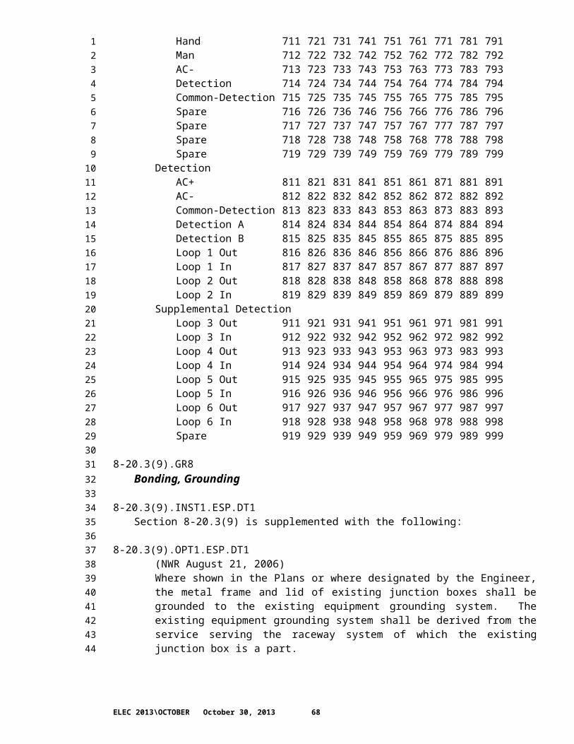
8-20.4.GR8Measurement
8-20.4.INST1.ESP.DT1The first paragraph of Section 8-20.4 is supplemented with the following:
8-20.4.OPT2.ESP.DT1(NWR August 10, 2009)Traffic Signal and Illumination System
8-20.4.OPT3.ESP.DT1(NWR August 10, 2009)Temporary Traffic Signal System
8-20.4.OPT4.ESP.DT1(NWR August 10, 2009)Temporary Illumination System
8-20.4.OPT5.ESP.DT1(NWR August 10, 2009)Temporary Traffic Signal and Illumination System
8-20.4.OPT6.ESP.DT1(NWR August 10, 2009)Temporary Video Detection System
8-20.4.OPT7.ESP.DT1(NWR August 10, 2009)Traffic Signal Interconnect System
8-20.4.OPT8.ESP.DT1(NWR August 10, 2009)Electrical System Modifications
8-20.4.INST2.ESP.DT1Section 8-20.4 is supplemented with the following:
8-20.4.OPT9.ESP.DT1(NWR August 10, 2009)Boring steel casing pipe will be measured by the linear foot for the actual length of the boring tunnel.
8-20.4.OPT10.ESP.DT1(NWR August 10, 2009)Loop replacements will be measured per each complete installation.
8-20.4.OPT11.ESP.DT1(NWR August 10, 2009)Grounding existing junction box will be measured per each junction box properly grounded.
ELEC 2013\OCTOBER October 30, 2013 68
12345678910111213141516171819202122232425262728293031323334353637383940414243444546474849505152

8-20.5.GR8Payment
8-20.5.INST1.DT1The first two paragraphs of Section 8-20.5 is supplemented with the following:
8-20.5.OPT2.ESP.DT1(NWR August 10, 2009)“Traffic Signal and Illumination System ____”, lump sum.
8-20.5.OPT3.ESP.DT1(NWR August 10, 2009)“Temporary Traffic Signal System ___”, lump sum.
8-20.5.OPT4.ESP.DT1(NWR August 10, 2009)“Temporary Illumination System ___”, lump sum.
8-20.5.OPT5.ESP.DT1(NWR August 10, 2009)“Temporary Traffic Signal and Illumination System ___”, lump sum.
8-20.5.OPT6.ESP.DT1(NWR August 10, 2009)“Temporary Video Detection System__”, lump sum.
8-20.5.OPT7.ESP.DT1(NWR August 10, 2009)“Traffic Signal Interconnect System__”, lump sum.
8-20.5.OPT8.ESP.DT1(NWR August 10, 2009)“Electrical System Modifications__”, lump sum.
8-20.5.INST1.GR8Section 8-20.5 is supplemented with the following:
8-20.5.OPT9.ESP.DT1(NWR August 10, 2009)All costs for installing conduit and junction boxes containing both signal wiring and signal interconnect shall be included in the lump sum contract prices for the associated traffic signal system bid item.
8-20.5.OPT10.ESP.DT1(NWR August 10, 2009)All costs associated with the removal of a temporary traffic signal system, temporary illumination system, temporary traffic and illumination system or a temporary video detection system shall be included in the lump sum contract price for the associated bid item.
8-20.5.OPT11.ESP.DT1(NWR October 5, 2009)
ELEC 2013\OCTOBER October 30, 2013 69
12345678910111213141516171819202122232425262728293031323334353637383940414243444546474849505152

"Loop Replacement Type ___", per eachAll costs associated with the replacement of traffic loops identified in the contract Plans as replacement loops, and the associated lead in conduit, along with the testing of the replacement loops, shall be included in the unit contract price per each for "Loop Replacement Type ___",
All pavement repair, sidewalk repair and sidewalk panel replacement costs associated with the replacement of traffic loops and conduit lead-ins shall be included in the unit contract price per each for “Loop Replacement Type__”.
When traffic loops are replaced as described under Existing Traffic Loops, all costs for replacement, along with testing of the new loops, shall be included in the unit contract price per each for "Loop Replacement Type ___".
When existing traffic loops are tested under Existing Traffic Loops, all costs for testing shall be paid in accordance with Section 1-04.4
When video detection is installed under Existing Traffic Loops, all costs associated with the video detection installation shall be paid in accordance with Section 1-04.4.
8-20.5.OPT12.ESP.DT1(NWR October 5, 2009)All costs for testing the existing detection loop, as described under Existing Loop Test, shall be included in the contract bid item associated with the detection lead-in cable installation.
All costs for replacing the existing detection loop, as described under Existing Loop Test, shall be in accordance with Section 1-04.4.
8-20.5.OPT13.ESP.DT1(NWR March 22, 2010)All costs for testing the existing detection lead-in cable, as described under Existing Lead-in Cable Test, shall be included in the contract bid item associated with the traffic loop installation.
All costs for replacing the existing detection lead-in cable, as described under Existing Lead-in Cable Test, shall be in accordance with Section 1-04.4.
8-20.5.OPT14.ESP.DT1(NWR August 10, 2009)All costs for testing preformed detector loop systems, before and after the cement concrete has been placed, shall be included in the contract bid item associated with the preformed detection loop installation.
8-20.5.OPT15.ESP.DT1(NWR August 10, 2009)“Grounding Existing Junction Box”, per eachThe unit contract price per each for “Grounding Existing Junction Box” shall be full pay for the work as specified.
8-20.5.OPT16.ESP.DT1(NWR August 10, 2009)
ELEC 2013\OCTOBER October 30, 2013 70
12345678910111213141516171819202122232425262728293031323334353637383940414243444546474849505152
All costs for adjustment of new junction boxes, both to the final grade and any grade adjustments required for the various construction stages proposed in the Contract, or for alternative stages proposed by the Contractor, shall be included in the lump sum contract price for the associated electrical system.
8-20.5.OPT17.ESP.DT1(NWR August 10, 2009)All costs for conduit, junction boxes, and associated hardware and fittings installed on or within a structural item (wall, bridge, or barrier) shall be included in the respective lump sum bid item for work on the associated electrical or conduit system.
8-20.5.OPT18.ESP.DT1(NWR March 13, 1995)The construction signs used during signal turn-on will be paid as part of "Construction Signs Class A".
8-20.5.OPT19.ESP.DT1(NWR March 22, 2010)“Adjusting Existing Junction Box”, per eachThe unit contract price per each for “Adjusting Existing Junction Box” shall be full pay for the work as specified, including but not limited to adjusting the elevation of the junction box, installation or replacement of the gravel pad and the adjustment of conduit placement within the junction box. All work shall conform to the requirements of Standard Plans J-11b, J-40.10-01 and J-40.30-00.
When the replacement or modification of electrical or communication system cables, wiring or conductors or other associated work, not identified as work in the Contract Plans, is required as a result of the adjustment of existing junction boxes, all costs associated with those modifications shall be paid in accordance with Section 1-04.4.
8-20.5.INST2.ESP.DT1The paragraph following the bid item “Conduit Pipe __In. Diam.” In Section 8-20.5 is supplemented with the following:
8-20.5.OPT20.ESP.DT1(NWR August 10, 2009)The unit contract price per linear foot for “Conduit Pipe ____ In. Diam.” shall include the backfilling of trenches and pits
8-20.5.INST3.ESP.DT1The bid item “Casing” and the reference to the bid item in the paragraph following it are revised to read:
8-20.5.OPT21.ESP.DT1(NWR August 10, 2009)"Boring Steel Casing Pipe ___ inch Diam.", per linear foot.
8-20.5.INST4.ESP.DT1The paragraph following the bid item “Directional Boring” is supplemented with the following:
8-20.5.OPT22.ESP.DT1(NWR August 10, 2009)
ELEC 2013\OCTOBER October 30, 2013 71
12345678910111213141516171819202122232425262728293031323334353637383940414243444546474849505152

The unit contract price per linear foot for "Directional Boring" shall be full pay for the directional boring regardless of the number of conduits installed in the boring tunnel.
ELEC 2013\OCTOBER October 30, 2013 72
123