Embed Size (px)
Citation preview

INDIAN INSTITUTE OF TECHNOLOGY, KHARAGPUR 721302, DECEMBER 27-29, 2002 393
Transient Analysis of Self-Excited Induction Generator with Electronic Load Controller (ELC)
for Single-Phase Loading
Bhim. Singh, S. S. Murthy and Sushma Gupta Abstract- This paper presents modeling of the electronic load controller (ELC) for three-phase Self-Excited Induction Generator (SEIG) while supplying single -phase loads. The electronic load controller regulates the terminal voltage of SEIG to constant value with variation in consumer's load. The dynamic model of the SEIG system is developed using d-q variables in stationary reference frame. For the validation of mathematical modelling, a laboratory prototype model of ELC is developed and experiments are performed on three-phase delta connected 7.5kW, 230 V, 26.2 A, 4 pole squirrel cage induction machine. Experimental results show close agreement with simulated results.
I. INTRODUCTION
In remote areas, it is difficult and costly to install grid systems, stand-alone systems are considered promising option. Moreover, such areas might have abundant natural resources like wind, waterfalls, rivers, biomass etc. Effort can be made to optimally utilize these resources to generate electrical power. Due to the schoastic nature of these resources, squirrel cage induction generator is the most suitable option to convert the mechanical energy in to electrical energy. Squirrel cage induction generator has a number of advantages like it is cheap, simpler in construction, robust, rugged, brushless rotor, absence of a separate dc source, maintenance free, self-protected against short-circuits and easily available in market [1]. However, such a generator requires external excitation, which is normally provided by a capacitor bank or by a static exciter in case of isolated system. Another major drawback of the induction generator is its inherent poor voltage regulation.
In low power range (say upto10 kW), there is considerable need of single-phase supply with appropriate generators driven by non-conventional energy sources. It has been reported that a normal single-phase induction motor could not be effectively used as SEIG, a specially designed two-winding single-phase SEIG has been proposed [2-3]. A specially designed machine requires modified manufacturing procedures and schedules, and hence expensive, the alternative of using an off the shelf three-phase induction machine as SEIG to feed single-phase load appears attractive. Bhattacharya and Woodward [4] have reported the use of three-phase SEIG feeding a single-phase load (c-2c). Shridhar et al. [5] have proposed an improved system of single-phase power generation Bhim Singh is with the Electrical Engineering Department, Indian Institute of Technology Delhi, e-mail: [email protected]. S. S. Murthy is with the Electrical Engineering Department, Indian Institute of Technology Delhi, e-mail: [email protected]. Sushma Gupta is a research scholar in Electrical Engineering Department, Indian Institute of Technology Delhi, e-mail [email protected].
using three-phase induction machine. They have used a one shunt and one series capacitor to improve the capability of the three-phase machine for single-phase loads. Shilpakar and Singh [6] have given the optimum excitation system for three-phase self-excited induction generator feeding single-phase loads to maintain the constant terminal voltage. Shilpakar and Singh [7] have given the dynamic behavior of three-phase SEIG for single-phase power generation. They have reported the initiation of self-excitation, load perturbation and short circuits behavior of the three-phase SEIG. Chan and Lai [8] have given steady state analysis of single-phase self-regulated self-excited induction generator using a three-phase machine. They have derived the performance equation using symmetrical component theory and machine parameters are determined by Hook and Jeeves method. Single-phase induction generator feeding single-phase load is rarely reported. Rahim et al. [9] have described the performance of the single-phase induction generator. Ojo [10] has given the modelling and transient performance of single-phase self-excited induction generator. He has simulated the generator self-excitation and voltage collapse phenomenon. Murthy et al. [11] have given the experimental findings on a two-winding single-phase SEIG. They have given the effect of power output, power factor, tapping in main winding and speed on the terminal voltage of SEIG. Ojo et al. [12-14] have proposed single-phase SEIG with a bi-directional single-phase PWM inverter-battery system connected to the auxiliary winding to supply the reactive power and load is connected to its main winding. In this case, battery supplies the deficit power to meet the active power demand of the load or absorbs the excess power generated by turbine. Marra and Pomilio [15] have used a PWM inverter with dc voltage to regulate the speed to keep the generated voltage constant. Many types of electronic controllers are reported in the literature [16] but dynamic behavior of three-phase SEIG with electronic load controller (ELC) is not reported while supplying single-phase loads. However, the knowledge of transient voltage, current, torque and speed are required for the proper design of ELC-SEIG system. This paper presents the dynamic modelling of ELC for a three-phase self-excited induction generator with single-phase loading. A laboratory prototype of the ELC has been designed and implemented to validate the developed dynamic model.
II. DESCRIPTION OF THE PROPOSED SYSTEM
In conventional hydro plants, a turbine governor is used to regulate the power input to the turbine because in these cases hydropower can be stored. This governor system is costly, bulky, complex in construction, requires skilled operators and frequent maintenance due to its moving

NATIONAL POWER SYSTEMS CONFERENCE, NPSC 2002 394
parts. In hilly area, population is scattered so it is better to installed small plants. Unfortunately, the cost of mechanical governing system does not reduce with small generation plants.
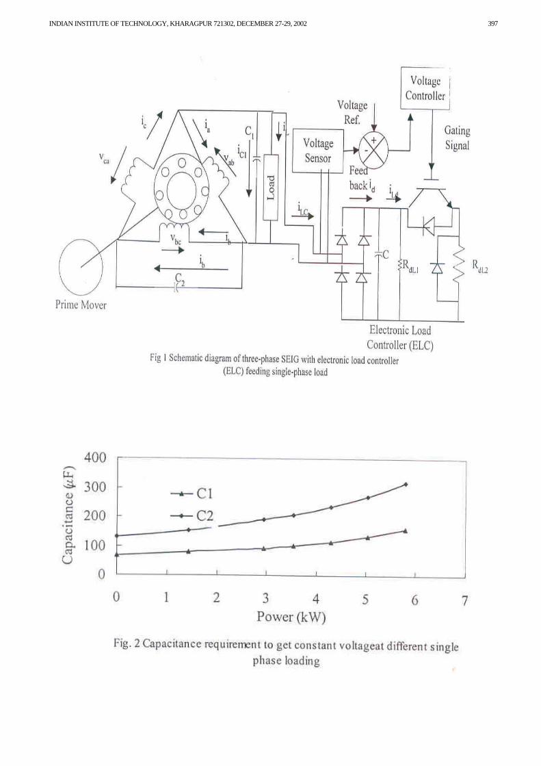
However, in stand-alone micro-hydel system, mechanical energy is obtained from running water, which is available free of cost at micro-hydel sites. Therefore, there is no restriction in using the whole available hydropower continuously. In this case, the available hydro potential is fully converted in to electrical energy thus eliminates the need of a turbine governor. As it is mentioned earlier, that induction generator does not have its own excitation so external VARs should be supplied. Capacitors are used to supplying the VARs to the SEIG system. In the proposed system connecting the sufficient capacitors across the generator according to full consumer load sets magnitude and frequency of the generated voltage. However, when the consumer load decreases the terminal voltage and frequency of the SEIG increase. It is very harmful to the health of remaining loads, which are still connected at generator terminals. So the proper voltage regulation can be achieved by keeping the effective load connected to the machine constant. This is achieved by having an electronic load controller (ELC) at the SEIG terminals. A schematic diagram of the proposed system (Self-excited induction generator, excitation system, consumer load, ELC) is shown in Fig. 1.
The principle of the load controller is that it consumes the difference between the constant output power generated by the generator and the power absorbed by the connected consumer load given as: Pout = Pd+Pc Where, Pout is generated power of the generator, which should be constant, Pc is the consumer power and Pd is the dump load power. The electronic load controller (ELC) is consisting of a single-phase uncontrolled rectifier in series with a chopper and dump load. Duty cycle of the chopper is adjusted so that the output power of the generator remains constant.
III. MODELLING OF THREE-PHASE SEIG WITH SINGLE-PHASE ELC SYSTEM
In a micro-hydel system, induction generator is the most suitable option. To make a reliable, less expensive and maintenance free generation system, mechanical governor system has to be removed which is used in conventional hydro generating systems. In self-excited induction generator, proper valued capacitors are required to generate the rated voltage at rated speed and full load. By conducting experiments capacitance value is achieved with varying loads for the design of SEIG system. Electronic load controller (ELC) with induction generator is best option for such a generation system. ELC-SEIG system operates under various transient conditions. Therefore, a dynamic model is developed of the SEIG with ELC for the transient analysis under various operating conditions such as load perturbation etc. Fig. 1 shows the schematic diagram of the proposed system. System comprises with an induction generator, capacitor bank, consumer load and ELC. A dynamic model is developed for the transient analysis of the self-excited induction generator with ELC in the following section.
1) Modelling of Self-Excited Induction Generator The dynamic model of the three-phase cage induction
generator is developed by using stationary d-q axes references frame. For the simulation purpose, voltage-ampere equations of a three-phase SEIG in d-q stationary reference frame are [17] as: [v] = [R] [i] + [L] p [i] + ωr [G] [i] (1) From eqn. [1] the current derivative of SEIG can be expressed as: p[i] = [L] –1 [v] – [R] [i] - ωr [G] [i] (2) Where [v], [i], [R], [L] and [G] are defined in Appendix I. The electromagnetic torque balance equation of SEIG is defined as: T shaft = Te + J (2/P) p ωr (3) The derivative of the rotor speed of the SEIG can be expressed from eqn. (3) as: pωr = P/(2J) (T shaft - Te) (4) Where the developed electromagnetic torque of the SEIG is expressed as [17]: Te = (3P/4) Lm (iqs idr – ids iqr) (5) The self-excited induction generator operates in the saturation region and its magenetizing characteristics is non-linear in nature. So the magnetizing current should be calculated in each and every step of integration in terms of stator and rotor currents as: im = √ (ids +idr)
2 + (iqs + iqr)2 (6)
Magnetizing inductance is calculated from the magnetizing characteristics plotted between Lm and im. Relation between Lm and im is obtianed by synchronous speed test [17] and given in Appendix II for the machine under test. Three-phase voltages and currents are obtained by converting direct and quadrature axes components into a, b and c phase voltage and current. In case of self-excited induction generator, excitation system is provided by terminal capacitors. From the Fig. 1 KCL equations of the induction generator are defined [7] as: p(vab)= (ic-ia-iL-iLC) / C1 (7a) p(vbc) = (ib-ic) / C2 (7b) For the delta connected machine, sum of the three voltages should be zero according to KVL as: vab + vbc +vca =0 (7c) Where vab, vbc and vca are the phase voltages ia, ib and ic are the phase currents iL and iLC are the consumer and ELC ac currents. 2) Modelling of Electronic Load Controller
In a micro hydel system, the self-excited induction generator generates voltage of constant magnitude and frequency. Generated voltage is kept constant in spite of variation in consumer load through ELC. ELC dumps the remaining power that is not consumed by the consumer load. Electronic load controller consists of uncontrolled rectifier bridge, control circuit and an IGBT solid-state switch. As shown in Fig 1. stator voltage is fed in to uncontrolled rectifier. As small notional value of source inductance (Lf) and resistance (Rf) is considered in the input side of the rectifier. A filtering capacitor is connected across the rectifier output to filtering out the ripples of the dc voltage. A volt-ampere relation defining the complete load controller system is as:
vmax = Rf id + Lf p(id) + vd (8)

INDIAN INSTITUTE OF TECHNOLOGY, KHARAGPUR 721302, DECEMBER 27-29, 2002 395
The current derivative of the ELC is defined as: p(id) = (vmax – vd – Rf id)/ (Lf) (9) Where vmax is the maximum value of instantaneous ac line voltages (vab and vba) depending on which diode pair is conducting. The ac load current (iLC) of ac source are achieved by using the magnitude of id and direction (sign) corresponding to conducting pairs of diodes. Charging and discharging of filtering capacitor of uncontrolled rectifier is expressed as: p(vd) = (id-iLd)/C (10) Where iLd = vd / RL1+ S vd/RL2 Where S is the switching function. When the switch is closed S = 1 and when the switch is opened S=0. The switching states of IGBT chopper (S equal to one or zero) depends on the output of voltage of PI controller, which is compared with saw tooth carrier wave resulting in PWM output of varying duty cycle.
Hence, the mathematical model of three-phase self-excited induction generator with ELC comprises nine first order non-linear differential equations ((2), (4), (7), (9) and (10)). These equations are solved using fourth order Runga Kutta method of numerical integration along with other expressions and closed loop control of ELC.
IV. IMPLEMENTATION OF PROPOSED SCHEME
In the proposed scheme, ELC consists of a single-phase uncontrolled diode rectifier and an IGBT chopper. The ac voltage is rectified by means of an uncontrolled bridge rectifier. An electrolytic capacitor is connected across the diode bridge rectifier to filtering out the ripples. The dump load in series with the chopper switch is connected across the dc link. The dump load is designed such that, when the duty cycle of the chopper is unity it should consume the rated output power of the generator. A free wheeling diode is connected across the dump load for circulation of the stored energy in the dump load when the chopper switch is OFF.
The output power of the SEIG is kept constant by control circuit. The terminal voltage is stepped down by a step down transformer and then rectified and filtered by a small capacitor to get a dc value proportional to the SEIG output voltage (feedback signal). This is compared with a reference voltage signal, which is taken proportional to the rated terminal voltage of the generator. A proportional integral (PI) voltage controller is used for the comparison of feedback signal and reference signal. A PWM signal is generated by the comparison of output of PI controller and saw tooth carrier waveform. All these functions- PI controller and PWM controller are realized by a PWM controller IC 3525. The IC 3525 has an internal saw tooth generator the frequency of which can be designed externally by having a resistor and capacitor. The gains of the PI controller can be varied externally by means of having potentiometers.
The PWM signal is fed to an opto-isolator, which gives isolation between the power circuit and the control circuit. The opto-isolator inverts the signal at its output and hence a single stage transistor amplifier is used at its output, which again inverts the signal to regain the original signal. This signal is then fed to a push pull amplifier, which drives IGBT chopper with appropriate duty cycle.
V. RESULTS AND DISCUSSION
In the laboratory test rig, a three-phase, 240 V, 26.2 A, 7.5 kW, 4 pole, ∆ connected squirrel cage induction machine is coupled to a closed loop speed controlled converter-fed dc motor. It operates as a constant speed prime mover for the different loads. The machine parameters and magnetizing characteristic of the induction generator is given in Appendix II. Experiments are carried out on developed prototype of the ELC to verify the validity of the derived mathematical models.
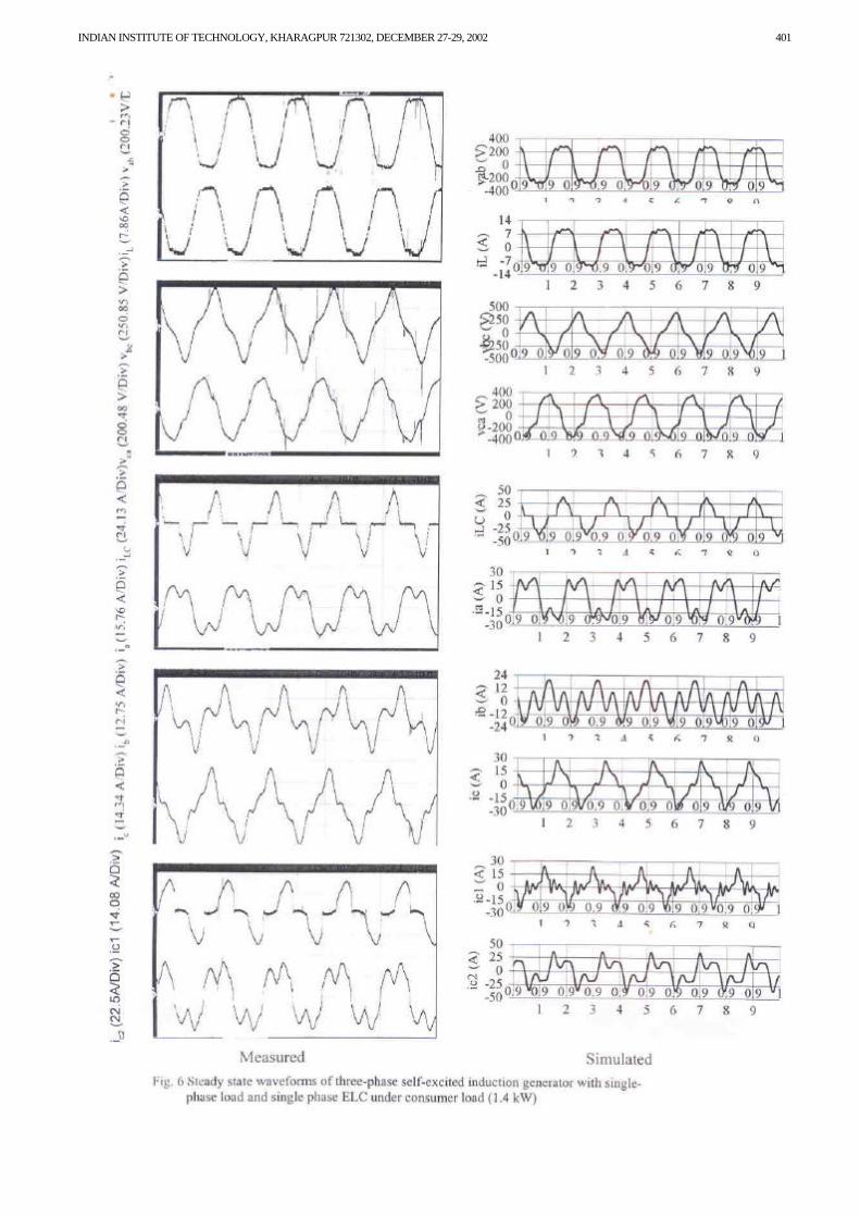
For the single point operation of the self-excited induction generator, at the constant speed of prime mover the capacitance corresponding to rated voltage at rated power is required to design ELC. Fig. 2 shows the variation of capacitance with power output of the SEIG at constant terminal voltage. It is observed that required capacitances are 65.67 µF and 130.31 µF at no load and 158.03 µF and 318.96 µF for 5.8 kW load. It is also observed that approximately double capacitance is required in the leading phase as compared to the phase, which is having load and capacitance. Fig. 3 shows transient waveforms of the three-phase SEIG with single-phase ELC at sudden application of single-phase consumer load (1.4kW). It is observed that due to single-phase load and single-phase, ELC generator voltages and currents are unbalanced in three phases. It is observed that terminal voltage remains constant at the application of consumer load. It can be seen from this figure that as consumer load (iL) increases dump load current (iLC) decreases to keep the constant voltage of the three-phase SEIG. However, small dip in generator current and capacitor current is also observed but stabilized within few cycles. Fig. 4 shows transient waveforms of the three-phase SEIG with single-phase ELC at the removal of the consumer load. It is observed that when the consumer load (1.4 kW) is removed from three-phase SEIG, terminal voltage remains constant. It is observed that as consumer load current (iL) decreases, ELC dumpes extra power in dump load to keep the constant voltage at the three-phase SEIG resulting in increased value of ELC current (iLC).
Fig. 5 shows the steady-state waveforms of three-phase SEIG with ELC under zero consumer load condition. At zero consumer loads, ELC is more effective. Fig. 6 shows the steady-state waveforms of the three-phase SEIG with ELC at consumer load. At consumer load, ELC current (iLC) decreases to maintain constant power output of SEIG. It is observed that the ELC introduces harmonics in the generator terminal voltage. Fig. 7 shows the harmonic spectrum and THD under both above conditions. Under zero consumer loads, ELC draws higher value of ac current, which is nonsinusoidal in nature resulting in higher THD in generator voltage.
VI. CONCLUSIONS
A mathematical model of three-phase SEIG supplying single-phase consumer load with ELC has been developed and verified with experimental results. Based on a close agreement between the simulated and experimental results, it can be concluded that the approach made in the development of dynamic model is elegant. The dynamic behavior of the three-phase SEIG with load controller has revealed that this system can be used satisfactorily in micro-hydel application. With the help of load controller, a

NATIONAL POWER SYSTEMS CONFERENCE, NPSC 2002 396
micro-hydel system may be installed easily and economically in remote locations.
VII. Appendix I
Matrices of eqn (1) is defined as:
[v] = [vds vqs vdr vqr] T [i] = [ids iqs idr iqr]
T [R] = diag [ Rs Rs Rr Rr] [L] = Ls+Lm 0 Lm 0 0 Ls+Lm 0 Lm Lm 0 Lr+Lm 0 0 Lm 0 Lr+Lm [G] = 0 0 0 0
0 0 0 0 0 -Lm 0 Lr+Lm Lm 0 Lr+Lm 0
APPENDIX II
The equivalent parameters of the induction machine are obtained by the dc resistance test and block rotor test. The measured equivalent circuit parameters are as:
Rs = 1Ω, Rr = 0.77Ω and Xls = Xlr = 1 Ω. Magnetising characteristics of the induction machine is achieved using synchronous speed test in form of Lm vs im curve.
VIII. ACKNOWLEDGEMENT
The authors would like to sincere thank to the Department of Science & Technology (DST), Govt. of India for sponsoring and funding.
IX. REFERENCES [1] S. S. Murthy, O. P. Malik, A. K. Tondon, “Analysis of self excited induction generators," IEE Proc., Vol.129, Pt.C, No. 6, pp. 260-265, November 1982. [2] S. S. Murthy, “A novel self-excited self regulated single-phase induction generator part1-basic system and theory," IEEE Trans. on Energy Conversion, vol. 8, No. 3, pp. 377-382, September 1993. [3] S. S. Murthy, H. C. Rai and A. K. Tandon, “A novel self-excited self regulated single-phase induction generator part II-Experimental verification," IEEE Trans. on Energy Conversion, vol.8, No. 3, pp. 383-388, September 1993. [4] J. L. Bhattacharya and J. L. Woodward, “Excitation balancing of a self-excited induction generator for maximum power output,” IEE Proc., Vol. 135, Pt. C, No. 2, pp. 88-97, March 1988. [5] L. Shridhar, B. Sinsh and C. S. Jha, “Options for single-phase power generation in isolated application using cage generators,” Journal of institution of Engineers (India) Pt. EL, Vol. 76, pp.222-227, February 1996. [6] L. B. Shilpakar and Bhim Singh, “Optimum excitation for three-phase self-excited induction generator feeding single-phase loads,” IEEMA Journal, Vol. XVI, pp. 7-15, July 1996. [7] L. B. Shilpakar and Bhim Singh, “Dynamic behaviour of a three-phase self-excited induction generator for single-phase power generation,” Electric Power System Research, Vol. 48, pp. 37-44, 1998. [8] T. F. Chan and L. L. Lai, “A novel single-phase self-regulating self-excited induction generator using a three-phase machine,” IEEE Trans. on Energy Conversion, Vol. 16, No. 2, pp. 204-208, June 2001. [9] Y. H. A. Rahim, A. I. Alolah and R. I. Al-Mudalheem, “Performance of single-phase induction generators,” IEEE Trans. on Energy Conversion, Vol. 8, No. 3, pp. 389-395, September 1993. [10] O. Ojo, “The transient and qualitative performance of a self-excited single-phase induction generator,” IEEE Trans. on Energy Conversion, Vol. 10, No. 3, pp. 493-501, September 1995. [11] S. S. Murthy, H. C. Rai, Bhim Singh, B. P. Singh, N. K. Goyal and M. O. Vaishya, “New experimental findings on a novel two-winding single-phase self-excited induction generator for standby power generation,” Proc. of International Conference on Power Electronics, Drives and Energy Systems for Industrial Growth, Vol. 2, January 1996, pp. 674-678. [12] O. Ojo and B. Gonoh, “A controlled stand-alone single-phase induction generator,” IEEE International Conf. On Power Electronics Drives and Energy Systems, New Delhi, January 1996, pp. 694-699. [13] O. Ojo, O. Omozusi and A. A. Jimoh, “Expanding the operating range of a single-phase induction generator with a PWM inverer,” IEEE Conf. On Industry Applications, Twenty-Third IAS Annual Meeting, Vol. 1, 1998, pp. 205-212. [14] O. Ojo, O. Omozusi and A. A. Jimoh, “Performance of an autonomous single-phase induction generator with a bidirectional PWM inverter-battery system in the auxiliary winding,” IEEE International Symposium on Industrial Electronics, ISIE’98, Vol. 1, 1998, pp. 306-311. [15] E. G. Marra and J. A. Pomilio, “Induction generator based system providing regulated voltage with constant frequency,” IEEE Applied Power Electronics Conf. and Exposition, APEC’99, Fourteenth Annual Meeting, Vol. 1, 1999, pp. 410-415. [16] R. Bonert and G. Hoops, “Stand alone induction generator with terminal impedance controller and no turbine controls,” IEEE Tran. on Energy Conversion, Vol. EC-5, No. 2, pp. 28-31, March 1990. [17] L. B. Shilpkar, “Analysis of self-excited induction generators supplying single-phase and three-phase loads,” Ph. D. Thesis, Electrical Engineering Department, IIT, Delhi, India, July 1997.
Fig. A1 Variation of magnetising inductance with magnetising current
Lm = 5E-05Im3 - 0.0012Im
2 + 0.0014Im + 0.1407
0
0.02
0.04
0.06
0.08
0.1
0.12
0.14
0.16
0 5 10 15 20Im (A)
Lm (H
)
INDIAN INSTITUTE OF TECHNOLOGY, KHARAGPUR 721302, DECEMBER 27-29, 2002 397

NATIONAL POWER SYSTEMS CONFERENCE, NPSC 2002 398

INDIAN INSTITUTE OF TECHNOLOGY, KHARAGPUR 721302, DECEMBER 27-29, 2002 399

NATIONAL POWER SYSTEMS CONFERENCE, NPSC 2002 400
INDIAN INSTITUTE OF TECHNOLOGY, KHARAGPUR 721302, DECEMBER 27-29, 2002 401

NATIONAL POWER SYSTEMS CONFERENCE, NPSC 2002 402