Embed Size (px)
Citation preview
Indian Journal of Data Communication and Networking (IJDCN)
ISSN: 2582-760X (Online), Volume-1 Issue-1, December 2020
1
Published By:
Lattice Science Publication Retrieval Number: 100.1/ijdcn.A1001121120
Journal Website: www.ijdcn.latticescipub.com
Various Techniques for Wireless Power Transfer
Parul Arora
Abstract:Electric &magnetic fields (EMF) are made by
empowerd elements in issue, for example, electrons. A fixed
empower makes an electrostatic-field in the area around it. A
consistent current of empowers (direct current, DC) makes a
static engaging field in the area around it. The above mentioned
fields contain energy, at any rate can't pass on power since they
are set static. Anyway time-moving fields can pass on power.
Enlivening electric-empowers, for example, are found in an
alternating current (AC) in a wire of electrons; make time-
differentiating EMF in the areanearby them. This fields may
apply impacting powers on the moving electrons in an enduring
"radio wire", making them push ahead and in reverse. These
speak to AC can be utilized to empower a heap. The affecting
EMF remembering moving electric-empowers for a radio wire
gadget can be disengaged into two regions, subordinate upon
segment stretch out from the accepting wire. The limit between
the areas is to some degree tragically portrayed. The fields having
diverse features in these areas, and various technologies are
designed for transferring power.
I. INTRODUCTION
WPT is the transmission of the electrical-energy deprived of
wires as a physical association. In a WPT structure, a
transmitter contraption is driven by electric power. Power is
used from a power source connected to direct supply. It
creates a time-dependent electro-magnetic field. This field
sends power through space to a recipient device.The
recipient devices collect power from the generated field and
provide it to electrical devices. The advancement of WPT
can discard the usage of the power supplying wires and the
power storing batteries, along these lines growing the
transportability, security, and prosperity of electronic
contraption for all the users.[1] WPT is significant to power
electrical devicesasconnecting wires is off-kilter, dangerous,
or are unreasonable. WPT procedures for the most part fall
into two classes, near/close field and far/long-field.
Near/close field is also called as non-radioactive systems. In
this field power is moved over short partitions by MF using
inductive-coupling between twists in wire, or power is
moved by EFs (EF) using capacitive-coupling among metal
electrodes.[2] In near /close field the inductive-coupling is
the most comprehensively used as a wireless advancement.It
is used to join charging the different portable devices like
tooth-brushes, phones, RFID marks and wirelessly
empowerd WPT in implantable clinical devices like phony
cardiovascular pace-makers, or EV.[3] In far/long-field or
radioactive techniques power is moved by light discharging
radiation, like laser light transmission or microwaves
transmission [4]. These strategies can move power longer
partitions anyway ought to be centered on the authority.
Projected applications for this category are solar (sun)
powered energy satellites, and WPT based robot airplane.
[5] A huge issue related with entirely WPT systems may be
harmful EMFto people and other living creature. [6] Revised Manuscript Received on November 05, 2020.
ParulArora, JagdishprasadJhabarmalTibrewala University Churu Rd, Vidyanagari, Churela, Rajasthan
© The Authors. Published by Lattice Science Publication (LSP). This is an open access article under the CC BY-NC-ND license
(http://creativecommons.org/licenses/by-nc-nd/4.0/)
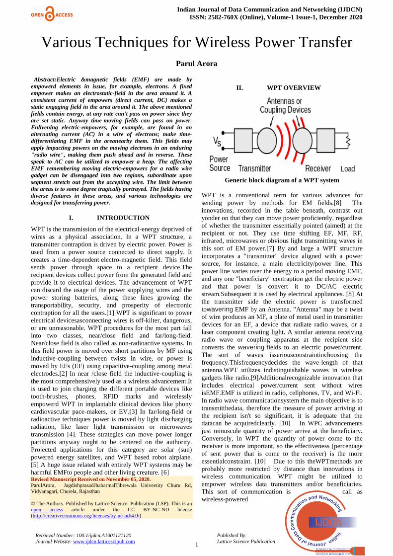
II. WPT OVERVIEW
Generic block diagram of a WPT system
WPT is a conventional term for various advances for
sending power by methods for EM fields.[8] The
innovations, recorded in the table beneath, contrast out
yonder on that they can move power proficiently, regardless
of whether the transmitter essentially pointed (aimed) at the
recipient or not. They use time shifting EF, MF, RF,
infrared, microwaves or obvious light transmitting waves in
this sort of EM power.[7] By and large a WPT structure
incorporates a "transmitter" device aligned with a power
source, for instance, a main electricity/power line. This
power line varies over the energy to a period moving EMF,
and any one "beneficiary" contraption get the electric power
and that power is convert it to DC/AC electric
stream.Subsequent it is used by electrical appliances. [8] At
the transmitter side the electric power is transformed
towavering EMF by an Antenna. "Antenna" may be a twist
of wire produces an MF, a plate of metal used in transmitter
devices for an EF, a device that radiate radio waves, or a
laser component creating light. A similar antenna receiving
radio wave or coupling apparatus at the recipient side
converts the wavering fields to an electric power/current.
The sort of waves isseriousconstraintinchoosing the
frequency.Thisfrequencydecides the wave-length of that
antenna.WPT utilizes indistinguishable waves in wireless
gadgets like radio.[9]Additionalrecognizable innovation that
includes electrical power/current sent without wires
isEMF.EMF is utilized in radio, cellphones, TV, and Wi-Fi.
In radio wave communicationsystem the main objective is to
transmitthedata, therefore the measure of power arriving at
the recipient isn't so significant, it is adequate that the
datacan be acquiredclearly. [10] In WPC advancements
just minuscule quantity of power arrive at the beneficiary.
Conversely, in WPT the quantity of power come to the
receiver is more important, so the effectiveness (percentage
of sent power that is come to the receiver) is the more
essentialconstraint. [10] Due to this theWPTmethods are
probably more restricted by distance than innovations in
wireless communication. WPT might be utilized to
empower wireless data transmitters and/or beneficiaries.
This sort of communication is call as
wireless-powered

Various Techniques for Wireless Power Transfer
2
Published By:
Lattice Science Publication Retrieval Number: 100.1/ijdcn.A1001121120
Journal Website: www.ijdcn.latticescipub.com
communication (WPC). At the point when the gathered
power is utilized gracefully to empower the wireless data
transmitters, the system is known as Simultaneous-Wireless
Information and Power-Transfer (SWIPT); though when it is
utilized to flexibly the power of wireless data beneficiaries,
it is called as a Wireless-powered Communication-Network
(WPCN).[21]
Table 1 Comparison between different WPT
III. HISTORY
The nineteenth century saw numerous advancements of
counter-hypotheses, and speculations on how power of
electricity may be sent. André-Marie Ampère in 1826
discovered Ampère's law indicates electric current creates an
MF.[11] In 1831 Michael Faraday portrayed law of
enlistment,in which he explained the electro-motive power
controlling flow of a current in a conveyor circle by a period
changing magnetic transition. Conduction of electrical
power deprived of wires were seen by numerous
experimenters and designers,[12] however absence of a
lucid hypothesis ascribed these wonders dubiously to
induction in EMF.[13] James C. Maxwell in 1860s give
brief clarification of these marvels that would originate from
the his different equations. [14] He building up a
hypothesis which brought together magnetic
andelectricpowertoformEM (EM), foreseeing the presence
of EM waves by means of the "wireless" transporter of EM
power. John H. Poynting around 1884 gave Poynting's
hypothesis and characterized Poynting vector that portray
the progression of electric energy over a zone inside EM
radiation and take into account a right investigation of WPT
systems. [14] In 1888 Heinrich R. Hertz' proposed approval
of the hypothesis, that introducedthe proof for different
radio waves.William Henry Ward (1871) and Mahlon
Loomis (1872) were placed two plans of signaling in
wireless environment that depended on the incorrect faith
that an electric environmental layer available at low altitude.
Both innovators' licenses noticed this layer associated with
an arrival way utilizing "Earth currents"' would take into
consideration wireless telecommunication just as flexibly
power for the message, getting rid of counterfeit batteries,
and that could likewise be utilized for warmth,lightingand
thought process power.Furtheruseful exhibition of WPT by
means of transmission came in 1879 by Amos Dolbear's,EM
phone that havingpowdered conduction to communicate
about a separation of few miles.
IV. TESLA
WPT is explained by Tesla for the duration of 1891 through
"electro-static induction" in talk at Columbia College. Tesla
coil oscillator consists of two metal sheets, which applies
alternating current with high-voltage radio frequency . A
smart EF between the sheets ionizes the gas having low-
pressure in the two lengthy Geissler tubes, making them
glow like neon tubes.Nikola Tesla, after 1890 explored
different avenues regarding communicating power by
capacitive and inductive coupling utilizing sparkle
energized RF resounding transformers, presently known as
Tesla_coil, which created AC voltages highly.[15] When he
attempted to build up a wireless transfer light
frameworkdependent on close field inductive coupling and
capacitive coupling[16] and directed a progression of open
shows where he set alight Geissler tubes and
alsoluminescent blubs lights above a phase.[16] He
discovered that he could illuminate the bulb using an
accepted LC circuit to reconstitute through the LC circuit of
transmitter.[15] utilizing full inductive power coupling.[16]
The Tesla was unsuccessful to brand a business item out of
its invention but its inductive power coupling connectivity
strategy is now commonly used in hardware and is presently
being practical to short distance WPT
systems.[16]Experimentation in resounding inductive power
transfer at Colorado Springs in 1899 by Tesla.
Fig.1 Tesla's power-station at Wardenclyffe.
He proceeded to build up a WPT circulation framework,
which he trusted might be equipped for communicating
power. The power is communicated over significant
distance and utilized openly into households and processing
plants. At an opportune time he appeared to acquire from
thoughts of scientist Mahlon Loomis,who suggesting a
framework made out of inflatables balloons to
appendtransferringand accepting conductors noticeable all
around in the air over 9,100 m (30,000 feet) in elevation,
where he

Indian Journal of Data Communication and Networking (IJDCN)
ISSN: 2582-760X (Online), Volume-1 Issue-1, December 2020
3
Published By:
Lattice Science Publication Retrieval Number: 100.1/ijdcn.A1001121120
Journal Website: www.ijdcn.latticescipub.com
figured the weight would permit him to transferhigh power
voltages (volts in a large number) at significant distances.
Additionally consider the idea of low weight air flow he
formed a test office in Colorado Springsat huge height
during 1899.[13] Research he led in that office with an
enormous coil with working in the megavolts extend, just as
perceptions he completed of electronic smash of lightning
airstrikes, but he determined theresultimproperly[17] which
he might be utilize in the entireearth to direct electrical
power. Hypothesis involvedpowerfulACpulses into Earth on
its thunderous frequency from a stranded Tesla loop
neutralizing a raised capacitance to cause the capability of
Earth to waver. Tesla figured this would permit AC to be
gotten alongwith a comparative capacitive power antenna
adjusted to reverberation with that anytime on Earth with
almost no loss of power. His perceptions likewise persuaded
aextraordinary voltage utilized by a loop on a rise of a
littlehundreds of feet would "collapse the air band",
disposing of the requirement for a significant distance of
link holding tight inflatables to make his climatic return
circuit.Tesla will next year propose a "world WPT system"
that will transmit both information(or data) and power
around the world.[17] In New York at Shoreham(1901) he
endeavored to build a huge WPT station, presently known
asWardenclyffePowerTower, yet in 1904 venture
evaporated and that office was rarely finished.
Fig. 2WPT Technologies
V. WPT TECHNOLOGIES
• Close-field or nonradioactiverange – This implies the
zone inside around 1 frequency (λ) of the antenna.[8] In
this area the smartEMFare separate[9] and power could
be transferred through EFs by capacitive power coupling
amongmetallic electrode,[3] or by means of MFs by
inductive power coupling among loops of wires.[10]
These arenasaren‟tradioactive,[18] implicationthatthe
power remains inside a short separation of the
transmission.[19] If there is no collecting gadget or
retaining material inside their restricted series to
"couple" to transmitter, then no power is released by the
transmitting device.[19] The range of these fields is
small and usually depends on the size and position of the
"antennas" with wire coils.Inthis manner the power
interconnected in this fields decline exponentially with
distance,[20] therefore if the separation among the two
"antenna" is a lot bigger than the breadth of the " antenna
" exact slight power would be acknowledged (received).
In this way, these methods can't be utilized for long
distance power communication. Resonance inductive
power coupling can build the coupling among the
antennas enormously, permitting proficient transmission
at to some degree more noteworthy distances,[8] in spite
of the fact that the fields despite everything decline
exponentially. In this manner the scope of close field
gadgets is customarily separated into two classifications:
o Short range – capable of around one
antennabreadth:Drange ≤ Dant[8] in this range a normal
non-resonant inductive power coupling or capacitive
power coupling can transmissionrealistic measures of
power.
o Mid-range –capable of multiple times (10 times) the
reception apparatus distance across: Drange ≤ 10 Dant.
[21] In this range a normal resonant inductive power
coupling or capacitive power coupling can transmission
realistic measures of power.
• Far-field or radioactiveregion – Away
frommore than 1 frequency (λ) of the antenna, the EMF are
opposite (perpendicular) to one another and proliferate as an
EM wave; models are microwaves, radio waves, or light
waves.[8] This piece of the power is radioactive,[18]
meaning it give out the reception apparatus whether there is
a recipient to retain it or not. The part of power which
doesn't reach to the accepting antenna is scattered and lost to
the framework. The measure of power disempowerd as EM
waves by a reception apparatus relies upon the proportion of
the radio size of antenna Danttothe frequency of the
influencesof waves λ,[18] which is controlled by the: λ = c/f.
By the side of low frequencies f in which the antenna is a lot
littler than scope of waves, Dant<< λ, next to no energy is
emanated. Consequently close field gadgets use lower
frequencies; emanate practically none of their power as EM
radiation. A similar size Antennas as the frequency Dant≈ λ,
emanate power proficiently in dipole or monopole reception
apparatuses.TheEM waves are transmitted in all ways
(Omni-directionally), therefore if the getting antennasareat
long distance, just a modest quantity of radiation will
success to reachantenna.[18]Hence, it can be utilized for
small range power transmission and not for long distance
powertransmission.Be that as it may, in contrast to fields,
EM radiation can be engaged by refraction or reflection into
shafts. Through utilizing a high-gain reception apparatus or
ophthalmic framework that gathers the power emission into
a thin pillar focused on the collector, it very well may be
utilized for long distance power/energy transmission. [21]
Rayleigh model states that, to deliver the limited bars
important to center a lot of the power on a far off
beneficiary.Aantenna must be a lot bigger than the
frequency of the utilized waves: Dant>> λ = c/f. Hands-on
shaft power gadgets need frequencies in the centimeter
locale or beneath, relating it over 1 GHz, in the MV
frequencies extend or overhead.[14]
VI. CLOSE FIELD (NONRADIOACTIVE)
METHODS
Everywhere relative separation, the close field parts of EMF
are roughly semi-static wavering dipolar fields.
The dipolar fields decline along with cubic distance of
shape: (Drange/Dant)-3
[18]Subsequently power is relative to
the rectangle of field quality, the power/energy transferred
diminishes as (Drange/Dant)−6
or around 60dB for each years.
At the end of the day,
Various Techniques for Wireless Power Transfer
4
Published By:
Lattice Science Publication Retrieval Number: 100.1/ijdcn.A1001121120
Journal Website: www.ijdcn.latticescipub.com
if far separated, multiplying the separation among the two
reception apparatuses effect the power/energy got to
diminish by aaspect of 26 = 64. Subsequently, inductive
power coupling and capacitive power coupling must be
utilized for small distanceenergy transfer, inside a couple of
time the distance across the reception apparatus (antenna)
gadget Dant. Not at all like in a radioactive framework where
the most extreme radiation happens after the dipolar antenna
arranged cross over to the route of broadcast, by dipole
handle the greatest coupling happens after the dipole is
situated longitudes direction.
VII. INDUCTIVE COUPLING
Inductive power coupling is the ancient and utmost
generally utilized WPT innovation. For all intents and
purposes it is utilized in business items. It is utilized in
inductive power charging of different devices stands for
wireless apparatuses utilized in wet conditions to lessen the
danger of electric shockwave, for example, shavers and
electric toothbrushes. Additional application zone is
"Transparent" energizing of bio-medical gadgets embedded
in individual‟s body to escape from consuming wires going
inside the skin, for example, insulin siphons and
cardiovascular pacemakers. It is likewise utilized to
empower EV, for example, bus and to either empower or
charge travel vehicles like transports and trains. Anyway the
quickest developing utilize is cordless empowering pads to
revive portable and regular hand held cordless gadgets, for
example, tablet and PCs, smartphones, computer game
controller and computerized television player. [14] The
first confirmation to a WPT charging framework in Dec.
2017 given by United States. [15]
In the inductive power coupling (electro-magnetic induction
or inductive transfer of power IPT), power is
transportedamong loops of wire by an MF.[9] The sender
and collector curls collectively structure a transformer[9].
An AC from side to the spreader loop (L1) makes a
smartMF (B). The MFpassesover the reception loop (L2),
wherever it initiates an irregularelectro-magnetic field
(voltage), that makes an AC in the reception end.[10] It
incited AC may either run the electric devices
conventionally, or staymodified to DC through a rectifiers
available in the recipient, thatruns the devices. A couple of
frameworks, for example, rotary brush and charging stands,
operates at 50 Hz or 60 Hz so current from AC is utilized
directly to the sender loop, yet now many frameworks of the
electronic vacillator creates aadvancedfrequencyalternate
current thatruns the curl, since communication effectiveness
expandsthrough frequency of receiver.
Fig. 3 The block illustration of an inductive WPT system
The power/energytransported increments
byfrequencyrate[22] and the common inductance among the
loops,[10]thatrely upon system‟s geometric position and the
separation among them. A broadly utilized figure of
legitimacy is the coefficient of coupling.Thiselement
boundary is equivalent to the part of MF through the
sendercoilswhich goes through the beneficiary loop while
L2 is unclosed circuit. On the off chance that the both loops
are on a same pivot and adjacentcomposed so all the MF
transition drivesover it and the connection
throughputimpacts 100%. The more prominent the division
between the loops, the a greater amount of the MFthrough
the principal curl omissionsto second coil and the
connection productivity are the lower, moving toward zero
next to great distance.The connection proficiency and power
transferred is generally corresponding to.In request to
attaingreatusefulness, the curls necessity be exceptionally
near each other, a small amount of the curl distance
acrosstypically inside centimeters,[21] adjusted with the
loops' axis. The loop shapes levels are normallyutilizedto
increment coupling.Ferrite "transition imprisonment" hubs
can limit the MFs, lessening obstruction and improving
coupling to electronic devices. [22] These devices are
heavyweight and huge so tinycordless gadgets frequently
use aircenter curls. Standard inductive power coupling may
possibly accomplish great effectiveness while the loops are
extremely near one another, typically contiguous. In most
current inductive frameworks thunderous inductive power
coupling is utilized, in that the effectiveness is expanded
through utilizing resounding circuit.[18] This mayleads to
high productivities at more prominent separations as
compared tonon-resonates inductive power coupling.
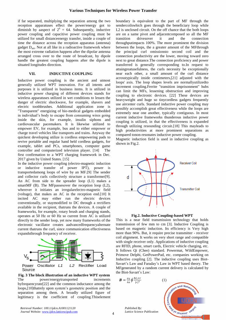
Magnetic induction field is used in inductive coupling as
shown in Fig.2.
Fig.2. Inductive Coupling-based WPT
This is a near field transmission technology that holds
transmission of few mm to cm [3]. Inductive Coupling is
based on magnetic induction. Its efficiency is Very high
more than 90%. But, it require precise transmitter - receiver
coil alignment. It works on very short range and compatible
with single receiver only. Applications of inductive coupling
are RFID, phone, smart cards, Electric vehicle charging, etc.
It follows Qi (Chee) standard. Powermat, WildEmpower,
Primove Delphi, GetPowerPad, etc. companies working on
Inductive coupling [2]. The inductive coupling uses Biot-
Savart‟s Law and Faraday‟s Law in WPT based theory. The
MFgenerated by a random current delivery is calculated by
the Biot-Savart‟s Law:
𝑩 =𝜇0
4𝜋
𝑰𝑑𝐼×𝑟
|𝑟|3 (1)

Indian Journal of Data Communication and Networking (IJDCN)
ISSN: 2582-760X (Online), Volume-1 Issue-1, December 2020
5
Published By:
Lattice Science Publication Retrieval Number: 100.1/ijdcn.A1001121120
Journal Website: www.ijdcn.latticescipub.com
Where I is current, μ0 is magnetic constant, dI vector r is
full displacement vector.
The induced voltage over the receiver coil VInd is
calculated by Faraday‟s Law using rate of MFisB alteration
through an operative surface region S by:
𝑉𝐼𝑛𝑑 = −𝜕
𝜕𝑡 𝐵.𝑑𝑠 (2)
The drawback of the WPT based on inductive coupling is its
short distance transmission.
VIII. CAPACITIVE WPT FRAMEWORKS
Capacitive power coupling likewise alluded to as electrical
power coupling. It utilizes EFs for the transfer of power
among two terminals cathode and an anode. That terminal
forms a capacitance for the transmission of
power/energy.[23] In capacitive power coupling
electrostatic induction is created.This inductive power
coupling is connected to communicate power by EFs among
electrode sheets[5], for example, metal sheets. The
transmitter electrode and beneficiary electrode structure a
capacitor. The capacitor ishaving the mediating space as the
dielectric.[5] A changing voltage created by the sender is
used to the communicating plate, and the smartEF instigates
achangingpotential on the collector plate by electrostatic
power induction.[10] This induction makes an AC stream in
the heap circuit. The measure of power transported
increments with the square frequency of the voltage, and the
capacitance among the metal sheets.This is corresponding to
the region of the littler plate (for small separations) and
conversely relative to the distance.[10]
Mono polar charging
coupling
Bipolar charging
coupling
Capacitive power coupling has just been utilized for all
intents and purposes in a couple of low
powertransmissionapplications.In light of the fact that the
high voltages on the terminals required to communicate
small power may be risky.[9]It may cause undesirable
symptoms, for example, toxic ozone creation. Likewise,
rather than MFs, [21] EFs interface unequivocally with
maximum materials because of dielectrically polarized
including human body. [23]Overriding materials
amongelectrodesor close to the cathodes can ingest the
power, on account of people conceivably causing
unreasonable EMFdisclosure.[9] On the other hand
capacitive power coupling has a couple of preferences over
inductive power coupling. The MF is to a great extent
restricted between the sheets of capacitor, lessening
obstruction, that in inductive power coupling needs
substantial ferrite "motion(flux)containment" centers.[10]
Similarly, arrangement necessities among the sender and
recipient are fewerdangerous.[10] Capacitive power
coupling has freshly applied to empoweringmobile devices,
which are battery powered [3] alsoempoweringor nonstop
WPT in biomedical devices.[4] It is deliberated as a
methods for transporting power/energyamongisolatedsheets
in coordinated circuits of the system.[24]
Capacitive coupling is Near-field (NCC) transmission based
WPT scheme proposed by Rangarajan Jegadeesanand el. at
in [4]. They identified that NCC can work in sub GHz
frequency range. This is the capacitive scheme basically
designed for improvement of efficiency and flexibility of
implants. NCC work on principle of movement currents.
Itconsists of 2 conductorsTX–RX couples at distance D,
effective area A, when time-varying voltage, V(t) applied
current passes through source.Magnitude of conduction in
addition tomovement current given below in [4] as follows,
𝐼𝑑𝑖𝑠𝑝 = Ԑ0Ԑ𝑟 𝜔 𝐴𝜕Ẽ
𝜕𝑡 (3)
Idisp is representing the current movement of sheets.
Ԑ0 -- free space permittivityamong the two sheets
Ԑr(ω) – represent the relative permittivity based on
frequency.
𝐼𝑐𝑜𝑛𝑑 =𝑉(𝑡)𝜎(𝜔)𝐴
𝐷 (4)
Icond is representing the current conduction of sheets.
σ (ω) represents conductivity of the material for couple of
conductor sheets.
User can increase efficiency of WPT by increasing electrical
field rate and area between the conductors eq. (3). However,
eq. (4) shows that reducing the transmission current
needsdropping the actual conductor range and the voltage
[4].
Two kinds of circuit have been utilized:
Transverse design:
It contains 2sendersheets and 2 recipient sheets in this kind
of circuit. Eachsenderplate is united to a recipient plate. [4]
The sender oscillator runs the sender sheets in reversephase
(i.e. 180°ofstagetransformation) in a greatshifting voltage,
and the heap is associated among the two recipient sheets.
The shifting EFs initiate inverse stage shifting possibilities
in the collector sheets, and this "pushandpull" activity makes
current stream to and fro between the sheets through the
heap. A drawback of this setup for cordless empowering is
that the two sheets in the accepting gadget must be adjusted
up close and personal to the empowersheets for the gadget
to charge properly.[16]
Longitudinal design:
It consists of the sender and collector with just a single
dynamic cathode, and either the ground or a huge aloof
anode fills in as the arrival method for current in that
sheets/plates. The sender waver is associated among a
functioning and a uninvolved anode. The heap is likewise
associated among a functioning and a detached anode. The
EF created by the sender incites interchangingvoltage
(charge) uprooting in the heap dipole via electrostatic power
induction. [10]
IX. MAGNETIC COUPLING
This type of technique is having a power/energythat
communicated among two turningstructures, first in sender
and second in collector.This structure pivot simultaneously.
They areattached together through a MF created via
perpetual

Various Techniques for Wireless Power Transfer
6
Published By:
Lattice Science Publication Retrieval Number: 100.1/ijdcn.A1001121120
Journal Website: www.ijdcn.latticescipub.com
magnets arrangedonthatstructure.[25] The senderstructureis
turned by rotating coil of an electric engine.ItsMFputforce
on the beneficiary structure, revolving it in the structure.
The MFworks like a machine-driven coupling among the
structures.[25] The beneficiary structuregenerates
power/energy to run the heap, moreover by rotating a
different electricalproducer or by utilizing the collector
structurethemself as the propeller in thatproducer.
The gadget had projected as an alternative to dynamic power
transmission for non-contact empowering of electrical
transportation vehicles.[25] A pivoting structure inserted in
a floor of garagecan turn a recipient structure in the base of
vehicle to empowerthe batteries in vehicle.[25] This
guarantees that this method can allocation power/energy at a
partition of 10 to 15 centimeters (4 to 6 inches).It is
havinggreat productivity, over 90%.Similarly, the
smallfrequencylostMFs created by the turning magnets
harvestlessEM impedance to close by electronic
gadgets.Theinductive power coupling frameworks created
high frequency MFs. A model framework empowering
electrical vehicles had been in activity since 2012 at Uni. of
British, in Columbia. Different analysts, notwithstanding,
guarantee that the bothpower/energytransformations
(electric to mechanic and mechanic to electriconce more)
mark the framework a smaller productive than electric
frameworks like inductive power coupling.[25]
The range of Magnetic resonance WPT is longer than
inductive coupling. It uses multicasting, to empower
multiple wireless devises at a time. Efficiency of magnetic
resonant is high and it is mid-range transmission. WiTricity,
Intel, WiPower, PowerbyProxi, companies are working on
Magnetic resonance WPT. Two EM subsystems are
available in magnetic resonant coupling system. These
subsystems are having same frequency in natural resonance.
The effectiveWPT is enabled by it [5]. A standard RLC
circuit represents such system. It consists of a capacitor, an
inductor and a resistor as given in Fig. 3.
Fig.3. Circuit of Magnetic Resonant Coupling
Firstly source excited the transmitter coil and then
transmitter is magnetically coupled with the receiver coils.
Power transfer efficiency is determined by Q-factors of the
resonator‟s and the strength of mutual coupling as:
1) The resonator Q-factor (Q) [5].
2) The strength of mutual-coupling (M) [6] [7].
The Q factor is defined by:
𝑄 =1
𝑅
𝐿
𝐶=
𝜔0𝐿
𝑅 (5)
Where resonant-frequency denoted by ω0 =1
√LC. A lower Q
indicates high energy loss and vice versa. Mutual-
inductance calculated by:
𝑀 = 𝑘√𝐿1 × 𝐿2 (6)
Here k is the coefficient of coupling dogged by the
spaceamongsender and collector coils. Also L1, L2 are the
inductance, C1, C2 are the capacitance, R1and R2 are the
receiver resistance coils and the sender resistance coils. The
load resistance is RLoad.
Magnetic coupling is can transferal power/energy over
long distance than the inductive power coupling approach. It
is irradiative. It don‟t required line of sight. It has almost not
harmful to anyone. The magnetic coupling WPT is sensitive
to alignment. When multiple devices are charging, the
problem to adjust the frequency of resonance is more
difficult [8].
Far-field (radioactive) techniques
These strategies accomplish extendeddistance.This distance
frequently various more than few kilometer.Theseparation is
a lot higher than the device(s) diameter/width. An antenna
with great -directivity or all around collimated light of laser
creates a emission of power that may be completed to
coordinate state of getting region. The most extreme order
for reception apparatuses is truly constrained by deflection.
When all is said in done, lasers light (visible) and micro-
waves antennas are the types of EM radiation most
appropriate forpowertransmission. The size of elements may
be directed by the frequency, the separation from sender to
collector and diffraction limit or the Rayleigh rule.It is
utilized in normalRFreceptionantenna plan, similarlyput on
to the laser light. Diffraction limit of Airy is additionally
much of the time used to decide a rough spot size at a
subjective good ways from structure. EM radiation
encounters fewer deflections at higher frequencies (shorter
wavelength); along these lines, for instance, a red laser is
deflected more than a bluelaser. The “Rayleigh”rulespoints
that radio waves like, laser bar or microwave will spread
over a distance and as distance increases become more
delicate and it get diffused over long separation.Thebigger
the sender antenna or beam of laser light contrasted with the
frequency of radiation of light, the beam will be more tightly
and it will be less spread as a component of separation (and
may be opposite). Littler antennas likewise experience the ill
effects of over the top misfortunes because of side
projections. In any case, the idea of laser gap extensively
contrasts from a radio wire. Regularly, lasers‟ opening a lot
bigger than the frequency incites multi-mode radiation and
for the most part of the collimator are utilized before
producedemissioncombinesintospaceor into a fiber.
Eventually, bandwidth is truly dictated by deflection
because of size of the dish according to frequency of
EMenergyconsumed to create the pillar. Radiation of
Microwave energywill be more effective than laser light.It is
less inclined to environmental lessening brought about by
residue or aquatic fume. At this point, levels of the energy
are determined by consolidating the above boundaries
together. It is including increases and misfortunes because
of receiving antenna qualities and straightforwardness and
scattering of the intermediatemediumoverthat the energy
passes. This procedure is called as discovering a connection
spending plan.
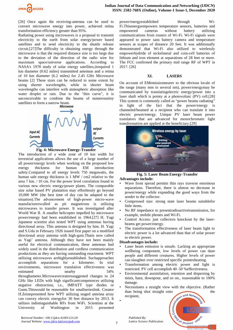
X. MICROWAVES
Energy waves can be made more directional by radioactive
waves. This typically allows long distance to radiate power
with a low frequency of EM
radiation in the micro wave
series.
Indian Journal of Data Communication and Networking (IJDCN)
ISSN: 2582-760X (Online), Volume-1 Issue-1, December 2020
7
Published By:
Lattice Science Publication Retrieval Number: 100.1/ijdcn.A1001121120
Journal Website: www.ijdcn.latticescipub.com
[26] Once again the receiving-antenna can be used to
convert microwave energy into power, achieved retina
transformation efficiency greater than 95%.
Radiating power using microwaves is a proposal to transmit
electricity to the earth from solar energy/power based
satellites and to send electricity to the shuttle release
circuit.[27]The difficulty in obtaining energy through the
microwave is that the required distance size is too large due
to the deviation of the direction of the radio wire for
maximum space/universe applications. According to
NASA's 1978 study of solar energy satellites,itrequired 1
km diameter (0.62 miles) transmitted antennas and a retina
of 10 km diameter (6.2 miles) for 2.45 GHz Microwave
beams [2] These sizes can be reduced to some extent by
using shorter wavelengths, while in shorter beam
wavelengths can interfere with atmospheric absorption like
water droplet or rain. Due to the "thin curve", it is
unconceivable to combine the beams of numeroustiny
satellites to form a narrow beam.
Fig. 4: Microwave Energy-Transfer
The introduction of a wide zone of 10 km width for
terrestrial applications allows the use of a large number of
all power/energy levels when working on the proposed low
energy thickness for human EM introduction
safety.Compared to all energy levels 750 megawatts, the
human safe energy thickness is 1 MW / cm2 relative to the
area 7 km. / 10 cm. For the power level correlation found in
various new electric energy/power plants. The comparable
size solar based PV plantation may effortlessly go beyond
10,000 MW (the best time of day can be adapted to the
situation).The advancement of high-power micro-wave
manufacturerscalled as pit magnetrons is utilizing
microwaves to transfer power. It was investigated after
World War II. A smaller helicopter impelled by microwave
power/energy had been established in 1964.[27] H. Yagi
Japanese scientist also tested WPT using antennas having
directional array. This antenna is designed by him. H. Yagi
and S.Uda in February 1926 issued first paper on a modified
directional array antenna with high-gain.Thatis now called
as Yagi‟ antenna. Although they have not been mainly
useful for electrical communication, these antennas had
widely used in the distribution and cordless communication
productions as they are having outstanding enactment. WPT
utilizing microwaves arehighlyestablished. Suchapproaches
accomplish separations for a kilometer. In trial
environments, microwave translation effectiveness was
estimated nearby 54%
throughameter.Microwavecreatorssuggested changes to 24
GHz like LEDs with high significantcompetences utilizing
negative obstruction, i.e., IMPATT type diodes or
Gunn.Thiswould be reasonable for smallserieslink. Creator
H.Zeinepresented how WPT utilizing staged antenna array
can convey electric energyfor 30 feet distance by 2013. It
utilizes indistinguishable RFs from WiFi. Scientists at the
University of Washington in 2015 presented
power/energyestablished through Wi-
Fi.Thisenergyempowers temperature sensors, batteries and
empowered cameras without battery utilizing
communications from routers of Wi-Fi. Wi-Fi signals were
appeared to power sans battery camera and temperature
sensors at scopes of distance 20 feet. It was additionally
demonstrated that Wi-Fi also utilized to wirelessly
empowerhydride of nickelmetal and coin-cell batteries of
lithium and iron element at separations of 28 feet or more.
The FCC confirmed the primary mid range RF of WPT in
2017. [26]
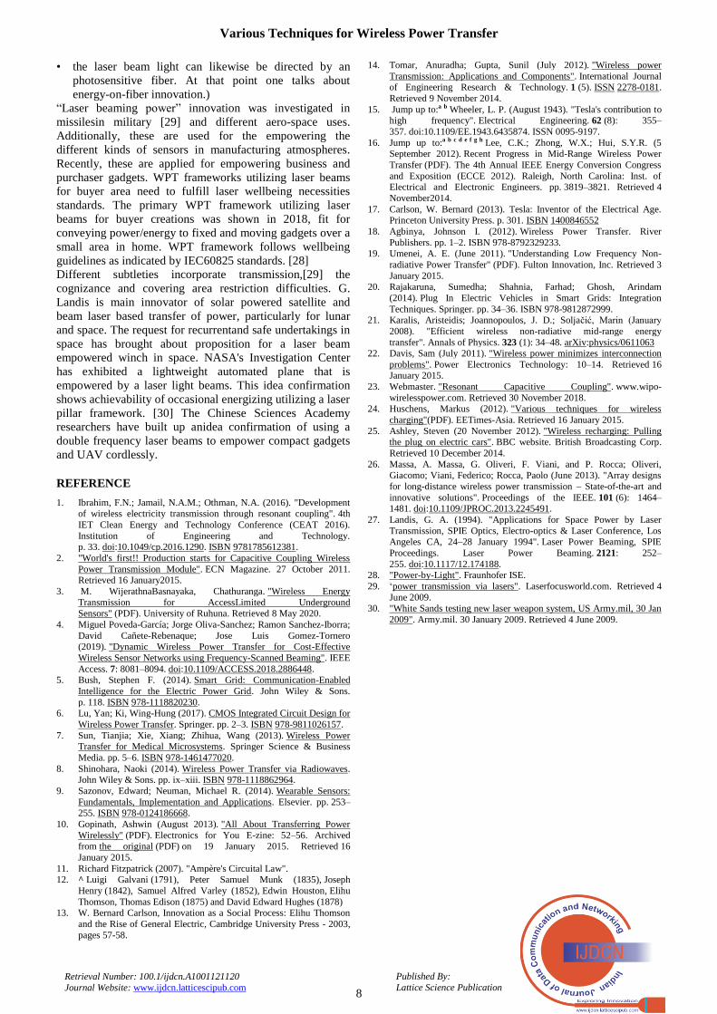
XI. LASERS
On account of EMemissionnearer to the obvious locale of
the range (many mm to several nm), power/energymay be
communicated by translatingelectric energy/power into a
laser shaft which is pointy at a photovoltaic (PV) cell.[28]
This system is commonly called as “power beams radiating”
in light of the fact that the power/energy is
channeled/beamed at a recipient who can translate it into
electric power/energy. Unique PV laser beam power
translators that are advanced for monochromatic light
transformation are applied at the beneficiary.[29]
Fig. 5: Laser Beam Energy-Transfer
Advantages include:
• Wave front spread permits thin rays traverse enormous
separations. Therefore, there is almost no decrease in
power/energy while expanding the good ways from the
sender to the collector.
• Compressed size: strong state laser beams suitablefor
little items.
• No RF impedance to presentradioactivetransmission, for
example, mobile phones and Wi-Fi.
• Control Access: just collectors knockout by the laser-
beams get power/energy.
• The transformation effectiveness of laser beam light to
electric power is a lot advanced than that of solar power
to electric power.
Disadvantages include:
• Laser beam emission is unsafe. Lacking an appropriate
wellbeing component, low levels of power can daze
people and different creatures. Higher levels of power
can slaughter over restricted specific pointreheating.
• Transformation among electric power and light is
restricted. PV cell accomplish 40–50 %effectiveness.
• Environmental assimilation, retention and dispersing by
mists, haze, downpour, and so on., reasonsable to 100%
damage.
• Necessitates a straight view with the objective. (Rather
than being shot straight onto the
recipient,
•
Various Techniques for Wireless Power Transfer
8
Published By:
Lattice Science Publication Retrieval Number: 100.1/ijdcn.A1001121120
Journal Website: www.ijdcn.latticescipub.com
• the laser beam light can likewise be directed by an
photosensitive fiber. At that point one talks about
energy-on-fiber innovation.)
“Laser beaming power” innovation was investigated in
missilesin military [29] and different aero-space uses.
Additionally, these are used for the empowering the
different kinds of sensors in manufacturing atmospheres.
Recently, these are applied for empowering business and
purchaser gadgets. WPT frameworks utilizing laser beams
for buyer area need to fulfill laser wellbeing necessities
standards. The primary WPT framework utilizing laser
beams for buyer creations was shown in 2018, fit for
conveying power/energy to fixed and moving gadgets over a
small area in home. WPT framework follows wellbeing
guidelines as indicated by IEC60825 standards. [28]
Different subtleties incorporate transmission,[29] the
cognizance and covering area restriction difficulties. G.
Landis is main innovator of solar powered satellite and
beam laser based transfer of power, particularly for lunar
and space. The request for recurrentand safe undertakings in
space has brought about proposition for a laser beam
empowered winch in space. NASA's Investigation Center
has exhibited a lightweight automated plane that is
empowered by a laser light beams. This idea confirmation
shows achievability of occasional energizing utilizing a laser
pillar framework. [30] The Chinese Sciences Academy
researchers have built up anidea confirmation of using a
double frequency laser beams to empower compact gadgets
and UAV cordlessly.
REFERENCE
1. Ibrahim, F.N.; Jamail, N.A.M.; Othman, N.A. (2016). "Development of wireless electricity transmission through resonant coupling". 4th
IET Clean Energy and Technology Conference (CEAT 2016).
Institution of Engineering and Technology. p. 33. doi:10.1049/cp.2016.1290. ISBN 9781785612381.
2. "World's first!! Production starts for Capacitive Coupling Wireless
Power Transmission Module". ECN Magazine. 27 October 2011. Retrieved 16 January2015.
3. M. WijerathnaBasnayaka, Chathuranga. "Wireless Energy
Transmission for AccessLimited Underground Sensors" (PDF). University of Ruhuna. Retrieved 8 May 2020.
4. Miguel Poveda-García; Jorge Oliva-Sanchez; Ramon Sanchez-Iborra;
David Cañete-Rebenaque; Jose Luis Gomez-Tornero (2019). "Dynamic Wireless Power Transfer for Cost-Effective
Wireless Sensor Networks using Frequency-Scanned Beaming". IEEE
Access. 7: 8081–8094. doi:10.1109/ACCESS.2018.2886448. 5. Bush, Stephen F. (2014). Smart Grid: Communication-Enabled
Intelligence for the Electric Power Grid. John Wiley & Sons.
p. 118. ISBN 978-1118820230. 6. Lu, Yan; Ki, Wing-Hung (2017). CMOS Integrated Circuit Design for
Wireless Power Transfer. Springer. pp. 2–3. ISBN 978-9811026157.
7. Sun, Tianjia; Xie, Xiang; Zhihua, Wang (2013). Wireless Power Transfer for Medical Microsystems. Springer Science & Business
Media. pp. 5–6. ISBN 978-1461477020.
8. Shinohara, Naoki (2014). Wireless Power Transfer via Radiowaves. John Wiley & Sons. pp. ix–xiii. ISBN 978-1118862964.
9. Sazonov, Edward; Neuman, Michael R. (2014). Wearable Sensors:
Fundamentals, Implementation and Applications. Elsevier. pp. 253–255. ISBN 978-0124186668.
10. Gopinath, Ashwin (August 2013). "All About Transferring Power
Wirelessly" (PDF). Electronics for You E-zine: 52–56. Archived from the original (PDF) on 19 January 2015. Retrieved 16
January 2015.
11. Richard Fitzpatrick (2007). "Ampère's Circuital Law". 12. ^ Luigi Galvani (1791), Peter Samuel Munk (1835), Joseph
Henry (1842), Samuel Alfred Varley (1852), Edwin Houston, Elihu
Thomson, Thomas Edison (1875) and David Edward Hughes (1878) 13. W. Bernard Carlson, Innovation as a Social Process: Elihu Thomson
and the Rise of General Electric, Cambridge University Press - 2003,
pages 57-58.
14. Tomar, Anuradha; Gupta, Sunil (July 2012). "Wireless power
Transmission: Applications and Components". International Journal of Engineering Research & Technology. 1 (5). ISSN 2278-0181.
Retrieved 9 November 2014.
15. Jump up to:a b Wheeler, L. P. (August 1943). "Tesla's contribution to high frequency". Electrical Engineering. 62 (8): 355–
357. doi:10.1109/EE.1943.6435874. ISSN 0095-9197.
16. Jump up to:a b c d e f g h Lee, C.K.; Zhong, W.X.; Hui, S.Y.R. (5 September 2012). Recent Progress in Mid-Range Wireless Power
Transfer (PDF). The 4th Annual IEEE Energy Conversion Congress
and Exposition (ECCE 2012). Raleigh, North Carolina: Inst. of Electrical and Electronic Engineers. pp. 3819–3821. Retrieved 4
November2014.
17. Carlson, W. Bernard (2013). Tesla: Inventor of the Electrical Age. Princeton University Press. p. 301. ISBN 1400846552
18. Agbinya, Johnson I. (2012). Wireless Power Transfer. River
Publishers. pp. 1–2. ISBN 978-8792329233. 19. Umenei, A. E. (June 2011). "Understanding Low Frequency Non-
radiative Power Transfer" (PDF). Fulton Innovation, Inc. Retrieved 3
January 2015.
20. Rajakaruna, Sumedha; Shahnia, Farhad; Ghosh, Arindam
(2014). Plug In Electric Vehicles in Smart Grids: Integration
Techniques. Springer. pp. 34–36. ISBN 978-9812872999. 21. Karalis, Aristeidis; Joannopoulos, J. D.; Soljačić, Marin (January
2008). "Efficient wireless non-radiative mid-range energy
transfer". Annals of Physics. 323 (1): 34–48. arXiv:physics/0611063 22. Davis, Sam (July 2011). "Wireless power minimizes interconnection
problems". Power Electronics Technology: 10–14. Retrieved 16 January 2015.
23. Webmaster. "Resonant Capacitive Coupling". www.wipo-
wirelesspower.com. Retrieved 30 November 2018. 24. Huschens, Markus (2012). "Various techniques for wireless
charging"(PDF). EETimes-Asia. Retrieved 16 January 2015.
25. Ashley, Steven (20 November 2012). "Wireless recharging: Pulling the plug on electric cars". BBC website. British Broadcasting Corp.
Retrieved 10 December 2014.
26. Massa, A. Massa, G. Oliveri, F. Viani, and P. Rocca; Oliveri,
Giacomo; Viani, Federico; Rocca, Paolo (June 2013). "Array designs
for long-distance wireless power transmission – State-of-the-art and
innovative solutions". Proceedings of the IEEE. 101 (6): 1464–1481. doi:10.1109/JPROC.2013.2245491.
27. Landis, G. A. (1994). "Applications for Space Power by Laser
Transmission, SPIE Optics, Electro-optics & Laser Conference, Los Angeles CA, 24–28 January 1994". Laser Power Beaming, SPIE
Proceedings. Laser Power Beaming. 2121: 252–
255. doi:10.1117/12.174188. 28. "Power-by-Light". Fraunhofer ISE.
29. „power transmission via lasers". Laserfocusworld.com. Retrieved 4
June 2009. 30. "White Sands testing new laser weapon system, US Army.mil, 30 Jan
2009". Army.mil. 30 January 2009. Retrieved 4 June 2009.