Embed Size (px)
Citation preview

Page 1 of 48 Wef:
00.00.2011 Indian Railway Specification for Block Proving by Axle
Counter using U FSBI [BPAC] IRS: S-105/2011
Ver-0
lR;eso t;rs
INDIAN RAILWAY STANDARD SPECIFICATION
FOR
BLOCK PROVING WITH AXLE COUNTER USING UFSBI
(BPAC)
IRS: S-105/2011 Ver-0
SIGNAL DIRECTORATE RESEARCH DESIGN& STANDARDS ORGANISATION
LUCKNOW-226011
Page 2 of 48 Wef:
00.00.2011 Indian Railway Specification for Block Proving by Axle
Counter using U FSBI [BPAC] IRS: S-105/2011
Ver-0
DOCUMENT DATA SHEET Designation IRS S: 105/2011
Version 0
Title of Document Indian Railway Standard Specification for Block Proving with Axle Counter using UFSBI
Author: Akhilesh Kr. Yadav Designation: Director/Signal/RDSO
Approved by : Shri Mahesh Mangal Designation: Sr. Executive Director/Signal, RDSO
Abstract: This document defines specification for Block Proving with Axle Counter using UFSBI
Page 3 of 48 Wef:
00.00.2011 Indian Railway Specification for Block Proving by Axle
Counter using U FSBI [BPAC] IRS: S-105/2011
Ver-0
DOCUMENT CONTROL SHEET
NAME ORGANISATION FUNCTION LEVEL
Akhilesh Kr. Yadav
RDSO
Member
Prepare
Shri Mahesh Mangal
RDSO
-
Approve

Page 4 of 48 Wef:
00.00.2011 Indian Railway Specification for Block Proving by Axle
Counter using U FSBI [BPAC] IRS: S-105/2011
Ver-0
AMENDMENTS
Version Chapter/Annexure
Amendment
Effective date
0
-
First issue
00.00.2011

Page 5 of 48 Wef:
00.00.2011 Indian Railway Specification for Block Proving by Axle
Counter using U FSBI [BPAC] IRS: S-105/2011
Ver-0
Table of Content
Page No.
0 Foreword 6
1.0 Scope 7
2.0 Terminology 7
3.0 Requirements 7-15
4.0 Indications on Block Panel 15-19
5.0 Brief system description & working 19
6.0 Principle of working 20
7.0 Description of block panel for Single Line 20-22
8.0 Description of block panel for Double Line 22-23
9.0 Method of signalling Trains from block station to block station for single
line
23-33
10.0 Method of signalling Trains from block station to block station for double
line
33-44
11.0 Method of “line clear cancellation” both for single & double lines 44-45
12.0 Design Criteria 45
13.0 System requirements 45
14.0 Information to be given by supplier 45
15.0 Information to be given by purchaser 45
16.0 Documentation 45-46
17.0 Acceptance criteria 46
18.0 Inspection 46
19.0 Test procedure 46
20.0 Marking 46
21.0 Packing 47
22.0 Warranty 47

Page 6 of 48 Wef:
00.00.2011 Indian Railway Specification for Block Proving by Axle
Counter using U FSBI [BPAC] IRS: S-105/2011
Ver-0
GOVERNMENT OF INDIA MINISTRY OF RAILWAYS
(RAILWAY BOARD)
INDIAN RAILWAY STANDARD SPECIFICATION
FOR BLOCK PROVING WITH AXLE COUNTER USING
UFSBI 0. FOREWORD 0.1 This specification is issued under the fixed Serial No. RDSO/SPN/188/2004 followed by the year
of adoption as standard or in case of revision the year of latest revision. 0.2 This specification requires reference to the following Indian Railway Standards (IRS) and Indian
Standards (IS) and RDSO/SPN.
IRS: S23 Indian Railway Standard specification for electrical and electronic based signaling and interlocking equipment
RDSO/SPN/144 Safety and reliability of electronic signaling equipment RDSO/SPN/177 Specification of Single section Digital Axle Counter RDSO/SPN 147 Specification of universal Fail Safe Block Interface. RDSO SPN 165 Specification of SMPS based Integrated Power Supply System (IPS) for
S&T Installation of Indian Railways. IRS: S-76 Specification of Cable Signaling Indoor for Signaling Installations IRS S-86 Specification for Battery Charger for Signalling Installations IRS S- 21 Specification of EKT IRS: S 61 Fail Safe Electronic Timer BRS: 930A & 931A Relays ‘Q’ Series Neutral Line. IS: 7088 Recommended practice for anodizing aluminum and its alloys TC 30 Specification for Jelly filled Quad cable IS: 513 Cold rolled low carbon steel sheets and strips - Specification IS: 7569 Specification for cast acrylic sheets for use in luminaries IS: 2629 Recommended practice for hot-dip galvanising of iron and steel IS: 694 Specification for PVC insulated cable IS: 1573 Specification for electroplated coatings of zinc on iron and steel IS: 2147-1962 Degree of protection provided by enclosures for low-voltage switchgear
and control gear IS: 5-1994 Colors for ready mixed paints and enamels IS: 814 Covered electrodes for manual metal arc welding of carbon and carbon
manganese steel - Specification IEC 947-7-1 International standard on terminal blocks for copper conductors.
0.3 Whenever in this specification, any of the above mentioned specification is referred by number
only, without mentioning the year of issue, the latest issue of that specification is implied, otherwise the particular issue referred to is meant.
0.4 This specification is intended to cover the technical provisions and it does not include all the
necessary provisions of a contract.

Page 7 of 48 Wef:
00.00.2011 Indian Railway Specification for Block Proving by Axle
Counter using U FSBI [BPAC] IRS: S-105/2011
Ver-0
1.0 SCOPE 1.1 This specification covers the general and technical requirements of Block Proving with Axle
Counter using UFSBI to be used in Indian Railways for block working. 1.2 The specification covers integrated type block panel but not covers domino type panels. The body
of panel should be fabricated from 18 SWG CRC MS sheet conforming to specification IS- 513 grade D.
2.0 Terminology:
The terminology as given in IRS-S-23 shall be applicable. In additions to the other terms which are referred in the specification are given below-
2.1 Rated voltage : The nominal voltage at which the Block System is designed to operate.
2.2 Rated Current : The nominal current consumption of Block System.
3.0 Requirements:
The Block Proving system will require the following sub systems for its working as per scheme
depicted in RDSO Drg.No. RDSO/S/32017 Sheet No.1 for Double Line and RDSO/S/32019 Sheet No. 1 for Single Line:
(i) Block Panel (ii) Universal Fail Safe Block Inter face (iii) Single Section Digital Axle Counter (iv) Block Telephone (v) Telecom cable, voice/ data channels provided over optical fiber or microwave system
using proper multiplexer. (vi) Battery Set (vii) Battery Charger / IPS module (viii) Relay rack with relays
3.1 Block Panel
Mechanical & Physical requirements:
3.1.1 Panel shall suit to RDSO’s Drg No. RDSO /S 32017 Sheet no. 2 & 3 for double line & RDSO /S 32019 Sheet no. 2 & 3 for single line. Body of panel to be made of CRC MS sheet of thickness not less than 18 SWG conforming to specification IS- 513 grade D. Panel shall be drip proof and shall be protected against ingress of water. Sufficient strength, rigidity and stability required shall be ensured.
3.1.2 Body of the cabinet shall be free from dents, undulations, surface irregularities etc. 3.1.3 MS sheets shall be welded together and to its structure properly, if required, ensuring no welding
defects. 3.1.4 Standard fasteners to relevant specification with zinc plating / Nickel plating shall be used for
fastening. 3.1.5 Riveting, wherever necessary, to be carried out properly as per standard engineering practice.

Page 8 of 48 Wef:
00.00.2011 Indian Railway Specification for Block Proving by Axle
Counter using U FSBI [BPAC] IRS: S-105/2011
Ver-0
3.1.6 Provision shall be made for locking the back door. 3.1.7 The terminals used in the panel shall be non-disconnecting type polymer (6.6 Polyamide/nylon
6.6/Malamine) based terminals of Phoenix/ Wago make with DIN rail mounting arrangements. 3.1.8 Surface of the panel except faceplate shall be treated with chromate Primer followed by powder
coating in Siemens gray color thickness 70-80 microns Texture finish. 3.1.9 The faceplate will be made of 16 SWG MS, with an anodized aluminum faceplate above it. 3.1.10 Faceplate shall be free from all surface irregularities such as dents, tool marks, undulations etc. 3.1.11 Faceplate shall be covered with colorless (transparent) acrylic sheet of 4 mm thickness +0.5mm
as per IS: 7569. Acrylic sheet should not have any scratch, air bubbles, foreign material or any other marks.
3.1.12 Transparent acrylic sheet shall be fixed on top of the faceplate by a removable frame of minimum
3 mm thickness. 3.1.13 Panel shall have holes in the base suitable to fix the panel on the table. 3.1.14 All metallic nuts, bolts and washers used in fabrication of the panel shall be suitably zinc coated
as per IS: 1573 to ensure rust proof working for entire life of the panel. 3.1.15 Metal arc welding, wherever used, shall be done with welding electrodes as per IS: 814. 3.1.16 Panel shall conform to IP 54 class of protection as specified in table 1 of IS: 2147 3.1.17 Panel shall be provided with back covers. Back covers shall be easily opened to facilitate access
to the internal wiring, termination etc. and shall be provided with double lock and sealing facility. 3.1.18 Legends shall be painted legibly on the panel faceplate as specified in the drawing. 3.1.19 Faceplate shall be firmly fixed on the cabinet using fasteners. 3.1.20 Station Master’s (SM’s) key lock shall be provided at top of the faceplate. The key shall normally
remain locked in turned position. 3.1.21 Small metal parts e.g. nuts, bolts, washers and such other out side fittings shall be suitably plated. 3.1.22 All component elements shall be rigidly fixed to withstand normal shock and vibration. 3.1.23 The panel shall be wired using 16/. 02 wire conforming to specification IRS: S-76. 3.1.24 Individual termination shall be marked with a unique number for easy identification. 3.1.25 Wiring inside the panel shall be properly bunched using cable ties and supported. 3.1.26 Any break or short circuit in wires shall not cause a wrong indication or operation of counter or
pick-up of a wrong relay. 3.1.27 A laminated copy of wiring diagram and termination details of the panel portion shall be pasted
inside back cover of the panel.

Page 9 of 48 Wef:
00.00.2011 Indian Railway Specification for Block Proving by Axle
Counter using U FSBI [BPAC] IRS: S-105/2011
Ver-0
3.1.28 Block panel should pass insulation resistance test before and after applied high voltage test as per Cl. 9.5 & 9.6 of RDSO/SPN/144.
3.1.29 Block Panel should be able to function at a distance of 50 M. from the Relay Rack. If the
distance from block panel to relay rack is more than 50M, 1.5 sq mm out door signaling cable shall be used.
3.1.30 Parts of Block Panel: 3.1.30.1. Push Buttons: The push buttons will be of Siemens or L&T (ESBEE) make as detailed below: 3.1.30.1.1 Push Button Actuator:
Type: HD 55C1 (Red) or HD 55C2 (Green) or HD 55C3 (Black) & HD 55C4 (Yellow) 3.1. 30.1.2 Contact Element for Push Button and key actuator:
Type- HC61A2 (1NO), HC61B2 (1NC) 3.1.30.2 Keys & Switches: The switches and keys shall be of different make.
The LCB key is L&T make (ESBEE brand) with catalog number HK85C3 for Key Actuator & HC61A2 (1 NO) / HC61B2 (1 NC) for elements. The SM’s key is Siemens make with catalog number CES1 & for actuator 3SB04 00-0B for element.
3.1. 30.3 LEDs:
(i) LED’s used shall be high intensity super bright water clear type of Agilent / Nichia make and must have 5 mm diameter and clear body/lens.
(ii) LEDs shall be with viewing angle of 15°. An illuminated LED should be visible
from minimum 3 meters in clear daylight. Part no. and manufacturer’s data sheet of LEDs used shall be supplied with the panel.
3.1.30.4 Electromagnetic Impulse Counter:
Electro magnetic impulse counter shall be 6 Digit, 10 impulse per second minimum, 24V DC non-resettable type, Shinmei make, Type ECT-6A or Keltron Make: Type EM010 or Fritz Kubler: Type W16.20
3.1.30.5 Buzzers:
Separate buzzers with different audio frequencies, working at 24 volts (+20% -10%) DC for audio alarm should be provided to register the BELL CODE sent by other end SM & to register the occupation and clearance of each Block Section. The buzzer for receive line shall be intermittent and for dispatch line shall be continuous type. Provision to mute the audio alarm through pressing an acknowledgement push button shall be provided. Block buzzer shall work through block telephone line.

Page 10 of 48
Wef: 00.00.2011
Indian Railway Specification for Block Proving by Axle Counter using U FSBI [BPAC]
IRS: S-105/2011
Ver-0
3.2 UNIVERSAL FAIL SAFE BLOCK INTERFACE:
Universal Fail Safe Block Interface (UFSBI) required to interface the conventional block instruments over Telecom cable, voice/ data channels of any media like OFC & Digital Radio using proper multiplexer.
3.3 Single Section Digital Axle Counter:
Single Section Digital Axle Counter consists of a pair of axle detectors connected together by a transmission medium in VF range. It is capable of counting axles; count comparison, supervision, relay drive and transmission of counts and health of axle detector. Digital Axle Counter track relay output is available at both ends of the track section.
3.4 Block Telephone: 3.4.1 For speech communication with SM at other end of Block Section. 3.4.2 Separate block telephone shall be provided for every block section. 3.4.3 Block Panel to have provision for hanging block telephone as shown in Drg. No. RDSO /S 32017
Sheet no. 3 for double line & RDSO /S 32019 Sheet no. 3 for single line. 3.5 Quad Cable Or Voice channel:
Railways shall provide 4 pair copper conductors or 3 voice channels in OFC for single line block working and 5 pair copper conductor or 4 voice channels in OFC for double line block working from station to station. Cable shall be as per specification IRS:TC 30.
3.6 Battery Set: (Railways shall provide the battery set) 3.6.1 Block Proving with Axle Counter system comprising of Block Panel, Universal Fail Safe Block
Interface, & relays shall work on 24 V D.C. with a maximum current consumption of 5A. 3.6.2 Separate power supply shall be provided for Digital Axle Counter. 3.6.3 Separate power supply shall be provided for Block Telephone. 3.7 Charger / Module of IPS: 3.7.1 The charger should be as per IRS S-86 to cater 5A/24V DC load. 3.7.2 The IPS module should be as per RDSO SPN 165 to cater 5A/24V DC load. 3.8 Relay Rack & Signaling Relays: 3.8.1 Number of relays used for Double Line Block working is 29 nos. and for Single Line Block
working is 31 nos. All the relays used as per the circuit diagram shall be of RDSO approved make. Relays used as repeater of external relays shall be of 1000 ohms. Relay Rack can be separate or it can be in the same cabinet of UFSBI. The Electronic Fail Safe Timer (IRS: S 61) shall be micro controller based only.
Alternatively, to minimize the number of relays, 2 out of 2 digital hardware logic (in compliance with CENELEC SIL-4 standard) based on reliable PLD / CPLD of reputed make like LATTICE / ALTERA / XYLINX, may be used to implement the Block Interlocking Logic with same functionality without any change in hardware / software or

Page 11 of 48
Wef: 00.00.2011
Indian Railway Specification for Block Proving by Axle Counter using U FSBI [BPAC]
IRS: S-105/2011
Ver-0
interfacing circuit of UFSBI (as per RDSO/SPN/147/2005). The hardware logic module for Single Line and Double Line should be distinctly different and it shall not be possible to inter-change the modules. UFSBI should retain its functionality of Inter-station Block communication as per RDSO/SPN/188/2004.
3.8.2 NOMENCLATURE OF RELAYS FOR SINGLE LINE WITH UFSBI AS PER DRAWING
NUMBER- RDSO/S-32020. The nomenclature of various relays in the relay rack used at each station is given below - RELAY TYPE and
NORMAL STATUS
DESCRIPTION
3.8.2.1 TGTR QL1, 11F.4B DROP
TRAIN GOING TO Relay. Operates to pick up on receipt of LINE CLEAR at train sending station. Normalises, when station at the other end sets to Line closed after train arrival or cancellation of LINE CLEAR.
3.8.2.2 TCFR QL1, 11F.4B DROP
TRAIN COMING FROM Relay. Operates to pick up on receipt of LINE CLEAR enquiry from train sending station. Normalises after complete train arrival or cancellation of LINE CLEAR.
3.8.2.3 ASCR
QN1, 8F.8B DROP
Advance Starter Signal Control relay. Picks up, when LINE CLEAR is available and necessary controls are reversed by SM. Drops in any of the under-mentioned cases: a) Entry of train in Block Section b) Withdrawal of any SM control
3.8.2.4 TGTXR QN1, 8F.8B DROP
TRAIN GOING TO code Relay. Picks up at train sending station presses buttons for LINE CLEAR enquiry. Drops when train sending station releases buttons for LINE CLEAR enquiry.
3.8.2.5 TCFXR QN1, 8F.8B DROP
TRAIN COMING FROM code Receive Relay. Picks up on receipt of LINE CLEAR enquiry from train sending station. Drops when station at other end releases buttons for LINE CLEAR enquiry.
3.8.2.6 TGTYR QN1, 8F.8B DROP
TRAIN GOING TO code Receive Relay. Picks up on receipt of LINE CLEAR at train sending station. Drops in any of the under-mentioned cases: a) Entry of train in Block Section b) Cancellation
3.8.2.7 120 JPR QN1, 8F.8B DROP
Timer mature repeater Relay. Picks up on maturity of Timer for cancellation. Drops when block status set to Line Closed.
3.8.2.8 BPNR QN1, 8F.8B DROP
Bell push button relay. Picks up on pressing of BELL push button else drops.
3.8.2.9 TGTNR QN1, 8F.8B DROP
TRAIN GOING TO button Relay. Picks up on pressing of TRAIN GOING TO push button else drops.

Page 12 of 48
Wef: 00.00.2011
Indian Railway Specification for Block Proving by Axle Counter using U FSBI [BPAC]
IRS: S-105/2011
Ver-0
3.8.2.10 CNR QN1, 8F.8B DROP
CANCEL button relay. Picks up on pressing of CANCEL push button else drops.
3.8.2.11 FR1 QN1, 8F.8B DROP
Flash controller relay No. 1.
3.8.2.12 FR2 QN1, 8F.8B DROP
Flash controller relay No. 2.
3.8.2.13 TAR1 QNA1, 8F.8B DROP
Train Arrival First Relay. Picks up when control on Reception Signal is Reverse and HSAT occupied by train and HSBT clear. Drops when HSAT clear with a delay.
3.8.2.14 TAR2 QN1, 8F.8B DROP
Train Arrival Second Relay. Picks up when control on Reception Signal is Reverse and HSAT clear and HSBT occupied by train. Drops when block status set to Line Closed.
3.8.2.15 CAR QN1, 8F.8B DROP
CANCEL relay. Picks up at Train receiving station on initiation of cancellation provided all controls pertaining to Advance Starter and Reception Signal/Signals and signals controlled by them are at Normal at both the stations.
3.8.2.16 BTSR QN1, 8F.8B PICK UP
Block Track Stick Relay. Picks up when Block status is LINE CLOSED and Block track is clear. Drops in any of the under-mentioned cases: a) Entry of train in Block Section b) Cancellation
3.8.2.17 AZTR
QNA1, 8F.8B PICK UP
Block Section track Relay of Dispatch Line. Drops in the under mentioned case:
(a) Entry of train in block section. (b) Failure of axle counter.
3.8.2.18 TGTZR QN1, 8F.8B PICK UP
Advance Starter Signal Normal Checking Repeater Relay. Picks up to repeat [D] ASGNCR at train receiving station after arrival of train or after a Line Clear cancellation has been initiated, else drops.
3.8.2.19 120 EJ Electronic Time delay unit (Fail Safe)
Timer unit for cancellation time of 120 seconds.
3.8.2.20 HS ATPR
QNA1, 8F.8B PICK UP
First track for direction proving repeater relay. Picks up when HSAT track circuit is vacant else drop.
3.8.2.21 HS BTPR
QNA1, 8F.8B PICK UP
Second track for direction proving repeater relay. Picks up when HSBT track circuit is vacant else drop.
3.8.2.22 AS GNCR
QNA1, 8F.8B PICK UP
Advance Starter Signal Normal checking Relay. Picks up when Advance Starter Signal (LSS) and all its controls are at ON/Normal, else drops.
3.8.2.23 HS GNCR
QNA1, 8F.8B PICK UP
Reception Signal Normal Checking Relay. Picks up when Reception signal/signals and all its controls are at ON/Normal, else drops.
3.8.2.24 TCFCR QN1, 8F.8B PICK UP
TRAIN COMING FROM CANCEL relay. Picks up at receiving station when CANCEL CO-OP button is pressed at sending station else drops.
3.8.2.25 TCFZR QN1, 8F.8B PICK UP
TRAIN COMING FROM normal proving relay. Picks up at receiving station when TCFR drops else drops.

Page 13 of 48
Wef: 00.00.2011
Indian Railway Specification for Block Proving by Axle Counter using U FSBI [BPAC]
IRS: S-105/2011
Ver-0
3.8.2.26 TGTPR QN1, 8F.8B PICK UP
TRAIN GOING TO normal proving relay. Picks up at sending station when TGTR drops else drops.
3.8.2.27 SHKR QN1, 8F.8B PICK UP
Shunt Key indicating relay. Picks up when key of EKT is ‘IN’ & shunt Release key is OUT, else drop.
3.8.2.28 AS
GNCPR QN1, 8F.8B PICK UP
Advance Starter Signal Normal checking (for other station) Relay. Picks up when Advance Starter Signal and all its controls are at Normal at the other station, else drops.
3.8.2.29 BIPR1 QN1, 8F.8B TOGGLE
UFSBI health check relay.
3.8.2.30 BIPR2 QN1, 8F.8B TOGGLE
UFSBI health check relay.
3.8.2.31 BLR QN1, 8F.8B DROP
BELL RELAY Pick up when other station presses the Bell button
Note: For use with MUX-Combiner please refer Block Working Manual & Drawing Number RDSO/S-
32016. 3.8.3 NOMENCLATURE OF RELAYS FOR DOUBLE LINE WITH UFSBI AS PER DRAWING
NUMBER- RDSO/S-32018. The nomenclature of various relays in the relay rack used at each station is given below: RELAY TYPE AND
NORMAL STATUS
DESCRIPTION
3.8.3.1 TGTR QL1, 11F.4B DROP
TRAIN GOING TO Relay. Operates to pick up on receipt of LINE CLEAR at train sending station. Normalises, when station in advance sets to Line closed after train arrival or cancellation of LINE CLEAR.
3.8.3.2 TCFR QL1, 11F.4B DROP
TRAIN COMING FROM Relay. Operates to pick up on receipt of LINE CLEAR enquiry from train sending station. Normalises after complete train arrival or cancellation of LINE CLEAR.
3.8.3.3 ASCR
QN1, 8F.8B DROP
Advance starter signal control relay Picks up, when LINE CLEAR is available and necessary controls are reversed by SM. Drops in any of the under-mentioned cases: a) Entry of train in Block Section. b) Withdrawal of any SM control.
3.8.3.4 TGTXR QN1,8F.8B DROP
TRAIN GOING TO code Relay. Picks up at train sending station pressing of buttons for LINE CLEAR enquiry. Drops when train sending station releases buttons for LINE CLEAR enquiry or picking up of TGTR which ever is earlier.
3.8.3.5 TGTYR QN1, 8F.8B DROP
TRAIN GOING TO code Receive Relay. Picks up on receipt of LINE CLEAR at train sending station Drops in any of the under-mentioned cases: a) Entry of train in Block Section. b) Cancellation of Line Clear.

Page 14 of 48
Wef: 00.00.2011
Indian Railway Specification for Block Proving by Axle Counter using U FSBI [BPAC]
IRS: S-105/2011
Ver-0
3.8.3.6 120 JPR QN1, 8F.8B DROP
Timer mature repeater Relay. Picks up on maturity of Timer for cancellation. Drops when block status set to Line Closed.
3.8.3.7 BPNR QN1, 8F.8B DROP
Bell push button relay. Picks up on pressing of BELL push button with SM’s Key IN, else drops.
3.8.3.8 TGTNR QN1, 8F.8B DROP
TRAIN GOING TO button Relay. Picks up on pressing of TRAIN GOING TO push button else drops.
3.8.3.9 CNR QN1, 8F.8B DROP
CANCEL button relay. Picks up on pressing of CANCEL push button else drops.
3.8.3.10 FR1 QN1, 8F.8B DROP
Flash controller relay No. 1.
3.8.3.11 FR2 QN1, 8F.8B DROP
Flash controller relay No. 2.
3.8.3.12 TAR1 QNA1, 8F.8B DROP
Train Arrival First Relay. Picks up when control on Reception Signal is Reverse and HS AT occupied by train and HS BT clear. Drops when AT clear with a delay.
3.8.3.13 TAR2 QN1, 8F.8B DROP
Train Arrival Second Relay. Picks up when control on Reception Signal is Reverse and HS AT clear and HS BT occupied by train. Drops when block status set to Line Closed.
3.8.3.14 CAR QN1, 8F.8B DROP
CANCEL relay. Picks up at Train receiving station on initiation of cancellation provided all controls pertaining to Advance Starter and Reception Signal/Signals and signals controlled by them are at Normal at both the stations.
3.8.3.15 BTSR QN1, 8F.8B PICK UP
Block Track Stick Relay. Picks up when Block status is LINE CLOSED and Block track is clear. Drops in any of the under-mentioned cases: a) Entry of train in Block Section. b) Cancellation OF Line Clear.
3.8.3.16 (R ) AZTR
QNA1, 8F.8B PICK UP
Block Section track Relay of receive line. Drops in the under mentioned cases:
(a) Entry of train in block section, or (b) Axle Counter failure.
3.8.3.17 [D] AZTR
QNA1, 8F.8B PICK UP
Block Section track Relay of dispatch line. Drops in the under mentioned cases:
(a) Entry of train in block section, or (b) Axle Counter failure
3.8.3.18 TGTZR QN1, 8F.8B PICK UP
Advance Starter Signal Normal Checking Repeater Relay. Picks up to repeat Line Closed condition at train receiving station after arrival of train or after a Line Clear cancellation has been initiated, else drops.
3.8.3.19 TCFXR QN1, 8F.8B DROP
TRAIN COMING FROM code Receive Relay. Picks up on receipt of LINE CLEAR enquiry from train sending station. Drops when station in rear releases buttons for LINE CLEAR enquiry or TGTR pick up which ever is earlier.
3.8.3.20 120 EJ Electronic Time delay
Timer unit for cancellation time of 120 seconds.

Page 15 of 48
Wef: 00.00.2011
Indian Railway Specification for Block Proving by Axle Counter using U FSBI [BPAC]
IRS: S-105/2011
Ver-0
unit (Fail Safe)
3.8.3.21 HS ATPR
QNA1, 8F.8B PICK UP
First track for direction proving repeater relay. Picks up when HSAT track circuit is vacant else drop.
3.8.3.22 HS BTPR
QNA1, 8F.8B PICK UP
Second track for direction proving repeater relay. Picks up when HS BT track circuit is vacant else drop.
3.8.3.23 AS GNCR
QNA1, 8F.8B PICK UP
Advance Starter Signal Normal checking Relay. Picks up when Advance Starter Signal and all its controls are at Normal, else drops.
3.8.3.24 HS GNCR
QNA1, 8F.8B PICK UP
Reception Signal Normal Checking Relay Picks up when Reception signal/signals and all its controls are at Normal, else drops.
3.8.3.25 AS GNCPR
QN1, 8F.8B PICK UP
Advance Starter Signal Normal checking (for other station) Relay Picks up when Advance Starter Signal and all its controls are at Normal at the other station, else drops.
3.8.3.26 BIPR1 QN1, 8F.8B TOGGLE
UFSBI health check relay.
3.8.3.27 BIPR2 QN1, 8F.8B TOGGLE
UFSBI health check relay.
3.8.3.28 TCFCR QN1, 8F.8B PICK UP
TRAIN COMING FROM CANCEL relay. Picks up at receiving station when CANCEL CO OP button is pressed at sending station else drops.
3.8.3.29 BLR QN1, 8F.8B DROP
BELL RELAY Pick up when other station presses the Bell button
Note: For use with MUX-Combiner please refer Block Working Manual & Drawing Number RDSO/S-
32012.(Delete) 3.8.4 Wiring of Relay Rack: 3.8.4.1 The relay rack shall be wired using 16/.02 wire conforming to specification IRS: S-76 / 89
(latest). 3.8.4.2 Every wire should be terminated properly. Termination of wires shall be done on non-
disconnecting type terminals of Phoenix/Wago make with DIN rail mounting arrangements. 3.8.4.3 Individual termination shall be marked with a unique number for easy identification. 3.8.4.4 Wiring of relay rack shall be properly bunched using cable ties and supported. 3.8.4.5 A laminated copy of wiring diagrams and termination details shall be provided along with supply. 4.0 Indications on Block Panel: 4.1 SM’s Block Panel for Single Line is provided with following illuminated indications: 4.1.1 LINE CLOSED
Indication Circular indication in between the directional arrowhead. Mentioned in 4.1.2 & 4.1.3.
YELLOW To indicate Block Section free from vehicles and LINE CLEAR not granted /received at train receiving / train sending station respectively.

Page 16 of 48
Wef: 00.00.2011
Indian Railway Specification for Block Proving by Axle Counter using U FSBI [BPAC]
IRS: S-105/2011
Ver-0
4.1.2 TRAIN COMING FROM Indication
In a directional arrowhead pointing downward for incoming traffic towards station.
GREEN To indicate LINE CLEAR granted, when TRAIN GOING TO Button and BELL button have been pressed at sending station and the conditions for the granting of LINE CLEAR at receiving station have been complied with and a rectangular indication named TCF lights up GREEN.
RED To indicate TRAIN ON LINE on entry of incoming train on LINE CLEAR and a rectangular indication named TOL lights up RED.
FLASHING GREEN
To indicate: a) Block section clear after arrival of train, but associated Signals and their controls not normal at either station. b) Cancellation of LINE CLEAR before entry of train in Block Section. c) Block section clear after arrival of train, associated signals and their controls at normal at both stations but after unintentional insertion of Shunt Release Key IN when the train was in section.
4.1.3 TRAIN GOING TO Indication
In a directional arrowhead pointing upward for outgoing traffic away from station at train sending station
GREEN To indicate LINE CLEAR received when TRAIN GOING TO button and BELL button have been pressed on Block Panel of train sending station and the condition for taking the LINE CLEAR have been complied with at both stations and a rectangular indication named TGT lights up GREEN.
RED To indicate TRAIN ON LINE on entry of outgoing train on LINE CLEAR and a rectangular indication named TOL lights up RED.
FLASHING GREEN
To indicate: a) Block Section clear after arrival of train at other station, but associated signals and their controls not normal at either or both stations i.e. SNK off or Shunt key indication ‘RED’. b) LINE CLEAR cancelled before entry of train in block section.
4.1.4 Cancel CO-OP indication YELLOW
Indication to indicate co-operation extended by station at other end for cancellation of line clear by pressing Cancel Cooperation button.
4.1.5 CANCEL indication
Circular LED.
FLASHING YELLOW
To indicate progress of LINE CLEAR cancellation timer of 120 seconds. The indication lights up on pressing of CANCEL along With BELL button, when TRAIN COMING FROM is displaying FLASHING GREEN indication.

Page 17 of 48
Wef: 00.00.2011
Indian Railway Specification for Block Proving by Axle Counter using U FSBI [BPAC]
IRS: S-105/2011
Ver-0
4.1.6 SNK Indications One such indication is provided.
SNK YELLOW
i) Provided near TRAIN GOING TO directional arrowhead to Indicate LAST STOP SIGNAL, Reception signal(s) and their controls at ON/ Normal.
4.1.7 SNOEK (SNK other end) YELLOW
i) Provided near TRAIN COMING FROM directional arrowhead to Indicate the following:
(a) LAST STOP SIGNAL and its controls at station at other end are at ON/ Normal.
(b) Shunt Key of EKT at other end station is ‘IN’.
4.1.8 Last Stop Signal (LSS) Indications
Circular in monogram of signal.
RED
To indicate Last Stop Signal is at ‘ON’.
GREEN
To indicate Last Stop Signal is at ‘OFF’.
4.1.9 LINE FREE Indication GREEN
To indicate Block Section is clear of vehicles.
LINE OCCUPIED Indication RED
To indicate Block Section is occupied.
4.1.10 ACKN indication A Indication near ACKN button.
YELLOW To indicate SECTION buzzer ON status.
4.1.11 SM KEY `IN' indication
Indication near SM KEY.
GREEN To indicate SM key “IN’.
4.1.12 SHUNT KEY indication
GREEN -To indicate SHUNT KEY OF EKT IS “IN”. RED- To indicate SHUNT KEY OF EKT IS “OUT”.
4.1.13 UFSBI/MUX OK indication
Glows GREEN when MUX is OK otherwise Extinguished.
4.1.14 UFSBI/MUX FAIL indication
Glows RED when MUX goes into a failure mode otherwise Extinguished.
4.1.15 Communication LINK FAIL indication
Glows steady YELLOW when LINK FAILS otherwise flickering.

Page 18 of 48
Wef: 00.00.2011
Indian Railway Specification for Block Proving by Axle Counter using U FSBI [BPAC]
IRS: S-105/2011
Ver-0
4.2 SM’s Block Panel for Double Line is provided with following illuminated indications 4.2.1 LINE CLOSED
Indication Circular indications (Two Numbers) in between the directional arrowhead.
YELLOW To indicate Block Section free from vehicles and LINE CLEAR not granted /received at train receiving / train sending station respectively.
4.2.2 TRAIN COMING FROM Indication
In a directional arrowhead pointing downward for incoming traffic towards station at train receiving station
GREEN To indicate LINE CLEAR granted, when TRAIN GOING TO Button and BELL button have been pressed at sending station and the conditions for the granting of LINE CLEAR at receiving station have been complied with and a rectangular indication named TCF lights up GREEN.
RED To indicate TRAIN ON LINE on entry of incoming train on LINE CLEAR.
FLASHING GREEN
To indicate: a) Block section clear after arrival of train, but associated
Signals and their controls not normal at either of station or LCB Key is OUT.
b) Cancellation of LINE CLEAR before entry of train in
Block Section.
4.2.3 TRAIN GOING TO Indication
In an arrowhead pointing upward for outgoing traffic away from station at train sending station and a rectangular indication named TGT.
GREEN To indicate LINE CLEAR received when TRAIN GOING TO button and BELL button have been pressed on Block Panel of train sending station and the condition for taking the LINE CLEAR have been complied with at both stations and a rectangular indication named TGT lights up GREEN.
RED To indicate TRAIN ON LINE on entry of outgoing train on LINE CLEAR. and a rectangular indication named TOL lights up RED
FLASHING GREEN
To indicate: a) Block Section clear after arrival of train at other station, but associated signals and their controls not normal at either or both stations or LCB Key is OUT at receiving station. b) LINE CLEAR cancelled before entry of train in block section.
4.2.4 Cancel CO-OP indication YELLOW
Indication to indicate co-operation extended by station at other end for cancellation of line clear by pressing Cancel Cooperation button.

Page 19 of 48
Wef: 00.00.2011
Indian Railway Specification for Block Proving by Axle Counter using U FSBI [BPAC]
IRS: S-105/2011
Ver-0
4.2.5 CANCEL indication
Circular LED.
FLASHING YELLOW
To indicate progress of LINE CLEAR cancellation timer of 120 seconds. The indication lights up on pressing of CANCEL Button along With BELL button, when TRAIN COMING FROM is displaying FLASHING GREEN indication.
4.2.6 SNK Indications Two such indications are provided.
SNK YELLOW
i) SNK (D): Yellow provided near TRAIN GOING TO directional arrowhead to Indicate LAST STOP SIGNAL and its controls at ON/ Normal.
ii) SNK (R): Yellow provided near TRAIN COMING FROM directional arrowhead to Indicate reception signal (s) & its controls at ON/ Normal
4.2.7 SNOEK (SNK other end) YELLOW
i) Provided near TRAIN COMING FROM directional arrowhead to Indicate LAST STOP SIGNAL and its controls at station in rear are at ON/ Normal.
4.2.8 Last Stop Signal (LSS) Indications
Circular in monogram of signal.
RED
To indicate Last Stop Signal is at ‘ON’.
GREEN To indicate Last Stop Signal is at ‘OFF’.
4.2.9 LINE FREE Indication GREEN
To indicate Block Section is clear of vehicles.
LINE OCCUPIED Indication RED
To indicate Block Section occupied.
4.2.10 ACKN indication A Indication near ACKN button.
YELLOW To indicate SECTION buzzer ON status.
4.2.11 SM KEY `IN' indication
Indication near SM KEY.
GREEN To indicate SM key “IN’.
4.2.12 UFSBI/MUX OK indication
Glows GREEN when MUX is OK otherwise Extinguished.
4.2.13 UFSBI/MUX FAIL indication
Glows RED when MUX goes into a failure mode otherwise Extinguished.
4.2.14 Communication LINK FAIL indication
Glows steady YELLOW when LINK FAILS otherwise flickering.

Page 20 of 48
Wef: 00.00.2011
Indian Railway Specification for Block Proving by Axle Counter using U FSBI [BPAC]
IRS: S-105/2011
Ver-0
5.0 Brief System Description & Working:
The Block Panel will work in Absolute Block system incorporating Block Proving by Axle Counter to control the movement of trains on single line / double line block section from one block station to another in a fixed direction. These working instructions should be read in conjunction with General Rules (GR) of 1976 and its amendment in 2002. These working instructions do not supersede any rule laid down in GR.
6.0 Principle of working 6.1 The trains are worked on the Absolute Block system. 6.2 The block section is provided with an axle counter to verify the occupation or clearance of block
section and indicated on Block Panel. 6.3 It is not possible to take the Last Stop Signal to ‘OFF’ unless LINE CLEAR has been obtained
from station in advance. 6.4 It is not possible to obtain LINE CLEAR unless block section and an adequate distance beyond
first stop signal of station in advance is clear of trains. 6.5 The Last Stop Signal assume ‘ON’ aspect automatically on entry of train into block section and
when so replaced, is maintained in its ‘ON’ position, till a fresh LINE CLEAR is obtained on block panel.
6.6 Block section show automatically Train on Line on panel when train enters into the block section
on line clear. 6.7 Train entry/exit buzzer to/ from block section are provided and to be acknowledged. 6.8 Block section automatically closes on complete arrival of train at the receiving station.
6.9 A control to prevent the station in rear to take LINE CLEAR on its Block Panel without taking
consent of receiving station. 6.10 A control to cancel the LINE CLEAR, already taken by station in rear. 6.11 It is possible to close the block section only, if no train has entered the Block Section for at least
120 seconds after application of cancellation as per clause 6.10 above with a co-operation from station in rear.
7.0 Description of Block Panel for Single Line. 7.1 SM’s Block Panel is provided with following KEYS for various functions. 7.1.1 SM key SM/ASM/Switchman’s control key.
The key when out prevent following operations: a) Transmission of BELL code b) Transmission of IS LINE CLEAR inquiry request c) Cancellation of LINE CLEAR
7.1.2 Shunt release key Shunt Release Key (normally OUT).
Page 21 of 48
Wef: 00.00.2011
Indian Railway Specification for Block Proving by Axle Counter using U FSBI [BPAC]
IRS: S-105/2011
Ver-0
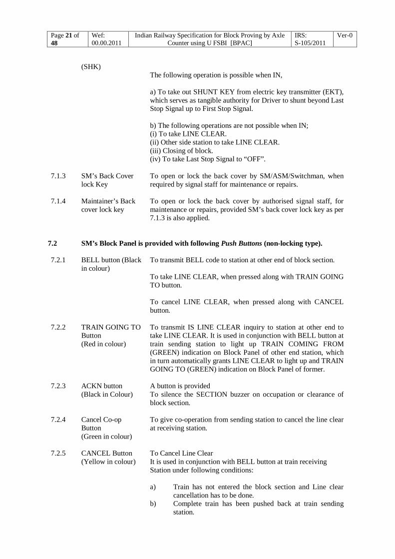
(SHK) The following operation is possible when IN, a) To take out SHUNT KEY from electric key transmitter (EKT), which serves as tangible authority for Driver to shunt beyond Last Stop Signal up to First Stop Signal. b) The following operations are not possible when IN; (i) To take LINE CLEAR. (ii) Other side station to take LINE CLEAR. (iii) Closing of block. (iv) To take Last Stop Signal to “OFF”.
7.1.3 SM’s Back Cover lock Key
To open or lock the back cover by SM/ASM/Switchman, when required by signal staff for maintenance or repairs.
7.1.4 Maintainer’s Back cover lock key
To open or lock the back cover by authorised signal staff, for maintenance or repairs, provided SM’s back cover lock key as per 7.1.3 is also applied.
7.2 SM’s Block Panel is provided with following Push Buttons (non-locking type). 7.2.1 BELL button (Black
in colour) To transmit BELL code to station at other end of block section. To take LINE CLEAR, when pressed along with TRAIN GOING TO button. To cancel LINE CLEAR, when pressed along with CANCEL button.
7.2.2 TRAIN GOING TO Button (Red in colour)
To transmit IS LINE CLEAR inquiry to station at other end to take LINE CLEAR. It is used in conjunction with BELL button at train sending station to light up TRAIN COMING FROM (GREEN) indication on Block Panel of other end station, which in turn automatically grants LINE CLEAR to light up and TRAIN GOING TO (GREEN) indication on Block Panel of former.
7.2.3 ACKN button (Black in Colour)
A button is provided To silence the SECTION buzzer on occupation or clearance of block section.
7.2.4 Cancel Co-op Button (Green in colour)
To give co-operation from sending station to cancel the line clear at receiving station.
7.2.5 CANCEL Button (Yellow in colour)
To Cancel Line Clear It is used in conjunction with BELL button at train receiving Station under following conditions: a) Train has not entered the block section and Line clear
cancellation has to be done. b) Complete train has been pushed back at train sending
station.

Page 22 of 48
Wef: 00.00.2011
Indian Railway Specification for Block Proving by Axle Counter using U FSBI [BPAC]
IRS: S-105/2011
Ver-0
7.3 Cancellation Counter
To register the cancellation of Line Clear. 7.4 Shunt key of EKT 7.4.1 An auxiliary EKT is provided with SM’s Block Panel to serve as SHUNTING Authority. 7.4.2 The Key of this transmitter is normally `IN' and used as tangible authority given to Driver of a
train to perform shunting upto opposing First Stop Signal (FSS). 7.4.3 Released when SHUNT RELEASE KEY of Block Panel is turned to `IN'. 8.0 Description of Block Panel for Double line 8.1 SM’s Block Panel is provided with following KEYS for various functions. 8.1.1 SM key SM/ASM/Switchman’s control key.
The key, when out, prevents following operations: a) Transmission of BELL code b) Transmission of IS LINE CLEAR inquiry request c) Cancellation of LINE CLEAR
8.1.2 LCB key LINE CLEAR BLOCKING key. It serves the following when out: (a) To prevent station in rear to take LINE CLEAR. (b) To prevent closing of Block.
8.1.3 SM’s Back Cover lock Key
To open or lock the back cover by SM/ASM/Switchman, when required by signal staff for maintenance or repairs.
8.1.4 Maintainer Back cover lock key
To open or lock the back cover by authorised signal staff, for maintenance or repairs, provided SM’s back cover lock key as per cl.8.1.3 is also applied.
8.2 SM’s Block Panel is provided with following PUSH BUTTONS (non-locking type) 8.2.1 BELL button (Black
in colour) To transmit BELL codes to station at other end of Block section. To take LINE CLEAR, when pressed along with TRAIN GOING
TO button.
To cancel LINE CLEAR, when pressed along with CANCEL button.

Page 23 of 48
Wef: 00.00.2011
Indian Railway Specification for Block Proving by Axle Counter using U FSBI [BPAC]
IRS: S-105/2011
Ver-0
8.2.2 TRAIN GOING TO Button (Red in colour)
To transmit IS LINE CLEAR inquiry to station in advance for taking LINE CLEAR. It is used in conjunction with BELL button at train sending station to light up TRAIN COMING FROM (GREEN) indication on Block Panel of receiving station, which in turn automatically grants LINE CLEAR to light up and TRAIN GOING TO (GREEN) indication on Block Panel of sending station.
8.2.3 ACKN button(s) (Black in Colour)
Two such buttons are provided, one each for despatch line and receive line. To silence the SECTION buzzer on occupation or clearance of
block section.
8.2.4 Cancel Co-op Button (Green in colour)
To give co-operation from sending station to cancel the line clear at receiving station.
8.2.5 CANCEL Button (Yellow in colour)
It is used in conjunction with BELL button at train receiving. Station under following conditions: a) Train has not entered the block section and Line clear
cancellation has to be done. b) Complete train has been pushed back at train sending station.
8.3 Cancellation Counter To register cancellation of line clear. 9.0 Method of Signalling Trains from Block Station to Block Station for Single Line

Page 24 of 48
Wef: 00.00.2011
Indian Railway Specification for Block Proving by Axle Counter using U FSBI [BPAC]
IRS: S-105/2011
Ver-0
a) SM of the station intending to send a train from his station has to obtain verbal consent from station at other end before taking LINE CLEAR on its Block Panel.
b) Before a request for IS LINE CLEAR is sent to station at other end, SM shall ensure the
following on its Block Panel:
i) LINE CLOSED indication YELLOW & ii) LINE FREE indication GREEN & iii) SNK indication YELLOW & iv) SNOEK indication YELLOW & v) SHUNT KEY indication GREEN
c) The station at other end while granting his consent shall ensure the following on its
Block Panel;
i) LINE CLOSED indication YELLOW & ii) LINE FREE indication GREEN & iii) SNK indication YELLOW & iv) SNOEK indication YELLOW & v) SHUNT KEY indication GREEN
d) Thereafter SM of sending station presses BELL & TRAIN GOING TO buttons. e) The directional arrowhead, TRAIN GOING TO/ TRAIN COMING FROM lights up
green at sending/receiving station respectively. f) SM of sending station releases BELL & TRAIN GOING TO buttons on getting TRAIN
GOING TO green indication. g) The sending station SM, after obtaining LINE CLEAR on its Block Panel, can send a
train into Block Section by taking the LSS to `OFF'. On entry of train into section, TRAIN ON LINE lights up at both the stations near arrowhead indication. The TRAIN GOING TO / TRAIN COMING FROM Arrow Head Indications turns RED in respective stations. SECTION buzzer sounds at both the stations along with ACKN indicator near ACKN button. Pressing of ACKN will turn off the buzzer and ACKN indicator.
h) The train is received at receiving station on proper reception signals. On complete arrival
of train, TRAIN COMING FROM indicator changes to FLASHING GREEN & LINE FREE indicator turns to GREEN at both the stations. TRAIN GOING TO /TRAIN COMING FROM indicator continues FLASHING GREEN at sending / receiving station respectively if reception & departure signals and their controls are not at normal or SHUNT KEY of EKT is `OUT'. In case reception & departure signals and their controls are at normal & SHUNT KEY of EKT is `IN' at sending/ receiving station, TRAIN GOING TO/ TRAIN COMING FROM turns off and LINE CLOSED indicator lights up YELLOW.
9.1 Following is the sequence of operations of signalling a train between two stations:
The block section being clear and the ‘LINE CLOSED’ indication being displayed on Block Panel at both the stations. The action is taken by sending stations SM as under:
Sending Station Receiving Station 1. SM ensures
LINE CLOSED indication YELLOW, SNK indication YELLOW,
2.

Page 25 of 48
Wef: 00.00.2011
Indian Railway Specification for Block Proving by Axle Counter using U FSBI [BPAC]
IRS: S-105/2011
Ver-0
SNOEK indication YELLOW, LINE FREE indication GREEN
SM inserts SM key & turns to IN. a) SM sends ‘Call Attention’ signal
to receiving station by pressing BELL button.
SM inserts SM key & turns to IN (a) SM acknowledges the ‘Call Attention’ signal by pressing BELL button.
3. SM sends ‘Attend Telephone’ signal by pressing BELL button.
4. SM acknowledges by pressing BELL button and attends telephone.
5. SM attends telephone and advises station at other end about the intended movement of the train on telephone & asks for LINE CLEAR after prescribed BELL code.
6. a) Exchanges information regarding train movement and ensures
LINE CLOSED indication YELLOW, SNK indication YELLOW, SNOEK indication YELLOW, LINE FREE indication GREEN & SHUNT KEY indication GREEN & b) Grants verbal LINE CLEAR.
7. SM presses BELL & TRAIN GOING TO buttons until ‘TRAIN GOING TO’ arrowhead indication lights up GREEN. (If aforesaid indicator does not appear after 3 seconds (approx.) of pressing the buttons, SM releases the buttons and rechecks conditions at his station and asks station at other end to recheck the conditions for grant of LINE CLEAR.)
8. ‘LINE CLOSED’ indicator turns off and ‘TRAIN COMING FROM’ arrowhead indication lights up GREEN .
9. ‘LINE CLOSED’ indicator turns off. ‘TRAIN GOING TO’ arrowhead indication lights up GREEN. Releases BELL & TRAIN GOING TO buttons.
10 Takes LSS to `OFF'. Train enters the Block Section.
11
LSS replaces to ‘ON’.

Page 26 of 48
Wef: 00.00.2011
Indian Railway Specification for Block Proving by Axle Counter using U FSBI [BPAC]
IRS: S-105/2011
Ver-0
LINE FREE indicator turns to RED. SECTION buzzer starts ringing & ‘TRAIN GOING TO’ arrowhead indication turns RED. ACKN indicator lights up. Acknowledges the buzzer by pressing ACKN button. ACKN indicator turns off.
LINE FREE indicator turns to RED . SECTION buzzer starts ringing & ‘TRAIN COMING FROM’ arrowhead indication turns RED. ACKN indicator lights up. Acknowledges the buzzer by pressing ACKN button. ACKN indicator turns off.
Puts back the LSS controls to Normal.
Ensures SNK lights up YELLOW. SNOEK lights up YELLOW Takes reception signal `OFF' to receive the train. Train passes Home Signal. Home Signal replaces to `ON'. Train clears the Block Section.
13 SECTION buzzer starts ringing. ACKN indicator lights up . LINE FREE indicator turns to GREEN `TRAIN GOING TO' arrowhead indication turns to FLASHING GREEN. Acknowledges the buzzer by pressing ACKN button. ACKN indicator turns off.
12 SECTION buzzer starts ringing. ACKN indicator light up & LINE FREE indicator turns to GREEN. ‘TRAIN COMING FROM’ arrowhead indication turns to FLASHING GREEN. Acknowledges the buzzer by pressing ACKN button. ACKN indicator turns off.
15 SNOEK lights up yellow.
14 Replaces all controls pertaining to reception of train to Normal. SNK lights up YELLOW.
`TRAIN GOING TO' arrowhead indication turns off. `LINE CLOSED' indicator lights up.
`TRAIN COMING FROM’ arrowhead indication turns off. ‘LINE CLOSED’ Indicator lights up.
9.2 REFUSAL TO ‘LINE CLEAR INQUIRY’
When a block section is blocked by the presence of a train in the section or train parting or shunting or opening of level crossing in mid section or for any other reason, the SHUNT key of EKT shall be taken out and kept in safe custody. If the block station at other end refuses the IS LINE CLEAR enquiry signal, no train shall be allowed to leave until a fresh IS LINE CLEAR enquiry signal has been given to block station at other end and accepted. On removal of obstruction, the Shunt Key of EKT shall be inserted and turned to IN position and the Shunt Release Key should be taken OUT.SM shall immediately inform SM of other end about the fact, so as to enable him to send a fresh IS LINE CLEAR signal.

Page 27 of 48
Wef: 00.00.2011
Indian Railway Specification for Block Proving by Axle Counter using U FSBI [BPAC]
IRS: S-105/2011
Ver-0
9.3 CLOSING OF BLOCK AFTER A PUSH BACK OPERATION
After a train has been pushed back at the sending station, the sending station advises the receiving station. The receiving station can close the section by pressing BELL and CANCEL button after getting cooperation from the other end station.
9.4 Method of Push Back operation
SENDING STATION RECEIVING STATION 1. Train clears the Block Section. LINE
FREE indicator turns GREEN. SECTION buzzer starts ringing. ACKN indicator lights up.
2. Train clears the Block Section. LINE FREE indicator turns GREEN. SECTION buzzer starts ringing. ACKN indicator lights up.
‘TRAIN GOING TO’ arrowhead indication turns to FLASHING GREEN.
‘TRAIN COMING FROM’ arrowhead indication turns to FLASHING GREEN.
Acknowledges the buzzer by pressing ACKN button. ACKN indicator turns off.
Acknowledges the buzzer by pressing ACKN button. ACKN indicator turns off.
3. Advises receiving end station SM about cancellation on telephone after prescribed BELL code.
4. Agrees to request, ensures SNK indicator YELLOW, SNOEK indicator YELLOW, SHUNT KEY indicator GREEN and Gives consent on telephone after prescribed BELL code
5. After verbal consent from other end SM Ensure SNK indication YELLOW, SNOEK indication YELLOW, SHUNT KEY indication GREEN
6.
Presses CANCEL CO-OP button and releases on receipt of BELL code.
CO-OP to light up YELLOW. Presses BELL & CANCEL button with SM key IN. CANCEL COUNTER increments. CANCEL indication lights up FLASHING YELLOW & continues flashing for 120 seconds.
8. 7. On expiry of 120 seconds,
TRAIN GOING TO arrowhead indication turns off. LINE CLOSED indication lights up.
TRAIN COMING FROM arrowhead indication and CANCEL indication turns off. ‘LINE CLOSED’ indication lights up.
9.5 BLOCK BACK
The SM, who intends to Block Back the line, shall inform the SM of station at other end on telephone for permission to Block Back, who will acknowledge the message and grant permission supported by a private number. SM takes SHUNT key of EKT OUT and keeps in safe custody.

Page 28 of 48
Wef: 00.00.2011
Indian Railway Specification for Block Proving by Axle Counter using U FSBI [BPAC]
IRS: S-105/2011
Ver-0
The SM will then issue necessary authority to driver of train to perform shunting in Block Section. On completion of shunting, section clear message will be sent to SM of station at other end on telephone about obstruction removed supported by a private number, who in turn will acknowledge the same supported by a private number. Thereafter SM will insert SHUNT key of EKT and turn to `IN' position and takes out the shunt release key. All the entries in Train Signal Register (TSR) for this operation should be make in RED ink. The reasons for Block Back shall be recorded in remarks column against each entry.
Station in rear Station intending BLOCK BACK
2. Block Panel displays;
LINE CLOSED - YELLOW LINE FREE - GREEN SNOEK - YELLOW SHUNT KEY - GREEN
1. Block Panel displays; LINE CLOSED - YELLOW LINE FREE - GREEN SNOEK - YELLOW SHUNT KEY – GREEN
4. Acknowledges call attention / attend telephone signal.
3. Inserts SM key & turns, Gives call attention / attend telephone signal.
6. Attends telephone. 5 Attends telephone.
8. Acknowledges & gives consent by private number.
7 Inform intention to perform shunting in Block Section.
10 SNOEK turns off. 9 Takes Shunt Key 'OUT' from EKT and keeps in safe custody. Issue necessary authority to driver of train to perform shunting in Block Section. SHUNT KEY indication turns to RED.
12. On entry of train in Block Section, SECTION buzzer starts ringing & ACKN indication lights up.
11. On entry of train in Block Section, SECTION buzzer starts ringing & ACKN indication lights up.
LINE FREE indication turns to RED. LINE CLOSED indication turns off.
LINE FREE indication turns to RED. LINE CLOSED indication turns off.
Acknowledges the buzzer by pressing ACKN button. ACKN indication turns off.
Acknowledges the buzzer by pressing ACKN button. ACKN indication turns off.
14. On clearing of Block Section. SECTION buzzer starts ringing & LINE CLOSED indication lights up. ACKN indication lights up.
13. On clearing of Block Section. SECTION buzzer starts ringing & LINE CLOSED indication lights up. ACKN indication lights up.
LINE FREE indication turns to GREEN. LINE CLOSED indication lights up YELLOW.
LINE FREE indicator turns to GREEN. LINE CLOSED indication lights up YELLOW.

Page 29 of 48
Wef: 00.00.2011
Indian Railway Specification for Block Proving by Axle Counter using U FSBI [BPAC]
IRS: S-105/2011
Ver-0
Acknowledges the buzzer by pressing ACKN button. ACKN indication turns off.
Acknowledges the buzzer by pressing ACKN button. ACKN indication turns off.
16. Acknowledges call attention /attend telephone signal.
15. On completion of shunting, SM verifies the line between opposite STARTER (if any)/ Shunt signal or Stop Board/ Fouling mark and FSS, free from any vehicle. Inserts SM key & turns, Gives call attention / attend telephone signal.
18. Attends telephone. 17. Attends telephone.
20. Acknowledges supported by a private number.
19. Inform shunting is completed supported by a private number.
22. SNOEK lights up YELLOW. 21. Inserts SHUNT KEY of EKT & turns to `IN'. SHUNT KEY indication turns to GREEN.
9.6 SHUNTING OF TRAIN Where shunt signals are not provided for shunting on line leading towards Block section, the driver of shunting train shall be given shunting order at the foot of STARTER SIGNAL /STOP BOARD/FOULING MARK before allowing any shunting. While shunting, the LAST STOP SIGNAL should be kept at ON. 9.6.1 SHUNTING UPTO LAST STOP SIGNAL SHUNT KEY of EKT shall be taken OUT and kept in safe custody. The driver of shunting train shall be given shunting order to shunt up to LSS. On completion of shunting, the line between STARTER/ Shunt Signal/ Stop Board/ Fouling mark and LSS should be checked free from any vehicle. SHUNT KEY of EKT shall be inserted and turned to IN position. When an IS LINE CLEAR enquiry is received from Block Station at other end of block section, permission for shunting up to LSS shall be granted only after compliance of GR 8.09 & 8.10 and as permitted by Station Working Rules (SWR). 9.6.2 SHUNTING BEHIND A TRAIN Shunting behind a train should be performed with message to station at other end. SM shall take out SHUNT KEY of EKT after entry of train beyond LSS and hand over to Driver of shunting train along with shunting order. On completion of shunting, Driver of shunting train hands over SHUNT KEY of EKT to SM. SM ensures clearance of line between STARTER/ Shunt Signal/ Stop Board / Fouling mark and LSS from any vehicle. The message regarding completion of shunting shall be sent to station at other end. SM inserts SHUNT KEY of EKT and turns to IN position. In case train arrives at station at other end before completion of shunting, TRAIN GOING TO/ TRAIN COMING FROM arrowhead indication will remain at RED, till shunting train clears the section. During such period line shall be BLOCKED BACK as per procedure laid down in the specification at Cl. 9.5.

Page 30 of 48
Wef: 00.00.2011
Indian Railway Specification for Block Proving by Axle Counter using U FSBI [BPAC]
IRS: S-105/2011
Ver-0
9.6.3 Shunting in face of an approaching Train 9.6.3.1 Shunting in face of an approaching train, towards LSS, where permitted in SWR by special
instructions, can be performed. The driver of shunting train shall be given shunting order to shunt up to LSS. On completion of shunting, the line between STARTER/ SHUNT SIGNAL/ STOP BOARD / FOULING MARK and FIRST STOP SIGNAL should be checked free from any vehicle.
9.6.3.2 Shunting in face of an approaching train, beyond LSS and up to FSS can be performed only,
when approaching train has been brought to a stop at FSS of the station. Whenever such shunting is to be performed, SM key shall be taken OUT and kept in safe custody. The driver of shunting train shall be given shunting order to shunt up to FSS. On completion of shunting, the line between STARTER/ SHUNT SIGNAL/ STOP BOARD / FOULING MARK AND FSS SIGNAL should be checked free from any vehicle and only then SM key shall be inserted and turned to IN position.
9.6.4 Shunting of Train beyond LSS in cases other than shunting behind a train or shunting in
face of approaching train
The shunting should be done under protection of Block Back only. 9.7 BLOCK FAILURES AND ACTION TO BE TAKEN:
The block failures can be categorised into the following: 9.7.1 Failure of BLOCK PANEL: Block panel should be considered to be defective and should not be restored for normal working until tested by competent signal staff & certified fit by them for use after the under-mentioned cases except for the case of Communication Link Failure (steady yellow indication). After the Communication Link Failure indication becomes flickering again block panel operation can be restored.
TYPE OF FAILURE ACTION TO BE TAKEN
1. When no indication of any sort, at all appears on the block panel or;
For case 1-11, Block Panel should be treated as defective block working suspended & trains should be dealt with by taking LINE CLEAR on the electrical communication equipment provided and by provisions of GR 14.13 & SR thereunder, if any.
2. When the Bell Code signals are received indistinctly or;
3. Any damage is seen or reported to block panel or;
4. When no train has entered into the block section but the ‘LINE FREE/OCCUPIED’ indicator changes to RED and this indication persists even after Resetting of Axle counter has been tried or:

Page 31 of 48
Wef: 00.00.2011
Indian Railway Specification for Block Proving by Axle Counter using U FSBI [BPAC]
IRS: S-105/2011
Ver-0
5. When ‘TRAIN GOING TO’ or ‘TRAIN COMING FROM’ arrowhead indications does not appear by appropriate action though condition for asking ‘LINE CLEAR’ and granting permission to approach are available and LINE CLOSED `YELLOW' is maintained or;
6. When a train arrives at the receiving station or pushes back at sending station, but Block Panel still shows ‘TRAIN COMING FROM & TRAIN GOING TO’ RED arrowhead indication or;
7. TRAIN GOING TO or TRAIN COMING FROM arrowhead indication does not turn to RED to give TRAIN ON LINE on the entry of train into Block Section at either of the stations or;
8. When a train has arrived at the receiving station but the Block Panel shows FLASHING GREEN indication even after ensuring SNK , SNOEK & SHUNT key indicator GREEN or;
9. When, after a Line Clear cancellation, CANCEL indicator does not light up FLASHING YELLOW or lights up steady YELLOW after appropriate actions or;
10. When UFSBI/Mux Fail indication appears. 11. When Communication Link Fail indication
becomes steady yellow. 12. When LSS can not be kept at ‘ON’ during its
suspension /disconnection. or;
In addition to action taken for case 1-11, all efforts should be made to keep the LSS at ON position. If it is not possible, then a competent railway servant should be deputed with RED hand signal at the foot of the LSS to warn the drivers of approaching trains.
13. When LSS of the station does not go back to ‘ON’ position on the entry of a train into the Block Section
In addition, all trains in the relevant direction should be stopped at Home signal and after ensuring that they have come to a stop, the Home signal should be cleared to caution aspect only.
To dispatch a train, STARTER signal should not be taken OFF until issue of relevant authority to pass LSS & Caution order should also be issued to the driver about the defect of LSS.
14. Total failure of communication during which train shall be worked as per extent rules in force on the Railway
In addition to action taken for case 1-13, the trains should be dealt with under the extent rules as laid down in GR 14.13 & SR there under

Page 32 of 48
Wef: 00.00.2011
Indian Railway Specification for Block Proving by Axle Counter using U FSBI [BPAC]
IRS: S-105/2011
Ver-0
9.7.2 Failure of LSS & Action to be taken
Cause of failure of the LSS
Action to be taken
1. When it cannot be taken OFF even though LINE CLEAR has been obtained; or;
The LSS should be considered to have failed & failure shall be informed to Signal staff immediately. The LINE CLEAR shall be obtained on the BLOCK PANEL & Line Clear ticket/Paper line clear as prevalent on railway shall be issued to driver of train
2. When it can be cleared without obtaining LINE CLEAR; or;
The LSS should be considered to have failed & failure shall be informed to Signal staff immediately and follow Cl. 9.7.1. 13 - 9.7.1.14
3. It does not restore to ON position on entry of train into Block Section
9.7.3 Suspension of Block Working & Action to be taken Cause of Suspension Action to be taken
1. When material lorry, Rail-cum-Road
vehicle, Motor trolley, Tie-tamping machines, Rail Motor/Bus or Tower wagon (4wheeler) has to run in the section.
BLOCK PANEL shall be suspended. These vehicles shall be worked on PAPER LINE CLEAR.
2. An accident takes place in the mid section.
BLOCK PANEL shall be suspended, if any line adjacent to line controlled by it is reported to be infringing, till the infringement exists. LSS shall be treated as INOPERATIVE & FAILED.
3. When any part of Block Panel is opened or removed for repairs under duly accepted disconnection notice.
BLOCK PANEL shall be suspended. LSS shall be treated as INOPERATIVE & FAILED.
4. When LSS of the station has been taken by Signal staff for repairs.
LSS shall be treated as INOPERATIVE & FAILED.
5. During Block FORWARD. LSS shall be treated as INOPERATIVE & FAILED.
When the cause of suspension of BLOCK PANEL and/or LSS is removed, SM shall restore the normal working of BLOCK PANEL / LSS, as the case may be. 9.8 Technical details of Block equipment 9.8.1 DESCRIPTION OF CIRCUIT WITH UFSBI:
Page 33 of 48
Wef: 00.00.2011
Indian Railway Specification for Block Proving by Axle Counter using U FSBI [BPAC]
IRS: S-105/2011
Ver-0
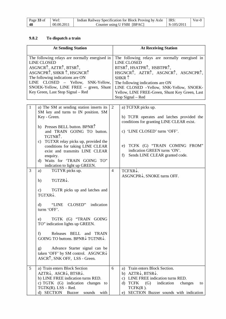
9.8.2 To dispatch a train
At Sending Station At Receiving Station
The following relays are normally energised in LINE CLOSED ASGNCR, AZTR, BTSR, ASGNCPR, SHKR , HSGNCR The following indications are ON LINE CLOSED – Yellow, SNK-Yellow, SNOEK-Yellow, LINE FREE – green, Shunt Key Green, Last Stop Signal – Red
The following relays are normally energised in LINE CLOSED BTSR, HSATPR, HSBTPR, HSGNCR, AZTR, ASGNCR, ASGNCPR, SHKR The following indications are ON LINE CLOSED –Yellow, SNK-Yellow, SNOEK-Yellow, LINE FREE-Green, Shunt Key Green, Last Stop Signal – Red
1 a) The SM at sending station inserts its
SM key and turns to IN position. SM Key - Green. b) Presses BELL button. BPNR and TRAIN GOING TO button.
TGTNR. c) TGTXR relay picks up, provided the
conditions for taking LINE CLEAR exist and transmits LINE CLEAR enquiry.
d) Waits for ‘TRAIN GOING TO” indication to light up GREEN.
2 a) TCFXR picks up.
b) TCFR operates and latches provided the conditions for granting LINE CLEAR exist. c) ‘LINE CLOSED’ turns ‘OFF’. e) TCFK (G) “TRAIN COMING FROM”
indication GREEN turns ‘ON’. f) Sends LINE CLEAR granted code.
3 a) TGTYR picks up. b) TGTZR. c) TGTR picks up and latches and TGTXR. d) “LINE CLOSED” indication turns ‘OFF’. e) TGTK (G) “TRAIN GOING TO” indication lights up GREEN. f) Releases BELL and TRAIN GOING TO buttons. BPNR TGTNR. g) Advance Starter signal can be taken ‘OFF’ by SM control. ASGNCR ASCR, SNK OFF, LSS - Green.
4 TCFXR. ASGNCPR, SNOKE turns OFF.
5 a) Train enters Block Section AZTR, ASCR, BTSR. b) LINE FREE indication turns RED. c) TGTK (G) indication changes to TGTK(R). LSS – Red. d) SECTION Buzzer sounds with
6 a) Train enters Block Section. b) AZTR, BTSR. c) LINE FREE indication turns RED. d) TCFK (G) indication changes to
TCFK(R ). e) SECTION Buzzer sounds with indication

Page 34 of 48
Wef: 00.00.2011
Indian Railway Specification for Block Proving by Axle Counter using U FSBI [BPAC]
IRS: S-105/2011
Ver-0
indication near ACKN button. e) SM presses ACKN to silence the SECTION buzzer and turn ‘OFF’ aforesaid indication. f) TGTYR. g) Restores all Signal controls to Normal. ASGNCR, SNK-Yellow h) Train in section.
near ACKN button. f) SM presses ACKN to silence the SECTION buzzer and turn ‘OFF’ aforesaid indication. ASGNCPR, SNOKE- YELLOW. Train in section.
7 a) Train is received by reversing the Home Signal Lever, (R) HSGNCR, SNK- ‘OFF’. b) Train occupies HSAT, (R) HSATPR, TAR1 and sticks. c) Train occupies HSBT, HSBTPR and clears HSAT, HSATPR TAR2 and sticks. d) TAR1. e) AZTR, Line Free-Green. f) SECTION Buzzer sounds with indication near ACKN button. g) SM presses ACKN to silence the SECTION buzzer and turn ‘OFF’ aforesaid indication. h) FR1 and FR2 operate to give flashing indications. i) TCFK(R) changes to TCFK (flashing green).
8. a) AZTR. b) LINE FREE indication turns GREEN. c) FR1 and FR2 operate to give flashing indications. d) TGTK(R) changes to TGTK (flashing green).
9. a) Normalises all controls to pick up HSGNCR. b) Waits for TGTZR to pick up and on its pick up, de-latches (R)TCFR. c) BTSR. d) LINE CLOSED indication turns ON. e) TCFK (flashing green) turns OFF.
10 a) TGTR, TGTZR. b) LINE CLOSED indication turns ON. c) TRAIN GOING TO (Flashing Green) indication turns OFF.
Note: For use with MUX-Combiner please refer Block Working Manual & Drawing Number RDSO/S-
32016.(Delete) 10.0 Method of Signaling Trains from Block Station to Block Station for Double Line. a) SM of the station intending to send a train from his station has to obtain verbal consent from station in
advance before taking LINE CLEAR on its Block Panel. b) Before a request for IS LINE CLEAR is sent to station in advance, SM of sending station shall ensure
the following near TRAIN GOING TO arrowhead on its Block Panel:

Page 35 of 48
Wef: 00.00.2011
Indian Railway Specification for Block Proving by Axle Counter using U FSBI [BPAC]
IRS: S-105/2011
Ver-0
i) LINE CLOSED indication YELLOW & ii) LINE FREE indication GREEN & iii) SNK indication YELLOW.
c) The station in advance while granting his verbal consent shall ensure the following near TRAIN
COMING FROM arrowhead on its Block Panel:
i) LINE CLOSED indication YELLOW & ii) LINE FREE indication GREEN &
iii) SNK indication YELLOW &
iv) SNOEK indication YELLOW
Then inserts and turns LCB key.
d) Thereafter SM of sending station presses BELL & TRAIN GOING TO buttons. e) The arrowhead, TRAIN GOING TO/ TRAIN COMING FROM lights up green at sending/receiving
station respectively. f) SM of sending station releases BELL & TRAIN GOING TO buttons on getting TRAIN GOING TO
green indication. g) The sending station SM after obtaining LINE CLEAR on its Block Panel can send the train into Block
Section by taking the LSS to `OFF'. On entry of train into section, TRAIN ON LINE lights up RED at both the stations in arrowhead indication. SECTION buzzer sounds at both the stations along with ACKN indication near respective ACKN button. Pressing of ACKN button of concerned line (Despatch/Receive) will turn off the buzzer and ACKN indication.
h) The train is received at receiving station on proper reception signals. On complete arrival of train,
TRAIN GOING TO /TRAIN COMING FROM arrowhead indication turns to FLASHING GREEN & LINE FREE indication turns to GREEN at both the stations. TRAIN GOING TO /TRAIN COMING FROM arrowhead indication continues FLASHING GREEN at sending / receiving station respectively till reception & departure signals and their controls are not at normal or LCB Key is not `IN'. In case reception & departure signals and their controls are at normal & LCB key is IN, TRAIN GOING TO /TRAIN COMING FROM arrowhead indication turns off and LINE CLOSED indication lights up YELLOW.
10.1 Following is the sequence of operations of signalling a train between two stations:
The block section being clear and the ‘LINE CLOSED’ indication being displayed on Block Panel at both the stations. The action is taken by sending stations SM as under:
Sending Station
Receiving Station
1. SM ensures LINE CLOSED indication YELLOW, SNK indication YELLOW, LINE FREE indication GREEN. a) SM inserts SM key & turns to IN. b) SM sends ‘Call Attention’ signal to
2.

Page 36 of 48
Wef: 00.00.2011
Indian Railway Specification for Block Proving by Axle Counter using U FSBI [BPAC]
IRS: S-105/2011
Ver-0
receiving station by pressing BELL button. SM acknowledges the ‘Call Attention’ signal by pressing BELL button.
3. SM sends ‘Attend Telephone’ signal by pressing BELL button.
4. SM acknowledges by pressing BELL button and attends telephone.
5. SM attends telephone and advises station in advance about the intended movement of the train on telephone & asks for LINE CLEAR.
6. a) Exchanges information regarding train movement and ensures LINE CLOSED indication YELLOW, SNK indication YELLOW, LINE FREE indicator GREEN & LCB key IN &
b) Grants verbal LINE CLEAR. 7. SM presses BELL & TRAIN GOING TO
buttons until ‘TRAIN GOING TO’ arrowhead indication lights up GREEN. (If aforesaid indication does not appear after 3 seconds (approx.) of pressing the buttons, SM releases the buttons and rechecks conditions at his station and asks station in advance to recheck the conditions for grant of LINE CLEAR.)
8. ‘LINE CLOSED’ indication turns off and ‘TRAIN COMING FROM’ arrowhead indication lights up GREEN.
9. ‘LINE CLOSED’ indication turns off. ‘TRAIN GOING TO’ arrowhead indication lights up GREEN. Releases BELL & TRAIN GOING TO buttons.
10 Takes LSS to `OFF' Train enters the Block Section. LSS replaces to ‘ON’. LINE OCCUPIED indication lights up RED. SECTION buzzer starts ringing & ‘TRAIN GOING TO’ Arrow Head Indication turns RED. ACKN indication lights up. Acknowledges the buzzer by pressing ACKN button. ACKN indication turns off. Puts back the LSS controls to Normal. Ensures SNK lights up YELLOW .
11 LINE OCCUPIED indication lights up RED. SECTION buzzer starts ringing & ‘TRAIN COMING FROM’ Arrow Head Indication turns RED. ACKN indication lights up. Acknowledges the buzzer by pressing ACKN button. ACKN indication turns off. SNOEK lights up YELLOW. Takes reception signal(s) `OFF' to receive the train. Train passes Home Signal. Signal replaces to `ON'. Train clears the Block Section including Block overlap.

Page 37 of 48
Wef: 00.00.2011
Indian Railway Specification for Block Proving by Axle Counter using U FSBI [BPAC]
IRS: S-105/2011
Ver-0
13 SECTION buzzer starts ringing. ACKN indication lights up YELLOW. LINE FREE indication turns to GREEN. `TRAIN GOING TO' indication turns FLASHING GREEN. Acknowledges the buzzer by pressing ACKN button. ACKN indication turns off.
12 SECTION buzzer starts ringing. ACKN indication lights up YELLOW. LINE FREE indication turns to GREEN. ‘TRAIN COMING FROM’ Arrow Head Indication turns FLASHING GREEN. Acknowledges the buzzer by pressing ACKN button. ACKN indication turns off.
15
14 Replaces all controls pertaining to reception of train to Normal. SNK lights up YELLOW.
`TRAIN GOING TO' Arrow Head Indication turns off. `LINE CLOSED' indication lights up.
`TRAIN COMING FROM’ Arrow Head Indication turns off. ‘LINE CLOSED’ indication lights up.
10.2 REFUSAL TO ‘LINE CLEAR ENQUIRY’ When the line is being blocked by the presence of a train in the section or train parting or shunting or opening of level crossing in mid section or for any other reason, the LCB key shall be taken out and kept in safe custody. On removal of obstruction, SM shall immediately inform SM of station in rear about the fact and put LCB Key IN, so as to enable him to send a fresh LINE CLEAR ENQUIRY. 10.3 CLOSING OF BLOCK AFTER A PUSH BACK OPERATION After a train has been pushed back at the sending station, the sending station advises the receiving station. The receiving station can close the section by pressing BELL & CANCEL button after getting cooperation from sending station. 10.4 Method of Push Back operation
SENDING STATION
RECEIVING STATION
1. Train clears the Block Section. LINE FREE indication turns GREEN. SECTION buzzer starts ringing. ACKN indication lights up. ‘TRAIN GOING TO’ arrowhead indication turns to FLASHING GREEN. Acknowledges the buzzer by pressing ACKN button. ACKN indication turns off. Ensure SNK indication YELLOW.
2 Train clears the Block Section. LINE FREE indication turns GREEN. SECTION buzzer starts ringing. ACKN indication lights up. ‘TRAIN COMING FROM’ arrowhead indication turns to FLASHING GREEN. Acknowledges the buzzer by pressing ACKN button. ACKN indication turns off.
3. Advises other end station SM to close the block, on telephone after prescribed BELL code.
4. On request from sending station SM about closing of block on telephone after prescribed BELL code. Ensures SNK indication YELLOW.
5.
Gives co-operation to other end station for cancellation.
6. Co-operation indication light up yellow. BELL and CANCEL button pressed,

Page 38 of 48
Wef: 00.00.2011
Indian Railway Specification for Block Proving by Axle Counter using U FSBI [BPAC]
IRS: S-105/2011
Ver-0
Released with SM key IN, Cancel counter increments CANCEL indication lights up FLASHING YELLOW and continues flashing for 120 seconds.
8. TRAIN GOING TO Arrow Head Indication turns off. LINE CLOSED indication lights up.
7. On expiry of 120 seconds, TRAIN COMING FROM arrowhead indication & cancel indications turn off. LINE CLOSED indication lights up.
10.5 BLOCK BACK The SM, who intends to Block Back the line, shall inform the SM of station in rear on telephone for permission to Block Back, who will acknowledge the message and grant permission supported by a private number. SM who intends to block back takes LCB key OUT and keeps in safe custody. The SM will then issue necessary authority to driver of train to perform shunting in Block Section. On completion of shunting, section clear message will be sent to SM of station in rear on telephone about obstruction removed supported by a private number, who in turn will acknowledge the same supported by a private number. Thereafter SM will insert LCB Key and turn to IN position. All the entries in Train Signal Register (TSR) for this operation should be make in RED ink. The reasons for Block Back shall be recorded in remarks column against each entry.
Station in rear Station intending BLOCK BACK 2. Block Panel displays;
LINE CLOSED – YELLOW LINE FREE – GREEN SNK - YELLOW
1. Block Panel displays; LINE CLOSED – YELLOW LINE FREE – GREEN SNOEK - YELLOW
4. Acknowledges call attention / attend telephone signal.
3. Inserts SM key and turns, Gives call attention / attend telephone signal.
6. Attends telephone. 5. Attends telephone. 8. Acknowledges and gives consent by
private number. 7. Inform intention to block back for shunting in
Block Section. 9. The LCB is taken out and kept in safe custody.
Issue necessary authority to driver of train to perform shunting in Block Section.
11. On entry of train in Block Section, SECTION buzzer starts ringing and LINE CLOSED indication turns off. ACKN indication lights up. LINE OCCUPIED indication lights up RED. Acknowledges the buzzer by pressing ACKN button. ACKN indication turns off.
10.
On entry of train in Block Section, SECTION buzzer starts ringing and LINE CLOSED indication turns off. ACKN indication lights up. LINE OCCUPIED indication lights up RED. Acknowledges the buzzer by pressing ACKN button. ACKN indication turns off.
13. On clearing of Block Section. SECTION buzzer starts ringing and LINE CLOSED indication lights up. ACKN indication lights up. LINE FREE indication turns to GREEN. Acknowledges the buzzer by pressing ACKN button. ACKN indication turns off.
12.
On clearing of Block Section. SECTION buzzer starts ringing and LINE CLOSED indication lights up. ACKN indication lights up. LINE FREE indication turns to GREEN. Acknowledges the buzzer by pressing ACKN button. ACKN indication turns off.

Page 39 of 48
Wef: 00.00.2011
Indian Railway Specification for Block Proving by Axle Counter using U FSBI [BPAC]
IRS: S-105/2011
Ver-0
15. Acknowledges call attention /attend telephone signal.
14 On completion of shunting, SM verifies the line between opposite STARTER (if any) / Shunt signal or Block section Limit Board/ Stop Board/fouling mark and FIRST STOP SIGNAL, free from any vehicle.
17. Attends telephone. 16 Attends telephone. 19. Acknowledges supported by a private
number. 18 Informs shunting is completed supported by a
private number. 20 Inserts LCB and turns in. 10.6 BLOCK FORWARD
The SM, who intends to Block forward the line, shall inform the SM of station in advance on Telephone for permission to Block forward, who will acknowledge the message and grant permission supported by a private number. The SM of advance station takes LCB key OUT and keeps in safe custody. The SM of this station will then issue necessary authority to driver of train to perform shunting in Block Section.
On completion of shunting, message will be sent to SM of station in advance on telephone about obstruction removed supported by a private number, who in turn will acknowledge the same supported by a private number. Thereafter SM of advance station will insert LCB key and turn to IN position.
All the entries in Train Signal Register for this operation should be made in RED ink. The reasons for Block forward shall be recorded in remarks column against each entry.
Station intending BLOCK FORWARD Station in advance 1. Block Panel displays;
LINE CLOSED – YELLOW LINE FREE – GREEN
2. Block Panel displays; LINE CLOSED – YELLOW LINE FREE – GREEN
3. Inserts SM key and turns, Gives call attention /attend telephone signal.
4. Acknowledges call attention / attend telephone signal.
5. Attends telephone.
6. Attends telephone.
7. Inform intention to perform shunting in Block Section.
8. Acknowledges and gives consent by private number.
10. Issue necessary authority to driver of train to perform shunting in Block Section.
9. The LCB Key is taken out and kept in safe custody.
11. On entry of train in Block section, SECTION buzzer starts ringing and LINE CLOSED indication turns off. ACKN indication lights up. LINE FREE indication turns to RED. Acknowledges the buzzer by pressing ACKN button. ACKN indication turns off.
12. On entry of train in Block section, SECTION buzzer starts ringing and LINE CLOSED indication turns off. ACKN indication lights up Yellow. LINE FREE indication turns to RED. Acknowledges the buzzer by pressing ACKN button. ACKN indication turns off.
13. On clearing of Block Section. 14 On clearing of Block Section

Page 40 of 48
Wef: 00.00.2011
Indian Railway Specification for Block Proving by Axle Counter using U FSBI [BPAC]
IRS: S-105/2011
Ver-0
SECTION buzzer starts ringing and LINE CLOSED indication lights up yellow. ACKN indication lights up Yellow. LINE FREE indication turns to GREEN. Acknowledges the buzzer by pressing ACKN button. ACKN indication turns off.
SECTION buzzer starts ringing and LINE CLOSED indication lights up. ACKN indication lights up yellow. LINE FREE indication turns to GREEN. Acknowledges the buzzer by pressing ACKN button. ACKN indication turns off.
15. On completion of shunting, SM verifies the line between STARTER /Shunt signal/Stop Board/fouling mark and LAST STOP SIGNAL, free from any vehicle. Inserts SM key and turn. Gives call attention to attend telephone.
16. Acknowledges call attention to attend telephone.
18. Attends telephone.
17. Attends telephone.
20. Inform shunting is completed supported by a private number.
19. Acknowledges supported by a private number.
21. Inserts LCB and turn in.
10.7 SHUNTING OF TRAIN
Where shunt signals are not provided for shunting on line leading towards Block section, the driver of shunting train shall be given shunting order at the foot of STARTER SIGNAL /STOP BOARD/FOULING MARK before allowing any shunting.
10.7.1 HUNTING OF TRAIN UP TO LAST STOP SIGNAL
While shunting on dispatch line, the LAST STOP SIGNAL should be kept at ON. SM Key shall be taken out. The driver of shunting train shall be given shunting order to shunt up to LAST STOP SIGNAL. On completion of shunting, the line between STARTER/Shunt Signal/Stop Board/fouling mark and LAST STOP SIGNAL should be checked free from any vehicle and only then SM key shall be inserted and turned to IN position.
10.7.2 SHUNTING BEHIND A TRAIN
Shunting behind a train should be performed with a message to station in advance. The station in advance shall take LCB Key out and keep in safe custody. Shunting shall be performed as per 10.7.1. On completion of shunting, SM of sending station verifies the line between STARTER/Shunt Signal/Stop Board /Fouling Mark and LAST STOP SIGNAL free from any vehicle. The message regarding completion of shunting shall be sent to station in advance. SM of station in advance inserts LCB Key and turns to IN position.
10.7.3 SHUNTING OF TRAIN BEYOND LAST STOP SIGNAL
The shunting shall be done under protection of Block Forward only.
10.7.4 SHUNTING OF TRAIN TOWARDS FIRST STOP SIGNAL
The shunting shall be done under protection of Block Back only.

Page 41 of 48
Wef: 00.00.2011
Indian Railway Specification for Block Proving by Axle Counter using U FSBI [BPAC]
IRS: S-105/2011
Ver-0
10.7.5 SHUNTING OF TRAIN IN FACE OF APPROACHING TRAIN
No shunting in face of approaching train, towards receive line should be permitted, until the approaching train has been brought to a stop at first stop signal of the station. Whenever such shunting is to be performed, LCB Key shall be taken OUT and kept in safe custody. The driver of shunting train shall be given shunting order to shunt up to FIRST STOP SIGNAL. On completion of shunting, the line between STARTER/SHUNT SIGNAL/STOP BOARD / FOULING MARK AND FIRST STOP SIGNAL should be checked free from any vehicle and only then LCB key shall be inserted and turned to IN position.
10.8 BLOCK FAILURES AND ACTION TO BE TAKEN: The block failures can be categorised into the following: 10.8.1 FAILURE OF THE BLOCK PANEL:
Block panel should be considered defective for Up and /or Down trains, as the case may be. The Block Panel should not be restored for normal working until tested by competent signal staff and certified fit by them for use after the under-mentioned cases except for the case of Communication Link Failure (steady yellow indication). After the Communication Link Failure indication becomes flickering again block panel operation can be restored.
CAUSE OF FAILURE ACTION TO BE TAKEN
1. When no indication of any sort, at all appears on the block panel or; 2. When the Bell Code signals are received indistinctly or; 3. Any damage is seen or reported to block equipment or; 4. When none of the indications viz. ‘TRAIN COMING FROM and TRAIN GOING TO’ appears on the block panel except ‘LINE FREE’ or; 5. When no train has entered into the block section but the ‘LINE OCCUPIED’ indication lights on RED on both lines and these indication persists even after resetting of the Axle Counters have been tried. or: 6. When a train has arrived at the receiving station but the Block Panel still shows ‘TRAIN ON LINE’ RED indication and persist on both lines or; 7. When BI Fail indication comes. or; 8. When Link Fail indication becomes steady yellow. 9. When ‘TRAIN GOING TO’ or ‘TRAIN COMING FROM’ Arrow Head Indications do not appear by appropriate action though condition for asking ‘LINE CLEAR’ and granting permission to approach are available. or;
For case 1-9, Block Panel should be treated as defective block working suspended and trains should be dealt with by taking LINE CLEAR on the electrical communication equipment provided and by provisions of GR 14.13 and SR there under, if any.

Page 42 of 48
Wef: 00.00.2011
Indian Railway Specification for Block Proving by Axle Counter using U FSBI [BPAC]
IRS: S-105/2011
Ver-0
10. TRAIN GOING TO or TRAIN COMING FROM Arrow Head Indications does not turn to RED to give TRAIN ON LINE on the entry of train into Block Section at either of the stations or; 11. When a train has arrived at the receiving station but the Block Panel shows FLASHING GREEN/GREEN indication even after ensuring SNK indication and LCB key IN or; 12. When, after a cancellation, CANCEL indication does not light up FLASHING YELLOW or STEADY YELLOW after appropriate actions or; 13. When Last Stop Signal cannot be kept at ‘ON’ during its suspension /disconnection. 14. When Last Stop Signal of the station does not go back to ‘ON’ position on the entry of a train into the Block Section
For case 10-12, the Block Panel should be treated as defective for respective line, Block working suspended for respective line and trains should be dealt with by taking LINE CLEAR on the electrical communication equipment provided and by provisions of GR 14.13 and SR thereunder, if any. In addition to action taken for case 1-12, all efforts should be made to keep the LAST STOP SIGNAL at ON position. If it is not possible, then a competent railway servant should be deputed with RED hand signal at the foot of the LAST STOP SIGNAL to warn the drivers of the approaching trains. In addition all trains in the relevant direction should be stopped at Home signal and after ensuring that they have come to a stop, the Home signal should be cleared to caution aspect only. The STARTER signal should not be taken OFF until the issue of relevant authority to pass the STARTER and LAST STOP SIGNAL to the driver. Caution order should also be issued to the driver about the defect of LAST STOP SIGNAL.
15. Total failure of communication during which train shall be worked as per extent rules in force on the Railway
In addition to action taken for case 1-14, the trains should be dealt with under the extent rules as outlined in GR 14.13 and SR there under
10.8.2 FAILURE OF LAST STOP SIGNAL AND ACTION TO BE TAKEN
Cause of failure of the LAST STOP SIGNAL
Action to be taken
1. When it cannot be taken OFF even though LINE CLEAR has been obtained; or;
The LAST STOP SIGNAL should be considered to have failed and failure shall be informed to Signal staff immediately. The LINE CLEAR shall be obtained on the BLOCK PANEL and Line Clear ticket/Paper line clear as prevalent on railway shall be issued to driver of train.
2. When it can be cleared without obtaining LINE CLEAR; or;
The LAST STOP SIGNAL should be considered to have failed and failure shall be informed to Signal staff immediately and follow 10.8.1.16-10.8.1.17.
3. It do not restore to ON position on entry of train into Block Section.
The LAST STOP SIGNAL should be considered to have failed and failure shall be informed to Signal staff immediately and follow 10.8.1.16-10.8.1.17.

Page 43 of 48
Wef: 00.00.2011
Indian Railway Specification for Block Proving by Axle Counter using U FSBI [BPAC]
IRS: S-105/2011
Ver-0
10.8.3 SUSPENSION OF BLOCK WORKING AND ACTION TO BE TAKEN
Cause of Suspension Action to be taken
1. When material lorries or Motor trolleys or Tie-tamping machines or Rail Motor/ Bus or Rail cum road vehicle or Tower wagon (4 wheeler) has to run in the section.
BLOCK PANEL shall be suspended for respective line and these vehicles shall be worked on PAPER LINE CLEAR.
2. An accident takes place in the mid section.
BLOCK PANEL shall be suspended for both lines, if line adjacent to affected line is reported to be infringed, till the infringement exists for dispatch line or, LAST STOP SIGNAL shall be treated as INOPERATIVE and FAILED.
3. When any part of Block Panel is opened or removed for repairs under duly accepted disconnection notice.
BLOCK PANEL shall be suspended LAST STOP SIGNAL shall be treated as INOPERATIVE and FAILED.
4. When Last Stop Signal of the station has been taken by Signal staff for repairs.
LAST STOP SIGNAL shall be treated as INOPERATIVE and FAILED.
5. During Block FORWARD. LAST STOP SIGNAL shall be treated as INOPERATIVE and FAILED.
10.8.3.1 When the cause of suspension of BLOCK PANEL and/or LAST STOP SIGNAL is
removed the normal working of BLOCK PANEL and/or LSS as the case may be, shall be restored by SM.
10.9 TECHNICAL SCHEME: 10.9.1 DESCRIPTION OF CIRCUIT WITH UFSBI: 10.9.2 To dispatch a train At Sending Station At Receiving Station
The following relays are normally energised in LINE CLOSED. ASGNCR, [D] AZTR. The following indications are ON. LINE CLOSED – Yellow, SNK-Yellow, LINE FREE – green, Last Stop Signal – Red.
The following relays are normally energised in LINE CLOSED. BTSR, HSATPR, HSBTPR, ASGNCPR, [R] AZTR. HSGNCR. The LCB key is IN. The following indications are ON. LINE CLOSED –Yellow, SNK-Yellow, LINE FREE-Green, SNOEK-Yellow, Last Stop Signal – Red.
1 a) The SM at sending station
inserts its SM key and turns to IN position. SM Key – Green. b) Presses BELL button. BPNR and
TRAIN GOING TO button. TGTNR.
c) TGTXR relay picks up, provided the
2 a) TCFXR picks up. b) TCFR operates and latches, provided the conditions for granting LINE CLEAR exist. c) ‘LINE CLOSED’ turns ‘OFF’. d) TCFK (G) “TRAIN COMING FROM” indication GREEN turns ‘ON’. e) Sends LINE CLEAR granted code.
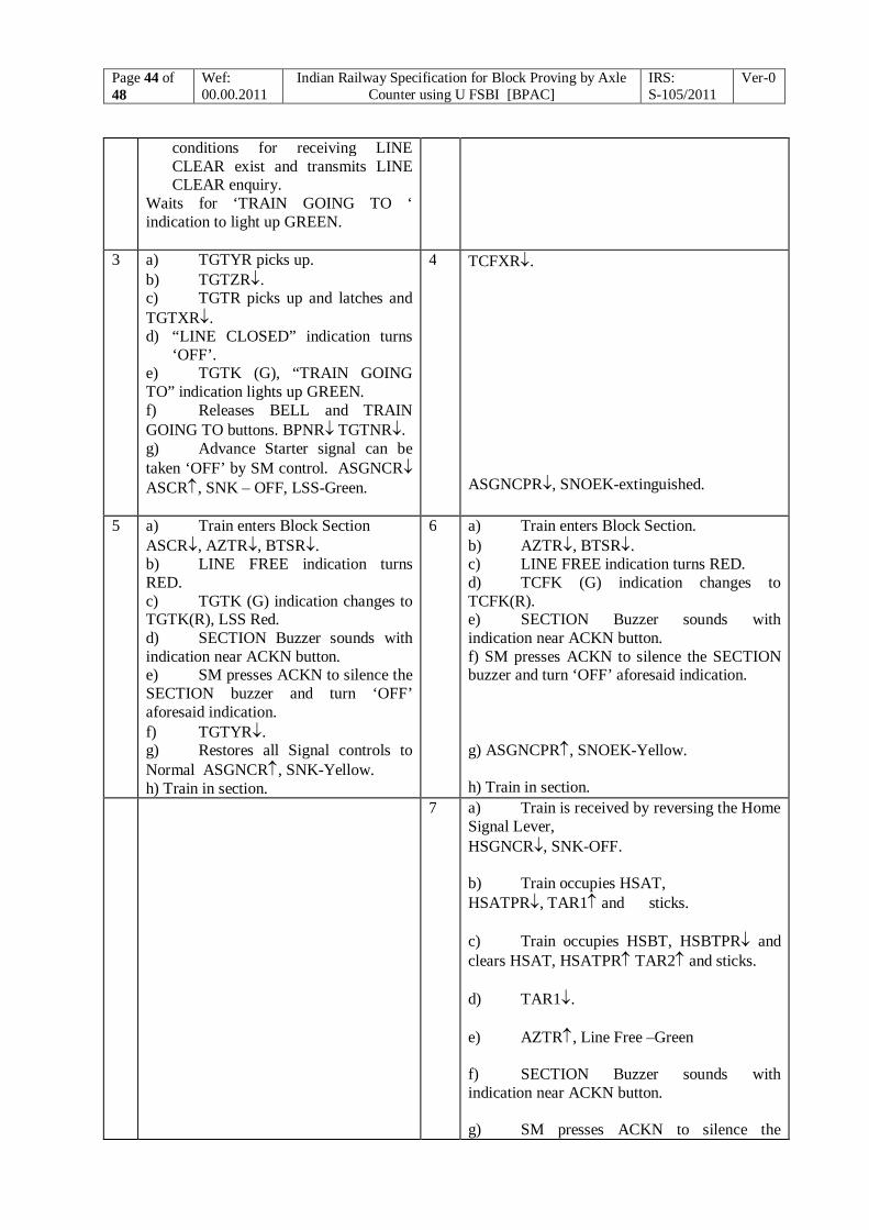
Page 44 of 48
Wef: 00.00.2011
Indian Railway Specification for Block Proving by Axle Counter using U FSBI [BPAC]
IRS: S-105/2011
Ver-0
conditions for receiving LINE CLEAR exist and transmits LINE CLEAR enquiry.
Waits for ‘TRAIN GOING TO ‘ indication to light up GREEN.
3 a) TGTYR picks up. b) TGTZR. c) TGTR picks up and latches and TGTXR. d) “LINE CLOSED” indication turns
‘OFF’. e) TGTK (G), “TRAIN GOING TO” indication lights up GREEN. f) Releases BELL and TRAIN GOING TO buttons. BPNR TGTNR. g) Advance Starter signal can be taken ‘OFF’ by SM control. ASGNCR ASCR, SNK – OFF, LSS-Green.
4 TCFXR. ASGNCPR, SNOEK-extinguished.
5 a) Train enters Block Section ASCR, AZTR, BTSR. b) LINE FREE indication turns RED. c) TGTK (G) indication changes to TGTK(R), LSS Red. d) SECTION Buzzer sounds with indication near ACKN button. e) SM presses ACKN to silence the SECTION buzzer and turn ‘OFF’ aforesaid indication. f) TGTYR. g) Restores all Signal controls to Normal ASGNCR, SNK-Yellow. h) Train in section.
6 a) Train enters Block Section. b) AZTR, BTSR. c) LINE FREE indication turns RED. d) TCFK (G) indication changes to TCFK(R). e) SECTION Buzzer sounds with indication near ACKN button. f) SM presses ACKN to silence the SECTION buzzer and turn ‘OFF’ aforesaid indication. g) ASGNCPR, SNOEK-Yellow. h) Train in section.
7 a) Train is received by reversing the Home Signal Lever, HSGNCR, SNK-OFF. b) Train occupies HSAT, HSATPR, TAR1 and sticks. c) Train occupies HSBT, HSBTPR and clears HSAT, HSATPR TAR2 and sticks. d) TAR1. e) AZTR, Line Free –Green f) SECTION Buzzer sounds with indication near ACKN button. g) SM presses ACKN to silence the
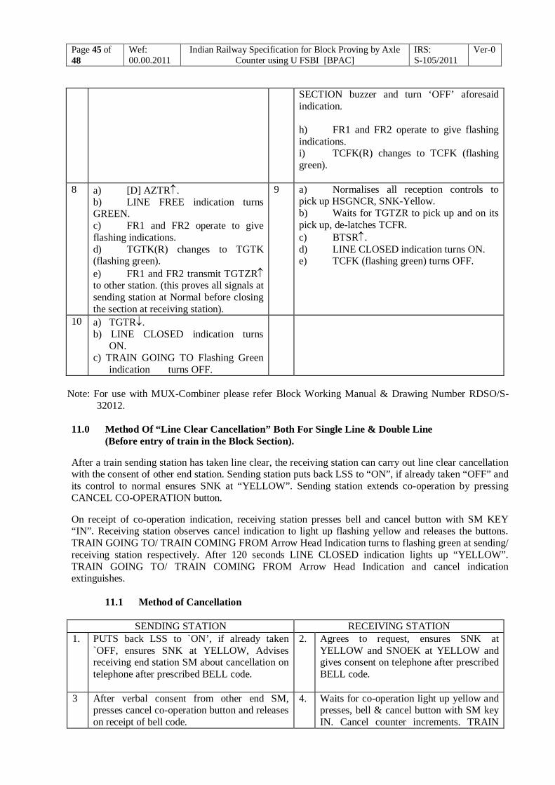
Page 45 of 48
Wef: 00.00.2011
Indian Railway Specification for Block Proving by Axle Counter using U FSBI [BPAC]
IRS: S-105/2011
Ver-0
SECTION buzzer and turn ‘OFF’ aforesaid indication. h) FR1 and FR2 operate to give flashing indications. i) TCFK(R) changes to TCFK (flashing green).
8 a) [D] AZTR. b) LINE FREE indication turns GREEN. c) FR1 and FR2 operate to give flashing indications. d) TGTK(R) changes to TGTK (flashing green). e) FR1 and FR2 transmit TGTZR to other station. (this proves all signals at sending station at Normal before closing the section at receiving station).
9 a) Normalises all reception controls to pick up HSGNCR, SNK-Yellow. b) Waits for TGTZR to pick up and on its pick up, de-latches TCFR. c) BTSR. d) LINE CLOSED indication turns ON. e) TCFK (flashing green) turns OFF.
10 a) TGTR. b) LINE CLOSED indication turns
ON. c) TRAIN GOING TO Flashing Green
indication turns OFF.
Note: For use with MUX-Combiner please refer Block Working Manual & Drawing Number RDSO/S-
32012. 11.0 Method Of “Line Clear Cancellation” Both For Single Line & Double Line
(Before entry of train in the Block Section). After a train sending station has taken line clear, the receiving station can carry out line clear cancellation with the consent of other end station. Sending station puts back LSS to “ON”, if already taken “OFF” and its control to normal ensures SNK at “YELLOW”. Sending station extends co-operation by pressing CANCEL CO-OPERATION button. On receipt of co-operation indication, receiving station presses bell and cancel button with SM KEY “IN”. Receiving station observes cancel indication to light up flashing yellow and releases the buttons. TRAIN GOING TO/ TRAIN COMING FROM Arrow Head Indication turns to flashing green at sending/ receiving station respectively. After 120 seconds LINE CLOSED indication lights up “YELLOW”. TRAIN GOING TO/ TRAIN COMING FROM Arrow Head Indication and cancel indication extinguishes.
11.1 Method of Cancellation
SENDING STATION RECEIVING STATION 1. PUTS back LSS to `ON’, if already taken
`OFF, ensures SNK at YELLOW, Advises receiving end station SM about cancellation on telephone after prescribed BELL code.
2. Agrees to request, ensures SNK at YELLOW and SNOEK at YELLOW and gives consent on telephone after prescribed BELL code.
3 After verbal consent from other end SM, presses cancel co-operation button and releases on receipt of bell code.
4. Waits for co-operation light up yellow and presses, bell & cancel button with SM key IN. Cancel counter increments. TRAIN
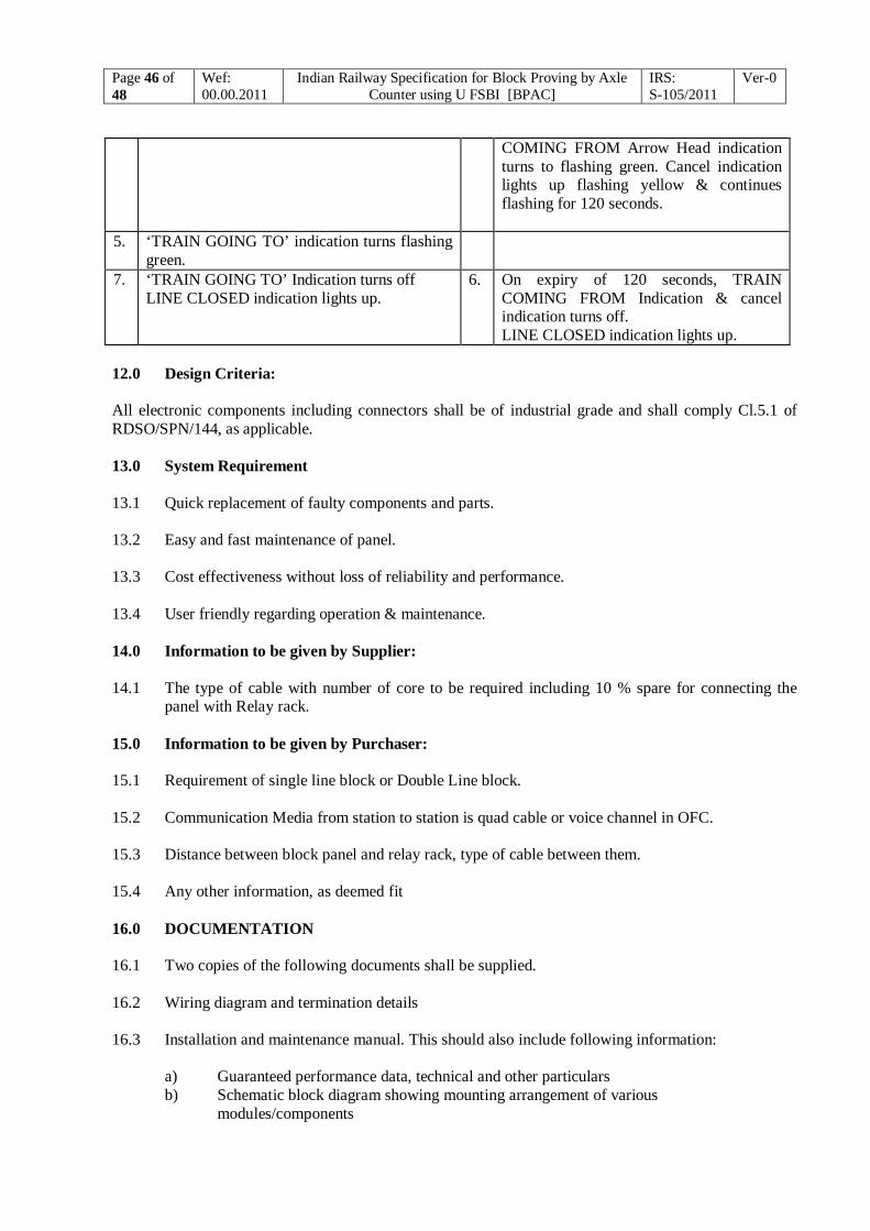
Page 46 of 48
Wef: 00.00.2011
Indian Railway Specification for Block Proving by Axle Counter using U FSBI [BPAC]
IRS: S-105/2011
Ver-0
COMING FROM Arrow Head indication turns to flashing green. Cancel indication lights up flashing yellow & continues flashing for 120 seconds.
5. ‘TRAIN GOING TO’ indication turns flashing green.
7. ‘TRAIN GOING TO’ Indication turns off LINE CLOSED indication lights up.
6. On expiry of 120 seconds, TRAIN COMING FROM Indication & cancel indication turns off. LINE CLOSED indication lights up.
12.0 Design Criteria: All electronic components including connectors shall be of industrial grade and shall comply Cl.5.1 of RDSO/SPN/144, as applicable. 13.0 System Requirement 13.1 Quick replacement of faulty components and parts. 13.2 Easy and fast maintenance of panel. 13.3 Cost effectiveness without loss of reliability and performance. 13.4 User friendly regarding operation & maintenance. 14.0 Information to be given by Supplier: 14.1 The type of cable with number of core to be required including 10 % spare for connecting the
panel with Relay rack. 15.0 Information to be given by Purchaser: 15.1 Requirement of single line block or Double Line block. 15.2 Communication Media from station to station is quad cable or voice channel in OFC. 15.3 Distance between block panel and relay rack, type of cable between them. 15.4 Any other information, as deemed fit 16.0 DOCUMENTATION 16.1 Two copies of the following documents shall be supplied. 16.2 Wiring diagram and termination details 16.3 Installation and maintenance manual. This should also include following information:
a) Guaranteed performance data, technical and other particulars b) Schematic block diagram showing mounting arrangement of various
modules/components
Page 47 of 48
Wef: 00.00.2011
Indian Railway Specification for Block Proving by Axle Counter using U FSBI [BPAC]
IRS: S-105/2011
Ver-0
c) Mechanical drawings of all type of modules, control panel along with specification of material used and part list
d) Part no. and manufacturer’s data sheet of LEDs, switches/ buttons and their components, used.
e) Trouble shooting procedure f) Dos & Don’ts g) Installation check list
17.0 ACCEPTANCE CRITERIA 17.1 Following shall be provided by manufacturer for evaluating the product before it is considered
suitable for signalling application on Indian Railways: 17.1.1 Remarks/compliance for all clauses of this specification 17.1.2 Detailed quality assurance plan along with its flow chart detailing manufacturing criteria, raw
material specification and its source of procurement, test and monitoring details from raw material stage to finished product to ensure manufacturing a reliable and quality product as per this specification, etc.
17.1.3 All documents as per Cl. 16.0 17.2 Manufacturing unit should be ISO (International Organisation for Standardisation) certified and
should have requisite manufacturing and test infrastructure to produce a reliable and quality product as per this specification.
17.3 Manufacturer should guarantee for supply of spares for minimum 10 years. 17.4 Manufacturer shall arrange for any other test and / or documents considered necessary to establish
quality and performance of the product. 17.5 Block Panel with UFSBI shall be supplied with following sub-systems:
i) Universal fail safe block interface. ii) Block Panel. iii) Relay rack with pre-inspected relays. iv) Block telephone.
18.0 Inspection 18.1 Inspection shall be conducted by RDSO along with UFSBI, relays & EKT (For Single Line Only) 19.0 Test Procedure: 19.1 Block Panel shall be tested with Digital Axle Counter Block working as per SIF 0643/SIF 0644. 20.0 Marking – 20.1 The Block Panel shall be distinctly and indelibly marked with the following information:
(i) Reference number (ii) Rated voltage (iii) Lot/Batch No. (iv) Manufacturer's name or trademark (v) Month and year of manufacture in code for example March 1993 may be marked as 393.

Page 48 of 48
Wef: 00.00.2011
Indian Railway Specification for Block Proving by Axle Counter using U FSBI [BPAC]
IRS: S-105/2011
Ver-0
21.0 Packing 21.1 Block panel and other equipments shall be properly packed with thermocol packing and / or
bubble sheet on the inner surface all around and suitable wooden crates to avoid damages during transit, storage and handling.
22.0 Warranty: 22.1 The manufacturer shall warrant the Block Panel covered by this specification to be free from
defects in design, material and workmanship under ordinary use and service, his obligation under this warranty being limited to replace free of cost the Block Panel which shall be found defective before installation in the field within one year after delivery to the purchaser.
***