Embed Size (px)
Citation preview
Technician’s Handbook
This manual is updated as new information and models are released. Visit our website for the latest manual.
www.manitowocice.com
America’s #1 Selling Ice Machine
Indigo™ SeriesIce Machines
Preliminary Manual
Part Number Preliminary 6/11
Manitowoc

Safety Notices
As you work on Manitowoc equipment, be sure to pay close attention to the safety notices in this handbook. Disregarding the notices may lead to serious injury and/or damage to the equipment.
Throughout this handbook, you will see the following types of safety notices:
Procedural Notices
As you work on Manitowoc equipment, be sure to read the procedural notices in this handbook. These notices supply helpful information which may assist you as you work.
Throughout this handbook, you will see the following types of procedural notices:
! WarningText in a Warning box alerts you to a potentialpersonal injury situation. Be sure to read theWarning statement before proceeding, and workcarefully.
! CautionText in a Caution box alerts you to a situation inwhich you could damage the equipment. Be sureto read the Caution statement before proceeding,and work carefully.
ImportantText in an Important box provides you withinformation that may help you perform aprocedure more efficiently. Disregarding thisinformation will not cause damage or injury, but itmay slow you down as you work.
NOTE: Text set off as a Note provides you with simple, but useful, extra information about the procedure you are performing.
Read These Before Proceeding:
! CautionProper installation, care and maintenance areessential for maximum performance and trouble-free operation of your Manitowoc equipment. Ifyou encounter problems not covered by thishandbook, do not proceed, contact ManitowocFoodservice. We will be happy to provideassistance.
ImportantRoutine adjustments and maintenanceprocedures outlined in this handbook are notcovered by the warranty.
! WarningPERSONAL INJURY POTENTIAL
Do not operate equipment that has beenmisused, abused, neglected, damaged, oraltered/modified from that of originalmanufactured specifications.
We reserve the right to make product improvements at any time. Specifications and design are subject to change without notice.
Part Number Preliminary 6/11 5
Table of Contents
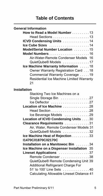
General InformationHow to Read a Model Number . . . . . . . . . 13
Head Sections . . . . . . . . . . . . . . . . . . . 13ICVD Condensing Units . . . . . . . . . . . . . . 14Ice Cube Sizes . . . . . . . . . . . . . . . . . . . . . 14Model/Serial Number Location . . . . . . . . 15Model Numbers . . . . . . . . . . . . . . . . . . . . . 16
Air-Water-Remote Condenser Models 16QuietQube® Models . . . . . . . . . . . . . . 17
Ice Machine Warranty Information . . . . . 18Owner Warranty Registration Card . . . 18Commercial Warranty Coverage . . . . . 19Residential Ice Machine Limited Warranty 21
InstallationStacking Two Ice Machines on a Single Storage Bin . . . . . . . . . . . . . . . 27Ice Deflector . . . . . . . . . . . . . . . . . . . . 27
Location of Ice Machine . . . . . . . . . . . . . . 28Head Section . . . . . . . . . . . . . . . . . . . . 28Ice Beverage Models . . . . . . . . . . . . . 29
Location of ICVD Condensing Units . . . . 30Clearance Requirements . . . . . . . . . . . . . 31
Air, Water, Remote Condenser Models 31QuietQube® Models . . . . . . . . . . . . . . 32
Ice Machine Heat of Rejection . . . . . . . . . 33I1470C/I1870C/I2170C Installation on a Manitowoc Bin . . . . . . . 34Ice Machine on a Dispenser Installation 35Lineset Applications . . . . . . . . . . . . . . . . 37
Remote Condenser . . . . . . . . . . . . . . . 38QuietQube® Remote Condensing Unit 39Additional Refrigerant Charge For 51’ to 100’ Line Sets . . . . . . . . . . . . . . 40Calculating Allowable Lineset Distance 41
6 Part Number Preliminary 6/11
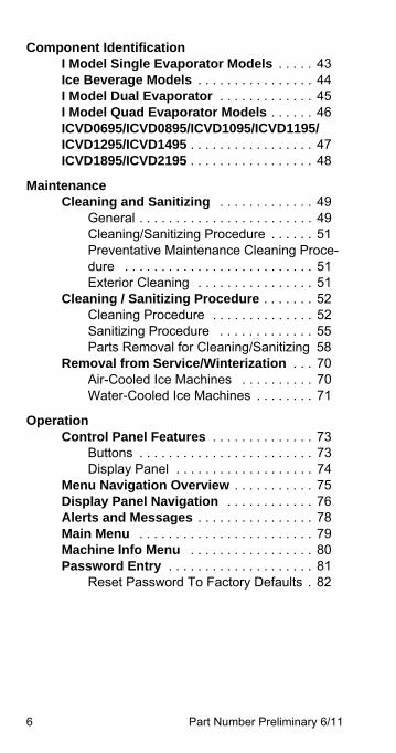
Component IdentificationI Model Single Evaporator Models . . . . . 43Ice Beverage Models . . . . . . . . . . . . . . . . 44I Model Dual Evaporator . . . . . . . . . . . . . 45I Model Quad Evaporator Models . . . . . . 46ICVD0695/ICVD0895/ICVD1095/ICVD1195/ICVD1295/ICVD1495 . . . . . . . . . . . . . . . . . 47ICVD1895/ICVD2195 . . . . . . . . . . . . . . . . . 48
MaintenanceCleaning and Sanitizing . . . . . . . . . . . . . 49
General . . . . . . . . . . . . . . . . . . . . . . . . 49Cleaning/Sanitizing Procedure . . . . . . 51Preventative Maintenance Cleaning Proce-dure . . . . . . . . . . . . . . . . . . . . . . . . . . 51Exterior Cleaning . . . . . . . . . . . . . . . . 51
Cleaning / Sanitizing Procedure . . . . . . . 52Cleaning Procedure . . . . . . . . . . . . . . 52Sanitizing Procedure . . . . . . . . . . . . . 55Parts Removal for Cleaning/Sanitizing 58
Removal from Service/Winterization . . . 70Air-Cooled Ice Machines . . . . . . . . . . 70Water-Cooled Ice Machines . . . . . . . . 71
OperationControl Panel Features . . . . . . . . . . . . . . 73
Buttons . . . . . . . . . . . . . . . . . . . . . . . . 73Display Panel . . . . . . . . . . . . . . . . . . . 74
Menu Navigation Overview . . . . . . . . . . . 75Display Panel Navigation . . . . . . . . . . . . 76Alerts and Messages . . . . . . . . . . . . . . . . 78Main Menu . . . . . . . . . . . . . . . . . . . . . . . . 79Machine Info Menu . . . . . . . . . . . . . . . . . 80Password Entry . . . . . . . . . . . . . . . . . . . . 81
Reset Password To Factory Defaults . 82
Part Number Preliminary 6/11 7
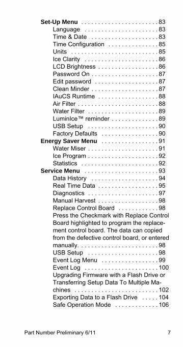
Set-Up Menu . . . . . . . . . . . . . . . . . . . . . . . 83Language . . . . . . . . . . . . . . . . . . . . . . 83Time & Date . . . . . . . . . . . . . . . . . . . . 83Time Configuration . . . . . . . . . . . . . . . 85Units . . . . . . . . . . . . . . . . . . . . . . . . . . 85Ice Clarity . . . . . . . . . . . . . . . . . . . . . . 86LCD Brightness . . . . . . . . . . . . . . . . . . 86Password On . . . . . . . . . . . . . . . . . . . . 87Edit password . . . . . . . . . . . . . . . . . . . 87Clean Minder . . . . . . . . . . . . . . . . . . . . 87IAuCS Runtime . . . . . . . . . . . . . . . . . . 88Air Filter . . . . . . . . . . . . . . . . . . . . . . . . 88Water Filter . . . . . . . . . . . . . . . . . . . . . 89LuminIce™ reminder . . . . . . . . . . . . . . 89USB Setup . . . . . . . . . . . . . . . . . . . . . 90Factory Defaults . . . . . . . . . . . . . . . . . 90
Energy Saver Menu . . . . . . . . . . . . . . . . . 91Water Miser . . . . . . . . . . . . . . . . . . . . . 91Ice Program . . . . . . . . . . . . . . . . . . . . . 92Statistics . . . . . . . . . . . . . . . . . . . . . . . 92
Service Menu . . . . . . . . . . . . . . . . . . . . . . 93Data History . . . . . . . . . . . . . . . . . . . . 94Real Time Data . . . . . . . . . . . . . . . . . . 95Diagnostics . . . . . . . . . . . . . . . . . . . . . 97Manual Harvest . . . . . . . . . . . . . . . . . . 98Replace Control Board . . . . . . . . . . . . 98Press the Checkmark with Replace Control Board highlighted to program the replace-ment control board. The data can copied from the defective control board, or entered manually. . . . . . . . . . . . . . . . . . . . . . . . 98USB Setup . . . . . . . . . . . . . . . . . . . . . 98Event Log Menu . . . . . . . . . . . . . . . . . 99Event Log . . . . . . . . . . . . . . . . . . . . . . 100Upgrading Firmware with a Flash Drive or Transferring Setup Data To Multiple Ma-chines . . . . . . . . . . . . . . . . . . . . . . . . . 102Exporting Data to a Flash Drive . . . . . 104Safe Operation Mode . . . . . . . . . . . . . 106
8 Part Number Preliminary 6/11
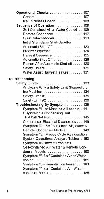
Operational Checks . . . . . . . . . . . . . . . . . 107General . . . . . . . . . . . . . . . . . . . . . . . . 107Ice Thickness Check . . . . . . . . . . . . . 108
Sequence of Operation . . . . . . . . . . . . . . 109Self Contained Air or Water Cooled . . 109Remote Condenser . . . . . . . . . . . . . . 117QuietQube® Models . . . . . . . . . . . . . . 123Initial Start-Up or Start-Up After Automatic Shut-Off . . . . . . . . . . . . . . . 123Freeze Sequence . . . . . . . . . . . . . . . . 124Harvest Sequence . . . . . . . . . . . . . . . 125Automatic Shut-Off . . . . . . . . . . . . . . . 126Restart After Automatic Shut-off . . . . . 126Safety Timers . . . . . . . . . . . . . . . . . . . 131Water Assist Harvest Feature . . . . . . . 131
TroubleshootingSafety Limits . . . . . . . . . . . . . . . . . . . . . . 133
Analyzing Why a Safety Limit Stopped the Ice Machine . . . . . . . . . . . . . . . . . . . . 134Safety Limit #1 . . . . . . . . . . . . . . . . . . 135Safety Limit #2 . . . . . . . . . . . . . . . . . . 136
Troubleshooting By Symptom . . . . . . . . 139Symptom #1 Ice Machine will not run . 141Diagnosing a Condensing Unit That Will Not Run . . . . . . . . . . . . . . . . 145Compressor Electrical Diagnostics . . . 146Symptom #2 - Self-contained Air, Water & Remote Condenser Models . . . . . . . . 148Symptom #2 - Freeze Cycle Refrigeration System Operational Analysis Tables . 150Symptom #3 Harvest Problems Self-contained Air, Water & Remote Con-denser Models . . . . . . . . . . . . . . . . . . 180Symptom #3 Self-Contained Air or Water-cooled . . . . . . . . . . . . . . . . . . . . . . . . . 181Symptom #3 - Remote Condenser . . . 183Symptom #4 Self-Contained Air, Water-cooled or Remote . . . . . . . . . . . . . . . . 185
Part Number Preliminary 6/11 9
Symptom #2 - QuietQube® Remote Condens-ing Unit Models . . . . . . . . . . . . . . . . . . . . . 189
Symptom #2 Low Production, Long Freeze 189QuietQube® Models- Freeze Cycle Refrig-eration System Operational Analysis Tables 191QuietQube® Models - Freeze Cycle Refrig-eration System Operational Analysis Table Procedures . . . . . . . . . . . . . . . . . . . . . 200Symptom #3 Harvest Problems Qui-etQube® Remote Condensing Unit Models 218Symptom #3 QuietQube® Models With ICVD Condensing Units . . . . . . . . . . . 219Symptom #4 QuietQube® Models With ICVD Condensing Units . . . . . . . . . . . 223
Component Check ProceduresElectrical Components . . . . . . . . . . . . . . . 227
Control Board, Display board and Touch Pad . . . . . . . . . . . . . . . . . . . . . . . . . . . 227Control Board Relay Test . . . . . . . . . . 230Upgrading Firmware with a Flash Drive or Transferring Setup Data To Multiple Ma-chines . . . . . . . . . . . . . . . . . . . . . . . . . 231Exporting Data to a Flash Drive . . . . . 233Main Fuse . . . . . . . . . . . . . . . . . . . . . . 235Bin Switch . . . . . . . . . . . . . . . . . . . . . . 236Water Level Control Circuitry . . . . . . . 239Ice Thickness Probe (Harvest Initiation) 243High Pressure Cutout (HPCO) Control 247Low Pressure Cutout (LPCO) Control . 250Fan Cycle Control . . . . . . . . . . . . . . . . 251Thermistors . . . . . . . . . . . . . . . . . . . . . 252Harvest Assist Air Pump . . . . . . . . . . . 255Compressor Electrical Diagnostics . . . 256Diagnosing Start Components . . . . . . 258
10 Part Number Preliminary 6/11
Refrigeration Components . . . . . . . . . . . 263Head Pressure Control Valve . . . . . . . 263Harvest Pressure Regulating (HPR) System Remote Condenser Only . . . . . . . . . . 270Water Regulating Valve . . . . . . . . . . . 273Harvest Pressure Solenoid Valve . . . . 274Suction Accumulator Operation Qui-etQube® Remote Condensing Unit . . 275
Refrigerant Recovery/Evacuation . . . . . 276Self-Contained Model Procedure . . . . 276Remote Condenser Model Procedure 280QuietQube® Models . . . . . . . . . . . . . . 286Connections . . . . . . . . . . . . . . . . . . . . 287Recovery/Evacuation Procedures . . . 289Charging Procedures . . . . . . . . . . . . . 290
System Contamination Clean-Up . . . . . . 292Determining Severity Of Contamination 292Cleanup Procedure . . . . . . . . . . . . . . 294Replacing Pressure Controls Without Re-moving Refrigerant Charge . . . . . . . . 297Liquid Line Filter-Driers . . . . . . . . . . . 299Suction Filter . . . . . . . . . . . . . . . . . . . 300Total System Refrigerant Charge . . . . 301
Part Number Preliminary 6/11 11
ChartsCycle Times/24-Hour Ice Production/Refrigerant Pressure Charts . . . . . . . . . . 307
I0300 Series . . . . . . . . . . . . . . . . . . . . 308I0320 Series . . . . . . . . . . . . . . . . . . . . 310I0450 Series . . . . . . . . . . . . . . . . . . . . 312I0500 Series . . . . . . . . . . . . . . . . . . . . 314I0520 Series . . . . . . . . . . . . . . . . . . . . 317I0600 Series . . . . . . . . . . . . . . . . . . . . 319I0680C/ICVD0695 . . . . . . . . . . . . . . . . 322IB0690C/ICVD695 . . . . . . . . . . . . . . . . 323I0850 Series . . . . . . . . . . . . . . . . . . . . 324I0870C . . . . . . . . . . . . . . . . . . . . . . . . . 327I1000 Series . . . . . . . . . . . . . . . . . . . . 328I1200 Series . . . . . . . . . . . . . . . . . . . . 333
DiagramsWiring Diagrams . . . . . . . . . . . . . . . . . . . . 335
Wiring Diagram Legend . . . . . . . . . . . . 335I0300/I0320/I0450/I0500/I0520 . . . . . . 336I0500 . . . . . . . . . . . . . . . . . . . . . . . . . . 337I0600/I0850/I1000/I1200 . . . . . . . . . . . 338I0600/I0850/I1000 . . . . . . . . . . . . . . . . 339I0670C/I0870C/I1070C/I1270C . . . . . . 340IB0690C/IB0890C/IB1090C . . . . . . . . 341I1400/I1800 . . . . . . . . . . . . . . . . . . . . . 342I1400/I1800 . . . . . . . . . . . . . . . . . . . . . 343
Electronic Control Board . . . . . . . . . . . . . 344
Refrigeration Tubing Schematics . . . . . . 345Self-Contained Air or Water -Cooled . . 345Remote Condenser Models . . . . . . . . . 346Remote Condensing Unit Models . . . . 347IB Models . . . . . . . . . . . . . . . . . . . . . . 348

12 Part Number Preliminary 6/11
This Page Intentionally Left Blank
Part Number Preliminary 6/11 13
General Information
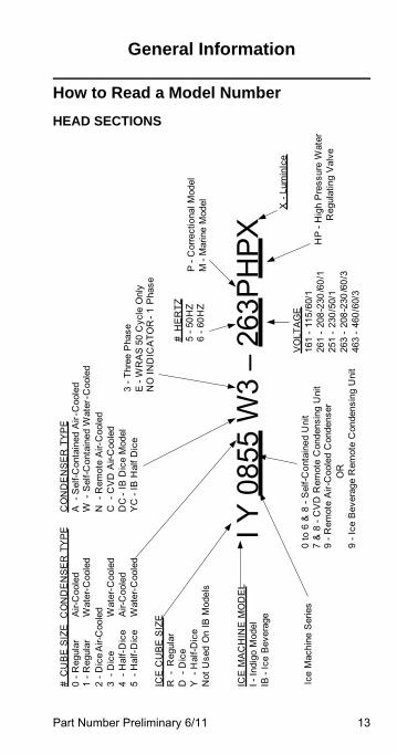
How to Read a Model Number
HEAD SECTIONS
I Y 0
855
W3
–26
3PH
PXIC
E M
AC
HIN
E M
OD
EL
I -In
digo
Mod
elIB
-Ic
e B
ever
age
# C
UB
E S
IZE
CO
ND
EN
SE
R T
YP
E0
-Reg
ular
Air-
Coo
led
1 -R
egul
arW
ater
-Coo
led
2 -D
ice
Air-
Coo
led
3 -
Dic
eW
ater
-Coo
led
4 -
Hal
f-D
ice
Air-
Coo
led
5 -
Hal
f-D
ice
Wat
er-C
oole
d
0 to
6 &
8 -
Sel
f-Con
tain
ed U
nit
7 &
8 -
CV
D R
emot
e C
onde
nsin
g U
nit
9 -R
emot
e A
ir-C
oole
d C
onde
nser
O
R9
-Ice
Bev
erag
e R
emot
e C
onde
nsin
g U
nit
ICE
CU
BE
SIZ
ER
-R
egul
arD
-D
ice
Y -
Hal
f-Dic
eN
ot U
sed
On
IB M
odel
s
Ice
Mac
hine
Ser
ies
CO
ND
EN
SE
R T
YP
EA
-S
elf-C
onta
ined
Air
-Coo
led
W -
Sel
f-Con
tain
ed W
ater
-Coo
led
N -
Rem
ote
Air-
Coo
led
C -
CV
D A
ir-C
oole
dD
C -
IB D
ice
Mod
elY
C -
IB H
alf D
ice
3 -T
hree
Pha
seE
-W
RA
S 5
0 C
ycle
Onl
yN
O IN
DIC
ATO
R -
1 P
hase
VO
LTA
GE
161
-11
5/60
/126
1 -
208-
230
/60/
125
1 -
230/
50/1
263
-20
8-23
0/6
0/3
463
-46
0/60
/3
# H
ER
TZ5
-50H
Z6
-60H
Z
HP
-H
igh
Pre
ssur
e W
ater
Reg
ulat
ing
Val
ve
P -
Cor
rect
iona
l Mod
elM
-M
arin
e M
odel X -
Lum
inIc
e
14 Part Number Preliminary 6/11
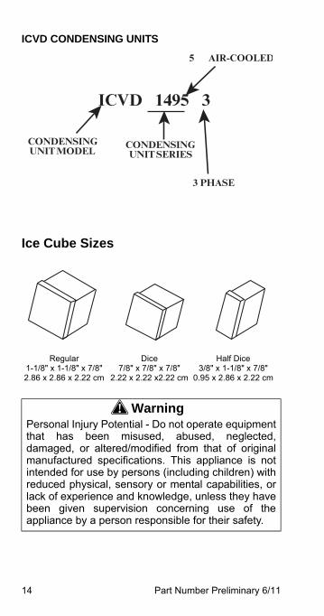
ICVD CONDENSING UNITS
Ice Cube Sizes
Regular1-1/8" x 1-1/8" x 7/8"2.86 x 2.86 x 2.22 cm
Dice7/8" x 7/8" x 7/8"
2.22 x 2.22 x2.22 cm
Half Dice3/8" x 1-1/8" x 7/8"
0.95 x 2.86 x 2.22 cm
! WarningPersonal Injury Potential - Do not operate equipmentthat has been misused, abused, neglected,damaged, or altered/modified from that of originalmanufactured specifications. This appliance is notintended for use by persons (including children) withreduced physical, sensory or mental capabilities, orlack of experience and knowledge, unless they havebeen given supervision concerning use of theappliance by a person responsible for their safety.
ICVD 1495 3
CONDENSINGUNIT MODEL
3 PHASE
CONDENSING UNIT SERIES
5 AIR-COOLED
Part Number Preliminary 6/11 15
Model/Serial Number LocationThese numbers are required when requesting information from your local Manitowoc Distributor, service representative, or Manitowoc Ice, Inc. The model and serial number are listed on the OWNER WARRANTY REGISTRATION CARD. They are also listed on the MODEL/SERIAL NUMBER DECAL affixed to the front and rear of the ice machine.
! WarningAll Manitowoc ice machines require the icestorage system (bin, dispenser, etc.) toincorporate an ice deflector.Prior to using a non-Manitowoc ice storagesystem with other Manitowoc ice machines,contact the manufacturer to assure their icedeflector is compatible with Manitowoc icemachines.
16 Part Number Preliminary 6/11
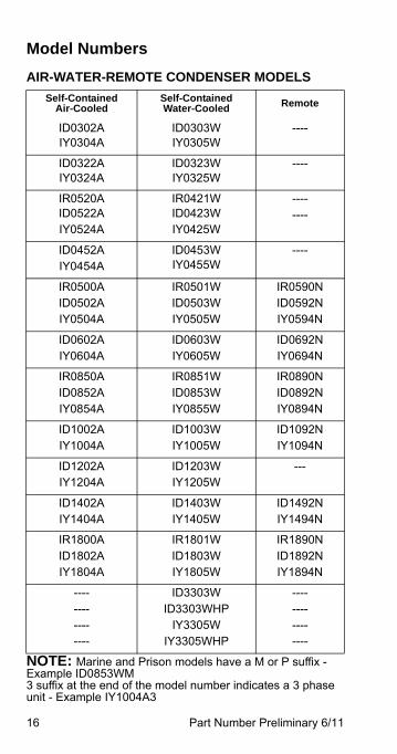
Model Numbers
AIR-WATER-REMOTE CONDENSER MODELS
NOTE: Marine and Prison models have a M or P suffix - Example ID0853WM3 suffix at the end of the model number indicates a 3 phase unit - Example IY1004A3
Self-Contained Air-Cooled
Self-Contained Water-Cooled Remote
ID0302AIY0304A
ID0303WIY0305W
----
ID0322AIY0324A
ID0323WIY0325W
----
IR0520AID0522AIY0524A
IR0421WID0423WIY0425W
--------
ID0452AIY0454A
ID0453WIY0455W
----
IR0500A ID0502AIY0504A
IR0501WID0503WIY0505W
IR0590NID0592NIY0594N
ID0602AIY0604A
ID0603WIY0605W
ID0692NIY0694N
IR0850AID0852AIY0854A
IR0851WID0853WIY0855W
IR0890NID0892NIY0894N
ID1002AIY1004A
ID1003WIY1005W
ID1092NIY1094N
ID1202AIY1204A
ID1203WIY1205W
---
ID1402AIY1404A
ID1403WIY1405W
ID1492NIY1494N
IR1800AID1802AIY1804A
IR1801WID1803WIY1805W
IR1890NID1892NIY1894N
----------------
ID3303WID3303WHP
IY3305WIY3305WHP
----------------
Part Number Preliminary 6/11 17
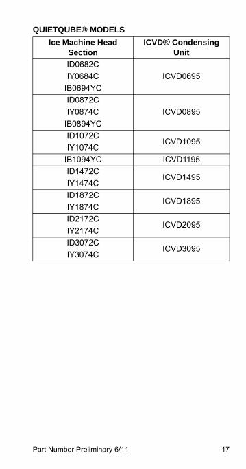
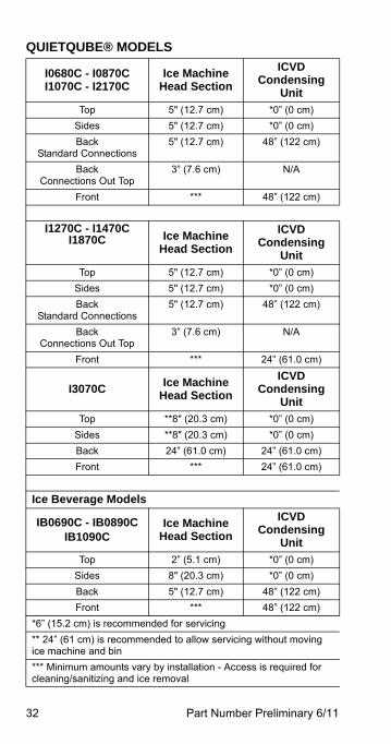
QUIETQUBE® MODELS
Ice Machine Head Section
ICVD® Condensing Unit
ID0682C
IY0684C
IB0694YC
ICVD0695
ID0872C
IY0874C
IB0894YC
ICVD0895
ID1072C
IY1074CICVD1095
IB1094YC ICVD1195
ID1472C
IY1474CICVD1495
ID1872C
IY1874CICVD1895
ID2172C
IY2174CICVD2095
ID3072C
IY3074CICVD3095
18 Part Number Preliminary 6/11
Ice Machine Warranty Information
OWNER WARRANTY REGISTRATION CARDWarranty coverage begins the day the ice machine is installed.
If the OWNER WARRANTY REGISTRATION CARD is not returned, Manitowoc will use the born on date recorded in the control board or the date of sale to the Manitowoc Distributor as the first day of warranty coverage for your new ice machine.
ImportantComplete and mail the OWNER WARRANTYREGISTRATION CARD as soon as possible tovalidate the installation date.
Part Number Preliminary 6/11 19
COMMERCIAL WARRANTY COVERAGEManitowoc Ice, (hereinafter referred to as the "COMPANY") warrants for a period of thirty-six months from the installation date (except as limited below) that new ice machines manufactured by the COMPANY shall be free of defects in material or workmanship under normal and proper use and maintenance as specified by the COMPANY and upon proper installation and start-up in accordance with the instruction manual supplied with the ice machine.
The COMPANY'S warranty hereunder with respect to the compressor shall apply for an additional twenty-four months, excluding all labor charges, and with respect to the evaporator for an additional twenty-four months, including labor charges.
The obligation of the COMPANY under this warranty is limited to the repair or replacement of parts, components, or assemblies that in the opinion of the COMPANY are defective. This warranty is further limited to the cost of parts, components or assemblies and standard straight time labor charges at the servicing location. Time and hourly rate schedules, as published from time to time by the COMPANY, apply to all service procedures.
Additional expenses including without limitation, travel time, overtime premium, material cost, accessing or removal of the ice machine, or shipping are the responsibility of the owner, along with all maintenance, adjustments, cleaning, and ice purchases.
Labor covered under this warranty must be performed by a COMPANY Contracted Service Representative or a refrigeration service agency as qualified and authorized by the COMPANY'S local Distributor.
The COMPANY'S liability under this warranty shall in no event be greater than the actual purchase price paid by customer for the ice machine.
20 Part Number Preliminary 6/11
The foregoing warranty shall not apply to (1) any part or assembly that has been altered, modified, or changed; (2) any part or assembly that has been subjected to misuse, abuse, neglect, or accidents; (3) any ice machine that has been installed and/or maintained inconsistent with the technical instructions provided by the COMPANY; or (4) any ice machine initially installed more than five years from the serial number production date. This warranty shall not apply if the Ice Machine's refrigeration system is modified with a condenser, heat reclaim device, or parts and assemblies other than those manufactured by the COMPANY, unless the COMPANY approves these modifications for specific locations in writing.
THIS WARRANTY IS IN LIEU OF ALL OTHER WARRANTIES OR GUARANTEES OF ANYKIND, EXPRESSED OR IMPLIED, INCLUDING ANY IMPLIED WARRANTY OF MERCHANTABILITYOR FITNESS FOR A PARTICULAR PURPOSE.
In no event shall the COMPANY be liable for any special, indirect, incidental or consequential damages. Upon the expiration of the warranty period, the COMPANY'S liability under this warranty shall terminate. The foregoing warranty shall constitute the sole liability of the COMPANY and the exclusive remedy of the customer or user.
To secure prompt and continuing warranty service, the warranty registration card must be completed and sent to the COMPANY within five (5) days from the installation date.
To obtain warranty service or information regarding your Product, please contact us at:
MANITOWOC ICE
2110 So. 26th St. P.O. Box 1720,
Manitowoc, WI 54221-1720
Telephone: 920-682-0161 Fax: 920-683-7585
www.manitowocice.com
Part Number Preliminary 6/11 21
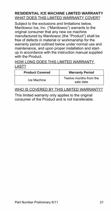
RESIDENTIAL ICE MACHINE LIMITED WARRANTYWHAT DOES THIS LIMITED WARRANTY COVER?
Subject to the exclusions and limitations below, Manitowoc Ice, Inc. (“Manitowoc”) warrants to the original consumer that any new ice machine manufactured by Manitowoc (the “Product”) shall be free of defects in material or workmanship for the warranty period outlined below under normal use and maintenance, and upon proper installation and start-up in accordance with the instruction manual supplied with the Product.
HOW LONG DOES THIS LIMITED WARRANTY LAST?
WHO IS COVERED BY THIS LIMITED WARRANTY?
This limited warranty only applies to the original consumer of the Product and is not transferable.
Product Covered Warranty Period
Ice MachineTwelve months from the
sale date
22 Part Number Preliminary 6/11
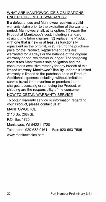
WHAT ARE MANITOWOC ICE’S OBLIGATIONS UNDER THIS LIMITED WARRANTY?
If a defect arises and Manitowoc receives a valid warranty claim prior to the expiration of the warranty period, Manitowoc shall, at its option: (1) repair the Product at Manitowoc’s cost, including standard straight time labor charges, (2) replace the Product with one that is new or at least as functionally equivalent as the original, or (3) refund the purchase price for the Product. Replacement parts are warranted for 90 days or the balance of the original warranty period, whichever is longer. The foregoing constitutes Manitowoc’s sole obligation and the consumer’s exclusive remedy for any breach of this limited warranty. Manitowoc’s liability under this limited warranty is limited to the purchase price of Product. Additional expenses including, without limitation, service travel time, overtime or premium labor charges, accessing or removing the Product, or shipping are the responsibility of the consumer.
HOW TO OBTAIN WARRANTY SERVICE
To obtain warranty service or information regarding your Product, please contact us at:
MANITOWOC ICE
2110 So. 26th St.
P.O. Box 1720,
Manitowoc, WI 54221-1720
Telephone: 920-682-0161 Fax: 920-683-7585
www.manitowocice.com
Part Number Preliminary 6/11 23
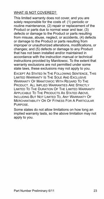
WHAT IS NOT COVERED?
This limited warranty does not cover, and you are solely responsible for the costs of: (1) periodic or routine maintenance, (2) repair or replacement of the Product or parts due to normal wear and tear, (3) defects or damage to the Product or parts resulting from misuse, abuse, neglect, or accidents, (4) defects or damage to the Product or parts resulting from improper or unauthorized alterations, modifications, or changes; and (5) defects or damage to any Product that has not been installed and/or maintained in accordance with the instruction manual or technical instructions provided by Manitowoc. To the extent that warranty exclusions are not permitted under some state laws, these exclusions may not apply to you.
EXCEPT AS STATED IN THE FOLLOWING SENTENCE, THIS LIMITED WARRANTY IS THE SOLE AND EXCLUSIVE WARRANTY OF MANITOWOC WITH REGARD TO THE PRODUCT. ALL IMPLIED WARRANTIES ARE STRICTLY LIMITED TO THE DURATION OF THE LIMITED WARRANTY APPLICABLE TO THE PRODUCTS AS STATED ABOVE, INCLUDING BUT NOT LIMITED TO, ANY WARRANTY OF MERCHANTABILITY OR OF FITNESS FOR A PARTICULAR PURPOSE.
Some states do not allow limitations on how long an implied warranty lasts, so the above limitation may not apply to you.
24 Part Number Preliminary 6/11
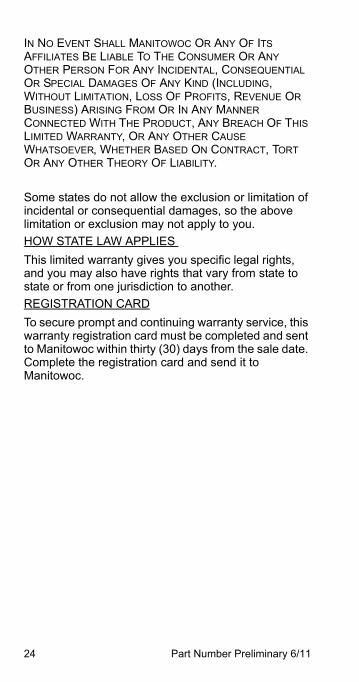
IN NO EVENT SHALL MANITOWOC OR ANY OF ITS AFFILIATES BE LIABLE TO THE CONSUMER OR ANY OTHER PERSON FOR ANY INCIDENTAL, CONSEQUENTIAL OR SPECIAL DAMAGES OF ANY KIND (INCLUDING, WITHOUT LIMITATION, LOSS OF PROFITS, REVENUE OR BUSINESS) ARISING FROM OR IN ANY MANNER CONNECTED WITH THE PRODUCT, ANY BREACH OF THIS LIMITED WARRANTY, OR ANY OTHER CAUSE WHATSOEVER, WHETHER BASED ON CONTRACT, TORT OR ANY OTHER THEORY OF LIABILITY.
Some states do not allow the exclusion or limitation of incidental or consequential damages, so the above limitation or exclusion may not apply to you.
HOW STATE LAW APPLIES
This limited warranty gives you specific legal rights, and you may also have rights that vary from state to state or from one jurisdiction to another.
REGISTRATION CARD
To secure prompt and continuing warranty service, this warranty registration card must be completed and sent to Manitowoc within thirty (30) days from the sale date. Complete the registration card and send it to Manitowoc.

Part Number Preliminary 6/11 25
This Page Intentionally Left Blank

26 Part Number Preliminary 6/11
This Page Intentionally Left Blank
Part Number Preliminary 6/11 27
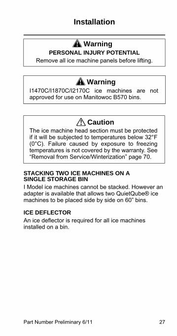
Installation
STACKING TWO ICE MACHINES ON A SINGLE STORAGE BINI Model ice machines cannot be stacked. However an adapter is available that allows two QuietQube® ice machines to be placed side by side on 60” bins.
ICE DEFLECTORAn ice deflector is required for all ice machines installed on a bin.
! WarningPERSONAL INJURY POTENTIAL
Remove all ice machine panels before lifting.
! WarningI1470C/I1870C/I2170C ice machines are notapproved for use on Manitowoc B570 bins.
! CautionThe ice machine head section must be protectedif it will be subjected to temperatures below 32°F(0°C). Failure caused by exposure to freezingtemperatures is not covered by the warranty. See“Removal from Service/Winterization” page 70.
28 Part Number Preliminary 6/11
Location of Ice Machine
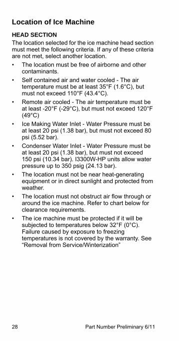
HEAD SECTIONThe location selected for the ice machine head section must meet the following criteria. If any of these criteria are not met, select another location.
• The location must be free of airborne and other contaminants.
• Self contained air and water cooled - The air temperature must be at least 35°F (1.6°C), but must not exceed 110°F (43.4°C).
• Remote air cooled - The air temperature must be at least -20°F (-29°C), but must not exceed 120°F (49°C)
• Ice Making Water Inlet - Water Pressure must be at least 20 psi (1.38 bar), but must not exceed 80 psi (5.52 bar).
• Condenser Water Inlet - Water Pressure must be at least 20 psi (1.38 bar), but must not exceed 150 psi (10.34 bar). I3300W-HP units allow water pressure up to 350 psig (24.13 bar).
• The location must not be near heat-generating equipment or in direct sunlight and protected from weather.
• The location must not obstruct air flow through or around the ice machine. Refer to chart below for clearance requirements.
• The ice machine must be protected if it will be subjected to temperatures below 32°F (0°C). Failure caused by exposure to freezing temperatures is not covered by the warranty. See “Removal from Service/Winterization”
Part Number Preliminary 6/11 29
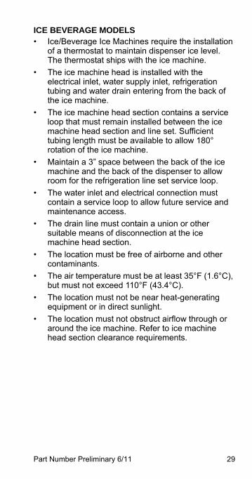
ICE BEVERAGE MODELS• Ice/Beverage Ice Machines require the installation
of a thermostat to maintain dispenser ice level. The thermostat ships with the ice machine.
• The ice machine head is installed with the electrical inlet, water supply inlet, refrigeration tubing and water drain entering from the back of the ice machine.
• The ice machine head section contains a service loop that must remain installed between the ice machine head section and line set. Sufficient tubing length must be available to allow 180° rotation of the ice machine.
• Maintain a 3” space between the back of the ice machine and the back of the dispenser to allow room for the refrigeration line set service loop.
• The water inlet and electrical connection must contain a service loop to allow future service and maintenance access.
• The drain line must contain a union or other suitable means of disconnection at the ice machine head section.
• The location must be free of airborne and other contaminants.
• The air temperature must be at least 35°F (1.6°C), but must not exceed 110°F (43.4°C).
• The location must not be near heat-generating equipment or in direct sunlight.
• The location must not obstruct airflow through or around the ice machine. Refer to ice machine head section clearance requirements.
30 Part Number Preliminary 6/11
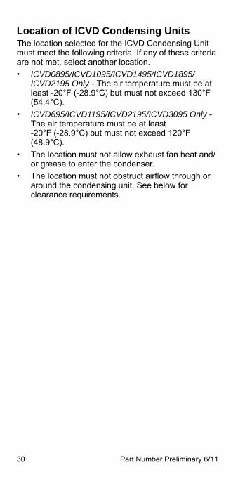
Location of ICVD Condensing UnitsThe location selected for the ICVD Condensing Unit must meet the following criteria. If any of these criteria are not met, select another location.
• ICVD0895/ICVD1095/ICVD1495/ICVD1895/ICVD2195 Only - The air temperature must be at least -20°F (-28.9°C) but must not exceed 130°F (54.4°C).
• ICVD695/ICVD1195/ICVD2195/ICVD3095 Only - The air temperature must be at least -20°F (-28.9°C) but must not exceed 120°F (48.9°C).
• The location must not allow exhaust fan heat and/or grease to enter the condenser.
• The location must not obstruct airflow through or around the condensing unit. See below for clearance requirements.
Part Number Preliminary 6/11 31
Clearance Requirements
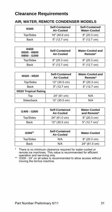
AIR, WATER, REMOTE CONDENSER MODELS
I0300Self-Contained
Air-CooledSelf-Contained Water-Cooled
Top/Sides 16" (40.6 cm) 8" (20.3 cm)
Back 5" (12.7 cm) 5" (12.7 cm)
I0450I0500 - I0600I0850 - I1000
Self-Contained Air-Cooled
Water-Cooled and Remote*
Top/Sides 8" (20.3 cm) 8" (20.3 cm)
Back 5" (12.7 cm) 5" (12.7 cm)
I0320 - I0520Self-Contained
Air-CooledWater-Cooled and
Remote*
Top/Sides 12" (30.5 cm) 8" (20.3 cm)
Back 5" (12.7 cm) 5" (12.7 cm)
I0520 Tropical Rating
Top 24” (61 cm) N/A
Sides/back 12” (30.5 cm) N/A
I1400 - I1800Self-Contained
Air-CooledWater-Cooledand Remote*
Top/Sides 24" (61.0 cm) 8" (20.3 cm)
Back 12" (30.5 cm) 5" (12.7 cm)*
* There is no minimum clearance required for water-cooled or remote ice machines. This value is recommended for efficient operation and servicing only.
I3300**
** I3300 - 24” on all sides is recommended to allow access without moving the bin/ice machine.
Self-Contained Air-Cooled
Water-Cooled
Top/Sides N/A 8" (20.3 cm)
Back N/A 24" (61.0 cm)
32 Part Number Preliminary 6/11
QUIETQUBE® MODELS
I0680C - I0870C I1070C - I2170C
Ice Machine Head Section
ICVD Condensing
Unit
Top 5" (12.7 cm) *0” (0 cm)
Sides 5" (12.7 cm) *0” (0 cm)
BackStandard Connections
5" (12.7 cm) 48” (122 cm)
BackConnections Out Top
3” (7.6 cm) N/A
Front *** 48” (122 cm)
I1270C - I1470C I1870C Ice Machine
Head Section
ICVD Condensing
Unit
Top 5" (12.7 cm) *0” (0 cm)
Sides 5" (12.7 cm) *0” (0 cm)
BackStandard Connections
5" (12.7 cm) 48” (122 cm)
BackConnections Out Top
3” (7.6 cm) N/A
Front *** 24” (61.0 cm)
I3070C Ice Machine
Head Section
ICVD Condensing
Unit
Top **8" (20.3 cm) *0” (0 cm)
Sides **8" (20.3 cm) *0” (0 cm)
Back 24” (61.0 cm) 24” (61.0 cm)
Front *** 24” (61.0 cm)
Ice Beverage Models
IB0690C - IB0890CIB1090C
Ice Machine Head Section
ICVD Condensing
Unit
Top 2” (5.1 cm) *0” (0 cm)
Sides 8" (20.3 cm) *0” (0 cm)
Back 5" (12.7 cm) 48” (122 cm)
Front *** 48” (122 cm)
*6” (15.2 cm) is recommended for servicing
** 24” (61 cm) is recommended to allow servicing without moving ice machine and bin
*** Minimum amounts vary by installation - Access is required for cleaning/sanitizing and ice removal
Part Number Preliminary 6/11 33
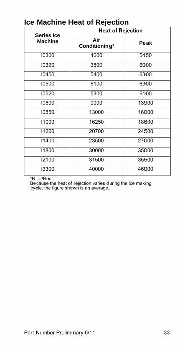
Ice Machine Heat of Rejection
Series Ice Machine
Heat of Rejection
Air Conditioning*
Peak
I0300 4600 5450
I0320 3800 6000
I0450 5400 6300
I0500 6100 6900
I0520 5300 6100
I0600 9000 13900
I0850 13000 16000
I1000 16250 18600
I1200 20700 24500
I1400 23500 27000
I1800 30000 35000
I2100 31500 35500
I3300 40000 46000
*BTU/HourBecause the heat of rejection varies during the ice making cycle, the figure shown is an average.
34 Part Number Preliminary 6/11
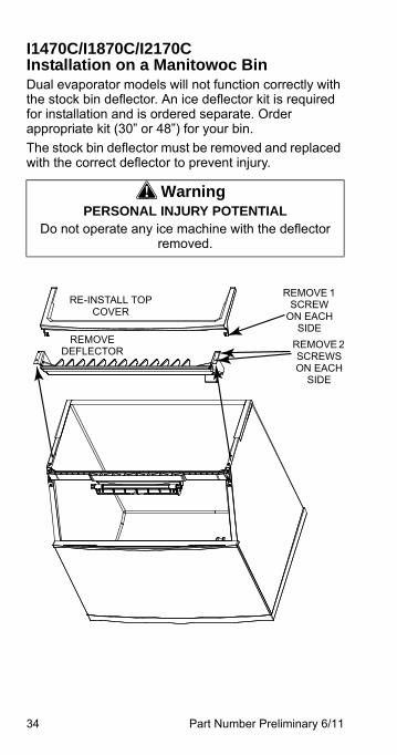
I1470C/I1870C/I2170C Installation on a Manitowoc BinDual evaporator models will not function correctly with the stock bin deflector. An ice deflector kit is required for installation and is ordered separate. Order appropriate kit (30” or 48”) for your bin.
The stock bin deflector must be removed and replaced with the correct deflector to prevent injury.
! WarningPERSONAL INJURY POTENTIAL
Do not operate any ice machine with the deflector removed.
RE-INSTALL TOP COVER
REMOVE 1 SCREW
ON EACH SIDE
REMOVE DEFLECTOR
REMOVE 2SCREWS ON EACH
SIDE
Part Number Preliminary 6/11 35
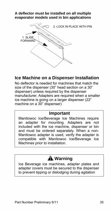
A deflector must be installed on all multiple evaporator models used in bin applications
Ice Machine on a Dispenser InstallationNo deflector is needed for machines that match the size of the dispenser (30” head section on a 30” dispenser) unless required by the dispenser manufacturer. Adapters are required when a smaller ice machine is going on a larger dispenser (22” machine on a 30” dispenser)
.
ImportantManitowoc Ice/Beverage Ice Machines requirean adapter for mounting. Adapters are notincluded with the ice machine, dispenser or binand must be ordered separately. When a non-Manitowoc adapter is used, verify the adapter iscompatible with Manitowoc Ice/Beverage IceMachines prior to installation.
! WarningIce Beverage ice machines, adapter plates andadapter covers must be secured to the dispenserto prevent tipping or dislodging during agitation
1. SLIDE FORWARD
2. LOCK IN PLACE WITH PIN

36 Part Number Preliminary 6/11
This Page Intentionally Left Blank
Part Number Preliminary 6/11 37
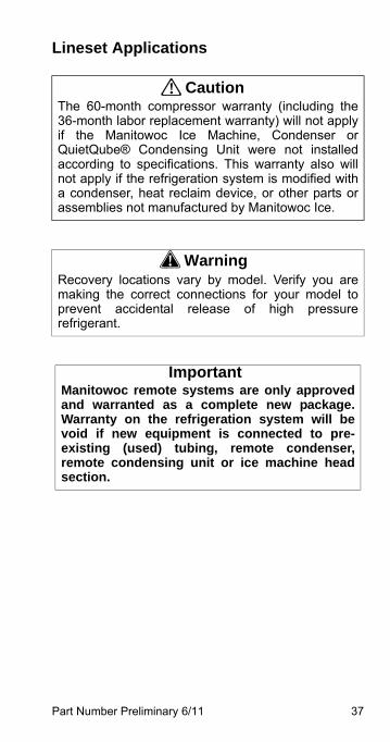
Lineset Applications
! CautionThe 60-month compressor warranty (including the36-month labor replacement warranty) will not applyif the Manitowoc Ice Machine, Condenser orQuietQube® Condensing Unit were not installedaccording to specifications. This warranty also willnot apply if the refrigeration system is modified witha condenser, heat reclaim device, or other parts orassemblies not manufactured by Manitowoc Ice.
! WarningRecovery locations vary by model. Verify you aremaking the correct connections for your model toprevent accidental release of high pressurerefrigerant.
ImportantManitowoc remote systems are only approvedand warranted as a complete new package.Warranty on the refrigeration system will bevoid if new equipment is connected to pre-existing (used) tubing, remote condenser,remote condensing unit or ice machine headsection.
38 Part Number Preliminary 6/11
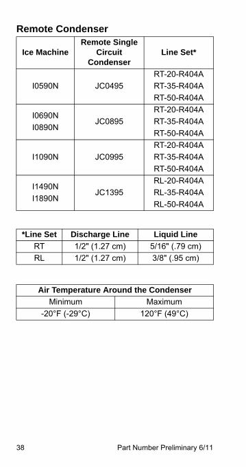
Remote Condenser
Ice MachineRemote Single
Circuit Condenser
Line Set*
I0590N JC0495
RT-20-R404A
RT-35-R404A
RT-50-R404A
I0690N
I0890NJC0895
RT-20-R404A
RT-35-R404A
RT-50-R404A
I1090N JC0995
RT-20-R404A
RT-35-R404A
RT-50-R404A
I1490N
I1890NJC1395
RL-20-R404A
RL-35-R404A
RL-50-R404A
*Line Set Discharge Line Liquid Line
RT 1/2" (1.27 cm) 5/16" (.79 cm)
RL 1/2" (1.27 cm) 3/8" (.95 cm)
Air Temperature Around the Condenser
Minimum Maximum
-20°F (-29°C) 120°F (49°C)
Part Number Preliminary 6/11 39
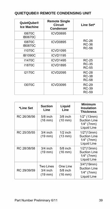
QUIETQUBE® REMOTE CONDENSING UNIT
QuietQube®Ice Machine
Remote Single Circuit
CondenserLine Set*
I0670CIB0670C
ICVD0695
RC-26RC-36RC-56
I0870CIB0870C
ICVD0895
I1070C ICVD1095
IB1090C ICVD1195
I1470C ICVD1495 RC-25RC-35RC-55
I1870C ICVD1895
I2170C ICVD2095 RC-28RC-38RC-58
I3070C ICVD3095 RC-29RC-39RC-59
*Line SetSuction
LineLiquid Line
Minimum Insulation Thickness
RC 26/36/56 5/8 inch(16 mm)
3/8 inch(10 mm)
1/2" (13mm) Suction Line1/4" (7mm) Liquid Line
RC 25/35/55 3/4 inch(19 mm)
1/2 inch(13 mm)
1/2"(13mm) Suction Line1/4" (7mm) Liquid Line
RC 28/38/58 3/4 inch(19 mm)
5/8 inch(16 mm)
1/2"(13mm) Suction Line1/4" (7mm) Liquid Line
RC 29/39/59Two Lines 3/4 inch(19 mm)
One Line 5/8 inch(16 mm)
3/4"(19mm) Suction Line1/4" (7mm) Liquid Line
40 Part Number Preliminary 6/11
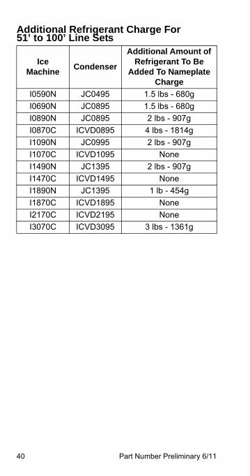
Additional Refrigerant Charge For 51’ to 100’ Line Sets
Ice Machine
Condenser
Additional Amount of Refrigerant To Be
Added To Nameplate Charge
I0590N JC0495 1.5 lbs - 680g
I0690N JC0895 1.5 lbs - 680g
I0890N JC0895 2 lbs - 907g
I0870C ICVD0895 4 lbs - 1814g
I1090N JC0995 2 lbs - 907g
I1070C ICVD1095 None
I1490N JC1395 2 lbs - 907g
I1470C ICVD1495 None
I1890N JC1395 1 lb - 454g
I1870C ICVD1895 None
I2170C ICVD2195 None
I3070C ICVD3095 3 lbs - 1361g
Part Number Preliminary 6/11 41
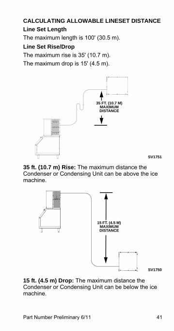
CALCULATING ALLOWABLE LINESET DISTANCE
Line Set Length
The maximum length is 100' (30.5 m).
Line Set Rise/Drop
The maximum rise is 35' (10.7 m).
The maximum drop is 15' (4.5 m).
35 ft. (10.7 m) Rise: The maximum distance the Condenser or Condensing Unit can be above the ice machine.
15 ft. (4.5 m) Drop: The maximum distance the Condenser or Condensing Unit can be below the ice machine.
SV1751
35 FT. (10.7 M) MAXIMUM DISTANCE
SV1750
15 FT. (4.5 M) MAXIMUM DISTANCE
42 Part Number Preliminary 6/11
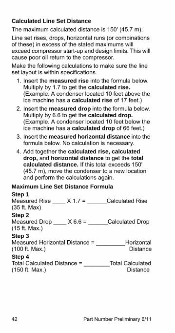
Calculated Line Set Distance
The maximum calculated distance is 150' (45.7 m).
Line set rises, drops, horizontal runs (or combinations of these) in excess of the stated maximums will exceed compressor start-up and design limits. This will cause poor oil return to the compressor.
Make the following calculations to make sure the line set layout is within specifications.
1. Insert the measured rise into the formula below. Multiply by 1.7 to get the calculated rise.(Example: A condenser located 10 feet above the ice machine has a calculated rise of 17 feet.)
2. Insert the measured drop into the formula below. Multiply by 6.6 to get the calculated drop.(Example. A condenser located 10 feet below the ice machine has a calculated drop of 66 feet.)
3. Insert the measured horizontal distance into the formula below. No calculation is necessary.
4. Add together the calculated rise, calculated drop, and horizontal distance to get the total calculated distance. If this total exceeds 150' (45.7 m), move the condenser to a new location and perform the calculations again.
Maximum Line Set Distance FormulaStep 1 Measured Rise ____ X 1.7 = ______Calculated Rise(35 ft. Max)Step 2 Measured Drop ____ X 6.6 = ______Calculated Drop(15 ft. Max.)Step 3 Measured Horizontal Distance = _________Horizontal(100 ft. Max.) DistanceStep 4 Total Calculated Distance = ________Total Calculated(150 ft. Max.) Distance
Part Number Preliminary 6/11 43
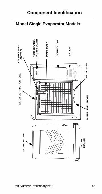
Component Identification
I Model Single Evaporator Models
Off
On / Off Mode
[ ]
!
WA
TE
R D
IST
RIB
UT
ION
TU
BE
WA
TE
R
TR
OU
GH
ICE
TH
ICK
NE
SS
C
ON
TR
OL
RE
FR
IGE
RA
TIO
NA
CC
ES
S V
ALV
ES
EV
AP
OR
AT
OR
DIS
PL
AY
WA
TE
R P
UM
PW
AT
ER
LE
VE
L P
RO
BE
CO
NT
RO
L B
OX
WA
TE
R C
UR
TAIN
44 Part Number Preliminary 6/11
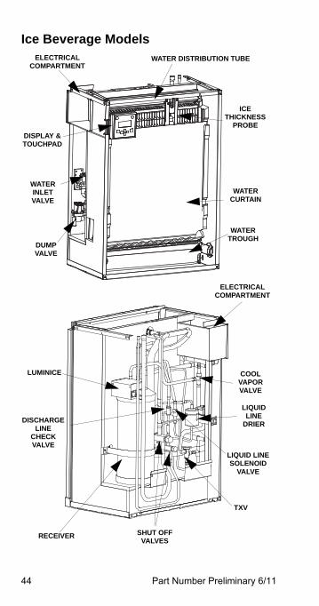
Ice Beverage ModelsWATER DISTRIBUTION TUBE
WATERCURTAIN
DUMPVALVE
SHUT OFFVALVES
ELECTRICALCOMPARTMENT
ICETHICKNESS
PROBE
WATERTROUGH
COOLVAPORVALVE
LIQUID LINE SOLENOID
VALVE
RECEIVER
LIQUIDLINE
DRIER
WATERINLETVALVE
TXV
ELECTRICALCOMPARTMENT
DISCHARGELINE
CHECKVALVE
DISPLAY & TOUCHPAD
LUMINICE
Part Number Preliminary 6/11 45
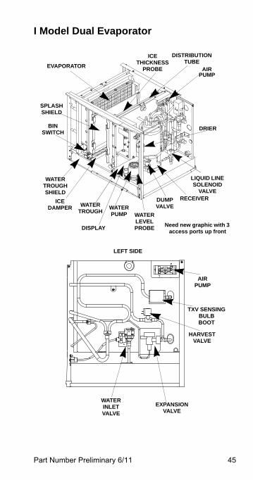
I Model Dual Evaporator
AIRPUMP
DISTRIBUTION TUBE
ICE THICKNESS
PROBEEVAPORATOR
SPLASHSHIELD
BIN SWITCH
WATER TROUGH SHIELD
ICE DAMPER WATER
TROUGHWATER PUMP
DUMP VALVE
RECEIVER
LIQUID LINE SOLENOID
VALVE
DRIER
DISPLAY
WATER LEVEL PROBE
LEFT SIDE
HARVEST VALVE
TXV SENSING BULBBOOT
AIRPUMP
EXPANSION VALVE
WATER INLET VALVE
Need new graphic with 3 access ports up front
46 Part Number Preliminary 6/11
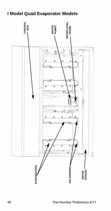
I Model Quad Evaporator Models
WA
TE
R
PU
MP
S
WA
TE
R L
EV
EL
P
RO
BE
EV
AP
OR
AT
OR
S
WA
TE
R
TR
OU
GH
CO
NT
RO
L
BO
X
ICE
DA
MP
ER
S
Part Number Preliminary 6/11 47
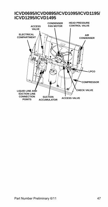
ICVD0695/ICVD0895/ICVD1095/ICVD1195/ICVD1295/ICVD1495
ACCESS VALVE
CONDENSER FAN MOTOR
HEAD PRESSURECONTROL VALVE
AIR CONDENSER
COMPRESSOR
SUCTIONACCUMULATOR
LIQUID LINE ANDSUCTION LINECONNECTION
POINTS
ELECTRICAL COMPARTMENT
CHECK VALVE
ACCESS VALVE
LPCO
48 Part Number Preliminary 6/11
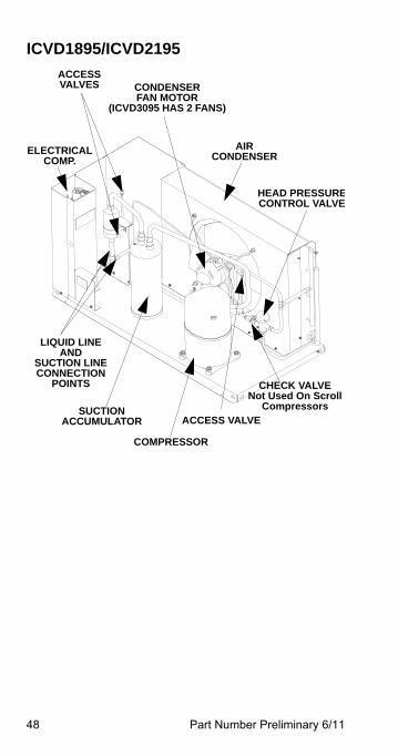
ICVD1895/ICVD2195
SUCTIONACCUMULATOR
COMPRESSOR
LIQUID LINEAND
SUCTION LINECONNECTION
POINTS
AIRCONDENSER
HEAD PRESSURECONTROL VALVE
CONDENSERFAN MOTOR
(ICVD3095 HAS 2 FANS)
ACCESSVALVES
ELECTRICALCOMP.
CHECK VALVENot Used On Scroll
CompressorsACCESS VALVE
Part Number Preliminary 6/11 49
Maintenance
Cleaning and Sanitizing
GENERALYou are responsible for maintaining the ice machine in accordance with the instructions in this manual. Maintenance procedures are not covered by the warranty.
Clean and sanitize the ice machine every six months for efficient operation. If the ice machine requires more frequent cleaning and sanitizing, consult a qualified service company to test the water quality and recommend appropriate water treatment. An extremely dirty ice machine must be taken apart for cleaning and sanitizing.
Manitowoc Ice Machine Cleaner and Sanitizer are the only products approved for use in Manitowoc ice machines.
50 Part Number Preliminary 6/11
! CautionUse only Manitowoc approved Ice MachineCleaner and Sanitizer for this application(Manitowoc Cleaner part number 94-0546-3 andManitowoc Sanitizer part number 94-0565-3). It isa violation of Federal law to use these solutions ina manner inconsistent with their labeling. Readand understand all labels printed on bottles beforeuse.
! CautionDo not mix Cleaner and Sanitizer solutionstogether. It is a violation of Federal law to usethese solutions in a manner inconsistent with theirlabeling.
! WarningWear rubber gloves and safety goggles (and/orface shield) when handling Ice Machine Cleaneror Sanitizer.
Part Number Preliminary 6/11 51
CLEANING/SANITIZING PROCEDUREThis procedure must be performed a minimum of once every six months.
• The ice machine and bin must be disassembled cleaned and sanitized.
• All ice produced during the cleaning and sanitizing procedures must be discarded.
• Removes mineral deposits from areas or surfaces that are in direct contact with water.
PREVENTATIVE MAINTENANCE CLEANING PROCEDURE• This procedure cleans all components in the water
flow path, and is used to clean the ice machine between the bi-yearly cleaning/sanitizing procedure.
EXTERIOR CLEANINGClean the area around the ice machine as often as necessary to maintain cleanliness and efficient operation.
Wipe surfaces with a damp cloth rinsed in water to remove dust and dirt from the outside of the ice machine. If a greasy residue persists, use a damp cloth rinsed in a mild dish soap and water solution. Wipe dry with a clean, soft cloth.
The exterior panels have a clear coating that is stain resistant and easy to clean. Products containing abrasives will damage the coating and scratch the panels.
• Never use steel wool or abrasive pads for cleaning.
• Never use chlorinated, citrus based or abrasive cleaners on exterior panels and plastic trim pieces.
52 Part Number Preliminary 6/11
Cleaning / Sanitizing Procedure
CLEANING PROCEDURE
Ice machine cleaner is used to remove lime scale and mineral deposits. Ice machine sanitizer disinfects and removes algae and slime.
NOTE: Although not required and dependant on your installation, removing the ice machine top cover may allow easier access.
! CautionUse only Manitowoc approved Ice MachineCleaner and Sanitizer for this application(Manitowoc Cleaner part number 94-0546-3 andManitowoc Sanitizer part number 94-0565-3). It isa violation of Federal law to use these solutions ina manner inconsistent with their labeling. Readand understand all labels printed on bottles beforeuse.
! CautionDo not mix Cleaner and Sanitizer solutionstogether. It is a violation of Federal law to usethese solutions in a manner inconsistent with theirlabeling.
! WarningWear rubber gloves and safety goggles (and/orface shield) when handling Ice Machine Cleaneror Sanitizer.
Part Number Preliminary 6/11 53
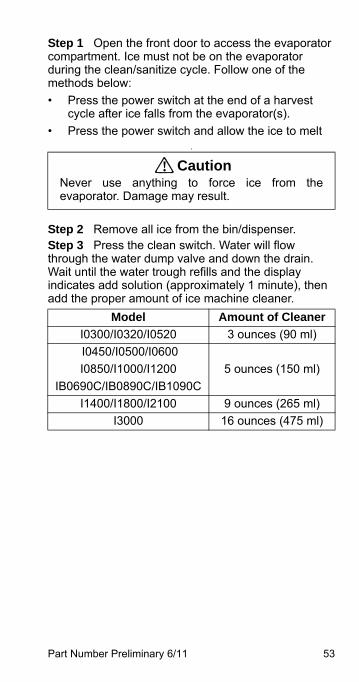
Step 1 Open the front door to access the evaporator compartment. Ice must not be on the evaporator during the clean/sanitize cycle. Follow one of the methods below:
• Press the power switch at the end of a harvest cycle after ice falls from the evaporator(s).
• Press the power switch and allow the ice to melt.
Step 2 Remove all ice from the bin/dispenser.Step 3 Press the clean switch. Water will flow through the water dump valve and down the drain. Wait until the water trough refills and the display indicates add solution (approximately 1 minute), then add the proper amount of ice machine cleaner.
! CautionNever use anything to force ice from theevaporator. Damage may result.
Model Amount of Cleaner
I0300/I0320/I0520 3 ounces (90 ml)
I0450/I0500/I0600
I0850/I1000/I1200
IB0690C/IB0890C/IB1090C
5 ounces (150 ml)
I1400/I1800/I2100 9 ounces (265 ml)
I3000 16 ounces (475 ml)
54 Part Number Preliminary 6/11
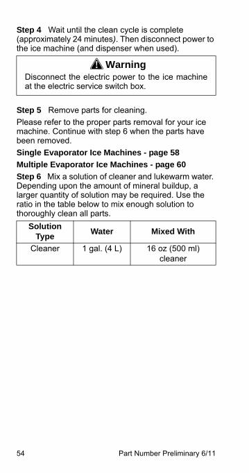
Step 4 Wait until the clean cycle is complete (approximately 24 minutes). Then disconnect power to the ice machine (and dispenser when used).
Step 5 Remove parts for cleaning.
Please refer to the proper parts removal for your ice machine. Continue with step 6 when the parts have been removed.
Single Evaporator Ice Machines - page 58
Multiple Evaporator Ice Machines - page 60
Step 6 Mix a solution of cleaner and lukewarm water. Depending upon the amount of mineral buildup, a larger quantity of solution may be required. Use the ratio in the table below to mix enough solution to thoroughly clean all parts.
! WarningDisconnect the electric power to the ice machineat the electric service switch box.
Solution Type
Water Mixed With
Cleaner 1 gal. (4 L) 16 oz (500 ml) cleaner
Part Number Preliminary 6/11 55
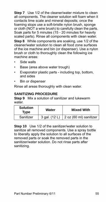
Step 7 Use 1/2 of the cleaner/water mixture to clean all components. The cleaner solution will foam when it contacts lime scale and mineral deposits; once the foaming stops use a soft-bristle nylon brush, sponge or cloth (NOT a wire brush) to carefully clean the parts. Soak parts for 5 minutes (15 - 20 minutes for heavily scaled parts). Rinse all components with clean water.Step 8 While components are soaking, use 1/2 of the cleaner/water solution to clean all food zone surfaces of the ice machine and bin (or dispenser). Use a nylon brush or cloth to thoroughly clean the following ice machine areas:
• Side walls
• Base (area above water trough)
• Evaporator plastic parts - including top, bottom, and sides
• Bin or dispenser
Rinse all areas thoroughly with clean water.
SANITIZING PROCEDUREStep 9 Mix a solution of sanitizer and lukewarm water.
Step 10 Use 1/2 of the sanitizer/water solution to sanitize all removed components. Use a spray bottle to liberally apply the solution to all surfaces of the removed parts or soak the removed parts in the sanitizer/water solution. Do not rinse parts after sanitizing.
Solution Type
Water Mixed With
Sanitizer 3 gal. (12 L) 2 oz (60 ml) sanitizer
56 Part Number Preliminary 6/11
Step 11 Use 1/2 of the sanitizer/water solution to sanitize all food zone surfaces of the ice machine and bin (or dispenser). Use a spray bottle to liberally apply the solution. When sanitizing, pay particular attention to the following areas:
• Side walls
• Base (area above water trough)
• Evaporator plastic parts - including top, bottom and sides
• Bin or dispenser
Do not rinse the sanitized areas.
Step 12 Replace all removed components.Step 13 Wait 20 minutes.Step 14 Reapply power to the ice machine and press the Clean button.

Part Number Preliminary 6/11 57
Step 15 Wait until the water trough refills and the display indicates add solution (approximately 1 minute). Add the proper amount of Manitowoc Ice Machine Sanitizer to the water trough by pouring between the water curtain and evaporator.
Step 16 Select auto ice on, press the checkmark and close and secure the front door. The ice machine will automatically start ice making after the sanitize cycle is complete (approximately 24 minutes).
Model Amount of Sanitizer
I0300/I0320/I0520 3 ounces (90 ml)
I0450/I0500/I0600
I0850/I1000/I1200
IB0690C/IB0890C
3 ounces (90 ml)
IB1090C 3.5 ounces (104 ml)
I1400/I1800/I2100 12 ounces (355 ml)
I3300 25 ounces (740 ml)
58 Part Number Preliminary 6/11
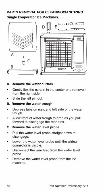
PARTS REMOVAL FOR CLEANING/SANITIZING
Single Evaporator Ice Machines.
A. Remove the water curtain
• Gently flex the curtain in the center and remove it from the right side.
• Slide the left pin out.
B. Remove the water trough
• Depress tabs on right and left side of the water trough.
• Allow front of water trough to drop as you pull forward to disengage the rear pins.
C. Remove the water level probe
• Pull the water level probe straight down to disengage.
• Lower the water level probe until the wiring connector is visible.
• Disconnect the wire lead from the water level probe.
• Remove the water level probe from the ice machine.
B
C
D E
A
OffOn / Off Mode
[ ]!
Part Number Preliminary 6/11 59
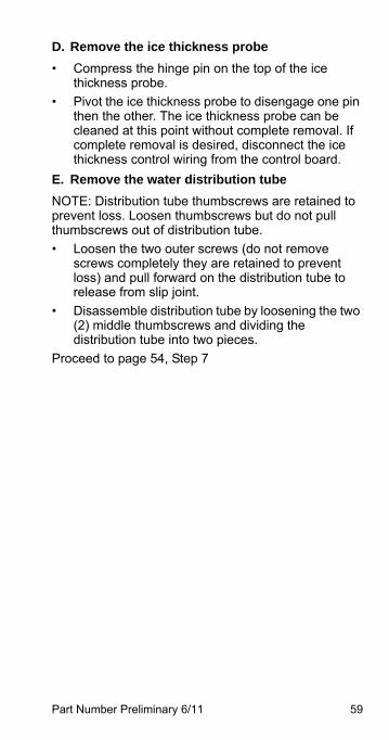
D. Remove the ice thickness probe
• Compress the hinge pin on the top of the ice thickness probe.
• Pivot the ice thickness probe to disengage one pin then the other. The ice thickness probe can be cleaned at this point without complete removal. If complete removal is desired, disconnect the ice thickness control wiring from the control board.
E. Remove the water distribution tube
NOTE: Distribution tube thumbscrews are retained to prevent loss. Loosen thumbscrews but do not pull thumbscrews out of distribution tube.
• Loosen the two outer screws (do not remove screws completely they are retained to prevent loss) and pull forward on the distribution tube to release from slip joint.
• Disassemble distribution tube by loosening the two (2) middle thumbscrews and dividing the distribution tube into two pieces.
Proceed to page 54, Step 7
60 Part Number Preliminary 6/11
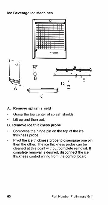
Ice Beverage Ice Machines
A. Remove splash shield
• Grasp the top center of splash shields.
• Lift up and then out.
B. Remove ice thickness probe
• Compress the hinge pin on the top of the ice thickness probe.
• Pivot the ice thickness probe to disengage one pin then the other. The ice thickness probe can be cleaned at this point without complete removal. If complete removal is desired, disconnect the ice thickness control wiring from the control board.
A
B
C
DE
Part Number Preliminary 6/11 61
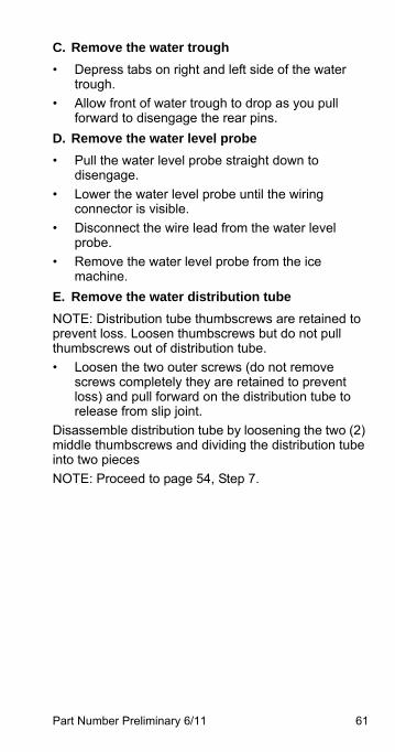
C. Remove the water trough
• Depress tabs on right and left side of the water trough.
• Allow front of water trough to drop as you pull forward to disengage the rear pins.
D. Remove the water level probe
• Pull the water level probe straight down to disengage.
• Lower the water level probe until the wiring connector is visible.
• Disconnect the wire lead from the water level probe.
• Remove the water level probe from the ice machine.
E. Remove the water distribution tube
NOTE: Distribution tube thumbscrews are retained to prevent loss. Loosen thumbscrews but do not pull thumbscrews out of distribution tube.
• Loosen the two outer screws (do not remove screws completely they are retained to prevent loss) and pull forward on the distribution tube to release from slip joint.
Disassemble distribution tube by loosening the two (2) middle thumbscrews and dividing the distribution tube into two pieces
NOTE: Proceed to page 54, Step 7.
62 Part Number Preliminary 6/11
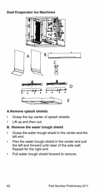
Dual Evaporator Ice Machines
A.Remove splash shields
• Grasp the top center of splash shields.
• Lift up and then out.
B. Remove the water trough shield
• Grasp the water trough shield in the center and the left end.
• Flex the water trough shield in the center and pull the left end forward until clear of the side wall. Repeat for the right end.
• Pull water trough shield forward to remove.
A B
C
D
E
Part Number Preliminary 6/11 63
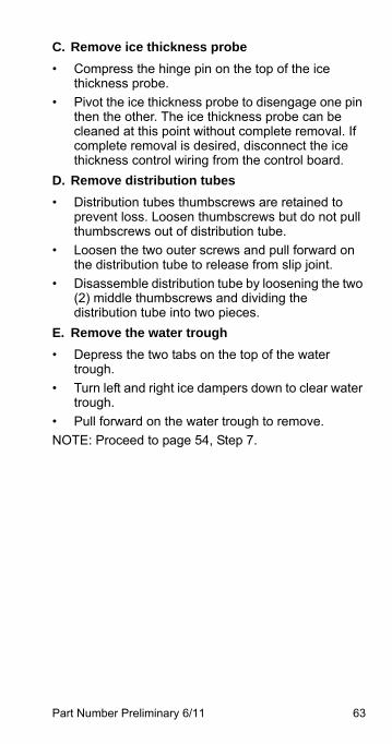
C. Remove ice thickness probe
• Compress the hinge pin on the top of the ice thickness probe.
• Pivot the ice thickness probe to disengage one pin then the other. The ice thickness probe can be cleaned at this point without complete removal. If complete removal is desired, disconnect the ice thickness control wiring from the control board.
D. Remove distribution tubes
• Distribution tubes thumbscrews are retained to prevent loss. Loosen thumbscrews but do not pull thumbscrews out of distribution tube.
• Loosen the two outer screws and pull forward on the distribution tube to release from slip joint.
• Disassemble distribution tube by loosening the two (2) middle thumbscrews and dividing the distribution tube into two pieces.
E. Remove the water trough
• Depress the two tabs on the top of the water trough.
• Turn left and right ice dampers down to clear water trough.
• Pull forward on the water trough to remove.
NOTE: Proceed to page 54, Step 7.
64 Part Number Preliminary 6/11
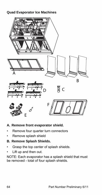
Quad Evaporator Ice Machines
A. Remove front evaporator shield.
• Remove four quarter turn connectors
• Remove splash shield
B. Remove Splash Shields.
• Grasp the top center of splash shields.
• Lift up and then out.
NOTE: Each evaporator has a splash shield that must be removed - total of four splash shields.
E
D C
A
B
F
Part Number Preliminary 6/11 65
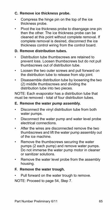
C. Remove ice thickness probe.
• Compress the hinge pin on the top of the ice thickness probe.
• Pivot the ice thickness probe to disengage one pin then the other. The ice thickness probe can be cleaned at this point without complete removal. If complete removal is desired, disconnect the ice thickness control wiring from the control board.
D. Remove distribution tubes.
• Distribution tube thumbscrews are retained to prevent loss. Loosen thumbscrews but do not pull thumbscrews out of distribution tube.
• Loosen the two outer screws and pull forward on the distribution tube to release from slip joint.
• Disassemble distribution tube by loosening the two (2) middle thumbscrews and dividing the distribution tube into two pieces.
NOTE: Each evaporator has a distribution tube that must be removed - total of four distribution tubes.
E. Remove the water pump assembly.
• Disconnect the vinyl distribution tube from both water pumps.
• Disconnect the water pump and water level probe electrical connections.
• After the wires are disconnected remove the two thumbscrews and lift the water pump assembly out of the ice machine.
• Remove the thumbscrews securing the water pumps (2 each pump) and remove water pumps. Do not immerse the water pump motor in cleaner or sanitizer solutions.
• Remove the water level probe from the assembly housing.
F. Remove the water trough.
• Pull forward on the water trough to remove.
NOTE: Proceed to page 54, Step 7.
66 Part Number Preliminary 6/11
Ice Thickness Probe & Water Level Probe
Clean the probes using the following procedure.
1. Mix a solution of Manitowoc ice machine cleaner and water (2 ounces of cleaner to 16 ounces of water) in a container.
2. Soak probes in container of cleaner/water solution while disassembling and cleaning water circuit components (soak probes for 10 minutes or longer).
3. Clean all probe surfaces including all plastic parts (do not use abrasives). Verify all cavities are clean. Thoroughly rinse probes (including cavity) with clean water, then dry completely. Incomplete rinsing and drying of the ice thickness probe can cause premature harvest.
4. Reinstall probes, then sanitize the ice machine and bin/dispenser interior surfaces.
Part Number Preliminary 6/11 67
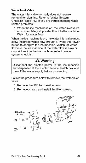
Water Inlet Valve
The water inlet valve normally does not require removal for cleaning. Refer to “Water System Checklist” page 163, if you are troubleshooting water related problems.
1. When the ice machine is off, the water inlet valve must completely stop water flow into the machine. Watch for water flow.
When the ice machine is on, the water inlet valve must allow the proper water flow through it. Press the Power button to energize the ice machine. Watch for water flow into the ice machine. If the water flow is slow or only trickles into the ice machine, refer to water system checklist.
Follow the procedure below to remove the water inlet valve.
1. Remove the 1/4” hex head screws.
2. Remove, clean, and install the filter screen.
! WarningDisconnect the electric power to the ice machineand dispenser at the electric service switch box andturn off the water supply before proceeding.
4 Hex Head Screws
68 Part Number Preliminary 6/11
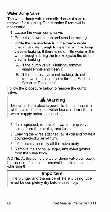
Water Dump Valve
The water dump valve normally does not require removal for cleaning. To determine if removal is necessary:
1. Locate the water dump valve.
2. Press the power button and stop ice making.
3. While the ice machine is in the freeze mode, check the water trough to determine if the dump valve is leaking. If there is no or little water in the water trough (during the freeze cycle) the dump valve is leaking.
A. If the dump valve is leaking, remove, disassemble and clean it.
B. If the dump valve is not leaking, do not remove it. Instead, follow the “Ice Machine Cleaning Procedure”.
Follow the procedure below to remove the dump valve.
4. If so equipped, remove the water dump valve shield from its mounting bracket.
5. Leaving the wires attached, twist coil and rotate it counter-clockwise1/4 turn.
6. Lift the coil assembly off the valve body.
7. Remove the spring, plunger, and nylon gasket from the valve body.
NOTE: At this point, the water dump valve can easily be cleaned. If complete removal is desired, continue with step 5.
! WarningDisconnect the electric power to the ice machineat the electric service switch box and turn off thewater supply before proceeding.
ImportantThe plunger and the inside of the enclosing tubemust be completely dry before assembly.
Part Number Preliminary 6/11 69
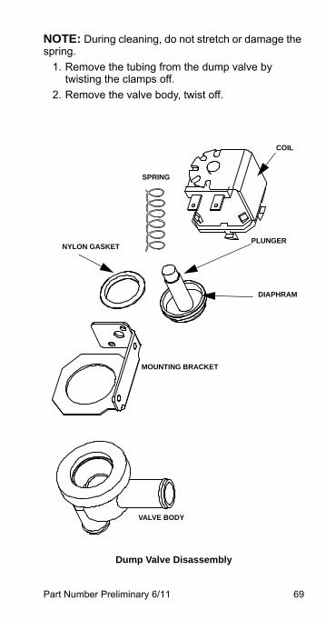
NOTE: During cleaning, do not stretch or damage the spring.
1. Remove the tubing from the dump valve by twisting the clamps off.
2. Remove the valve body, twist off.
Dump Valve Disassembly
SPRING
PLUNGER
DIAPHRAM
VALVE BODY
COIL
MOUNTING BRACKET
NYLON GASKET
70 Part Number Preliminary 6/11
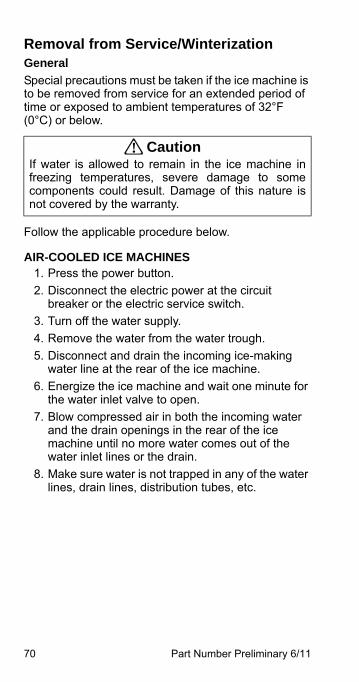
Removal from Service/WinterizationGeneral
Special precautions must be taken if the ice machine is to be removed from service for an extended period of time or exposed to ambient temperatures of 32°F (0°C) or below.
Follow the applicable procedure below.
AIR-COOLED ICE MACHINES1. Press the power button.
2. Disconnect the electric power at the circuit breaker or the electric service switch.
3. Turn off the water supply.
4. Remove the water from the water trough.
5. Disconnect and drain the incoming ice-making water line at the rear of the ice machine.
6. Energize the ice machine and wait one minute for the water inlet valve to open.
7. Blow compressed air in both the incoming water and the drain openings in the rear of the ice machine until no more water comes out of the water inlet lines or the drain.
8. Make sure water is not trapped in any of the water lines, drain lines, distribution tubes, etc.
! CautionIf water is allowed to remain in the ice machine infreezing temperatures, severe damage to somecomponents could result. Damage of this nature isnot covered by the warranty.
Part Number Preliminary 6/11 71
WATER-COOLED ICE MACHINES1. Perform steps 1-6 under “Self-Contained Air-
Cooled Ice Machines.”
2. Disconnect the incoming water and drain line from the water-cooled condenser.
3. Energize the ice machine in the freeze cycle. The increasing refrigerant pressure will open the water regulating valve.
4. Blow compressed air through the condenser until no water remains.

72 Part Number Preliminary 6/11
This Page Intentionally Left Blank
Part Number Preliminary 6/11 73
Operation
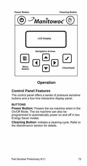
Control Panel FeaturesThe control panel offers a series of pressure sensitive buttons and a four-line interactive display panel.
BUTTONSPower Button: Powers the ice machine when in the On/Off Mode. The ice machine can also be programmed to automatically power on and off in two Energy Saver modes.
Cleaning Button: Initiates a cleaning cycle. Refer to the Maintenance section for details.
Manitowoc
Menu Button
Power Button
LCD Display
Checkmark
Cleaning Button
Navigation Arrows
74 Part Number Preliminary 6/11
Menu Button: Moves the display from the Home Screen, where ice machine status, alerts and messages are viewed, to the Main Menu, where machine information and its event log can be accessed, machine and Energy Saver settings can be adjusted, and service issues can be addressed.
Left and Right Arrows: The Left arrow moves the display to the previous screen, allowing the user to “back out” of programming. Both the Left and Right arrows will move the cursor (underline) within a line of settings. NOTE: The Right arrow can also be used on many screens interchangeably with the checkmark to make a selection.
Up and Down Arrows: Move the highlight [brackets] up one line or down one line.
Checkmark: Makes a selection and/or moves to the next screen (or line).
DISPLAY PANELThe LCD display panel is 16 characters wide and four lines deep. During ice machine operation and cleaning cycles, the Home screen’s top three lines provide valuable status information and the fourth line shows alerts and messages. In programming, four lines of the current screen are displayed and highlights, arrows, cursor and selections inform the user of available actions.
Part Number Preliminary 6/11 75
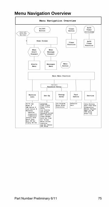
Menu Navigation Overview
On/OffButton
Menu Navigation Overview
Home Screen
When Alert Present
When Message Present
Alerts Menu
Messages Menu
Press Left Arrow From Main Menu
Clean Button
AuCSTimer
Initiated
Clean Function
AuCSClean
Function
MenuButton
Main Menu Function
MachineInfo
Set-UpFactDeflts
Energy Saver
Service
Time & DateTime Config
Edit Password
UnitsIce ClarityLCD BrightPassword On/Off
Clean MinderAuCS Run TimeAir FilterWater FilterLuminIce
Ice ProgramWater MiserStatistics
(Optional) Password Entry
90/70 capModel #IMH Serial #Cond Serial #Warranty -Machine -Evaporator -CompressorInstall DateManuf DateMain SW VerDisply SW Ver
Language
USB SetupIce Bin Sensor
DefaultsExit Real Time Data
DiagnosticsManual HarvestRepl Cnt BdUSB SetupEvent Log
Data History
76 Part Number Preliminary 6/11
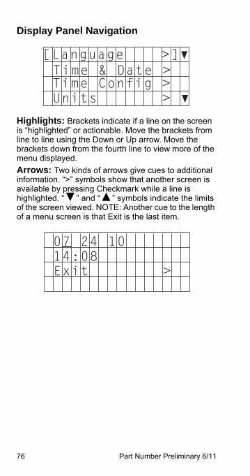
Display Panel Navigation
Highlights: Brackets indicate if a line on the screen is “highlighted” or actionable. Move the brackets from line to line using the Down or Up arrow. Move the brackets down from the fourth line to view more of the menu displayed.
Arrows: Two kinds of arrows give cues to additional information. “>” symbols show that another screen is available by pressing Checkmark while a line is highlighted. “▼” and “▲” symbols indicate the limits of the screen viewed. NOTE: Another cue to the length of a menu screen is that Exit is the last item.
Time & Date >Time Config >Units > ▼
[Language >]▼
07 24 1014:08Exit >
Part Number Preliminary 6/11 77
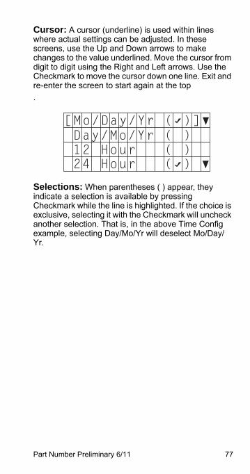
Cursor: A cursor (underline) is used within lines where actual settings can be adjusted. In these screens, use the Up and Down arrows to make changes to the value underlined. Move the cursor from digit to digit using the Right and Left arrows. Use the Checkmark to move the cursor down one line. Exit and re-enter the screen to start again at the top
.
Selections: When parentheses ( ) appear, they indicate a selection is available by pressing Checkmark while the line is highlighted. If the choice is exclusive, selecting it with the Checkmark will uncheck another selection. That is, in the above Time Config example, selecting Day/Mo/Yr will deselect Mo/Day/Yr.
[Mo/Day/Yr ( )]▼Day/Mo/Yr ( )12 Hour ( )24 Hour ( ) ▼
78 Part Number Preliminary 6/11
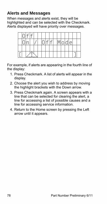
Alerts and MessagesWhen messages and alerts exist, they will be highlighted and can be selected with the Checkmark. Alerts displayed will have priority over messages.
For example, if alerts are appearing in the fourth line of the display:
1. Press Checkmark. A list of alerts will appear in the display.
2. Choose the alert you wish to address by moving the highlight brackets with the Down arrow.
3. Press Checkmark again. A screen appears with a line that can be selected for clearing the alert, a line for accessing a list of possible causes and a line for accessing service information.
4. Return to the Home screen by pressing the Left arrow until it appears.
OffOn / Off Mode
[ ]!
Part Number Preliminary 6/11 79
Main Menu
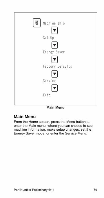
Main MenuFrom the Home screen, press the Menu button to enter the Main menu, where you can choose to see machine information, make setup changes, set the Energy Saver mode, or enter the Service Menu.
Machine Info
Set-Up
Energy Saver
Factory Defaults
Service
Exit
80 Part Number Preliminary 6/11
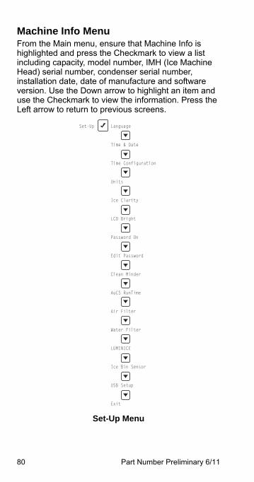
Machine Info MenuFrom the Main menu, ensure that Machine Info is highlighted and press the Checkmark to view a list including capacity, model number, IMH (Ice Machine Head) serial number, condenser serial number, installation date, date of manufacture and software version. Use the Down arrow to highlight an item and use the Checkmark to view the information. Press the Left arrow to return to previous screens.
Set-Up Menu
Set-Up Language
Time & Date
Time Configuration
Units
Ice Clarity
LCD Bright
Password On
Edit Password
Clean Minder
AuCS RunTime
Air Filter
Water Filter
LUMINICE
Ice Bin Sensor
USB Setup
Exit
Part Number Preliminary 6/11 81
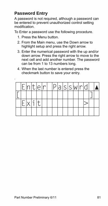
Password Entry A password is not required, although a password can be entered to prevent unauthorized control setting modification.
To Enter a password use the following procedure.
1. Press the Menu button.
2. From the Main menu, use the Down arrow to highlight setup and press the right arrow.
3. Enter the numerical password with the up and/or down arrow. Press the right arrow to move to the next cell and add another number. The password can be from 1 to 13 numbers long.
4. When the last number is entered press the checkmark button to save your entry.
.
[ ]Exit >
Enter Passwrd ▲
82 Part Number Preliminary 6/11
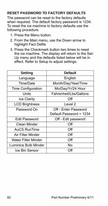
RESET PASSWORD TO FACTORY DEFAULTSThe password can be reset to the factory defaults when required. The default factory password is 1234. To reset the ice machine to factory defaults use the following procedure.
1. Press the Menu button.
2. From the Main menu, use the Down arrow to highlight Fact Deflts
3. Press the Checkmark button two times to reset the ice machine. The display will return to the Set-Up menu and the defaults listed below will be in effect. Refer to Setup to adjust settings.
Setting Default
Language English
Time/Date Month/Day/Year/Time
Time Configuration Mo/Day/Yr/24 Hour
Units Fahrenheit/Lbs/Gallons
Ice Clarity Off
LCD Brightness Level 2
Password On Off - Enter PasswordDefault Password = 1234
Edit Password Off - Edit password
Clean Minder Off
AuCS RunTime Off
Air Filter Minder Off
Water Filter Minder Off
LuminIce Bulb Minder No
Ice Bin Sensor Off
Part Number Preliminary 6/11 83
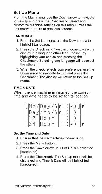
Set-Up MenuFrom the Main menu, use the Down arrow to navigate to Set-Up and press the Checkmark. Select and customize machine settings on this menu. Press the Left arrow to return to previous screens.
LANGUAGE1. From the Set-Up menu, use the Down arrow to
highlight Language.
2. Press the Checkmark. You can choose to view the display in a language other than English, by highlighting your choice and pressing the Checkmark. Selecting one language will deselect the others.
3. When the check reflects your preference, use the Down arrow to navigate to Exit and press the Checkmark. The display will return to the Set-Up menu.
TIME & DATEWhen the ice machine is installed, the correct time and date needs to be set for its location.
Set the Time and Date
1. Ensure that the ice machine’s power is on.
2. Press the Menu button.
3. Press the Down arrow until Set-Up is highlighted [bracketed].
4. Press the Checkmark. The Set-Up menu will be displayed and Time & Date will be highlighted [bracketed].
[Mo/Day/Yr ( )]▼Day/Mo/Yr ( )12 Hour ( )24 Hour ( ) ▼
84 Part Number Preliminary 6/11
5. Press the Checkmark. The date will appear on the first line of the display (Mo/Day/Yr) and the time will appear on the second line (24 Hour). The month will be underlined.
6. Using the Up or Down arrow, adjust the month, if necessary.
7. When the correct month appears, use the Right arrow to move the underline to the day.
8. Using the Up or Down arrow, adjust the day, if necessary.
9. When the correct day appears, use the Right arrow to move the underline to the year.
10. Using the Up or Down arrow, adjust the year, if necessary.
11. When the correct year appears, press the Checkmark. The underline will move down to the hour.
12. Using the Up or Down arrow, adjust the hour, if necessary.
13. When the correct hour appears, use the Right arrow to move the underline to minutes.
14. Using the Up or Down arrow, adjust the minutes, if necessary.
15. When the correct minutes appear, press the Checkmark twice.
Part Number Preliminary 6/11 85
TIME CONFIGURATION1. From the Set-Up menu, use the Down arrow to
highlight Time Config.
2. Press the Checkmark. On this screen, you can choose whether the date will be displayed as Mo/Day/Yr or Day/Mo/Yr by highlighting your choice and pressing the Checkmark. Selecting one will deselect the other.
3. You can also choose whether the time will be displayed as 12 Hour or 24 Hour by highlighting your choice and pressing the Checkmark. Selecting one will deselect the other.
4. When the two checks reflect your preference, use the Down arrow to navigate to Exit and press the Checkmark. The display will return to the Set-Up menu.
UNITS1. From the Set-Up menu, use the Down arrow to
highlight Units.
2. Press the Checkmark. On this screen, you can choose whether the ice machine will display measurements in Celsius or Fahrenheit, kilograms or pounds, and gallons or liters by highlighting your choice of each pair and pressing the Checkmark. Selecting one of each pair will deselect the other. Make sure to navigate with the Down arrow to make all three choices.
3. When the three checks reflect your preferences, use the Down arrow to navigate to Exit and press the Checkmark. The display will return to the Set-Up menu.
86 Part Number Preliminary 6/11
ICE CLARITYIn areas with poor potable water quality, the ice machine makes cloudy ice. Setting Ice Clarity to ON will add additional water during the freeze cycle to dilute the water that contains a high content of dissolved solids in the water trough. This feature decreases production and increases water usage. A water filter is recommended to produce the highest quality ice while maintaining the least expensive mode of operation.
1. From the Set-Up menu, use the Down arrow to highlight Ice Clarity.
2. Press the Checkmark. On this screen, you can choose to turn the ice clarity feature ON or OFF by highlighting your choice and pressing the Checkmark. Selecting one will deselect the other.
3. When the check reflects your preference, use the Down arrow to navigate to Exit and press the Checkmark. The display will return to the Set-Up menu.
LCD BRIGHTNESSHere, the brightness of the LCD display can be adjusted.
1. From the Set-Up menu, use the Down arrow to highlight LCD Bright.
2. Press the Checkmark. You will see one of four checkmarks indicating the brightness levels of the display. Level 1 is one checkmark, level 2 is two checkmarks, Level 3 is three checkmarks, etc.
3. Use the Up and Down arrows to select your preference.
4. When the checkmarks reflect your preference, press the Checkmark. The display will return to the Set-Up menu.
Part Number Preliminary 6/11 87
PASSWORD ONA password can be added to prevent unauthorized changes to ice machine settings.
1. From the Set-Up menu, use the Down arrow to highlight Password On.
2. Enter the password and press the Checkmark.
3. Press the Left arrow to return to previous screens and to the Set-Up menu.
EDIT PASSWORDThe password can be changed on this screen
1. From the Set-Up menu, use the Down arrow to highlight Edit Password.
2. Press the Checkmark and confirm current password.
3. Enter new password and press the Checkmark.
4. Press the Left arrow to return to previous screens and to the Set-Up menu.
CLEAN MINDERClean Minder is a feature that displays a cleaning reminder at a set time interval.
1. From the Set-Up menu, use the Down arrow to highlight Clean Minder.
2. Press the Checkmark. On this screen, you can choose to turn the reminder ON or OFF by highlighting your choice and pressing the Checkmark. Selecting one will deselect the other.
3. You can also choose the time interval from this screen by highlighting Set Interval and pressing the Checkmark.
4. Press the Left arrow to return to previous screens and to the Set-Up menu.
88 Part Number Preliminary 6/11
IAUCS RUNTIMEAutomatic Cleaning System is an optional accessory and will perform a cleaning cycle at a set time interval.
1. From the Set-Up menu, use the Down arrow to highlight AuCS RunTime.
2. Press the Checkmark. On this screen, you can choose to turn the feature ON or OFF by highlighting your choice and pressing the Checkmark. Selecting one will deselect the other.
3. You can also choose the time interval from this screen by highlighting Set Interval and pressing the Checkmark.
4. Press the Left arrow to return to previous screens and to the Set-Up menu.
AIR FILTERThe ice machine has a feature that displays a clean air filter reminder at a set time interval.
1. From the Set-Up menu, use the Down arrow to highlight Air Filter.
2. Press the Checkmark. On this screen, you can choose to turn the reminder to AUTO or OFF by highlighting your choice and pressing the Checkmark. Selecting one will deselect the other.
3. You can also choose the time interval from this screen by highlighting Set Interval and pressing the Checkmark.
4. Press the Left arrow to return to previous screens and to the Set-Up menu.
Part Number Preliminary 6/11 89
WATER FILTERThe ice machine has a feature that displays a replace water filter reminder at a set time interval.
1. From the Set-Up menu, use the Down arrow to highlight Water Filter.
2. Press the Checkmark. You can record the filter type on this screen by highlighting Filter Type and pressing the Checkmark.
3. After making your selection, press the Left arrow to return to the previous screen.
4. On this screen, you can also choose to turn the reminder to AUTO or OFF by highlighting your choice and pressing the Checkmark. Selecting one will deselect the other.
5. You can further choose the time interval from this screen by highlighting Set Interval and pressing the Checkmark.
6. Press the Left arrow to return to previous screens and to the Set-Up menu.
LUMINICE™ REMINDERThe LuminIce™ growth inhibitor recirculates the air in the ice machine foodzone over a UV bulb. This process will inhibit the growth of common micro-organisms on all exposed foodzone surfaces.
The Ionic Minder is a feature that displays a reminder to change its bulb every 12 months.
1. From the Set-Up menu, use the Down arrow to highlight Ionic Minder.
2. Press the Checkmark. On this screen, you can choose to turn the reminder to AUTO or OFF by highlighting your choice and pressing the Checkmark. Selecting one will deselect the other.
3. When the check reflects your preference, use the Down arrow to navigate to Exit and press the Checkmark. The display will return to the Set-Up menu.
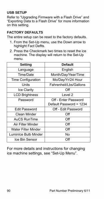
90 Part Number Preliminary 6/11
USB SETUPRefer to “Upgrading Firmware with a Flash Drive” and “Exporting Data to a Flash Drive” for more information on this setting.
FACTORY DEFAULTSThe entire setup can be reset to the factory defaults.
1. From the Set-Up menu, use the Down arrow to highlight Fact Deflts.
2. Press the Checkmark two times to reset the ice machine. The display will return to the Set-Up menu.
For more details and instructions for changing ice machine settings, see “Set-Up Menu”.
Setting Default
Language English
Time/Date Month/Day/Year/Time
Time Configuration Mo/Day/Yr/24 Hour
Units Fahrenheit/Lbs/Gallons
Ice Clarity Off
LCD Brightness Level 2
Password Off - Enter Password Default Password = 1234
Edit Password Off - Edit Password
Clean Minder Off
AuCS RunTime Off
Air Filter Minder Off
Water Filter Minder Off
LuminIce Bulb Minder No
Ice Bin Sensor Off
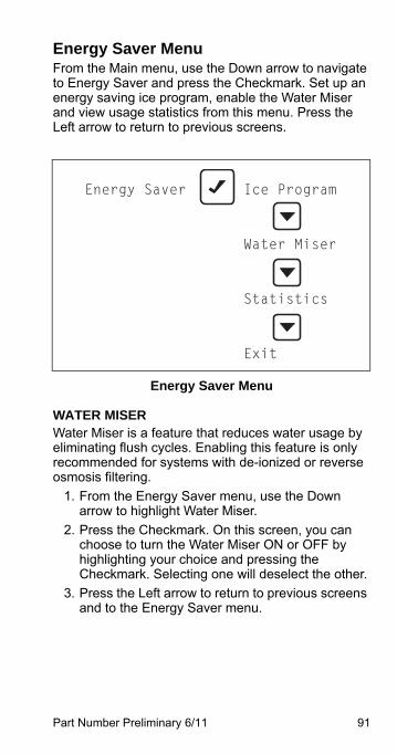
Part Number Preliminary 6/11 91
Energy Saver MenuFrom the Main menu, use the Down arrow to navigate to Energy Saver and press the Checkmark. Set up an energy saving ice program, enable the Water Miser and view usage statistics from this menu. Press the Left arrow to return to previous screens.
Energy Saver Menu
WATER MISERWater Miser is a feature that reduces water usage by eliminating flush cycles. Enabling this feature is only recommended for systems with de-ionized or reverse osmosis filtering.
1. From the Energy Saver menu, use the Down arrow to highlight Water Miser.
2. Press the Checkmark. On this screen, you can choose to turn the Water Miser ON or OFF by highlighting your choice and pressing the Checkmark. Selecting one will deselect the other.
3. Press the Left arrow to return to previous screens and to the Energy Saver menu.
Energy Saver Ice Program
Water Miser
Statistics
Exit
92 Part Number Preliminary 6/11
ICE PROGRAMTo save energy and water, the ice machine can be programmed to only power up during time periods that the ice will be used or when the bin level is being depleted by heavy use.
1. In the Energy Saver menu, ensure that Ice Program is highlighted.
2. Press the Checkmark. On this screen, you can choose to turn on the time program or the bin level program by highlighting your choice and pressing the Checkmark. Selecting one will deselect the other. If one of them is selected and you wish to turn both off, highlight the choice and press Checkmark again.
3. If neither of the programs is selected, highlighting Next and pressing the Checkmark will simply return to the top of this screen. If one of the programs is selected, highlight Next and press the Checkmark to choose the times or bin levels. NOTE: For details on how to use the cursor for the time program, refer to “Display Panel Navigation” in this section.
4. Select Exit to return to previous screens and again to the Energy Saver menu.
STATISTICS1. From the Energy Saver menu, use the Down
arrow to highlight Statistics.
2. Press the Checkmark. Choose to view ice production, potable water usage or energy usage statistics by highlighting your choice and pressing the Checkmark.
3. Press the Left arrow to return to previous screens and to the Energy Saver menu.
ImportantSetting an ice program will take the ice machineout of the On/Off Mode and the Power button willbe disabled.
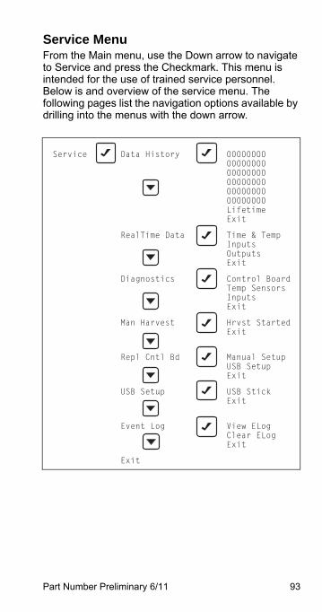
Part Number Preliminary 6/11 93
Service MenuFrom the Main menu, use the Down arrow to navigate to Service and press the Checkmark. This menu is intended for the use of trained service personnel. Below is and overview of the service menu. The following pages list the navigation options available by drilling into the menus with the down arrow.
Service Data History 00000000 00000000 00000000 00000000 00000000 00000000 Lifetime Exit
RealTime Data Time & Temp Inputs Outputs Exit
Diagnostics Control Board Temp Sensors Inputs Exit
Man Harvest Hrvst Started Exit
Repl Cntl Bd Manual Setup USB Setup Exit
USB Setup USB Stick Exit
Event Log View ELog Clear ELog Exit
Exit
94 Part Number Preliminary 6/11
DATA HISTORYPress the Checkmark with Data History highlighted to view a list of eight-digit dates (Current, Current + 1 ... Current + 5), along with Lifetime (be sure to use the Down arrow to reveal all the available information).
For each of the dates, use the Checkmark to view:
• Minimum Freeze
• Maximum Freeze
• Minimum Harvest
• Maximum Harvest
• Maximum Temperature Delta T3 - T4
• Delta
• T3
• T4
• RunTime
• Ice Production
• Cycle Count
• Potable Water
• Clean Cycles
• Exit
For Lifetime, use the Checkmark to view:
• Install Date
• Control Board Replacement Date
• Control Board DOM (Date Of Manufacture)
• RunTime
• Cycle Count
• Potable Water
• Clean Cycles
• Exit
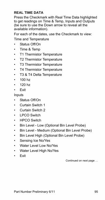
Part Number Preliminary 6/11 95
REAL TIME DATAPress the Checkmark with Real Time Data highlighted to get readings on Time & Temp, Inputs and Outputs (be sure to use the Down arrow to reveal all the available information).
For each of the dates, use the Checkmark to view:
Time and Temperature
• Status Off/On
• Time & Temp
• T1 Thermistor Temperature
• T2 Thermistor Temperature
• T3 Thermistor Temperature
• T4 Thermistor Temperature
• T3 & T4 Delta Temperature
• 100 hz
• 120 hz
• Exit
Inputs
• Status Off/On
• Curtain Switch 1
• Curtain Switch 2
• LPCO Switch
• HPCO Switch
• Bin Level - Low (Optional Bin Level Probe)
• Bin Level - Medium (Optional Bin Level Probe)
• Bin Level High (Optional Bin Level Probe)
• Sensing Ice No/Yes
• Water Level Low No/Yes
• Water Level High No/Yes
• ExitContinued on next page …
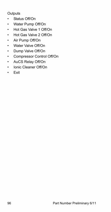
96 Part Number Preliminary 6/11
Outputs
• Status Off/On
• Water Pump Off/On
• Hot Gas Valve 1 Off/On
• Hot Gas Valve 2 Off/On
• Air Pump Off/On
• Water Valve Off/On
• Dump Valve Off/On
• Compressor Control Off/On
• AuCS Relay Off/On
• Ionic Cleaner Off/On
• Exit
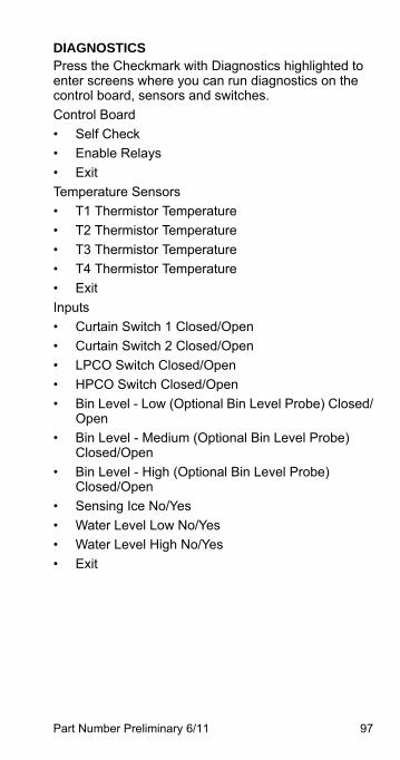
Part Number Preliminary 6/11 97
DIAGNOSTICSPress the Checkmark with Diagnostics highlighted to enter screens where you can run diagnostics on the control board, sensors and switches.
Control Board
• Self Check
• Enable Relays
• Exit
Temperature Sensors
• T1 Thermistor Temperature
• T2 Thermistor Temperature
• T3 Thermistor Temperature
• T4 Thermistor Temperature
• Exit
Inputs
• Curtain Switch 1 Closed/Open
• Curtain Switch 2 Closed/Open
• LPCO Switch Closed/Open
• HPCO Switch Closed/Open
• Bin Level - Low (Optional Bin Level Probe) Closed/Open
• Bin Level - Medium (Optional Bin Level Probe) Closed/Open
• Bin Level - High (Optional Bin Level Probe) Closed/Open
• Sensing Ice No/Yes
• Water Level Low No/Yes
• Water Level High No/Yes
• Exit
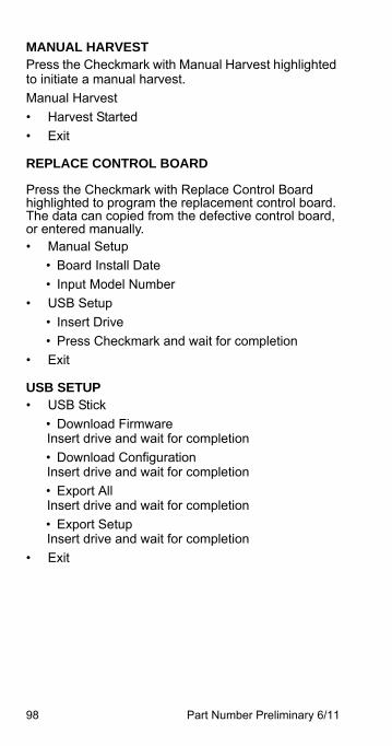
98 Part Number Preliminary 6/11
MANUAL HARVESTPress the Checkmark with Manual Harvest highlighted to initiate a manual harvest.
Manual Harvest
• Harvest Started
• Exit
REPLACE CONTROL BOARD
Press the Checkmark with Replace Control Board highlighted to program the replacement control board. The data can copied from the defective control board, or entered manually. • Manual Setup
• Board Install Date
• Input Model Number
• USB Setup
• Insert Drive
• Press Checkmark and wait for completion
• Exit
USB SETUP• USB Stick
• Download FirmwareInsert drive and wait for completion
• Download ConfigurationInsert drive and wait for completion
• Export AllInsert drive and wait for completion
• Export SetupInsert drive and wait for completion
• Exit
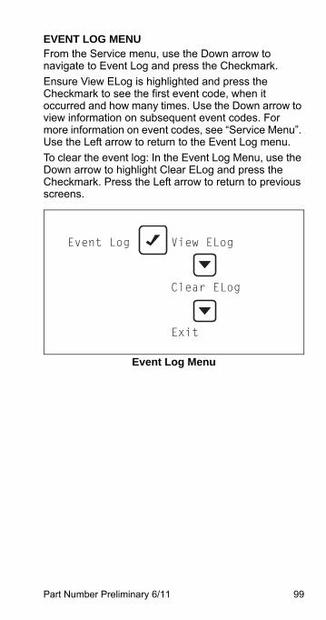
Part Number Preliminary 6/11 99
EVENT LOG MENUFrom the Service menu, use the Down arrow to navigate to Event Log and press the Checkmark.
Ensure View ELog is highlighted and press the Checkmark to see the first event code, when it occurred and how many times. Use the Down arrow to view information on subsequent event codes. For more information on event codes, see “Service Menu”. Use the Left arrow to return to the Event Log menu.
To clear the event log: In the Event Log Menu, use the Down arrow to highlight Clear ELog and press the Checkmark. Press the Left arrow to return to previous screens.
Event Log Menu
Event Log View ELog
Clear ELog
Exit
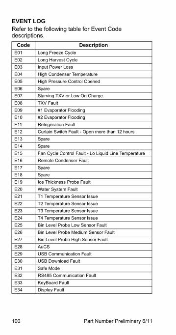
100 Part Number Preliminary 6/11
EVENT LOGRefer to the following table for Event Code descriptions.
Code Description
E01 Long Freeze Cycle
E02 Long Harvest Cycle
E03 Input Power Loss
E04 High Condenser Temperature
E05 High Pressure Control Opened
E06 Spare
E07 Starving TXV or Low On Charge
E08 TXV Fault
E09 #1 Evaporator Flooding
E10 #2 Evaporator Flooding
E11 Refrigeration Fault
E12 Curtain Switch Fault - Open more than 12 hours
E13 Spare
E14 Spare
E15 Fan Cycle Control Fault - Lo Liquid Line Temperature
E16 Remote Condenser Fault
E17 Spare
E18 Spare
E19 Ice Thickness Probe Fault
E20 Water System Fault
E21 T1 Temperature Sensor Issue
E22 T2 Temperature Sensor Issue
E23 T3 Temperature Sensor Issue
E24 T4 Temperature Sensor Issue
E25 Bin Level Probe Low Sensor Fault
E26 Bin Level Probe Medium Sensor Fault
E27 Bin Level Probe High Sensor Fault
E28 AuCS
E29 USB Communication Fault
E30 USB Download Fault
E31 Safe Mode
E32 RS485 Communication Fault
E33 KeyBoard Fault
E34 Display Fault

Part Number Preliminary 6/11 101
This Page Intentionally Left Blank
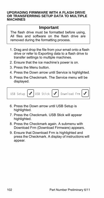
102 Part Number Preliminary 6/11
UPGRADING FIRMWARE WITH A FLASH DRIVE OR TRANSFERRING SETUP DATA TO MULTIPLE MACHINES
1. Drag and drop the file from your email onto a flash drive or refer to Exporting data to a flash drive to transfer settings to multiple machines.
2. Ensure that the ice machine’s power is on.
3. Press the Menu button.
4. Press the Down arrow until Service is highlighted.
5. Press the Checkmark. The Service menu will be displayed.
6. Press the Down arrow until USB Setup is highlighted.
7. Press the Checkmark. USB Stick will appear highlighted.
8. Press the Checkmark again. A submenu with Download Frm (Download Firmware) appears.
9. Ensure that Download Frm is highlighted and press the Checkmark. A display of instructions will appear.
ImportantThe flash drive must be formatted before using,All files and software on the flash drive areremoved during the formatting process.
USB Setup USB Stick Download Frm
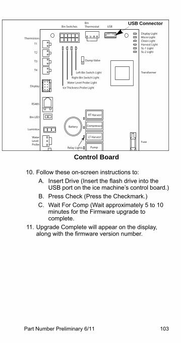
Part Number Preliminary 6/11 103
Control Board
10. Follow these on-screen instructions to:
A. Insert Drive (Insert the flash drive into the USB port on the ice machine’s control board.)
B. Press Check (Press the Checkmark.)
C. Wait For Comp (Wait approximately 5 to 10 minutes for the Firmware upgrade to complete.
11. Upgrade Complete will appear on the display, along with the firmware version number.
RT Harvest
Compressor
LT Harvest
Pump
Display LightMicro LightClean LightHarvest LightSL-1 LightSL-2 Light
Fuse
Thermistors
T1
T2
T3
T4
Display
RS485
Bin LED
WaterLevelProbe
LuminIce
Transformer
Battery
Bin SwitchesBin Thermostat USB
Ice Thickness Probe Light
Water Level Probe Light
Right Bin Switch Light
Left Bin Switch Light
Dump Valve
Relay Lights
USB Connector
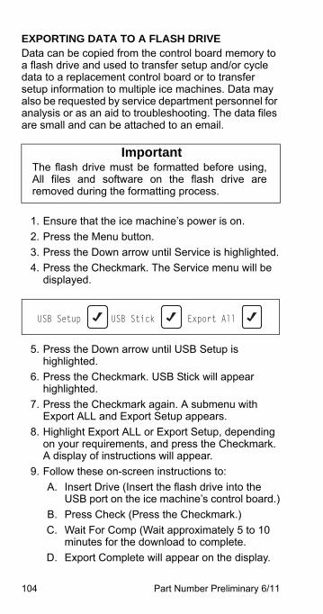
104 Part Number Preliminary 6/11
EXPORTING DATA TO A FLASH DRIVEData can be copied from the control board memory to a flash drive and used to transfer setup and/or cycle data to a replacement control board or to transfer setup information to multiple ice machines. Data may also be requested by service department personnel for analysis or as an aid to troubleshooting. The data files are small and can be attached to an email.
1. Ensure that the ice machine’s power is on.
2. Press the Menu button.
3. Press the Down arrow until Service is highlighted.
4. Press the Checkmark. The Service menu will be displayed.
5. Press the Down arrow until USB Setup is highlighted.
6. Press the Checkmark. USB Stick will appear highlighted.
7. Press the Checkmark again. A submenu with Export ALL and Export Setup appears.
8. Highlight Export ALL or Export Setup, depending on your requirements, and press the Checkmark. A display of instructions will appear.
9. Follow these on-screen instructions to:
A. Insert Drive (Insert the flash drive into the USB port on the ice machine’s control board.)
B. Press Check (Press the Checkmark.)
C. Wait For Comp (Wait approximately 5 to 10 minutes for the download to complete.
D. Export Complete will appear on the display.
ImportantThe flash drive must be formatted before using,All files and software on the flash drive areremoved during the formatting process.
USB Setup USB Stick Export All
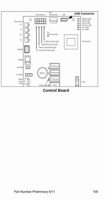
Part Number Preliminary 6/11 105
Control Board
RT Harvest
Compressor
LT Harvest
Pump
Display LightMicro LightClean LightHarvest LightSL-1 LightSL-2 Light
Fuse
Thermistors
T1
T2
T3
T4
Display
RS485
Bin LED
WaterLevelProbe
LuminIce
Transformer
Battery
Bin SwitchesBin Thermostat USB
Ice Thickness Probe Light
Water Level Probe Light
Right Bin Switch Light
Left Bin Switch Light
Dump Valve
Relay Lights
USB Connector
106 Part Number Preliminary 6/11
SAFE OPERATION MODEAllows the ice machine to operate up to 72 hours if the ice thickness probe and/or water level probe sensors fail.
• When the control board starts the safe mode an alert is flashed on the LCD display to notify the end-user they have a production problem.
• The control board automatically initiates and monitors the safe mode. The control will automatically exit the safe mode if a normal signal is received from the input.
• After 72 hours the control board will enter a standby mode and turn off
NOTE: The control board needs a five cycle history to operate safe mode. If five cycles have never been successfully completed the ice machine will shut-off.
• Example - The ice machine is a new installation and the water has not been turned on. The ice machine will stop after five cycles with five long freeze cycles and five water system faults in the event log.
Part Number Preliminary 6/11 107
Operational Checks
GENERALManitowoc ice machines are factory-operated and adjusted before shipment. Normally, new installations do not require any adjustment.
To ensure proper operation, always follow the Operational Checks:
• when starting the ice machine for the first time
• after a prolonged out of service period
• after cleaning and sanitizing
NOTE: Routine adjustments and maintenance procedures are not covered by the warranty.
ImportantRefrigeration compressors must be operatedfor a minimum break in period of 72 hoursbefore full ice production will be reached.
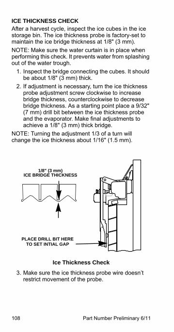
108 Part Number Preliminary 6/11
ICE THICKNESS CHECKAfter a harvest cycle, inspect the ice cubes in the ice storage bin. The ice thickness probe is factory-set to maintain the ice bridge thickness at 1/8" (3 mm).
NOTE: Make sure the water curtain is in place when performing this check. It prevents water from splashing out of the water trough.
1. Inspect the bridge connecting the cubes. It should be about 1/8" (3 mm) thick.
2. If adjustment is necessary, turn the ice thickness probe adjustment screw clockwise to increase bridge thickness, counterclockwise to decrease bridge thickness. As a starting point place a 9/32" (7 mm) drill bit between the ice thickness probe and the evaporator. Make final adjustments to achieve a 1/8" (3 mm) thick bridge.
NOTE: Turning the adjustment 1/3 of a turn will change the ice thickness about 1/16" (1.5 mm).
Ice Thickness Check
3. Make sure the ice thickness probe wire doesn’t restrict movement of the probe.
1/8" (3 mm) ICE BRIDGE THICKNESS
PLACE DRILL BIT HERE TO SET INTIAL GAP
Part Number Preliminary 6/11 109
Sequence of Operation
SELF CONTAINED AIR OR WATER COOLED
Single & Quad Evaporator Models
NOTE: The power button must be depressed and the water curtain/ice dampers must be in place on the evaporator before the ice machine will start.
Initial Start-Up or Start-Up After Automatic Shut-Off
1. Water Purge
Before the refrigerant compressor starts, the water pump and water dump solenoid energize to purge the ice machine of old water. This feature ensures that the ice making cycle starts with fresh water.
2. Refrigeration System Equalization and Start-Up
The harvest valve(s) and air pump(s) energize to equalize high and low side refrigeration pressure.
After 5 seconds the contactor energizes the compressor and supplies power to the condenser fan motor. After 5 seconds the harvest valve(s) and air pump(s) de-energize.
NOTE: The fan motor is wired through a fan cycle pressure control and will cycle on and off when the room temperatures is below 70°F (21°C).
110 Part Number Preliminary 6/11
Freeze Sequence
3. Prechill
The compressor lowers the temperature of the evaporator(s) before the water pump is energized. The water fill valve will energize and remain on until water completes the water level probe circuit.
4. Freeze
The water pump(s) energizes and water flows over the evaporator. After water contacts the water level probe the water fill valve de-energizes. The control board will automatically cycle the water fill valve on and off as needed during the first six minutes of the freeze cycle.
The freeze cycle continues until the six minute freeze lock expires and enough ice has formed to send a signal from the ice thickness probe to the control board.
Part Number Preliminary 6/11 111
Harvest Sequence
5. Water Purge
The air pump(s) (when used) and the harvest valve(s) open at the beginning of the water purge to divert hot refrigerant gas into the evaporator.
The water pump(s) continues to run, and the water dump valve energizes to purge the water in the water trough.
6. Harvest
The air pump (when used) remains energized and the harvest valve(s) remains open. The refrigerant gas warms the evaporator causing the cubes to slide, as a sheet, off the evaporator and into the storage bin.
Single evaporator models - The sliding sheet of cubes opens the water curtain/ice damper and bin switch.
The momentary opening and re-closing of the bin switch terminates the harvest sequence and returns the ice machine to the freeze sequence (Step 3 - 4.)
Multiple evaporator models - The sliding sheet of cubes opens the ice damper and bin switch. The momentary opening and re-closing of the bin switch de-energized the harvest valve for the evaporator. When all of the bin switches have opened and closed the ice machine will terminate the harvest sequence and return to the freeze sequence (Step 3 - 4.)
112 Part Number Preliminary 6/11
Automatic Shut-Off
7. Automatic Shut-Off
When the storage bin is full at the end of a harvest sequence, the sheet of cubes fails to clear the water curtain/ice damper and will hold it open. After the water curtain/ice damper is held open for 30 seconds, the ice machine shuts off. The ice machine remains off for 3 minutes before it can automatically restart.
The ice machine remains off until enough ice has been removed from the storage bin to allow the ice to fall clear of the water curtain or all of the ice dampers. As the water curtain/ice dampers swing back to the closed position, the bin switch re-closes and the ice machine restarts (steps 1 - 2), provided the 3 minute delay period is complete.
Control Board Timers
The control board has the following non-adjustable timers:
• The ice machine is locked into the freeze cycle for 6 minutes before a harvest cycle can be initiated. This can be overridden by initiating a manual harvest. Refer to “Manual Harvest” on page 98
• The maximum freeze time is 60 minutes at which time the control board automatically initiates a harvest sequence.
• The maximum harvest time is 3.5 minutes for single evaporators and 7 minutes for multiple evaporator models. The control board automatically initiates a freeze sequence when these times are exceeded.
• The maximum water fill is 6 minutes.
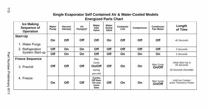
113P
art Num
ber Prelim
inary 6/11
Single Evaporator Self Contained Air & Water-Cooled ModelsEnergized Parts Chart
Ice MakingSequence of
Operation
WaterPump
HarvestValve(s)
Air Pump(s)*
Water Inlet Valve
Water Dump Valve
Contactor Coil Compressor Condenser
Fan MotorLengthof Time
Start-Up
1. Water PurgeOn Off Off Off On Off Off Off 45 Seconds
2. Refrigeration System Start-up
Off On On Off Off Off Off Off 5 Seconds
Off On On Off Off On On On 5 Seconds
Freeze Sequence
3. Prechill Off Off Off
May
Cycle On/Off
during
pre-chill
Off On On May CycleOn/Off
Initial Start-Up is 60 Seconds
30 Seconds thereafter
4. FreezeOn Off Off
Cycles Off then On one more time
Off On On May CycleOn/Off
Until Ice Contactw/Ice Thickness Probe
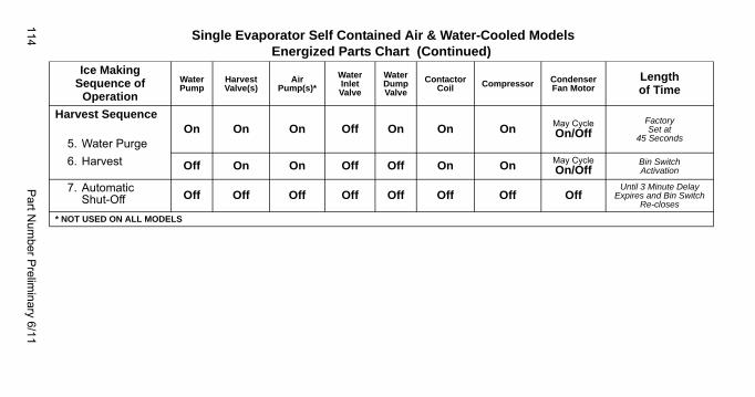
114P
art Num
ber Prelim
inary 6/11
Harvest Sequence
5. Water PurgeOn On On Off On On On May Cycle
On/OffFactorySet at
45 Seconds
6. Harvest Off On On Off Off On On May CycleOn/Off
Bin SwitchActivation
7. AutomaticShut-Off Off Off Off Off Off Off Off Off
Until 3 Minute Delay Expires and Bin Switch
Re-closes
* NOT USED ON ALL MODELS
Single Evaporator Self Contained Air & Water-Cooled ModelsEnergized Parts Chart (Continued)
Ice MakingSequence of
Operation
WaterPump
HarvestValve(s)
Air Pump(s)*
Water Inlet Valve
Water Dump Valve
Contactor Coil Compressor Condenser
Fan MotorLengthof Time
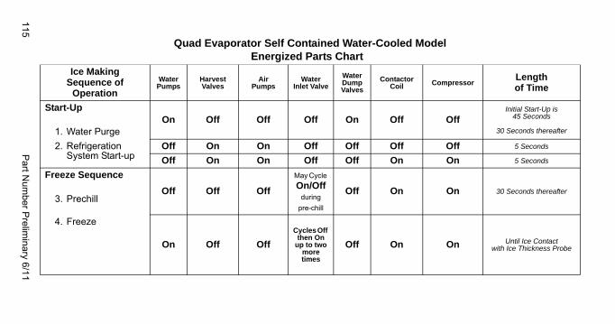
115P
art Num
ber Prelim
inary 6/11
Quad Evaporator Self Contained Water-Cooled ModelEnergized Parts Chart
Ice MakingSequence of
Operation
WaterPumps
HarvestValves
Air Pumps
Water Inlet Valve
Water Dump Valves
Contactor Coil Compressor
Lengthof Time
Start-Up
1. Water PurgeOn Off Off Off On Off Off
Initial Start-Up is 45 Seconds
30 Seconds thereafter
2. Refrigeration System Start-up
Off On On Off Off Off Off 5 Seconds
Off On On Off Off On On 5 Seconds
Freeze Sequence
3. PrechillOff Off Off
May Cycle On/Off
during
pre-chill
Off On On 30 Seconds thereafter
4. Freeze
On Off Off
Cycles Off then On
up to two more times
Off On On Until Ice Contactwith Ice Thickness Probe
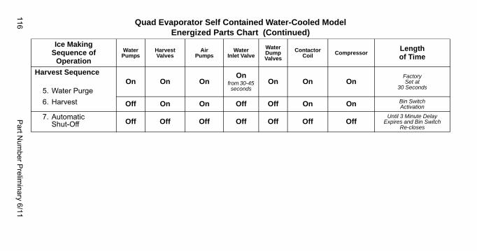
116P
art Num
ber Prelim
inary 6/11
Harvest Sequence
5. Water PurgeOn On On
Onfrom 30-45 seconds
On On OnFactorySet at
30 Seconds
6. Harvest Off On On Off Off On On Bin SwitchActivation
7. AutomaticShut-Off Off Off Off Off Off Off Off
Until 3 Minute Delay Expires and Bin Switch
Re-closes
Quad Evaporator Self Contained Water-Cooled ModelEnergized Parts Chart (Continued)
Ice MakingSequence of
Operation
WaterPumps
HarvestValves
Air Pumps
Water Inlet Valve
Water Dump Valves
Contactor Coil Compressor
Lengthof Time
Part Number Preliminary 6/11 117
REMOTE CONDENSER
Single Evaporator Models
NOTE: The power button must be depressed and the water curtain/ice dampers must be in place on the evaporator before the ice machine will start.
Initial Start-Up or Start-Up AfterAutomatic Shut-Off
1. Water Purge
Before the compressor starts, the water pump and water dump solenoid are energized for 45 seconds, to completely purge the ice machine of old water. This feature ensures that the ice making cycle starts with fresh water.
2. Refrigeration System Start-Up
The harvest valve, air pump and harvest pressure regulating (HPR) solenoid valves energize to equalize high and low side refrigeration pressure.
After 5 seconds the liquid line solenoid valve energizes and the contactor energizes the compressor and condenser fan motor.
118 Part Number Preliminary 6/11
Freeze Sequence
3. Prechill
The compressor is on for 30 seconds (60 seconds initial cycle) prior to water flow, to prechill the evaporator. The water fill valve is also energized and will remain on until water completes the water level probe circuit.
4. Freeze
The water pump(s) energizes and water flows over the evaporator. After water contacts the water level probe the water fill valve de-energizes. The control board will automatically cycle the water fill valve on and off as needed during the first six minutes of the freeze cycle.
The freeze cycle continues until the six minute freeze lock expires and enough ice has formed to send a signal from the ice thickness probe to the control board.
Part Number Preliminary 6/11 119
Harvest Sequence
5. Water Purge
The air pump (when used) the harvest valve(s) and harvest pressure regulating valve (HPR) open at the beginning of the water purge to divert hot refrigerant gas to the evaporator.
The water pump continues to run, and the water dump valve energizes to purge the water in the water trough.
6. Harvest
The HPR valve, air pump and harvest valve(s) remains open and the refrigerant gas warms the evaporator causing the cubes to slide, as a sheet, off the evaporator and into the storage bin. The sliding sheet of cubes opens the water curtain/ice damper and bin switch. The momentary opening and re-closing of the bin switch terminates the harvest sequence and returns the ice machine to the freeze sequence (Step 3 - 4.)
120 Part Number Preliminary 6/11
Automatic Shut-Off
7. Automatic Shut-Off
When the storage bin is full at the end of a harvest sequence, the sheet of cubes fails to clear the water curtain/ice damper and will hold it open. After the water curtain/ice damper is held open for 30 seconds, the ice machine shuts off. The ice machine remains off for 3 minutes before it can automatically restart.
The ice machine remains off until enough ice has been removed from the storage bin to allow the ice to drop clear of the water curtain/ice damper. As the water curtain/ice damper closes the bin switch the ice machine restarts (steps 1 - 2) provided the 3 minute delay period is complete.
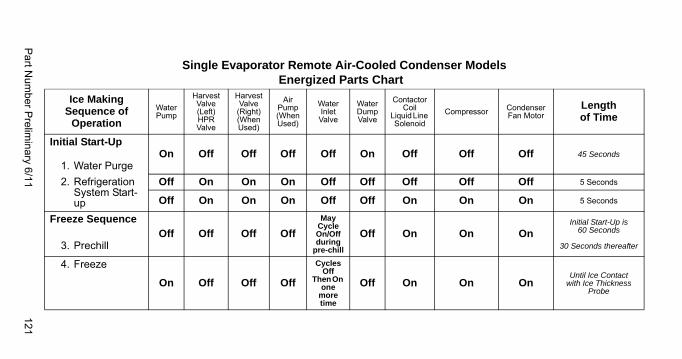
Part N
umber P
relimin
ary 6/11121
Single Evaporator Remote Air-Cooled Condenser ModelsEnergized Parts Chart
Ice MakingSequence of
Operation
WaterPump
HarvestValve(Left)HPR Valve
Harvest Valve
(Right)(When Used)
Air Pump(When Used)
Water Inlet Valve
Water Dump Valve
Contactor Coil
Liquid Line Solenoid
Compressor CondenserFan Motor
Lengthof Time
Initial Start-Up
1. Water PurgeOn Off Off Off Off On Off Off Off 45 Seconds
2. Refrigeration System Start-up
Off On On On Off Off Off Off Off 5 Seconds
Off On On On Off Off On On On 5 Seconds
Freeze Sequence
3. PrechillOff Off Off Off
May Cycle On/Off during
pre-chill
Off On On OnInitial Start-Up is
60 Seconds
30 Seconds thereafter
4. Freeze
On Off Off Off
Cycles Off
Then On one
more time
Off On On OnUntil Ice Contact
with Ice Thickness Probe
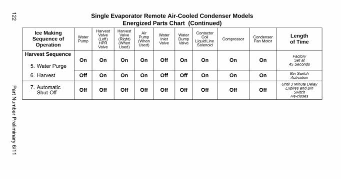
122P
art Num
ber Prelim
inary 6/11
Harvest Sequence
5. Water PurgeOn On On On Off On On On On
FactorySet at
45 Seconds
6. Harvest Off On On On Off Off On On On Bin SwitchActivation
7. AutomaticShut-Off Off Off Off Off Off Off Off Off Off
Until 3 Minute Delay Expires and Bin
SwitchRe-closes
Single Evaporator Remote Air-Cooled Condenser ModelsEnergized Parts Chart (Continued)
Ice MakingSequence of
Operation
WaterPump
HarvestValve(Left)HPR Valve
Harvest Valve
(Right)(When Used)
Air Pump(When Used)
Water Inlet Valve
Water Dump Valve
Contactor Coil
Liquid Line Solenoid
Compressor CondenserFan Motor
Lengthof Time
Part Number Preliminary 6/11 123
QUIETQUBE® MODELSNOTE: The power button must be depressed and the water curtain/ice dampers must be in place on the evaporator before the ice machine will start.
INITIAL START-UP OR START-UP AFTER AUTOMATIC SHUT-OFF1. Water Purge
Before the compressor starts, the water pump and water dump solenoid are energized to purge the ice machine of old water. This feature ensures that the ice making cycle starts with fresh water.
2. Refrigeration System Start-Up
Ice Machine Head Section:
The harvest valve(s) air pump(s) and liquid line solenoid valve energizes to equalize high and low side refrigeration pressure.
After 10 seconds the harvest valve(s) and air pump(s) de-energize.
ICVD Condensing Unit:
The low pressure switch closes and sends 24 volts to the control board. The control board completes the circuit and sends 24 volts to the contactor coil and energizes the compressor.
124 Part Number Preliminary 6/11
FREEZE SEQUENCE3. Pre chill
The water inlet valve energizes and the compressor lowers the temperature of the evaporator(s) before the water pump(s) is energized. The water fill valve will remain energized until water completes the water level probe circuit.
4. Freeze
The water pump(s) energizes and water flows over the evaporator. After water contacts the water level probe the water fill valve de-energizes. The control board will automatically cycle the water fill valve on and off as needed during the first six minutes of the freeze cycle.
The freeze cycle continues until the six minute freeze lock expires and enough ice has formed to send a signal from the ice thickness probe to the control board.
Part Number Preliminary 6/11 125
HARVEST SEQUENCE5. Water Purge
The air pump(s) (when used) and the harvest valve(s) open at the beginning of the water purge to divert refrigerant gas into the evaporator.
The water pump continues to run, and the water dump valve energizes to purge the water in the water trough.
ICVD Condensing Unit:
When the refrigerant pressure is low enough to open the fan cycling pressure control the condenser fan motor stops.
6. Harvest
The air pump(s) (when used) remains energized and the harvest valve(s) remains open. The refrigerant gas warms the evaporator causing the cubes to slide, as a sheet, off the evaporator and into the storage bin.
Single evaporator models - The sliding sheet of cubes opens the water curtain/ice damper and bin switch.
The momentary opening and re-closing of the bin switch will terminate the harvest sequence and return to the freeze sequence (Step 3 - 4.)
Twin & Quad evaporator models - The sliding sheet of cubes opens the ice damper and bin switch. The momentary opening and re-closing of the bin switch de-energizes the harvest valve for the evaporator. When all of the bin switches have opened and closed the ice machine will terminate the harvest sequence and return to the freeze sequence (Step 3 - 4.)
126 Part Number Preliminary 6/11
AUTOMATIC SHUT-OFF7. Automatic Shut-Off
Ice Machine Section: Shuts off when:
• The storage bin is full at the end of a harvest sequence.
• The sheet of cubes fails to clear the water curtain and holds it open.
• Ice contacts the bin level thermostat probe (when used).
• Ice damper is held down.
After the water curtain or ice damper are held open for 30 seconds, the ice machine shuts off. The ice machine remains off for 10 minutes before it can automatically restart.
ICVD Condensing Unit: The liquid line solenoid valve closes and the condensing unit pumps down. The LPCO opens and signals the control board. The control board starts a ten minute delay period and opens the 24 VAC circuit to the contactor coil, stopping the compressor and condenser fan motor.
RESTART AFTER AUTOMATIC SHUT-OFFThe ice machine remains off until enough ice has been removed to allow the ice to fall clear of the water curtain or ice damper. As the water curtain or ice damper swings back to the operating position, the bin switch re-closes and the ice machine restarts (steps 1 - 2), provided the 10 minute delay period is complete.
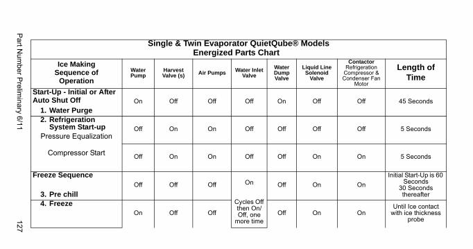
Part N
umber P
relimin
ary 6/11127
Single & Twin Evaporator QuietQube® ModelsEnergized Parts Chart
Ice MakingSequence of
Operation
WaterPump
HarvestValve (s) Air Pumps Water Inlet
Valve
Water Dump Valve
Liquid Line Solenoid
Valve
ContactorRefrigeration
Compressor & Condenser Fan
Motor
Length of Time
Start-Up - Initial or After Auto Shut Off
1. Water PurgeOn Off Off Off On Off Off 45 Seconds
2. Refrigeration System Start-up
Pressure Equalization
Compressor Start
Off On On Off Off Off Off 5 Seconds
Off On On Off Off On On 5 Seconds
Freeze Sequence
3. Pre chillOff Off Off On
Cycles Off then On/Off, one
more time
Off On On
Initial Start-Up is 60 Seconds
30 Seconds thereafter
4. FreezeOn Off Off Off On On
Until Ice contact with ice thickness
probe
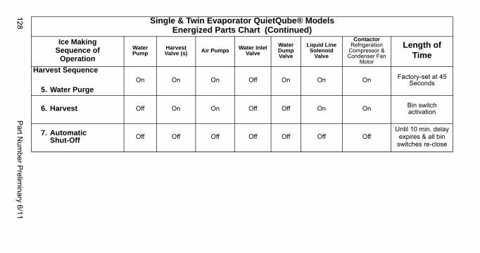
128P
art Num
ber Prelim
inary 6/11
Harvest Sequence
5. Water PurgeOn On On Off On On On Factory-set at 45
Seconds
6. Harvest Off On On Off Off On On Bin switch activation
7. AutomaticShut-Off Off Off Off Off Off Off Off
Until 10 min. delay expires & all bin
switches re-close
Single & Twin Evaporator QuietQube® ModelsEnergized Parts Chart (Continued)
Ice MakingSequence of
Operation
WaterPump
HarvestValve (s) Air Pumps Water Inlet
Valve
Water Dump Valve
Liquid Line Solenoid
Valve
ContactorRefrigeration
Compressor & Condenser Fan
Motor
Length of Time
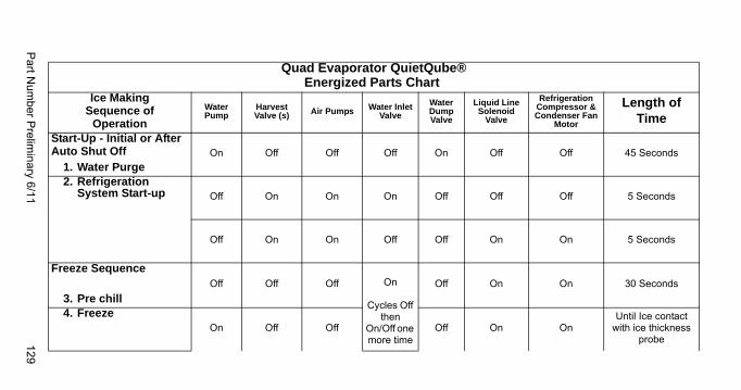
Part N
umber P
relimin
ary 6/11129
Quad Evaporator QuietQube®Energized Parts Chart
Ice MakingSequence of
Operation
WaterPump
HarvestValve (s) Air Pumps Water Inlet
Valve
Water Dump Valve
Liquid Line Solenoid
Valve
Refrigeration Compressor & Condenser Fan
Motor
Length of Time
Start-Up - Initial or After Auto Shut Off
1. Water PurgeOn Off Off Off On Off Off 45 Seconds
2. Refrigeration System Start-up Off On On On Off Off Off 5 Seconds
Off On On Off Off On On 5 Seconds
Freeze Sequence
3. Pre chillOff Off Off On
Cycles Off then
On/Off one more time
Off On On 30 Seconds
4. FreezeOn Off Off Off On On
Until Ice contact with ice thickness
probe
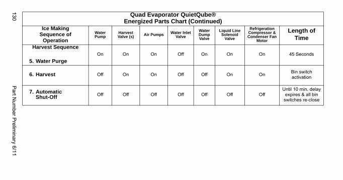
130P
art Num
ber Prelim
inary 6/11
Harvest Sequence
5. Water PurgeOn On On Off On On On 45 Seconds
6. Harvest Off On On Off Off On OnBin switch activation
7. AutomaticShut-Off Off Off Off Off Off Off Off
Until 10 min. delay expires & all bin
switches re-close
Quad Evaporator QuietQube®Energized Parts Chart (Continued)
Ice MakingSequence of
Operation
WaterPump
HarvestValve (s) Air Pumps Water Inlet
Valve
Water Dump Valve
Liquid Line Solenoid
Valve
Refrigeration Compressor & Condenser Fan
Motor
Length of Time
Part Number Preliminary 6/11 131
SAFETY TIMERSThe control board has the following non-adjustable safety timers:
• The ice machine is locked into the freeze cycle for 6 minutes before a harvest cycle can be initiated.This can be overridden by initiating a manual harvest. Refer to “Manual Harvest” on page 98
• The maximum freeze time is 60 minutes at which time the control board automatically initiates a harvest sequence (steps 5 & 6).
• The maximum harvest time is 3.5 minutes at which time the control board automatically ends the harvest cycle. When the bin switch is closed a freeze sequence initiates (steps 3 & 4). When the bin switch is open an automatic shutoff sequence initiates.
• The maximum water fill is 6 minutes.
WATER ASSIST HARVEST FEATURE
Twin & Quad Evaporators Only:
Typical duration of a Harvest sequence is less than 2.5 minutes. When the Harvest sequence time reaches 4 minutes, the following occurs:
4 minutes into a Harvest sequence: The water fill valve will energize to fill the trough with water.
5 minutes into a Harvest sequence: The water pump will energize and flow water over the evaporators.
The water fill valve and water pump remain on until all bin switches have been activated, or until the 7-minute Harvest sequence time limit is reached.

132 Part Number Preliminary 6/11
This Page Intentionally Left Blank
Part Number Preliminary 6/11 133
Troubleshooting
Safety LimitsIn addition to standard safety controls, the control board has built in safety limit controls which protect the ice machine from major component failures.
Safety limits are stored and indicated by the control board after three cycles. The number of cycles required to stop the ice machine varies for each safety limit.
• Safety Limit 1 all models - If the freeze time reaches 60 minutes, the control board automatically initiates a harvest cycle. If 6 consecutive 60-minute freeze cycles occur, the ice machine stops
• Safety Limit 2 single evaporator models - If the harvest time reaches 3.5 minutes, the control board automatically returns the ice machine to the freeze cycle. If 500 consecutive 3.5 minute harvest cycles occur, the ice machine stops.
• Safety Limit 2 Multiple evaporator models - If the harvest time reaches 7 minutes, the control board automatically returns the ice machine to the freeze cycle. If 500 consecutive 7 minute harvest cycles occur, the ice machine stops.
134 Part Number Preliminary 6/11
ANALYZING WHY A SAFETY LIMIT STOPPED THE ICE MACHINESafety limits are designed to stop the ice machine prior to major component failures, most often a minor problem or something external to the ice machine. This may be difficult to diagnose, as many external problems occur intermittently.
Example: An ice machine stops intermittently on safety limit #1 (long freeze times). The problem could be a low ambient temperature at night, a water pressure drop, the water is turned off one night a week, etc.
Refrigeration and electrical component failures will cause a safety limit trip. Eliminate all electrical components and external causes first. If it appears that the refrigeration system is causing the problem, use Manitowoc’s Freeze Cycle Refrigeration System Operational Analysis Table, along with detailed charts, checklists, and other references to determine the cause.
The following checklists are designed to assist the service technician in analysis. However, because there are many possible external problems, do not limit your diagnosis to only the items listed.
Part Number Preliminary 6/11 135
SAFETY LIMIT #1Freeze time exceeds 60 minutes for 6 consecutive freeze cycles.
Possible cause list
Water System
• Dirty/defective water level probe• Low water pressure (20 psig min.)• High water pressure (80 psig max.)• High water temperature (90°F/32.2°C max.)• Clogged water distribution tube• Dirty/defective water fill valve• Dirty/defective water dump valve• Defective water pump• Loss of water from sump area
Electrical System
• Low incoming voltage• Ice thickness probe out of adjustment• Harvest cycle not initiated electrically• Contactor not energizing• Compressor electrically non-operational• Defective fan cycling control• Defective fan motor
Miscellaneous
• Non-Manitowoc components• Improper refrigerant charge• Defective head pressure control• Defective harvest valve• Defective compressor• TXV starving or flooding (check bulb mounting)• Non-condensable in refrigeration system• Plugged or restricted high side refrigerant lines or
component• Restricted air flow/dirty condenser fins• High inlet air temperature• Condenser discharge air recirculation
136 Part Number Preliminary 6/11
SAFETY LIMIT #2Single Evaporator Models - Harvest time exceeds 3.5 minutes for 500 consecutive harvest cycles
Multiple Evaporator Models - Harvest time exceeds 7 minutes for 500 consecutive harvest cycles
Possible Cause Checklist
Improper Installation
• Refer to “Installation/Visual Inspection Checklist” page 162
Water System
• Water area (evaporator) dirty• Dirty/defective water dump valve• Vent tube not installed on water outlet drain• Water freezing behind evaporator• Plastic extrusions and gaskets not securely
mounted to the evaporator• Low water pressure (20 psig min.)• Loss of water from sump area• Clogged water distribution tube• Dirty/defective water fill valve• Defective water pump
Electrical System
• Ice thickness probe out of adjustment• Ice thickness probe dirty• Bin switch closed/defective• Premature harvest• I3300W Only - Harvest pressure solenoid valve
not energizing
Refrigeration System
• Non-Manitowoc components• Improper refrigerant charge• Defective head pressure control valve • Defective harvest valve• TXV flooding (check bulb mounting)• Defective fan cycling control• Water cooled only - Water inlet valve is incorrectly
adjusted or will not close during harvest cycle.• I3300W Only - Harvest pressure solenoid valve
not energizing.

Part Number Preliminary 6/11 137
This Page Intentionally Left Blank

138 Part Number Preliminary 6/11
This Page Intentionally Left Blank
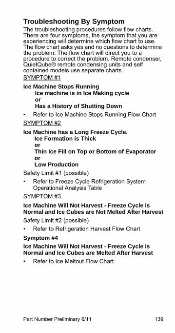
Part Number Preliminary 6/11 139
Troubleshooting By SymptomThe troubleshooting procedures follow flow charts. There are four symptoms, the symptom that you are experiencing will determine which flow chart to use. The flow chart asks yes and no questions to determine the problem. The flow chart will direct you to a procedure to correct the problem. Remote condenser, QuietQube® remote condensing units and self contained models use separate charts.SYMPTOM #1
Ice Machine Stops Running Ice machine is in Ice Making cycleorHas a History of Shutting Down
• Refer to Ice Machine Stops Running Flow Chart
SYMPTOM #2
Ice Machine has a Long Freeze Cycle. Ice Formation is Thick or Thin Ice Fill on Top or Bottom of Evaporator or Low Production
Safety Limit #1 (possible)
• Refer to Freeze Cycle Refrigeration System Operational Analysis Table
SYMPTOM #3
Ice Machine Will Not Harvest - Freeze Cycle is Normal and Ice Cubes are Not Melted After Harvest
Safety Limit #2 (possible)
• Refer to Refrigeration Harvest Flow Chart
Symptom #4
Ice Machine Will Not Harvest - Freeze Cycle is Normal and Ice Cubes are Melted After Harvest
• Refer to Ice Meltout Flow Chart
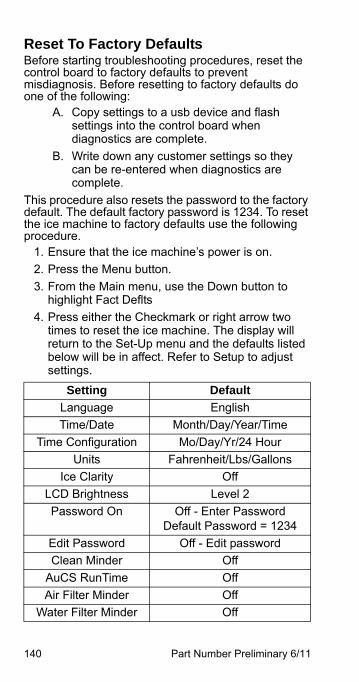
140 Part Number Preliminary 6/11
Reset To Factory DefaultsBefore starting troubleshooting procedures, reset the control board to factory defaults to prevent misdiagnosis. Before resetting to factory defaults do one of the following:
A. Copy settings to a usb device and flash settings into the control board when diagnostics are complete.
B. Write down any customer settings so they can be re-entered when diagnostics are complete.
This procedure also resets the password to the factory default. The default factory password is 1234. To reset the ice machine to factory defaults use the following procedure.
1. Ensure that the ice machine’s power is on.
2. Press the Menu button.
3. From the Main menu, use the Down button to highlight Fact Deflts
4. Press either the Checkmark or right arrow two times to reset the ice machine. The display will return to the Set-Up menu and the defaults listed below will be in affect. Refer to Setup to adjust settings.
Setting Default
Language English
Time/Date Month/Day/Year/Time
Time Configuration Mo/Day/Yr/24 Hour
Units Fahrenheit/Lbs/Gallons
Ice Clarity Off
LCD Brightness Level 2
Password On Off - Enter PasswordDefault Password = 1234
Edit Password Off - Edit password
Clean Minder Off
AuCS RunTime Off
Air Filter Minder Off
Water Filter Minder Off
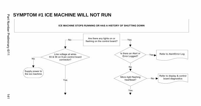
Part N
umber P
relimin
ary 6/11141
SYMPTOM #1 ICE MACHINE WILL NOT RUN
Micro light flashing heartbeat?
Yes
No
Are there any lights on or flashing on the control board?
ICE MACHINE STOPS RUNNING OR HAS A HISTORY OF SHUTTING DOWN
Yes
Refer to display & control board diagnostics
Is there an Alert or Error Logged?
Refer to Alert/Error LogYes
No
Yes
No
Line voltage at wires55 & 56 on 9 pin control board
connector?
Supply power to the ice machine
No
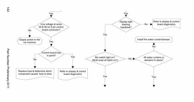
142P
art Num
ber Prelim
inary 6/11
Bin switch light on?(Multi evap all lights on?)
Control board fuse is good?
Yes
Yes
NoYes
Display lightflashing
heartbeat?No
Install the water curtain/damper.
All water curtains or dampers in place?
NoLine voltage at wires55 & 56 on 9 pin control
board connector?
Supply power to the ice machine
Yes
No
Yes
Refer to display & control board diagnostics
Replace fuse & determine which component caused fuse to blow
Refer to display & control board diagnostics
No
YesYes
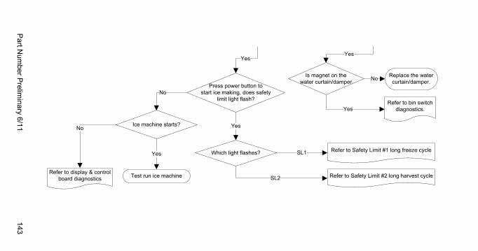
Part N
umber P
relimin
ary 6/11143
SL1
SL2
Press power button to start ice making, does safety
limit light flash?
Is magnet on the water curtain/damper
Yes
Replace the water curtain/damper. No
Yes
Ice machine starts?
No
No
Test run ice machine
Yes Which light flashes?
Yes
Yes
Refer to Safety Limit #2 long harvest cycle
Refer to Safety Limit #1 long freeze cycle
Refer to bin switch diagnostics.
Refer to display & control board diagnostics
144 Part Number Preliminary 6/11
Diagnosing an Ice Machine That Will Not Run
1. Verify primary voltage is supplied to ice machine and the fuse/circuit breaker is closed.
2. Verify the high pressure cutout is closed.
3. Verify control board fuse is okay. If the micro or display lights on the control board are energized the fuse is okay.
4. Verify all bin switches function properly. A defective bin switch can falsely indicate a full bin of ice.
5. Perform control board, display board and touch screen diagnostics. Be sure steps 1-6 were followed thoroughly. Intermittent problems are not usually related to the control board.
! WarningHigh (line) voltage is applied to the control board(terminals #55 and #56) at all times. Removingcontrol board fuse or pressing the power button willnot remove the power supplied to the control board.
Part Number Preliminary 6/11 145
DIAGNOSING A CONDENSING UNIT THAT WILL NOT RUNIf the ice machine water pump is not energized, refer to “Diagnosing an Ice Machine that Will Not Run.
1. Verify primary voltage is supplied to ice machine condensing unit and the fuse/circuit breaker is closed.
2. Test for 24 vac at terminals C & V - Replace transformer if 24 vac is not present.
3. Verify the low-pressure control is closed by testing for 24 vac @ terminals C & LPC.
4. Verify wires are intact and ice machine is calling for cooling by testing for 24 vac @ terminals C & HPC1.
5. Verify the high-pressure control is closed by testing for 24 vac at the contactor coil terminals.
6. Verify the contactor contacts are closed and line voltage is present across all lines.
7. Refer to compressor diagnostics.
146 Part Number Preliminary 6/11
COMPRESSOR ELECTRICAL DIAGNOSTICSThe compressor does not start or will trip repeatedly on overload.
Check Resistance (Ohm) Values
NOTE: Compressor windings can have very low ohm values. Use a properly calibrated meter.
Perform the resistance test after the compressor cools. The compressor dome should be cool enough to touch (below 120°F/49°C) to assure that the overload is closed and the resistance readings will be accurate.
SINGLE PHASE COMPRESSORS
1. Disconnect power then remove the wires from the compressor terminals.
2. The resistance values between C and S and between C and R, when added together, should equal the resistance value between S and R.
3. If the overload is open, there will be a resistance reading between S and R, and open readings between C and S and between C and R. Allow the compressor to cool, then check the readings again.
THREE PHASE COMPRESSORS
1. Disconnect power and remove the wires from the compressor terminals.
2. The resistance values between L1 and L2, between L2 and L3, and between L3 and L1 should all be equal.
3. If the overload is open, there will be open readings between L1 and L2, between L2 and L3, and between L3 and L1. Allow the compressor to cool, then check the readings again.
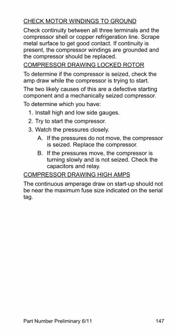
Part Number Preliminary 6/11 147
CHECK MOTOR WINDINGS TO GROUND
Check continuity between all three terminals and the compressor shell or copper refrigeration line. Scrape metal surface to get good contact. If continuity is present, the compressor windings are grounded and the compressor should be replaced.
COMPRESSOR DRAWING LOCKED ROTOR
To determine if the compressor is seized, check the amp draw while the compressor is trying to start.
The two likely causes of this are a defective starting component and a mechanically seized compressor.
To determine which you have:
1. Install high and low side gauges.
2. Try to start the compressor.
3. Watch the pressures closely.
A. If the pressures do not move, the compressor is seized. Replace the compressor.
B. If the pressures move, the compressor is turning slowly and is not seized. Check the capacitors and relay.
COMPRESSOR DRAWING HIGH AMPS
The continuous amperage draw on start-up should not be near the maximum fuse size indicated on the serial tag.
148 Part Number Preliminary 6/11
SYMPTOM #2 - SELF-CONTAINED AIR, WATER & REMOTE CONDENSER MODELS
Symptom #2 Low Production, Long Freeze
Ice Machine has a Long Freeze Cycle. Ice Formation is Thick or Thin on Top or Bottom of Evaporator or Low Production
How to Use the Freeze Cycle Refrigeration System Operational Analysis Table
GENERAL
These tables must be used with charts, checklists and other references to eliminate refrigeration components not listed on the tables and external items and problems which can cause good refrigeration components to appear defective.
The tables list five different defects that may affect the ice machine’s operation.
NOTE: A low-on-charge ice machine and a starving expansion valve have very similar characteristics and are listed under the same column.
NOTE: Before starting, see “Before Beginning Service” for a few questions to ask when talking to the ice machine owner.
Part Number Preliminary 6/11 149
PROCEDURE
Step 1 Complete the “Operation Analysis” column.
Read down the left “Operational Analysis” column. Perform all procedures and check all information listed. Each item in this column has supporting reference material to help analyze each step.
While analyzing each item separately, you may find an “external problem” causing a good refrigerant component to appear bad. Correct problems as they are found. If the operational problem is found, it is not necessary to complete the remaining procedures.
Step 2 Enter Checkmarks ().
Each time the actual findings of an item in the “Operational Analysis” column matches the published findings on the table, enter a Checkmark.
Example: Freeze cycle suction pressure is determined to be low. Enter a Checkmark in the “low” column.
Step 3 Add the Checkmarks listed under each of the four columns. Note the column number with the highest total and proceed to “Final Analysis.”
NOTE: If two columns have matching high numbers, a procedure was not performed properly, supporting material was not analyzed correctly or the problem component is not covered by the analysis table.

150P
art Num
ber Prelim
inary 6/11
SYMPTOM #2 - FREEZE CYCLE REFRIGERATION SYSTEM OPERATIONAL ANALYSIS TABLES
SINGLE EXPANSION VALVE SELF CONTAINED AIR, WATER & REMOTE CONDENSER Operational Analysis 1 2 3 4
Ice Production Air-Temperature Entering Condenser_____________Water Temperature Entering Ice Machine_________Published 24 hour ice production________________Calculated (actual) ice production_______________NOTE: The ice machine is operating properly if the ice fill patterns is normal and ice production is within 10% of charted capacity.
Installation and Water System
All installation and water related problems must be corrected before proceeding with chart.
Ice Formation PatternIce formation is extremely
thin on outlet ofevaporator
-or-No ice formation on the
entire evaporator
Ice formation is extremely thin on outlet
of evaporator-or-
No ice formation on entire evaporator
Ice formation normal-or-
Ice formation is extremely thin on inlet of
evaporator-or-
No ice formation on entire evaporator
Ice formation normal-or-
No ice formation on entire evaporator
Freeze Cycle Discharge Pressure_______ ______ ______1 minute Middle Endinto cycle
If discharge pressure is High or Low refer to freeze cycle high or low discharge pressure problem checklist page 166 to eliminate problems and/or components not listed on this table before proceeding.
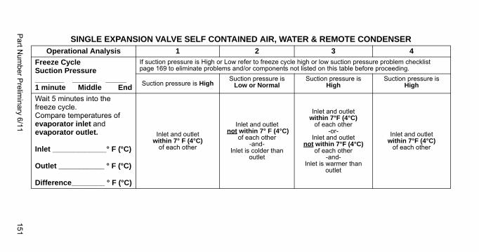
Part N
umber P
relimin
ary 6/11151
Freeze Cycle Suction Pressure_______ ______ _____1 minute Middle End
If suction pressure is High or Low refer to freeze cycle high or low suction pressure problem checklist page 169 to eliminate problems and/or components not listed on this table before proceeding.
Suction pressure is HighSuction pressure is
Low or NormalSuction pressure is
HighSuction pressure is
High
Wait 5 minutes into the freeze cycle.Compare temperatures of evaporator inlet and evaporator outlet.
Inlet _____________° F (°C)
Outlet ___________ ° F (°C)
Difference________ ° F (°C)
Inlet and outlet within 7° F (4°C)
of each other
Inlet and outlet not within 7° F (4°C)
of each other-and-
Inlet is colder than outlet
Inlet and outletwithin 7°F (4°C)
of each other-or-
Inlet and outletnot within 7°F (4°C)
of each other-and-
Inlet is warmer than outlet
Inlet and outletwithin 7°F (4°C)
of each other
SINGLE EXPANSION VALVE SELF CONTAINED AIR, WATER & REMOTE CONDENSER Operational Analysis 1 2 3 4
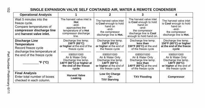
152P
art Num
ber Prelim
inary 6/11
Wait 5 minutes into the freeze cycle.Compare temperatures of compressor discharge line and harvest valve inlet.
The harvest valve inlet is Hot
-and-approaches the
temperature of a Hot compressor discharge
line.
The harvest valve inlet is Cool enough to hold
hand on-and-
the compressor discharge line is Hot.
The harvest valve inlet is Cool enough to hold
hand on-and-
the compressor discharge line is Cool
enough to hold hand on.
The harvest valve inlet is Cool enough to hold
hand on-and-
the compressor discharge line is Hot.
Discharge Line TemperatureRecord freeze cycle discharge line temperature at the end of the freeze cycle
_________°F (°C)
Discharge line temp. 150°F (65°C)
or higher at the end of the freeze cycle
--------------------------------I0850/I1000
Air & Water OnlyDischarge line temp.
140°F (60°C) or higher at the end of the freeze
cycle
Discharge line temp. 150°F (65°C)
or higher at the end of the freeze cycle
------------------------------I0850/I1000
Air & Water OnlyDischarge line temp.
140°F (60°C)or higher at the end of
the freeze cycle
Discharge line temp. less than
150°F (65°C) at the end of the freeze cycle
--------------------------------I0850/I1000
Air & Water OnlyDischarge line temp.
less than 140°F (60°C) at the end
of the freeze cycle
Discharge line temp. 150°F (65°C) or higher at the end of the freeze
cycle--------------------------------
I0850/I1000 Air & Water Only
Discharge line temp. 140°F (60°C)
or higher at the end of the freeze cycle
Final AnalysisEnter total number of boxes checked in each column.
Harvest ValveLeaking
Low On Charge-Or-
TXV StarvingTXV Flooding Compressor
SINGLE EXPANSION VALVE SELF CONTAINED AIR, WATER & REMOTE CONDENSER Operational Analysis 1 2 3 4
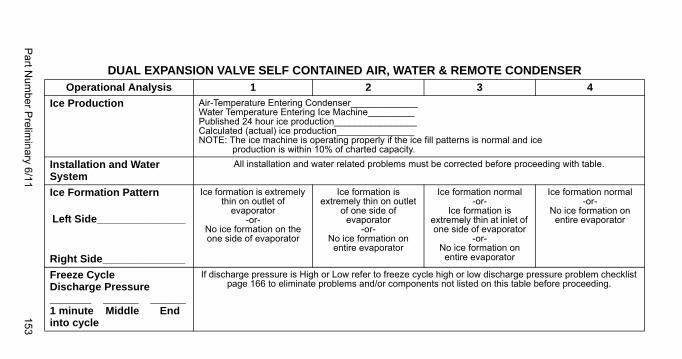
Part N
umber P
relimin
ary 6/11153
DUAL EXPANSION VALVE SELF CONTAINED AIR, WATER & REMOTE CONDENSER Operational Analysis 1 2 3 4
Ice Production Air-Temperature Entering Condenser_____________Water Temperature Entering Ice Machine_________Published 24 hour ice production________________Calculated (actual) ice production_______________NOTE: The ice machine is operating properly if the ice fill patterns is normal and ice production is within 10% of charted capacity.
Installation and Water System
All installation and water related problems must be corrected before proceeding with table.
Ice Formation Pattern
Left Side_______________
Right Side______________
Ice formation is extremely thin on outlet of
evaporator-or-
No ice formation on the one side of evaporator
Ice formation is extremely thin on outlet
of one side of evaporator
-or-No ice formation on
entire evaporator
Ice formation normal-or-
Ice formation is extremely thin at inlet of one side of evaporator
-or-No ice formation on entire evaporator
Ice formation normal-or-
No ice formation on entire evaporator
Freeze Cycle Discharge Pressure_______ ______ ______1 minute Middle Endinto cycle
If discharge pressure is High or Low refer to freeze cycle high or low discharge pressure problem checklist page 166 to eliminate problems and/or components not listed on this table before proceeding.
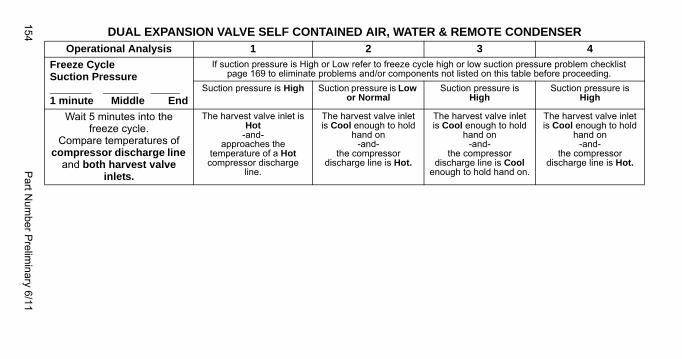
154P
art Num
ber Prelim
inary 6/11
Freeze Cycle Suction Pressure_______ ______ _____1 minute Middle End
If suction pressure is High or Low refer to freeze cycle high or low suction pressure problem checklist page 169 to eliminate problems and/or components not listed on this table before proceeding.
Suction pressure is High Suction pressure is Low or Normal
Suction pressure is High
Suction pressure is High
Wait 5 minutes into the freeze cycle.
Compare temperatures of compressor discharge line
and both harvest valve inlets.
The harvest valve inlet is Hot
-and-approaches the
temperature of a Hot compressor discharge
line.
The harvest valve inlet is Cool enough to hold
hand on-and-
the compressor discharge line is Hot.
The harvest valve inlet is Cool enough to hold
hand on-and-
the compressor discharge line is Cool
enough to hold hand on.
The harvest valve inlet is Cool enough to hold
hand on-and-
the compressor discharge line is Hot.
DUAL EXPANSION VALVE SELF CONTAINED AIR, WATER & REMOTE CONDENSER Operational Analysis 1 2 3 4
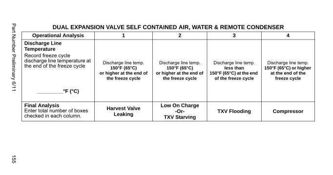
Part N
umber P
relimin
ary 6/11155
Discharge Line TemperatureRecord freeze cycle discharge line temperature at the end of the freeze cycle
_________°F (°C)
Discharge line temp. 150°F (65°C)
or higher at the end of the freeze cycle
Discharge line temp. 150°F (65°C)
or higher at the end of the freeze cycle
Discharge line temp. less than
150°F (65°C) at the end of the freeze cycle
Discharge line temp. 150°F (65°C) or higher
at the end of the freeze cycle
Final AnalysisEnter total number of boxes checked in each column.
Harvest ValveLeaking
Low On Charge-Or-
TXV StarvingTXV Flooding Compressor
DUAL EXPANSION VALVE SELF CONTAINED AIR, WATER & REMOTE CONDENSER Operational Analysis 1 2 3 4
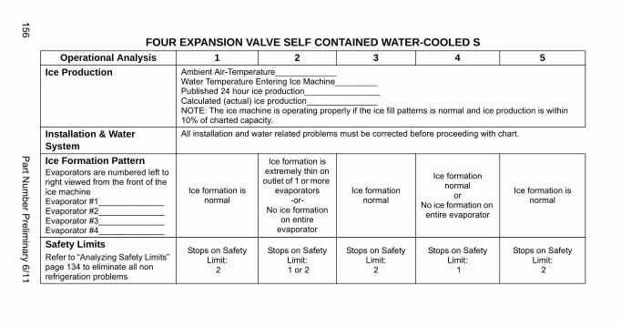
156P
art Num
ber Prelim
inary 6/11
FOUR EXPANSION VALVE SELF CONTAINED WATER-COOLED SOperational Analysis 1 2 3 4 5
Ice Production Ambient Air-Temperature_____________Water Temperature Entering Ice Machine_________Published 24 hour ice production________________Calculated (actual) ice production_______________NOTE: The ice machine is operating properly if the ice fill patterns is normal and ice production is within 10% of charted capacity.
Installation & Water System
All installation and water related problems must be corrected before proceeding with chart.
Ice Formation PatternEvaporators are numbered left to right viewed from the front of the ice machineEvaporator #1______________Evaporator #2______________Evaporator #3______________Evaporator #4______________
Ice formation is normal
Ice formation is extremely thin on outlet of 1 or more
evaporators-or-
No ice formation on entire
evaporator
Ice formation normal
Ice formation normal
orNo ice formation on
entire evaporator
Ice formation is normal
Safety LimitsRefer to “Analyzing Safety Limits” page 134 to eliminate all non refrigeration problems
Stops on Safety Limit:
2
Stops on Safety Limit: 1 or 2
Stops on Safety Limit:
2
Stops on Safety Limit:
1
Stops on Safety Limit:
2
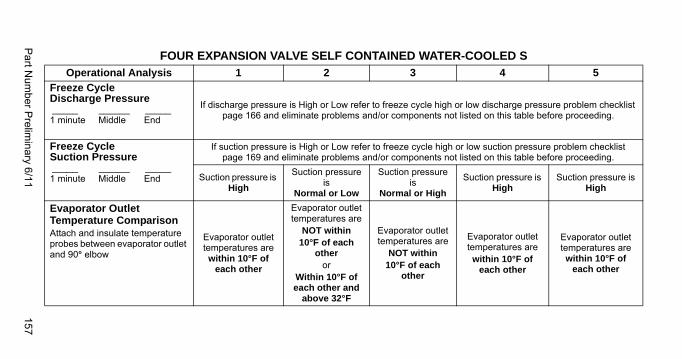
Part N
umber P
relimin
ary 6/11157
Freeze Cycle Discharge Pressure_____ ______ _____1 minute Middle End
If discharge pressure is High or Low refer to freeze cycle high or low discharge pressure problem checklist page 166 and eliminate problems and/or components not listed on this table before proceeding.
Freeze Cycle Suction Pressure_____ ______ _____1 minute Middle End
If suction pressure is High or Low refer to freeze cycle high or low suction pressure problem checklist page 169 and eliminate problems and/or components not listed on this table before proceeding.
Suction pressure is High
Suction pressure is
Normal or Low
Suction pressure is
Normal or High
Suction pressure is High
Suction pressure is High
Evaporator Outlet Temperature ComparisonAttach and insulate temperature probes between evaporator outlet and 90° elbow
Evaporator outlet temperatures are within 10°F of
each other
Evaporator outlet temperatures are
NOT within 10°F of each
otheror
Within 10°F of each other and
above 32°F
Evaporator outlet temperatures are
NOT within 10°F of each
other
Evaporator outlet temperatures are within 10°F of
each other
Evaporator outlet temperatures are within 10°F of
each other
FOUR EXPANSION VALVE SELF CONTAINED WATER-COOLED SOperational Analysis 1 2 3 4 5
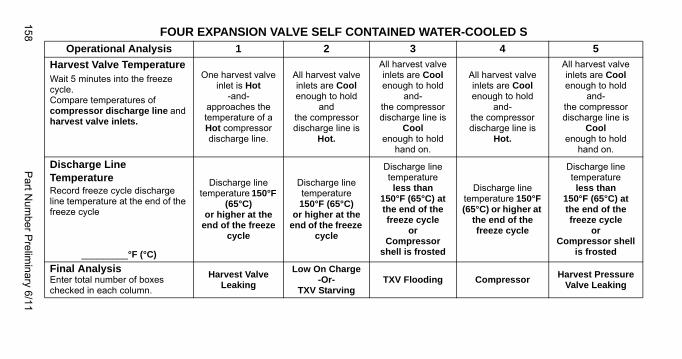
158P
art Num
ber Prelim
inary 6/11
Harvest Valve Temperature Wait 5 minutes into the freeze cycle.Compare temperatures of compressor discharge line and harvest valve inlets.
One harvest valve inlet is Hot
-and-approaches the temperature of a Hot compressor discharge line.
All harvest valve inlets are Cool enough to hold
andthe compressor discharge line is
Hot.
All harvest valve inlets are Cool enough to hold
and-the compressor discharge line is
Coolenough to hold
hand on.
All harvest valve inlets are Cool enough to hold
and-the compressor discharge line is
Hot.
All harvest valve inlets are Cool enough to hold
and-the compressor discharge line is
Coolenough to hold
hand on.
Discharge Line TemperatureRecord freeze cycle discharge line temperature at the end of the freeze cycle
_________°F (°C)
Discharge line temperature 150°F
(65°C) or higher at the
end of the freeze cycle
Discharge line temperature 150°F (65°C)
or higher at the end of the freeze
cycle
Discharge line temperature less than
150°F (65°C) at the end of the freeze cycle
orCompressor
shell is frosted
Discharge line temperature 150°F (65°C) or higher at
the end of the freeze cycle
Discharge line temperature less than
150°F (65°C) atthe end of the freeze cycle
orCompressor shell
is frosted
Final AnalysisEnter total number of boxes checked in each column.
Harvest Valve Leaking
Low On Charge-Or-
TXV StarvingTXV Flooding Compressor
Harvest Pressure Valve Leaking
FOUR EXPANSION VALVE SELF CONTAINED WATER-COOLED SOperational Analysis 1 2 3 4 5
Part Number Preliminary 6/11 159
The following are the procedures for completing each step of the Freeze Cycle Refrigeration System Operational Analysis Tables. Each procedure must be performed exactly for the table to work correctly.
Before Beginning Service
Ice machines may experience operational problems only during certain times of the day or night. A machine may function properly while it is being serviced, but malfunctions later. Information provided by the user can help the technician start in the right direction, and may be a determining factor in the final diagnosis.
Ask these questions before beginning service:
• When does the ice machine malfunction? (night, day, all the time, only during the Freeze cycle, etc.)
• When do you notice low ice production? (one day a week, every day, on weekends, etc.)
• Can you describe exactly what the ice machine seems to be doing?
• Has anyone been working on the ice machine?
• During “store shutdown,” is the circuit breaker, water supply or air temperature altered?
• Is there any reason why incoming water pressure might rise or drop substantially?
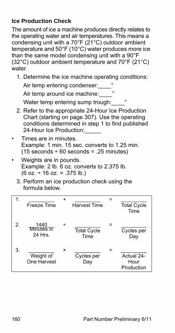
160 Part Number Preliminary 6/11
Ice Production Check
The amount of ice a machine produces directly relates to the operating water and air temperatures. This means a condensing unit with a 70°F (21°C) outdoor ambient temperature and 50°F (10°C) water produces more ice than the same model condensing unit with a 90°F (32°C) outdoor ambient temperature and 70°F (21°C) water.
1. Determine the ice machine operating conditions:
Air temp entering condenser:____°
Air temp around ice machine:____°
Water temp entering sump trough:____°
2. Refer to the appropriate 24-Hour Ice Production Chart (starting on page 307). Use the operating conditions determined in step 1 to find published 24-Hour Ice Production:_____
• Times are in minutes.Example: 1 min. 15 sec. converts to 1.25 min.(15 seconds ÷ 60 seconds = .25 minutes)
• Weights are in pounds.Example: 2 lb. 6 oz. converts to 2.375 lb.(6 oz. ÷ 16 oz. = .375 lb.)
3. Perform an ice production check using the formula below.
1. _________Freeze Time
+ _________Harvest Time
= _________Total Cycle
Time
2. 1440_________Minutes in
24 Hrs.
÷ _________Total Cycle
Time
= _________Cycles per
Day
3. _________Weight of
One Harvest
× _________Cycles per
Day
= _________Actual 24-
HourProduction
Part Number Preliminary 6/11 161
Weighing the ice is the only 100% accurate check. However, if the ice pattern is normal and the 1/8 in. thickness is maintained, the ice slab weights listed with the 24-Hour Ice Production Charts may be used.
4. Compare the results of step 3 with step 2. Ice production checks that are within 10% of the chart are considered normal. If they match closely, determine if:
• Another ice machine is required.
• More storage capacity is required.
• Relocating the existing equipment to lower the load conditions is required.
Contact the local Manitowoc Distributor for information on available options and accessories.
162 Part Number Preliminary 6/11
Installation/Visual Inspection Checklist
Inadequate Clearances
• Check all clearances on sides, back and top.
Ice machine is not level
• Level the ice machine
Condenser is dirty
• Clean the condenser
Water filtration is plugged (if used)
• Install a new water filter
Water drains are not run separately and/or are not vented
• Run and vent drains according to the Installation Manual
Line set is improperly installed
• Reinstall according to the Installation Manual
Part Number Preliminary 6/11 163
Water System Checklist
A water-related problem often causes the same symptoms as a refrigeration system component malfunction.
Water system problems must be identified and eliminated prior to replacing refrigeration components.
Water area (evaporator) is dirty
• Clean as needed
Water inlet pressure not between 20 and 80 psig (1-5 Bar, 138-552 kPa).
• Install water regulator or increase water pressure
Incoming water temperature is not between 35°F (2°C) and 90°F (32°C)
• If too hot, check the hot water line check valves in other store equipment
Water filtration is plugged (if used)
• Install a new water filter
Water dump valve leaking during the Freeze cycle
• Clean/replace dump valve as needed
Vent tube is not installed on water outlet drain
• See Installation Instructions
Hoses, fittings, etc., are leaking water
• Repair/replace as needed
Water fill valve is stuck open or closed
• Clean/replace as needed
Water is leaking out of the sump trough area
• Stop the water loss
Uneven water flow across the evaporator
• Clean the ice machine
Plastic extrusions and gaskets are not secured to the evaporator
• Remount/replace as needed
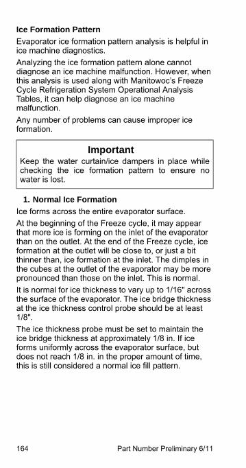
164 Part Number Preliminary 6/11
Ice Formation Pattern
Evaporator ice formation pattern analysis is helpful in ice machine diagnostics.
Analyzing the ice formation pattern alone cannot diagnose an ice machine malfunction. However, when this analysis is used along with Manitowoc’s Freeze Cycle Refrigeration System Operational Analysis Tables, it can help diagnose an ice machine malfunction.
Any number of problems can cause improper ice formation.
1. Normal Ice Formation
Ice forms across the entire evaporator surface.
At the beginning of the Freeze cycle, it may appear that more ice is forming on the inlet of the evaporator than on the outlet. At the end of the Freeze cycle, ice formation at the outlet will be close to, or just a bit thinner than, ice formation at the inlet. The dimples in the cubes at the outlet of the evaporator may be more pronounced than those on the inlet. This is normal.
It is normal for ice thickness to vary up to 1/16" across the surface of the evaporator. The ice bridge thickness at the ice thickness control probe should be at least1/8".
The ice thickness probe must be set to maintain the ice bridge thickness at approximately 1/8 in. If ice forms uniformly across the evaporator surface, but does not reach 1/8 in. in the proper amount of time, this is still considered a normal ice fill pattern.
ImportantKeep the water curtain/ice dampers in place whilechecking the ice formation pattern to ensure nowater is lost.
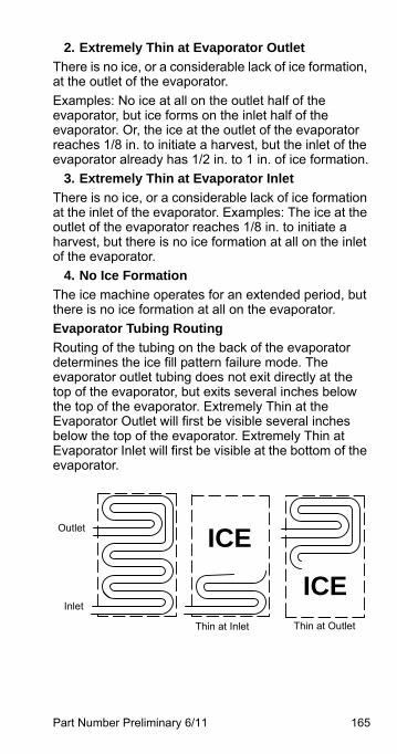
Part Number Preliminary 6/11 165
2. Extremely Thin at Evaporator Outlet
There is no ice, or a considerable lack of ice formation, at the outlet of the evaporator.
Examples: No ice at all on the outlet half of the evaporator, but ice forms on the inlet half of the evaporator. Or, the ice at the outlet of the evaporator reaches 1/8 in. to initiate a harvest, but the inlet of the evaporator already has 1/2 in. to 1 in. of ice formation.
3. Extremely Thin at Evaporator Inlet
There is no ice, or a considerable lack of ice formation at the inlet of the evaporator. Examples: The ice at the outlet of the evaporator reaches 1/8 in. to initiate a harvest, but there is no ice formation at all on the inlet of the evaporator.
4. No Ice Formation
The ice machine operates for an extended period, but there is no ice formation at all on the evaporator.
Evaporator Tubing Routing
Routing of the tubing on the back of the evaporator determines the ice fill pattern failure mode. The evaporator outlet tubing does not exit directly at the top of the evaporator, but exits several inches below the top of the evaporator. Extremely Thin at the Evaporator Outlet will first be visible several inches below the top of the evaporator. Extremely Thin at Evaporator Inlet will first be visible at the bottom of the evaporator.
Outlet
Inlet
Thin at OutletThin at Inlet
ICE
ICE
166 Part Number Preliminary 6/11
Analyzing Discharge Pressure in the Freeze Cycle
1. Determine the ice machine operating conditions:
Air temp. entering condenser______
Air temp. around ice machine______
Water temp. entering sump trough______
2. Refer to Operating Pressure table (starting on page 307) for ice machine being checked.
Use the operating conditions determined in step 1 to find the published normal discharge pressures.
Freeze Cycle______
Harvest Cycle______
3. Perform an actual discharge pressure check.
4. Compare the actual discharge pressure (step 3) with the published discharge pressure (step 2).
The discharge pressure is normal when the actual pressure falls within the published pressure range for the ice machine’s operating conditions. It is normal for the discharge pressure to be higher at the beginning of the Freeze cycle (when load is greatest), then drop throughout the Freeze cycle.
Freeze Cyclepsig (kPa)
1 Minute into theFreeze Cycle __________
Middle of Freeze Cycle __________
End of Freeze Cycle __________
Part Number Preliminary 6/11 167
FREEZE CYCLE DISCHARGE PRESSURE HIGH CHECKLIST
Improper Installation
• Refer to “Installation/Visual Inspection Checklist” (page 162)
Air Condenser
• Dirty condenser filter
• Dirty condenser fins
• High inlet air temperature
• Condenser discharge air recirculation
• Defective fan cycling control (page 273)
• Defective fan motor
• Defective head pressure control valve {Remote}
Water Condenser
• Low water pressure [20 psig (138 kPa) min.]
• High inlet water temperature (90°F/32°C max.)
• Dirty condenser
• Dirty/Defective water regulating valve
• Water regulating valve out of adjustment
Other
• Overcharged
• Non-condensable (air) in system
• Wrong type of refrigerant
• Non-Manitowoc components in system
• High side refrigerant lines/component restricted
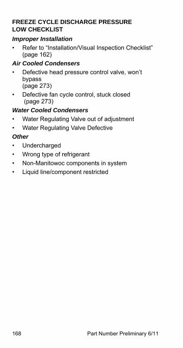
168 Part Number Preliminary 6/11
FREEZE CYCLE DISCHARGE PRESSURELOW CHECKLIST
Improper Installation
• Refer to “Installation/Visual Inspection Checklist” (page 162)
Air Cooled Condensers
• Defective head pressure control valve, won’t bypass(page 273)
• Defective fan cycle control, stuck closed (page 273)
Water Cooled Condensers
• Water Regulating Valve out of adjustment
• Water Regulating Valve Defective
Other
• Undercharged
• Wrong type of refrigerant
• Non-Manitowoc components in system
• Liquid line/component restricted
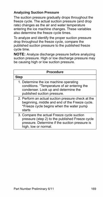
Part Number Preliminary 6/11 169
Analyzing Suction Pressure
The suction pressure gradually drops throughout the freeze cycle. The actual suction pressure (and drop rate) changes as the air and water temperature entering the ice machine changes. These variables also determine the freeze cycle times.
To analyze and identify the proper suction pressure drop throughout the freeze cycle, compare the published suction pressure to the published freeze cycle time.
NOTE: Analyze discharge pressure before analyzing suction pressure. High or low discharge pressure may be causing high or low suction pressure.
Procedure
Step
1. Determine the ice machine operating conditions. *Temperature of air entering the condenser. Look up and determine the published suction pressure.
2. Perform an actual suction pressure check at the beginning, middle and end of the Freeze cycle. *Freeze cycle begins when the water pump starts
3. Compare the actual Freeze cycle suction pressure (step 2) to the published Freeze cycle pressure. Determine if the suction pressure is high, low or normal.
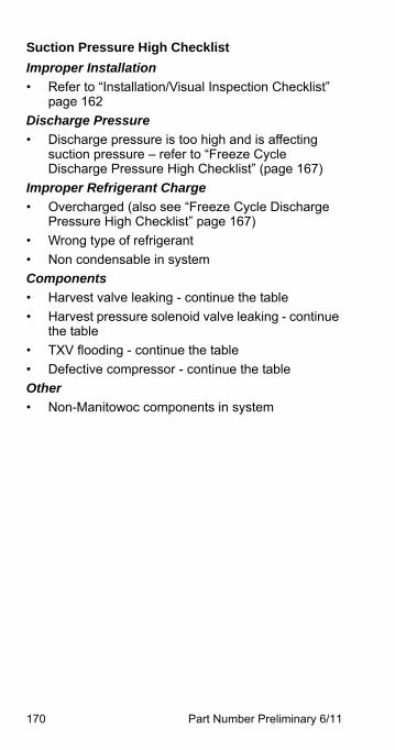
170 Part Number Preliminary 6/11
Suction Pressure High Checklist
Improper Installation
• Refer to “Installation/Visual Inspection Checklist” page 162
Discharge Pressure
• Discharge pressure is too high and is affecting suction pressure – refer to “Freeze Cycle Discharge Pressure High Checklist” (page 167)
Improper Refrigerant Charge
• Overcharged (also see “Freeze Cycle Discharge Pressure High Checklist” page 167)
• Wrong type of refrigerant
• Non condensable in system
Components
• Harvest valve leaking - continue the table
• Harvest pressure solenoid valve leaking - continue the table
• TXV flooding - continue the table
• Defective compressor - continue the table
Other
• Non-Manitowoc components in system
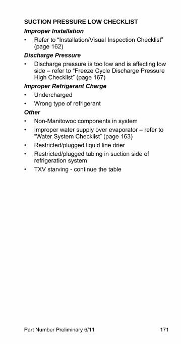
Part Number Preliminary 6/11 171
SUCTION PRESSURE LOW CHECKLIST
Improper Installation
• Refer to “Installation/Visual Inspection Checklist” (page 162)
Discharge Pressure
• Discharge pressure is too low and is affecting low side – refer to “Freeze Cycle Discharge Pressure High Checklist” (page 167)
Improper Refrigerant Charge
• Undercharged
• Wrong type of refrigerant
Other
• Non-Manitowoc components in system
• Improper water supply over evaporator – refer to “Water System Checklist” (page 163)
• Restricted/plugged liquid line drier
• Restricted/plugged tubing in suction side of refrigeration system
• TXV starving - continue the table
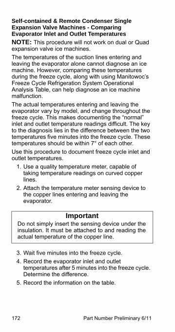
172 Part Number Preliminary 6/11
Self-contained & Remote Condenser Single Expansion Valve Machines - Comparing Evaporator Inlet and Outlet Temperatures
NOTE: This procedure will not work on dual or Quad expansion valve ice machines.
The temperatures of the suction lines entering and leaving the evaporator alone cannot diagnose an ice machine. However, comparing these temperatures during the freeze cycle, along with using Manitowoc’s Freeze Cycle Refrigeration System Operational Analysis Table, can help diagnose an ice machine malfunction.
The actual temperatures entering and leaving the evaporator vary by model, and change throughout the freeze cycle. This makes documenting the “normal” inlet and outlet temperature readings difficult. The key to the diagnosis lies in the difference between the two temperatures five minutes into the freeze cycle. These temperatures should be within 7° of each other.
Use this procedure to document freeze cycle inlet and outlet temperatures.
1. Use a quality temperature meter, capable of taking temperature readings on curved copper lines.
2. Attach the temperature meter sensing device to the copper lines entering and leaving the evaporator.
3. Wait five minutes into the freeze cycle.
4. Record the evaporator inlet and outlet temperatures after 5 minutes into the freeze cycle. Determine the difference.
5. Record the information on the table.
ImportantDo not simply insert the sensing device under theinsulation. It must be attached to and reading theactual temperature of the copper line.
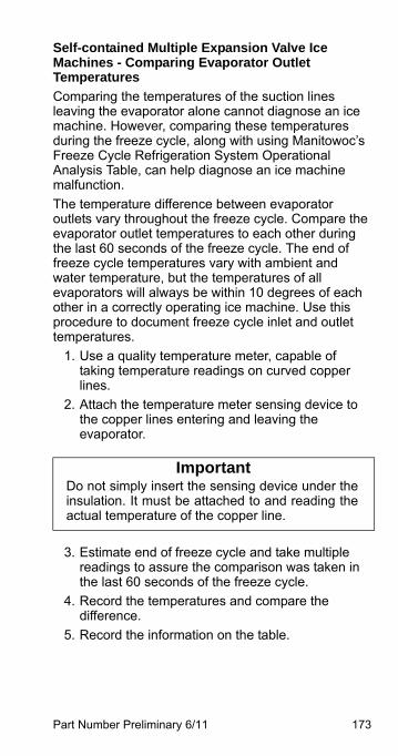
Part Number Preliminary 6/11 173
Self-contained Multiple Expansion Valve Ice Machines - Comparing Evaporator Outlet Temperatures
Comparing the temperatures of the suction lines leaving the evaporator alone cannot diagnose an ice machine. However, comparing these temperatures during the freeze cycle, along with using Manitowoc’s Freeze Cycle Refrigeration System Operational Analysis Table, can help diagnose an ice machine malfunction.
The temperature difference between evaporator outlets vary throughout the freeze cycle. Compare the evaporator outlet temperatures to each other during the last 60 seconds of the freeze cycle. The end of freeze cycle temperatures vary with ambient and water temperature, but the temperatures of all evaporators will always be within 10 degrees of each other in a correctly operating ice machine. Use this procedure to document freeze cycle inlet and outlet temperatures.
1. Use a quality temperature meter, capable of taking temperature readings on curved copper lines.
2. Attach the temperature meter sensing device to the copper lines entering and leaving the evaporator.
3. Estimate end of freeze cycle and take multiple readings to assure the comparison was taken in the last 60 seconds of the freeze cycle.
4. Record the temperatures and compare the difference.
5. Record the information on the table.
ImportantDo not simply insert the sensing device under theinsulation. It must be attached to and reading theactual temperature of the copper line.
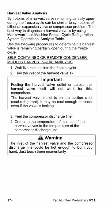
174 Part Number Preliminary 6/11
Harvest Valve Analysis
Symptoms of a harvest valve remaining partially open during the freeze cycle can be similar to symptoms of either an expansion valve or compressor problem. The best way to diagnose a harvest valve is by using Manitowoc’s Ice Machine Freeze Cycle Refrigeration System Operational Analysis Table.
Use the following procedures to determine if a harvest valve is remaining partially open during the freeze cycle.
SELF-CONTAINED OR REMOTE CONDENSER MODELS HARVEST VALVE ANALYSIS
1. Wait five minutes into the freeze cycle.
2. Feel the inlet of the harvest valve(s).
3. Feel the compressor discharge line.
4. Compare the temperature of the inlet of the harvest valves to the temperature of the compressor discharge line.
ImportantFeeling the harvest valve outlet or across theharvest valve itself will not work for thiscomparison.The harvest valve outlet is on the suction side(cool refrigerant). It may be cool enough to toucheven if the valve is leaking.
! WarningThe inlet of the harvest valve and the compressordischarge line could be hot enough to burn yourhand. Just touch them momentarily.
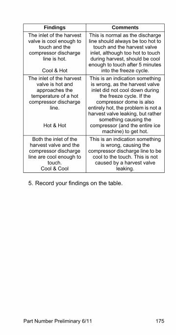
Part Number Preliminary 6/11 175
5. Record your findings on the table.
Findings Comments
The inlet of the harvest valve is cool enough to
touch and the compressor discharge
line is hot.
Cool & Hot
This is normal as the discharge line should always be too hot to
touch and the harvest valve inlet, although too hot to touch during harvest, should be cool
enough to touch after 5 minutes into the freeze cycle.
The inlet of the harvest valve is hot and approaches the
temperature of a hot compressor discharge
line.
Hot & Hot
This is an indication something is wrong, as the harvest valve inlet did not cool down during
the freeze cycle. If the compressor dome is also
entirely hot, the problem is not a harvest valve leaking, but rather
something causing the compressor (and the entire ice
machine) to get hot.
Both the inlet of the harvest valve and the compressor discharge line are cool enough to
touch.Cool & Cool
This is an indication something is wrong, causing the
compressor discharge line to be cool to the touch. This is not caused by a harvest valve
leaking.
176 Part Number Preliminary 6/11
Discharge Line Temperature AnalysisGENERAL
Knowing if the discharge line temperature is increasing, decreasing or remaining constant can be an important diagnostic tool. Compressor discharge line temperature on a normally operating ice machine steadily increases throughout the freeze cycle.
Ambient air temperatures affect the discharge line temperature.
Higher ambient air temperatures at the condenser and/or higher inlet water temperature = higher discharge line temperatures at the compressor.
Lower ambient air temperatures at the condenser and/or lower supply water temperature= lower discharge line temperatures at the compressor.
Regardless of ambient and water temperatures, the freeze cycle discharge line temperature will be higher than 150°F (66°C) [I0850/I1000 Air & Water Machines Only - 140°F (60°C)] at the end of the freeze cycle.
PROCEDURE
Connect a temperature probe on the compressor discharge line with-in 6" of the compressor and insulate.
Observe the discharge line temperature for the last three minutes of the freeze cycle and record on the table.
Discharge Line Temperature Above 150°F (66°C) [I0850/I1000 Air & Water Machines Only - 140°F (60°C)] At End Of Freeze Cycle:
Ice machines that are operating normally will have consistent minimum discharge line temperature of 150°F (66°C) [I0850/I1000 Air & Water Machines Only - 140°F (60°C)].
Part Number Preliminary 6/11 177
Water Regulating Valve
Problem (Freeze Cycle)
Valve not maintaining discharge pressure.
• Valve incorrectly set, dirty or defective. Adjust valve to correct discharge pressure for your model (refer to cycle times/24 hour productions charts), clean or replace valve.
Discharge pressure extremely high; Liquid line entering receiver feels hot.
• Water regulating valve incorrectly set or not opening. Verify Head Pressure Control Valve operation before changing water regulating valve.
Discharge pressure low, Liquid line entering receiver feels warm to hot.
• Ice machine low on charge. Verify Total System Refrigerant Charge page 301.
178 Part Number Preliminary 6/11
Final Analysis - Self-contained Air, Water & Remote Condenser Models
The column with the highest number of Checkmarks identifies the refrigeration problem.
COLUMN 1 - HARVEST VALVE LEAKING
Replace the valve as required.
COLUMN 2 - LOW CHARGE/TXV STARVING
Normally, a starving expansion valve only affects the freeze cycle pressures, not the harvest cycle pressures. A low refrigerant charge normally affects both pressures. Verify the ice machine is not low on charge before replacing an expansion valve.
1. Add refrigerant charge to verify a low charge (air and water self-contained only). Do not add more than 30% of nameplate refrigerant charge. If the problem is corrected, the ice machine is low on charge. *Do not add charge to remote models. The symptoms of a remote low on charge will result in a safety limit #1 in cool ambient temperatures. Check the liquid line temperature at the ice machine. The liquid line will be hot with a normal or below normal head pressure in freeze when the ice machine is low on refrigerant.
2. Find the refrigerant leak. The ice machine must operate with the nameplate charge. If the leak cannot be found, proper refrigerant procedures must still be followed Change the liquid line drier. Then, evacuate and weigh in the proper charge.
3. If the problem is not corrected by adding charge, the expansion valve is faulty.
Part Number Preliminary 6/11 179
COLUMN 3 - TXV FLOODING OR REFRIGERANT OVERCHARGE
A loose or improperly mounted expansion valve bulb causes the expansion valve to flood. Check bulb mounting, insulation, etc., before changing the valve. Verify refrigerant amount is correct by weighing recovered refrigerant before replacing a TXV. On Quad evaporator machines, the service technician is able to tell which TXV is flooding by comparing the evaporator outlets. Change only the flooding expansion valve. On dual expansion valve machines a third and fourth valve are not available for comparison and both valves will need to be changed.
COLUMN 4 - COMPRESSOR
Replace the compressor. To receive warranty credit, the compressor ports must be properly sealed by crimping and soldering them closed.
COLUMN 5 - HARVEST PRESSURE VALVE LEAKING (4 EVAPORATOR MODELS ONLY)
Replace the valve as required.
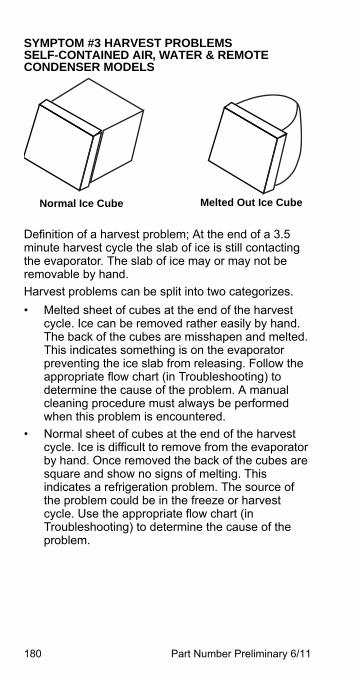
180 Part Number Preliminary 6/11
SYMPTOM #3 HARVEST PROBLEMS SELF-CONTAINED AIR, WATER & REMOTE CONDENSER MODELS
Definition of a harvest problem; At the end of a 3.5 minute harvest cycle the slab of ice is still contacting the evaporator. The slab of ice may or may not be removable by hand.
Harvest problems can be split into two categorizes.
• Melted sheet of cubes at the end of the harvest cycle. Ice can be removed rather easily by hand. The back of the cubes are misshapen and melted. This indicates something is on the evaporator preventing the ice slab from releasing. Follow the appropriate flow chart (in Troubleshooting) to determine the cause of the problem. A manual cleaning procedure must always be performed when this problem is encountered.
• Normal sheet of cubes at the end of the harvest cycle. Ice is difficult to remove from the evaporator by hand. Once removed the back of the cubes are square and show no signs of melting. This indicates a refrigeration problem. The source of the problem could be in the freeze or harvest cycle. Use the appropriate flow chart (in Troubleshooting) to determine the cause of the problem.
Normal Ice Cube Melted Out Ice Cube
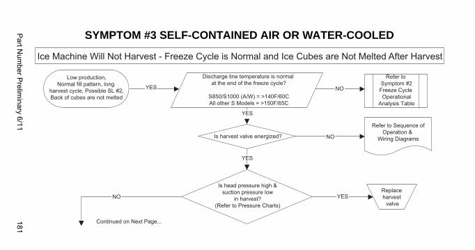
Part N
umber P
relimin
ary 6/11181
SYMPTOM #3 SELF-CONTAINED AIR OR WATER-COOLED
YES
YES
YES
NO
NO
NO YES
Ice Machine Will Not Harvest - Freeze Cycle is Normal and Ice Cubes are Not Melted After Harvest
Low production,Normal fill pattern, long
harvest cycle, Possible SL #2,Back of cubes are not melted
Discharge line temperature is normal at the end of the freeze cycle?
S850/S1000 (A/W) = >140F/60CAll other S Models = >150F/65C
Refer to Symptom #2Freeze Cycle Operational
Analysis Table
Is harvest valve energized?
Refer to Sequence ofOperation &
Wiring Diagrams
Is head pressure high &suction pressure low
in harvest?(Refer to Pressure Charts)
Replace harvest
valve
Continued on Next Page...
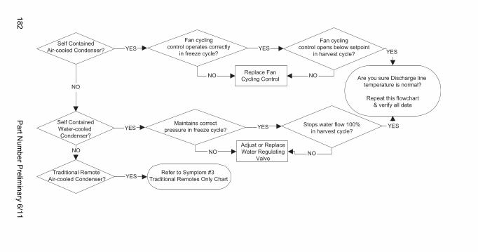
182P
art Num
ber Prelim
inary 6/11
YES YESYES
YES
YES
YES YES
NO NO
NO NO NO
NO
Self ContainedAir-cooled Condenser?
Self ContainedWater-cooled Condenser?
Fan cyclingcontrol operates correctly
in freeze cycle?
Fan cyclingcontrol opens below setpoint
in harvest cycle?
Replace Fan Cycling Control
Maintains correctpressure in freeze cycle?
Stops water flow 100%in harvest cycle?
Adjust or ReplaceWater Regulating
Valve
Traditional Remote Air-cooled Condenser?
Are you sure Discharge line temperature is normal?
Repeat this flowchart& verify all data
Refer to Symptom #3 Traditional Remotes Only Chart
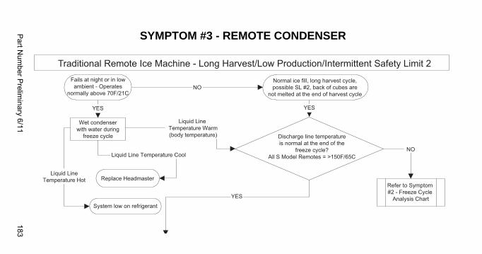
Part N
umber P
relimin
ary 6/11183
SYMPTOM #3 - REMOTE CONDENSER
Refer to Symptom #2 - Freeze Cycle
Analysis Chart
Traditional Remote Ice Machine - Long Harvest/Low Production/Intermittent Safety Limit 2Fails at night or in lowambient - Operates
normally above 70F/21C
YES YES
YES
NOLiquid Line Temperature Cool
NO
Liquid LineTemperature Hot
Liquid Line Temperature Warm(body temperature)
Wet condenserwith water during
freeze cycle
Replace Headmaster
System low on refrigerant
Normal ice fill, long harvest cycle,possible SL #2, back of cubes are
not melted at the end of harvest cycle
Discharge line temperatureis normal at the end of the
freeze cycle?All S Model Remotes = >150F/65C
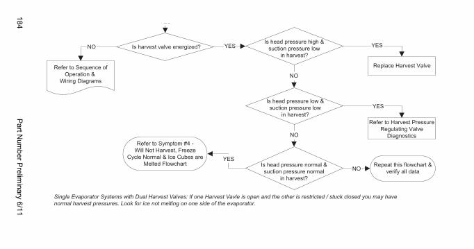
184P
art Num
ber Prelim
inary 6/11
Refer to Sequence ofOperation &
Wiring Diagrams
YES
YES
YES
NO
NO
NO YES
NO
YES
Is harvest valve energized?Is head pressure high &
suction pressure lowin harvest?
Replace Harvest Valve
Is head pressure low &suction pressure low
in harvest?
Is head pressure normal &suction pressure normal
in harvest?
Refer to Harvest PressureRegulating Valve
Diagnostics
Repeat this flowchart &verify all data
Refer to Symptom #4 -Will Not Harvest, Freeze
Cycle Normal & Ice Cubes areMelted Flowchart
Single Evaporator Systems with Dual Harvest Valves: If one Harvest Vavle is open and the other is restricted / stuck closed you may have normal harvest pressures. Look for ice not melting on one side of the evaporator.
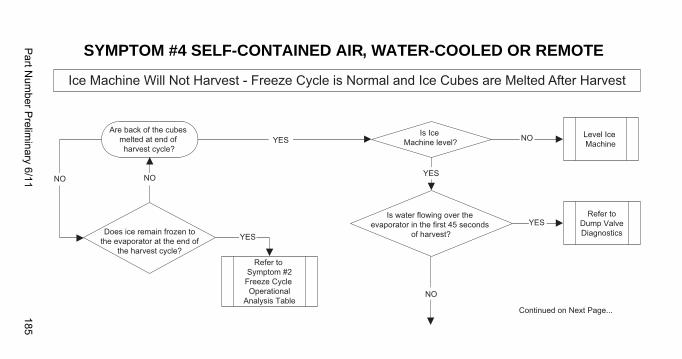
Part N
umber P
relimin
ary 6/11185
SYMPTOM #4 SELF-CONTAINED AIR, WATER-COOLED OR REMOTE
Level Ice Machine
Refer toDump ValveDiagnostics
Is water flowing over the evaporator in the first 45 seconds
of harvest?
Is Ice Machine level?
Are back of the cubes melted at end of harvest cycle?
Does ice remain frozen tothe evaporator at the end of
the harvest cycle?
YES
YES
YES
YES
NO
NO
NONO
Ice Machine Will Not Harvest - Freeze Cycle is Normal and Ice Cubes are Melted After Harvest
Continued on Next Page...
Refer to Symptom #2Freeze Cycle Operational
Analysis Table
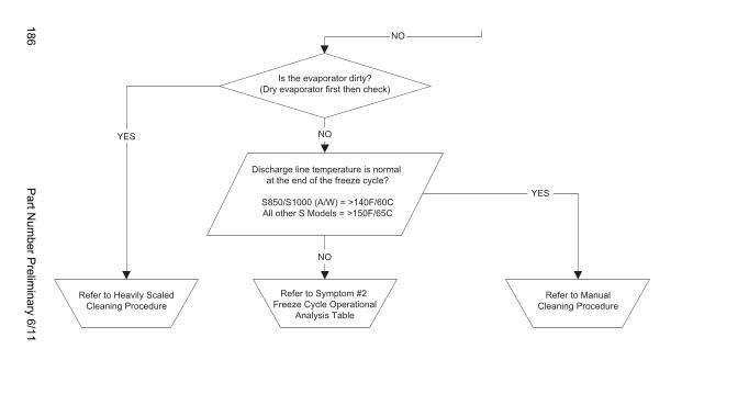
186P
art Num
ber Prelim
inary 6/11
Refer to Symptom #2 Freeze Cycle Operational
Analysis Table
Refer to Heavily ScaledCleaning Procedure
Discharge line temperature is normal at the end of the freeze cycle?
S850/S1000 (A/W) = >140F/60CAll other S Models = >150F/65C
Refer to ManualCleaning Procedure
Is the evaporator dirty?(Dry evaporator first then check)
YES
YES
NO
NO
NO

Part Number Preliminary 6/11 187
This Page Intentionally Left Blank

188 Part Number Preliminary 6/11
This Page Intentionally Left Blank
Part Number Preliminary 6/11 189
Symptom #2 - QuietQube® Remote Condensing Unit Models
SYMPTOM #2 LOW PRODUCTION, LONG FREEZEIce Machine has a Long Freeze Cycle.
Ice Formation is Thick or Thin on Top or Bottom of Evaporator or Low Production
How to Use the Freeze Cycle Refrigeration System Operational Analysis Table
GENERAL
These tables must be used with charts, checklists and other references to eliminate refrigeration components not listed on the tables and external items and problems which can cause good refrigeration components to appear defective.
The tables list five different defects that may affect the ice machine’s operation.
NOTE: A low-on-charge ice machine and a starving expansion valve have very similar characteristics and are listed under the same column.
NOTE: Before starting, see “Before Beginning Service” for a few questions to ask when talking to the ice machine owner.
190 Part Number Preliminary 6/11
PROCEDURE
Step 1 Complete the “Operation Analysis” column.
Read down the left “Operational Analysis” column. Perform all procedures and check all information listed. Each item in this column has supporting reference material to help analyze each step.
While analyzing each item separately, you may find an “external problem” causing a good refrigerant component to appear bad. Correct problems as they are found. If the operational problem is found, it is not necessary to complete the remaining procedures.
Step 2 Enter Checkmarks ().
Each time the actual findings of an item in the “Operational Analysis” column matches the published findings on the table, enter a Checkmark.
Example: Freeze cycle suction pressure is determined to be low. Enter a Checkmark in the “low” column.
Step 3 Add the Checkmarks listed under each of the four columns. Note the column number with the highest total and proceed to “Final Analysis.”
NOTE: If two columns have matching high numbers, a procedure was not performed properly, supporting material was not analyzed correctly or the problem component is not covered by the analysis table.
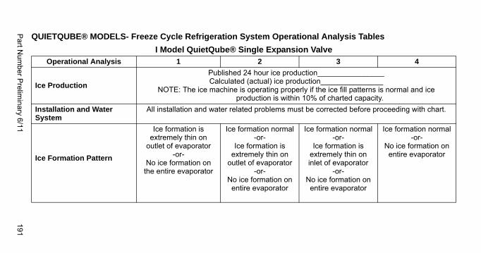
Part N
umber P
relimin
ary 6/11191
QUIETQUBE® MODELS- Freeze Cycle Refrigeration System Operational Analysis Tables
I Model QuietQube® Single Expansion ValveOperational Analysis 1 2 3 4
Ice Production
Published 24 hour ice production________________Calculated (actual) ice production_______________
NOTE: The ice machine is operating properly if the ice fill patterns is normal and ice production is within 10% of charted capacity.
Installation and Water System
All installation and water related problems must be corrected before proceeding with chart.
Ice Formation Pattern
Ice formation is extremely thin on
outlet of evaporator-or-
No ice formation on the entire evaporator
Ice formation normal-or-
Ice formation is extremely thin on
outlet of evaporator-or-
No ice formation on entire evaporator
Ice formation normal-or-
Ice formation is extremely thin on inlet of evaporator
-or-No ice formation on
entire evaporator
Ice formation normal-or-
No ice formation on entire evaporator
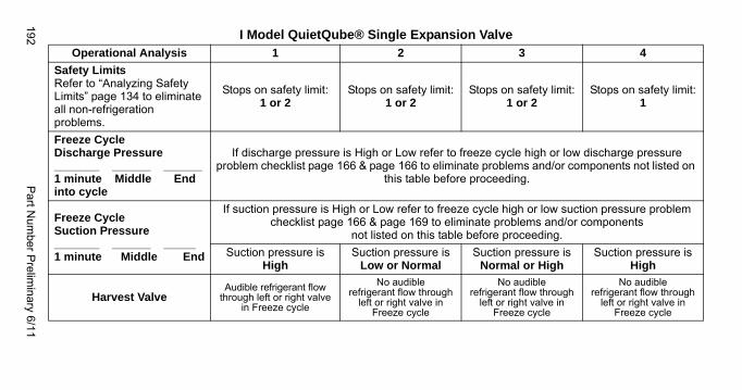
192P
art Num
ber Prelim
inary 6/11
Safety LimitsRefer to “Analyzing Safety Limits” page 134 to eliminate all non-refrigeration problems.
Stops on safety limit:1 or 2
Stops on safety limit:1 or 2
Stops on safety limit:1 or 2
Stops on safety limit:1
Freeze Cycle Discharge Pressure_______ ______ ______1 minute Middle Endinto cycle
If discharge pressure is High or Low refer to freeze cycle high or low discharge pressure problem checklist page 166 & page 166 to eliminate problems and/or components not listed on
this table before proceeding.
Freeze Cycle Suction Pressure_______ ______ _____1 minute Middle End
If suction pressure is High or Low refer to freeze cycle high or low suction pressure problem checklist page 166 & page 169 to eliminate problems and/or components
not listed on this table before proceeding.
Suction pressure is High
Suction pressure is Low or Normal
Suction pressure is Normal or High
Suction pressure is High
Harvest ValveAudible refrigerant flow
through left or right valve in Freeze cycle
No audible refrigerant flow through
left or right valve in Freeze cycle
No audible refrigerant flow through
left or right valve in Freeze cycle
No audible refrigerant flow through
left or right valve in Freeze cycle
I Model QuietQube® Single Expansion ValveOperational Analysis 1 2 3 4
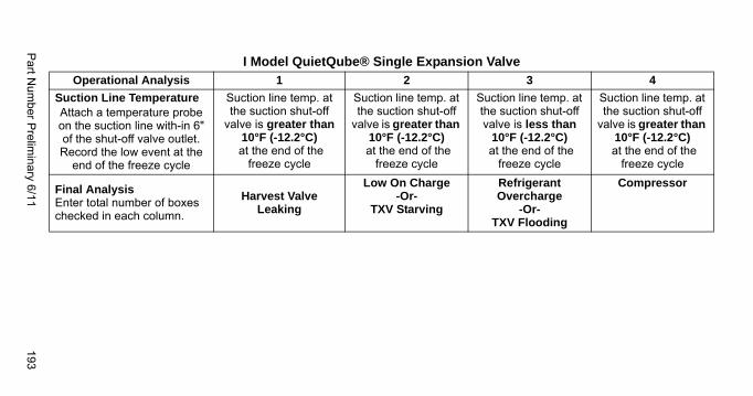
Part N
umber P
relimin
ary 6/11193
Suction Line TemperatureAttach a temperature probe on the suction line with-in 6" of the shut-off valve outlet. Record the low event at the
end of the freeze cycle
Suction line temp. at the suction shut-off
valve is greater than 10°F (-12.2°C)
at the end of the freeze cycle
Suction line temp. at the suction shut-off
valve is greater than 10°F (-12.2°C)
at the end of the freeze cycle
Suction line temp. at the suction shut-off valve is less than
10°F (-12.2°C) at the end of the
freeze cycle
Suction line temp. at the suction shut-off
valve is greater than 10°F (-12.2°C)
at the end of the freeze cycle
Final AnalysisEnter total number of boxes checked in each column.
Harvest ValveLeaking
Low On Charge-Or-
TXV Starving
Refrigerant Overcharge
-Or-TXV Flooding
Compressor
I Model QuietQube® Single Expansion ValveOperational Analysis 1 2 3 4
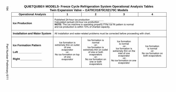
194P
art Num
ber Prelim
inary 6/11
QUIETQUBE® MODELS- Freeze Cycle Refrigeration System Operational Analysis TablesTwin Expansion Valve – I1470C/I1870C/I2170C Models
Operational Analysis 1 2 3 4
Ice ProductionPublished 24-hour ice production __________Calculated (actual) 24-hour ice production __________NOTE: The ice machine is operating properly if the ice fill pattern is normaland ice production is within 10% of charted capacity.
Installation and Water System All installation and water-related problems must be corrected before proceeding with chart.
Ice Formation Pattern
Left _______________
Right ______________
Ice formation is extremely thin on outlet
of one evaporator
-or-No ice formation on top
of one evaporator
Ice formation is normal
-or-Ice formation is
extremely thin on outlet of one or both evaporators
-or-No ice formation on
one or both evaporators
Ice formation is normal
-or-Ice formation is
extremely thin on the inlet of one evaporator
-or-No ice formation on one
evaporator
Ice formation is normal
-or-No ice formation on
both evaporators
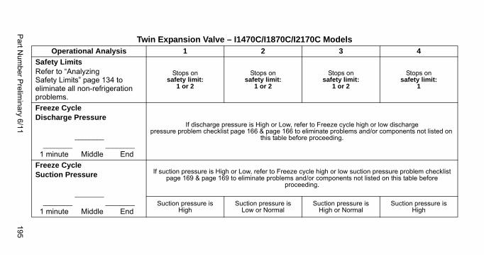
Part N
umber P
relimin
ary 6/11195
Safety LimitsRefer to “Analyzing Safety Limits” page 134 to eliminate all non-refrigeration problems.
Stops on safety limit:
1 or 2
Stops on safety limit:
1 or 2
Stops on safety limit:
1 or 2
Stops on safety limit:
1
Freeze Cycle Discharge Pressure
________ ________ ________
1 minute Middle End
If discharge pressure is High or Low, refer to Freeze cycle high or low discharge pressure problem checklist page 166 & page 166 to eliminate problems and/or components not listed on
this table before proceeding.
Freeze Cycle Suction Pressure
________ ________ ________
1 minute Middle End
If suction pressure is High or Low, refer to Freeze cycle high or low suction pressure problem checklist page 169 & page 169 to eliminate problems and/or components not listed on this table before
proceeding.
Suction pressure isHigh
Suction pressure isLow or Normal
Suction pressure isHigh or Normal
Suction pressure isHigh
Twin Expansion Valve – I1470C/I1870C/I2170C ModelsOperational Analysis 1 2 3 4
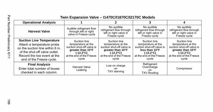
Part N
umber P
relimin
ary 6/11196
Harvest ValveAudible refrigerant flow
through left or right valve in Freeze cycle
No audible refrigerant flow through
left or right valve in Freeze cycle
No audible refrigerant flow through
left or right valve in Freeze cycle
No audible refrigerant flow through
left or right valve in Freeze cycle
Suction Line TemperatureAttach a temperature probe
on the suction line within 6 in. of the shut-off valve outlet. Record the low event at the
end of the Freeze cycle.
Suction line temperature at the
suction shut-off valve is greater than 10°F
(-12.2°C)at the end of the Freeze
cycle
Suction line temperature at the
suction shut-off valve is greater than 10°F
(-12.2°C)at the end of the Freeze
cycle
Suction line temperature at the
suction shut-off valve is less than 10°F
(-12.2°C)at the end of the Freeze
cycle
Suction line temperature at the
suction shut-off valve is greater than 10°F
(-12.2°C)at the end of the Freeze
cycle
Final AnalysisEnter total number of boxes
checked in each column.
Harvest Valve Leaking
Low on charge-or-
TXV starving
RefrigerantOvercharge
-or-TXV flooding
Compressor
Twin Expansion Valve – I1470C/I1870C/I2170C ModelsOperational Analysis 1 2 3 4
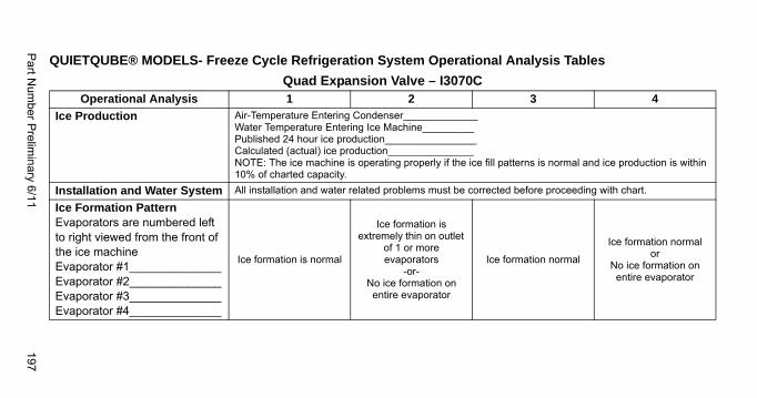
Part N
umber P
relimin
ary 6/11197
QUIETQUBE® MODELS- Freeze Cycle Refrigeration System Operational Analysis Tables
Quad Expansion Valve – I3070COperational Analysis 1 2 3 4
Ice Production Air-Temperature Entering Condenser_____________Water Temperature Entering Ice Machine_________Published 24 hour ice production________________Calculated (actual) ice production_______________NOTE: The ice machine is operating properly if the ice fill patterns is normal and ice production is within 10% of charted capacity.
Installation and Water System All installation and water related problems must be corrected before proceeding with chart.
Ice Formation PatternEvaporators are numbered left to right viewed from the front of the ice machineEvaporator #1______________Evaporator #2______________Evaporator #3______________Evaporator #4______________
Ice formation is normal
Ice formation is extremely thin on outlet
of 1 or more evaporators
-or-No ice formation on entire evaporator
Ice formation normal
Ice formation normalor
No ice formation on entire evaporator
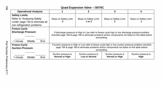
198P
art Num
ber Prelim
inary 6/11
Safety LimitsRefer to “Analyzing Safety Limits” page 134 to eliminate all non refrigeration problems
Stops on Safety Limit: 2
Stops on Safety Limit: 1 or 2
Stops on Safety Limit:2
Stops on Safety Limit: 1
Freeze Cycle Discharge Pressure
________ ________ ________
1 minute Middle End
If discharge pressure is High or Low refer to freeze cycle high or low discharge pressure problem checklist page 166 & page 166 to eliminate problems and/or components not listed on this table before
proceeding.
Freeze Cycle Suction Pressure
________ ________ ________
1 minute Middle End
If suction pressure is High or Low refer to freeze cycle high or low suction pressure problem checklist page 169 & page 169 to eliminate problems and/or components not listed on this table before
proceeding.
Suction pressure is Normal or High
Suction pressure isLow or Normal
Suction pressure isNormal or High
Suction pressure is High
Quad Expansion Valve – I3070COperational Analysis 1 2 3 4
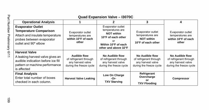
Part N
umber P
relimin
ary 6/11199
Evaporator Outlet Temperature ComparisonAttach and insulate temperature probes between evaporator outlet and 90° elbow
Evaporator outlet temperatures are
within 10°F of each other
Evaporator outlet temperatures are
NOT within 10°F of each other
orWithin 10°F of each
other and above 32°F
Evaporator outlet temperatures are
NOT within 10°F of each other
Evaporator outlet temperatures are
within 10°F of each other
Harvest ValveA leaking harvest valve gives an audible indication before ice fill pattern or machine performance is affected
Audible flow of refrigerant through
any harvest valve during the freeze cycle
No Audible flow of refrigerant through
any harvest valve during the freeze cycle
No Audible flow of refrigerant through
any harvest valve during the freeze cycle
No Audible flow of refrigerant through
any harvest valve during the freeze cycle
Final AnalysisEnter total number of boxes checked in each column.
Harvest Valve LeakingLow On Charge
-Or-TXV Starving
Refrigerant Overcharge
orTXV Flooding
Compressor
Quad Expansion Valve – I3070COperational Analysis 1 2 3 4
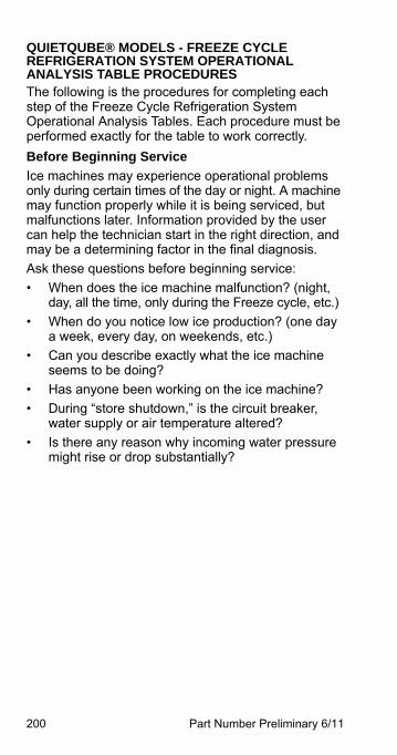
200 Part Number Preliminary 6/11
QUIETQUBE® MODELS - FREEZE CYCLE REFRIGERATION SYSTEM OPERATIONAL ANALYSIS TABLE PROCEDURESThe following is the procedures for completing each step of the Freeze Cycle Refrigeration System Operational Analysis Tables. Each procedure must be performed exactly for the table to work correctly.
Before Beginning Service
Ice machines may experience operational problems only during certain times of the day or night. A machine may function properly while it is being serviced, but malfunctions later. Information provided by the user can help the technician start in the right direction, and may be a determining factor in the final diagnosis.
Ask these questions before beginning service:
• When does the ice machine malfunction? (night, day, all the time, only during the Freeze cycle, etc.)
• When do you notice low ice production? (one day a week, every day, on weekends, etc.)
• Can you describe exactly what the ice machine seems to be doing?
• Has anyone been working on the ice machine?
• During “store shutdown,” is the circuit breaker, water supply or air temperature altered?
• Is there any reason why incoming water pressure might rise or drop substantially?
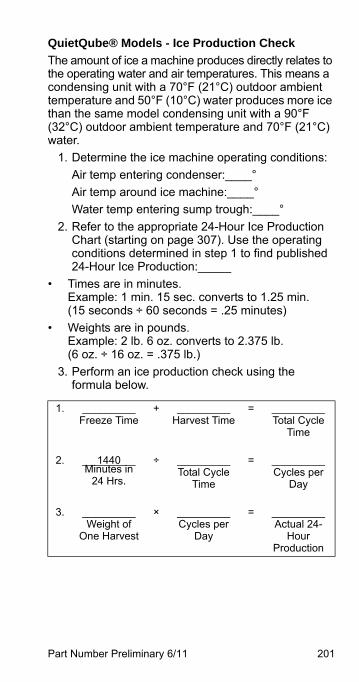
Part Number Preliminary 6/11 201
QuietQube® Models - Ice Production Check
The amount of ice a machine produces directly relates to the operating water and air temperatures. This means a condensing unit with a 70°F (21°C) outdoor ambient temperature and 50°F (10°C) water produces more ice than the same model condensing unit with a 90°F (32°C) outdoor ambient temperature and 70°F (21°C) water.
1. Determine the ice machine operating conditions:
Air temp entering condenser:____°
Air temp around ice machine:____°
Water temp entering sump trough:____°
2. Refer to the appropriate 24-Hour Ice Production Chart (starting on page 307). Use the operating conditions determined in step 1 to find published 24-Hour Ice Production:_____
• Times are in minutes.Example: 1 min. 15 sec. converts to 1.25 min.(15 seconds ÷ 60 seconds = .25 minutes)
• Weights are in pounds.Example: 2 lb. 6 oz. converts to 2.375 lb.(6 oz. ÷ 16 oz. = .375 lb.)
3. Perform an ice production check using the formula below.
1. _________Freeze Time
+ _________Harvest Time
= _________Total Cycle
Time
2. 1440_________Minutes in
24 Hrs.
÷ _________Total Cycle
Time
= _________Cycles per
Day
3. _________Weight of
One Harvest
× _________Cycles per
Day
= _________Actual 24-
HourProduction
202 Part Number Preliminary 6/11
Weighing the ice is the only 100% accurate check. However, if the ice pattern is normal and the 1/8 in. thickness is maintained, the ice slab weights listed with the 24-Hour Ice Production Charts may be used.
4. Compare the results of step 3 with step 2. Ice production checks that are within 10% of the chart are considered normal. If they match closely, determine if:
• Another ice machine is required.
• More storage capacity is required.
• Relocating the existing equipment to lower the load conditions is required.
Contact the local Manitowoc Distributor for information on available options and accessories.
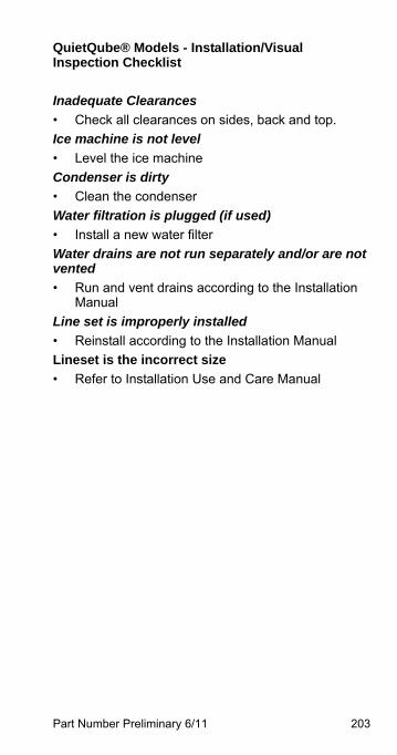
Part Number Preliminary 6/11 203
QuietQube® Models - Installation/Visual Inspection Checklist
Inadequate Clearances
• Check all clearances on sides, back and top.
Ice machine is not level
• Level the ice machine
Condenser is dirty
• Clean the condenser
Water filtration is plugged (if used)
• Install a new water filter
Water drains are not run separately and/or are not vented
• Run and vent drains according to the Installation Manual
Line set is improperly installed
• Reinstall according to the Installation Manual
Lineset is the incorrect size
• Refer to Installation Use and Care Manual
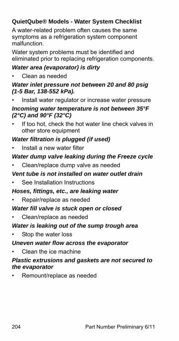
204 Part Number Preliminary 6/11
QuietQube® Models - Water System Checklist
A water-related problem often causes the same symptoms as a refrigeration system component malfunction.
Water system problems must be identified and eliminated prior to replacing refrigeration components.
Water area (evaporator) is dirty
• Clean as needed
Water inlet pressure not between 20 and 80 psig (1-5 Bar, 138-552 kPa).
• Install water regulator or increase water pressure
Incoming water temperature is not between 35°F (2°C) and 90°F (32°C)
• If too hot, check the hot water line check valves in other store equipment
Water filtration is plugged (if used)
• Install a new water filter
Water dump valve leaking during the Freeze cycle
• Clean/replace dump valve as needed
Vent tube is not installed on water outlet drain
• See Installation Instructions
Hoses, fittings, etc., are leaking water
• Repair/replace as needed
Water fill valve is stuck open or closed
• Clean/replace as needed
Water is leaking out of the sump trough area
• Stop the water loss
Uneven water flow across the evaporator
• Clean the ice machine
Plastic extrusions and gaskets are not secured to the evaporator
• Remount/replace as needed
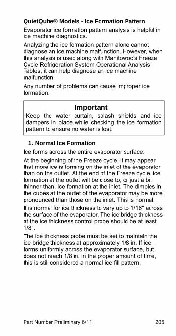
Part Number Preliminary 6/11 205
QuietQube® Models - Ice Formation Pattern
Evaporator ice formation pattern analysis is helpful in ice machine diagnostics.
Analyzing the ice formation pattern alone cannot diagnose an ice machine malfunction. However, when this analysis is used along with Manitowoc’s Freeze Cycle Refrigeration System Operational Analysis Tables, it can help diagnose an ice machine malfunction.
Any number of problems can cause improper ice formation.
1. Normal Ice Formation
Ice forms across the entire evaporator surface.
At the beginning of the Freeze cycle, it may appear that more ice is forming on the inlet of the evaporator than on the outlet. At the end of the Freeze cycle, ice formation at the outlet will be close to, or just a bit thinner than, ice formation at the inlet. The dimples in the cubes at the outlet of the evaporator may be more pronounced than those on the inlet. This is normal.
It is normal for ice thickness to vary up to 1/16" across the surface of the evaporator. The ice bridge thickness at the ice thickness control probe should be at least1/8".
The ice thickness probe must be set to maintain the ice bridge thickness at approximately 1/8 in. If ice forms uniformly across the evaporator surface, but does not reach 1/8 in. in the proper amount of time, this is still considered a normal ice fill pattern.
ImportantKeep the water curtain, splash shields and icedampers in place while checking the ice formationpattern to ensure no water is lost.
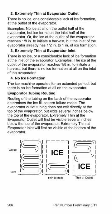
206 Part Number Preliminary 6/11
2. Extremely Thin at Evaporator Outlet
There is no ice, or a considerable lack of ice formation, at the outlet of the evaporator.
Examples: No ice at all on the outlet half of the evaporator, but ice forms on the inlet half of the evaporator. Or, the ice at the outlet of the evaporator reaches 1/8 in. to initiate a harvest, but the inlet of the evaporator already has 1/2 in. to 1 in. of ice formation.
3. Extremely Thin at Evaporator Inlet
There is no ice, or a considerable lack of ice formation at the inlet of the evaporator. Examples: The ice at the outlet of the evaporator reaches 1/8 in. to initiate a harvest, but there is no ice formation at all on the inlet of the evaporator.
4. No Ice Formation
The ice machine operates for an extended period, but there is no ice formation at all on the evaporator.
Evaporator Tubing Routing
Routing of the tubing on the back of the evaporator determines the ice fill pattern failure mode. The evaporator outlet tubing does not exit directly at the top of the evaporator, but exits several inches below the top of the evaporator. Extremely Thin at the Evaporator Outlet will first be visible several inches below the top of the evaporator. Extremely Thin at Evaporator Inlet will first be visible at the bottom of the evaporator.
Outlet
Inlet
Thin at OutletThin at Inlet
ICE
ICE
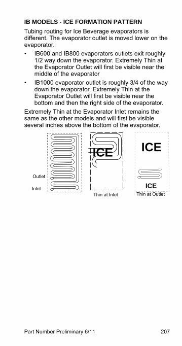
Part Number Preliminary 6/11 207
IB MODELS - ICE FORMATION PATTERN
Tubing routing for Ice Beverage evaporators is different. The evaporator outlet is moved lower on the evaporator.
• IB600 and IB800 evaporators outlets exit roughly 1/2 way down the evaporator. Extremely Thin at the Evaporator Outlet will first be visible near the middle of the evaporator
• IB1000 evaporator outlet is roughly 3/4 of the way down the evaporator. Extremely Thin at the Evaporator Outlet will first be visible near the bottom and then the right side of the evaporator.
Extremely Thin at the Evaporator Inlet remains the same as the other models and will first be visible several inches above the bottom of the evaporator.
ICE
Thin at Inlet Thin at OutletInlet
Outlet
ICE
ICE
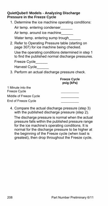
208 Part Number Preliminary 6/11
QuietQube® Models - Analyzing Discharge Pressure in the Freeze Cycle
1. Determine the ice machine operating conditions:
Air temp. entering condenser______
Air temp. around ice machine______
Water temp. entering sump trough______
2. Refer to Operating Pressure table (starting on page 307) for ice machine being checked.
Use the operating conditions determined in step 1 to find the published normal discharge pressures.
Freeze Cycle______
Harvest Cycle______
3. Perform an actual discharge pressure check.
4. Compare the actual discharge pressure (step 3) with the published discharge pressure (step 2).
The discharge pressure is normal when the actual pressure falls within the published pressure range for the ice machine’s operating conditions. It is normal for the discharge pressure to be higher at the beginning of the Freeze cycle (when load is greatest), then drop throughout the Freeze cycle.
Freeze Cyclepsig (kPa)
1 Minute into theFreeze Cycle __________
Middle of Freeze Cycle __________
End of Freeze Cycle __________

Part Number Preliminary 6/11 209
QUIETQUBE® MODELS - FREEZE CYCLE DISCHARGE PRESSURE HIGH CHECKLIST
Improper Installation
• Refer to “Installation/Visual Inspection Checklist” (page 162)
Air Condenser
• Dirty condenser filter
• Dirty condenser fins
• High inlet air temperature
• Condenser discharge air recirculation
• Defective fan cycling control (page 273)
• Defective fan motor
• Defective head pressure control valve {Remotes}
Water Condenser
• Low water pressure [20 psig (138 kPa) min.]
• High inlet water temperature (90°F/32°C max.)
• Dirty condenser
• Dirty/Defective water regulating valve
• Water regulating valve out of adjustment
Other
• Overcharged
• Non-condensable (air) in system
• Wrong type of refrigerant
• Non-Manitowoc components in system
• High side refrigerant lines/component restricted
210 Part Number Preliminary 6/11
QUIETQUBE® MODELS - FREEZE CYCLE DISCHARGE PRESSURE LOW CHECKLIST
Improper Installation
• Refer to “Installation/Visual Inspection Checklist” (page 162)
Air Cooled Condensers
• Defective head pressure control valve, won’t bypass(page 273)
• Defective fan cycle control, stuck closed (page 273)
Water Cooled Condensers
• Water Regulating Valve out of adjustment
• Water Regulating Valve Defective
Other
• Undercharged
• Wrong type of refrigerant
• Non-Manitowoc components in system
• Liquid line/component restricted
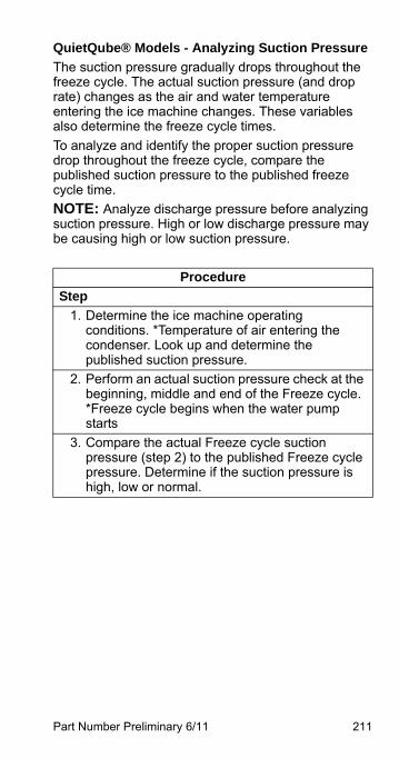
Part Number Preliminary 6/11 211
QuietQube® Models - Analyzing Suction Pressure
The suction pressure gradually drops throughout the freeze cycle. The actual suction pressure (and drop rate) changes as the air and water temperature entering the ice machine changes. These variables also determine the freeze cycle times.
To analyze and identify the proper suction pressure drop throughout the freeze cycle, compare the published suction pressure to the published freeze cycle time.
NOTE: Analyze discharge pressure before analyzing suction pressure. High or low discharge pressure may be causing high or low suction pressure.
Procedure
Step
1. Determine the ice machine operating conditions. *Temperature of air entering the condenser. Look up and determine the published suction pressure.
2. Perform an actual suction pressure check at the beginning, middle and end of the Freeze cycle. *Freeze cycle begins when the water pump starts
3. Compare the actual Freeze cycle suction pressure (step 2) to the published Freeze cycle pressure. Determine if the suction pressure is high, low or normal.
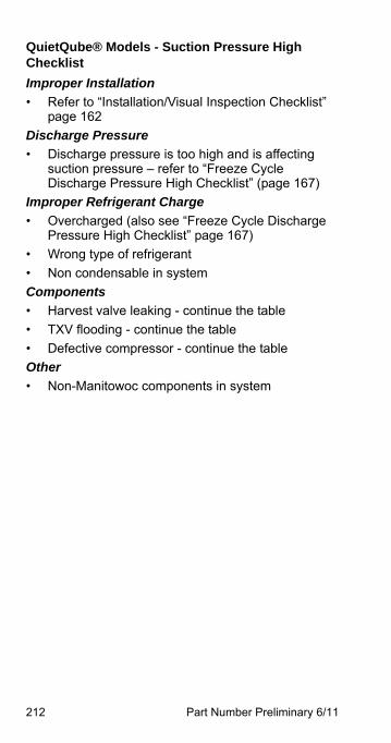
212 Part Number Preliminary 6/11
QuietQube® Models - Suction Pressure High Checklist
Improper Installation
• Refer to “Installation/Visual Inspection Checklist” page 162
Discharge Pressure
• Discharge pressure is too high and is affecting suction pressure – refer to “Freeze Cycle Discharge Pressure High Checklist” (page 167)
Improper Refrigerant Charge
• Overcharged (also see “Freeze Cycle Discharge Pressure High Checklist” page 167)
• Wrong type of refrigerant
• Non condensable in system
Components
• Harvest valve leaking - continue the table
• TXV flooding - continue the table
• Defective compressor - continue the table
Other
• Non-Manitowoc components in system
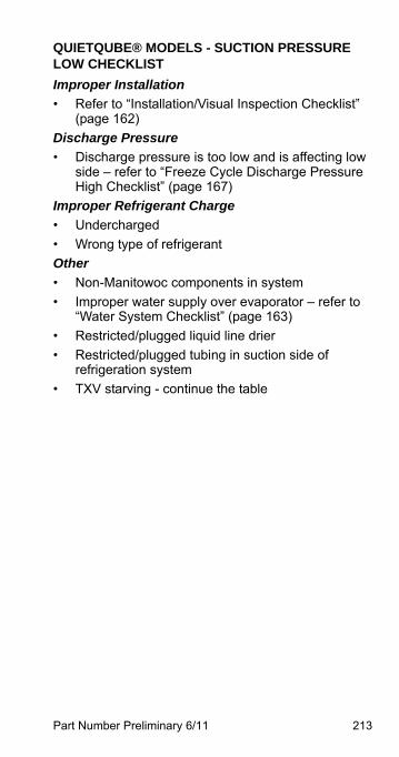
Part Number Preliminary 6/11 213
QUIETQUBE® MODELS - SUCTION PRESSURE LOW CHECKLIST
Improper Installation
• Refer to “Installation/Visual Inspection Checklist” (page 162)
Discharge Pressure
• Discharge pressure is too low and is affecting low side – refer to “Freeze Cycle Discharge Pressure High Checklist” (page 167)
Improper Refrigerant Charge
• Undercharged
• Wrong type of refrigerant
Other
• Non-Manitowoc components in system
• Improper water supply over evaporator – refer to “Water System Checklist” (page 163)
• Restricted/plugged liquid line drier
• Restricted/plugged tubing in suction side of refrigeration system
• TXV starving - continue the table
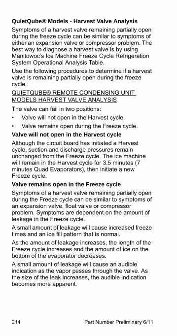
214 Part Number Preliminary 6/11
QuietQube® Models - Harvest Valve Analysis
Symptoms of a harvest valve remaining partially open during the freeze cycle can be similar to symptoms of either an expansion valve or compressor problem. The best way to diagnose a harvest valve is by using Manitowoc’s Ice Machine Freeze Cycle Refrigeration System Operational Analysis Table.
Use the following procedures to determine if a harvest valve is remaining partially open during the freeze cycle.
QUIETQUBE® REMOTE CONDENSING UNIT MODELS HARVEST VALVE ANALYSIS
The valve can fail in two positions:
• Valve will not open in the Harvest cycle.
• Valve remains open during the Freeze cycle.
Valve will not open in the Harvest cycle
Although the circuit board has initiated a Harvest cycle, suction and discharge pressures remain unchanged from the Freeze cycle. The ice machine will remain in the Harvest cycle for 3.5 minutes (7 minutes Quad Evaporators), then initiate a new Freeze cycle.
Valve remains open in the Freeze cycle
Symptoms of a harvest valve remaining partially open during the Freeze cycle can be similar to symptoms of an expansion valve, float valve or compressor problem. Symptoms are dependent on the amount of leakage in the Freeze cycle.
A small amount of leakage will cause increased freeze times and an ice fill pattern that is normal.
As the amount of leakage increases, the length of the Freeze cycle increases and the amount of ice on the bottom of the evaporator decreases.
A small amount of leakage will cause an audible indication as the vapor passes through the valve. As the size of the leak increases, the audible indication becomes more apparent.
Part Number Preliminary 6/11 215
QuietQube® Models - Analyzing Freeze Cycle Suction Line Temperature
Suction line temperature alone cannot diagnose an ice machine. However, comparing this temperature during the freeze cycle, along with using Manitowoc’s Symptom #2 - Refrigeration System Operational Analysis Table, can help diagnose an ice machine malfunction.
The actual temperature of the suction line varies by model, and will change throughout the freeze cycle. This makes documenting the “normal” suction line temperature difficult. The key to the diagnosis is observing the compressor suction line temperature during the last three minutes of the freeze cycle.
1. Use a quality temperature meter, capable of taking temperature readings on curved copper lines.
2. Attach the temperature meter thermocouple to the copper suction line within 6” of the shut-off valves.
3. Monitor the suction line temperature during the last three minutes of the freeze cycle and record the low event.
4. Use this with other information gathered on the Refrigeration Component Analysis Chart to determine the ice machine malfunction.
5. Verify refrigerant amount is correct by weight when recovering refrigerant and replacing a TXV. Grossly overcharged QuietQube® ice machine in ambient temperatures below 70°F will have a suction line temperature below 10°F.
ImportantDo not simply insert the sensing device under theinsulation. It must be attached to and reading theactual temperature of the copper line. Infaredthermometers are not recommended for thisprocedure.
216 Part Number Preliminary 6/11
QuietQube® Model Final Analysis
The column with the highest number of Checkmarks identifies the refrigeration problem.
COLUMN 1 - HARVEST VALVE LEAKING
Replace the valve as required.
COLUMN 2 - LOW CHARGE/TXV STARVING
Normally, a starving expansion valve only affects the freeze cycle pressures, not the harvest cycle pressures. A low refrigerant charge normally affects both pressures. Verify the ice machine is not low on charge before replacing an expansion valve.
1. Add refrigerant charge to verify a low charge (air and water self-contained only). Do not add more than 30% of nameplate refrigerant charge. If the problem is corrected, the ice machine is low on charge. *Do not add charge to remote models. The symptoms of a remote low on charge will result in a safety limit #1 in cool ambient temperatures. Check the liquid line temperature at the ice machine. The liquid line will be hot with a normal or below normal head pressure in freeze when the ice machine is low on refrigerant.
2. Find the refrigerant leak. The ice machine must operate with the nameplate charge. If the leak cannot be found, proper refrigerant procedures must still be followed Change the liquid line drier. Then, evacuate and weigh in the proper charge.
3. Verify refrigerant charge by weight when recovering to prevent misdiagnosis of the expansion valve.
Part Number Preliminary 6/11 217
COLUMN 3 - TXV FLOODING OR REFRIGERANT OVERCHARGE
A loose or improperly mounted expansion valve bulb causes the expansion valve to flood. Check bulb mounting, insulation, etc., before changing the valve. Verify refrigerant amount is correct by weighing recovered refrigerant before replacing a TXV. On Quad evaporator machines, the service technician is able to tell which TXV is flooding by comparing the evaporator outlets. Change only the flooding expansion valve. On dual expansion valve machines a third and fourth valve are not available for comparison and both valves will need to be changed.
COLUMN 4 - COMPRESSOR
Replace the compressor. To receive warranty credit, the compressor ports must be properly sealed by crimping and soldering them closed.
COLUMN 5 - HARVEST PRESSURE VALVE LEAKING (I3300W ONLY)
Replace the valve as required.
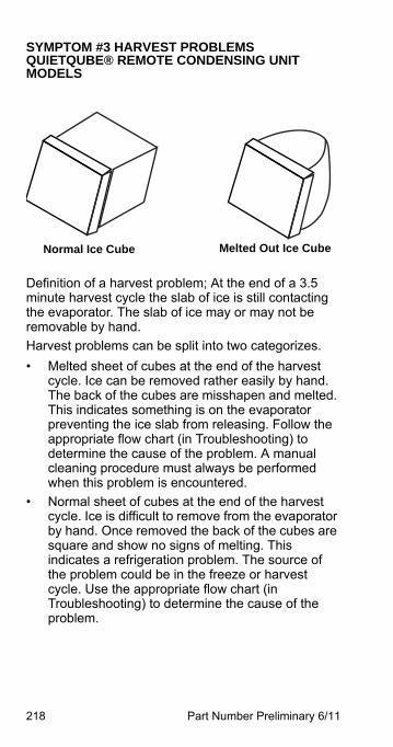
218 Part Number Preliminary 6/11
SYMPTOM #3 HARVEST PROBLEMS QUIETQUBE® REMOTE CONDENSING UNIT MODELS
Definition of a harvest problem; At the end of a 3.5 minute harvest cycle the slab of ice is still contacting the evaporator. The slab of ice may or may not be removable by hand.
Harvest problems can be split into two categorizes.
• Melted sheet of cubes at the end of the harvest cycle. Ice can be removed rather easily by hand. The back of the cubes are misshapen and melted. This indicates something is on the evaporator preventing the ice slab from releasing. Follow the appropriate flow chart (in Troubleshooting) to determine the cause of the problem. A manual cleaning procedure must always be performed when this problem is encountered.
• Normal sheet of cubes at the end of the harvest cycle. Ice is difficult to remove from the evaporator by hand. Once removed the back of the cubes are square and show no signs of melting. This indicates a refrigeration problem. The source of the problem could be in the freeze or harvest cycle. Use the appropriate flow chart (in Troubleshooting) to determine the cause of the problem.
Normal Ice Cube Melted Out Ice Cube
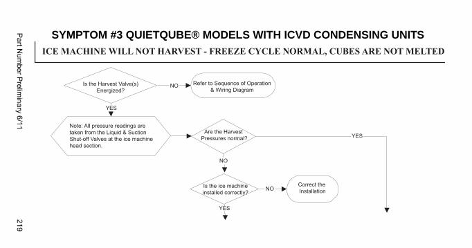
Part N
umber P
relimin
ary 6/11219
SYMPTOM #3 QUIETQUBE® MODELS WITH ICVD CONDENSING UNITS
Ice Machine Will Not Harvest - Freeze Cycle Is Normal and Ice Cubes Are Not Melted AfteIce Machine Will Not Harvest - Freeze Cycle Is Normal and Ice Cubes Are Not Melted After Harvest
Is the Harvest Valve(s)Energized?
Refer to Sequence of Operation& Wiring Diagram
Note: All pressure readings aretaken from the Liquid & SuctionShut-off Valves at the ice machinehead section.
Are the Harvest Pressures normal?
Is the ice machineinstalled correctly?
Correct the Installation
YES
YES
YES
NO
NO
NO
ICE MACHINE WILL NOT HARVEST - FREEZE CYCLE NORMAL, CUBES ARE NOT MELTED
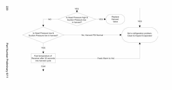
220P
art Num
ber Prelim
inary 6/11
NO
YES
YES
YESYES
No; Harvest PSI Normal
Feels Warm to Hot
Cold
Feel temperature of Receiver after 30 seconds
into harvest cycle
Is Head Pressure low &Suction Pressure low in harvest?
ReplaceHarvest
Valve
Is Head Pressure high &Suction Pressure low
in harvest?
Not a refrigeration problem,Clean & Inspect Evaporator
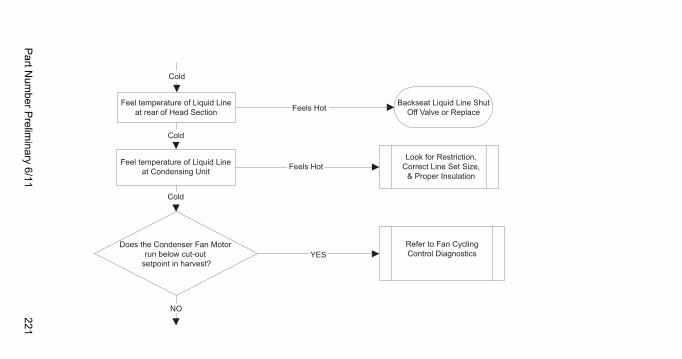
Part N
umber P
relimin
ary 6/11221
Feel temperature of Liquid Lineat rear of Head Section
Feel temperature of Liquid Lineat Condensing Unit
Does the Condenser Fan Motor run below cut-out
setpoint in harvest?
Backseat Liquid Line ShutOff Valve or Replace
Look for Restriction,Correct Line Set Size,
& Proper Insulation
Refer to Fan CyclingControl Diagnostics
Cold
Cold
Cold
Feels Hot
Feels Hot
YES
NO
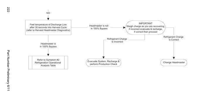
222P
art Num
ber Prelim
inary 6/11
Change Headmaster
NO
Feel temperature of Discharge Lineafter 30 seconds into Harvest Cycle
(refer to Harvest Headmaster Diagnostics)
Headmaster is not in 100% Bypass
Headmaster isin 100% Bypass
Refrigerant Charge is Incorrect
Evacuate System, Recharge &perform Production Check
Refer to Symptom #2Refrigeration Operational
Analysis Table
Refrigerant Charge is Correct
IMPORTANTWeigh charge as you are recovering,
if incorrect evacuate & recharge,if correct then proceed
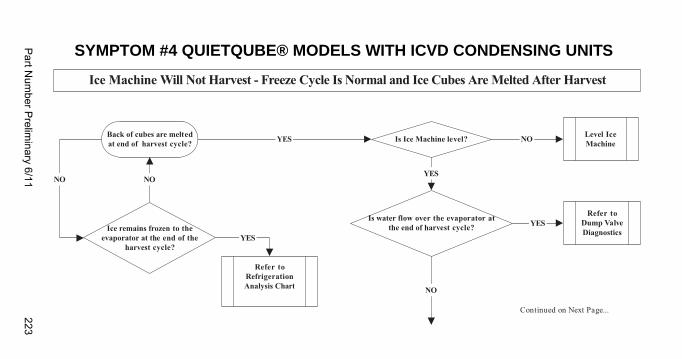
Part N
umber P
relimin
ary 6/11223
SYMPTOM #4 QUIETQUBE® MODELS WITH ICVD CONDENSING UNITS
Ice Machine Will Not Harvest - Freeze Cycle Is Normal and Ice Cubes Are Melted After Harvest
Is Ice Machine level?
NO NO
YES
YES
YES NO
Is water flow over the evaporator atthe end of harvest cycle? YES
NO
Refer toRefrigerationAnalysis Chart
Ice remains frozen to theevaporator at the end of the
harvest cycle?
Level IceMachine
Refer toDump ValveDiagnostics
Back of cubes are meltedat end of harvest cycle?
Continued on Next Page...
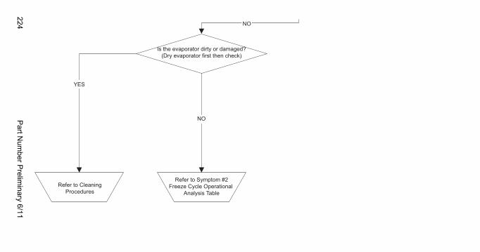
224P
art Num
ber Prelim
inary 6/11
Refer to Symptom #2Freeze Cycle Operational
Analysis TableRefer to Cleaning
Procedures
YES
NO
NO
Is the evaporator dirty or damaged?(Dry evaporator first then check)

Part Number Preliminary 6/11 225
This Page Intentionally Left Blank

226 Part Number Preliminary 6/11
This Page Intentionally Left Blank
Part Number Preliminary 6/11 227
Component Check Procedures
Electrical Components
CONTROL BOARD, DISPLAY BOARD AND TOUCH PADFUNCTION
The control board, display board and touch pad provide user input and control the ice machine sequence of operation.
NOTE: Anytime power is supplied to wires #55 & #56 on the control board, the “Display” and “Micro” lights will flash like a heartbeat. The two green lights are located on the top right corner of the control board.
Display Diagnostics
1. Micro light flashes and display light is off.
2. Disconnect and reconnect both ends of the communication cable running between the control board and the back of the display module.
3. Press the power button on the display and watch the green Display light on the control board.
A. Display light flashes- Test run ice machine.
B. Display light is off - Replace communication cable first as a test, then replace display/touch pad assembly if required.
228 Part Number Preliminary 6/11
Control Board Diagnostics
1. Micro light is not flashing a heartbeat.
2. Disconnect line voltage power supply to the ice machine and wait a minimum of 15 seconds, then reapply power.
A. Micro light flashes - continue with step 3.
B. Micro light is off - Replace control board.
3. Perform the following keystrokes on the display.
• Press Menu, scroll down to Service and press right arrow
• Scroll down to Diagnostics and press right arrow
• Display reads Control Board, press right arrow
• Display reads Self Check, press right arrow to start control board test
The control board performs a self test. As the test progresses the display will show Checkmarks at the top left of the display screen. When the fifth Checkmark appears the display will show “Status Passed” indicating the control board is functioning normally.

Part Number Preliminary 6/11 229
Touch Pad Diagnostics
Follow the control board diagnostics to the Status Passed display. Perform the following keystrokes on the display.
• Display reads Status Passed, press the right arrow
• Display reads Pass Yes, press the right arrow
• Display reads Key Pad Test, press the right arrow
4. Test the functionality of all buttons on the touch pad.
NOTE: Pushing the power button will start and stop the ice machine. Testing it last will allow the ice machine to continue running a freeze cycle.
• As you press the buttons the first letter of the corresponding word will flash indicating the push button is operating correctly
• Press the right arrow 5 times rapidly to exit.
5. Display reads Pass Yes and Pass No.
• Press left arrow 4 times to exit to home screen.
230 Part Number Preliminary 6/11
CONTROL BOARD RELAY TESTThe control board can be set to energize all relays for 3.5 minutes. This allows testing to verify control board relays are closed and line voltage is available for ice machine components - Water pump, dump valve, water inlet valve, harvest valve(s), air compressor, contactor/compressor/fan motor - The fan cycle control must close to energize the fan motor.
1. Press power button to turn off ice machine.
2. Perform the following keystrokes on the display.
• Press Menu, scroll down to Service and press the right arrow
• Scroll down to Diagnostics, press the right arrow and select Diagnostics
• Display reads Control Board, press right arrow
• Scroll down to enbl relays and press right arrow to start control board test
3. The control board will energize all relays and the red light next to the relay. The red light indicates the relay coil is energized.
4. Test for line voltage at the individual components.
A. Line voltage is present and the component is non functional - Replace component
B. Voltage is not present at the component - Proceed to step 5
5. Refer to wiring diagram and determine wire location on the 9 pin molex connector for the component you are testing.
6. Check for line voltage at the control board 9 pin molex connector.
A. Line voltage at 9 pin connector - Repair wiring to component
B. No power at 9 pin connector - Replace control board
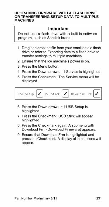
Part Number Preliminary 6/11 231
UPGRADING FIRMWARE WITH A FLASH DRIVE OR TRANSFERRING SETUP DATA TO MULTIPLE MACHINES
1. Drag and drop the file from your email onto a flash drive or refer to Exporting data to a flash drive to transfer settings to multiple machines.
2. Ensure that the ice machine’s power is on.
3. Press the Menu button.
4. Press the Down arrow until Service is highlighted.
5. Press the Checkmark. The Service menu will be displayed.
6. Press the Down arrow until USB Setup is highlighted.
7. Press the Checkmark. USB Stick will appear highlighted.
8. Press the Checkmark again. A submenu with Download Frm (Download Firmware) appears.
9. Ensure that Download Frm is highlighted and press the Checkmark. A display of instructions will appear.
ImportantDo not use a flash drive with a built-in softwareprogram, such as Sandisk brand.
USB Setup USB Stick Download Frm
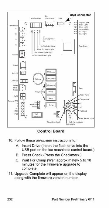
232 Part Number Preliminary 6/11
Control Board
10. Follow these on-screen instructions to:
A. Insert Drive (Insert the flash drive into the USB port on the ice machine’s control board.)
B. Press Check (Press the Checkmark.)
C. Wait For Comp (Wait approximately 5 to 10 minutes for the Firmware upgrade to complete.
11. Upgrade Complete will appear on the display, along with the firmware version number.
RT Harvest
Compressor
LT Harvest
Pump
Water
Dump
Display LightMicro LightClean LightHarvest LightSL-1 LightSL-2 Light
Fuse
Thermistors
T1
T2
T3
T4
Display
RS485
Bin LED
WaterLevelProbe
AuCS
Remote CVD
LuminIce
Transformer
Battery
Bin SwitchesBin Thermostat USB
Ice Thickness Probe Light
Water Level Probe Light
Right Bin Switch Light
Left Bin Switch Light
Dump Valve
HPC
IceThickness
Probe
Water Pump
Compressor
L1
Not Used
L2
Water Inlet Valve
Right Harvest Valve
Left Harvest ValveDump Valve
Relay Lights
VC
LPCHPC1
HPC2 CVD Contactor
USB Connector
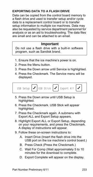
Part Number Preliminary 6/11 233
EXPORTING DATA TO A FLASH DRIVEData can be copied from the control board memory to a flash drive and used to transfer setup and/or cycle data to a replacement control board or to transfer setup information to multiple ice machines. Data may also be requested by service department personnel for analysis or as an aid to troubleshooting. The data files are small and can be attached to an email.
1. Ensure that the ice machine’s power is on.
2. Press the Menu button.
3. Press the Down arrow until Service is highlighted.
4. Press the Checkmark. The Service menu will be displayed.
5. Press the Down arrow until USB Setup is highlighted.
6. Press the Checkmark. USB Stick will appear highlighted.
7. Press the Checkmark again. A submenu with Export ALL and Export Setup appears.
8. Highlight Export ALL or Export Setup, depending on your requirements, and press the Checkmark. A display of instructions will appear.
9. Follow these on-screen instructions to:
A. Insert Drive (Insert the flash drive into the USB port on the ice machine’s control board.)
B. Press Check (Press the Checkmark.)
C. Wait For Comp (Wait approximately 5 to 10 minutes for the download to complete.
D. Export Complete will appear on the display.
ImportantDo not use a flash drive with a built-in softwareprogram, such as Sandisk brand.
USB Setup USB Stick Export All
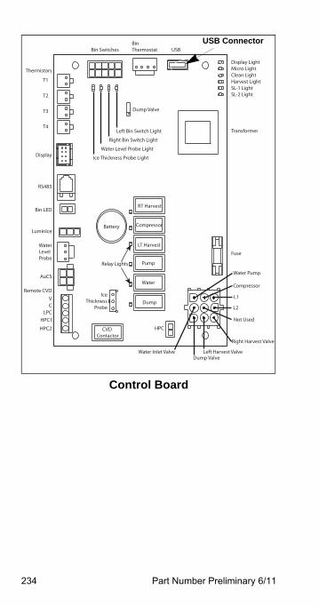
234 Part Number Preliminary 6/11
Control Board
RT Harvest
Compressor
LT Harvest
Pump
Water
Dump
Display LightMicro LightClean LightHarvest LightSL-1 LightSL-2 Light
Fuse
Thermistors
T1
T2
T3
T4
Display
RS485
Bin LED
WaterLevelProbe
AuCS
Remote CVD
LuminIce
Transformer
Battery
Bin SwitchesBin Thermostat USB
Ice Thickness Probe Light
Water Level Probe Light
Right Bin Switch Light
Left Bin Switch Light
Dump Valve
HPC
IceThickness
Probe
Water Pump
Compressor
L1
Not Used
L2
Water Inlet Valve
Right Harvest Valve
Left Harvest ValveDump Valve
Relay Lights
VC
LPCHPC1
HPC2 CVD Contactor
USB Connector
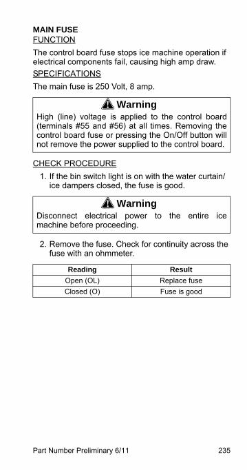
Part Number Preliminary 6/11 235
MAIN FUSEFUNCTION
The control board fuse stops ice machine operation if electrical components fail, causing high amp draw.
SPECIFICATIONS
The main fuse is 250 Volt, 8 amp.
CHECK PROCEDURE
1. If the bin switch light is on with the water curtain/ice dampers closed, the fuse is good.
2. Remove the fuse. Check for continuity across the fuse with an ohmmeter.
! WarningHigh (line) voltage is applied to the control board(terminals #55 and #56) at all times. Removing thecontrol board fuse or pressing the On/Off button willnot remove the power supplied to the control board.
! WarningDisconnect electrical power to the entire icemachine before proceeding.
Reading Result
Open (OL) Replace fuse
Closed (O) Fuse is good
236 Part Number Preliminary 6/11
BIN SWITCHFUNCTION
Movement of the water curtain/ice dampers control bin switch operation. The bin switch has two main functions:
1. Terminating the Harvest cycle and returning the ice machine to the Freeze cycle. This occurs when the bin switch is opened and closed again within 30 seconds during the Harvest cycle.
2. Automatic ice machine shut-off.If the storage bin is full at the end of a Harvest cycle, the sheet of cubes fails to clear the water curtain/ice dampers and holds it open. After the water curtain/ice dampers are held open for 30 seconds, the ice machine shuts off. The ice machine remains off until enough ice is removed from the storage bin to allow the sheet of cubes to drop clear of the water curtain/ice dampers. As the water curtain/ice dampers swing back to the operating position, the bin switch closes and the ice machine restarts, provide the 3-minute delay has expired.
SPECIFICATIONS
The bin switch is a magnetically operated reed switch. The magnet is attached to the lower right corner of the water curtain/ice dampers.
The bin switch is connected to a varying D.C. voltage circuit. (Voltage does not remain constant.)
NOTE: Because of a wide variation in D.C. voltage, it is not recommended that a voltmeter be used to check bin switch operation.
ImportantThe water curtain/ice dampers must be ON (binswitch closed) to start ice making.
Part Number Preliminary 6/11 237
DiagnosticsSYMPTOMS
Bin Switch Fails Open
• The ice machine will not start an ice making cycle and the display indicates “Curtain Open”.
• The ice machine will run in the clean cycle.
Bin Switch Fails Closed
• When running a “Long Harvest” alert is displayed and safety limit 2 indicated.
• May be off on a safety limit 2.
• The harvest cycle continues after ice opens and closes the ice damper (harvest cycle is 3.5 minutes for single evaporators and 7 minutes for multiple evaporator models).
DIAGNOSTICS
1. Verify bin switch, damper and damper magnet are in place.
• Press the Menu button.
• Scroll down to Service and press right arrow.
• Scroll down to Diagnostics and press right arrow
• Scroll down to Inputs and press right arrow to display curtain switch readings (Curt SW1, Curt SW2, etc).
2. Open and close the ice damper(s) repeatedly while observing the display and control board lights.
A. Curtain switch cycles open/closed and control board light energizes/de-energizes - Bin switch is operating normally
B. Curtain switch remains closed and control board light remains on - Replace bin switch
C. Curtain switch remains open and control board light remains off - Go to next step
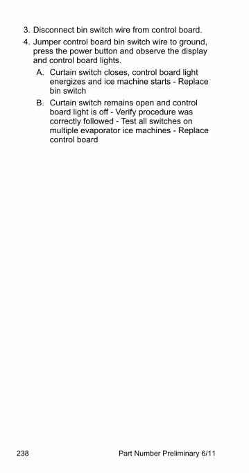
238 Part Number Preliminary 6/11
3. Disconnect bin switch wire from control board.
4. Jumper control board bin switch wire to ground, press the power button and observe the display and control board lights.
A. Curtain switch closes, control board light energizes and ice machine starts - Replace bin switch
B. Curtain switch remains open and control board light is off - Verify procedure was correctly followed - Test all switches on multiple evaporator ice machines - Replace control board
Part Number Preliminary 6/11 239
WATER LEVEL CONTROL CIRCUITRYFUNCTION
The water level probe controls the water level by sensing whether water is or is not contacting the water level probe. The water level probe has three sensing probes. Two probes are equal in length and are used to measures conductivity for diagnostics, ice clarity and water miser options. Factory default settings measure resistance from both long probes to the short probe.
SPECIFICATIONS
Freeze Cycle Water Level Setting
During the Freeze cycle, the water level probe is set to maintain the proper water level above the water pump housing. The water level is not adjustable. If the water level is incorrect, check the water level probe position. Reposition or replace the probe as necessary.
Water Inlet Valve Safety Shut-Off
In the event of a water level probe failure, this feature limits the water inlet valve to a six-minute on time. Regardless of the water level probe input, the control board automatically shuts off the water inlet valve if it remains on for 6 continuous minutes.
Freeze Cycle Operation
During the Freeze cycle, the water inlet valve energizes and de-energizes in conjunction with the water level probe located in the water trough.
During the first 45 seconds of the Freeze cycle:
• The water inlet valve is ON when there is no water in contact with the water level probes.
• The water inlet valve turns OFF after water contacts the water level probes for 3 continuous seconds.
• The water inlet valve will cycle ON and OFF as many times as needed to fill the water trough.
After 45 seconds into the Freeze cycle:The water inlet valve will cycle ON, and then OFF one more time to refill the water trough. The water inlet valve is now OFF for the duration of the freeze cycle.
240 Part Number Preliminary 6/11
DiagnosticsSYMPTOMS
• Water trough overfills
• Water trough will not fill
• Display indicates a “Long Freeze” alert and may or may not also indicate a safety limit 1
• Ice production is low
WATER TROUGH OVERFILLING DURING THE FREEZE CYCLE
Step 1 Press the power button and turn off the ice machine.Step 2 If water continues to flow with the ice machine off, disconnect power. If water continues to flow verify water pressure is below 80 psig before replacing the water inlet valve.Step 3 Check water level probe mounting and verify secure wiring connections at the probe and control board.Step 4 Scroll to Service/Diagnostics/Inputs and press down arrow until Wtr Low and Wtr High are displayed.
• No is displayed - Control board is not receiving a sensing water signal. Continue with step 5.
• Yes is displayed - Control board is receiving a sensing water signal. Clean the water level probe and test run.
Step 5 Start a new freeze cycle by pressing the power button.
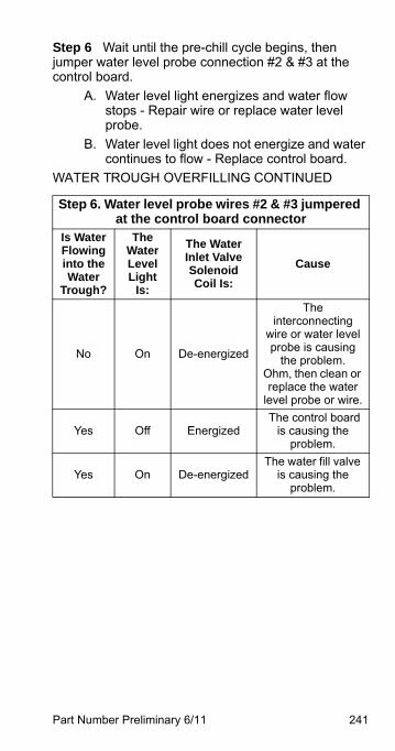
Part Number Preliminary 6/11 241
Step 6 Wait until the pre-chill cycle begins, then jumper water level probe connection #2 & #3 at the control board.
A. Water level light energizes and water flow stops - Repair wire or replace water level probe.
B. Water level light does not energize and water continues to flow - Replace control board.
WATER TROUGH OVERFILLING CONTINUED
Step 6. Water level probe wires #2 & #3 jumpered at the control board connector
Is WaterFlowinginto theWater
Trough?
TheWaterLevelLight
Is:
The WaterInlet ValveSolenoidCoil Is:
Cause
No On De-energized
The interconnecting
wire or water level probe is causing
the problem. Ohm, then clean or replace the water
level probe or wire.
Yes Off Energized The control board
is causing the problem.
Yes On De-energizedThe water fill valve
is causing the problem.
242 Part Number Preliminary 6/11
WATER WILL NOT RUN INTO THE SUMP TROUGH DURING THE FREEZE CYCLE
Step 1 Verify water is supplied to the ice machine.Step 2 Scroll to Service/Diagnostics/Inputs and press down arrow until Wtr Low and Wtr High are displayed.
A. Yes is displayed - Control board is receiving a sensing water signal. Proceed to step 3.
B. No is displayed - Control board is not receiving a sensing water signal. Proceed to Control Board Diagnostics page 228.
Step 3 Disconnect water level probe, observe LCD display text.
A. No is displayed - Clean the water level probe and test interconnecting wiring.
B. Yes is displayed - Refer to Control Board Diagnostics page 228
Part Number Preliminary 6/11 243
ICE THICKNESS PROBE (HARVEST INITIATION)FUNCTION
The ice thickness probe senses ice on the evaporator and signals the control board to start a harvest cycle. After ice forms on the evaporator, the ice will contact the ice thickness probe. After 6 - 10 seconds of continuous contact, a harvest cycle is initiated.
SPECIFICATIONS
Freeze Time Lock-In Feature
The ice machine control system incorporates a freeze time lock-in feature. This prevents the ice machine from short cycling in and out of harvest.
The control board locks the ice machine in the freeze cycle and a harvest cycle can not start for six minutes.
Maximum Freeze Time
The control system includes a built-in safety which will automatically cycle the ice machine into harvest after 60 minutes in the freeze cycle.
Maximum Temperature
Maximum temperature for the ice thickness probe is 120 degrees F (49 degree’s C). Do not clean probe in a dishwasher or expose to temperatures above the maximum.
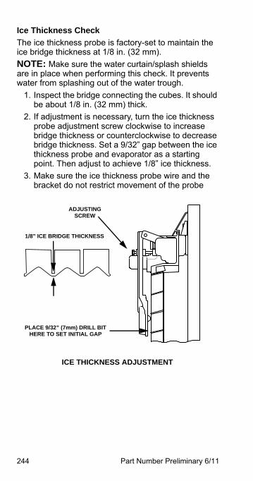
244 Part Number Preliminary 6/11
Ice Thickness Check
The ice thickness probe is factory-set to maintain the ice bridge thickness at 1/8 in. (32 mm).
NOTE: Make sure the water curtain/splash shields are in place when performing this check. It prevents water from splashing out of the water trough.
1. Inspect the bridge connecting the cubes. It should be about 1/8 in. (32 mm) thick.
2. If adjustment is necessary, turn the ice thickness probe adjustment screw clockwise to increase bridge thickness or counterclockwise to decrease bridge thickness. Set a 9/32” gap between the ice thickness probe and evaporator as a starting point. Then adjust to achieve 1/8” ice thickness.
3. Make sure the ice thickness probe wire and the bracket do not restrict movement of the probe
ADJUSTINGSCREW
ICE THICKNESS ADJUSTMENT
1/8” ICE BRIDGE THICKNESS
PLACE 9/32” (7mm) DRILL BIT HERE TO SET INITIAL GAP
Part Number Preliminary 6/11 245
DiagnosticsSYMPTOMS
Premature harvest
• Display indicates ITP Failure
• Low ice production
• Thin ice in bin
• Freeze cycles are faster than published cycle times
Will not harvest
• Display indicates ITP Failure
• Low ice production
• Thick ice in bin
• Large sheet of ice on evaporator
• Harvest cycle doesn’t start
• Freeze cycles are slower than published cycle times
ICE MACHINE CYCLES INTO HARVEST BEFORE ICE CONTACTS THE ICE THICKNESS PROBE
1. Reboot the control board by disconnecting and reconnecting line voltage to the ice machine.
2. Verify ice thickness probe gap is approximately9/32” (7 mm).
3. Wait six minutes:
• Ice Machine remains in freeze cycle - Allow ice machine to run.
• Ice machine cycles into harvest - Replace ice thickness probe to determine if problem is resolved. If problem persists replace the control board.
246 Part Number Preliminary 6/11
ICE MACHINE DOES NOT CYCLE INTO HARVEST
If ice is on the evaporator initiate a manual harvest cycle by performing the following keystrokes.
• Press Menu
• Scroll down to Service and press right arrow
• Scroll down to Manual Harvest and press right arrow - A new freeze cycle will start after the manual harvest cycle is complete.
1. Reboot the control board by disconnecting and reconnecting line voltage to the ice machine.
2. Verify ice thickness probe gap is approximately9/32” (7 mm).
3. Wait for ice to contact the ice thickness probe.
• Ice Machine cycles into harvest normally - Allow ice machine to run.
• Ice machine will not cycle into harvest - Replace ice thickness probe to determine if problem is resolved. If problem persists replace the control board.
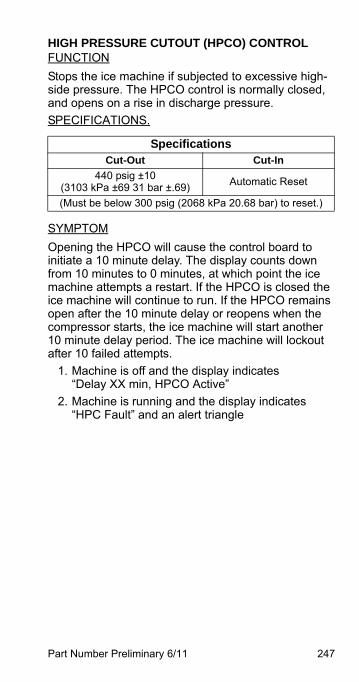
Part Number Preliminary 6/11 247
HIGH PRESSURE CUTOUT (HPCO) CONTROLFUNCTION
Stops the ice machine if subjected to excessive high-side pressure. The HPCO control is normally closed, and opens on a rise in discharge pressure.
SPECIFICATIONS.
SYMPTOM
Opening the HPCO will cause the control board to initiate a 10 minute delay. The display counts down from 10 minutes to 0 minutes, at which point the ice machine attempts a restart. If the HPCO is closed the ice machine will continue to run. If the HPCO remains open after the 10 minute delay or reopens when the compressor starts, the ice machine will start another 10 minute delay period. The ice machine will lockout after 10 failed attempts.
1. Machine is off and the display indicates“Delay XX min, HPCO Active”
2. Machine is running and the display indicates “HPC Fault” and an alert triangle
SpecificationsCut-Out Cut-In
440 psig ±10(3103 kPa ±69 31 bar ±.69)
Automatic Reset
(Must be below 300 psig (2068 kPa 20.68 bar) to reset.)
248 Part Number Preliminary 6/11
CHECK PROCEDURE
Symptom #1 Machine is off and the display indicates “Delay xx min, HPCO Active”.
1. Leave all wiring connectors attached and perform testing within the 10 minute time delay period
2. Check for line voltage at P9 connector on control board (Two wire connector adjacent to 9 pin connector).
A. Line voltage present - HPCO switch has reset and closed.
B. No line voltage present - HPCO switch is open. Verify pressure - Below cut-in replace HPCO - Above cut-in find root cause problem.
3. Wait for the 10 minute delay to end. The ice machine will go to an initial start sequence. When the compressor relay closes the control board checks the HPCO
A. HPCO is open - Another 10 minute delay period starts.
B. HPCO closed - A 3.5 minute harvest cycle starts followed by an ice making cycle.
4. Run the system to see if the control trips at the rated pressure. If HPCO opens at a pressure significantly lower or higher than the control setting of 440 psig replace the HPCO.
5. If the control opens at the correct pressure find the root cause - Fan motor, dirty condenser, refrigeration system issue, etc.
Part Number Preliminary 6/11 249
Symptom #2 Machine is running and the display indicates “HPC Fault” and an alert triangle
1. Navigate to the event log on the Service menu. Scroll down to HPC Fault #5. Open the event and view when and how often HPCO Fault has occurred.
2. If this is a one time event it may be intermittent and caused by conditions around the unit changing. For example: High ambient temperature, water turned off to condenser (water cooled unit) etc.
3. Run the system to see if the control trips at the rated pressure. If HPCO opens at a pressure significantly lower than the control setting of 440 psig replace the HPCO.
4. If the control opens at the correct pressure (+-10 lbs) find the root cause - Fan motor, dirty condenser, refrigeration system issue, etc.
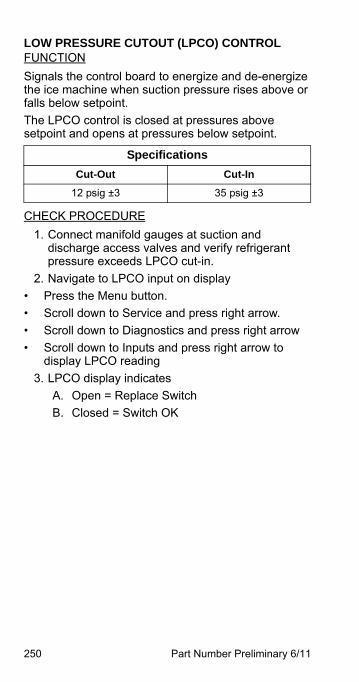
250 Part Number Preliminary 6/11
LOW PRESSURE CUTOUT (LPCO) CONTROLFUNCTION
Signals the control board to energize and de-energize the ice machine when suction pressure rises above or falls below setpoint.
The LPCO control is closed at pressures above setpoint and opens at pressures below setpoint.
CHECK PROCEDURE
1. Connect manifold gauges at suction and discharge access valves and verify refrigerant pressure exceeds LPCO cut-in.
2. Navigate to LPCO input on display
• Press the Menu button.
• Scroll down to Service and press right arrow.
• Scroll down to Diagnostics and press right arrow
• Scroll down to Inputs and press right arrow to display LPCO reading
3. LPCO display indicates
A. Open = Replace Switch
B. Closed = Switch OK
Specifications
Cut-Out Cut-In
12 psig ±3 35 psig ±3
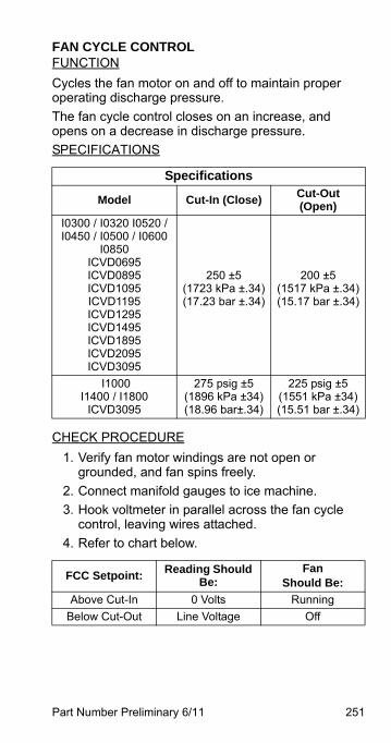
Part Number Preliminary 6/11 251
FAN CYCLE CONTROLFUNCTION
Cycles the fan motor on and off to maintain proper operating discharge pressure.
The fan cycle control closes on an increase, and opens on a decrease in discharge pressure.
SPECIFICATIONS
CHECK PROCEDURE
1. Verify fan motor windings are not open or grounded, and fan spins freely.
2. Connect manifold gauges to ice machine.
3. Hook voltmeter in parallel across the fan cycle control, leaving wires attached.
4. Refer to chart below.
Specifications
Model Cut-In (Close)Cut-Out (Open)
I0300 / I0320 I0520 / I0450 / I0500 / I0600
I0850ICVD0695ICVD0895ICVD1095ICVD1195ICVD1295ICVD1495ICVD1895ICVD2095ICVD3095
250 ±5(1723 kPa ±.34)(17.23 bar ±.34)
200 ±5(1517 kPa ±.34)(15.17 bar ±.34)
I1000I1400 / I1800
ICVD3095
275 psig ±5(1896 kPa ±34)(18.96 bar±.34)
225 psig ±5(1551 kPa ±34)(15.51 bar ±.34)
FCC Setpoint:Reading Should
Be:Fan
Should Be:
Above Cut-In 0 Volts Running
Below Cut-Out Line Voltage Off
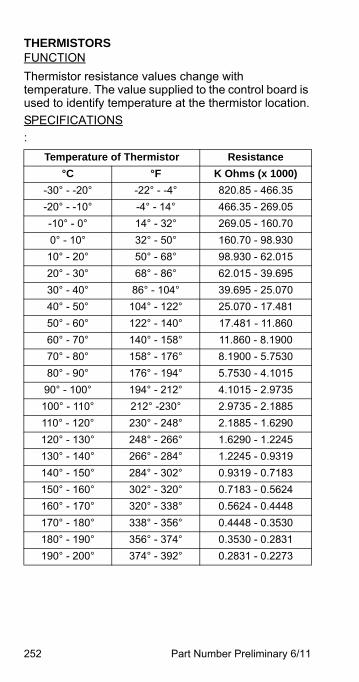
252 Part Number Preliminary 6/11
THERMISTORSFUNCTION
Thermistor resistance values change with temperature. The value supplied to the control board is used to identify temperature at the thermistor location.
SPECIFICATIONS
:
Temperature of Thermistor Resistance
°C °F K Ohms (x 1000)
-30° - -20° -22° - -4° 820.85 - 466.35
-20° - -10° -4° - 14° 466.35 - 269.05
-10° - 0° 14° - 32° 269.05 - 160.70
0° - 10° 32° - 50° 160.70 - 98.930
10° - 20° 50° - 68° 98.930 - 62.015
20° - 30° 68° - 86° 62.015 - 39.695
30° - 40° 86° - 104° 39.695 - 25.070
40° - 50° 104° - 122° 25.070 - 17.481
50° - 60° 122° - 140° 17.481 - 11.860
60° - 70° 140° - 158° 11.860 - 8.1900
70° - 80° 158° - 176° 8.1900 - 5.7530
80° - 90° 176° - 194° 5.7530 - 4.1015
90° - 100° 194° - 212° 4.1015 - 2.9735
100° - 110° 212° -230° 2.9735 - 2.1885
110° - 120° 230° - 248° 2.1885 - 1.6290
120° - 130° 248° - 266° 1.6290 - 1.2245
130° - 140° 266° - 284° 1.2245 - 0.9319
140° - 150° 284° - 302° 0.9319 - 0.7183
150° - 160° 302° - 320° 0.7183 - 0.5624
160° - 170° 320° - 338° 0.5624 - 0.4448
170° - 180° 338° - 356° 0.4448 - 0.3530
180° - 190° 356° - 374° 0.3530 - 0.2831
190° - 200° 374° - 392° 0.2831 - 0.2273

Part Number Preliminary 6/11 253
Four thermistors are located on the ice machine. They are labeled T1, T2, T3, T4
T1 - Air or Water cooled Models
• Liquid line temperature sensor located at the outlet of the condenser.
T1 - Remote Condenser or Remote Condensing Unit Models
• Liquid line temperature sensor located at the inlet of the receiver.
T2 - Air or Water cooled Models
• Discharge line temperature sensor located near the compressor.
T2 - Remote Condenser or Remote Condensing Unit Models
• Liquid line temperature sensor located at the outlet of the receiver.
T3 -Single Expansion Valve Models
• Suction line temperature sensor located at the inlet of the evaporator.
T3 - Multiple Evaporator Models
• Suction line temperature sensor located at the outlet of evaporator #1.
T4 -Single Expansion Valve Models
• Suction line temperature sensor located at the outlet of the evaporator.
T4 - Multiple Evaporator Models
• Suction line temperature sensor located at the outlet of evaporator #2.
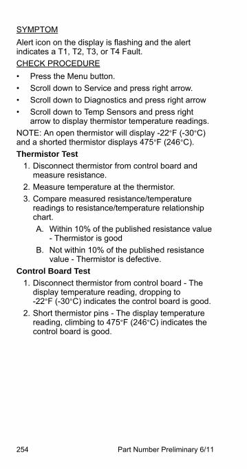
254 Part Number Preliminary 6/11
SYMPTOM
Alert icon on the display is flashing and the alert indicates a T1, T2, T3, or T4 Fault.
CHECK PROCEDURE
• Press the Menu button.
• Scroll down to Service and press right arrow.
• Scroll down to Diagnostics and press right arrow
• Scroll down to Temp Sensors and press right arrow to display thermistor temperature readings.
NOTE: An open thermistor will display -22°F (-30°C) and a shorted thermistor displays 475°F (246°C).
Thermistor Test
1. Disconnect thermistor from control board and measure resistance.
2. Measure temperature at the thermistor.
3. Compare measured resistance/temperature readings to resistance/temperature relationship chart.
A. Within 10% of the published resistance value - Thermistor is good
B. Not within 10% of the published resistance value - Thermistor is defective.
Control Board Test
1. Disconnect thermistor from control board - The display temperature reading, dropping to -22°F (-30°C) indicates the control board is good.
2. Short thermistor pins - The display temperature reading, climbing to 475°F (246°C) indicates the control board is good.
Part Number Preliminary 6/11 255
HARVEST ASSIST AIR PUMPFUNCTION
The air pump breaks the vacuum between the sheet of ice and the evaporator which results in shorter harvest cycles.
SPECIFICATIONS
115 Volt or 230 Volt - matches the ice machine voltage.
CHECK PROCEDURE
1. The air pump is wired in parallel with the harvest valve - Verify the ice machine is in the harvest cycle and the harvest valve is energized.
2. If there is voltage at the air pump connector, use a volt ohm meter to verify there is no continuity through the motor windings then replace motor.

256 Part Number Preliminary 6/11
COMPRESSOR ELECTRICAL DIAGNOSTICSThe compressor does not start or will trip repeatedly on overload.
Check Resistance (Ohm) Values
NOTE: Compressor windings can have very low ohm values. Use a properly calibrated meter.
Perform the resistance test after the compressor cools. The compressor dome should be cool enough to touch (below 120°F/49°C) to assure that the overload is closed and the resistance readings will be accurate.
SINGLE PHASE COMPRESSORS
1. Disconnect power then remove the wires from the compressor terminals.
2. The resistance values between C and S and between C and R, when added together, should equal the resistance value between S and R.
3. If the overload is open, there will be a resistance reading between S and R, and open readings between C and S and between C and R. Allow the compressor to cool, then check the readings again.
THREE PHASE COMPRESSORS
1. Disconnect power and remove the wires from the compressor terminals.
2. The resistance values between L1 and L2, between L2 and L3, and between L3 and L1 should all be equal.
3. If the overload is open, there will be open readings between L1 and L2, between L2 and L3, and between L3 and L1. Allow the compressor to cool, then check the readings again.

Part Number Preliminary 6/11 257
CHECK MOTOR WINDINGS TO GROUND
Check continuity between all three terminals and the compressor shell or copper refrigeration line. Scrape metal surface to get good contact. If continuity is present, the compressor windings are grounded and the compressor should be replaced.
COMPRESSOR DRAWING LOCKED ROTOR
To determine if the compressor is seized, check the amp draw while the compressor is trying to start.
The two likely causes of this are a defective starting component and a mechanically seized compressor.
To determine which you have:
1. Install high and low side gauges.
2. Try to start the compressor.
3. Watch the pressures closely.
A. If the pressures do not move, the compressor is seized. Replace the compressor.
B. If the pressures move, the compressor is turning slowly and is not seized. Check the capacitors and relay.
COMPRESSOR DRAWING HIGH AMPS
The continuous amperage draw on start-up should not be near the maximum fuse size indicated on the serial tag.
258 Part Number Preliminary 6/11
DIAGNOSING START COMPONENTSIf the compressor attempts to start, or hums and trips the overload protector, check the start components before replacing the compressor.
Capacitor
Visual evidence of capacitor failure can include a bulged terminal end or a ruptured membrane. Do not assume a capacitor is good if no visual evidence is present. A good test is to install a known good substitute capacitor. Use a capacitor tester when checking a suspect capacitor. Clip the bleed resistor off the capacitor terminals before testing.
• If the compressor attempts to start, or hums and trips the overload protector, check the starting components before replacing the compressor.
• Visual evidence of capacitor failure can include a bulged terminal end or a ruptured membrane. Do not assume a capacitor is good if no visual evidence is present.
• A good test is to install a known good substitute capacitor.
• Use a capacitor tester when checking a suspect capacitor. Clip the bleed resistor off the capacitor terminals before testing.
Part Number Preliminary 6/11 259
Relay
The relay has a set of contacts that connect and disconnect the start capacitor from the compressor start winding. The contacts on the relay are normally closed (start capacitor in series with the start winding). The relay senses the voltage generated by the start winding and opens the contacts as the compressor motor starts. The contacts remain open until the compressor is de-energized.
RELAY OPERATION CHECK
1. Disconnect wires from relay terminals.
2. Verify the contacts are closed.Measure the resistance between terminals 1 and 2. No continuity indicates open contacts. Replace the relay.
3. Check the relay coil.Measure the resistance between terminals 2 and 5. No resistance indicates an open coil. Replace the relay.
260 Part Number Preliminary 6/11
PTCR
The PTCR allows current to flow through the start winding at compressor startup. Current flow heats the ceramic discs in the PTCR. The electrical resistance increases with temperature and stops all except a trickle of current flow through the start winding. The small flow of current keeps the PTCR hot (260°F/127°C) and the start winding out of the circuit.
The PTCR must be cooled before attempting to start the compressor, otherwise the PTCR will heat up too quickly and stop current flow through the start winding before the compressor motor reaches full speed.
NOTE: If a PTCR is dropped internal damage can occur to the ceramic PTCR discs. The ceramic disc can chip and cause arcing which leads to PTCR failure. Since there is no way to open the PTCR in order to determine if the ceramic disc is chipped or not, it must be discarded when dropped.
! WarningDisconnect electrical power to the entire icemachine at the building electrical disconnect boxbefore proceeding.
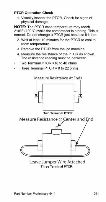
Part Number Preliminary 6/11 261
PTCR Operation Check
1. Visually inspect the PTCR. Check for signs of physical damage.
NOTE: The PTCR case temperature may reach 210°F (100°C) while the compressor is running. This is normal. Do not change a PTCR just because it is hot.
2. Wait at least 10 minutes for the PTCR to cool to room temperature.
3. Remove the PTCR from the ice machine.
4. Measure the resistance of the PTCR as shown. The resistance reading must be between:
• Two Terminal PTCR =18 to 40 ohms
• Three Terminal PTCR = 8 to 22 ohms.
Three Terminal PTCR
Measure Resistance At Ends
Two Terminal PTCR
Leave Jumper Wire Attached
Measure Resistance @ Center and End

262 Part Number Preliminary 6/11
This Page Intentionally Left Blank
Part Number Preliminary 6/11 263
Refrigeration Components
HEAD PRESSURE CONTROL VALVEManitowoc remote systems require head pressure control valves with special settings. Replace defective head pressure control valves only with “original” Manitowoc replacement parts.
Refrigerant Charge Verification
The correct amount of refrigerant (name plate charge) is required to operate correctly at all ambient conditions.
An ice machine with an overcharge or undercharge of refrigerant may function properly at higher ambient temperatures and fails at lower ambient temperatures. Symptoms of incorrect refrigerant amount are:
• Works during the day and malfunctions at night, and/or fails whenever the outdoor temperature drops.
• A Safety limit is stored in control board memory.
Refrigerant loss and ambient temperature are directly related to each other. As the ambient temperature drops, more refrigerant is stored in the condenser.
When the refrigerant charge and ambient temperature create an undercharge of refrigerant in the freeze cycle, the receiver dip tube will lose it’s liquid seal. Without liquid refrigerant to the TXV, the ice machine fails to make a full sheet of ice in 60 minutes and a safety limit #1 results.
NOTE: When a head pressure control valve is being replaced or refrigerant charge is suspected, verify the refrigerant charge is correct by recovering the refrigerant, weighing and comparing to the nameplate amount. Refer to Refrigerant Recovery/Evacuation” page 280 for recovery procedures.
264 Part Number Preliminary 6/11
Freeze Cycle Operation All Models
The R404A head pressure control valve is non adjustable.
At ambient temperatures of approximately 70°F (21°C) or above, refrigerant flows through the valve from the condenser to the receiver inlet. At temperatures below this (or at higher temperatures if it is raining), the head pressure control dome’s nitrogen charge closes the condenser port and opens the bypass port from the compressor discharge line.
In this modulating mode, the valve maintains minimum head pressure by building up liquid in the condenser and bypassing discharge gas directly to the receiver.
Harvest Cycle OperationRemote Condenser Models
The head pressure control cycles into full bypass due to the pressure drop when the harvest valve opens. Refrigerant flows from the compressor to the evaporator through the harvest valve and the head pressure valve is out of the circuit.
Part Number Preliminary 6/11 265
Harvest Cycle OperationQuietQube® Models
During the Harvest cycle, the harvest valve opens and allows refrigerant from the top of the receiver tank to enter the evaporator. The refrigerants change of state (from vapor to liquid) releases the heat necessary for the Harvest cycle.
Opening the harvest valve causes a drop in discharge pressure.
The discharge pressure will drop below the condenser fan cycling control setpoint and the condenser fan motor cycles off (at ambient temperatures above 110°F (43°C) the condenser fan motor remains energized).
The warm discharge gas adds heat to the receiver in the harvest cycle. Without this additional heat the head pressure would continue to drop as liquid refrigerant boils off in the receiver.
Example: A service technician removes refrigerant vapor from a cylinder by boiling off the liquid refrigerant. A refrigeration effect is created as the refrigerant changes state from a liquid to a vapor. The cylinder cools and the refrigerant pressure drops. To maximize flow and maintain pressure the technician places the cylinder in warm water.
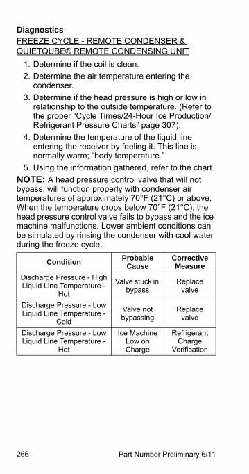
266 Part Number Preliminary 6/11
DiagnosticsFREEZE CYCLE - REMOTE CONDENSER & QUIETQUBE® REMOTE CONDENSING UNIT
1. Determine if the coil is clean.
2. Determine the air temperature entering the condenser.
3. Determine if the head pressure is high or low in relationship to the outside temperature. (Refer to the proper “Cycle Times/24-Hour Ice Production/Refrigerant Pressure Charts” page 307).
4. Determine the temperature of the liquid line entering the receiver by feeling it. This line is normally warm; “body temperature.”
5. Using the information gathered, refer to the chart.
NOTE: A head pressure control valve that will not bypass, will function properly with condenser air temperatures of approximately 70°F (21°C) or above. When the temperature drops below 70°F (21°C), the head pressure control valve fails to bypass and the ice machine malfunctions. Lower ambient conditions can be simulated by rinsing the condenser with cool water during the freeze cycle.
ConditionProbable
CauseCorrective Measure
Discharge Pressure - HighLiquid Line Temperature -
Hot
Valve stuck in bypass
Replace valve
Discharge Pressure - LowLiquid Line Temperature -
Cold
Valve not bypassing
Replace valve
Discharge Pressure - LowLiquid Line Temperature -
Hot
Ice Machine Low on Charge
Refrigerant Charge
Verification
Part Number Preliminary 6/11 267
Harvest CycleREMOTE CONDENSER
The head pressure control cycles into full bypass due to the pressure drop when the harvest valve opens. Refrigerant flows from the compressor to the evaporator through the harvest valve and the head pressure valve is out of the circuit.
QUIETQUBE ® REMOTE CONDENSING UNIT
QuietQube® ice machines may fail in the harvest cycle when the refrigerant charge and ambient temperature create a marginal undercharge of refrigerant. The ice machine may be able to make a full sheet of ice, but fails in the harvest cycle when the receiver runs out of liquid refrigerant. A safety limit #2 will result when the ice machine is unable to harvest.
Undercharge Symptoms
• Safety limit #1 or Safety limit #2 in control board memory.
• Harvest cycle suction pressure is low.
• Harvest cycle discharge pressure is low.
• Liquid line entering receiver feels warm to hot in the freeze cycle.
Overcharge Symptoms
• Safety limit #2 in control board memory.
• Harvest cycle suction pressure is low.
• Harvest cycle discharge pressure is normal.
• Freeze cycle time, suction and discharge pressure are normal and the ice machine will not harvest. The sheet of ice cubes show little or no sign of melting when removed from the evaporator after the harvest cycle has been completed. (If the cubes are melted you have a release problem, clean the ice machine).
268 Part Number Preliminary 6/11
HARVEST CYCLE DIAGNOSTICS QUIETQUBE ® REMOTE CONDENSING UNIT
The headmaster control valve diverts the compressor discharge gas to the ice machine receiver in the harvest cycle. All refrigerant flow through the condenser in the harvest cycle stops. Symptoms of a headmaster valve that will not seat 100% closed (completely bypass the condenser) in the harvest cycle are:
• Freeze cycle suction and discharge pressure are normal.
• The control board indicates safety limit #2. The failure seems to be temperature related. Example: The ice machine may function correctly at temperatures above 32°F but fails at temperatures below 32°F.
• Harvest cycle suction pressure is low.
• Harvest cycle discharge pressure is normal or slightly low.
Procedure
1. Freeze cycle operation must be normal before diagnosing the headmaster in the harvest cycle. (Refer to Cycle Times/24 hr Ice Production/Refrigerant Pressure Chart)
2. Allow the ice machine to run a normal freeze cycle (do not initiate an early harvest cycle).
3. At the start of the harvest cycle feel the compressor discharge line and the liquid line to the ice machine receiver at the headmaster valve. The temperature of both lines will be highest at the beginning of the harvest cycle and then decrease. Compare the lines 30 seconds into the harvest cycle and then refer to Harvest Cycle Headmaster Control Valve Failure List page 273.
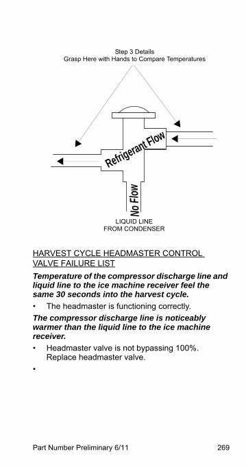
Part Number Preliminary 6/11 269
HARVEST CYCLE HEADMASTER CONTROL VALVE FAILURE LIST
Temperature of the compressor discharge line and liquid line to the ice machine receiver feel the same 30 seconds into the harvest cycle.
• The headmaster is functioning correctly.
The compressor discharge line is noticeably warmer than the liquid line to the ice machine receiver.
• Headmaster valve is not bypassing 100%. Replace headmaster valve.
•
Refrigerant FlowNo
Flow
Step 3 DetailsGrasp Here with Hands to Compare Temperatures
LIQUID LINE FROM CONDENSER
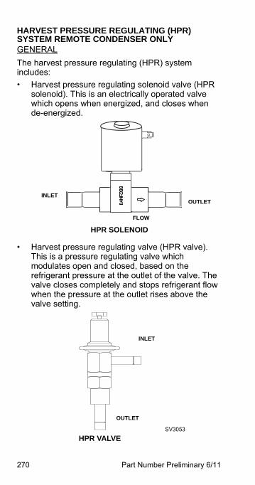
270 Part Number Preliminary 6/11
HARVEST PRESSURE REGULATING (HPR) SYSTEM REMOTE CONDENSER ONLYGENERAL
The harvest pressure regulating (HPR) system includes:
• Harvest pressure regulating solenoid valve (HPR solenoid). This is an electrically operated valve which opens when energized, and closes when de-energized.
• Harvest pressure regulating valve (HPR valve). This is a pressure regulating valve which modulates open and closed, based on the refrigerant pressure at the outlet of the valve. The valve closes completely and stops refrigerant flow when the pressure at the outlet rises above the valve setting.
INLETOUTLET
FLOW
HPR SOLENOID
SV3053
OUTLET
INLET
HPR VALVE
Part Number Preliminary 6/11 271
FREEZE CYCLE
The HPR system is not used during the freeze cycle. The HPR solenoid is closed (de-energized), preventing refrigerant flow into the HPR valve.
HARVEST CYCLE
During the harvest cycle, the check valve in the discharge line prevents refrigerant in the remote condenser and receiver from back feeding into the evaporator and condensing to liquid.
The HPR solenoid is opened (energized) during the harvest cycle, allowing refrigerant gas from the top of the receiver to flow into the HPR valve. The HPR valve modulates open and closed, raising the suction pressure high enough to sustain heat for the harvest cycle, without allowing refrigerant to condense to liquid in the evaporator.
In general, harvest cycle suction pressure rises, then stabilizes in the range of 70-100 psig (517-758 kPa). Exact pressures vary from model to model. Refer to cycle time/24 hour ice production and operational pressure charts.
HPR DIAGNOSTICS
Steps 1 through 4 can be quickly verified without attaching a manifold gauge set or thermometer.
All questions must have a yes answer to continue the diagnostic procedure.
1. Liquid line warm?(Body temperature is normal) If liquid line is cooler than body temperature, refer to head pressure control valve diagnostics page 273.
2. Ice fill pattern normal? Refer to “Ice Formation Pattern” if ice fill is not normal page 164.
272 Part Number Preliminary 6/11
3. Freeze time normal? (Refer to Cycle Times/Refrigerant Pressures/24 Hour Ice Production Charts page 307)Shorter freeze cycles - Refer to head pressure control valve diagnostics page 273.Longer freeze cycles - Refer to water system checklist page 163, then refer to Refrigeration Diagnostic Procedures.
4. Harvest time is longer than normal and control board indicates safety limit #2?(Refer to Cycle Times/Refrigerant Pressures/24 Hour Ice Production Charts page 307)Connect refrigeration manifold gauge set to the access valves on the front of the ice machine.Establish baseline by recording suction and discharge pressure and freeze & harvest cycle times. (Refer to “Freeze Cycle Refrigeration System Operational Analysis Tables” for data collection detail page 144).
5. Discharge line temperature is greater than 150°F (66°C) [I0850/I1000 Air/Water Only - 140°F (60°C)] at the end of the freeze cycle? (See Discharge Line Temperature Analysis on page 176)
6. Freeze cycle Head Pressure is in the range indicated in the cycle time/24 hour ice production and operational pressure chart?If the head pressure is low refer to head pressure control valve diagnostics page 273.
7. Freeze cycle Suction Pressure normal? Refer to analyzing suction pressure if suction pressure is high or low page 169.
8. Harvest cycle suction and discharge pressures are lower than indicated in the cycle times/refrigerant pressures/24 hour ice production chart? Replace Harvest Pressure Regulating solenoid.
Part Number Preliminary 6/11 273
WATER REGULATING VALVEWater-Cooled Models Only
FUNCTION
The water regulating valve maintains the freeze cycle discharge pressure.
CHECK PROCEDURE
1. Determine if the head pressure is high or low (refer to cycle time/24 hour ice production and operational pressure chart for the model you are servicing).
2. Verify the condenser water meets specifications.
3. Adjust valve to increase or decrease discharge pressure.
4. Determine the temperature of the liquid line entering the receiver by feeling it. This line is normally warm; body temperature.
5. Using the information gathered, refer to the list for diagnosis.
Problem (Freeze Cycle)
Valve not maintaining discharge pressure.
• Valve incorrectly set, dirty or defective. Adjust, clean or replace valve.
Discharge pressure extremely high; Liquid line entering receiver feels hot.
• Water regulating valve incorrectly set or not opening.
Discharge pressure low, Liquid line entering receiver feels warm to hot.
• Ice machine low on charge. Verify Total System Refrigerant Charge page 301.
274 Part Number Preliminary 6/11
HARVEST PRESSURE SOLENOID VALVE
(I3300W Only)FUNCTION
Transfers refrigerant from the high side to the low side during the harvest cycle.
CHECK PROCEDURE
1. Reset the ice machine with the power button to over ride the 6 minute freeze lock.
2. Initiate a manual harvest cycle.
3. Verify the coil has line voltage supplied in the harvest cycle and magnetism is present
4. If voltage and magnetism are present refer to Quad evaporator operational analysis chart page 153.
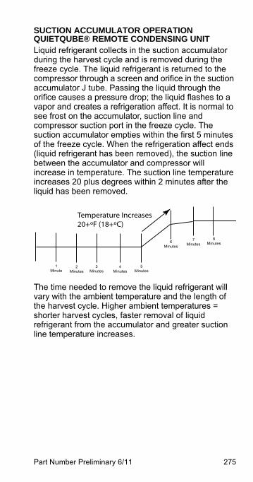
Part Number Preliminary 6/11 275
SUCTION ACCUMULATOR OPERATION QUIETQUBE® REMOTE CONDENSING UNIT Liquid refrigerant collects in the suction accumulator during the harvest cycle and is removed during the freeze cycle. The liquid refrigerant is returned to the compressor through a screen and orifice in the suction accumulator J tube. Passing the liquid through the orifice causes a pressure drop; the liquid flashes to a vapor and creates a refrigeration affect. It is normal to see frost on the accumulator, suction line and compressor suction port in the freeze cycle. The suction accumulator empties within the first 5 minutes of the freeze cycle. When the refrigeration affect ends (liquid refrigerant has been removed), the suction line between the accumulator and compressor will increase in temperature. The suction line temperature increases 20 plus degrees within 2 minutes after the liquid has been removed.
The time needed to remove the liquid refrigerant will vary with the ambient temperature and the length of the harvest cycle. Higher ambient temperatures = shorter harvest cycles, faster removal of liquid refrigerant from the accumulator and greater suction line temperature increases.
1Minute
2Minutes
3Minutes
4Minutes
5Minutes
6Minutes
7Minutes
8Minutes
Temperature Increases20+ºF (18+ºC)
276 Part Number Preliminary 6/11
Refrigerant Recovery/Evacuation
SELF-CONTAINED MODEL PROCEDUREDo not purge refrigerant to the atmosphere. Capture refrigerant using recovery equipment. Follow the manufacturer’s recommendations.
Connections
Manifold gauge sets must utilize low loss fittings to comply with U.S. Government rules and regulations.
Make these connections:
• Suction side of the compressor through the suction service valve.
• Discharge side of the compressor through the discharge service valve.
ImportantManitowoc assumes no responsibility for the use ofcontaminated refrigerant. Damage resulting from theuse of contaminated refrigerant is the soleresponsibility of the servicing company.
ImportantReplace the liquid line drier after recovering therefrigerant and before evacuating and recharging.Use only a Manitowoc (OEM) liquid line filter-drier toprevent voiding the warranty.
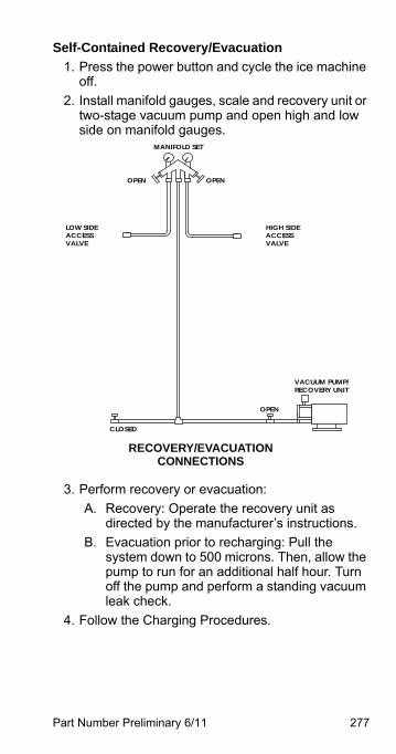
Part Number Preliminary 6/11 277
Self-Contained Recovery/Evacuation
1. Press the power button and cycle the ice machine off.
2. Install manifold gauges, scale and recovery unit or two-stage vacuum pump and open high and low side on manifold gauges.
3. Perform recovery or evacuation:
A. Recovery: Operate the recovery unit as directed by the manufacturer’s instructions.
B. Evacuation prior to recharging: Pull the system down to 500 microns. Then, allow the pump to run for an additional half hour. Turn off the pump and perform a standing vacuum leak check.
4. Follow the Charging Procedures.
MANIFOLD SET
OPEN
VACUUM PUMP/RECOVERY UNIT
CLOSED
OPEN
LOW SIDEACCESSVALVE
HIGH SIDEACCESSVALVE
OPEN
RECOVERY/EVACUATIONCONNECTIONS
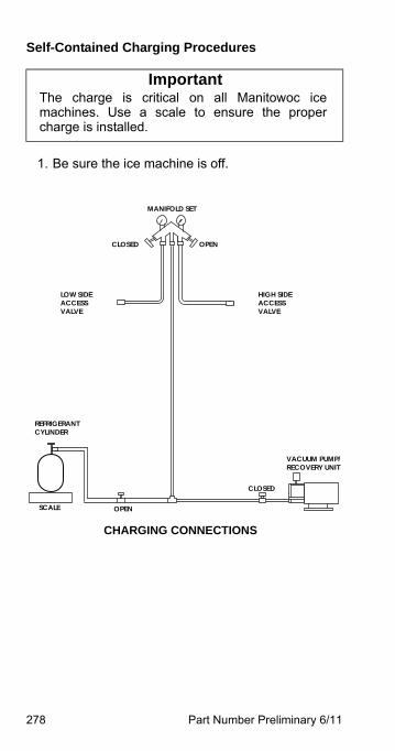
278 Part Number Preliminary 6/11
Self-Contained Charging Procedures
1. Be sure the ice machine is off.
ImportantThe charge is critical on all Manitowoc icemachines. Use a scale to ensure the propercharge is installed.
MANIFOLD SET
CLOSED
SCALE
VACUUM PUMP/RECOVERY UNIT
OPEN
CLOSED
LOW SIDEACCESSVALVE
HIGH SIDEACCESSVALVE
OPEN
REFRIGERANTCYLINDER
CHARGING CONNECTIONS
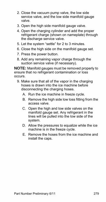
Part Number Preliminary 6/11 279
2. Close the vacuum pump valve, the low side service valve, and the low side manifold gauge valve.
3. Open the high side manifold gauge valve.
4. Open the charging cylinder and add the proper refrigerant charge (shown on nameplate) through the discharge service valve.
5. Let the system “settle” for 2 to 3 minutes.
6. Close the high side on the manifold gauge set.
7. Press the power button.
8. Add any remaining vapor charge through the suction service valve (if necessary).
NOTE: Manifold gauges must be removed properly to ensure that no refrigerant contamination or loss occurs.
9. Make sure that all of the vapor in the charging hoses is drawn into the ice machine before disconnecting the charging hoses.
A. Run the ice machine in freeze cycle.
B. Remove the high side low loss fitting from the access valve.
C. Open the high and low side valves on the manifold gauge set. Any refrigerant in the lines will be pulled into the low side of the system.
D. Allow the pressures to equalize while the ice machine is in the freeze cycle.
E. Remove the hoses from the ice machine and install the caps.
280 Part Number Preliminary 6/11
REMOTE CONDENSER MODEL PROCEDURE
Refrigerant Recovery/Evacuation
Do not purge refrigerant to the atmosphere. Capture refrigerant using recovery equipment. Follow the manufacturer’s recommendations.
ImportantManitowoc Ice assumes no responsibility for theuse of contaminated refrigerant. Damageresulting from the use of contaminated refrigerantis the sole responsibility of the servicingcompany.
ImportantReplace the liquid line drier after recovering therefrigerant and before evacuating and recharging.Use only a Manitowoc (O.E.M.) liquid line filterdrier to prevent voiding the warranty.
Part Number Preliminary 6/11 281
CONNECTIONS
Make these connections:
• Suction side of the compressor through the suction service valve.
• Discharge side of the compressor through the discharge service valve.
• Receiver outlet service valve, which evacuates the area between the check valve in the liquid line and the pump down solenoid.
• Access (Schraeder) valve on the discharge line quick-connect fitting, located on the outside of the compressor/evaporator compartment. This connection evacuates the condenser. Without it, the magnetic check valves would close when the pressure drops during evacuation, preventing complete evacuation of the condenser.
NOTE: Manitowoc recommends using an access valve core removal and installation tool on the discharge line quick-connect fitting. This permits access valve core removal. This allows for faster evacuation and charging, without removing the manifold gauge hose.
ImportantRecovery/evacuation of a remote systemrequires connections at four points for completesystem evacuation.
282 Part Number Preliminary 6/11
REMOTE CONDENSER RECOVERY/EVACUATION
1. Press the power button to stop the ice machine.
2. Install manifold gauges, scale and recovery unit or two-stage vacuum pump.
3. Open high and low side on the manifold gauge set.
4. Perform recovery or evacuation:
A. Recovery: Operate the recovery unit as directed by the manufacturer’s instructions.
B. Evacuation prior to recharging: Pull the system down to 500 microns. Then, allow the pump to run for an additional hour. Turn off the pump and perform a standing vacuum leak check.
NOTE: Check for leaks with an electronic leak detector after charging the ice machine.
5. Follow the Charging Procedures.
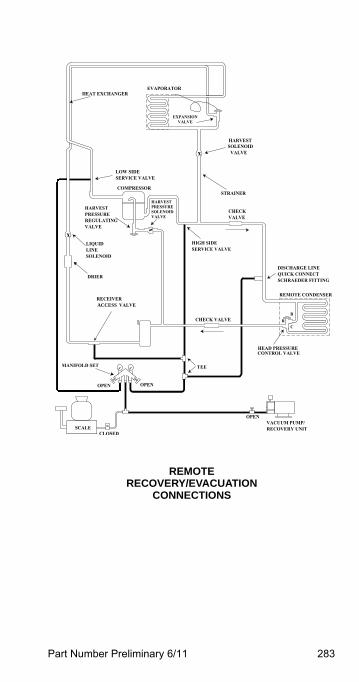
Part Number Preliminary 6/11 283
ACCESS
REMOTERECOVERY/EVACUATION
CONNECTIONS
284 Part Number Preliminary 6/11
Remote Charging Procedures
1. Close the vacuum pump valve and the low side manifold gauge valve.
2. Open the refrigerant cylinder and add the proper refrigerant charge (shown on nameplate) into the system high side (receiver outlet valve and discharge lines quick-connect fitting).
3. If the high side does not take the entire charge, close the high side on the manifold gauge set and start the ice machine. Add the remaining charge through the low side (in vapor form) until the machine is fully charged.
NOTE: If an access valve core removal and installation tool is used on any of the Schraeder valves, reinstall the cores before disconnecting the access tool and hose.
4. Open the high and low side valves on the manifold gauge set. Any refrigerant in the lines will be pulled into the low side of the system.
5. Allow the pressures to equalize while the ice machine is in the freeze cycle.
6. Remove the low side hose from the access valve and install the caps.
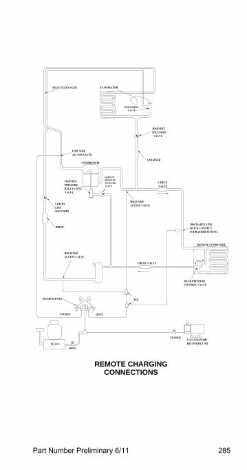
Part Number Preliminary 6/11 285
x
x
x
SCHRAEDER FITTINGQUICK CONNECTDISCHARGE LINE
CONTROL VALVEHEAD PRESSURE
REMOTE CONDENSER
CLOSED
CLOSED
SCALE RECOVERY UNITVACUUM PUMP/
ACCESS VALVERECEIVER
MANIFOLD SET
OPEN
DRIER
SOLENOIDLINE
VALVEREGULATINGPRESSUREHARVEST
LIQUIDACCESS VALVE
CHECK VALVE
TEE
OPEN
C
BR
HIGH SIDE
ACCESS VALVELOW SIDE
COMPRESSOR
HARVESTPRESSURESOLENOIDVALVE
VALVEEXPANSION
VALVECHECK
STRAINER
VALVESOLENOID
HEAT EXCHANGER EVAPORATOR
REMOTE CHARGINGCONNECTIONS
286 Part Number Preliminary 6/11
QUIETQUBE® MODELSDo not purge refrigerant to the atmosphere. Capture refrigerant using recovery equipment. Follow the manufacturer’s recommendations.
ImportantManitowoc Ice assumes no responsibility for the useof contaminated refrigerant. Damage resulting fromthe use of contaminated refrigerant is the soleresponsibility of the servicing company.
ImportantReplace the liquid line drier after recovering therefrigerant and before evacuating and recharging.Use only a Manitowoc (OEM) liquid line filter-drier toprevent voiding the warranty.
! WarningRecovery/evacuation of a QuietQube® remotesystem requires connections at five points forcomplete system recovery/evacuation. Check valvesare located in the ice machine head section and theICVD condensing unit. Five point requiresconnections between the compressor and suctionfilter access valve, receiver access valve and thehigh and low side access valves on the front or rearof the ice machine to recover and evacuate theentire system.
! WarningThe receiver access valve (located in the icemachine head section) must be accessed duringrefrigerant recovery to allow complete removal of therefrigerant charge.
Part Number Preliminary 6/11 287
CONNECTIONSManifold gauge sets must utilize low loss fittings to comply with U.S. Government rules and regulations.
All ICVD condensing units are manufactured with a check valve in the compressor discharge line. The check valve requires an additional connection on the condensing unit during evacuation and recovery procedures. Connection of a manifold gauge set (or a hose with core depressors on both ends) between the suction filter access port and the compressor access valve (located between the compressor and discharge line check valve) is required.
Make these connections:
Ice Machine Head Section - All Models
1. Suction side of the compressor through the suction shut-off valve or suction access valve.
2. Discharge side of the compressor through the liquid line shut-off valve or high side access valve.
3. Receiver access valve, (both receiver service valves on S3070C = fastest recovery time) which evacuates the area between the check valve in the liquid line and the liquid line solenoid valve.
4. Compressor discharge access valve
5. Suction filter access valve.
! WarningRecovery/evacuation of a QuietQube® remotesystem requires connections at five points forcomplete system recovery/evacuation. Check valvesare located in the ice machine head section and theICVD condensing unit. Five point requiresconnections between the compressor and suctionfilter access valve, receiver access valve and thehigh and low side access valves on the front or rearof the ice machine to recover and evacuate theentire system
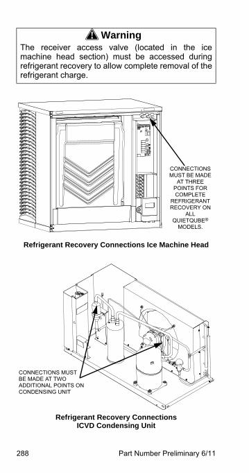
288 Part Number Preliminary 6/11
Refrigerant Recovery Connections ICVD Condensing Unit
! WarningThe receiver access valve (located in the icemachine head section) must be accessed duringrefrigerant recovery to allow complete removal of therefrigerant charge.
CONNECTIONS MUST BE MADE
AT THREE POINTS FOR COMPLETE
REFRIGERANT RECOVERY ON
ALL QUIETQUBE®
MODELS.
Refrigerant Recovery Connections Ice Machine Head
CONNECTIONS MUST BE MADE AT TWO ADDITIONAL POINTS ON CONDENSING UNIT
Part Number Preliminary 6/11 289
RECOVERY/EVACUATION PROCEDURES1. Press the power button to stop the ice machine.
and disconnect all power to the ice machine and condensing unit.
2. Install manifold gauges, charging scale, and recovery unit or two-stage vacuum pump.
3. Open high and low side on the manifold gauge set.
4. Perform recovery or evacuation:
A. Recovery: Operate the recovery unit as directed by the manufacturer’s instructions.
B. Pressure test the system.
C. Evacuation prior to recharging: Evacuate to 500 microns. Then allow the pump to run for an additional hour.
5. Refer to Charging Procedures.
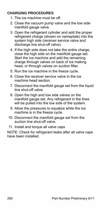
290 Part Number Preliminary 6/11
CHARGING PROCEDURES1. The ice machine must be off.
2. Close the vacuum pump valve and the low side manifold gauge valve.
3. Open the refrigerant cylinder and add the proper refrigerant charge (shown on nameplate) into the system high side (receiver service valve and discharge line shut-off valve).
4. If the high side does not take the entire charge, close the high side on the manifold gauge set. Start the ice machine and add the remaining charge through valves on back of ice making head, or through valves on suction filter.
5. Run the ice machine in the freeze cycle.
6. Close the receiver service valve in the ice machine head section.
7. Disconnect the manifold gauge set from the liquid line shut-off valve.
8. Open the high and low side valves on the manifold gauge set. Any refrigerant in the lines will be pulled into the low side of the system.
9. Allow the pressures to equalize while the ice machine is in the freeze cycle.
10. Disconnect the manifold gauge set from the suction line shut-off valve.
11. Install and torque all valve caps
NOTE: Check for refrigerant leaks after all valve caps have been installed.

Part Number Preliminary 6/11 291
This Page Intentionally Left Blank
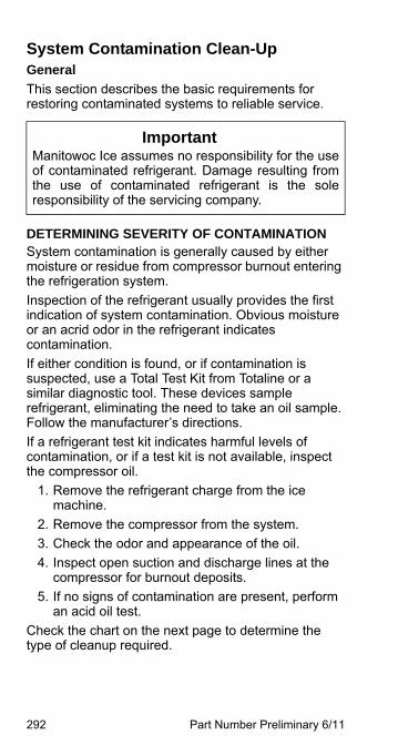
292 Part Number Preliminary 6/11
System Contamination Clean-UpGeneral
This section describes the basic requirements for restoring contaminated systems to reliable service.
DETERMINING SEVERITY OF CONTAMINATIONSystem contamination is generally caused by either moisture or residue from compressor burnout entering the refrigeration system.
Inspection of the refrigerant usually provides the first indication of system contamination. Obvious moisture or an acrid odor in the refrigerant indicates contamination.
If either condition is found, or if contamination is suspected, use a Total Test Kit from Totaline or a similar diagnostic tool. These devices sample refrigerant, eliminating the need to take an oil sample. Follow the manufacturer’s directions.
If a refrigerant test kit indicates harmful levels of contamination, or if a test kit is not available, inspect the compressor oil.
1. Remove the refrigerant charge from the ice machine.
2. Remove the compressor from the system.
3. Check the odor and appearance of the oil.
4. Inspect open suction and discharge lines at the compressor for burnout deposits.
5. If no signs of contamination are present, perform an acid oil test.
Check the chart on the next page to determine the type of cleanup required.
ImportantManitowoc Ice assumes no responsibility for the useof contaminated refrigerant. Damage resulting fromthe use of contaminated refrigerant is the soleresponsibility of the servicing company.
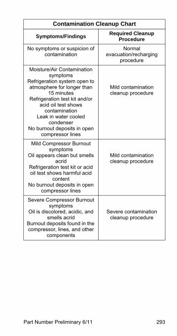
Part Number Preliminary 6/11 293
Contamination Cleanup Chart
Symptoms/FindingsRequired Cleanup
Procedure
No symptoms or suspicion of contamination
Normal evacuation/recharging
procedure
Moisture/Air Contamination symptoms
Refrigeration system open to atmosphere for longer than
15 minutesRefrigeration test kit and/or
acid oil test shows contamination
Leak in water cooled condenser
No burnout deposits in open compressor lines
Mild contamination cleanup procedure
Mild Compressor Burnout symptoms
Oil appears clean but smells acrid
Refrigeration test kit or acid oil test shows harmful acid
contentNo burnout deposits in open
compressor lines
Mild contamination cleanup procedure
Severe Compressor Burnout symptoms
Oil is discolored, acidic, and smells acrid
Burnout deposits found in the compressor, lines, and other
components
Severe contamination cleanup procedure
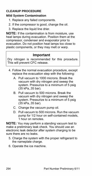
294 Part Number Preliminary 6/11
CLEANUP PROCEDURE
Mild System Contamination
1. Replace any failed components.
2. If the compressor is good, change the oil.
3. Replace the liquid line drier.
NOTE: If the contamination is from moisture, use heat lamps during evacuation. Position them at the compressor, condenser and evaporator prior to evacuation. Do not position heat lamps too close to plastic components, or they may melt or warp.
4. Follow the normal evacuation procedure, except replace the evacuation step with the following:
A. Pull vacuum to 1000 microns. Break the vacuum with dry nitrogen and sweep the system. Pressurize to a minimum of 5 psig (35 kPa,.35 bar).
B. Pull vacuum to 500 microns. Break the vacuum with dry nitrogen and sweep the system. Pressurize to a minimum of 5 psig (35 kPa,.35 bar).
C. Change the vacuum pump oil.
D. Pull vacuum to 500 microns. Run the vacuum pump for 1/2 hour on self-contained models, 1 hour on remotes.
NOTE: You may perform a standing vacuum test to make a preliminary leak check. You should use an electronic leak detector after system charging to be sure there are no leaks.
5. Charge the system with the proper refrigerant to the nameplate charge.
6. Operate the ice machine.
ImportantDry nitrogen is recommended for this procedure.This will prevent CFC release.
Part Number Preliminary 6/11 295
Severe System Contamination
1. Remove the refrigerant charge.
2. Remove the compressor and inspect the refrigeration lines. If burnout deposits are found, install a new harvest valve, replace the manifold strainer, TXV and harvest pressure regulating valve.
3. Wipe away any burnout deposits from suction and discharge lines at compressor.
4. Sweep through the open system with dry nitrogen.
5. Install a new compressor and new start components.
6. Install a suction line filter-drier with acid and moisture removal capability. Place the filter drier as close to the compressor as possible.
7. Install an access valve at the inlet of the suction line drier.
8. Install a new liquid line drier (and suction filter on QuietQube® condensing units).
ImportantRefrigerant sweeps are not recommended, as theyrelease CFCs into the atmosphere.
296 Part Number Preliminary 6/11
9. Follow the normal evacuation procedure, except replace the evacuation step with the following:
A. Pull vacuum to 1000 microns. Break the vacuum with dry nitrogen and sweep the system. Pressurize to a minimum of 5 psig (35 kPa,.35 bar).
B. Change the vacuum pump oil.
C. Pull vacuum to 500 microns. Break the vacuum with dry nitrogen and sweep the system. Pressurize to a minimum of 5 psig (35 kPa,.35 bar).
D. Change the vacuum pump oil.
E. Pull vacuum to 500 microns. Run the vacuum pump for 1/2 hour on self-contained models, 1 hour on remotes.
NOTE: You may perform a standing vacuum test to make a preliminary leak check. You should use an electronic leak detector after system charging to be sure there are no leaks.
10. Charge the system with the proper refrigerant to the nameplate charge.
11. Operate the ice machine for one hour. Then, check the pressure drop across the suction line filter-drier.
A. If the pressure drop is less than 1 psig (7 kPa,.7 bar), the filter-drier should be adequate for complete cleanup.
B. If the pressure drop exceeds 1 psig (7 kPa,.7 bar), change the suction line filter-drier and the liquid line drier. Repeat until the pressure drop is acceptable.
12. Operate the ice machine for 48-72 hours. Then remove the suction line drier and change the liquid line drier.
13. Follow normal evacuation procedures.
ImportantDry nitrogen is recommended for this procedure.This will prevent CFC release.
Part Number Preliminary 6/11 297
REPLACING PRESSURE CONTROLS WITHOUT REMOVING REFRIGERANT CHARGEThis procedure reduces repair time and cost. Use it when any of the following components require replacement, and the refrigeration system is operational and leak-free.
• Fan cycle control (air cooled only)
• Water regulating valve (water cooled only)
• High pressure cut-out control
• Low Pressure cut-out control
• High side service valve
• Low side service valve
1. Disconnect power to the ice machine.
2. Follow all manufacturer’s instructions supplied with the pinch-off tool. Position the pinch-off tool around the tubing as far from the pressure control as feasible. (See the figure on next page.) Clamp down on the tubing until the pinch-off is complete.
3. Cut the tubing of the defective component with a small tubing cutter.
4. Solder the replacement component in place. Allow the solder joint to cool.
5. Remove the pinch-off tool.
6. Re-round the tubing. Position the flattened tubing in the proper hole in the pinch-off tool. Tighten the wing nuts until the block is tight and the tubing is rounded.
NOTE: The pressure controls will operate normally once the tubing is re-rounded. Tubing may not re-round 100%.
ImportantThis is a required in-warranty repair procedure.
! WarningDo not unsolder a defective component. Cut it out ofthe system. Do not remove the pinch-off tool until thenew component is securely in place.
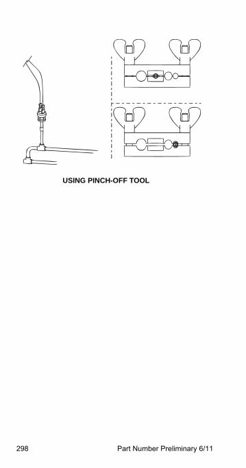
298 Part Number Preliminary 6/11
USING PINCH-OFF TOOL
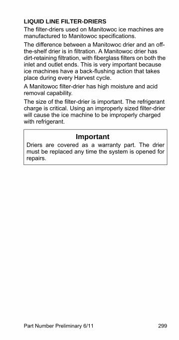
Part Number Preliminary 6/11 299
LIQUID LINE FILTER-DRIERSThe filter-driers used on Manitowoc ice machines are manufactured to Manitowoc specifications.
The difference between a Manitowoc drier and an off-the-shelf drier is in filtration. A Manitowoc drier has dirt-retaining filtration, with fiberglass filters on both the inlet and outlet ends. This is very important because ice machines have a back-flushing action that takes place during every Harvest cycle.
A Manitowoc filter-drier has high moisture and acid removal capability.
The size of the filter-drier is important. The refrigerant charge is critical. Using an improperly sized filter-drier will cause the ice machine to be improperly charged with refrigerant.
ImportantDriers are covered as a warranty part. The driermust be replaced any time the system is opened forrepairs.
300 Part Number Preliminary 6/11
SUCTION FILTERThe suction filter on QuietQube® ICVD condensing units traps particulate only, and do not contain a desiccant. The filter needs replacement when:
1. The pressure drop across the drier exceeds 2 psig.
2. A compressor is replaced.
3. Refrigeration system contains contaminants.
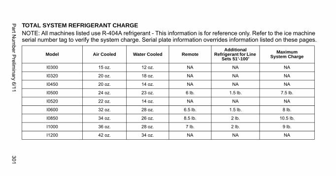
Part N
umber P
relimin
ary 6/11301
TOTAL SYSTEM REFRIGERANT CHARGENOTE: All machines listed use R-404A refrigerant - This information is for reference only. Refer to the ice machine serial number tag to verify the system charge. Serial plate information overrides information listed on these pages.
Model Air Cooled Water Cooled RemoteAdditional
Refrigerant for Line Sets 51’-100’
Maximum System Charge
I0300 15 oz. 12 oz. NA NA NA
I0320 20 oz. 18 oz. NA NA NA
I0450 20 oz. 14 oz. NA NA NA
I0500 24 oz. 23 oz. 6 lb. 1.5 lb. 7.5 lb.
I0520 22 oz. 14 oz. NA NA NA
I0600 32 oz. 28 oz. 6.5 lb. 1.5 lb. 8 lb.
I0850 34 oz. 26 oz. 8.5 lb. 2 lb. 10.5 lb.
I1000 36 oz. 28 oz. 7 lb. 2 lb. 9 lb.
I1200 42 oz. 34 oz. NA NA NA
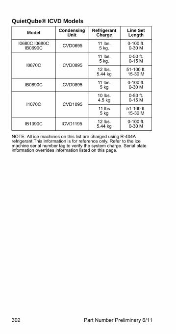
302 Part Number Preliminary 6/11
QuietQube® ICVD Models
NOTE: All ice machines on this list are charged using R-404A refrigerant.This information is for reference only. Refer to the ice machine serial number tag to verify the system charge. Serial plate information overrides information listed on this page.
Model Condensing Unit
Refrigerant Charge
Line SetLength
I0680C I0680C IB0690C ICVD0695 11 lbs.
5 kg.0-100 ft.0-30 M
I0870C ICVD0895
11 lbs.5 kg.
0-50 ft.0-15 M
12 lbs.5.44 kg
51-100 ft.15-30 M
IB0890C ICVD0895 11 lbs.5 kg
0-100 ft.0-30 M
I1070C ICVD1095
10 lbs.4.5 kg
0-50 ft.0-15 M
11 lbs5 kg
51-100 ft.15-30 M
IB1090C ICVD1195 12 lbs.5.44 kg
0-100 ft.0-30 M

Part Number Preliminary 6/11 303
This Page Intentionally Left Blank

304 Part Number Preliminary 6/11

Part Number Preliminary 6/11 305
This Page Intentionally Left Blank

306 Part Number Preliminary 6/11
This Page Intentionally Left Blank
Part Number Preliminary 6/11 307
Charts
Cycle Times/24-Hour Ice Production/Refrigerant Pressure ChartsThese charts are used as guidelines to verify correct ice machine operation.
Accurate collection of data is essential to obtain the correct diagnosis.
• Production and cycle times are for dice cube - Half dice cube cycle times can be 2 - 3 minutes faster, depending on model and ambient temperature.
• Regular cube production derate is 7%.
• Ice production checks that are within 10% of the chart are considered normal. This is due to variances in water and air temperature. Actual temperatures will seldom match the chart exactly.
• Refer to “Symptom #2 - Operational Analysis Table” page 144 for the list of data that must be collected for refrigeration diagnostics. This list includes: before beginning service, ice production check, installation/visual inspection, water system checklist, ice formation pattern, safety limits, comparing evaporator inlet/outlet temperatures, discharge and suction pressure analysis.
• Zero out manifold gauge set before obtaining pressure readings to avoid misdiagnosis.
• Discharge and suction pressure are highest at the beginning of the cycle. Suction pressure will drop throughout the cycle. Verify the pressures are within the range indicated.
• Record beginning of freeze cycle suction pressure one minute after water pump energizes.
• 50Hz dice and half dice production derate is 12%.
• 50Hz regular cube total production derate is 14%.
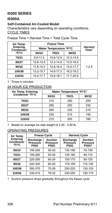
308 Part Number Preliminary 6/11
I0300 SERIES
I0300ASelf-Contained Air-Cooled ModelCharacteristics vary depending on operating conditions.CYCLE TIMES
Freeze Time + Harvest Time = Total Cycle Time
24 HOUR ICE PRODUCTION
OPERATING PRESSURES
Air Temp. Entering
Condenser°F/°C
Freeze TimeHarvest Time1
1 Times in minutes
Water Temperature °F/°C
50/10 70/21 90/32
70/21 9.6-11.5 10.8-12.9 12.3-14.6
1-2.5
80/27 10.6-12.6 12.3-14.6 13.5-16.0
90/32 11.8-14.0 13.9-16.4 15.0-17.7
100/38 13.2-15.7 14.6-17.3 16.2-19.2
110/43 15.0-17.7 15.8-18.7 17.7-20.9
Air Temp. Entering Condenser °F/°C
Water Temperature °F/°C1
1 Based on average ice slab weight of 2.40 - 2.80 lb.
50/10 70/21 90/32
70/21 310 280 250
80/27 285 250 230
90/32 260 225 210
100/38 235 215 195
110/43 210 200 180
Air TempEntering
Condenser°F/°C
Freeze Cycle Harvest Cycle
Discharge Pressure
PSIG
Suction Pressure
PSIG
Discharge Pressure
PSIG
Suction Pressure
PSIG1
1 Suction pressure drops gradually throughout the freeze cycle
50/10 195-245 50-20 135-160 75-100
70/21 195-260 50-20 135-165 80-110
80/27 220-290 60-24 150-170 90-120
90/32 240-320 60-25 170-195 115-135
100/38 285-370 70-28 200-220 130-155
110/43 330-415 78-32 230-250 150-175
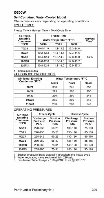
Part Number Preliminary 6/11 309
I0300WSelf-Contained Water-Cooled ModelCharacteristics vary depending on operating conditions.CYCLE TIMES
Freeze Time + Harvest Time = Total Cycle Time
24 HOUR ICE PRODUCTION
OPERATING PRESSURES
Air Temp. Entering
Condenser°F/°C
Freeze TimeHarvest Time1
1 Times in minutes
Water Temperature °F/°C
50/10 70/21 90/32
70/21 10.0-11.9 11.1-13.2 12.3-14.6
1-2.5
80/27 10.2-12.2 11.3-13.4 12.3-14.6
90/32 10.4-12.4 11.8-14.0 12.6-15.0
100/38 10.6-12.6 11.8-14.0 12.6-15.7
110/43 10.8-12.9 11.8-14.0 12.9-15.3
Air Temp. Entering Condenser °F/°C
Water Temperature °F/°C
50/10 70/21 90/32
70/21 300 275 250
80/27 295 270 250
90/32 290 260 245
100/38 285 260 245
110/43 280 260 240
Air TempEntering
Condenser°F/°C
Freeze Cycle Harvest Cycle
Discharge Pressure
PSIG
Suction Pressure
PSIG
Discharge Pressure
PSIG
Suction Pressure
PSIG1
1 Suction pressure drops gradually throughout the freeze cycle2 Water regulating valve set to maintain 220 psig3 Condenser Water Usage = 193 gal/100 lb ice @ 90°/70°F
50/10 220-230 50-25 130-170 75-100
70/21 220-230 50-28 130-170 85-100
80/27 225-245 65-29 130-180 85-110
90/32 230-250 65-30 135-180 85-115
100/38 230-260 70-31 145-190 90-120
110/43 235-260 70-31 150-190 90-120
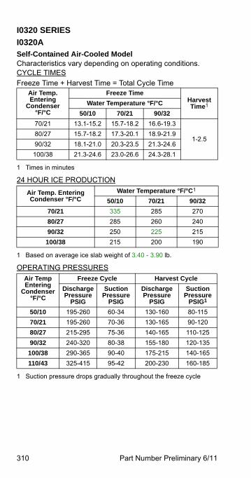
310 Part Number Preliminary 6/11
I0320 SERIES
I0320ASelf-Contained Air-Cooled ModelCharacteristics vary depending on operating conditions.CYCLE TIMESFreeze Time + Harvest Time = Total Cycle Time
24 HOUR ICE PRODUCTION
OPERATING PRESSURES
Air Temp. Entering
Condenser°F/°C
Freeze TimeHarvest Time1
1 Times in minutes
Water Temperature °F/°C
50/10 70/21 90/32
70/21 13.1-15.2 15.7-18.2 16.6-19.3
1-2.580/27 15.7-18.2 17.3-20.1 18.9-21.9
90/32 18.1-21.0 20.3-23.5 21.3-24.6
100/38 21.3-24.6 23.0-26.6 24.3-28.1
Air Temp. Entering Condenser °F/°C
Water Temperature °F/°C1
1 Based on average ice slab weight of 3.40 - 3.90 lb.
50/10 70/21 90/32
70/21 335 285 270
80/27 285 260 240
90/32 250 225 215
100/38 215 200 190
Air TempEntering
Condenser°F/°C
Freeze Cycle Harvest Cycle
Discharge Pressure
PSIG
Suction Pressure
PSIG
Discharge Pressure
PSIG
Suction Pressure
PSIG1
1 Suction pressure drops gradually throughout the freeze cycle
50/10 195-260 60-34 130-160 80-115
70/21 195-260 70-36 130-165 90-120
80/27 215-295 75-36 140-165 110-125
90/32 240-320 80-38 155-180 120-135
100/38 290-365 90-40 175-215 140-165
110/43 325-415 95-42 200-230 160-185

Part Number Preliminary 6/11 311
I0320WSelf-Contained Water-Cooled ModelCharacteristics vary depending on operating conditions.CYCLE TIMESFreeze Time + Harvest Time = Total Cycle Time
24 HOUR ICE PRODUCTION
OPERATING PRESSURES
Air Temp. Around Ice
Machine°F/°C
Freeze TimeHarvest Time1
1 Times in minutes
Water Temperature °F/°C
50/10 70/21 90/32
70/21 13.3-15.5 15.4-17.9 16.6-19.3
1-2.5
80/27 13.8-16.1 16.0-18.6 17.3-20.1
90/32 1.3-16.6 16.6-19.3 18.1-21.0
100/38 14.8-17.2 17.3-20.1 18.9-21.9
110/43 1.4-17.9 18.1-21.0 19.5-22.9
Air Temp. Around Ice Machine °F/°C
Water Temperature °F/°C1
1 Based on average ice slab weight of 3.40-3.90 lb.
50/10 70/21 90/32
70/21 330 290 270
80/27 320 280 260
90/32 310 270 250
100/38 300 260 240
110/43 290 250 230
Air Temp. Around Ice
Machine°F/°C
Freeze Cycle Harvest Cycle
Discharge Pressure
PSIG
Suction Pressure
PSIG
Discharge Pressure
PSIG
Suction Pressure
PSIG 1
1 Suction pressure drops gradually throughout the freeze cycle2 Water regulating valve set to maintain 220 psig3 Condenser Water Usage = 193 gal/100 lb ice @ 90°/70°F
50/10 220-245 60-33 140-185 85-105
70/21 220-250 60-34 140-190 90-120
80/27 235-265 75-38 145-195 90-145
90/32 250-300 80-40 145-200 100-145
100/38 250-360 85-41 175-225 110-150
110/43 250-380 90-42 200-240 120-160
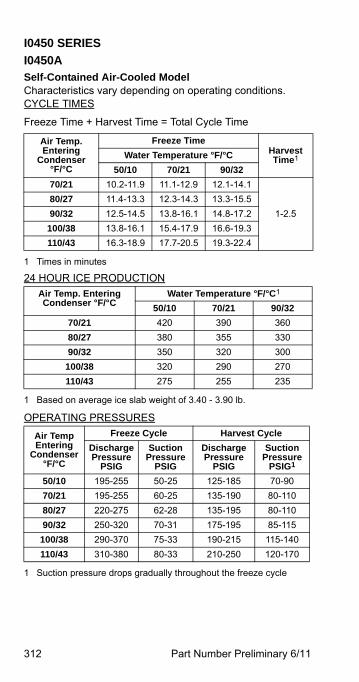
312 Part Number Preliminary 6/11
I0450 SERIES
I0450ASelf-Contained Air-Cooled ModelCharacteristics vary depending on operating conditions.CYCLE TIMES
Freeze Time + Harvest Time = Total Cycle Time
24 HOUR ICE PRODUCTION
OPERATING PRESSURES
Air Temp. Entering
Condenser°F/°C
Freeze TimeHarvest Time1
1 Times in minutes
Water Temperature °F/°C
50/10 70/21 90/32
70/21 10.2-11.9 11.1-12.9 12.1-14.1
1-2.5
80/27 11.4-13.3 12.3-14.3 13.3-15.5
90/32 12.5-14.5 13.8-16.1 14.8-17.2
100/38 13.8-16.1 15.4-17.9 16.6-19.3
110/43 16.3-18.9 17.7-20.5 19.3-22.4
Air Temp. Entering Condenser °F/°C
Water Temperature °F/°C1
1 Based on average ice slab weight of 3.40 - 3.90 lb.
50/10 70/21 90/32
70/21 420 390 360
80/27 380 355 330
90/32 350 320 300
100/38 320 290 270
110/43 275 255 235
Air TempEntering
Condenser°F/°C
Freeze Cycle Harvest Cycle
Discharge Pressure
PSIG
Suction Pressure
PSIG
Discharge Pressure
PSIG
Suction Pressure
PSIG1
1 Suction pressure drops gradually throughout the freeze cycle
50/10 195-255 50-25 125-185 70-90
70/21 195-255 60-25 135-190 80-110
80/27 220-275 62-28 135-195 80-110
90/32 250-320 70-31 175-195 85-115
100/38 290-370 75-33 190-215 115-140
110/43 310-380 80-33 210-250 120-170

Part Number Preliminary 6/11 313
I0450WSelf-Contained Water-Cooled ModelCharacteristics vary depending on operating conditions.CYCLE TIMES
Freeze Time + Harvest Time = Total Cycle Time
24 HOUR ICE PRODUCTION
OPERATING PRESSURES
Air Temp. Entering
Condenser°F/°C
Freeze TimeHarvest Time1
1 Times in minutes
Water Temperature °F/°C
50/10 70/21 90/32
70/21 9.9-11.6 11.1-12.9 12.1-14.1
1-2.5
80/27 10.2-11.9 11.6-13.5 12.5-14.5
90/32 10.3-12.0 12.1-14.1 12.9-15.0
100/38 10.4-12.2 12.5-14.5 13.3-15.5
110/43 10.7-12.5 12.9-15.0 14.3-16.6
Air Temp. Entering Condenser °F/°C
Water Temperature °F/°C1
1 Based on average ice slab weight of 3.40 - 3.90 lb.
50/10 70/21 90/32
70/21 430 390 360
80/27 420 375 350
90/32 415 360 340
100/38 410 350 330
110/43 400 340 310
Air TempEntering
Condenser°F/°C
Freeze Cycle Harvest Cycle
Discharge Pressure
PSIG
Suction Pressure
PSIG
Discharge Pressure
PSIG
Suction Pressure
PSIG1
1 Suction pressure drops gradually throughout the freeze cycle2 Water regulating valve set to maintain 220 psig3 Condenser Water Usage = 169 gal/100 lb ice @ 90°/70°F
50/10 220-230 48-28 130-160 70-95
70/21 220-240 52-28 130-160 75-100
80/27 230-240 55-29 130-160 75-110
90/32 220-240 55-30 135-160 80-115
100/38 235-240 60-30 170-205 80-120
110/43 240-240 60-30 140-205 80-120
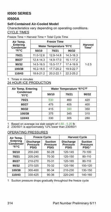
314 Part Number Preliminary 6/11
I0500 SERIES
I0500A Self-Contained Air-Cooled ModelCharacteristics vary depending on operating conditions.CYCLE TIMESFreeze Time + Harvest Time = Total Cycle Time
OPERATING PRESSURES
Air Temp. Entering
Condenser°F/°C
Freeze TimeHarvest Time1
1 Times in minutes24 HOUR ICE PRODUCTION
Water Temperature °F/°C
50/10 70/21 90/32
70/21 11.0-12.6 12.9-14.8 14.3-16.3
1-2.5
80/27 12.4-14.3 14.9-17.0 15.1-17.2
90/32 14.5-16.5 15.5-17.7 17.4-19.9
100/38 16.2-18.5 17.7-20.2 19.9-22.7
110/43 18.6-21.2 20.2-22.1 22.2-25.2
Air Temp. Entering Condenser
°F/°C
Water Temperature °F/°C12
1 Based on average ice slab weight of 4.60 - 5.20 lb2 230/50/1 is approximately 12% lower than 230/60/1
50/10 70/21 90/32
70/21 530 460 420
80/27 475 405 400
90/32 415 390 350
100/38 375 345 310
110/43 330 305 280
Air Temp. Entering
Condenser°F/°C
Freeze Cycle Harvest Cycle
Discharge Pressure
PSIG
Suction Pressure
PSIG
Discharge Pressure
PSIG
Suction Pressure
PSIG1
1 Suction pressure drops gradually throughout the freeze cycle
50/10 200-240 50-28 120-145 70-100
70/21 205-245 70-30 120-150 80-110
80/27 210-270 70-31 120-165 80-110
90/32 270-325 70-32 120-190 100-120
100/38 300-400 90-34 210-230 130-150
110/43 330-425 90-36 220-240 140-160
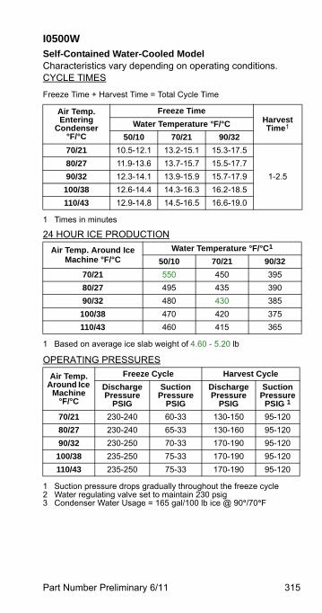
Part Number Preliminary 6/11 315
I0500WSelf-Contained Water-Cooled ModelCharacteristics vary depending on operating conditions.CYCLE TIMES
Freeze Time + Harvest Time = Total Cycle Time
24 HOUR ICE PRODUCTION
OPERATING PRESSURES
Air Temp. Entering
Condenser°F/°C
Freeze TimeHarvest Time1
1 Times in minutes
Water Temperature °F/°C
50/10 70/21 90/32
70/21 10.5-12.1 13.2-15.1 15.3-17.5
1-2.5
80/27 11.9-13.6 13.7-15.7 15.5-17.7
90/32 12.3-14.1 13.9-15.9 15.7-17.9
100/38 12.6-14.4 14.3-16.3 16.2-18.5
110/43 12.9-14.8 14.5-16.5 16.6-19.0
Air Temp. Around Ice Machine °F/°C
Water Temperature °F/°C1
1 Based on average ice slab weight of 4.60 - 5.20 lb
50/10 70/21 90/32
70/21 550 450 395
80/27 495 435 390
90/32 480 430 385
100/38 470 420 375
110/43 460 415 365
Air Temp. Around Ice
Machine°F/°C
Freeze Cycle Harvest Cycle
Discharge Pressure
PSIG
Suction Pressure
PSIG
Discharge Pressure
PSIG
Suction Pressure
PSIG 1
1 Suction pressure drops gradually throughout the freeze cycle2 Water regulating valve set to maintain 230 psig3 Condenser Water Usage = 165 gal/100 lb ice @ 90°/70°F
70/21 230-240 60-33 130-150 95-120
80/27 230-240 65-33 130-160 95-120
90/32 230-250 70-33 170-190 95-120
100/38 235-250 75-33 170-190 95-120
110/43 235-250 75-33 170-190 95-120
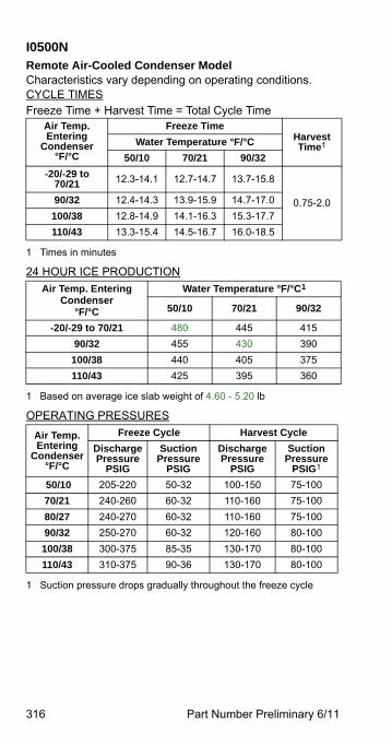
316 Part Number Preliminary 6/11
I0500NRemote Air-Cooled Condenser ModelCharacteristics vary depending on operating conditions.CYCLE TIMESFreeze Time + Harvest Time = Total Cycle Time
24 HOUR ICE PRODUCTION
OPERATING PRESSURES
Air Temp. Entering
Condenser°F/°C
Freeze TimeHarvest Time1
1 Times in minutes
Water Temperature °F/°C
50/10 70/21 90/32
-20/-29 to 70/21 12.3-14.1 12.7-14.7 13.7-15.8
0.75-2.090/32 12.4-14.3 13.9-15.9 14.7-17.0
100/38 12.8-14.9 14.1-16.3 15.3-17.7
110/43 13.3-15.4 14.5-16.7 16.0-18.5
Air Temp. Entering Condenser
°F/°C
Water Temperature °F/°C1
1 Based on average ice slab weight of 4.60 - 5.20 lb
50/10 70/21 90/32
-20/-29 to 70/21 480 445 415
90/32 455 430 390
100/38 440 405 375
110/43 425 395 360
Air Temp. Entering
Condenser°F/°C
Freeze Cycle Harvest Cycle
Discharge Pressure
PSIG
Suction Pressure
PSIG
Discharge Pressure
PSIG
Suction Pressure
PSIG1
1 Suction pressure drops gradually throughout the freeze cycle
50/10 205-220 50-32 100-150 75-100
70/21 240-260 60-32 110-160 75-100
80/27 240-270 60-32 110-160 75-100
90/32 250-270 60-32 120-160 80-100
100/38 300-375 85-35 130-170 80-100
110/43 310-375 90-36 130-170 80-100
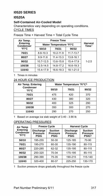
Part Number Preliminary 6/11 317
I0520 SERIES
I0520ASelf-Contained Air-Cooled ModelCharacteristics vary depending on operating conditions.CYCLE TIMES
Freeze Time + Harvest Time = Total Cycle Time
24 HOUR ICE PRODUCTION
OPERATING PRESSURES
Air Temp. Entering
Condenser°F/°C
Freeze TimeHarvest Time1
1 Times in minutes
Water Temperature °F/°C
50/10 70/21 90/32
70/21 8.8-10.3 10.2-11.9 11.7-13.7
1-2.5
80/27 9.9-11.6 11.4-13.3 13.8-16.1
90/32 10.7-12.5 13.6-15.8 15.4-17.9
100/38 12.5-14.5 14.8-17.2 16.6-19.3
110/43 15.4-17.9 16.6-19.3 18.1-21.0
Air Temp. Entering Condenser
°F/°C
Water Temperature °F/°C1
1 Based on average ice slab weight of 3.40 - 3.90 lb
50/10 70/21 90/32
70/21 475 420 370
80/27 430 380 320
90/32 400 325 290
100/38 350 300 270
110/43 290 270 250
Air TempEntering
Condenser°F/°C
Freeze Cycle Harvest Cycle
Discharge Pressure
PSIG
Suction Pressure
PSIG
Discharge Pressure
PSIG
Suction Pressure
PSIG1
1 Suction pressure drops gradually throughout the freeze cycle
50/10 195-255 50-30 125-185 70-90
70/21 195-270 60-30 135-190 80-115
80/27 220-285 62-32 135-195 80-115
90/32 250-320 70-34 175-195 85-115
100/38 290-390 75-35 190-215 115-140
110/43 320-400 80-37 225-250 130-170
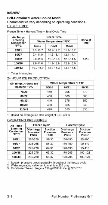
318 Part Number Preliminary 6/11
I0520WSelf-Contained Water-Cooled ModelCharacteristics vary depending on operating conditions.CYCLE TIMES
Freeze Time + Harvest Time = Total Cycle Time
24 HOUR ICE PRODUCTION
OPERATING PRESSURES
Air Temp. Entering
Condenser°F/°C
Freeze TimeHarvest Time1
1 Times in minutes
Water Temperature °F/°C
50/10 70/21 90/32
70/21 9.1-10.7 10.9-12.7 11.7-13.7
1-2.5
80/27 9.4-11.0 11.2-13.1 12.1-14.1
90/32 9.6-11.3 11.6-13.5 12.5-14.5
100/38 9.9-11.6 11.9-13.9 12.9-15.0
110/43 10.2-11.9 12.3-14.3 13.3-15.5
Air Temp. Around Ice Machine °F/°C
Water Temperature °F/°C1
1 Based on average ice slab weight of 3.4 - 3.9 lb
50/10 70/21 90/32
70/21 460 395 370
80/27 450 385 360
90/32 440 375 350
100/38 430 365 340
110/43 420 355 330
Air TempEntering
Condenser°F/°C
Freeze Cycle Harvest Cycle
Discharge Pressure
PSIG
Suction Pressure
PSIG
Discharge Pressure
PSIG
Suction Pressure
PSIG1
1 Suction pressure drops gradually throughout the freeze cycle2 Water regulating valve set to maintain 220 psig3 Condenser Water Usage = 190 gal/100 lb ice @ 90°/70°F
70/21 220-250 52-30 160-190 85-100
80/27 225-265 56-30 170-190 90-110
90/32 225-270 62-31 170-195 95-115
100/38 225-275 65-32 170-205 100-102
110/43 235-280 65-32 170-205 100-120
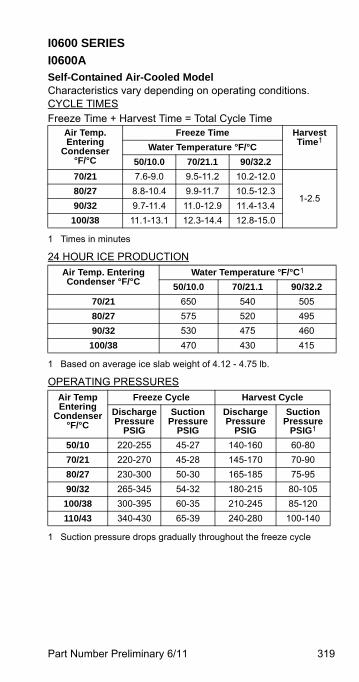
Part Number Preliminary 6/11 319
I0600 SERIES
I0600ASelf-Contained Air-Cooled ModelCharacteristics vary depending on operating conditions.CYCLE TIMESFreeze Time + Harvest Time = Total Cycle Time
24 HOUR ICE PRODUCTION
OPERATING PRESSURES
Air Temp. Entering
Condenser°F/°C
Freeze Time Harvest Time1
1 Times in minutes
Water Temperature °F/°C
50/10.0 70/21.1 90/32.2
70/21 7.6-9.0 9.5-11.2 10.2-12.0
1-2.580/27 8.8-10.4 9.9-11.7 10.5-12.3
90/32 9.7-11.4 11.0-12.9 11.4-13.4
100/38 11.1-13.1 12.3-14.4 12.8-15.0
Air Temp. Entering Condenser °F/°C
Water Temperature °F/°C1
1 Based on average ice slab weight of 4.12 - 4.75 lb.
50/10.0 70/21.1 90/32.2
70/21 650 540 505
80/27 575 520 495
90/32 530 475 460
100/38 470 430 415
Air TempEntering
Condenser°F/°C
Freeze Cycle Harvest Cycle
Discharge Pressure
PSIG
Suction Pressure
PSIG
Discharge Pressure
PSIG
Suction Pressure
PSIG1
1 Suction pressure drops gradually throughout the freeze cycle
50/10 220-255 45-27 140-160 60-80
70/21 220-270 45-28 145-170 70-90
80/27 230-300 50-30 165-185 75-95
90/32 265-345 54-32 180-215 80-105
100/38 300-395 60-35 210-245 85-120
110/43 340-430 65-39 240-280 100-140
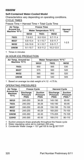
320 Part Number Preliminary 6/11
I0600WSelf-Contained Water-Cooled ModelCharacteristics vary depending on operating conditions.CYCLE TIMESFreeze Time + Harvest Time = Total Cycle Time
24 HOUR ICE PRODUCTION
OPERATING PRESSURES
Air Temp. Around Ice
Machine °F/°C
Freeze TimeHarvest Time1
1 Times in minutes
Water Temperature °F/°C
50/10 70/21 90/32
70/21 7.6-9.0 9.0-10.6 9.7-11.4
1-2.580/27 8.8-10.4 9.1-10.7 9.9-11.7
90/32 9.6-10.6 9.1-10.7 9.9-11.7
100/38 9.1-10.7 9.5-11.2 10.2-12.0
Air Temp. Around Ice Machine °F/°C
Water Temperature °F/°C1
1 Based on average ice slab weight of 4.12 - 4.75 lb.
50/10 70/21 90/32
70/21 650 565 530
80/27 575 560 520
90/32 565 560 520
100/38 560 540 505
Air Temp. Around Ice
Machine°F/°C
Freeze Cycle Harvest Cycle
Discharge Pressure
PSIG
Suction Pressure
PSIG
Discharge Pressure
PSIG
Suction Pressure
PSIG 1
1 Suction pressure drops gradually throughout the freeze cycle2 Water regulating valve set to maintain 240 psig3 Condenser Water Usage = 157 gal/100 lb ice @ 90°/70°F
50/10 240-250 36-26 140-190 65-95
70/21 240-250 36-26 140-190 65-95
80/27 240-250 40-28 150-195 70-100
90/32 245-255 40-29 160-200 70-100
100/38 245-260 40-30 170-205 75-105
110/43 245-265 40-30 180-210 80-110
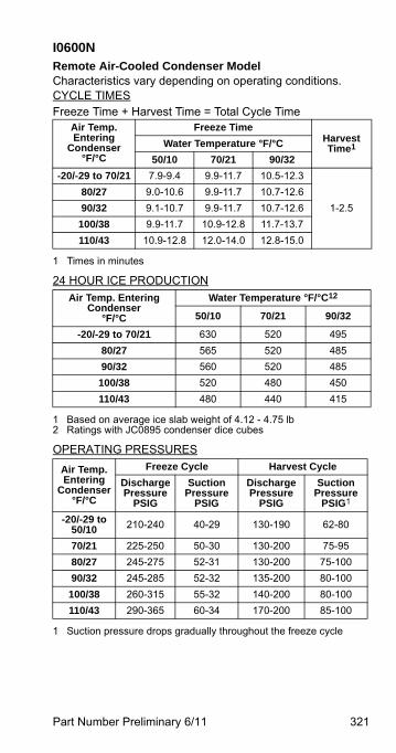
Part Number Preliminary 6/11 321
I0600NRemote Air-Cooled Condenser ModelCharacteristics vary depending on operating conditions.CYCLE TIMESFreeze Time + Harvest Time = Total Cycle Time
24 HOUR ICE PRODUCTION
OPERATING PRESSURES
Air Temp. Entering
Condenser°F/°C
Freeze TimeHarvest Time1
1 Times in minutes
Water Temperature °F/°C
50/10 70/21 90/32
-20/-29 to 70/21 7.9-9.4 9.9-11.7 10.5-12.3
1-2.5
80/27 9.0-10.6 9.9-11.7 10.7-12.6
90/32 9.1-10.7 9.9-11.7 10.7-12.6
100/38 9.9-11.7 10.9-12.8 11.7-13.7
110/43 10.9-12.8 12.0-14.0 12.8-15.0
Air Temp. Entering Condenser
°F/°C
Water Temperature °F/°C12
1 Based on average ice slab weight of 4.12 - 4.75 lb2 Ratings with JC0895 condenser dice cubes
50/10 70/21 90/32
-20/-29 to 70/21 630 520 495
80/27 565 520 485
90/32 560 520 485
100/38 520 480 450
110/43 480 440 415
Air Temp. Entering
Condenser°F/°C
Freeze Cycle Harvest Cycle
Discharge Pressure
PSIG
Suction Pressure
PSIG
Discharge Pressure
PSIG
Suction Pressure
PSIG1
1 Suction pressure drops gradually throughout the freeze cycle
-20/-29 to 50/10 210-240 40-29 130-190 62-80
70/21 225-250 50-30 130-200 75-95
80/27 245-275 52-31 130-200 75-100
90/32 245-285 52-32 135-200 80-100
100/38 260-315 55-32 140-200 80-100
110/43 290-365 60-34 170-200 85-100
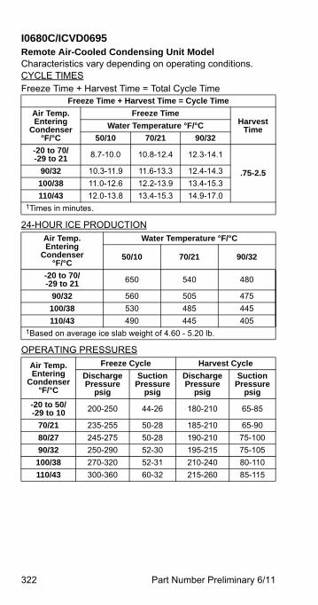
322 Part Number Preliminary 6/11
I0680C/ICVD0695Remote Air-Cooled Condensing Unit ModelCharacteristics vary depending on operating conditions.CYCLE TIMESFreeze Time + Harvest Time = Total Cycle Time
24-HOUR ICE PRODUCTION
OPERATING PRESSURES
Freeze Time + Harvest Time = Cycle Time
Air Temp.Entering
Condenser°F/°C
Freeze TimeHarvest
TimeWater Temperature °F/°C
50/10 70/21 90/32
-20 to 70/-29 to 21 8.7-10.0 10.8-12.4 12.3-14.1
.75-2.590/32 10.3-11.9 11.6-13.3 12.4-14.3
100/38 11.0-12.6 12.2-13.9 13.4-15.3
110/43 12.0-13.8 13.4-15.3 14.9-17.01Times in minutes.
Air Temp.Entering
Condenser°F/°C
Water Temperature °F/°C
50/10 70/21 90/32
-20 to 70/-29 to 21 650 540 480
90/32 560 505 475
100/38 530 485 445
110/43 490 445 4051Based on average ice slab weight of 4.60 - 5.20 lb.
Air Temp.Entering
Condenser°F/°C
Freeze Cycle Harvest Cycle
Discharge Pressure
psig
SuctionPressure
psig
Discharge Pressure
psig
SuctionPressure
psig
-20 to 50/ -29 to 10 200-250 44-26 180-210 65-85
70/21 235-255 50-28 185-210 65-90
80/27 245-275 50-28 190-210 75-100
90/32 250-290 52-30 195-215 75-105
100/38 270-320 52-31 210-240 80-110
110/43 300-360 60-32 215-260 85-115
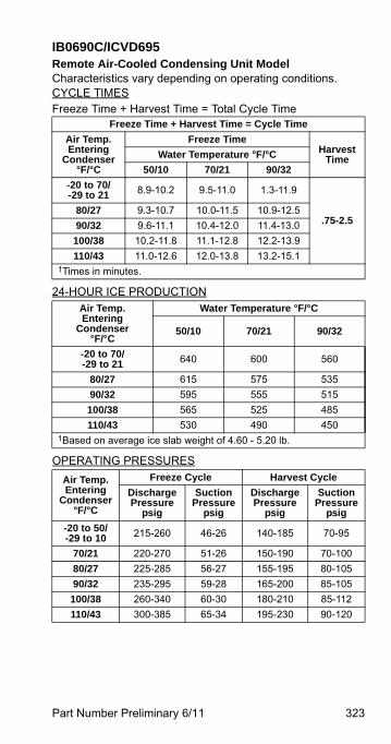
Part Number Preliminary 6/11 323
IB0690C/ICVD695Remote Air-Cooled Condensing Unit ModelCharacteristics vary depending on operating conditions.CYCLE TIMESFreeze Time + Harvest Time = Total Cycle Time
24-HOUR ICE PRODUCTION
OPERATING PRESSURES
Freeze Time + Harvest Time = Cycle Time
Air Temp.Entering
Condenser°F/°C
Freeze TimeHarvest
TimeWater Temperature °F/°C
50/10 70/21 90/32
-20 to 70/-29 to 21 8.9-10.2 9.5-11.0 1.3-11.9
.75-2.580/27 9.3-10.7 10.0-11.5 10.9-12.5
90/32 9.6-11.1 10.4-12.0 11.4-13.0
100/38 10.2-11.8 11.1-12.8 12.2-13.9
110/43 11.0-12.6 12.0-13.8 13.2-15.11Times in minutes.
Air Temp.Entering
Condenser°F/°C
Water Temperature °F/°C
50/10 70/21 90/32
-20 to 70/-29 to 21 640 600 560
80/27 615 575 535
90/32 595 555 515
100/38 565 525 485
110/43 530 490 4501Based on average ice slab weight of 4.60 - 5.20 lb.
Air Temp.Entering
Condenser°F/°C
Freeze Cycle Harvest Cycle
Discharge Pressure
psig
SuctionPressure
psig
Discharge Pressure
psig
SuctionPressure
psig
-20 to 50/ -29 to 10 215-260 46-26 140-185 70-95
70/21 220-270 51-26 150-190 70-100
80/27 225-285 56-27 155-195 80-105
90/32 235-295 59-28 165-200 85-105
100/38 260-340 60-30 180-210 85-112
110/43 300-385 65-34 195-230 90-120

324 Part Number Preliminary 6/11
I0850 SERIES
I0850ASelf-Contained Air-Cooled ModelCharacteristics vary depending on operating conditions.CYCLE TIMES
Freeze Time + Harvest Time = Total Cycle Time
24 HOUR ICE PRODUCTION
OPERATING PRESSURES
Air Temp. Entering
Condenser°F/°C
Freeze TimeHarvest Time1
1 Times in minutes
Water Temperature °F/°C
50/10 70/21 90/32
70/21 9.0-10.4 9.8-11.2 10.5-12.1
1-2.5
80/27 10.1-11.6 10.8-12.4 11.6-13.4
90/32 11.3-13.0 12.9-14.8 12.9-14.8
100/38 12.9-14.8 13.7-15.7 14.6-16.7
110/43 14.9-17.0 15.8-18.0 16.5-18.8
Air Temp. Entering Condenser °F/°C
Water Temperature °F/°C1
1 Based on average ice slab weight of 5.75 - 6.50 lb.
50/10 70/21 90/32
70/21 785 735 690
80/27 715 675 630
90/32 645 575 575
100/38 575 545 515
110/43 505 480 460
Air Temp. Entering
Condenser°F/°C
Freeze Cycle Harvest Cycle
Discharge Pressure
PSIG
Suction Pressure
PSIG
Discharge Pressure
PSIG
Suction Pressure
PSIG1
1 Suction pressure drops gradually throughout the freeze cycle
50/10 200-255 45-25 125-140 70-90
70/21 200-255 45-26 125-140 75-90
80/27 250-275 50-28 130-160 80-100
90/32 315-260 55-30 160-175 90-115
100/38 330-385 75-34 200-225 130-160
110/43 335-400 78-35 200-230 130-160
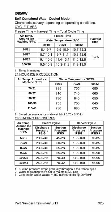
Part Number Preliminary 6/11 325
I0850WSelf-Contained Water-Cooled ModelCharacteristics vary depending on operating conditions.CYCLE TIMESFreeze Time + Harvest Time = Total Cycle Time
24 HOUR ICE PRODUCTION
OPERATING PRESSURES
Air Temp. Around Ice
Machine °F/°C
Freeze TimeHarvest Time1
1 Times in minutes
Water Temperature °F/°C
50/10 70/21 90/32
70/21 8.4-9.7 9.5-10.9 10.7-12.3
1-2.580/27 8.7-10.1 9.7-11.1 10.8-12.6
90/32 9.1-10.5 11.4-13.1 11.0-12.8
100/38 9.5-10.9 10.3-11.9 11.3-13.0
Air Temp. Around Ice Machine °F/°C
Water Temperature °F/°C1
1 Based on average ice slab weight of 5.75 - 6.50 lb.
50/10 70/21 90/32
70/21 835 755 680
80/27 810 740 665
90/32 780 640 655
100/38 755 700 645
110/43 730 680 635
Air Temp. Around Ice
Machine°F/°C
Freeze Cycle Harvest Cycle
Discharge Pressure
PSIG
Suction Pressure
PSIG
Discharge Pressure
PSIG
Suction Pressure
PSIG 1
1 Suction pressure drops gradually throughout the freeze cycle2 Water regulating valve set to maintain 230 psig3 Condenser Water Usage = 150 gal/100 lb ice @ 90°/70°F
50/10 230-240 45-28 135-160 70-85
70/21 230-240 60-28 135-160 70-85
80/27 230-240 65-28 135-160 70-85
90/32 240-250 65-28 135-160 70-90
100/38 240-255 70-30 140-160 75-95
110/43 240-265 70-32 140-160 75-95
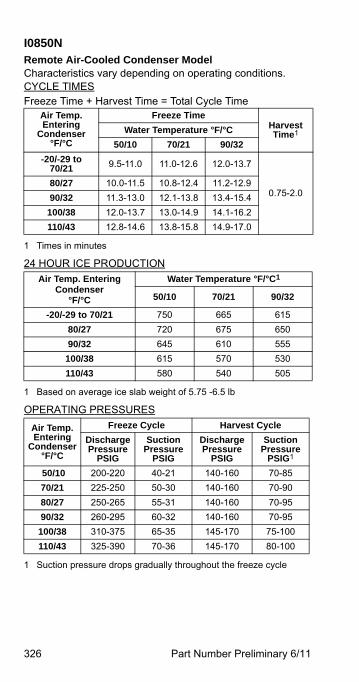
326 Part Number Preliminary 6/11
I0850N Remote Air-Cooled Condenser ModelCharacteristics vary depending on operating conditions.CYCLE TIMESFreeze Time + Harvest Time = Total Cycle Time
24 HOUR ICE PRODUCTION
OPERATING PRESSURES
Air Temp. Entering
Condenser°F/°C
Freeze TimeHarvest Time1
1 Times in minutes
Water Temperature °F/°C
50/10 70/21 90/32
-20/-29 to 70/21 9.5-11.0 11.0-12.6 12.0-13.7
0.75-2.080/27 10.0-11.5 10.8-12.4 11.2-12.9
90/32 11.3-13.0 12.1-13.8 13.4-15.4
100/38 12.0-13.7 13.0-14.9 14.1-16.2
110/43 12.8-14.6 13.8-15.8 14.9-17.0
Air Temp. Entering Condenser
°F/°C
Water Temperature °F/°C1
1 Based on average ice slab weight of 5.75 -6.5 lb
50/10 70/21 90/32
-20/-29 to 70/21 750 665 615
80/27 720 675 650
90/32 645 610 555
100/38 615 570 530
110/43 580 540 505
Air Temp. Entering
Condenser°F/°C
Freeze Cycle Harvest Cycle
Discharge Pressure
PSIG
Suction Pressure
PSIG
Discharge Pressure
PSIG
Suction Pressure
PSIG1
1 Suction pressure drops gradually throughout the freeze cycle
50/10 200-220 40-21 140-160 70-85
70/21 225-250 50-30 140-160 70-90
80/27 250-265 55-31 140-160 70-95
90/32 260-295 60-32 140-160 70-95
100/38 310-375 65-35 145-170 75-100
110/43 325-390 70-36 145-170 80-100
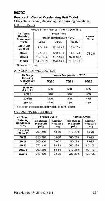
Part Number Preliminary 6/11 327
I0870CRemote Air-Cooled Condensing Unit ModelCharacteristics vary depending on operating conditions.CYCLE TIMES
24-HOUR ICE PRODUCTION
OPERATING PRESSURES
Freeze Time + Harvest Time = Cycle Time
Air Temp.Entering
Condenser°F/°C
Freeze TimeHarvest
TimeWater Temperature °F/°C
50/10 70/21 90/32
-20 to 70/-29 to 21 11.0-12.6 12.1-13.8 13.4-15.4
.75-2.590/32 12.5-14.4 12.8-14.6 14.9-17.0
100/38 13.6-15.5 14.7-16.9 1539-18.2
110/43 14.9-16.9 15.8-18.0 16.9-19.31Times in minutes.
Air Temp.Entering
Condenser°F/°C
Water Temperature °F/°C
50/10 70/21 90/32
-20 to 70/-29 to 21 665 610 555
90/32 590 580 505
100/38 550 510 475
110/43 510 480 4501Based on average ice slab weight of 5.75-6.50 lb.
Air Temp.Entering
Condenser°F/°C
Freeze Cycle Harvest Cycle
Discharge Pressure
psig
SuctionPressure
psig
Discharge Pressure
psig
SuctionPressure
psig
-20 to 50/ -29 to 10 200-250 50-30 170-200 65-75
70/21 250-290 60-30 180-210 75-95
80/27 260-300 60-31 190-220 75-95
90/32 270-310 60-33 200-230 80-100
100/38 300-380 80-34 210-250 90-110
110/43 310-390 80-35 220-260 105-130
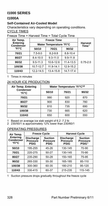
328 Part Number Preliminary 6/11
I1000 SERIES
I1000ASelf-Contained Air-Cooled ModelCharacteristics vary depending on operating conditions.CYCLE TIMESFreeze Time + Harvest Time = Total Cycle Time
24 HOUR ICE PRODUCTION
OPERATING PRESSURES
Air Temp. Entering
Condenser°F/°C
Freeze TimeHarvest Time1
1 Times in minutes
Water Temperature °F/°C
50/10 70/21 90/32
70/21 7.5-9.0 8.2-9.8 8.8-10.4
0.75-2.0
80/27 8.4-10.0 9.3-11.0 9.9-11.8
90/32 9.5-11.3 10.6-12.6 11.4-13.5
100/38 10.7-12.7 11.9-14.1 12.9-15.2
110/43 12.2-14.5 13.4-15.8 14.7-17.4
Air Temp. Entering Condenser
°F/°C
Water Temperature °F/°C12
1 Based on average ice slab weight of 6.2 -7.2 lb2 230/50/1 is approximately 12% lower than 230/60/1
50/10 70/21 90/32
70/21 990 920 870
80/27 900 830 780
90/32 810 735 690
100/38 730 665 620
110/43 650 600 550
Air Temp. Entering
Condenser°F/°C
Freeze Cycle Harvest Cycle
Discharge Pressure
PSIG
Suction Pressure
PSIG
Discharge Pressure
PSIG
Suction Pressure
PSIG1
1 Suction pressure drops gradually throughout the freeze cycle
50/10 195-255 45-26 130-145 70-90
70/21 220-275 50-27 130-145 70-90
80/27 235-290 50-28 150-165 75-95
90/32 265-330 55-30 165-185 85-110
100/38 300-360 60-35 180-210 95-120
110/43 330-415 60-37 215-235 115-145
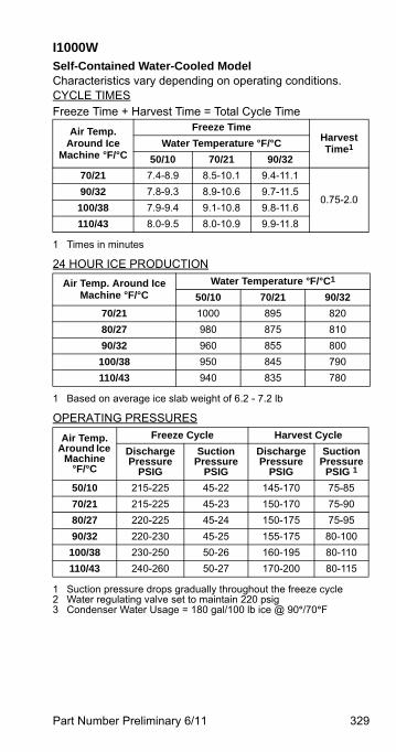
Part Number Preliminary 6/11 329
I1000WSelf-Contained Water-Cooled ModelCharacteristics vary depending on operating conditions.CYCLE TIMESFreeze Time + Harvest Time = Total Cycle Time
24 HOUR ICE PRODUCTION
OPERATING PRESSURES
Air Temp. Around Ice
Machine °F/°C
Freeze TimeHarvest Time1
1 Times in minutes
Water Temperature °F/°C
50/10 70/21 90/32
70/21 7.4-8.9 8.5-10.1 9.4-11.1
0.75-2.090/32 7.8-9.3 8.9-10.6 9.7-11.5
100/38 7.9-9.4 9.1-10.8 9.8-11.6
110/43 8.0-9.5 8.0-10.9 9.9-11.8
Air Temp. Around Ice Machine °F/°C
Water Temperature °F/°C1
1 Based on average ice slab weight of 6.2 - 7.2 lb
50/10 70/21 90/32
70/21 1000 895 820
80/27 980 875 810
90/32 960 855 800
100/38 950 845 790
110/43 940 835 780
Air Temp. Around Ice
Machine°F/°C
Freeze Cycle Harvest Cycle
Discharge Pressure
PSIG
Suction Pressure
PSIG
Discharge Pressure
PSIG
Suction Pressure
PSIG 1
1 Suction pressure drops gradually throughout the freeze cycle2 Water regulating valve set to maintain 220 psig3 Condenser Water Usage = 180 gal/100 lb ice @ 90°/70°F
50/10 215-225 45-22 145-170 75-85
70/21 215-225 45-23 150-170 75-90
80/27 220-225 45-24 150-175 75-95
90/32 220-230 45-25 155-175 80-100
100/38 230-250 50-26 160-195 80-110
110/43 240-260 50-27 170-200 80-115
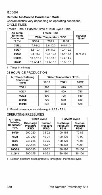
330 Part Number Preliminary 6/11
I1000NRemote Air-Cooled Condenser ModelCharacteristics vary depending on operating conditions.CYCLE TIMESFreeze Time + Harvest Time = Total Cycle Time
24 HOUR ICE PRODUCTION
OPERATING PRESSURES
Air Temp. Entering
Condenser°F/°C
Freeze TimeHarvest Time1
1 Times in minutes
Water Temperature °F/°C
50/10 70/21 90/32
70/21 7.7-9.2 8.6-10.3 9.5-11.3
0.75-2.0
80/27 8.5-10.1 9.5-11.3 10.4-12.3
90/32 9.5-11.3 10.6-12.6 11.4-13.5
100/38 10.7-12.7 11.6-13.8 12.4-14.7
110/43 12.2-14.5 12.7-15.0 13.6-16.1
Air Temp. Entering Condenser
°F/°C
Water Temperature °F/°C1
1 Based on average ice slab weight of 6.2 - 7.2 lb
50/10 70/21 90/32
70/21 960 870 800
80/27 880 800 740
90/32 800 725 680
100/38 720 670 630
110/43 640 620 580
Air Temp. Entering
Condenser°F/°C
Freeze Cycle Harvest Cycle
Discharge Pressure
PSIG
Suction Pressure
PSIG
Discharge Pressure
PSIG
Suction Pressure
PSIG1
1 Suction pressure drops gradually throughout the freeze cycle
50/10 200-220 35-22 100-165 70-85
70/21 220-260 40-24 100-170 70-90
80/27 245-285 45-25 100-170 70-95
90/32 250-300 50-27 100-170 70-95
100/38 285-330 60-32 130-180 75-100
110/43 300-375 60-32 130-190 80-100
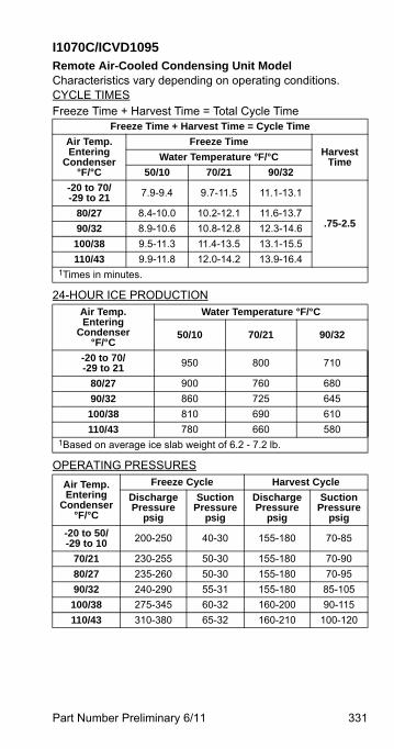
Part Number Preliminary 6/11 331
I1070C/ICVD1095Remote Air-Cooled Condensing Unit ModelCharacteristics vary depending on operating conditions.CYCLE TIMESFreeze Time + Harvest Time = Total Cycle Time
24-HOUR ICE PRODUCTION
OPERATING PRESSURES
Freeze Time + Harvest Time = Cycle Time
Air Temp.Entering
Condenser°F/°C
Freeze TimeHarvest
TimeWater Temperature °F/°C
50/10 70/21 90/32
-20 to 70/-29 to 21 7.9-9.4 9.7-11.5 11.1-13.1
.75-2.580/27 8.4-10.0 10.2-12.1 11.6-13.7
90/32 8.9-10.6 10.8-12.8 12.3-14.6
100/38 9.5-11.3 11.4-13.5 13.1-15.5
110/43 9.9-11.8 12.0-14.2 13.9-16.41Times in minutes.
Air Temp.Entering
Condenser°F/°C
Water Temperature °F/°C
50/10 70/21 90/32
-20 to 70/-29 to 21 950 800 710
80/27 900 760 680
90/32 860 725 645
100/38 810 690 610
110/43 780 660 5801Based on average ice slab weight of 6.2 - 7.2 lb.
Air Temp.Entering
Condenser°F/°C
Freeze Cycle Harvest Cycle
Discharge Pressure
psig
SuctionPressure
psig
Discharge Pressure
psig
SuctionPressure
psig
-20 to 50/ -29 to 10 200-250 40-30 155-180 70-85
70/21 230-255 50-30 155-180 70-90
80/27 235-260 50-30 155-180 70-95
90/32 240-290 55-31 155-180 85-105
100/38 275-345 60-32 160-200 90-115
110/43 310-380 65-32 160-210 100-120
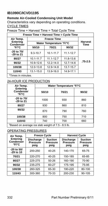
332 Part Number Preliminary 6/11
IB1090C/ICVD1195Remote Air-Cooled Condensing Unit ModelCharacteristics vary depending on operating conditions.CYCLE TIMESFreeze Time + Harvest Time = Total Cycle Time
24-HOUR ICE PRODUCTION
OPERATING PRESSURES
Freeze Time + Harvest Time = Cycle Time
Air Temp.Entering
Condenser°F/°C
Freeze TimeHarvest
TimeWater Temperature °F/°C
50/10 70/21 90/32
-20 to 70/-29 to 21 9.3-10.7 10.1-11.7 11.1-12.7
.75-2.580/27 10.1-11.7 11.1-12.7 11.8-13.6
90/32 10.9-12.6 12.2-14.0 12.7-14.6
100/38 12.0-13.8 12.9-14.8 13.7-15.7
110/43 13.1-15.0 13.9-16.0 14.9-17.11Times in minutes.
Air Temp.Entering
Condenser°F/°C
Water Temperature °F/°C
50/10 70/21 90/32
-20 to 70/-29 to 21 1000 930 860
80/27 930 860 810
90/32 870 790 760
100/38 800 750 710
110/43 740 700 6601Based on average ice slab weight of 7.5 - 8.5 lb.
Air Temp.Entering
Condenser°F/°C
Freeze Cycle Harvest Cycle
Discharge Pressure
psig
SuctionPressure
psig
Discharge Pressure
psig
SuctionPressure
psig
-20 to 50/ -29 to 10 200-250 40-25 140-170 65-75
70/21 220-270 40-25 150-185 65-85
80/27 225-275 50-26 160-190 70-90
90/32 235-275 60-27 175-195 75-95
100/38 260-325 65-30 190-220 80-100
110/43 300-360 70-33 200-230 90-105
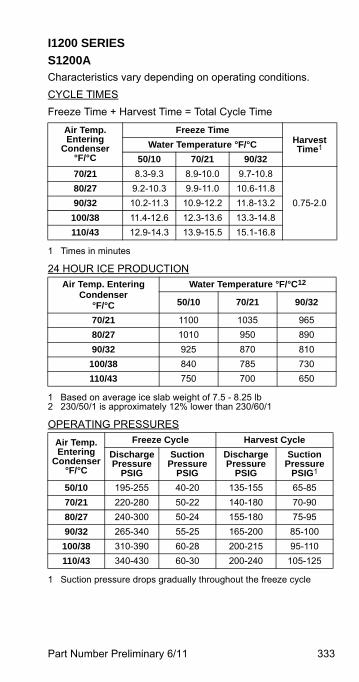
Part Number Preliminary 6/11 333
I1200 SERIES
S1200A Characteristics vary depending on operating conditions.
CYCLE TIMES
Freeze Time + Harvest Time = Total Cycle Time
24 HOUR ICE PRODUCTION
OPERATING PRESSURES
Air Temp. Entering
Condenser°F/°C
Freeze TimeHarvest Time1
1 Times in minutes
Water Temperature °F/°C
50/10 70/21 90/32
70/21 8.3-9.3 8.9-10.0 9.7-10.8
0.75-2.0
80/27 9.2-10.3 9.9-11.0 10.6-11.8
90/32 10.2-11.3 10.9-12.2 11.8-13.2
100/38 11.4-12.6 12.3-13.6 13.3-14.8
110/43 12.9-14.3 13.9-15.5 15.1-16.8
Air Temp. Entering Condenser
°F/°C
Water Temperature °F/°C12
1 Based on average ice slab weight of 7.5 - 8.25 lb2 230/50/1 is approximately 12% lower than 230/60/1
50/10 70/21 90/32
70/21 1100 1035 965
80/27 1010 950 890
90/32 925 870 810
100/38 840 785 730
110/43 750 700 650
Air Temp. Entering
Condenser°F/°C
Freeze Cycle Harvest Cycle
Discharge Pressure
PSIG
Suction Pressure
PSIG
Discharge Pressure
PSIG
Suction Pressure
PSIG1
1 Suction pressure drops gradually throughout the freeze cycle
50/10 195-255 40-20 135-155 65-85
70/21 220-280 50-22 140-180 70-90
80/27 240-300 50-24 155-180 75-95
90/32 265-340 55-25 165-200 85-100
100/38 310-390 60-28 200-215 95-110
110/43 340-430 60-30 200-240 105-125
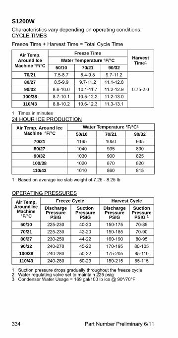
334 Part Number Preliminary 6/11
S1200WCharacteristics vary depending on operating conditions.CYCLE TIMES
Freeze Time + Harvest Time = Total Cycle Time
24 HOUR ICE PRODUCTION
OPERATING PRESSURES
Air Temp. Around Ice
Machine °F/°C
Freeze TimeHarvest Time1
1 Times in minutes
Water Temperature °F/°C
50/10 70/21 90/32
70/21 7.5-8.7 8.4-9.8 9.7-11.2
0.75-2.0
80/27 8.5-9.9 9.7-11.2 11.1-12.8
90/32 8.6-10.0 10.1-11.7 11.2-12.9
100/38 8.7-10.1 10.5-12.2 11.2-13.0
110/43 8.8-10.2 10.6-12.3 11.3-13.1
Air Temp. Around Ice Machine °F/°C
Water Temperature °F/°C1
1 Based on average ice slab weight of 7.25 - 8.25 lb
50/10 70/21 90/32
70/21 1165 1050 935
80/27 1040 935 830
90/32 1030 900 825
100/38 1020 870 820
110/43 1010 860 815
Air Temp. Around Ice
Machine°F/°C
Freeze Cycle Harvest Cycle
Discharge Pressure
PSIG
Suction Pressure
PSIG
Discharge Pressure
PSIG
Suction Pressure
PSIG 1
1 Suction pressure drops gradually throughout the freeze cycle2 Water regulating valve set to maintain 225 psig3 Condenser Water Usage = 169 gal/100 lb ice @ 90°/70°F
50/10 225-230 40-20 150-175 70-85
70/21 225-230 42-20 150-185 70-90
80/27 230-250 44-22 160-190 80-95
90/32 240-270 45-22 170-195 80-105
100/38 240-280 50-22 175-205 85-110
110/43 240-280 50-23 180-215 85-115
Part Number Preliminary 6/11 335
Diagrams
Wiring DiagramsThe following pages contain electrical wiring diagrams. Be sure you are referring to the correct diagram for the ice machine you are servicing.
Some components are wired differently on energy efficient machines. Please verify your serial number (page 18) to reference the correct diagrams.
WIRING DIAGRAM LEGENDThe following symbols are used on all of the wiring diagrams:
* Internal Compressor Overload(Some models have external compressor overloads)
** Fan Motor Run Capacitor(Some models do not incorporate fan motor run capacitor)
( ) Wire Number Designation(The number is marked at each end of the wire)
—>>— Multi-Pin Connection(Electrical Box Side) —>>— (Compressor Compartment Side)
! WarningAlways disconnect power before working onelectrical circuitry.
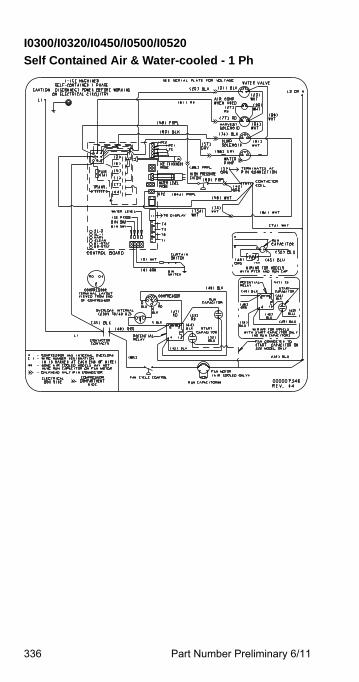
336 Part Number Preliminary 6/11
I0300/I0320/I0450/I0500/I0520
Self Contained Air & Water-cooled - 1 Ph
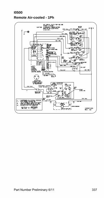
Part Number Preliminary 6/11 337
I0500
Remote Air-cooled - 1Ph
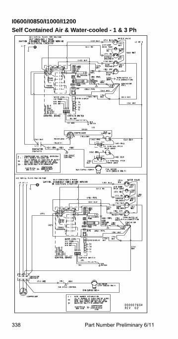
338 Part Number Preliminary 6/11
I0600/I0850/I1000/I1200
Self Contained Air & Water-cooled - 1 & 3 Ph
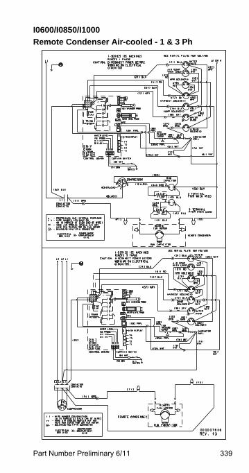
Part Number Preliminary 6/11 339
I0600/I0850/I1000
Remote Condenser Air-cooled - 1 & 3 Ph
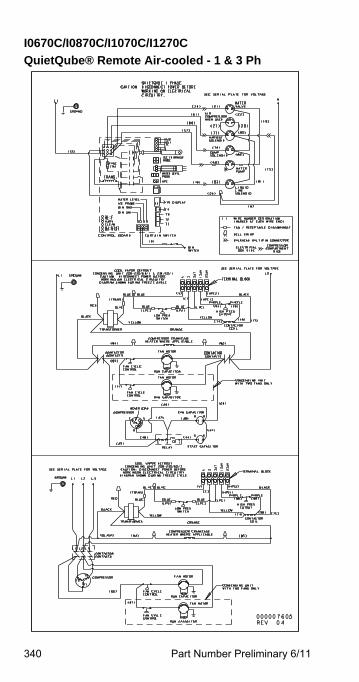
340 Part Number Preliminary 6/11
I0670C/I0870C/I1070C/I1270C
QuietQube® Remote Air-cooled - 1 & 3 Ph
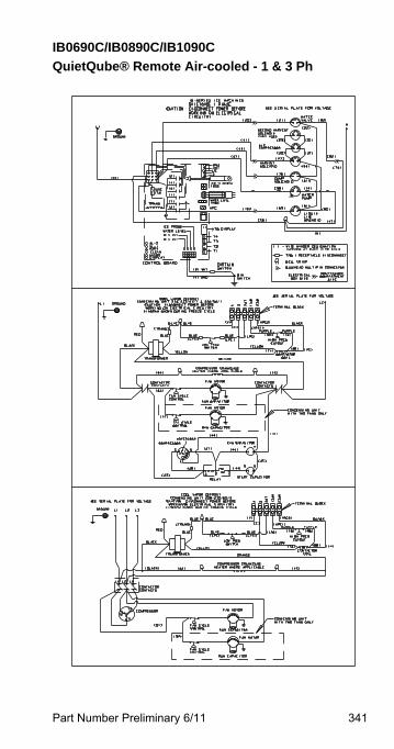
Part Number Preliminary 6/11 341
IB0690C/IB0890C/IB1090C
QuietQube® Remote Air-cooled - 1 & 3 Ph
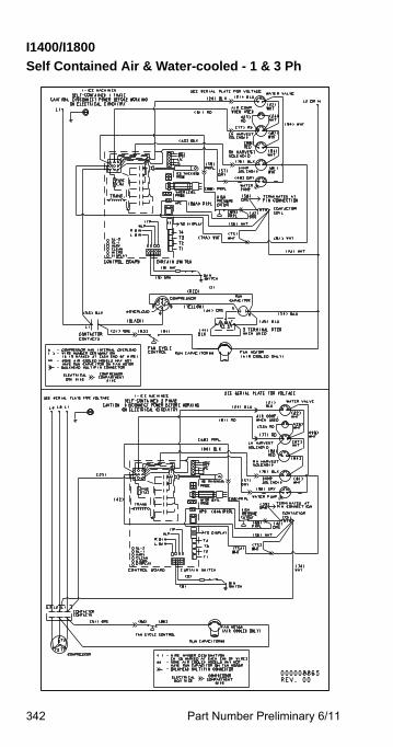
342 Part Number Preliminary 6/11
I1400/I1800
Self Contained Air & Water-cooled - 1 & 3 Ph
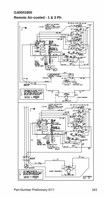
Part Number Preliminary 6/11 343
I1400/I1800
Remote Air-cooled - 1 & 3 Ph
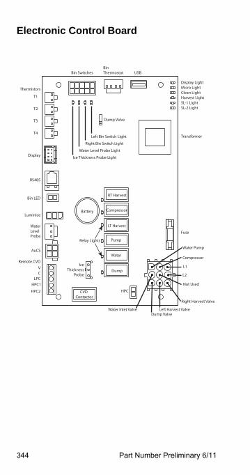
344 Part Number Preliminary 6/11
Electronic Control Board
RT Harvest
Compressor
LT Harvest
Pump
Water
Dump
Display LightMicro LightClean LightHarvest LightSL-1 LightSL-2 Light
Fuse
Thermistors
T1
T2
T3
T4
Display
RS485
Bin LED
WaterLevelProbe
AuCS
Remote CVD
LuminIce
Transformer
Battery
Bin SwitchesBin Thermostat USB
Ice Thickness Probe Light
Water Level Probe Light
Right Bin Switch Light
Left Bin Switch Light
Dump Valve
HPC
IceThickness
Probe
Water Pump
Compressor
L1
Not Used
L2
Water Inlet Valve
Right Harvest Valve
Left Harvest ValveDump Valve
Relay Lights
VC
LPCHPC1
HPC2 CVD Contactor
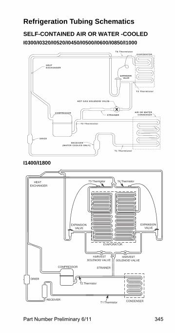
Part Number Preliminary 6/11 345
Refrigeration Tubing Schematics
SELF-CONTAINED AIR OR WATER -COOLED
I0300/I0320/I0520/I0450/I0500/I0600/I0850/I1000
I1400/I1800
X
RECEIVER (WATER COOLED ONLY)
DRIER
COMPRESSORSTRAINER CONDENSER
AIR OR WATER
HOT GAS SOLENOID VALVE
EXPANSION VALVE
EVAPORATOR
HEATEXCHANGER
T1 Thermistor
T4 Thermistor
T3 Thermistor
T2 Thermistorxx
CONDENSER
COMPRESSOR
HEATEXCHANGER
RECEIVER
DRIER
EVAPORATOR
HARVESTSOLENOID VALVE
STRAINER
HARVESTSOLENOID VALVE
EXPANSION VALVE
EXPANSION VALVE
T2 Thermistor
T3 Thermistor T4 Thermistor
T1 Thermistor
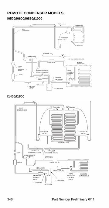
346 Part Number Preliminary 6/11
REMOTE CONDENSER MODELS
I0500/I0600/I0850/I1000
I1400/I1800
RECEIVERACCESSRECEIVER
VALVE
DRIER
CHECK VALVE
HEADPRESSURECONTROL VALVE
BR
C
H.P.R. SOLENOIDVALVE
HARVEST PRESSUREREGULATING VALVE
CHECK VALVE
STRAINER
COMPRESSOR
HOT GAS SOLENOID VALVE
CONDENSERREMOTE
EXPANSION VALVE
EVAPORATOR
HEATEXCHANGER
SOLENOIDLINELIQUID
VALVE
X
X
T2 Thermistor
T4 Thermistor
T1 Thermistor
T3 Thermistor
x
xx
REMOTECONDENSER
COMPRESSOR
HEATEXCHANGER
RECEIVER
DRIER
EXPANSION VALVE
EVAPORATOR
HPR VALVE
LLSV
CHECK VALVE
CHECK VALVE
HARVESTSOLENOID VALVE
STRAINER
HARVESTSOLENOID VALVE
HEADPRESSURECONTROL
VALVE
EXPANSION VALVE
RECEIVERACCESSVALVE
T2 Thermistor
T3 Thermistor
T1 Thermistor
T4 Thermistor
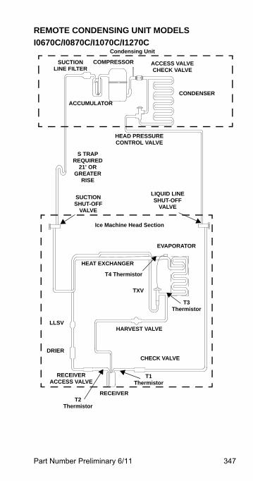
Part Number Preliminary 6/11 347
REMOTE CONDENSING UNIT MODELS
I0670C/I0870C/I1070C/I1270C
RECEIVER
RECEIVER ACCESS VALVE
LLSV
SUCTIONSHUT-OFF
VALVE
HEAT EXCHANGER
CHECK VALVE
HEAD PRESSURECONTROL VALVE
ACCUMULATOR
TXV
HARVEST VALVE
COMPRESSOR
EVAPORATOR
LIQUID LINESHUT-OFF
VALVE
CONDENSER
S TRAP REQUIRED
21’ OR GREATER
RISE
DRIER
SUCTIONLINE FILTER
Ice Machine Head Section
Condensing Unit
ACCESS VALVECHECK VALVE
T1 Thermistor
T2 Thermistor
T4 Thermistor
T3 Thermistor
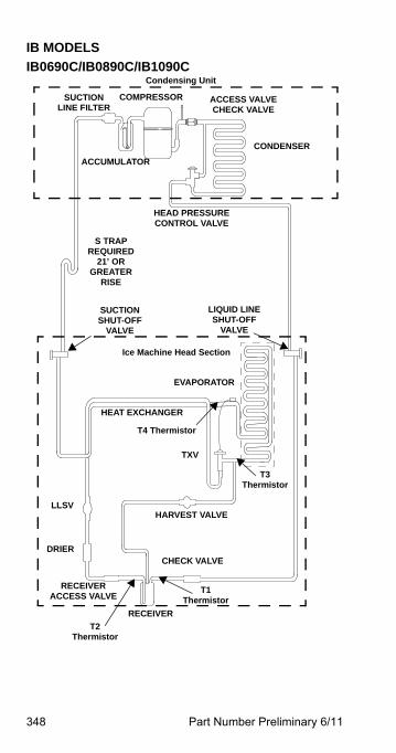
348 Part Number Preliminary 6/11
IB MODELS
IB0690C/IB0890C/IB1090C
RECEIVER
RECEIVER ACCESS VALVE
LLSV
SUCTIONSHUT-OFF
VALVE
HEAT EXCHANGER
CHECK VALVE
HEAD PRESSURECONTROL VALVE
ACCUMULATOR
TXV
HARVEST VALVE
COMPRESSOR
EVAPORATOR
LIQUID LINESHUT-OFF
VALVE
CONDENSER
S TRAP REQUIRED
21’ OR GREATER
RISE
DRIER
SUCTIONLINE FILTER
Ice Machine Head Section
Condensing Unit
ACCESS VALVECHECK VALVE
T1 Thermistor
T2 Thermistor
T4 Thermistor
T3 Thermistor


Manitowoc Ice2110 South 26th Street, P.O. Box 1720
Manitowoc, WI 54221-1720, USAPh: 920-682-0161 Fax: 920-683-7589
Visit us online at: www.manitowocice.com
© 2011 ManitowocPart Number Preliminary 6/11