Embed Size (px)
Citation preview

Indoor Navigation for Mobile Robots:
Control and Representations
Philipp Althaus
Stockholm 2003
Doctoral DissertationRoyal Institute of Technology
Numerical Analysis and Computer ScienceComputational Vision and Active Perception Laboratory

Akademisk avhandling som med tillstand av Kungl Tekniska Hogskolan framlag-ges till offentlig granskning for avlaggande av teknisk doktorsexamen fredagen den21 november 2003 kl 13.00 i Kollegiesalen, Administrationsbyggnaden, Kungl Tek-niska Hogskolan, Valhallavagen 79, Stockholm.
ISBN 91-7283-605-9TRITA-NA-0322ISSN 0348-2952ISRN KTH/NA/R-03/22CVAP 281
c© Philipp Althaus, October 2003
Universitetsservice US-AB, Stockholm 2003

Abstract
This thesis deals with various aspects of indoor navigation for mobile robots. For asystem that moves around in a household or office environment, two major problemsmust be tackled. First, an appropriate control scheme has to be designed in orderto navigate the platform. Second, the form of representations of the environmentmust be chosen.
Behaviour based approaches have become the dominant methodologies for de-signing control schemes for robot navigation. One of them is the dynamical systemsapproach, which is based on the mathematical theory of nonlinear dynamics. Itprovides a sound theoretical framework for both behaviour design and behaviourcoordination. In the work presented in this thesis, the approach has been usedfor the first time to construct a navigation system for realistic tasks in large-scalereal-world environments. In particular, the coordination scheme was exploited inorder to combine continuous sensory signals and discrete events for decision makingprocesses. In addition, this coordination framework assures a continuous controlsignal at all times and permits the robot to deal with unexpected events.
In order to act in the real world, the control system makes use of representationsof the environment. On the one hand, local geometrical representations parame-terise the behaviours. On the other hand, context information and a predefinedworld model enable the coordination scheme to switch between subtasks. Theserepresentations constitute symbols, on the basis of which the system makes deci-sions. These symbols must be anchored in the real world, requiring the capabilityof relating to sensory data. A general framework for these anchoring processes inhybrid deliberative architectures is proposed. A distinction of anchoring on twodifferent levels of abstraction reduces the complexity of the problem significantly.
A topological map was chosen as a world model. Through the advanced be-haviour coordination system and a proper choice of representations, the complexityof this map can be kept at a minimum. This allows the development of simplealgorithms for automatic map acquisition. When the robot is guided through theenvironment, it creates such a map of the area online. The resulting map is preciseenough for subsequent use in navigation.
In addition, initial studies on navigation in human-robot interaction tasks arepresented. These kinds of tasks pose different constraints on a robotic systemthan, for example, delivery missions. It is shown that the methods developed inthis thesis can easily be applied to interactive navigation. Results show a personalrobot maintaining formations with a group of persons during social interaction.
Keywords: mobile robots, robot navigation, indoor navigation, behaviour basedrobotics, hybrid deliberative systems, dynamical systems approach, topologicalmaps, symbol anchoring, autonomous mapping, human-robot interaction
ISBN 91-7283-605-9 • TRITA-NA-0322 • ISSN 0348-2952 • ISRN KTH/NA/R-03/22 • CVAP 281
iii

iv

Acknowledgments
Many people are responsible for the quality of this thesis. Over the last four years,they contributed either directly to my scientific work or to my quality of life ingeneral. There are too many persons involved to name them all. Here, I would liketo express my sincere thanks to the most important ones:
Henrik for directing my research throughout my studies. Thank you for yourcompetent scientific guidance as my supervisor, and for providing the great researchenvironment as the director of the Centre for Autonomous Systems.Guido, Frank, and Lars for all the enjoyable lunch breaks filled with discussionsabout soccer and other important aspects of life.Patric for all your valuable help with virtually any kind of hardware or softwareproblem. Just knowing that you are around improved the advancement of my work.All members of CAS and CVAP for contributing to the pleasant atmosphere everysingle day at work.Hiroshi Ishiguro for guiding my research during the four months in Japan.All members of IRC at ATR in Japan for providing a great research environment.Goran, Patrick, Juan, Peter, and Orjan for being my friends and making mefeel home in Stockholm almost immediately.The whole tidsfordrif gang for all the merry Tuesday evenings.Den Vollidioten, den Badenerstrassgspanli, den alten Handballkollegen, undmeinen Geschwistern Annette und Christian fur die vielen emails aus der Heimat,den tollen Besuchen in Stockholm und all den vergnuglichen Stunden wahrendmeiner Schweizaufenthalte.Meinem lieben Mami fur all die Unterstutzung wahrend meiner Doktorarbeit; inmoralischer und finanzieller Hinsicht.Min alskling Jeanette for allt stod och all karlek. Du ar bast!
This research has been sponsored by the Swedish Foundation for Strategic Researchthrough the Centre for Autonomous Systems. The support is gratefully acknowl-edged.
v

vi

Contents
1 Introduction 11.1 Control . . . . . . . . . . . . . . . . . . . . . . . . . . . . . . . . . 21.2 Representations . . . . . . . . . . . . . . . . . . . . . . . . . . . . . 31.3 Contributions . . . . . . . . . . . . . . . . . . . . . . . . . . . . . . 4
1.3.1 Indoor Navigation . . . . . . . . . . . . . . . . . . . . . . . 41.3.2 Automatic Map Acquisition . . . . . . . . . . . . . . . . . . 51.3.3 Human-Robot Interaction . . . . . . . . . . . . . . . . . . . 6
1.4 Outline . . . . . . . . . . . . . . . . . . . . . . . . . . . . . . . . . 6
2 Control System 92.1 Behaviour Based Robotics . . . . . . . . . . . . . . . . . . . . . . . 9
2.1.1 Overview . . . . . . . . . . . . . . . . . . . . . . . . . . . . 92.1.2 Behaviour Coordination . . . . . . . . . . . . . . . . . . . . 11
2.2 Dynamical Systems Approach . . . . . . . . . . . . . . . . . . . . . 132.2.1 Behavioral Variables . . . . . . . . . . . . . . . . . . . . . . 142.2.2 Behavioural Dynamics . . . . . . . . . . . . . . . . . . . . . 152.2.3 Competitive Dynamics . . . . . . . . . . . . . . . . . . . . . 16
2.3 System Design . . . . . . . . . . . . . . . . . . . . . . . . . . . . . 172.3.1 Dynamics of Heading Direction . . . . . . . . . . . . . . . . 192.3.2 Dynamics of Speed . . . . . . . . . . . . . . . . . . . . . . . 242.3.3 Behaviour Coordination . . . . . . . . . . . . . . . . . . . . 29
2.4 Discussion . . . . . . . . . . . . . . . . . . . . . . . . . . . . . . . . 33
3 Representations 353.1 Geometrical Representations . . . . . . . . . . . . . . . . . . . . . 36
3.1.1 Local Representations . . . . . . . . . . . . . . . . . . . . . 363.1.2 Maps . . . . . . . . . . . . . . . . . . . . . . . . . . . . . . 37
3.2 Symbol Anchoring . . . . . . . . . . . . . . . . . . . . . . . . . . . 403.2.1 Introduction . . . . . . . . . . . . . . . . . . . . . . . . . . 403.2.2 The Proposed Framework . . . . . . . . . . . . . . . . . . . 42
3.3 Implementation . . . . . . . . . . . . . . . . . . . . . . . . . . . . . 443.3.1 The Reactive Level . . . . . . . . . . . . . . . . . . . . . . . 46
vii

viii Contents
3.3.2 The Deliberative Level . . . . . . . . . . . . . . . . . . . . . 483.4 Discussion . . . . . . . . . . . . . . . . . . . . . . . . . . . . . . . . 50
4 Evaluation 534.1 Robot and Environment . . . . . . . . . . . . . . . . . . . . . . . . 534.2 Office Navigation . . . . . . . . . . . . . . . . . . . . . . . . . . . . 54
4.2.1 Driving along a Corridor . . . . . . . . . . . . . . . . . . . . 554.2.2 A Trial over a Long Distance . . . . . . . . . . . . . . . . . 58
4.3 Anchoring Issues . . . . . . . . . . . . . . . . . . . . . . . . . . . . 634.3.1 The Reactive Level . . . . . . . . . . . . . . . . . . . . . . . 634.3.2 The Deliberative Level . . . . . . . . . . . . . . . . . . . . . 63
4.4 Discussion . . . . . . . . . . . . . . . . . . . . . . . . . . . . . . . . 64
5 Automatic Map Acquisition 675.1 Introduction . . . . . . . . . . . . . . . . . . . . . . . . . . . . . . . 675.2 Implementation . . . . . . . . . . . . . . . . . . . . . . . . . . . . . 68
5.2.1 Person Following . . . . . . . . . . . . . . . . . . . . . . . . 685.2.2 Acquisition of the Map . . . . . . . . . . . . . . . . . . . . 71
5.3 Results . . . . . . . . . . . . . . . . . . . . . . . . . . . . . . . . . . 745.4 Discussion . . . . . . . . . . . . . . . . . . . . . . . . . . . . . . . . 77
6 Human-Robot Interaction 796.1 Introduction . . . . . . . . . . . . . . . . . . . . . . . . . . . . . . . 796.2 The Experimental Setup . . . . . . . . . . . . . . . . . . . . . . . . 81
6.2.1 The Platform . . . . . . . . . . . . . . . . . . . . . . . . . . 816.2.2 The Scenario . . . . . . . . . . . . . . . . . . . . . . . . . . 816.2.3 Psychological Considerations . . . . . . . . . . . . . . . . . 83
6.3 Implementation . . . . . . . . . . . . . . . . . . . . . . . . . . . . . 836.3.1 Control . . . . . . . . . . . . . . . . . . . . . . . . . . . . . 836.3.2 Representations . . . . . . . . . . . . . . . . . . . . . . . . . 87
6.4 Results . . . . . . . . . . . . . . . . . . . . . . . . . . . . . . . . . . 906.5 Discussion . . . . . . . . . . . . . . . . . . . . . . . . . . . . . . . . 93
7 Discussion 957.1 Indoor Navigation . . . . . . . . . . . . . . . . . . . . . . . . . . . 957.2 Extensions . . . . . . . . . . . . . . . . . . . . . . . . . . . . . . . . 987.3 Open Issues . . . . . . . . . . . . . . . . . . . . . . . . . . . . . . . 98
Bibliography 101

List of Figures
2.1 The hybrid deliberative architecture . . . . . . . . . . . . . . . . . 102.2 The dynamics of heading direction φ for go to . . . . . . . . . . . 192.3 The dynamics of heading direction φ for obstacle avoidance . . 202.4 The dynamics of heading direction φ in the case of two obstacles . 212.5 The dynamics of heading direction φ in the case of two obstacles . 212.6 Illustration of the choice of σ . . . . . . . . . . . . . . . . . . . . . 222.7 The fixpoints of the φ-dynamics dependent on Dobst . . . . . . . . 232.8 The dynamics of heading direction φ for wall avoidance . . . . 242.9 Change of ψgoal while the robot is moving . . . . . . . . . . . . . . 252.10 The dynamics of speed v for go to . . . . . . . . . . . . . . . . . . 262.11 The dynamics of speed v for obstacle avoidance . . . . . . . . . 272.12 The dynamics of speed v in the case of two obstacles . . . . . . . . 282.13 Fusion of go to and obstacle avoidance . . . . . . . . . . . . . 312.14 An arbitration scheme is needed to prioritise obstacle avoidance 322.15 The fixpoints of the wgoto-dynamics dependent on ρ . . . . . . . . 33
3.1 The topological map of our institute . . . . . . . . . . . . . . . . . 393.2 Placement of nodes . . . . . . . . . . . . . . . . . . . . . . . . . . . 393.3 Information flow in a general control system. . . . . . . . . . . . . 413.4 The organisation for anchoring on different levels of abstraction . . 423.5 The organisation of the navigation system . . . . . . . . . . . . . . 45
4.1 The Scout robot used in the experiments. . . . . . . . . . . . . . . 544.2 The topological map of the environment at ATR . . . . . . . . . . 554.3 The trajectory of the robot in a corridor . . . . . . . . . . . . . . . 564.4 Time plot of the absolute values of the weights . . . . . . . . . . . 564.5 The trajectory of the robot in our institute . . . . . . . . . . . . . 584.6 The track through the topological map . . . . . . . . . . . . . . . . 594.7 The trajectory at the beginning of the mission . . . . . . . . . . . 604.8 Time plot of the absolute values of the weights . . . . . . . . . . . 604.9 The trajectory at the end of the mission . . . . . . . . . . . . . . . 614.10 Time plot of the absolute values of the weights . . . . . . . . . . . 624.11 The robot at two different locations in the same corridor . . . . . . 63
ix

x List of Figures
4.12 The robot at two different locations among the same obstacles . . 64
5.1 The robot is following a person around the institute. . . . . . . . . 695.2 The topological map of our institute . . . . . . . . . . . . . . . . . 725.3 Correct placement of nodes during the map acquisition process . . 735.4 A map of our institute acquired by the robot . . . . . . . . . . . . 745.5 A map of our institute acquired by the robot . . . . . . . . . . . . 755.6 A cluttered corridor in our institute . . . . . . . . . . . . . . . . . 76
6.1 The robotic system Robovie. . . . . . . . . . . . . . . . . . . . . . 826.2 The dynamics of heading direction φ for keep distance . . . . . . 856.3 The dynamics of speed v for keep distance . . . . . . . . . . . . 866.4 The state diagram for the interaction scenario . . . . . . . . . . . . 896.5 The robot approaches the group of people. . . . . . . . . . . . . . . 916.6 The person on the right hand side is leaving the formation. . . . . 926.7 The third person is returning and approaching the group. . . . . . 926.8 The robot leaves the group of people. . . . . . . . . . . . . . . . . . 93

Chapter 1
Introduction
Today, various robotic systems are used in industry. They are applied to taskslike packing, welding, and painting. These static manipulators operate in prede-fined safe workspaces with emphasis on speed and precision. Very different typesof systems are autonomous robots built on mobile platforms, where a new degree ofcontrol flexibility is needed. As opposed to industrial robots, they move around intheir environment, which is often highly unstructured and unpredictable. Slowly,various markets are emerging for this type of robotic systems. Entertainment appli-cations and different types of household or office assistances are the primary targetsin this area of development. The Aibo dog from Sony and the Trilobite vacuumcleaner from Electrolux are early examples of this future industry.
All these existing and potential applications of autonomous systems have oneproblem in common: navigation. The robots must move about in their surround-ings in a flexible and robust manner. Since environments in real-world applicationsare highly unpredictable, the system gathers sensory information from which itmust extract representations of its surroundings. These representations are usedby the control system in order to fulfill the navigational tasks. The main focusof this thesis is precisely these two topics, control of the platform and anchoringsensory information to objects in the real world. It must be emphasised that thesetwo problems are in no way independent of each other. The design of a controller isheavily dependent on the nature of the available knowledge of the robot’s immedi-ate surroundings as well as the large-scale structure of the environment. The richerand more accurate this knowledge is, the easier it becomes to find a suitable controlalgorithm. However, acquiring this knowledge, which means extracting representa-tions from sensory data, is a delicate problem in itself. Usually, the more complexthese representations are, the more computational power is needed. Hence, thecomplexity of the anchoring processes must be kept within certain bounds to allowthe control system to guide the robot at a reasonable speed.
The problems of controlling the platform and acquiring knowledge of its sur-roundings can be highly simplified by engineering the environment. For example,
1

2 Chapter 1. Introduction
the whole setting can be designed to account for the specifics of the robotic plat-form as in factory spaces. Alternatively, easy identifiable artificial landmarks canbe placed to simplify self-localisation of the platform. Buried wires to guide au-tonomous lawn mowers are a typical example. However, for large markets targetingall households and office spaces additional investments for engineering environmentsare believed to be too high. Hence, this thesis focuses on minimalistic models interms of environment modelling. The navigation system developed here is applica-ble to any indoor environment consisting of rooms, corridors, and doorways, whichare accessible by a wheeled platform.
The remainder of this chapter is organised as follows. First, the two main topics,control (section 1.1) and representations (section 1.2), are introduced. In section1.3, the scientific contributions are addressed. Finally, an outline of this thesis isgiven in section 1.4.
1.1 Control
The first so-called intelligent systems were dominated by approaches from classicalartificial intelligence. Complete knowledge of the environment and a deterministicoutcome of actions was presumed. Then, a symbol based planner calculated anaction sequence to be executed in order to accomplish the given goal. The appli-cability of this methodology to mobile robots was rather limited due to variousdeficiencies. Complete knowledge of the world is usually not available and theoutcome of control actions is subject to noise introduced by imperfect actuatorsand other outside influences from the surrounding. Hence, the robot must makeuse of sensors to update its belief of the world. The first systems for autonomousrobots were designed based on these sensory data and a reasoning system inspiredfrom classical AI (see (Moravec, 1983) for a review). They carried out extensiveplanning and replanning due to the noise in sensory data and outcome of motoractions. Thus, enormous computation time was used, which made the robots veryslow. Furthermore, environments are often dynamic in an unpredictable way, whichmeans that even in theory it is impossible to capture all of their properties.
To overcome the flaws of classical AI approaches, a new paradigm, behaviourbased robotics, has established itself over the last decade. Arkin (1998) providesan excellent overview of existing systems. In a behaviour based approach the con-trol of the platform is distributed to several so called behaviours. Each of thesebehaviours is tightly coupled to sensory data and controls the robot in a reactiveway to accomplish some subproblem of the navigational task. Typical examplesof such subtasks are “obstacle avoidance”, “wall following”, or “approach goal”.Intelligence arises through the combination of these perception-action loops ratherthan through symbolic reasoning. Despite their success, these initial purely reac-tive approaches were rather limited in solving complex tasks, for example to reach adistant goal in a large-scale environment. Hence, elements of the classical approachwere incorporated again to enable planning and reasoning on a symbolic level using

1.2. Representations 3
some predefined model of the world. This led to hybrid deliberative systems1 func-tioning on two levels of control. On the one hand, a reactive part deals with localnavigation based on immediate sensor readings. On the other hand, a deliberativepart takes care of long term mission planning to achieve certain higher level goals.
There are many different methodologies to design these hybrid deliberative ar-chitectures, each with its own advantages and drawbacks. Unfortunately, most ofthem lack a sound theoretical framework to express task constraints in a mathemat-ical way. However, the dynamical systems approach by Schoner and Dose (1992)models behaviours and their coordination based on nonlinear dynamical systems.A unified framework incorporates both levels of control of a hybrid deliberative ar-chitecture. Through mathematical design, task constraints can easily be expressedin the system. Furthermore, it makes it possible to combine the continuous natureof geometrical properties and control signals with the discrete nature of decisionmaking and task switching. One great advantage of this property is that a contin-uous control signal, which is applied to the robot’s actuators, can be assured at alltimes.
The dynamical systems approach was the control framework of choice in thestudies covered by this thesis. Earlier, it was deployed successfully in simulationprojects and on robots in simplified real-world settings. Here, it was applied toa robot, whose primary task was to navigate from any starting position to anarbitrary goal point in a large-scale indoor environment.
1.2 Representations
A control system acting in the real world needs some kind of knowledge about itsenvironment. In robotics, this knowledge is usually referred to as representations,which provide parameters to the controller. These representations are mostly geo-metrical, capturing the properties of the environment. Furthermore, they can alsobe in the form of labelled entities, which are typically used for task specification.In AI, this knowledge is often referred to as symbols allowing decision making andreasoning about the world. In behaviour based systems two different types of rep-resentations or symbols are considered. On the one hand, symbols with geometricalproperties reflect the immediate surrounding of the robot in order to allow safe nav-igation fulfilling local tasks. In indoor navigation these types of symbols includewalls, doorways, or obstacles such as tables, chairs, and people. On the other hand,a model of the large-scale structure of the area is required to enable planning ofroutes to fulfill an entire mission. These representations are usually in the form ofmaps, which have geometrical and topological properties.
Geometric properties of objects are extracted from sensory information to allowsafe navigation. Naturally, the type and quality of these properties are heavily
1In the literature, they are often also referred to as “hybrid systems”. Throughout this thesisthe term “hybrid deliberative system” is used to make a distinction to the definition of hybridsystems in control theory.

4 Chapter 1. Introduction
dependent on the sensors used by the system. The most common ones are rangesensors, such as sonars or lasers. Another, more advanced approach is the use ofcameras and computer vision techniques to extract information from pictures, butthese tend to be computationally expensive. The studies covered in this thesis focuson the use of ultrasonic sensors. However, there is nothing in the methodology thatprevents employing more advanced sensing capabilities. Furthermore, odometricinformation from wheel encoders can be used to combine several measurementstaken at different time instances.
Maps are used to reflect the large-scale structure of environments. In general,they are predefined and constitute the system’s a priori knowledge about the world.Many different types of maps are used in the literature. This choice is also depen-dent on the sensing capabilities of the robot, since the system needs modules forplace recognition. Only this capability allows self-localisation and subsequent useof the map to achieve the navigational task. The quality of the odometric informa-tion available often poses the major constraints on the complexity of the map. Atopological map containing low complexity information was applied in the studiesof this thesis, since the focus lies on minimalistic models that are computationallyinexpensive and can be applied to basically every indoor environment. Apart fromusing a map for navigation, the problem of acquiring this map autonomously is amajor issue in research. Naturally, the methodologies and algorithms to acquiresuch a map are very much dependent its actual type and complexity.
Both types of representations, geometrical properties of nearby objects andmaps of large-scale structures, must be related to sensory data. Establishing thisconnection and maintaining it over time is called symbol anchoring. This problem isusually solved on a system by system basis due to a lack of a general methodology.However, such a general framework would be very useful as a design principle andto enable comparison of different solutions. In this thesis an attempt of a frameworkfor symbol anchoring in hybrid deliberative systems is presented.
1.3 Contributions
This section summarises the scientific contributions of this thesis. Furthermore,publications which cover most of the material are listed. These papers can bedownloaded at http://www.nada.kth.se/~philipp/Publications.
The main contribution concerns navigation in indoor environments (section1.3.1). In addition, a map acquisition scheme was developed (section 1.3.2), andstudies on navigation in human-robot interaction were performed (section 1.3.3).
1.3.1 Indoor Navigation
This thesis covers many different aspects of indoor navigation for autonomousrobots: behaviour design, behaviour coordination, map representations, and symbolanchoring.

1.3. Contributions 5
The dynamical systems approach is applied to realistic tasks in the real world forthe first time. In contrast to previous implementations, the speed of the platformis incorporated in the framework. Then, the behaviour coordination scheme isexploited thoroughly. Continuous sensory signals and discrete information from thetopological map are integrated into the same framework. Furthermore, these dataare used for decision making, which is of a discrete nature. However, the integrationof dynamical systems leads to smooth switching between different navigational taskswhich ensures a continuous control signal at all times.
The system uses symbols on both levels of control. On the reactive level, ge-ometrical representations of the environment determine the output of individualbehaviours. On the deliberative level, context information enables coordination ofthese behaviours. A framework is proposed, where the anchoring of these symbolsin the real world clearly distinguishes between the two levels of abstraction.
In essence, a unified navigation scheme for large-scale indoor environments ispresented. It copes with unforeseen situations in a flexible manner and, throughits low complexity processes, uses very limited CPU time.
• Althaus P., Christensen H. I., and Hoffmann F. Using the dynamical systemapproach to navigate in realistic real-world environments. In Proceedings ofthe IEEE/RSJ International Conference on Intelligent Robots and Systems,pages 1023-1029, 2001.
• Althaus P. and Christensen H. I. Smooth task switching through behaviourcompetition. In Intelligent Autonomous Systems 7, pages 9-17. IOS Press,Amsterdam, NL, 2002.
• Althaus P. and Christensen H. I. Behaviour coordination for navigation in of-fice environments. In Proceedings of the IEEE/RSJ International Conferenceon Intelligent Robots and Systems, pages 2298-2304, 2002.
• Althaus P. and Christensen H. I. Smooth task switching through behaviourcompetition. Robotics and Autonomous Systems, 44(3-4):241–249, 2003.
• Althaus P. and Christensen H. I. Behavior coordination in structured envi-ronments. Advanced Robotics, 17(7):657–674, 2003.
• Althaus P. and Christensen H. I. A framework for anchoring in hybrid delib-erative systems. Submitted to Autonomous Robots, 2003.
1.3.2 Automatic Map Acquisition
The navigation system was enhanced with a behaviour for person following. Thisenables the robot to follow a guide through a previously unknown environment. Viaa basic interface, it receives input about the existence of corridors and the names ofrooms. The system is able to build its own topological map of the area with simplealgorithms and very low computational complexity. This map can in turn be usedby the robot to navigate autonomously throughout the whole environment.

6 Chapter 1. Introduction
• Althaus P. and Christensen H. I. Automatic map acquisition for navigation indomestic environments. In Proceedings of the IEEE International Conferenceon Robotics and Automation, pages 1551–1556, 2003.
1.3.3 Human-Robot Interaction
During a 4 months stay at the Intelligent Robotics and Communication Labora-tories at the Advanced Telecommunications Research Institute (ATR) in Kyoto(Japan), navigation in the context of human-robot interaction was studied. Theframework used for office navigation was extended by adding new behaviours. Thetopological map was connected to a state diagram reflecting the events in an in-teraction task. On its way through the offices the robot was able to join a groupof people engaged in a conversation, and subsequently resuming its old plan. Thisproject was a first attempt to study navigation specifically for human-robot inter-action.
• Althaus P., Ishiguro H., Kanda T., Miyashita T. and Christensen H. I. Nav-igation for human-robot interaction tasks. Submitted to IEEE InternationalConference on Robotics and Automation, 2004.
1.4 Outline
The main topic of this thesis, indoor navigation, is covered in the next three chap-ters. The control system is studied in chapter 2, the issues on representations andsymbol anchoring in chapter 3, and the results in chapter 4. Chapter 5 covers themap acquisition procedure with its results, while chapter 6 presents the studieson navigation in human-robot interaction tasks. Finally, conclusions are drawn inchapter 7.
Chapter 2: Control System
An overview of different behaviour based approaches is given with emphasis onbehaviour coordination. The dynamical systems approach is introduced in detail.Then, the motivation and the design of the navigation behaviours and their coor-dination is presented.
Chapter 3: Representations
Issues on local geometrical representations and indoor maps are presented. Symbolanchoring in the real world are discussed and the general framework for anchoringin hybrid deliberative architectures is introduced. Then, the choices of symbols inthese studies are motivated and all the anchoring processes are discussed in detail.

1.4. Outline 7
Chapter 4: Evaluation
First, the actual indoor environment and the robot used in the experiments andits sensing capabilities are introduced. Navigation results in the office environmentof our institute are presented. Emphasis is placed on decision making on bothlevels of control: the reactive (attractor dynamics) and the deliberative (behaviourcoordination). In addition, some issues related to symbol anchoring are discussed.
Chapter 5: Autonomous Map Acquisition
Initially, an overview of map learning in indoor environments is given. Then, thescenario of semi-autonomous map acquisition is introduced. The acquisition mech-anisms and results are presented. The chapter concludes with a discussion.
Chapter 6: Human-Robot Interaction
The special constraints on navigation in human-robot interaction tasks are dis-cussed. Then, the behaviour design and coordination for a test scenario are pre-sented. Furthermore, the extension of the topological map, the state diagram, isintroduced. Finally, some initial results are displayed, followed by a discussion.
Chapter 7: Discussion
Finally, the thesis is summarised with particular focus on the office navigationsystem as a whole. Moreover, the major open issues and avenues of future researchare discussed.

8

Chapter 2
Control System
This chapter covers all issues related to the control of the indoor navigation system.Behaviour based control is the dominant paradigm in mobile robotics. Its basicprinciples and some examples are discussed in section 2.1. The dynamical systemsapproach became the control framework of choice in the work of this thesis and isintroduced in section 2.2. In section 2.3 the actual design of the indoor navigationsystem is presented. Finally, the chapter concludes with a summary and a discussion(section 2.4).
2.1 Behaviour Based Robotics
First, a bit of history and an overview on the behaviour based approach is given(section 2.1.1). Only the basic concepts and the terminology are introduced here.For a broad review on behaviour based systems see (Arkin, 1998). Yet one focus ofthis thesis is on the question of how to combine different behaviours. This problemand existing solutions are discussed in more detail in section 2.1.2.
2.1.1 Overview
As outlined in the introduction (section 1.1), the classical AI approaches to robotics(Moravec, 1983) were limited by their computational complexity. The actions of therobot were determined through reasoning in a central world model. Hence, thesesystems scaled poorly to real-world complexity and could hardly react to unforeseenevents in real-time. Two new, at that time revolutionary, ideas paved the way forbehaviour based robotics: situatedness and modularity.
Situatedness describes the idea that intelligence has to be studied in terms ofan agent interacting with its environment (Brooks, 1990). Which means that thesensors which are deployed to perceive the environment and the motors used tomove about play a central role. It was understood that a tight coupling between
9

10 Chapter 2. Control System
sensors and motors can lead to surprisingly advanced behaviour without using anyform of abstract reasoning. Braitenberg (1984) gives a brilliant insight into thisnew paradigm.
By studying humans performing various tasks, Arbib et al. (1987) discoveredthat complex movements can be described by different, rather independent modules.They called these modules motor schemas. Each of these schemas takes care of onesubtask of the whole action. By combining these simpler units of motor control,rather complex moving patterns could be explained.
In robotics, these two insights led to the concept of behaviours. A behaviouris a module that couples motor commands very tightly to sensory readings. Be-haviours have a minimal internal state and solve tasks of limited complexity in areactive manner. Nevertheless, intelligence arises through the combination of sev-eral behaviours and the interaction of the robot with the world. The subsumptionarchitecture of Brooks (1986) was a first example of these new ideas implemented ona real robot wandering around in an office environment. A nice review on this shiftin paradigm is given in (Brooks, 1991b). The initial success of such architecturesled to a design philosophy which could be called strict behaviourism, where anykind of representations and reasoning in the sense of traditional AI were rejected(Brooks, 1991a). However, this purely reactive approach failed to design systemsfor more complex missions and it was argued that it does not scale to human-liketasks (Tsotsos, 1995). Consequently, the behaviour based systems were enhancedby a reasoning module which takes care of mission planning. Usually, this moduleis steering the coordination of the different behaviours. As a result, a hybrid de-liberative architecture as depicted in Figure 2.1 became the most common type ofbehaviour based systems.
Mot
ors
Sen
sors
Planning/Reasoning
Coordination
Behaviour N
Behaviour 1
Behaviour 2
Figure 2.1. The hybrid deliberative architecture. An arbitrary amount of be-haviours solve subtasks in a reactive manner. A coordination scheme is used todetermine the appropriate motor command. This scheme is influenced by a reason-ing system creating plans for complex missions.
The design of the individual behaviours is strongly dependent on the platformused. Its shape, actuators, and sensors influence the nature of these reactive mod-ules. Nevertheless, some types of behaviours have become the standard choice for

2.1. Behaviour Based Robotics 11
navigational tasks. Every system moving around in the world needs two basic abil-ities: approaching some kind of target and avoiding obstacles on its way. Moreover,additional behaviours like, for example, “corridor following”, “door passing”, “wallfollowing”, and “avoid past” are very common. The exact choice of behaviours ishighly dependent on the environment and the tasks to be achieved. Furthermore,the behaviour based approach is not restricted to navigation. It is also successfullyused for learning and group behaviour (Mataric, 1997), and on humanoid robots(Brooks, 1997).
There were many different strategies developed to combine the individual be-haviours. The same holds for the way the planning module is integrated into thearchitecture. We will investigate this issue in more detail in the following section.
2.1.2 Behaviour Coordination
The behaviour based approach to robotics is a conceptual framework; and as suchit does not specify a particular formalism for the design of the system. This greatfreedom makes it also hard to compare different implementations. As opposedto classical AI approaches, this paradigm is not based on provable facts such asplan correctness, optimality, and so forth. However, the planning module of ahybrid deliberative architecture (see Figure 2.1) can usually be built using thesetheoretical tools. The meeting point of these two design techniques is at the levelof behaviour coordination. Here, it must be decided at what time which set ofbehaviours should be active. Furthermore, behaviours have their own, possiblyincompatible, objectives. Hence, from several behaviour outputs, a coordinationscheme has to determine a single control signal which can be applied to the actuatorsof the robot. In general, existing coordination approaches can be divided into twoclasses: behaviour arbitration and behaviour fusion. Different systems of these twoclasses are introduced below. For a detailed comparison see (Pirjanian, 1998).
Behaviour Arbitration
Arbitration mechanisms select at all times the most appropriate behaviour. Thisbehaviour is, then, taking control of the robot and determining the action to betaken. Arbitration strategies can roughly be divided into priority based and statebased.
In priority based arbitration, behaviours are ordered in a hierarchical way. Thesubsumption architecture (Brooks, 1986) is an example using this type of arbitra-tion. Each behaviour has its own level of competence. A behaviour can suppressinput and inhibit output of modules on lower levels dependent on sensory dataor a timing policy. This mechanism of choosing the most appropriate behavioursis preprogrammed. Hence, this is a purely reactive approach without any centralrepresentations or reasoning system present. Nevertheless, Mataric (1992) couldextend this architecture to a goal-driven robot by integrating representations onthe level of individual behaviours.

12 Chapter 2. Control System
In state based arbitration, the robot’s state in a plan execution determines theappropriate behaviour. This plan execution is typically defined in the frameworkof discrete event systems (Ho, 1991). Kosecka and Bajcsy (1994), for example,designed such a system for robot navigation. Each state corresponds to one be-haviour. At detection of certain events, a state change occurs; thus, activation ofa new behaviour. A more abstract formulation of this approach can be found in(Kosecka et al., 1997). Another navigation example using the same concepts waspresented by Arkin and MacKenzie (1994). Their terminology is based on a for-mal definition of motor schemas (Arkin, 1990) and finite state acceptor diagrams.The latter framework is also very common for systems performing human-robotinteraction tasks (Kanda, Ishiguro, Imai, Ono and Mase, 2002).
Behaviour Fusion
Fusion mechanisms allow several behaviours, at the same time, to contribute to theaction taken by the robot. These behaviours have typically different, and possiblyincompatible, objectives. The strategies to determine a single motor command fromthese multiple objectives can roughly be classified into voting, fuzzy approaches, andsuperposition.
In voting based fusion (Payton et al., 1990), each behaviour casts votes for thevarious possible actions. Then, the action receiving the most votes is applied to theactuators of the platform. This approach was successfully used in the navigationsystem DAMN (Rosenblatt, 1997), and also for other tasks like steering a camerahead (Pirjanian et al., 1998).
Approaches using fuzzy logic (Saffiotti et al., 1995) are, in principle, similar tovoting based fusion. Instead of voting for different actions, each behaviour definesa membership function over the set of possible actions, dependent on the situationthe robot faces. These functions are combined using standard fuzzy reasoning. Theresulting membership function is defuzzyfied to compute a single motor action. Yenand Pfluger (1995) made the similarity to voting based fusion explicit by formulatinga fuzzy version of the DAMN architecture.
The most popular approach to superposition based fusion is the potential fieldmethod (see (Latombe, 1991) for an introduction). Initially, it was developed forpath planning in a manipulation task by Khatib (1986). Potential functions are de-fined around obstacles and a goal state. The solution of the path planning problemis to follow the gradient of the superposition of these potentials, which eventuallyleads to the target configuration. In (Rimon and Koditschek, 1992) a wide varietyof potential functions are introduced in the context of navigation. Arkin (1990)adapted this method to behaviour based robotics using the terminology of motorschemas (Arbib et al., 1987). Here, each behaviour defines a potential functionbased on the sensory context. The gradient of each function is determined at theposition of the robot, which gives the desired direction of movement. By a weightedaddition of the gradients from different behaviours, the motor action of the platformis determined. This method is widely used and particularly easy to implement using

2.2. Dynamical Systems Approach 13
range sensors (Veelaert and Bogaerts, 1999). Another approach to superpositionbased fusion is the dynamical systems approach (Schoner and Dose, 1992; Schoneret al., 1995). This is the framework of choice for the work presented in this thesisand will be introduced in detail in section 2.2.
Planning and Reasoning
The behaviour based approach was novel in the aspect of distributing sensory pro-cessing and control to individual modules. However, central representations ofphysical objects and plans are needed to achieve higher level missions (Lyons, 1993;Chatila, 1995). In a hybrid deliberative architecture, a planner or any kind of rea-soning system is using these representations to coordinate the activation of theindividual behaviours. Note that this planning problem is easier than the one ofclassical AI approaches. Now, the planner operates in the “behaviour space” asopposed to the “action space”. In other words, it has to choose between a, usually,rather small set of behaviours, instead of the set of all possible actions of the robot.A general formulation of the problem of combining reactive perception-action sys-tems with an abstract reasoning level is presented in (Bajscy and Large, 1999).
Most of the behaviour coordination schemes introduced above were implementedin combination with a reasoning module as depicted in Figure 2.1. The integrationof discrete event systems (Ho, 1991; Kosecka and Bajcsy, 1994) allows theoreticalanalysis of plan execution. A framework of combining a planner with robot schemasis presented in (Lyons and Hendriks, 1995). Also in approaches deploying behaviourfusion, the contributions of the individual behaviours can be governed by a planner.Rosenblatt (2000), for example, integrates this with a voting scheme by maximisinga utility function. In the work of this thesis, the dynamical systems approach hasbeen combined with a planner that finds a path through a topological map (section3.3.2).
The reasoning parts of hybrid deliberative architectures are of many differenttypes with various complexity. The planner in the navigation system presented ofthis thesis performs a simple search through a graph. Depending on the goals to beachieved, it can be more complex as the TCA system (Simmons, 1994) incorporatingperception and improvement of efficiency. In (Peterson and Cook, 2003) the conceptof uncertainty was integrated for a task of playing miniature golf. Often, generalreasoning systems for robot control are not explicitly hybrid. They are designedin a hierarchical manner (Albus, 1991), where the lowest level of this hierarchy isequivalent to the reactive part of a hybrid deliberative architecture.
2.2 Dynamical Systems Approach
The dynamical systems approach unifies both the design of behaviours and theircoordination in one framework. This approach is based on the theory of non-linear dynamical systems. Here, we consider mainly the qualitative properties of

14 Chapter 2. Control System
the mathematical framework. Relevant concepts like attractor, repellor, bifurca-tion, and stability are introduced later in this chapter. For a thorough theoreticalbackground on dynamical systems there are a number of excellent textbooks, forexample (Perko, 1991) and (Khalil, 1995). An introduction into the topic in thecontext of autonomous agents can be found in (Beer, 1995).
The approach was originally motivated from biology. It has been found thatthe behavioural information in the brain is organised in a way that underlies somedynamics (Schoner, 1991). Furthermore, also the nervous system follows dynamicallaws (Schoner and Kelso, 1988). This led to the idea of defining behaviours asdynamical systems in a space spanned by so-called behavioural variables (see section2.2.1). Others have used these mathematical tools as well. For example, Beer (1995)uses it for analysis of a six legged agent. Here, dynamical systems are, however,used as a design principle, rather than an analysis tool.
The dynamical systems approach was first introduced by Schoner and Dose(1992). The methodology for behaviour design was applied to different navigationtasks consisting of some form of target acquisition and obstacle avoidance. Ex-periments were mainly performed in simulation (Schoner and Dose, 1992; Schoneret al., 1995; Steinhage and Schoner, 1997; Large et al., 1999) and some simpli-fied real-world settings (Schoner et al., 1995; Neven and Schoner, 1996; Bicho andSchoner, 1997; Bicho et al., 2000; Bicho, 2000a). Moreover, the behaviour coor-dination scheme has been applied to simulation experiments only (Schoner andDose, 1992; Schoner et al., 1995; Large et al., 1999). In the work presented here,the methodology has been applied for the first time to the design of a system act-ing in realistic real-world environments. In particular, the behaviour coordinationscheme was exploited and explicitly connected to some planning module in orderto allow mission planning. This is done for fetch-and-carry type tasks in an indoorenvironment. Furthermore, the dynamical systems approach was also applicableto navigation for two robots cooperating (Large et al., 1999) or moving in forma-tion (Monteiro and Bicho, 2002). In addition, the same methodology was appliedto navigation in human-robot interaction as a part of this thesis, which will bepresented later in chapter 6.
The basic concepts of the dynamical systems approach are introduced below.These concepts will be further clarified in section 2.3 by means of the design ofthe navigation system. Other introductions into the topic and in-depth discussionsof the motivation of the methods used can be found in (Schoner and Dose, 1992;Schoner et al., 1995; Steinhage, 1998; Bicho, 2000b).
2.2.1 Behavioral Variables
Modelling takes place in the space of behavioural variables, here, described by thevector �x. These variables define the behavioural dimensions; a continua along whichbehaviour can change. At any time, the state of the system is defined by a specificpoint in this space. The first design choice in the dynamics systems approach is
2.2. Dynamical Systems Approach 15
to define the set of behavioural variables, such that the following conditions aresatisfied:
• Task constraints of a behaviour b must be expressible as a point or set ofpoints �xb in the space of these variables.
• The constraints �xb must be independent of the current state �x of the system.
• It must be possible to specify the points defining a task constraint by collectedsensory information or some internal world model.
• It must be possible to impose the time derivative �x of the behavioural variableson the actuator system of the robot.
In a navigation task, for example, the robot’s heading direction φ, measured againsta world-fixed reference direction, is usually one of those variables. The constraintfor a target approaching task can be defined by the point ψtarget, the directionof the target from the robot’s position. This value is independent of the robot’sactual heading direction. The direction of this target, of course, must be knownto the system. Furthermore, the time derivative φ is the turnrate, which on mostplatforms can be directly controlled.
2.2.2 Behavioural Dynamics
The next design step is to generate dynamical systems of the behavioural variables.For each behaviour b the time evolution of these variables is described by
�x = �fb(�x, P ) (2.1)
The function �fb can be interpreted as a force acting on the behavioural variablesdependent on the current state �x and a set of additional parameters P , whichdepend on the relative pose between the robot and its environment. This forceis designed in such a way that the point or the set of points �xb defining a taskconstraint are fixpoints of the dynamical system.
−→dx
dt
∣∣∣∣x=xb
= �fb(�xb, P ) = 0 (2.2)
If the task constraint �xb is a desired value of the behaviour than the fixpoint mustbe an attractor. In the example above, this is the case for ψtarget. On the otherhand, if the value of �x defining the task constraint is an undesired one (for examplethe direction of an obstacle), the fixpoint has to be a repellor. This concept willbecome clear in section 2.3, where the design of the actual behaviours is presented.

16 Chapter 2. Control System
Each attractor �xb can be characterised by its strength. This can be expressed bythe slope of the dynamics at the fixpoint for each dimension i of the space spannedby the behavioural variables.
λb,i = −∂fb,i(�x, P )∂xi
∣∣∣∣x=xb
(2.3)
After a perturbation in dimension i, the dynamics of behaviour b needs a certaintime to approach the attractor state again. This relaxation time can be charac-terised by λ−1
b,i ; the inverse of the strength of the attractor. While the robot ismoving through its environment, the parameters of the set P are gradually chang-ing their values. This can bring along a shift of the attractors in the space of thebehavioural variables. To ensure stability, which means that the system is in orclose to an attractor state at all times, this shift must occur on a slower timescalethan the attractor’s relaxation time. This condition can be assured by choosing therobot’s velocity and the strength of the attractors appropriately (see the design insection 2.3.2).
Furthermore, changes in a parameter of the set P can not only shift an attractorgradually, but also cause a bifurcation in the dynamical system. This means thatan attractor can become a repellor or vice versa. In general, the set of fixpoints isaltered, which brings along a complete change in strategy of the behaving system.This type of decision making will be illustrated, for example, with the design of anobstacle avoidance behaviour in section 2.3.1 (Figure 2.7).
To obtain the overall dynamics of the behavioural variables, multiple behavioursof a set B are aggregated by weighted addition of the individual contributions �fb.
�x =∑b∈B
|wb|�fb(�x, P ) + noise (2.4)
The weights wb ∈ [−1, 1] define the level of contribution of each behaviour andare computed based on the perceived context of operation (see section 2.2.3). Thenoise has a small amplitude and merely ensures that the dynamical system escapesunstable fix-points (repellors). Note that summing is only a method of combiningbehaviours. This linear combination is not a constraint on the overall behaviour,since all the contributions are, in general, nonlinear.
By combining different behaviours, the range of each individual dynamical sys-tem in the space of the behavioural variables becomes important. This propertydetermines, if two contributions interact with each other or if they are completelyindependent. Also this issue will be illustrated in section 2.3.1 by designing theactual behaviour for avoiding obstacles.
2.2.3 Competitive Dynamics
Coordination among behaviours is modelled by means of an additional competitivedynamics that controls the weights wb for each behaviour b, which evolve in the

2.3. System Design 17
following fashion:
τbwb = αb(wb − w3b ) −
∑b′ �=b
γb′,bw2b′wb + noise (2.5)
The first term constitutes a pitchfork bifurcation, which means that the dynamicspossesses stable fix-points at
wb =
{±1 if αb > 00 if αb < 0
(2.6)
The factors αb ∈ [−1, 1] are called competitive advantages. They determine thedegree to which a behaviour is appropriate and desirable in the present context. Inother words, a behaviour b is switched on for a positive competitive advantage andswitched off if αb is negative.
The need of activating a behaviour can often not only be determined by theenvironmental context. A certain behaviour can also conflict with another one be-ing currently active. The second term in equation 2.5 captures the competitivedynamics in that an active behaviour b′ of higher priority suppresses the activa-tion of another conflicting behaviour b. Hence, the factors γb′,b ∈ [0, 1] are calledcompetitive interactions. For |wb′ | ∼ 1 and γb′,b > αb, the point wb = 0 becomesthe new stable fix-point of behaviour b, despite a positive competitive advantageαb > 0.
While the robot is moving, the environmental context is changing, which in-fluences the parameters αb and γb′,b. This in turn modifies the amount and type(attractor/repellor) of fixpoints in the competitive dynamics, which can lead to achange in the navigation strategy. Hence, also on this level, decision making ismodelled by bifurcations in a nonlinear dynamical system. A detailed analysis ofhow the stability of fixpoints varies across different values of competitive advan-tages and interactions is given in (Large et al., 1999). Similar to the behaviouraldynamics, the noise term helps the system to escape unstable fixpoints (repellors).
Finally, instead of instantaneously switching behaviours on and off, they canbe activated and deactivated gradually in this framework. The rate at which thesetransitions take place is determined by the time constant τb.
2.3 System Design
As outlined in the introduction, the system developed here provides the navigationfunctionality of fetch-and-carry type tasks in large-scale indoor environments. Atypical mission of the robot starts at the charging station located in a room. Then,the platform has to drive to one or several goal points in the area, and eventually getback to recharge its batteries. It must be able to pass doors, drive along corridorsand approach the targets, while avoiding collisions on its way. The following fivebehaviours with their associated functionality were designed:

18 Chapter 2. Control System
• go to: moving towards a given goal point in an unstructured room in theabsence of obstacles. This goal can also be some intermediate point of a longermission (for example, the place in front of a door before leaving a room).
• obstacle avoidance: avoiding collision with any kind of obstruction, whileat the same time moving1.
• corridor following: guiding the robot along corridors in the absence ofobstacles.
• wall avoidance: driving towards the middle of long corridors throughavoiding its walls.
• door passing: passing a narrow gap to traverse between two rooms, from acorridor to a room, or vice versa.
Following the methodology of the dynamical systems approach outlined in section2.2, the behavioural variables �x have to be defined first. The robot’s heading φrelative to a world-fixed reference direction and the speed v of the platform werechosen.
�x =(φ
v
)(2.7)
Navigation behaviours can be expressed naturally in these terms, because con-straints are usually defined by directions of objects (target or obstacles) and byrestrictions on speed. Further, most mobile platforms accept control commandsspecifying the turnrate and the translational velocity. These values are providedby the behavioural dynamics. The turnrate φ directly, and the velocity can becalculated by integrating the acceleration v for each timestep.
In order to keep the mathematical analysis of the dynamical systems as simpleas possible, the dynamics of φ and v will not depend on each other for all behaviours(compare to equation 2.1).(
φ
v
)= �fb(φ, v, P ) =
(fb,φ(φ, P )fb,v(v, P )
)(2.8)
Since, we now deal with two one-dimensional systems, the analysis of fixpointsand their stability properties becomes much easier. Hence, for each of the basicbehaviours introduced above, two dynamical systems are designed. One for theheading direction (section 2.3.1) and one for the speed (section 2.3.2). It has beenattempted to define these systems in the simplest mathematical form possible,such that the desired functionality of each behaviour is achieved. The design of thecoordination among these basic behaviours is presented in section 2.3.3.
The explicit inclusion of the set of parameters P will be omitted in the remainderof this section. Moreover, all values denoting distances are expressed as a multiple ofthe robot’s radius. This keeps the formulas simpler and the constants dimensionless.
1Standing still would be a rather good strategy for avoiding collisions; however, not very usefulfor achieving a navigational task.

2.3. System Design 19
2.3.1 Dynamics of Heading Direction
All dynamical systems defined in this section are in some way dependent on theangle under which an object (target, obstacle, wall, corridor, or door) is seen fromthe robot’s actual position. These angles are measured from a world-fixed referencedirection. These parameters change gradually as the platform moves around inthe environment, which must be taken in consideration in order to assure thatthe heading direction φ stays close to an attractor state at all times. This canbe guaranteed by choosing an appropriate balance between the relaxation timeof the dynamical system (equation 2.3) and the robot’s speed of motion. Thisposes constraints on the dynamics of v. Hence, the discussion of these stabilityconsiderations is postponed until section 2.3.2.
Go To
The behaviour go to is expected to align the robot’s heading with the directionψgoal of a goal point in a room (for example, the charging station or a spot in frontof a doorway to be traversed). Hence, the behavioural dynamics fgoto,φ possessesan attractor at ψgoal. To guarantee the continuity of the dynamics over the entirerange of heading direction, the function fgoto,ψ is designed with a periodicity of 2π.The simplest form that meets these criteria is given by
φ = fgoto,φ(φ) = −λgoto,φ sin(φ− ψgoal) (2.9)
The strength of the attractor (equation 2.3) is defined by the constant λgoto,φ > 0.A plot of the dynamical system in phase space can be seen in Figure 2.2. Theintersection with the φ-axis defines the fixpoint (φ = 0). Since the slope of fgoto,φ
at this intersection is negative, the fixpoint is an attractor.
φ
φ
ψgoal
2π0
Figure 2.2. The dynamics of heading direction φ for go to. An attractor isgenerated at the direction ψgoal, in which the goal point lies.
Obstacle Avoidance
The behaviour obstacle avoidance is expected to turn the robot away from thedirection of nearby obstacles. In case of a single obstacle i, the dynamics should

20 Chapter 2. Control System
create a repellor along the obstacle direction ψi. Since remote obstacles are lessimportant than the ones nearby, the magnitude of the repellor should decrease withincreasing distance to the obstacle. Moreover, an angular decay term captures theobservation that obstacles along the current direction of motion pose a bigger threatthan the ones on the side. All these criteria are met by the following dynamics:
fi,φ(φ) = λobst,φ(φ− ψi) e−cobstdi e− (φ−ψi)
2
2σ2i (2.10)
The distance to the obstacle is denoted by di. The angular range of the repelloris defined by σi > 0. The parameter cobst > 0 defines the decay of the strengthof the repellor (λobst,φ) with increasing distance to the obstacle. A plot in phasespace of this system can be seen in Figure 2.3. The positive slope of fobst,φ at theintersection with the φ-axis characterises a repellor.
φ
φ
iψ2π0
Figure 2.3. The dynamics of heading direction φ for obstacle avoidance for asingle obstacle. A repellor is generated at the direction ψi of the obstacle.
In case of multiple obstacles, the resulting force fobst,φ(φ) is computed by addingthe contributions of individual obstacles.
φ = fobst,φ(φ) =∑
i
fi,φ(φ) (2.11)
The platform is supposed to pass between two obstructions, if it is able to maintaina certain safety distance Ds to the obstacles located on either side of the robot. Inother words, if the obstacles are too close to each other the dynamics should createa repellor along the direction of the gap (Figure 2.4). On the other hand, if the gapis sufficiently wide the dynamics should instead generate an attractor (Figure 2.5).
This form of decision making can be achieved by choosing the angular range σi
(equation 2.10) appropriately. In order to do this, we have to examine the slope offobst at its fixpoint. If it is negative, the fixpoint is an attractor; if it is positive, arepellor. Let’s consider the situation of two obstacles at equal distance (dobst) fromthe robot, which is heading towards the middle of the gap (φ − ψi = ψj − φ) as

2.3. System Design 21
ji
sDsD
������������������������������������������������������������������������������������������������������������������������������������������������������������������������������������������������������������������������������������������������������������������������
������������������������������������������������������������������������������������������������������������������������������������������������������������������������������������������������������������������������������������������������������������������������
φ
φiψψ
j0 2 π
Figure 2.4. The dynamics of heading direction φ in the case of two obstacles iand j (dashed curves). If the gap between the two does not allow to stay a safetydistance Ds away from them, a repellor is created.
sDsD
ji
������������������������������������������������������������������������������������������������������������������������������������������������������������������������������������������������������������������������������������������������
������������������������������������������������������������������������������������������������������������������������������������������������������������������������������������������������������������������������������������������������
φ
φiψψj 2π0
Figure 2.5. The dynamics of heading direction φ in the case of two obstacles i andj (dashed curves). If the gap between the two allows to stay a safety distance Ds
away from them, an attractor in the middle of the two is created.
depicted in the two Figures 2.4 and 2.5. From equations 2.10 and 2.11 the slope offobst,φ for this situation can be calculated.
d(fi,φ + fj,φ)(φ)dφ
∣∣∣∣φ=
ψi+ψj2
= λobst,φ · e−cobstdobst− (ψi−ψj)2
8σ2i ·
[2 − (ψi − ψj)2
2σ2
](2.12)
From this we can see that
dfobst,φ(φ)dφ
∣∣∣∣φ=
ψi+ψj2
{< 0 (attractor) if σ <
|ψi−ψj |2
> 0 (repellor) if σ >|ψi−ψj |
2
(2.13)
22 Chapter 2. Control System
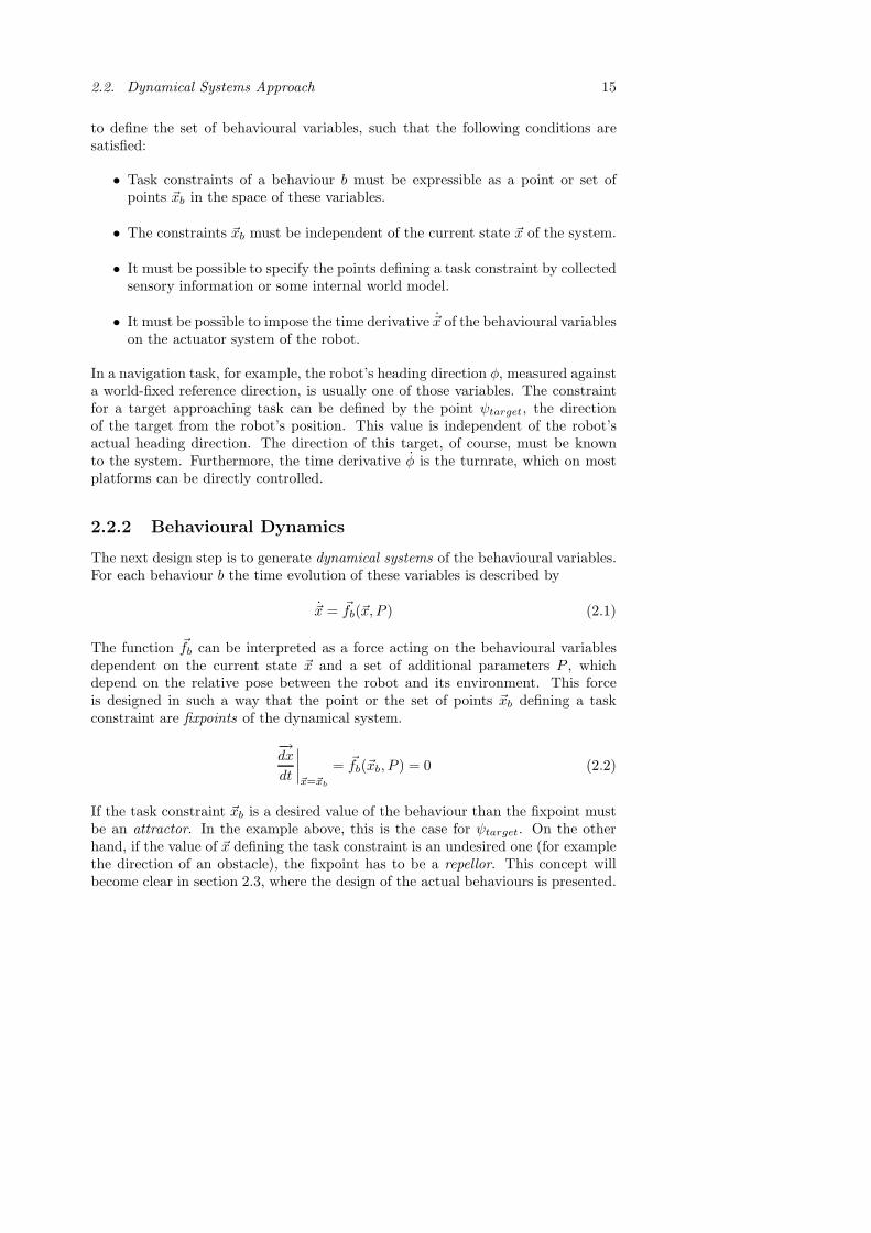
Let’s now define the angular range σi in the following way:
σi = arcsin(
1 + Ds
1 + di
)(2.14)
In Figure 2.6 it can be seen that the dynamics erects a repellor (σ >|ψi−ψj |
2 ), ifthe gap is too narrow for the robot to pass ensuring a safety distance Ds. On theother hand, if the gap is wide enough, an attractor is created (σ <
|ψi−ψj|2 ).
��������������������������������������������������������������������������������������������������������������������������������������������������������������������������������������������������������������������������������������������������
��������������������������������������������������������������������������������������������������������������������������������������������������������������������������������������������������������������������������������������������������
Ds Ds
i j
|ψ −ψ |i j2
σi
d i
��������������������������������������������������������������������������������������������������������������������������������������������������������������������������������������������������������������������������������������������������
��������������������������������������������������������������������������������������������������������������������������������������������������������������������������������������������������������������������������������������������������
Ds Ds
i j
d i
σi
|ψ −ψ |i j2
Figure 2.6. Illustration of the choice of σ. If the gap between the two obstacles
i and j is too narrow (left image) , σ is greater than|ψi−ψj |
2. Thus, a repellor is
created by the φ-dynamics (equation 2.13). If the gap is wide enough (right image),
σ <|ψi−ψj |
2holds, and an attractor occurs.
In this example, it can clearly be seen how decision making processes are mod-elled as bifurcations in the dynamical systems. As the distance between two obsta-cles changes, the amount and nature of the fixpoints is modified. A single repellor,which triggers turning away from the obstacles, becomes an attractor and two repel-lors as the distance between the obstacles grows. Hence, the latter situation makesthe robot passing the gap. Figure 2.7 shows a plot of the fixpoints dependent onthe distance Dobst between the obstacles. The safety distance was set to one robotradius. Thus the bifurcation occurs at Dobst = 4.
Corridor Following and Wall Avoidance
The behaviours corridor following and wall avoidance navigate the robotalong an empty corridor. Corridor following is expected to align the robots

2.3. System Design 23
0 1 2 3 4 5 6 7 8−0.8
−0.6
−0.4
−0.2
0
0.2
0.4
0.6
0.8
Dobst
φ
Figure 2.7. Repellors (solid line) and attractors (dashed line) of the φ-dynamicsdependent on the distance between two obstacles Dobst (see Figures 2.4 and 2.5).Units on the x-axis are multiples of the robot’s radius. The safety distance was setequal to 1. Thus, the bifurcation occurs at 4.
heading with the corridor direction ψcorr, which the robot is supposed to follow.Hence, the behavioural dynamics has the same form as for go to (equation 2.9).
φ = fcorr,φ(φ) = −λcorr,φ sin(φ− ψcorr) (2.15)
Wall avoidance is supposed to guide the robot towards the center of the corridor.Thus, for each wall the dynamics contains a repellor located at the direction ofthese walls, ψwall−1 and ψwall−2 respectively; and an attractor along the oppositedirection. The magnitude of the repellor should decrease with increasing distanceto the wall at a rate determined by a gain cwall > 0. The stronger contributionof the closer wall dominates the repulsive force of the remote wall in a way thatresults in a repellor generated along the direction of the former. Again, we requirethe function fwall to be 2π-periodic. These criteria are met by a dynamics of thefollowing form (Figure 2.8):
φ = fwall,φ(φ) = λwall,φ
2∑l=1
[sin(φ − ψwall−l) · e−cwalldwall−l
](2.16)
dwall−1 and dwall−2 denote the distances between the robot and each of the twowalls.
Door Passing
The behaviour door passing is supposed to lead the robot through a door. This isin principle the same as moving towards a goal in the direction of the door, ψdoor.

24 Chapter 2. Control System
φ
φ
ψ
ψwall−2
wall−1
0 2π
Figure 2.8. The dynamics of heading direction φ for wall avoidance. Each wallprovides a contribution (dashed curves) with an attractor repellor pair. The sum ofthe two contributions forms a repellor in the direction of the closer wall (ψwall−1 inthis case). An attractor occurs at the opposite direction ψwall−2.
Therefore, the same functional form as for go to (equation 2.9) was chosen:
φ = fdoor,φ(φ) = −λdoor,φ sin(φ− ψdoor) (2.17)
2.3.2 Dynamics of Speed
Before the definitions of the dynamical systems for the robot’s speed v are presented,an upper limit on this speed is established due to stability considerations. All theabove introduced dynamical systems fb,φ depend on an angle under which a certainobject (goal, obstacle, corridor, wall, or door) is perceived. Usually, this angleconstitutes a fixpoint in the dynamics of φ. However, it is changing its value, whilethe robot is moving through its environment. Hence, the fixpoints gradually movealong the φ-axis. The rate at which these points are shifting must be slow enoughfor the dynamical system to stay close to the attractor at all times. This constraintcan be fulfilled by choosing the maximum speed of the robot appropriately. Howthis is done is described in the following, taking the behaviour go to as an example.
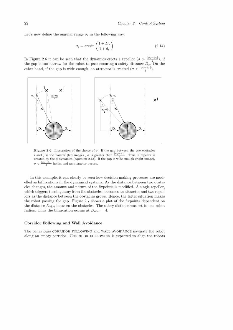
While the robot is moving an infinitesimal distance v dt the angle ψgoal, at whichthe goal point lies changes by dψgoal, which can be calculated in the following way(see Figure 2.9):
|dψgoal| ≈ | sin(dψgoal)| = | sin(φ− ψgoal)| · v dt
dgoal(2.18)
where dgoal is the distance from the robot to the goal point. During the same time,the robot’s heading φ changes by a value dφ due to its own dynamics defined inequation 2.9.
|dφ| = λgoto,φ| sin(φ− ψgoal)| dt (2.19)
In order to ensure that the behavioural dynamics stays close to an attractorstate at all times, the dynamics of φ has to take place on a faster timescale thanthe gradual shift of the angle ψgoto; which means |dφ| � |dψgoal|. This can be
2.3. System Design 25
������������������������������������������������������������
������������������������������������������������������������
�������������������������������������������������������
�������������������������������������������������������
v dt
goalψdd
goalφ−ψ
goal
goal
Figure 2.9. While the robot is moving a distance v dt through its environment, theangle to the goal point changes by dψgoal according to equation 2.18.
achieved by choosing the maximum speed dependent on the distance to the goalpoint.
v ≤ kgotodgoal where kgoto λgoto,φ (2.20)
Substituting this value for the speed in equation 2.18 shows that |dφ| � |dψgoal|holds. Hence, stability of the φ-dynamics can be achieved by choosing appropriatevalues for the constants λgoto,φ and kgoto. In other words, this is done by raisingthe strength of the attractor (increasing λgoto,φ) or by slowing down the platform(decreasing kgoto). These considerations must be taken into account in the designof the dynamics of speed for all behaviours, which are presented below.
Go To
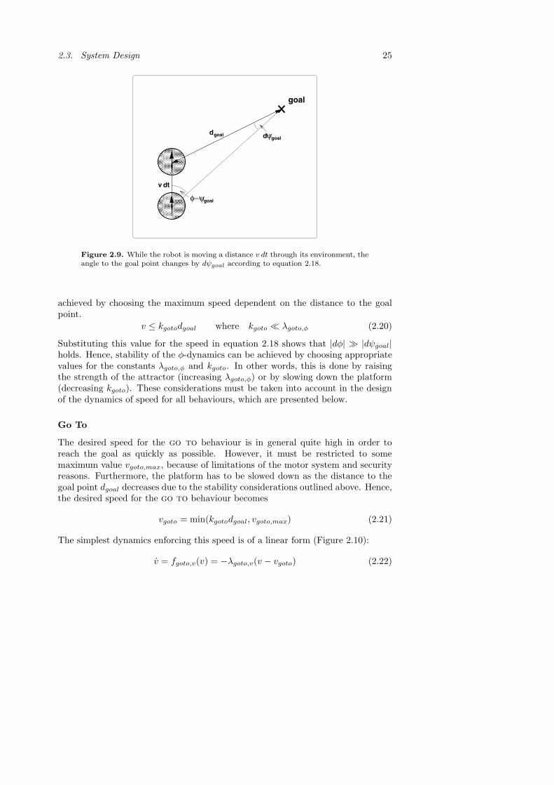
The desired speed for the go to behaviour is in general quite high in order toreach the goal as quickly as possible. However, it must be restricted to somemaximum value vgoto,max, because of limitations of the motor system and securityreasons. Furthermore, the platform has to be slowed down as the distance to thegoal point dgoal decreases due to the stability considerations outlined above. Hence,the desired speed for the go to behaviour becomes
vgoto = min(kgotodgoal, vgoto,max) (2.21)
The simplest dynamics enforcing this speed is of a linear form (Figure 2.10):
v = fgoto,v(v) = −λgoto,v(v − vgoto) (2.22)

26 Chapter 2. Control System
Also here, the strength of the attractor (equation 2.3) is defined by a constantλgoto,v > 0. This might look as the robot would be slowing down constantly as it isapproaching the target. However in reality, kgoto can be chosen high enough, suchthat the robot mostly drives at the speed vgoto,max. Only when coming very closeto the goal point, the platform is decelerating.
v
v0
vgoto
Figure 2.10. The dynamics of speed v for go to. At the desired velocity vgoto, anattractor is generated.
Also for this dynamics we have to make some considerations of the parametersto ensure that the dynamics stays close to an attractor state at all times. Theattractor vgoto is shifting due to a change in dgoal when the robot is getting closeto the goal point. If the robot is heading straight towards it, this change is at itsmaximum. In this case, the attractor moves by dvgoto during the time dt. Fromequation 2.21 we get
|dvgoto| = kgoto |ddgoal| = kgoto|v| dt (2.23)
During the same time the speed v is changing due the behavioural dynamics (equa-tion 2.22) by dv.
|dv| = λgoto,v |v − vgoto| dt (2.24)
The behavioural dynamics will converge to a point, where the attractor vgoto isrunning away at the same pace as v is approaching it. At this point |dvgoto| = |dv|holds. To guarantee that this point is close to the attractor state vgoto we must toassure the following:
kgoto
λgoto,v=
|v − vgoto||v| 1 hence: λgoto,v � kgoto (2.25)
In other words, choosing the strength λgoto,v of the attractor big enough, ensuresthat the system stays close to the attractor state vgoto.
Obstacle Avoidance
For the behaviour obstacle avoidance there are basically two constraints posedon the speed of the robot. On the one hand, it has to be above some slow constant

2.3. System Design 27
minimum speed vmin in order to keep moving and getting out of impasse situations.On the other hand, it must be below some maximum, which is decreasing as therobot gets closer to obstacles due to security reasons. For this maximum speeda linear dependency is chosen in the same way as in equation 2.20. These twoconstraints define a set of fixpoints as opposed to an isolated fixpoint, which wasthe case in all dynamical systems defined so far. Thus, the behavioural dynamicsof a single obstacle i is defined as follows (Figure 2.11):
fi,v(v) =
−λobst,v(v − vmin) for v < vmin
0 for vmin ≤ v ≤ kobstdi
−λobst,v(v − kobstdi) for v > kobstdi
(2.26)
di is the distance from the robot to obstacle i and the constant λobst,v > 0 definesthe strength of the attractive region. To assure that both the dynamics of φ andthe dynamics of v stay close to their attractor states, the same conditions as forthe go to behaviour (equations 2.20 and 2.25) must be satisfied.
λobst,φ � kobst and λobst,v � kobst (2.27)
v
vvmax
vmin0
Figure 2.11. The dynamics of speed v for obstacle avoidance for a single obstacle.The region between the two speed constraints vmin and vobst is attractive.
As in the case of the dynamics of heading direction (equation 2.11) individualobstacle contributions are added to define the dynamics of speed for obstacleavoidance.
v = fobst,v(v) =∑
i
fi,v(v) (2.28)
If we now combine two obstacles i and j at distances di and dj from the robot;with let’s say di < dj . The upper bound of the attractive region is kobstdi. Hencethe maximum speed is determined in a conservative fashion by the distance to thecloser obstacle as illustrated in Figure 2.12.

28 Chapter 2. Control System
v
v
vmin0 vmax1
vmax2
Figure 2.12. The dynamics of speed v for obstacle avoidance for two obstaclesat distances d1 and d2 from the robot (dashed lines). The overall dynamics (solidline) has an upper bound of the attractive region, which is determined by the closerobstacle (obstacle 1 in this case).
Wall Avoidance
For the behaviour wall avoidance the same arguments as for obstacle avoid-ance hold. Hence, each wall l contributes to the behavioural dynamics as follows:
fl,v(v) =
−λwall,v(v − vmin) for v < vmin
0 for vmin ≤ v ≤ kwalldi
−λwall,v(v − kobstdl) for v > kwalldl
(2.29)
The overall dynamics of the speed v for wall avoidance is obtained by summingthe two wall contribution as in the case of the φ-dynamics in equation 2.16.
φ = fwall,v(v) =2∑
l=1
fl,v(v) (2.30)
Also here the conditions on the strengths of the attractors must hold.
λwall,φ � kwall and λwall,v � kwall (2.31)
Corridor Following and Door Passing
As for the φ-dynamics, the dynamics of the robot’s speed v for the behaviourscorridor following and door passing have the same mathematical form asgoto (equation 2.22).
v = fcorr,v(v) = −λcorr,v(v − vcorr) (2.32)v = fdoor,v(v) = −λdoor,v(v − vdoor) (2.33)

2.3. System Design 29
The stability consideration presented at the beginning of this section do not applyfor corridor following, since the direction of the corridor ψcorr (equation 2.15)does not change as the robot moves. Hence, vcorr is constant. However, for doorpassing the distance to the door has to be taken into consideration analogously tothe distance to a goal point (equation 2.21).
vdoor = min(kdoorddoor, vdoor,max) (2.34)
vdoor,max is chosen rather small, since doorways are usually narrow. Finally, thesame conditions on the parameters as for go to (equations 2.20 and 2.25) must besatisfied, of course.
λdoor,φ � kdoor and λdoor,v � kdoor (2.35)
2.3.3 Behaviour Coordination
The overall dynamics of the system is obtained from the weighted summation ofindividual behaviours based on equation 2.4:
(φ
v
)=
∑b∈B
|wb|(fb,φ(φ)fb,v(v)
)+ noise (2.36)
with B = {goto, obst, corr, wall, door}. For the coordination of the behaviours,the competitive advantages αb, the competitive interactions γb′,b, and the timeconstants τb in the competitive dynamics of the weights wb (equation 2.5) must tobe chosen appropriately.
Competitive Advantages
The competitive advantages reflect the relevance and applicability of a behaviourin a particular context. Obviously, go to should be activated whenever the agentfinds itself in a room and is supposed to approach a goal; otherwise, it is turned off.For αgoto ∈ (0, 1] the behaviour go to is switched on (equation 2.6). To have thepossibility for any competitive interaction γb,goto ∈ [0, 1] to be greater or smallerthan αgoto, a value of 0.5 is chosen for the competitive advantage.
αgoto =
{0.5 if in a room−0.5 otherwise
(2.37)
Equivalently, corridor following and wall avoidance are relevant if the robotis in a corridor.
αcorr = αwall =
{0.5 if in corridor−0.5 otherwise
(2.38)

30 Chapter 2. Control System
The competitive advantage of door passing is set to a positive value as soon asthe door we want to pass is detected.
αdoor =
{0.5 if door detected−0.5 otherwise
(2.39)
The relevance of obstacle avoidance depends on the number and proximity ofthe obstacles currently surrounding the robot. Hence, the competitive advantage ofobstacle avoidance is related to the obstacle density ρ defined in the followingway:
ρ =∑
i
e−di (2.40)
and is computed according to
αobst = tanh(ρ− ρ0
ρ0
)(2.41)
The constant ρ0 determines the density above which obstacle avoidance becomesrelevant (i.e. αobst > 0). The tangent hyperbolic ensures that the magnitude ofαobst is limited to the interval [−1, 1].
Choosing the parameters in this way, depending on sensory and topologicalcontext, incorporates both behaviour arbitration and fusion. Arbitration is achievedbetween go to and corridor following, for example. Only one of the two isactivated depending on the location of the robot. Fusion occurs between go toand obstacle avoidance, for example, by adding the two contributions (equation2.36). In case an obstacle is blocking the way towards the goal point, the φ-dynamicsguides the robot around the obstruction and the v-dynamics slows the robot down(Figure 2.13).
Another example of behaviour fusion is the combination of obstacle avoid-ance and wall avoidance. When the robot is travelling along a corridor con-taining obstacles the safety distance Ds (introduced in section 2.3.1) has to be keptto all obstructions. Thus, if a gap between an obstacle and a wall is wide enoughthe dynamics should create an attractor in the direction of this gap. So, similarconsiderations as in the case of two obstacles have to be made (see Figures 2.4and 2.5). This poses some constraints on the decay factors cobst and cwall, andthe strength of the slopes λobst,φ and λwall,φ. However, solving the mathematicalequations is somewhat more complex than in the case of two obstacles (equations2.12 and 2.13). Hence, the relation of the parameters was determined numericallyin order to achieve the desired behaviour.
Competitive Interactions
The competitive interaction γb′,b reflects the degree to which an active behaviourb′ suppresses another behaviour b. In fact, there are situations where behaviourswould interfere with each other in an undesirable, counterproductive manner.

2.3. System Design 31
���������������������������������������������������������������������������������������������������������������������������������������������������������������������������������������������������������������������������������������
���������������������������������������������������������������������������������������������������������������������������������������������������������������������������������������������������������������������������������������
obst
goal
goalψobstψ 20 π
φ
φ
minv vmax
gotov0
v
v
Figure 2.13. Fusion of go to (dotted curve) and obstacle avoidance (dashedcurve). Adding those two contributions gives the overall dynamics (solid curve).For the heading direction φ an attractor is created, which lies on the left of thegoal direction ψgoal. For the speed v the attractor lies close to vmax of obstacleavoidance in order to slow down the robot.
A door that is half-blocked by an obstacle might still be detected as a door,although the gap to pass is actually too narrow. Hence we want obstacle avoid-ance to suppress door passing in the presence of a high obstacle density. Fur-thermore, if two obstacles lie close to each other, the dynamics of φ generates aweak repellor in the middle of them. This repellor, however, could be dominated byan attractor of another behaviour, which would inevitably lead to collision (Figure2.14). Consequently, a behaviour arbitration mechanism is needed, where obsta-cle avoidance ought to suppress go to and corridor following as well, if theobstacle density (equation 2.40) exceeds a critical threshold ρc. This prioritisationis achieved by appropriately choosing the competitive interactions:
γobst,goto = γobst,corr = γobst,door =12
(1 + tanh
(ρ− ρc
σρ
))(2.42)
The constant ρc determines the density at which obstacle avoidance suppressesthe other behaviours (γobst,b > 0.5). The width σρ defines the size of the regionaround ρc, where obstacle avoidance influences the degree of activity of the

32 Chapter 2. Control System
goal
ji
sDsD
������������������������������������������������������������������������������������������������������������������������������������������������������������������������������������������������������������������������������������������������������������
������������������������������������������������������������������������������������������������������������������������������������������������������������������������������������������������������������������������������������������������������������
φ
φ
0
π2
goalψ
Figure 2.14. The contribution of two close obstacles i and j (dashed line) has arepellor in the middle of them (compare to Figure 2.4). However, this rather weakrepellor is dominated by the attractor of go to (dotted line, see Figure 2.2). Hencethe sum of the two (solid line) would ignore the obstructions. An arbitration schemeis needed to prioritise obstacle avoidance.
other behaviours (without switching them off yet). The functional form of theterm is chosen such that γobst,b ∈ [0, 1]. Since there exist no potential conflictsamong any other pair of behaviours, all other competitive interactions γb′,b are setto zero.
Through this competition, another example of decision making by bifurcationsis illustrated. This time in the dynamics of the weights wb. Consider the situationdepicted in Figure 2.14, for example. When the obstacle density is low, the weightwgoto possesses two attractors at ±1 and a repellor at 0. Thus, the behaviour go tois switched on. Then, as the robot approaches the obstacles, the obstacle densityρ increases, and so does the competitive interaction γobst,goto. When it exceedsthe value of αgoto (0.5), a single attractor for wgoto is created at 0. Hence, at thebifurcation a decision is made by the system, and the navigational strategy changescompletely. Figure 2.15 shows a plot of the fixpoints of wgoto dependent on theobstacle density ρ. The critical density ρc was set to 0.5. Thus, this is the valuewhere the bifurcation occurs.
Time Constants
The time constants τb determine the time scale at which the behaviours are switchedon and off. τobst is chosen very small, such that the robot reacts almost immediatelyif a new obstacle is perceived. The same holds for τwall. As soon as a door isdetected, the robot should turn towards it before driving out of detection rangeagain. Consequently, τdoor is also chosen to be small. The dynamics of wgoto andwcorr evolve at a slower rate τgoto = τcorr � τobst. Once obstacle avoidancebecomes less relevant (for example, when the robot is about to clear an impassesituation) the other behaviours switch on gradually. This often prohibits the robot

2.4. Discussion 33
0 0.2 0.4 0.6 0.8 1
−1
−0.5
0
0.5
1
ρ
wgo
to
Figure 2.15. Repellors (solid line) and attractors (dashed line) of the wgoto-dynamics dependent on the obstacle density ρ (equation 2.40). The critical densityρc was set to 0.5. Thus, this is the value where the bifurcation occurs.
from driving back towards the same obstructions (see the results in section 4.2).Moreover, the slow time scale of these behaviours avoids jitter among themselvesand obstacle avoidance.
2.4 Discussion
The dynamical systems approach has been chosen as the framework for the be-haviour based control system. Five behaviours were defined motivated by thegeneral structure of an indoor environment: go to, obstacle avoidance, cor-ridor following, wall avoidance, and door passing. The individual taskconstraints could be mathematically formulated and were expressed as fixpointsin the dynamics of the heading direction φ and the speed v. Through theoreticalanalysis of the fixpoints, additional constraints could be incorporated, which deter-mine the occurance of bifurcations. These bifurcations express decision making onthe reactive level as seen in the case of two obstacles. Furthermore, the behaviourcoordination scheme has been exploited. The robot’s current context influencesthe parameters in the competitive dynamics, which activates and deactivates thebehaviours on different timescales. It has also been shown how both arbitrationand fusion can be achieved deploying this scheme.
The design of the dynamical systems for the control of heading direction followsclosely (Bicho and Schoner, 1997) and (Bicho et al., 2000). In addition to theirwork, the speed control is fully integrated here. In earlier studies, this quantityis, usually, set to a constant value. This assumption actually violates the method-ological constraint that the system must remain close to an attractor state at all

34 Chapter 2. Control System
times. Through the integration of the speed, this deficiency could be tackled asillustrated by the stability considerations in section 2.3.2. Another novelty of theimplementation presented here, is the use of the dynamical systems approach forrealistic real-world tasks. As opposed to simulation studies or the use of real robotson the small scale, the design as set forth here allows a system to navigate in alarge-scale environment through appropriate behaviour switches. The integrationof this arbitration mechanism into the competitive dynamics assures a smooth con-trol of the platform. Whereas in other frameworks (for example, discrete eventsystems), discrete behaviour switching is applied, which results in an instantaneouschange of the control strategy.
The dynamical systems approach is often compared to potential field methods.In that framework, individual behaviours also erect vector fields, whose weightedsuperposition determines the control action of the robot. However, the two ap-proaches are very different in nature. In the potential field method, the vectorfields are defined in the physical space. Their values determine the direction inwhich the platform should move at each point. The attractor of this field is thegoal point, where the system ends up after completing its mission. In the dynamicalsystems approach, however, the vector field is defined in the space of the behaviouralvariables. This field is dynamic and changes as the robot moves about its environ-ment, while the system is close to an attractor state at all times. These differencesbecome obvious, when individual behaviours are combined. In the potential fieldmethods, weighted averaging of the desired moving directions is the only possibilityof behaviour combination. Whereas a much richer form of fusion is possible in thedynamical systems approach, since the attractor of the superposition can, basically,be everywhere in the space of the behavioural variables (compare Figures 2.4, 2.5,2.12, and 2.13).
The dynamical systems approach was also used in other forms and for other tasksas presented here. Bicho and Schoner (1997), for example, chose the turnrate asbehavioural variable in order to simulate phototaxis. Moreover, in (Schoner et al.,1995; Steinhage and Schoner, 1997) the common use of behaviour was stretcheda bit by designing modules for ego-position estimation, for example. In addition,dynamic fields were used to define representations of the environment (Engels andSchoner, 1995). This was integrated with the dynamic systems for control intoone coherent framework for a robotic system (Schoner et al., 1995). However,the use of dynamic fields for representing objects in the platform’s surrounding,is computationally expensive and, therefore, not suited for real-world applications.Furthermore, the integration of planning in such an architecture is rather unclear.Hence, these extension of the approach have not been used in the work of this thesis.How such representations of the environment can be integrated into the system isthe topic of the next chapter.

Chapter 3
Representations
In order for a control system to work in the real world, it needs to relate to geomet-rical and symbolic representations of the environment. The two terms, geometricalrepresentation and symbols are closely related and often overlapping. Geometricalrepresentations are typically used to determine the parameters in a control system.These representations range from simple measurements like distances to obstaclesto more complex models of the world including specific features and maps. Sym-bols, on the other hand, is a term frequently used in AI. Decision making processesare usually based on symbols, which stand for labelled entities in the world.
For a navigation system, it can easily be seen that there is no clear distinctionbetween these two terms. Two obstacles in the robot’s path can be viewed assymbols, based on which the system makes a decision of passing between them oravoiding the gap, as illustrated in section 2.3.1. The properties of these symbols (forexample their distance to the robot) are a geometrical representation of the currentsituation. Furthermore, a map of the whole area in which the system operates isa geometrical representation of the environment. However, this map can containfeatures of a symbolic nature, which are used to make decisions dependent on thenavigation strategy. Hence, the terms are often used interchangeably in roboticsliterature. However, one problem has to be solved by all designers of robotic systemsacting in the real world. How can information obtained by sensors be transformedto symbolic representations of the system? This process is commonly referred toas symbol anchoring. A general framework in the context of hybrid deliberativesystems is proposed here. Its functionality is illustrated through the implementationof the indoor navigation system.
This chapter is organised in the following way. In section 3.1, a brief overviewon geometrical representations for navigation systems is given. Further, the mapused in the studies of this thesis is presented. Then, in section 3.2 the anchoringproblem is discussed and the general framework is presented. The details on allthe symbols of the navigation system and their anchoring processes is presented insection 3.3. The chapter concludes with a summary and discussion in section 3.4.
35

36 Chapter 3. Representations
3.1 Geometrical Representations
Geometrical representations used by mobile robot navigation systems can roughlybe divided into two categories: representations of individual objects close to therobot and maps reflecting the large-scale structure of the environment.
3.1.1 Local Representations
For mobile robots, local representations facilitate safe and precise navigation takinginto account the small-scale structure of the platform’s surrounding. Typically,these structures are directly extracted from sensory data. Hence, in a behaviourbased approach, the extracted properties are, usually, directly fed to the individualbehaviours, such that these modules can also react to unexpected events. The exacttype of representation used by a system is highly dependent on the task at handand the sensing capabilities of the robot. Thus, there are almost as many differentimplementations as there are robotic systems, and to give a complete overview israther impossible. However, some commonly used strategies are summarised below.
The most common type of sensor used in navigation tasks is a range sensor:sonar or laser scanner. Based on the time of flight of an ultrasonic pulse or a laserbeam respectively, an estimate to the closest object in the direction of the sensorcan be obtained. This information can, of course, easily be used by an obstacleavoidance module. The properties of such an obstacle representation are mani-fold. In purely behaviourist approaches the estimate of the distance is directlyused without further processing (Braitenberg, 1984; Brooks, 1986). A more com-plex and commonly used representation is the vector field histogram introduced byBorenstein and Koren (1991). This method allows to determine the properties ofobstacles more precisely, taking into account the physics of the sensor and usingmultiple readings over time. Nevertheless, it has been shown to be computationallyfast enough to work in real time. Range sensors are further commonly used todetect landmarks (Wijk and Christensen, 2000), walls (Forsberg et al., 1995), andother geometrical features of the robot’s environment.
Another widely used sensor is a camera. An image of the robot’s surroundingcontains, of course, much more information than a sonar or a laser scan. This ad-vantage, however, makes the extraction of representations also more complex. Theresearch field of computer vision (Gonzales and Woods, 1992) is dealing with thisproblem of detecting objects in pictures. These techniques have successfully beenapplied to obstacle avoidance (Kosecka et al., 1995) and visual servoing (Hutchinsonet al., 1996), for example.
In the work of this thesis a robot equipped with a ring of 16 sonars (see section4.1) has been used. In order to allow safe navigation and dealing with local tasks,different geometrical representations are extracted from the sensory data: obstacles,corridors, and doorways. For the detailed properties and anchoring mechanisms ofthese objects see section 3.3

3.1. Geometrical Representations 37
3.1.2 Maps
Maps represent, usually, the large-scale structure of an environment. They areessential for a mobile robot in order to reach a goal, which is far away and can notbe detected by any sensors initially. Maps often constitute the a priori knowledgethe system possesses about the environment. However, they can also be builtor updated by sensory data. In general, maps can be divided in two categories:geometrical and topological maps. These two types are introduced below. Then,the map used in these studies is presented, which is a topological with some minimalgeometrical properties.
Geometrical Maps
Geometrical maps are a rather detailed representation of an area. They are rich oninformation, which makes them convenient to use for navigation purposes given agood estimate of the robot’s position. However, the large amount of informationposes constraints on the storage capacity of a system. Further, this maps are ratherhard to construct due to their detailed description of the environment. There aretwo main types of these large-scale representations: grid maps and feature maps.
A grid map divides the environment in many equally large cells of square shape.Each of these cells holds a number reflecting the probability that it is occupied.Occupied, here, means that anything could be there: a wall, a smaller obstacle,or even a person. Since there is no distinction of different objects, range sensorsare the optimal choice for creating and using grid maps. Moravec (1988) and Elfes(1987) were the first to employ such a map for navigation purposes and, later, forpath planning (Elfes, 1989). These approaches make use of a detailed sensor modeland Bayesian statistics to update and use the map. These methods are widely usedtoday and they have been further refined by applying more accurate sensor models(Konolige, 1997) and other forms of reasoning (Pagac et al., 1998).
A feature map reflects not only the occupancy of cells, but contains also in-formation about the actual objects occupying the locations. This representationconsists of features and their coordinates in the environment. These features areoften lines (Crowley, 1985) or general geometric beacons like points, corners, andwalls (Leonard and Durrant-Whyte, 1991), which are extracted by range sensors.The complexity of a feature map can vary from minimalistic models containing onlywalls (Jensfelt and Christensen, 2001) to a complete CAD model of the environ-ment as in (Christensen et al., 1994). This type of maps have been widely used fordifferent robotic applications. Many refinements have been developed like learningthe features with artificial neural networks (Thrun, 1998) or tracking hypothesisabout them over time (Arras et al., 2003).
Topological Maps
Topological maps reflect the large-scale structure of an environment containing in-formation of low complexity. The space is segmented into topological units (places)

38 Chapter 3. Representations
and the connectivity of these units is given. Such a map is, mostly, representedby a graph structure with nodes standing for important places in the environmentand edges defining how this places are connected. These types of maps are verycompact representations and are, usually, easy to construct due to their low com-plexity. Another advantage of these maps is that they only contain informationwhich hardly changes over time (rooms or corridors). Hence, they are still validafter, for example, refurnishing an office space. However, they are harder to use fornavigation purposes than metric maps, because only limited knowledge about therobot’s surrounding is available.
Kuipers and Levitt (1988) were one of the first using this concept. They defineda cognitive map on several levels of abstraction, where one of these levels wastopological. They further extended their approach to learning a spatial semantichierarchy of an area (Kuipers et al., 1993). Horswill (1998) constructed a systemusing a topological map specifically for office environments assuming angles of 90◦
between all corridor parts. Corridors can also be divided into large cells, where eachcell defines a topological unit as done for the indoor navigation systems Dervish(Nourbakhsh et al., 1995; Nourbakhsh, 1998) and Xavier (Koenig and Simmons,1998), for example.
Since these types of maps lack a lot of geometrical information, they are oftencombined with metric maps. One way to do this is defining some hierarchy ofinformation in the environment (Kuipers and Levitt, 1988; Poncela et al., 2002).Another way is to divide a grid map into distinctive parts and defining their topo-logical relation (Fabrizi and Saffiotti, 2002). In Tomatis et al. (2003) only theinteresting parts of the environment are mapped geometrically while others (forexample corridors) have a pure topological representation.
The Topological Map in these Studies
The map chosen for the navigation system presented in this thesis is almost purelytopological. The main structure contains qualitative information about the large-scale connectivity of the environment. This information is reflected in a graphstructure containing nodes and edges that connect these nodes. The nodes standfor important places in the environment and locations where a change in the navi-gational strategy occurs. Hence, there has to be one in front of each door, at eachcorridor crossing and at other places of interest (for example, goal locations andcharging station). Each node has a location in a fixed coordinate system. The edgesthat connect these nodes can be of three different types: room, corridor, door. Dueto the limited amount and simplicity of information in this map, it is a matter ofminutes to construct a new one for a previously unknown domestic environment.
Figure 3.1 shows the map of our institute. As can be seen, it is topologicalin nature. Nevertheless, it also contains some minimal geometrical informationreflected in the properties of the different nodes, which defines their location in theworld. Figure 3.2 shows more details on the placement of these nodes. Nodes incorridors are in the middle of the two walls. The ones in front of doors are aligned

3.1. Geometrical Representations 39
Figure 3.1. The topological map of our institute: The circles depict nodes, whichhave a location in a coordinate system. Edges are of three different types: corridor(thick line), room (dashed line), and door (thin line). Additional nodes for goalpoints and starting positions can be added arbitrarily.
�������
�������
�������
�������
��������������������������������
d d
d
d
d d
1
2
2
3 3
1
����������������������������������������������������������������������������������������������������������������������������������������������������������������������������������������������������������������������������������������������������������
��������������������������������
������������������������������������������������������������������������
����������������������������������������������������������������������������������������������������������������������������������������������������������������������������������������
������������������������������������������������������������������
������������������������������������������������������������������
����������������������������������������
����������������������������������������
������������������������������������������������
������������������������������������������������
����������������������������������������
����������������������������������������
����������������������
����������������������
��������������
Figure 3.2. Placement of the nodes of the topological map. A schematic drawingof a corridor and two doors leading to rooms. The nodes (depicted by circles) areplaced, such that they are centred in the corridor and between the door posts.
with the centre between the door posts. Further, nodes in rooms are positionedat places that are important for the navigational task. This placing allows thenavigation system to effectively keep track of its position and orientation (see section3.3.2). Nevertheless, these coordinates need not to be very accurate, because thenodes in combination with the robot’s position estimate are only needed for taskswitching. Whereas guiding the robot through a door, for example, is controlled

40 Chapter 3. Representations
by the behaviours which extract the precise location of the door posts from sensorydata. Note that there is some redundancy in placing some of the nodes. Thedistance of a door node in a room (on the top in Figure 3.2) to the actual doorwaydoes not really matter as long as it is not more than about 2 meters. Also theposition of a goal point does usually not have to be precise, because the controllersof the tasks to be executed at this goal point can compensate for that with theirsensing capabilities. For example, visual servoing can guide the robot accurately infront of a table in order to pick up an object.
3.2 Symbol Anchoring
Symbols are discrete entities labelled with a name. They are, in general, extractedfrom sensory data and a predefined world model. Symbols are used for decisionmaking, which refers to choosing one out of several control strategies, which leadto qualitatively different behaviour. In the dynamical systems approach, thesedecision making processes are implicitly modelled in the control laws through theuse of bifurcation. Let’s recall two examples from section 2.3. The gap between twoobstacles influences the amount and nature of fixpoints in the dynamics of headingdirection (Figure 2.7). Further, in Figure 2.15, it can be seen how an increasingobstacle density alters the fixpoints of the competitive dynamics of the weight wgoto,which leads to a task switch.
The process of relating the symbols to sensory data and the world model iscommonly called symbol anchoring. Some general considerations to this problemsare discussed in section 3.2.1. Then, in section 3.2.2, a general framework foranchoring in hybrid deliberative architectures is presented.
3.2.1 Introduction
The signal to symbol transformation is a long standing problem in artificial intelli-gence. The question is related to the issue of selecting information from a stream ofincoming data. The problem has been addressed in AI in general and many relateddomains such as computer vision (often referred to as figure-ground segmentation)and robotics (mapping). Others have avoided the problem by specifying that ev-erything is a symbol (Simon, 1981). For construction of real-world systems suchas mobile robots it is, however, important to consider the relation between percep-tual data and symbolic models of such percepts. In addition to the extraction ofsymbolic information, it is further necessary to consider the maintenance of suchsymbols over time. As part of this an obvious question is: when and how doesone need to perform the anchoring of symbols and maintain their consistency overtime? This is the issue addressed here in the context of mobile robotic systems. See(Coradeschi and Saffiotti, 2003) for a broader description of the general problem.
All designers of robotic systems acting in the real world have, of course, solvedthe anchoring problem in some way. However, it was performed on a system by

3.2. Symbol Anchoring 41
system basis without a general methodology and explicit treatment of the problem.Hence, the anchoring processes are, usually, hidden somewhere in the code of theprograms controlling the robots. Nevertheless, a general framework would be usefulas a design methodology and, further, facilitate comparison of different systems.A first attempt to such a general framework has been outlined in (Coradeschiand Saffiotti, 2000) and extended in (Coradeschi and Saffiotti, 2001). Here, theanchoring is placed in a system context as seen in Figure 3.3. Sensory readings aretransformed into symbolic information that can be used by a planner and a controlsystem that transforms this information into specific signals carried out throughthe actuation system. In addition, the planner makes use of a world model thatcontains a priori information about the environment.
PlannerWorld Model
Anchoring Symbols Control SignalsControlSensory Signals
Figure 3.3. Information flow in a general control system.
The anchoring problem can be considered as three sub-problems:
1. Is the symbol to be extracted present at all (recognition/detection)
2. What are the exact properties of this percept(description/parameterisation)
3. How can the representation be updated over time (tracking)
In a general context, the problem of recognition or figure ground segmentation isconsidered to be NP-hard. The prototypical example being the Marr paradigm pro-posed in computer vision (Marr, 1982; Tsotsos, 1990). Through consideration oftask constraints and careful selection of an appropriate control paradigm it might,however, be possible to convert the problem into a tractable one. An excellentexample of how robotics problems can be made tractable is the use of active per-ception, in which task constraints are used for selection of sensory information andcontrol of the associated processes, as described by (Aloimonos, 1993; Bajcsy, 1988)
As outlined in chapter 2, a lot of robotic systems today use a hybrid deliberativearchitecture, with a deliberative and a reactive part. The use of symbolic infor-mation across these two types of systems is different in the sense that the reactivesystem uses temporally local and precise information, while the deliberation part isdependent on global and contextual information. Consequently, the processing andhandling of anchoring can be divided into two parts in terms of detailed anchoringand maintenance over time. Through adaptation of such an approach, it is possibleto reduce the problem complexity considerably.

42 Chapter 3. Representations
3.2.2 The Proposed Framework
In a hybrid deliberative system architecture (see section 2.1 for an introduction)the control of the robot is divided into two different levels: a reactive level and adeliberative level. On the reactive level control solutions to single tasks are imple-mented in behaviours. These behaviours solve their tasks based on representationsthat are closely related to immediate sensory input. The deliberative part of sucha system is responsible for generating a list of tasks to be accomplished in orderto achieve goals. Then, this plan has to be executed, which means the system hasto switch between individual tasks. In essence, this level of control is responsiblefor the coordination of the different behaviours. In addition to sensory data, thiscoordination scheme makes use of a world model to create the plan and monitor itsexecution.
Both levels in such an architecture contribute to the control output of the systemand include some type of decision making. Hence, they both have to deal withthe problem of anchoring: creating and maintaining the correspondence betweenpercepts (sensory information) and internal symbols. Here, it is proposed that theanchoring processes should be clearly distinguished for these two levels. By doingthis, the symbol anchoring problems become easier in each of the two levels than itis in a general framework (Figure 3.3). This is due to the fact that not all the threeproblems identified in the introduction (section 3.2.1) have to be solved for eachof the two parts. In addition, the extracted symbols from one level can be usedby the anchoring processes of the other one. The proposed system organisation isdepicted in Figure 3.4.
Reactive Level
Symbols Coordination
BehavioursSymbolsAnchoring
Control SignalsSensory Signals Integration
Anchoring
PlannerWorld Model
Deliberative Level
Figure 3.4. The proposed organisation for anchoring on different levels of abstrac-tion.
Anchoring on the Reactive Level
The reactive part has the purpose of dealing with immediate tasks at hand throughwell defined behaviours. This undertaking requires its own special type of symbols

3.2. Symbol Anchoring 43
and, thus, its own type of anchoring processes. Let us return to the three prob-lems that a general anchoring process has to solve (section 3.2.1), viewed in theperspective of reactive control:
1. The question if a symbol is present at all in the sensory data does often nothave to be addressed here. It can be answered by symbols at the deliberativelevel, since those are used for behaviour sequencing and and supervision ofplan execution. In consequence, the symbols at the deliberative layer canselect anchoring processes at the reactive level.
2. The question about the precise properties of a symbol has to be answeredon this level. These properties are needed by the behaviours for the systemto react in an appropriate fashion. For example, the location of obstacleshave to be extracted accurately in order to avoid collisions, or the dimensionsof an object to grasp have to be determined to allow visual servoing. Sym-bols at this level are, thus, predominantly specification of end-conditions andparameterisation of control.
3. The problem of maintaining the connection between a physical entity andan internal symbol of the system over time is of secondary importance atthis level. Reacting to immediate sensory input is the main intention of be-haviours, while maintaining connections to symbols over time and reasoningabout them is of limited relevance to the reactive control structure. For ex-ample, properties of obstacles need only be maintained in a limited sense overtime, as avoidance can rely on temporally local models and not necessarilyon strict maintenance of information about the relevant entities.
Anchoring on the Deliberative Level
The deliberative part has the purpose of creating global plans and supervise the ex-ecution of such plans. This requires access to context information that situates theplan in the physical world, which is achieved through detection of certain events.This involves recognition of “locations” and “situations”, which allows the deliber-ative layer to detect the completion of a particular task. This undertaking requiresdifferent types of symbols than the ones of the reactive level and thus different typesof anchoring processes. Again, let us return to the three problems that a generalanchoring process has to solve (section 3.2.1), this time viewed in the perspectiveof deliberative control:
1. The question if a symbol is present at all in the sensory data has to beanswered on this level (recognition), since the tasks to be executed dependheavily on this information. This problem is often hard to solve in a generalanchoring process. However, it becomes easier for “simple” symbols like con-text information, which is often the type of symbols used by a deliberativemodule.

44 Chapter 3. Representations
2. The question about the precise properties of a symbol is often less importanthere. A task coordination scheme does not need to know the exact propertiesof, for example, a box to pick up or an obstacle to avoid. These problems arehandled by the behaviours in the reactive layer.
3. The problem of maintaining the connection between a physical object andan internal symbol of the system over time is of major importance here. Tobe able to reason about objects and to keep track of a plan execution, theanchoring process needs to provide this feature of updating the properties ofsymbols over time (maintaining a model of the environment). Since theseproperties are, usually, of a less complex nature than the symbols at thereactive level, the problem of keeping track of them is simplified. In addition,the precise properties of the symbols on the reactive level can often provideuseful information to update the properties of the context symbols of thislevel.
The main advantage of the proposed separation is that the anchoring processesbecome easier to solve than in a general framework. Only a part of the threeproblems of a general anchoring process has to be attacked on each individual level.The reactive one can focus on the second question of extracting exact properties.The deliberative level, on the other hand, can work on information about contextand solving problems one and three for these “simpler” symbols. Through thisdistribution of the anchoring problem the complexity of a general perception processcan be decreased significantly.
3.3 Implementation
To illustrate the abstract organisation proposed above, the actual implementationfor the navigation task in indoor environments is presented. The symbols (andtheir properties) of the system are, eventually, used by the behaviours and thecoordinator to produce appropriate actuator signals as defined in section 2.3. Thetask at hand is navigation A → B. Typically A is the recharging station and Bcan be a number of intermediate points to be traversed as part of a surveillance ordelivery mission. The size of the environment is chosen to be a large area (20×70meters, see section 4.1). If the battery level at anytime goes below a critical level,the mission is to be aborted and the robot is to return to a recharging station. Thetask was designed to allow the robot to:
• Perform navigation to known positions (recognition of places through anchor-ing at the deliberate level)
• Handle obstacles (react to unexpected situations, which requires identificationof “situation” and switching of control)
• Handling of “system critical” events (requires abort of mission and replanningto achieve arrival at the recharge station)

3.3. Implementation 45
• Navigation involves several different settings (rooms, doorways and hallways)each of which calls for different types of control.
This setup allows to illustrate anchoring at the reactive and the deliberative layer,and for signalling across the two layers. Further, sensory signals are provided byultrasonic sensors, wheel encoders (odometry), and a voltage meter at the batteries(see section 4.1 for a detailed description of the robot and its sensors). In addition,the topological map introduced in section 3.1.2 is used as the world model of theplanning module.
The actual control schemes have been presented earlier in this thesis (section2.3). On the reactive level, each of the behaviours defines a dynamical system inthe form of equation 2.8. The parameters of these controllers (fb,φ and fb,v) areprovided by the symbols on the reactive level. A weighted summation of all be-haviours (equation 2.36) is, then, applied to the robot’s actuators. The weights usedin this aggregation are determined by the competitive dynamics of equation 2.5.The symbols on the deliberative level specify the parameterisation for this coordi-nation framework. In other words, the competitive advantages αb and competitiveinteractions γb′,b are determined.
Figure 3.5 shows the navigation system in the structure of the organisationproposed in this thesis (compare to Figure 3.2.2). Below, we go into the details ofthe symbols used and their anchoring processes, separately for the reactive and thedeliberative level.
Anchoring
Deliberative Level
Anchoring
Reactive Level
summation
− wall avoidancefollowing
− corridor− go to
− door passing− obstacle
avoidance− obstacles− doors− walls− corridors− goal points
topological map
context− sensory
context− topological− pose
Planner
− odometry− voltage meter
− sonars − rotational
− translationalspeed
speed
dynamicscompetitive
Figure 3.5. The organisation of the navigation system following the generalmethodology proposed in Figure 3.4.

46 Chapter 3. Representations
3.3.1 The Reactive Level
On the reactive level safe navigation has to be assured taking into account the localproperties of the environment. Recall section 2.3, where five behaviours have beendesigned to achieve this: go to to reach a given goal point, obstacle avoidanceto avoid collision with any kind of obstruction, corridor following and wallavoidance to navigate along a corridor, and door passing to traverse an opendoor. Each of these behaviours, defined by the dynamical systems fb,φ and fb,v,has its parameters based on the properties of some symbols. In the following, weintroduce all these symbols and their anchoring processes. Remember that here, onthe reactive level, the information if a certain object is present at all is usually givenby the deliberative level of the system. The symbol topological context of thatlevel determines at what time the anchoring processes described below are invokedat all. The only exception are obstacles, which are extracted from the sensorydata at every control cycle. Then, the importance of these processes is to obtainprecise information about the physical entities to allow safe navigation. Further,the problem of maintaining these properties over time is neglected here as motivatedin the general framework (section 3.2.2), which means that the behaviours rely onlyon temporally local properties. All the symbols and their associated properties forthe reactive level are summarized in Table 3.1.
Symbol Propertiesgoal point direction, distancecorridor direction, distance to wall 1, distance to wall 2wall direction, distancedoor detected, directionobstacle direction, distance
Table 3.1. The symbols of the reactive level.
Goal Point
The symbol goal point is used by the behaviour go to. This is the only symbol onthe reactive level that is not anchored using the sonar sensors. Its direction relativeto the robot is determined using the symbols pose and topological contextfrom the deliberative level introduced later in section 3.3.2. pose provides an esti-mate of the robot’s position and topological context provides the coordinatesof the next node (the goal point in this case) of the topological map (introduced insection 3.1.2). Then, the necessary parameters can easily be calculated.
The direction of the goal point relative to the robot, φ − ψgoal, is used bythe dynamics of heading direction fgoto,φ (equation 2.9), while the dynamics ofspeed fgoto,v (equations 2.21 and 2.22) makes use of the distance, dgoal from therobot to this point. There are no further properties to be determined for a goal

3.3. Implementation 47
point. However, in future implementations a certain object (for example a tableor a person) could be considered a goal point. Then, there could be a need of anadditional process to determine the properties of this object.
Obstacle
The symbol obstacle is used by the behaviour obstacle avoidance. Due to thelimited angular resolution of sonar sensors, this symbol relies on a rather simplegeometric representation that is closely linked to the actual perception of the robot.Out of the 50 most recent sonar readings that do not belong to detected walls(see symbols corridor and wall below), the ones in the frontal half plane ofthe current robot heading are considered. Obstacles are reconstructed from thesedetected echos in ascending order of their distance to the robot. The echo closest tothe robot defines the first obstacle whose orientation in the robot frame is given bythe axis of the sensor that received the echo. A new obstacle is recorded for everysubsequent echo whose orientation differs by an angle of at least 22.5◦ from anypreviously identified obstacle. New obstacles are added in an incremental fashionuntil the sonar buffer contains no further echos.
For each obstacle i, the dynamics of heading direction fi,φ (equations 2.10 and2.14) uses the angle ψi and the distance di as parameters. Further, the dynamicsof speed fi,v (equation 2.26) is dependent on the distance to the obstacle. Notice,that our representation only considers the direction and distance to an obstaclebut ignores its shape and size. Despite its simplicity, the chosen representationis powerful enough to successfully navigate in cluttered areas (see the results inchapter 4).
Corridor
The symbol corridor is used by the behaviours corridor following and wallavoidance They are based on the orientation of the corridor and the distance toits walls. To obtain this information the 200 most recent sonar readings are keptin a FIFO buffer. A Hough transform (Forsberg et al., 1995) is invoked on thesonar data every five seconds in order to extract the pair of parallel lines (one oneither side of the robot) that coincide with the largest number of sonar echos. Noassumptions on the width or direction of the corridor are made.
From these lines, the properties of a corridor can be determined: its directionψcorr, the direction of the two walls ψwall−1 and ψwall−2, and the distance fromthe robot to these walls dwall−1 and dwall−2. These parameters define the form ofthe dynamical systems fcorr,φ, fwall,φ, and fwall,v (equations 2.15, 2.16, 2.29, and2.30). The dynamics of speed for corridor following fcorr,v (equation 2.32) iscompletely independent of the corridor properties.

48 Chapter 3. Representations
Door and Wall
The symbol door is used by the behaviour door passing that guides the robotsafely through an arbitrary, large enough opening in a wall. In order to find a door,when the robot finds itself in a corridor, the direction to the detected corridor wallis used. The 25 most recent sonar readings, that lie in the direction of this walland not more than 50 cm behind it, are kept in a FIFO buffer. The largest angularsegment (from the robots point of view) that does not contain any sonar readingis determined. If this segment is greater than 15◦ we consider the door to be openand its direction ψdoor is defined as the centre of the free segment. Further, if therobot is in a room the same strategy to detect a door is applied. However, first theproperties of the symbol wall at which the door is located have to be extracted.In order to do this, a Hough transform is invoked on the 100 most recent sonarechos.
The value of ψdoor influences the dynamics for heading direction fdoor,φ (equa-tion 2.17). The distance to this wall, or the corridor wall respectively, define ddoor,which influences the dynamics of speed fdoor,v in equation 2.33.
Each of the above detectors keeps a certain number of the most recent sonar read-ings in a FIFO buffer. While collecting these readings the robot is driving a shortdistance. Odometry is used, to calculate the location of sonar readings taken atdifferent robot positions, which introduces further uncertainty in the sonar data.These errors, however, are comparatively small and hardly influence the perfor-mance of the behaviours.
3.3.2 The Deliberative Level
In addition to sensory information, the system makes use of an a priori definedworld model. This world model has the form of the topological map introducedin section 3.1.2. The planner module has two purposes to fulfill. First, given thestarting node and the goal node in the topological map, it conducts a breadth firstsearch through the graph to find a path to the goal. Then, during execution ofthe task, it updates some properties of the symbol topological context (seebelow). Based on the battery level, it might also switch back to its first purposeand replan to drive back to the charging station.
At the deliberative layer the set of behaviours have to be selected for activation,which means the parameters for the dynamic weighting (the competition schemeintroduced in section 2.2.3) have to be specified. These parameters are the compet-itive advantages αb and competitive interactions γb′,b of each behaviour as definedin section 2.3.3. They rely on information about the robot’s whereabouts (for ex-ample in front of a door) and the situation the robot is in (for example surroundedby obstacles). This facilitates switching between tasks like navigating along a cor-ridor and passing through a door. Below, the necessary symbols are introduced theand their properties motivated. Remember from the general framework proposed

3.3. Implementation 49
in section 3.2.2 the type of anchoring problems that have to be solved here. Theexact properties of the symbols are of minor importance for task switching, sincethe behaviours of the reactive level are responsible for precise navigation. However,updating the symbols over time and thereby keeping track of the task execution iscrucial on the deliberative level. All the symbols and their associated propertiesfor the deliberative level are summarized in Table 3.2.
Symbol Propertiespose x coordinate, y coordinate, orientationtopological context location, next node x, next node y, in front of doorsensory context obstacle density, door detected, battery level
Table 3.2. The symbols of the deliberative level.
Pose
The symbol pose contains an estimate of the robot’s position and orientation. Atthe beginning of the execution of a plan, position and orientation of the robot areknown (for example charging station). From there odometry is used to updatethe estimate of the robot’s pose, which actually introduces errors. Anyway, thisestimate is totally sufficient to determine, if the system is in the vicinity of a nodedefined in the topological map. Experiments showed that an accuracy of about1 meter in enough to assure successful accomplishment of any mission. However,the error would grow bigger than desired on long trials over a great distance. Toavoid this deficiency, the pose estimate is corrected based on detected symbols onthe reactive level. Such a correction occurs on two different occasions: each time acorridor is detected and each time the robot has passed a door.
Each time a corridor is detected (every 5 seconds) a new estimate on the relativeorientation of the corridor and the robot’s distance to the two walls is provided(see section 3.3.1). The actual corridor orientation is the direction of the vectorbetween the two nodes adjacent to the corridor edge (see Figure 3.2). This directionis known from the map and can, in turn, be used to update the estimate of therobot’s orientation. Also the position of the centerline is known, which allows tocorrect the robot’s location perpendicular to the walls.
Each time the platform is passing a door, the system keeps track of the narrowestgap, which defines the position of the door and the direction of the goal posts. Alsohere, the centerline through the door is known from the position of the adjacentnodes (see Figure 3.2). Hence, the robot’s orientation and its position along thedoor posts can be updated correctly.
In addition, the location of the charging station is known exactly. Therefore,after each docking procedure the robots pose can be reset to a well defined value.

50 Chapter 3. Representations
Topological Context
The symbol topological context has a number of properties that reflect therobot’s whereabouts in the topological map. These properties include “location”(living room, corridor, my office), “next node x”, “next node y” and “in front ofdoor” (true or false). “Location” is determined by the symbol pose, which givesan estimate on the robot’s position. “Next node x” and “next node y” are thecoordinates of the next node in the topological map. They are influenced by theplanner that keeps track of the path to be followed. The two together determine ifthe robot finds itself in front of a doorway that has to be traversed.
These properties influence the competitive advantages αgoto, αcorr, and αwall
(equations 2.37 and 2.38) of the task switching scheme, which reflect the applica-bility of a certain behaviour. Further, the property “in front of door” initiates thedoor detector module presented in section 3.3.1.
Sensory Context
The properties of the symbol sensory context reflect the current situation therobot has to face. They are, in this implementation, “obstacle density”, “doordetected” and “battery level”. “Obstacle density” is extracted from the symbolsobstacle from the reactive level according to equation 2.40. Its value influencesthe competitive advantage αobst (equation 2.41) and the competitive interactionγobst,b (equation 2.42). This determines the applicability of the behaviour obstacleavoidance and, further, allows the robot to preempt a task in favour of thisbehaviour through the competition framework. “Door detected” uses the symboldoor and influences the applicability of door passing by defining αdoor (equation2.39).
“Battery level” can have different levels (high, medium, low), which is deter-mined by the signal from the voltage meter at the battery. This property mightforce the planner to abort a mission and find a path back to the recharging station.
3.4 Discussion
A framework for symbol anchoring in hybrid deliberative systems was presented.Analogous to the control processes in this approach, the anchoring processes are dis-tributed on a reactive and a deliberative level. This makes the anchoring problem,in general, less complex and tractable. The implementation of the proposed frame-work for a navigation task validates its functionality in the real world. Although theanchoring processes themselves are rather simple and rely on low level sensors only,the system is completely capable of fulfilling its missions as will be seen in chapter4. In addition, the distinction of anchoring on the two levels reduces the generalproblem complexity drastically. Hence, the system consumes less CPU-time. Thischaracteristics is a major advantage to other approaches, which often struggle dueto computationally expensive algorithms. For example, systems using grid maps
3.4. Discussion 51
(Moravec, 1988), Markov decision processes (Koenig and Simmons, 1998), or Ex-tended Kalman Filters (Leonard and Durrant-Whyte, 1991) run into this problemas soon as the amount of symbols (grid cells, states, landmarks) increases too much.
I believe that the system organisation proposed in this paper, can be applied toany robot deploying a hybrid deliberative architecture. The different nature of thesymbols used on the two levels is implicitly given by using such an architecture.Then, not all the three sub-problems of a general anchoring process need to beattacked for each symbol.
In addition to sensory data, the deliberative level makes use of a predefinedworld model. This a priori knowledge is represented by a map of the environmentas in most navigation systems. A topological map was chosen, which contains someminimal geometrical properties; namely the coordinates of the nodes. The infor-mation in this map is of a rather low complexity. However, it enables the controlsystem to coordinate the individual behaviours and achieve switching between nav-igational subtasks. It will be shown in the next chapter that these subtasks aresuccessfully executed without any precise estimate of the robot’s position and ori-entation. Another advantage of the simplicity of the topological map is that it canbe easily acquired by the system itself. Such an automatic map acquisition schemewill be presented in chapter 5.

52

Chapter 4
Evaluation
The navigation system introduced in the previous two chapters has been testedextensively in real-world experiments. Section 4.1 introduces the robots and the testenvironments. Then, in section 4.2, the system is evaluated by studying exampletrajectories. A few issues on symbol anchoring are discussed in section 4.3 andconclusions are drawn in section 4.4.
4.1 Robot and Environment
Experiments were performed on the premises of the Computational Vision andActive Perception Laboratory at KTH. The whole environment has a size of about20×70 meters. A rough layout of the institute can be seen in Figure 4.5 in the nextsection. The topological map of this setting was introduced in section 3.1.2 and isdepicted later in Figure 4.6. Although the environment is of a rather large size, itwas a minor task to obtain the map due to its simplicity.
As an experimental platform the Scout robot from Nomadic Technologies (Fig-ure 4.1) was used. The platform has a cylindrical shape with a diameter of 38cm and moves at a speed of up to 1 m/s. The robot is equipped with a ring of16 evenly spaced ultrasonic sensors. Each sonar has a beam width of 25◦ and adetection range of 15 cm to 6.5 m. Other platforms at the institute have moresophisticated sensing capabilities. Nevertheless, sonar based sensing is enough todemonstrate navigation and to verify the methods presented in this thesis. Further,the robot possesses a two wheel differential drive located at the geometric center,which allows omni-directional steering at zero turning radius. The odometric in-formation is obtained from encoders on the two wheels.
The power system has been extended with two electric contacts at the rear ofthe robot. This enables the platform to autonomously dock with a power supplyin order to recharge its batteries without human interaction. This procedure is notimplemented as a behaviour and not incorporated in the framework of Figure 3.5 in
53

54 Chapter 4. Evaluation
Figure 4.1. The Scout robot used in the experiments.
section 3.3. The docking task is performed by a stand-alone module that interactsdirectly with the hardware (Wulf, 2001). This module takes control as soon as therobot has reached the node of the docking station. Through active IR beacons,the charging station can be detected and, subsequently, the robot does the dockingprocedure. This procedure is aborted as soon as a close obstacle is detected. Ifthis is the case, the general navigation system drives the robot back to a positionin front of the charging station and the docking is reinitialized.
In addition, the navigation system has been implemented on another robot in adifferent environment. This system was a humanoid-like robot built on a Pioneerplatform as depicted in in Figure 6.1 in chapter 6. The institute of the IntelligentRobotics and Communication group at ATR in Japan served as a test environment.Also this robot is equipped with 16 ultrasonic sensors and a differential drive. Thesonars are placed somewhat differently, 8 in the front and 8 in the back. ThePioneer base plate has a diameter of about 45 cm. However, the upper body islarger and constitutes an effective diameter of about 70 cm. Due to this large size,many doors were too narrow for the robot to pass and, at the same time, ensuringa certain safety distance to the door posts. However, the part of the environment,which is accessible by the robot, was big enough (approximately 20×35 meters) totest the navigation system. A topological map of this setting is shown in Figure4.2.
4.2 Office Navigation
The navigation system has been tested extensively in the area of our institute usingthe Scout robot introduced above. It successfully avoided collisions and was able toreach any goal point specified in the topological map. Such experimental results arevery hard to quantify as outlined in (Gat, 1995). Hence, a few example missions are

4.2. Office Navigation 55
Figure 4.2. The topological map of the environment at ATR. The circles depictnodes, which have an exact location in a coordinate system. Edges are of three differ-ent types: corridor (thick line), room (dashed line), and door (thin line). Additionalnodes for goal points and starting positions can be added arbitrarily.
discussed to show the functioning of the concepts. To illustrate the obstacle avoid-ance performance, a trajectory of the platform driving along a corridor is discussedin section 4.2.1. Then, in section 4.2.2, a longer trial is studied to demonstrate thesuccessful use of the topological map.
Experiments were also performed on the premises of ATR using the humanoid-like robot described above and the topological map of Figure 4.2. In these ex-periments, all the parameters in the control scheme and the anchoring processeswere set to exactly the same values as for the experiments with the Scout robot inour institute. The only exception was the value for the robot’s radius for obviousreasons. The system at ATR behaved the same way as the Scout. It was also ableto reach any position specified in the topological map while successfully avoidingcollisions. All the data discussed below are taken from experiments at our instituteat KTH. However, they could equally well be from an experiment with the platformat ATR. With the only difference that the gap between obstacles had to be larger,since the humanoid-like robot has a larger radius.
4.2.1 Driving along a Corridor
In this section, the performance of the behaviours obstacle avoidance, wallavoidance, and corridor following is illustrated. For example, the occuranceof the bifurcation in the case of two obstacles (see Figures 2.4 and 2.5) can beobserved as predicted by the design of the dynamical systems. The environmentwas set up accordingly as depicted in Figure 4.3. In this figure the trajectory ofthe robot has been plotted. However, this line is drawn from collected data of therobot’s position estimate, since there were no means of retaining the real position

56 Chapter 4. Evaluation
of the robot. Nevertheless, this gives an accurate enough idea of the robot’s track.Because the estimate of the position is updated every time the corridor walls areextracted (see section 3.3.2), there are some discontinuities in the plots. Thus,some vertical jumps can be observed in the track, for example at points B andand C. These are artifacts of updating the position estimate and do not reflectthe real trajectory of the robot. Figure 4.4 illustrates the activity of the differentbehaviours by plotting the absolute values of their weights (equation 2.36). Theletters on the time axis correspond to the positions labelled in Figure 4.3. Thesesituations are discussed in more detail below. Note that the time difference betweentwo successive tics is not proportional to the path length between the correspondingevents, as the robot does not move at a constant speed. The whole trial depictedin Figure 4.3 lasted about 2 minutes.
AB C
E
F
G H
I
JK
D���� ����
Figure 4.3. The trajectory of the robot in a corridor of a width of about 2.2meters. There are three open doors to offices. The black rectangles denote obstacles(cardboard boxes). The gray ellipse shows a person standing in the way. This personis leaving shortly after the robot has passed position H. The situations labelled bythe symbols A-K are explained in the text. The circles at these locations depict thesize of the robot.
A B C D E F G H I J K0
1
time
|wb|
Figure 4.4. Time plot of the absolute values of the weights: |wobst| (dotted curve),|wcorr| (solid curve), and |wwall| (dashed curve). The time instances labelled by thesymbols A-K correspond to the situations in Figure 4.3.

4.2. Office Navigation 57
A: The starting position: The robot was supposed to travel along the corridortowards the right but was initially heading in the opposite direction. Thebehaviours corridor following and wall avoidance remained switchedoff until a sufficient number of sonar readings was collected in order to com-pute the Hough transform (section 3.3.1). Obstacle avoidance was turnedon immediately due to detection of the walls. It remained switched on duringmost of the trial, because the obstacle density ρ (equation 2.40) was usuallyabove ρ0 (equation 2.41).
B: Enough sonar readings were collected: The direction of the corridor and thedistances to the walls were estimated. wall avoidance was switched onrather quickly and remained active for the rest of the trial, since the robotdid not leave the corridor. The weight of corridor following increasedon a slower timescale (section 2.3.3) and the robot started to align its headingwith the desired corridor direction.
C: The robot encountered two obstacles: The gap between the obstacles waschosen such that the robot was able to keep a safety distance Ds on eitherside just by a few centimeters. Hence, obstacle avoidance created anattractor in the middle of the two obstructions (Figure 2.5) and guided therobot through the gap. At this time, corridor following was switchedoff, since the obstacle density was above the critical value ρc (equation 2.42).
D: The gap was passed: Corridor following was turned on again and therobot continued on its way to the right.
E: An obstacle in the middle of the corridor: The gap between the wall and theobstacle was again just wide enough that the platform could keep the safetydistance Ds on either side. Thus, the combination of wall avoidance andobstacle avoidance created an attractor in the middle and guided therobot through the gap. When the robot was closest to the obstacle, theweight of corridor following was reduced for a short while.
F: A person was blocking the corridor: The person was positioned such thatthe gaps on either side are just a few centimeters smaller than the ones atpositions C and E respectively. Hence, the robot could not pass between thetwo obstructions and obstacle avoidance erected a repellor in the directionof the gap (Figure 2.4). However, the activity of corridor followingwould have made the platform collide (Figure 2.14). Through the competitivedynamics (equation 2.5) corridor following was switched off, because theobstacle density increased beyond the critical value ρc (equation 2.42). Thus,the platform avoided the obstructions.
G: The obstacle density decreased: After the robot drove away from the obstruc-tion, the obstacle density decreased and corridor following was slowlyswitched on again. Hence, the platform headed towards the right again.

58 Chapter 4. Evaluation
H: The person was still blocking the corridor: The person has not moved andalso the gap along the wall is too narrow to pass. Thus, the obstacle densityincreased, corridor following was switched off, and the obstruction isavoided again.
I: The person disappeared: The person walked away shortly after the platformhas passed point H. Hence, the way was clear and corridor following ledthe robot further along the corridor.
J: An office door is wide open: This obstacle was easily circumnavigated by theplatform (Figure 2.13).
K: The corridor was completely clear: The robot continued its way along thecorridor. Since there were no obstructions present at this point, the obstacledensity ρ decreased even below ρ0 (equation 2.40) and obstacle avoidancewas switched off.
4.2.2 A Trial over a Long Distance
Now, a longer trial is discussed. It is demonstrated how the system is able to updateits position estimate well enough to reach goal points far away. Figure 4.5 showsthe trajectory of the robot during a typical task: Driving from the charging stationin the living room to a goal point in the manipulator lab. The interesting partsof the trial in terms of behaviour coordination are in the areas of the rectanglesdenoted by 1 and 2. These regions are shown enlarged in Figures 4.7 and 4.9. Thetrack through the topological map can be seen in Figure 4.6. During this trial therobot covered a distance of about 50 metres.
0 10m
1 2
Figure 4.5. The trajectory of the robot in a typical task driving through ourinstitute (from left to right). The rectangle denoted by 1 is shown enlarged inFigure 4.7; the one denoted by 2 in Figure 4.9.
Figure 4.7 shows the trajectory at the beginning of the mission. The robotstarted at the docking station in the living room and was leaving the room towards

4.2. Office Navigation 59
Figure 4.6. The track through the topological map for the trajectory in Figure 4.5.This typical mission begins at the node denoted with “start” (charging station) andends at the one denoted with “goal”. The nodes in gray are the ones used to executethis mission.
the corridor. Different situations are denoted by the symbols A-G, which are de-scribed in the text below. Figure 4.8 depicts the evolution of the weights of thebehaviours. The labelled tics on the time axis refer to the corresponding locationsof the robot.
A: The robot at its starting position: Immediately after driving off, obstacleavoidance was switched on. It stayed on at all times, while moving aroundin the room, since the obstacle density ρ (equation 2.40) was always above ρ0
(equation 2.41).
B: Go to was gradually switched on: The behaviour go to evolves on a slowertime scale than obstacle avoidance (section 2.3.3). The robot startedturning towards the position of the node in front of the door.
C: The way towards the door was blocked: The obstacle density exceeded thecritical value ρc and go to was turned off (equation 2.42). The robot turnedaround to avoid the obstacles.
D: Go to was turned on again: The obstacle density has dropped, and |wgoto|increased on a slow time scale. The robot’s heading was directed towards thelocation of the node in front of the door.
E: Obstacle avoidance controlled the robot: The gap was big enough forthe robot to pass, hence it stayed in the middle, between the two obstacles(compare to Figure 2.5). Go to was off, due to a high obstacle density.
F: The vicinity of the next node was reached: Through the systems estimate ofthe robot’s position, it was noticed that the next node in the topological map

60 Chapter 4. Evaluation
A
C
D
E
F
G
B
Figure 4.7. The trajectory of the robot starting at the charging station (A) andleaving the room towards the corridor (G). The black obstacles denote chairs, twoshelves, a table and a waste bin. The situations labelled by the symbols A-G areexplained in the text. The circles at these points depict the size of the robot.
A B C D E F G0
1
time
|wb|
Figure 4.8. Time plot of the absolute values of the weights: |wobst| (dotted curve),|wgoto| (solid curve), and |wdoor| (dashed curve). The time instances labelled by thesymbols A-G correspond to the situations in Figure 4.7.
was reached. Then, the direction of the door was extracted from the sonardata (see Section 3.3.1). Door passing was turned on almost immediately,and the robot turned towards the door.
G: The robot passed the door: Due to a high obstacle density, door passing wasactually turned off. Nevertheless, obstacle avoidance guided the robot outof the room.
Then, the robot continued its mission towards the manipulator lab. About in themiddle of the corridor, the way was blocked by people. Hence, the robot drove

4.2. Office Navigation 61
in circles for a while, similar to the situations F-H in Figure 4.3. This can berecognised in the trajectory of Figure 4.5. This confusing element was an attemptto accumulate odometric errors and decrease the accuracy of the position estimate.Nevertheless, by using the extracted corridor walls the system could correct forthese errors and, later, successfully recognize the node in front of the manipulatorlab.
Figure 4.9 shows the trajectory at the end of the mission. The robot reachesthe door to the manipulator lab and enters it to reach its goal point. To furtherconfuse the system, this door was initially blocked by a person. Different situationsare denoted by the symbols H-O, which are described in the text below. Figure4.10 depicts the evolution of the weights of the behaviours. The labelled tics on thetime axis refer to the corresponding locations of the robot.
H I
J K
L
M
N
O
Figure 4.9. The trajectory of the robot from the corridor (H) to a goal point in aroom (O). The grey ellipse denotes a person that was leaving the room, when therobot was at location K. The situations labelled by the symbols H-O are explainedin the text. The circles at these points depict the size of the robot.
H: The robot was still in the corridor: Corridor following and wall avoid-ance were switched on; the other behaviours were switched off.
I: An obstacle appeared: Obstacle avoidance was turned on for a short timeand the obstruction was circumnavigated (compare to Figure 2.13).
J: The vicinity of the next node was reached: Although the robot has coveredquite a large distance, the position estimate was still rather accurate andthe presence of the next node in topological map could be detected. Door

62 Chapter 4. Evaluation
H I J K L M N O0
1
time
|wb|
H I J K L M N O0
1
time
|wb|
Figure 4.10. Time plot of the absolute values of the weights: |wcorr| (upper plot,solid curve), |wwall| (upper plot, dotted curve), |wdoor| (upper plot, dashed curve),|wobst| (lower plot, dotted curve) and |wgoto| (lower plot, solid curve) The timeinstances labelled by the symbols H-O correspond to the situations in Figure 4.9.
passing was switched on and guided the robot towards the door. Corridorfollowing was turned off on a slower time scale than wall avoidance.
K: The door was blocked by a person leaving the room: The robot still detectedthe small opening and considered it to be a door. However, the obstacledensity was above ρc and door passing was switched off (equation 2.42).The robot turned away from the door.
L: The door was detected again: The person had left the door passage, anddoor passing was switched on.
M: The robot passed the door: Due to the high obstacle density door passingwas switched off again and Obstacle avoidance guided the robot throughthe door.
N: The vicinity of the next node was reached: Go to was gradually turned onand the robot was heading for the goal point.
O: The goal point was reached: The robot arrived at the node of the goal pointand the task was completed.
Note that as mentioned earlier in section 4.2.1, not the real trajectories of the robotare displayed in Figures 4.7 and 4.9, but the position estimates of the system. Hence,

4.3. Anchoring Issues 63
the sharp bend right after passing the door at point M in Figure 4.9 is not a turnthat the robot actually made. It is simply an artifact of updating the positionestimate after having passed a door (see section 3.3.1).
4.3 Anchoring Issues
Remember from section 3.2.2 that the anchoring processes have been simplifiedaccording to the level of abstraction. On the reactive level, the connection of thesymbol to the physical object was not maintained over time. On the deliberativelevel, precision of the symbol properties was considered secondary. One might thinkthat this could pose problems for the navigational task. Some points concerningthis issue are discussed below.
4.3.1 The Reactive Level
On the reactive level, the connection between the physical object and the symbolsis not maintained over time. This brings about that the symbol is not connectedto the same physical object at all times. For example, a cupboard standing in acorridor is detected as a narrower corridor (see Fig. 4.11), or the location of ob-stacles may be different from different robot perspectives (see Fig. 4.12). Theseinconsistencies, however, do not matter for the behavioural tasks. Following thesupposedly narrower corridor is as good as having a percept of the real corridor.Avoiding supposedly different obstacles does as successfully avoid collisions as hav-ing the knowledge that they were perceived differently before. In general, to be ableto ignore such inconsistencies, as it is possible here, the symbols and their detectionprocesses have to be chosen carefully. Doing this, one must have in mind the typeof task the symbol is later actually used for.
B
A wAwB
Figure 4.11. The robot at two different locations in the same corridor. At locationA the system determines the width of the corridor as wA. A narrower corridor (wB)is detected from location B.
4.3.2 The Deliberative Level
For the symbol pose on the deliberative level, the properties (location and orienta-tion) are not determined precisely. However, the error is small enough to determine

64 Chapter 4. Evaluation
A
B
Figure 4.12. The robot at two different locations among the same obstacles. Eacharrow visualises the direction and distance to an extracted obstacle. At location Athe system detects 7 obstacles. At location B, however, the same physical objectsgive rise to a perception of 8 obstacles. Also the properties (direction and distance)of the symbols are very different in the two situations.
the necessary properties of the symbol topological context. This informationenables the coordination scheme to activate the appropriate behaviours, which inturn take care of the small scale structure of the environment using the preciseproperties of symbols on the reactive level.
By repeating the experiment discussed in section 4.2.2, it turned out that theerror on the robots position estimate was always within 10–30 cm. This suggest arelative error of about 0.5%. This implies that corridors of up to 200 m in lengthcould be traversed and still keep the error within 1 m. Experiments confirmed thatthis accuracy of 1 meter in the position estimate is enough to find doors and beable to traverse them. Further, each time a door has been traversed the positioncan be updated along the corridor direction.
4.4 Discussion
The navigation system developed in the previous two chapters has been testedextensively in the environment of our institute at KTH. A few example trajectoriesare presented in this chapter. It could be seen that the system acted accordingto the mathematical design of the behaviours and their coordination described insection 2.3. In particular, the bifurcations, which lead to qualitatively differentbehaviour, occured as predicted. This facilitated the robot with flexible decisionmaking in order to react to unforeseen events like blocked corridors or miss-detecteddoors. Not only the control scheme was tested, but also the operation of theframework for symbol anchoring was verified. Although the symbols used on thereactive level were not maintained over time, the behaviours were able to guide therobot accurately. Further, it was shown that the disregard of extreme accuracy ofthe robot’s position estimate is justifiable. The system was still able to recogniselocations which correspond to nodes in the topological map. In addition, the systemhas been implemented on another robot in a different indoor setting. It displayed

4.4. Discussion 65
the same performance without changing any of its parameters. This clearly supportsthe generality of the developed system.
Another remark concerns the computation time used by the system. One cyclethrough the main loop of the program (symbol anchoring and control) takes about3 milliseconds on the on-board 233 MHz Pentium running Linux. The Houghtransform takes about 200 milliseconds, but it is only invoked every five seconds.This control rate of about 300 Hz is actually much faster than the daemon processis able to receive and send signals to the hardware via a serial port. This low CPUconsumption is due to relatively simple anchoring processes that do not have tosolve all the three problems outlined in the introduction. Instead, each anchoringprocess focuses on the problems necessary for its specific level. This characteristicis a major advantage compared to other indoor navigation systems, which oftenstruggle due to computationally expensive algorithms. For example, systems usinggrid maps (Moravec, 1988), Markov decision processes (Koenig and Simmons, 1998),or Extended Kalman Filters (Leonard and Durrant-Whyte, 1991) run into thisproblem as soon as the number of symbols (grid cells, states, landmarks) increases.
The system should definitely be tested in more environments to establish it asa general approach to indoor navigation. Some special situations could potentiallypose problems. For example, when two doors are located right next to each other,the robot might choose the wrong one and subsequently get lost. However, problemsof this kind can probably be attacked straight forward by using more advancedsensors. For example, the use of a laser scanner could highly increase the qualityof the geometrical representations. Another aspect of indoor navigation, which hasbeen neglected in this work, would also need more accurate sensing capabilities inorder to be attacked: the problem of localising the robot, when it is completely lost(Jensfelt and Kristensen, 2001). Here, it is always assumed that the estimate of theplatform’s pose is approximately correct. However, also this can fail for a numberof reasons. Odometry data could be corrupted, or slippage of the wheels could beunexpectedly high, for example when driving over a high threshold at a door. Asimilar issue is the “kidnapped robot” problem, where the platform is lifted andplaced somewhere else in the environment. For relocalising the system after such afailure, this failure first has to be detected and second the nodes in the map mustbe recognised by other means than odometric data. Kuipers et al. (1993) propose amethodology for identification of distinctive places in the context of robot learning.Such a feature of detecting locations, which correspond to nodes in the topologicalmap, was also implemented by Ulrich and Nourbaksh (2000). This capability wouldincrease the potential of the navigation system presented here dramatically.

66

Chapter 5
Automatic Map Acquisition
In the previous three chapters, the development of a navigation system for indoorenvironments has been presented and results have been discussed. As most sys-tems for mobile robots, it makes use of a predefined world model in the form ofa map of the environment. An interesting question is, whether this map can beacquired automatically by the robot. A semi-autonomous approach to this problemis presented in this chapter. The platform is following a person through the areaand receives input about the semantics of the environment from this guide. Duringsuch a trial, the system builds a topological map online, which can later be usedfor navigation. This capability has clearly the advantage that a representation ofthe environment can be created without a human measuring the whole area. Thisadditional feature has also been integrated into the existing navigation system.
First in section 5.1 the background and actual research in automatic map ac-quisition is introduced. Section 5.2 presents the behaviour for following a personand the methods for acquiring the map. Results are displayed in section 5.3 andthe chapter concludes with a discussion in section 5.4.
5.1 Introduction
Map building is a major research topic in robotics. Naturally, the strategies andalgorithms employed depend heavily on the type of the actual map that is con-structed. In particular for indoor environments, a lot of research has been devotedto this topic. A detailed description of all methods and their implications wouldgo beyond the scope of this thesis. The major approaches are shortly introducedbelow.
Metric maps are usually in the form of an occupancy grid or a collection offeatures as introduced in section 3.1.2. These maps rely heavily on the perceptionof the robot, which means the sensors and the methods to extract features. Thus,automatic map building by the robotic system is, often, the only way to acquire
67

68 Chapter 5. Automatic Map Acquisition
such a representation of the environment. Hence, not only the positions of mapfeatures have to be determined, but also the robot’s position has to be estimatedin order to relate the sensor measurements to this map. This research topic iscommonly known as SLAM; simultaneous localisation and mapping (Castellanosand Tardos, 1999). Different frameworks are used for building and updating a gridmap. The most common one is the use of Bayesian probability theory (Moravec,1988; Elfes, 1987), but also other methods like fuzzy logic have been deployed(Fabrizi and Saffiotti, 2002). SLAM for feature maps is, in most cases, based onsome sort of extended Kalman filter (Leonard and Durrant-Whyte, 1991). All thesemethods are computationally very expensive. Hence, the robot is, commonly, driventhrough the environment via a joystick collecting the data. Afterwards, the map iscomputed offline. However, metric maps can also be built by hand, which meansdetailed measuring of the whole setting. This can range from determining theposition of walls with measuring tape (Jensfelt and Christensen, 2001) to defininga large amount of feature points with a sonar (Wijk and Christensen, 2000).
Topological maps are a more compact representation of the environment and,therefore, contain little information. Thus, these types of maps are, usually, built byhand. The map used in this work (see section 3.1.2), for example, was constructedby, first, choosing the locations of the nodes and, then, measuring their positions ina world-fixed coordinate system. In addition, there are some approaches to acquiresuch a map in the context of robot learning (Kuipers and Byun, 1991).
5.2 Implementation
A semi-autonomous approach to map acquisition has been developed. Instead ofdriving the platform around with a joystick, the robot is autonomously following aperson through the area to be mapped. To achieve this functionality an additionalbehaviour, person following, has been designed. Since sonar sensors have arather bad resolution, a SICK laser range scanner has been mounted on the platform(Figure 5.1). This scanner has an angular range of 180◦ and a resolution of 0.5◦. Itprovides the data from which the direction and distance to the person is extracted.This guide informs the system about the connectivity of the environment via awireless interface. Using this information and sensory data from sonars the robotis creating the map.
This section is divided into two parts. The person following capability is intro-duced in section 5.2.1. It has been developed with the same methodologies as thenavigation system of the previous chapters. Then, in section 5.2.2 the details onthe map building process are presented.
5.2.1 Person Following
An additional behaviour, person following, has been defined in order to fol-low the guiding person through the area to be mapped. This behaviour is fully

5.2. Implementation 69
Figure 5.1. The robot is following a person around the institute.
integrated into the navigation system presented in the previous chapters. Hence,it is designed using the dynamical systems approach (section 2.2). The person tobe followed is extracted from the laser data deploying the framework for symbolanchoring as proposed in section 3.2.2. Following the general structure of this the-sis, the issues on control and representations for this additional feature are treatedseparately.
Control
As for the design of all the behaviours in section 2.3, a dynamical system has to bedefined for each behavioural variable: the heading direction φ and the speed v.
The behaviour person following is supposed to align the robot’s headingdirection with the direction ψguide of the person guiding the robot through theenvironment. This is, basically, the same constraint as for the behaviour go to.Thus the same functional form for the dynamics of heading direction, φ, as inequation 2.9 (Figure 2.2) is used. The constant λfollow,φ > 0 defines the strengthof the attractor at ψguide.
φ = ffollow,φ(φ) = −λfollow,φ sin(φ − ψguide) (5.1)
The robot has to keep a certain distance to the person during the mapping process.When the guide is walking slowly (around obstacles, for example), this distanceshould be rather short such that the robot is able to follow. In a corridor, however,where the person can move quicker, this clearance should increase for security
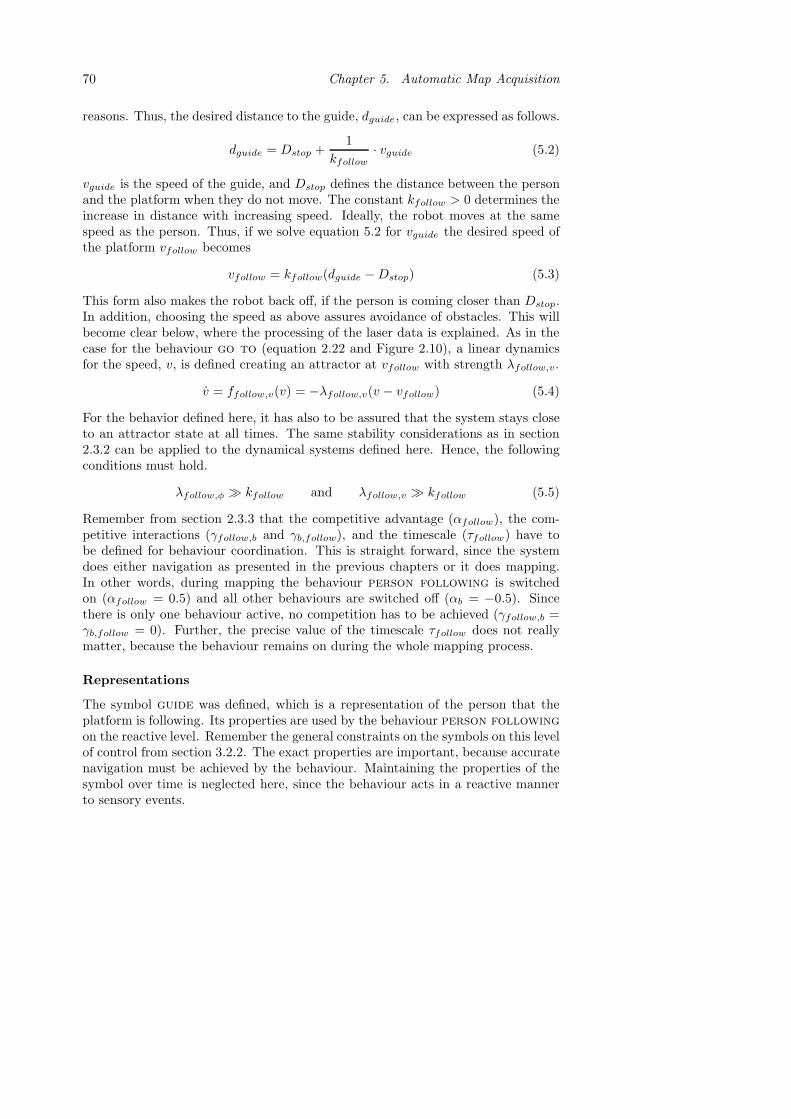
70 Chapter 5. Automatic Map Acquisition
reasons. Thus, the desired distance to the guide, dguide, can be expressed as follows.
dguide = Dstop +1
kfollow· vguide (5.2)
vguide is the speed of the guide, and Dstop defines the distance between the personand the platform when they do not move. The constant kfollow > 0 determines theincrease in distance with increasing speed. Ideally, the robot moves at the samespeed as the person. Thus, if we solve equation 5.2 for vguide the desired speed ofthe platform vfollow becomes
vfollow = kfollow(dguide −Dstop) (5.3)
This form also makes the robot back off, if the person is coming closer than Dstop.In addition, choosing the speed as above assures avoidance of obstacles. This willbecome clear below, where the processing of the laser data is explained. As in thecase for the behaviour go to (equation 2.22 and Figure 2.10), a linear dynamicsfor the speed, v, is defined creating an attractor at vfollow with strength λfollow,v.
v = ffollow,v(v) = −λfollow,v(v − vfollow) (5.4)
For the behavior defined here, it has also to be assured that the system stays closeto an attractor state at all times. The same stability considerations as in section2.3.2 can be applied to the dynamical systems defined here. Hence, the followingconditions must hold.
λfollow,φ � kfollow and λfollow,v � kfollow (5.5)
Remember from section 2.3.3 that the competitive advantage (αfollow), the com-petitive interactions (γfollow,b and γb,follow), and the timescale (τfollow) have tobe defined for behaviour coordination. This is straight forward, since the systemdoes either navigation as presented in the previous chapters or it does mapping.In other words, during mapping the behaviour person following is switchedon (αfollow = 0.5) and all other behaviours are switched off (αb = −0.5). Sincethere is only one behaviour active, no competition has to be achieved (γfollow,b =γb,follow = 0). Further, the precise value of the timescale τfollow does not reallymatter, because the behaviour remains on during the whole mapping process.
Representations
The symbol guide was defined, which is a representation of the person that theplatform is following. Its properties are used by the behaviour person followingon the reactive level. Remember the general constraints on the symbols on this levelof control from section 3.2.2. The exact properties are important, because accuratenavigation must be achieved by the behaviour. Maintaining the properties of thesymbol over time is neglected here, since the behaviour acts in a reactive mannerto sensory events.

5.2. Implementation 71
Guide is extracted from sensor readings provided by the laser scanner. Theechos lying in the frontal 90◦ of the robot are considered. In general, the shortestone of these readings comes from the person that the robot is following. However,when passing narrow passages such as doorways, the obstacles on the side might becloser to the platform than the person. Also in empty corridors, when the distanceto this person is increasing (due to a higher speed), the corridor walls are closer tothe robot. To account for this, the sensor reading representing the person to followhas been determined as the one minimising the following expression.
di · (1 + | sin(ψi)|) (5.6)
di is the distance returned of laser beam i, and ψi is the direction of this beamrelative to the robot’s orientation. In this way, distances are weighted with theirdeviation from the robot’s orientation. Of course, this is a very crude approachto detecting a person. Nevertheless, it turned out to serve its purpose very well.Furthermore, it also facilitates obstacle avoidance by the person following be-haviour. If an obstruction is, for some reason, very close to the platform, the systemis backing off in a way defined in equation 5.4. After the laser beam representingthe person is determined, its direction parameterises the dynamics of heading di-rection ffollow,φ (equation 5.1). The returned distance of this beam is used by thedynamics of speed ffollow,v (equation 5.4).
The symbols corridor and obstacle are used for the map acquisition process(see next section). They are extracted in the same way as described in section3.3.1 with one exception. The frontal five sonar sensors (covering 90◦) are ignored,because they, usually, return readings from the guide. Note that the echos from thelaser scanner are only used for following a person. The only sensory data supportingthe whole map acquisition process are from the sonars.
5.2.2 Acquisition of the Map
Before presenting the actual acquisition method, the important properties of themap are quickly reviewed. Remember from section 3.1.2 that the nodes of thetopological map have an x- and a y-coordinate in a world-fixed coordinate system.The edges can be of three different types: “corridor”, “room”, or “door”. Thus,nodes have to be placed at every position of the environment where the edge typewould change, which means in front of every door. Further, places where the graphsplits up (for example corridor crossings) have to be represented by a node. Inaddition, all the places in the environment that are important for the specific taskscarried out (charging station and goal points) need to be reflected in the map by anode. In order to underline the working of the method presented here for large-scaleareas, the environment has been extended to the corridors outside our institute.Figure 5.2 depicts the topological map of this setting (about 60×70 meters). Thismap has been acquired manually by measuring actual distances between nodes. Thex- and y-coordinates of these nodes have been determined, precisely as illustrated

72 Chapter 5. Automatic Map Acquisition
in Figure 3.2. In other words, nodes are centered in corridors and an edge of type“door” goes through the middle of the door posts. The map shows all parts of thepremises that are actually accessible by the robot, which means no rooms with highthresholds at the doorway. Depending on the tasks, an arbitrary amount of nodescan be added to the map to include, for example, a mail slot where something hasto be picked up, office desks where it has to be delivered to, or any other points ofinterest.
−10 0 10 20 30 40 50
−10
0
10
20
30
40
Figure 5.2. The topological map of our institute. The circles depict nodes with aposition in a fixed coordinate system (units on the axes are in meters). Edges areof three different types: corridor (dashed lines), room (dotted lines), and door (solidlines). The charging station is depicted by the node at the origin. Goal points andother locations of importance for the navigational task can be added arbitrarily inthe rooms and the corridors.
The map is acquired in that a person is showing the robot around. The plat-form autonomously follows the guide through the environment (Figure 5.1). Thisperson carries a laptop to interact with the robot through wireless ethernet. Viathis interface, the system is updated about topological changes during their tour.The guide informs the program every time when they leave a room or a corridor,and then again, when a new room or corridor is entered. Also corridor crossingsand other points of interest (for example goal points) are messaged to the system.During such a trial the robot has an estimate of its position and orientation usingsimilar principles as during navigation (see section 3.3.2).
The map acquisition is happening online and begins at the starting location.First, the system places a node at its initial position. The meaning of the first edge(“corridor”, “room”, or “door”) is entered by the guide. The robot keeps track of its

5.2. Implementation 73
position and orientation through the odometric data. When the system is informedabout a new node (for example when leaving a room), the robot’s position coincidesprobably not exactly with the nodes correct position as introduced in Figure 3.2.Hence, corridors and doorways extracted from the sonar data are used to positionthe nodes. This is illustrated in Figure 5.3, where a possible trajectory of theplatform is shown (compare to Figure 3.2).
��������������������������������������������������������������������������������������������������������������������������������������������������������������������������������������������������������������������������������������������
��������������������������������
������������������������������������������������������������������������
����������������������������������������������������������������������������������������������������������������������������������������������������������������������������������������
������������������������������������������������������������������
������������������������������������������������������������������
����������������������������������������
����������������������������������������
������������������������������������������������
������������������������������������������������
����������������������������������������
����������������������������������������
��������������������������������
d d11
d2
d2
A
B
DC
Figure 5.3. Correct placement of nodes during the map acquisition process. Theblack line shows a possible robot trajectory. Nodes are depicted by circles. SituationsA-D are explained in the text.
A: The system is informed about leaving the room. While passing the door thenarrowest passage (doorway) is extracted from the sonar data. Its positionand the orientation of the door posts are saved.
B: The system is informed about having entered a corridor. The narrowest pas-sage since A is remembered and the upper node can be placed on the centerlineof the door. The robot continues following the guide along the corridor.
C: The corridor properties (orientation and distance to the walls) are extractedfrom the sonar data (see section 3.3.1).
D: The corridor properties are extracted again and averaged with the first guess.This gives a good enough estimate of the actual corridor. Thus the secondnode can be placed, centred in the corridor and aligned with the first node.Now the direction of the corridor is fixed. Hence, while the trial continues therobot’s position can be updated each time the Hough transform is invoked,as described in section 3.3.2.

74 Chapter 5. Automatic Map Acquisition
This whole process happens each time the platform moves from a room to a corridorand, similarly, the other way round. Further, nodes of goal points are placed at thelocation of the robot’s position estimate at the time the system is informed aboutplacing a node. Each time the guide tells the robot about a new node, it also entersthe type of the next edge via the terminal interface.
5.3 Results
Figures 5.4 and 5.5 show two topological maps acquired by the system. Theseare the result of two particular trials. All experiments result in their own maps,which do not look exactly the same. This is, in general, due to odometry drift,disturbances at door thresholds, and unprecise corridor estimates. However, theirdifference is in the same order as the discrepancy between the two examples pre-sented here. Hence, we focus the discussion on comparing these two with thecorrectly measured map in Figure 5.2. In general, experiments have shown that themaps acquired by the robot serve equally well for navigating between two arbitrarynodes as the precise one built by hand.
−10 0 10 20 30 40 50
−10
0
10
20
30
40
Figure 5.4. A map of our institute acquired by the robot (units are in meters):The circles depict nodes. Edges are of three different types: corridor (dashed lines),room (dotted lines), and door (solid lines). The docking station is depicted by thenode at the origin.
The most obvious difference between the two maps is that the angles betweenedges are not the same. This is particularly well visible at the long corridors.

5.3. Results 75
−10 0 10 20 30 40 50−20
−10
0
10
20
30
Figure 5.5. A map of our institute acquired by the robot (units are in meters):The circles depict nodes. Edges are of three different types: corridor (dashed lines),room (dotted lines), and door (solid lines). The docking station is depicted by thenode at the origin.
However, this does not matter, when the map is used later. Remember that thenavigational tasks are split up into subtasks that consist only of navigating fromone node to a neighbouring one. At the nodes themselves, task switches are invokedand the behaviours take care of the small scale structure of the environment. Forexample, when the robot has to enter a room from the corridor, the behaviour “doorpassing” guides the platform through the doorway, where the robot’s orientationrelative to the map is corrected again. Hence, the tasks do not fail as long ascorridors and doors can not be mixed up. However, this would only occur whenangular errors were in the order of 45◦.
Another discrepancy between the maps is the length of the door edges. This ishard to see in the figures, but they actually vary up to 1 meter. These differences,however, are not errors, since door nodes in rooms can be placed anywhere onthe centerline of the door (see section 3.1.2). This placement does not affect theexecutions of the navigational tasks.
One aspect of the map that is crucial for the navigation system to succeed isthe length of the corridor edges, in order to find the correct door. Comparing thesevalues of the acquired maps with the correct one suggests that the relative erroris in the order of at most 0.5%. Remember from the evaluation of the navigationsystem that the error of the position estimate during navigation is in the sameorder (section 4.3.2). It can be assumed that the system is able to find the correct

76 Chapter 5. Automatic Map Acquisition
door, if its position relative to the map is less than 1 meter. This suggests that theapproach presented here could successfully handle corridors up to a length of 100meters.
Another aspect that the navigation system has to rely on is the length of theedges inside rooms and the angles between them. The errors in length are equallysmall as in corridors. However, the errors in angle can be of the same magnitudeas between individual corridors, because no features of rooms are used to updatethe estimates of the robot’s orientation. This could lead to problems in two cases:1) if the rooms are very large, and 2) if the robot navigates inside the same roomfor a long time. Experiments show that rooms of the size of our offices do notpose any problems for navigation to a few goal points. Furthermore, if a taskdemands frequent navigation between nodes in the same room (for example, repet-itive fetch-and-carry between two tables), additional means to update the robot’sorientation are, probably, provided (for example extracting the tables from sen-sory data). However, additional studies would need to be carried out to verify thisbelieve.
The above mentioned simplification, of generally not using any features in therooms, provides an advantage in modelling the whole environment. Since no as-sumptions on the structure of a room are made, everything that does not look likea corridor or a doorway can be modelled as a room. However, this does not meanthat cluttered corridors need to be defined as rooms. Figure 5.6 shows an exam-ple of such a corridor that did not pose any problems to the behaviour corridorfollowing to safely navigate. Neither was it a problem to successfully update therobot’s orientation estimate in both navigation and map construction.
Figure 5.6. A cluttered corridor in our institute. These types of obstructions donot pose any problems for extracting the corridor features during navigation andmap building.

5.4. Discussion 77
5.4 Discussion
A rather simple mechanism for map construction was presented. A new behaviourperson following has been defined, which enables a robot to follow a personthrough an environment and simultaneously building a map. Experiments haveshown that this map can successfully be applied to navigate through our wholeinstitute. All the mechanisms have been integrated into one complete navigationsystem for large-scale domestic environments.
To emphasize the simplicity and robustness of the approach, the same featureextraction mechanisms as for navigation (section 3.3.1) have been used, which relyonly on data provided by sonar sensors. Further, the whole environment is modelledas a set of corridors, rooms, and doorways. This simplification allows to acquirea representation of the entire environment with rather basic mechanisms and lowCPU consumption. The latter permits to build the map online without any post-processing. This is clearly an advantage to SLAM approaches deploying KalmanFilters and Bayesian theory together with a complex world model. Recent workshows that also these methods can be applied in real-time; see (Guivant and Nebot,2001) and (Thrun et al., 2000) for two excellent examples. However, in theseexamples sophisticated algorithms had to be developed to be able to restrain CPUand memory consumption. Here, it has been shown that a map that is only usedfor navigation can be acquired in a much easier fashion.
The person detection, used for following the guide through the environment, isa rather crude approach. Sometimes, the system looses track of the person, and theguide has to reposition itself in front of the platform in order to be detected again.The implementation of a more advanced tracking algorithm (for example, (Schulzet al., 2001)) would definitely improve this part of the system. In addition, theinteraction of the guiding person with the robot is not particularly user-friendly.The little information given by the guide (presence of a node and type of the edge)could as well be communicated via a speech interface. This enhancement wouldmake the system much easier to use.

78

Chapter 6
Human-Robot Interaction
The research presented in this chapter has been conducted during a four monthsstay at the Advanced Telecommunications Research Institute (ATR) in Kyoto,Japan. The Intelligent Robotics and Communication Laboratories at ATR focus onrobotics research in the context of human-robot interaction. Navigation of a mobileplatform interacting with people is driven by very different constraints than it is forfunctional tasks like driving from a point A to a point B. An introduction to thistype of research and the navigational constraints are given in section 6.1. Then, insection 6.2, the robotic platform and the interaction scenario tested in these studiesare presented. In addition, some results from psychology are considered, whichpose constraints on the robotic system for the interaction task. The design andimplementation of the actual system is described in section 6.3 and experimentalresults are presented in section 6.4. Finally, a summary and a discussion of avenuesof future research are provided in section 6.5.
6.1 Introduction
In service robotics, which is the research context for the other chapters of thisthesis, human-robot interaction is primarily for task specification. Subsequently,the mission the robot has to fulfill is defined. Hence, its behaviour is task driven.This is the main difference to the research approach that is pursued at ATR, whichis probably best described by personal robotics (Ishiguro et al., 2003). The goal isto develop a socially interactive robot (Fong et al., 2003) that “lives” in people’shomes and coexists with humans in their daily live. Hence, the behaviour of therobot is very much interaction driven. The actions of the robot are dependent onthe presence of humans and on their willingness to interact. Further, the type anddegree of interaction determines the subsequent behaviour. Also outcomes of aprevious encounter can influence this interplay. For example, when a robot greetssomebody, the response of this person determines the subsequent actions: shaking
79

80 Chapter 6. Human-Robot Interaction
hands, engaging in a conversation, following the person to another room, and soforth. If this particular person is met again later, the interaction might be basedon the first meeting. For example, the same questions should not be asked again.
For all these types of tasks, navigation of the platform is a basic problem thathas to be attacked. However, the constraints on the navigational tasks are in someways very different than for a fetch-and-carry type mission. Following the generalstructure of this thesis, some considerations are outlined below in the contexts ofcontrol and representations.
The major issue concerning the control is that the robot’s behaviour has to look“natural”. The movements have to be smooth and “human-like”, since a personalrobot is supposed to live, communicate and interact with people sharing the sameenvironment. The quality of its movements influences strongly the perceived intel-ligence of the robotic system. As opposed to a delivery robot, which has to reach acertain destination with few constraints on the motion pattern. There, the only re-quirements are that the platform gets to the goal safely and in reasonable time. Webelieve that the dynamical systems approach is especially well suited for navigationin the context of human-robot interaction. Through its smooth switching betweensubtasks a continuous control signal can be assured at all times. Further, the speedof the platform is an important factor influencing humans’ reactions to the robot’smovements. In this thesis, it has been shown how the dynamical systems approachcan be extended to the control of speed; unlike other approaches, which often onlyincorporate heading direction and control the speed by some external module.
The representations of the environment for human-robot interaction are differ-ent than the ones for navigating from A to B in two ways. On the one hand, thedetection of geometrical features for local navigation are more complex. For ex-ample, the system has to be able to distinguish between humans and other objectslike tables and chairs. In the earlier chapters of this thesis they were both con-sidered as obstacles. On the other hand, the context information, which enablesbehaviour switching, is of a different nature. In delivery missions, it has mainly theform of locations in the environment as described in section 3.3.2. Here, detectedevents, which define the state of interaction including its history, determine whichbehaviour to activate next. These differences in representations require, typically,more complex sensing abilities. In addition, a richer world model than a map of theenvironment is needed. For this purpose, the topological map introduced in section3.1.2 has been extended to a state map, which incorporates both geometrical loca-tions and interaction events. Further, the framework for anchoring proposed in thisthesis (section 3.2.2) is applied here as well. The symbols can still be separated forthe two levels of control, although their properties are somewhat different.
This chapter presents some initial studies and experiments on robot navigationexplicitly for human-robot interaction. The emphasis lies not on the complexityof the task as such. Rather on verifying of the following points: 1) Is the dynam-ical systems approach suited for navigation in interaction tasks? 2) How can thetopological map be combined with interaction relevant information? 3) Does theframework for anchoring proposed in this thesis still hold?

6.2. The Experimental Setup 81
6.2 The Experimental Setup
An experimental setup has been defined in order to show the applicability of themethods developed in this thesis to navigation for human-robot interaction tasks.First, in section 6.2.1, the robotic platform Robovie is described. An actual sce-nario, relevant for a robot sharing an environment with humans, is described insection 6.2.2. In such a scenario, task constraints are usually given by psycholog-ical studies on human behaviour. These considerations are presented in section6.2.3. Finally, the actual implementation is presented later in section 6.3.
6.2.1 The Platform
The platform used in these studies is a humanoid system on wheels called Robovie(see Figure 6.1). The robot has a height of 120 cm and its weight is about 40kg. The system is built on a Pioneer platform of 45 cm diameter with a twowheel differential drive. The robot has two arms with 4 degrees of freedom each.The head can be rotated around all three axis. Mounted on the head are twocameras that have also 2 degrees of freedom. There are various sensors mountedon the platform. The base has 16 ultrasonic sensors and encoders on the wheel forodometric information. Another 8 sonars are mounted on the upper body. Further,the robot is equipped with 3 IR motion sensors on its shoulders, the two camerason the head, and an omnidirectional camera on a sort of antenna. A number oftouch sensors are distributed all over the body. In addition, two microphones anda loudspeaker provide a speech interface. The whole system is controlled by anon-board computer with a Pentium III processor running Linux.
Robovie has been used in various studies on human-robot interaction (Ishiguroet al., 2003). The system has modules for detecting moving objects and trackingfaces. It is able to perform a number of gestures like greeting, waving, pointing, orhugging. Through moving its head it can give a realistic impression of attention.The speech interface allows some basic communication.
6.2.2 The Scenario
A robot sharing its environment with humans as an equal being has to be able toengage in conversations. In order to do so, the system needs several abilities, whichcan be tested with the following scenario:
1. The robot enters a room and looks around for people.
2. If any humans are present, the platform approaches them.
3. The robot stands next to the person(s) and initiates or joins a discussion.
4. When the discussion is over or the robot is asked to do something else, itleaves the person(s) towards the exit of the room.

82 Chapter 6. Human-Robot Interaction
Figure 6.1. The robotic system Robovie.
5. The system resumes some old plan, responds to some new request, or wandersaround in its environment.
Note that the emphasis of these studies is navigation. In the actual experiments(see section 6.4) the robot is in fact not really communicating. Keeping up a con-versation over a reasonable time is very hard and a research field in itself. In otherwords, the platform is joining the group of people as a passive listener. This sce-nario is a minimal approach to demonstrate navigation in human-robot interactionincluding the following important issues:
• Detecting the presence of people.
• Moving in an appropriate fashion in relation to humans.
• Sequencing of different subtasks.
• Keeping track of position and plan execution.
Before the actual implementation of this scenario is presented, some issues on nav-igation in relation to humans are considered below.

6.3. Implementation 83
6.2.3 Psychological Considerations
The design of autonomous systems for human-robot interaction is highly influencedby psychological studies. There exists a great amount of results from this areadescribing the way how humans interact with each other. It is the aim for a personalrobot to follow the same principles when acting in a human environment. Thisenables the acceptance of a robotic platform as an equal being on the one hand.On the other hand, it increases the perceived intelligence of the system (Kanda,Ishiguro, Imai, Ono and Mase, 2002). Further, psychological methods in the formof questioning human subjects about their impression of a robot, are a valuablemethod to evaluate and measure the quality of an interacting system (Kanda et al.,2001; Kanda, Ishiguro, Ono, Imai and Nakatsu, 2002).
This chapter deals with the navigation aspects of an interaction task. Hence,studies about people’s overall movements and their position relative to each otherare taken into account. Kendon (1990) presents results on extensive studies on thistopic. The main points being that certain formations among people are maintained,while they are interacting. Although individual people often are moving due todifferent reasons, the other persons are compensating for this by also moving inorder to maintain the formation. In a group conversation, this formation usuallyhas the form of a ring, where all persons keep equal distance to their neighbours.When only two people are engaged in a discussion, they keep a constant distancebetween themselves. Of course, there are many variations and exceptions of thesegeneral rules depending on the relation among the persons and the state of theconversation. However, the main principle described above is rather dominant andwill define the constraints for the design of the control system.
6.3 Implementation
The implementation of the scenario described above is described in this section.Following the general structure of this thesis, the issues on control and representa-tions are discussed separately.
6.3.1 Control
The control scheme is designed in the framework of the dynamical systems ap-proach introduced in section 2.2. To provide the functionality of joining a group ofpeople and engaging in a conversation (as outlined in section 6.2.2) two additionalbehaviours were defined.
• approach human: driving towards a person or group of persons after theyhave been detected. When getting close to the people the platform shouldslow down in a smooth manner.
• keep distance: positioning the robot, such that it is part of a ring formationwith the other persons. In other words it has to face the centre of the group,

84 Chapter 6. Human-Robot Interaction
while keeping a constant distance to its neighbours. Alternatively, if onlyone human is present, the platform should face this person and maintain aconstant distance.
These behaviours are integrated into the existing control system presented in sec-tion 2.3. This design in one framework allows switching between fetch-and-carrytype navigation and interaction type navigation at all times. Hence, the same be-havioural variables are chosen (equation 2.7): the heading direction φ and the speedv. Also here the dynamics of the two variables will not depend on each other. Thus,the notation defined in equation 2.8 will be used.
Dynamics of Heading Direction
The behaviour approach human is supposed to align the robot’s heading directionwith the direction ψhuman of the detected person. This is, basically, the sameconstraint as for the behaviour go to. Thus the same functional form as in equation2.9 (Figure 2.2) is used. The constant λhuman,φ > 0 defines the strength of theattractor at ψhuman.
φ = fhuman,φ(φ) = −λhuman,φ sin(φ − ψhuman) (6.1)
In the case of one person j present the behaviour keep distance has to turn therobot towards it. This can be achieved by creating an attractor at ψj , the directionof this person.
fj,φ(φ) = −λdist,φ(φ− ψj) e−cdist1(dj−Dinter) (6.2)
dj is the distance to the person, Dinter defines the desired interacting distancebetween this person and the platform, the constant cdist1 > 0 is a decay constant,and λdist,φ determines the strength of the attractor. In case of multiple persons,the resulting dynamics is computed by adding the individual contributions.
φ = fdist,φ(φ) =∑
j
fj,φ(φ) (6.3)
Comparing equation 6.2 to the usual attractor dynamics used in this thesis (forexample 6.1) shows two main differences: a linear function instead of a sine anda distance decay term. The reason for the linear function is averaging. In otherwords, if several people are surrounding the robot at equal distance, the dynamicsof equation 6.3 creates an attractor at the average direction. This ensures thatthe robot faces the centre of a formation as described in section 6.2.3. However,since this function is not 2π-periodic, the angles have to be defined in such away that |φ − ψj | ≤ π. The distance dependent decay term has the purpose of“repairing” a formation. If one person in the group steps closer to the robot (dj <Dinter), its contribution becomes stronger than the others as shown in Figure 6.2.This ensures that the platform is turning towards this person, while backing off.Subsequently, when the distance increases again, it is aligning itself with the centerof the formation.

6.3. Implementation 85
2ψ1ψ0
φ
φ
Figure 6.2. The dynamics of heading direction φ for keep distance in the caseof two persons present (dashed curves). If person 2 steps closer to the robot, itscontribution becomes stronger. Thus, the overall dynamics (solid curve) has anattractor close to the direction of that person.
Dynamics of Speed
The desired speed for approach human is dependent on the distance dhuman tothe people that have to be approached. In the same way as when a human isapproaching a group of people, the platform should slow down when getting closer.Further, the speed ought to be bounded by some maximum value vhuman,max inorder not to scare anybody. Hence, the desired speed vhuman is defined as follows
vhuman = min(khumandhuman, vhuman,max) (6.4)
where khuman > 0 is a constant. As in the case for the behaviour go to (equation2.22 and Figure 2.10), a linear dynamics is defined creating an attractor at vhuman
with strength λhuman,v.
v = fhuman,v(v) = −λhuman,v(v − vhuman) (6.5)
In the case of interacting with a single person, the behaviour keep distancehas to make the platform back off when the person gets closer than the desiredinteraction distance Dinter . If the distance, however, becomes greater the robotshould approach. In order to avoid abrupt changes in movement, these speeds arealso regulated by the distance dj to that person. Thus the desired speed can beexpressed in the following form.
vj = kdist(dj −Dinter) (6.6)
with a constant kdist > 0. Also for this behaviour the function f is chosen linear.
fj,v(v) = −λdist,v(v − vj) e−cdist2(dj−Dinter) (6.7)

86 Chapter 6. Human-Robot Interaction
λdist,v determines the strength of the attractor and cdist2 is a decay constant. Theoverall dynamics of speed for keep distance is the sum of the contributions foreach individual person.
v = fdist,v(v) =∑
j
fj,v(v) (6.8)
The distance dependent term in equation 6.7 weighs the attractors of contribu-tions from closeby people stronger than the ones from people further away. Thisalways ensures that the platform is avoiding persons that are standing too close(Figure 6.3). For more details and illustration on the behaviour emerging fromthese dynamics see the results in section 6.4.
1v
2v0
v
v
Figure 6.3. The dynamics of speed v for keep distance in the case of two personspresent (dashed curves). Person 1 is too close to the robot, while person 2 is too faraway. Since the attractor of the closer person (v1) is stronger, the overall dynamics(solid curve) makes the platform drive backwards.
For the behaviors defined here, it has also to be assured that the system staysclose to an attractor state at all times. The same stability considerations as insection 2.3.2 can be applied to the dynamical systems defined here. Hence, thefollowing conditions must hold.
λhuman,φ � khuman and λhuman,v � khuman (6.9)λdist,φ � kdist and λdist,v � kdist (6.10)
Behaviour Coordination
The two new behaviours presented above are integrated into the existing system ofthe five behaviours defined in section 2.3. Thus, the overall dynamics of the system

6.3. Implementation 87
is obtained from the weighted summation of all behaviours according to equation2.4: (
φ
v
)=
∑b∈B
|wb|(fb,φ(φ)fb,v(v)
)+ noise (6.11)
with B = {goto, obst, corr, wall, door, human, dist}. For the coordination of thebehaviours, the competitive advantages αb, the competitive interactions γb′,b, andthe time constants τb in the competitive dynamics of the weights wb (equation 2.5)have to be chosen appropriately. Here, these choices are rather straight forward.Only sequencing of the subtasks has to be achieved. First, entering the room, then,approaching the group of people and keeping the formations, and finally, leavingthe room again.
The competitive advantages αb express the applicability of a behaviour b in thecurrent context. Until the robot has entered the room, navigation is working in thesame way as described earlier in this thesis. In other words, αhuman = αdist = −0.5.All other competitive advantages are set to exactly the same values as defined insection 2.3.3. Then, as soon as the humans in the room are detected, the competitiveadvantage for approach human, αhuman, is set to 0.5 and all other behavioursare switched off (αb = −0.5). When this subtask is completed, which means thegroup of persons are reached, keep distance is switched on by setting αdist = 0.5.Further, everything else is turned off (αb = −0.5). Finally, as the interaction iscompleted, αhuman is set to -0.5 again. Now, the activity of all other behaviours is,again, determined by the navigation scheme as defined in 2.3.3. Hence, the robotis able to return to the door and fulfill some arbitrary navigation mission.
The competitive interactions γb′,b allow an active behaviour b′ to suppress theactivity of another behaviour b. The simple sequencing of subtasks required here,does not introduce any conflicts among behaviours. This means that all new com-petitive interactions (γhuman,b, γdist,b, γb′,human and γb′,dist) are set to 0. All otherγb′,b are, of course, set to the exact same values as in section 2.3.3.
Finally, the time constants τb determine the rate at which behaviours are turnedon and off. Because, here, the behaviours are active one after the other, these valuesare of minor importance. The only constraint being, that they should not be toohigh (τhuman = τdist τobst), such that behaviour switches do not occur tooabruptly. This ensures smooth control of the platform, which leads to “naturally”looking movements.
6.3.2 Representations
Geometrical representations are used to facilitate the interaction tasks. Basically,properties of the detected humans parameterise the behaviours introduced above.Further, context information is needed to allow switching between the individualnavigation strategies. The symbols that represent these properties to allow decisionmaking are introduced below. Following the framework proposed in section 3.2.2they are, also here, treated separately for the two levels of abstraction.

88 Chapter 6. Human-Robot Interaction
The Reactive Level
Remember the general constraints on the symbols on this level of control from sec-tion 3.2.2. The exact properties are important here, because accurate navigationhas to be assured by the behaviours. The platform has to be able to approachhumans and maintain formations with them. Further, collisions have to be avoidedwhile doing this. Maintaining the properties of the symbols over time is not impor-tant here, since the behaviours act in a reactive manner to sensory events.
The behaviour approach human makes use of the symbol human. After therobot has entered the room, a person tracking module is initiated. This modulelooks for a person using a combination of data from different sensors: the omni-directional camera, one of the cameras on the robot’s head, the sonar sensors andinfrared sensors mounted on the shoulders of the robot. The output of this modulespecifies the direction ψhuman of the human. This value serves as a parameter forfhuman,φ (equation 6.1). With help of the sonar sensors the distance dhuman to thisperson can be determined. This influences fhuman,v (equations 6.4 and 6.5), thedynamics of speed for the behaviour approach human.
The behaviour keep distance uses of the properties of the symbol person.The persons surrounding the robot, while interacting are extracted from the sonardata. This is done in a very similar fashion as for obstacles (section 3.3.1). The 30most recent sonar readings are considered. Persons are reconstructed from thesedetected echos in ascending order of their distance to the robot. The echo closestto the robot defines the first person whose orientation in the robot frame is givenby the axis of the sensor that received the echo. A new person is recorded forevery subsequent echo whose orientation differs by an angle of at least 45◦ fromany previously identified person. New persons are added in an incremental fashionuntil the sonar buffer contains no further echos. For each person j, the dynamicsof heading direction fj,φ (equation 6.2) uses the angle ψj and the distance dj asparameters. Further, also the dynamics of speed fj,v (equation 6.7) is dependenton the distance to the person.
The Deliberative Level
On the deliberative level, decisions about which subtasks to initiate have to bemade. In order to do this the system has to be able to keep track of the overallmission by using some kind of world model. For the tasks of moving from a pointA to a point B, this world model is in the form of the topological map introducedin section 3.1.2. The nodes in this map correspond to locations in the environment,where a change in the navigational strategy has to occur. In interaction tasks,behaviour selection is not only governed by locations, but also by events in thecurrent interaction of the robot with the humans. In other words, the world modelhas to be extended in such a way, that it can represent these events.
A state diagram has been defined preserving the graph structure of the topolog-ical map. Figure 6.4 shows this diagram for the scenario described in section 6.2.2.
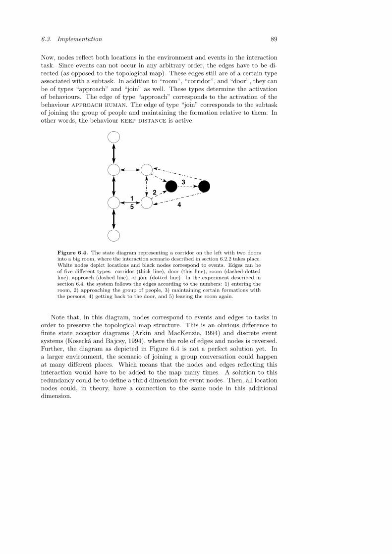
6.3. Implementation 89
Now, nodes reflect both locations in the environment and events in the interactiontask. Since events can not occur in any arbitrary order, the edges have to be di-rected (as opposed to the topological map). These edges still are of a certain typeassociated with a subtask. In addition to “room”, “corridor”, and “door”, they canbe of types “approach” and “join” as well. These types determine the activationof behaviours. The edge of type “approach” corresponds to the activation of thebehaviour approach human. The edge of type “join” corresponds to the subtaskof joining the group of people and maintaining the formation relative to them. Inother words, the behaviour keep distance is active.
2
3
5 41
Figure 6.4. The state diagram representing a corridor on the left with two doorsinto a big room, where the interaction scenario described in section 6.2.2 takes place.White nodes depict locations and black nodes correspond to events. Edges can beof five different types: corridor (thick line), door (this line), room (dashed-dottedline), approach (dashed line), or join (dotted line). In the experiment described insection 6.4, the system follows the edges according to the numbers: 1) entering theroom, 2) approaching the group of people, 3) maintaining certain formations withthe persons, 4) getting back to the door, and 5) leaving the room again.
Note that, in this diagram, nodes correspond to events and edges to tasks inorder to preserve the topological map structure. This is an obvious difference tofinite state acceptor diagrams (Arkin and MacKenzie, 1994) and discrete eventsystems (Kosecka and Bajcsy, 1994), where the role of edges and nodes is reversed.Further, the diagram as depicted in Figure 6.4 is not a perfect solution yet. Ina larger environment, the scenario of joining a group conversation could happenat many different places. Which means that the nodes and edges reflecting thisinteraction would have to be added to the map many times. A solution to thisredundancy could be to define a third dimension for event nodes. Then, all locationnodes could, in theory, have a connection to the same node in this additionaldimension.

90 Chapter 6. Human-Robot Interaction
Remember from section 3.3.2, that the symbol topological context has aproperty “location” which is used by the behaviour coordination system to activatethe appropriate set of behaviours (section 2.3.3). The value of “location” is definedby the edge of the map that the platform is currently following. Also for the statediagram, the system has to keep track of the current edge. In order to do this,the abstract symbol sensory context, introduced in section 3.3.2, provides threemore properties: “human detected”, “person approached”, and “interaction over”.All of them having values of either true of false. “Human detected” is determinedby the person detection module mentioned above. It’s value defines αhuman and, iftrue, initiates the behaviour approach human. The value of “person approached”is determined by dhuman the distance to the group of people. If this value is belowa certain threshold “person approached” becomes true, which influences αdist andthe behaviour keep distance is activated. In the present implementation, theend of the interaction is defined by a timeout after 2 minutes. However, it couldeasily be determined by some event of the interaction (for example speech or acertain gesture). This sets “interaction over” to true, which in turn switches off theinteraction behaviours (αhuman = αdist = −0.5). The robot will switch back to purenavigation mode (see section 2.3) and continue its way through the environmentaccording to its old plan.
Further the symbol pose reflecting the robot’s position and orientation is con-stantly updated as described in section 3.3.2. When the interaction is over, thisinformation is needed by the system in order to proceed to the next node in themap and continue its way through the area.
6.4 Results
The scenario described in section 6.2.2 has been tested. The robot entered a room,detected a group of three humans engaged in a conversation, and joined this group.While talking to each other, the persons were moving slightly. Further, one of thesepersons was leaving the group at some point. Later, this person was coming backand joining the group again. During all these movements of the people, the robothad to adjust its own position to remain in a formation as described in section 6.2.3.Further, the robot turned its head towards the person closest to it in order to give animpression of listening to the conversation. Finally, the robot was leaving the groupand heading for the door where it entered the room in the first place. Robovie wasnot engaged in the conversation and acted as a passive listener. Therefore, leavingthe group is not triggered by the end of the conversation. The robot simply returnsto its old task after 2 minutes of listening. The path through the state diagram forthis task can be seen in Figure 6.4.
The three subjects used for the experiment have never seen the robot before.This was an important condition, because they must not know about the plat-form’s moving patterns and automatically adjust to it. The main constraints onthe navigation are that the robot moves naturally in a similar way as humans do.

6.4. Results 91
The subjects where questioned about their impressions after the experiment. Theyjudged the moving patterns of the robot as natural and had the impression thatRobovie was listening to their conversation.
A video has been taken of the experiment. However, these kind of resultsare very difficult to present on paper. An attempt to give an impression of theexperiment is done by displaying trajectories. The room where the interaction tookplace is equipped with a system for tracking optical beacons with a large numberof cameras. Such beacons were placed on the subjects and the robot in order totrack their position during the experiment. The movements of the robot and thesubjects during a conversation with a constant amount of people are really smalland hard to draw and interpret. However, during major events, for example whena person is leaving, the robot has to move bigger distances to remain in formationwith the humans. The trajectories during some of these major events are displayedand discussed below.
Figures 6.5 to 6.8 show the trajectories of the robot (dashed line) and thesubjects (solid lines) for four short sequences during the interaction task. Theunits are measured in meters. The circles indicate the approximate size of therobot and the persons. The dashed circles indicate the position at the beginningof the sequence. The solid ones show the final positions when the pictures on theright of the plots were taken.
Figure 6.5 shows the trajectories just after the robot has entered the door andis approaching the group of people. Before the robot got there the persons werearranged in a regular triangle (dashed circles). As soon as the robot came close, theyrearranged their positions to open up space for the platform. Robovie positioneditself such that the four have about equal distances to each other.
−2 −1 0 1
−1
0
1
2
Figure 6.5. The robot approaches the group of people.
In Figure 6.6 maintaining formation after a person was leaving can be observed.At the beginning of the sequence the four stood at about equal distances to eachother (dashed circles). Then, the person on the right hand side was leaving. The

92 Chapter 6. Human-Robot Interaction
other two and Robovie were moving in such way that the new formation constitutesa rather regular triangle (solid lines).
−1 0 1 2−1
0
1
Figure 6.6. The person on the right hand side is leaving the formation.
In Figure 6.7, it can be observed how the subjects were moving when the thirdperson joined the group again. At first, the two persons and the robot were atsimilar positions as at the end of the sequence of Figure 6.7. Then the thirdperson was approaching from the top left. Robovie and the person on the right areopening up space, such that the four of them constitute a similar formation as inthe beginning of the sequence of Figure 6.7.
−1 0 1
0
1
Figure 6.7. The third person is returning and approaching the group.
Figure 6.8 displays the end of the interaction task. The dashed circles show theindividuals in regular formation. Then after 2 minutes of interaction, the end ofthe task was triggered and the robot left the group in the direction from where itcame from.

6.5. Discussion 93
−1 0 1
0
1
Figure 6.8. The robot leaves the group of people.
6.5 Discussion
A basic scenario for testing navigation in human-robot interaction tasks has beendefined. Two new behaviours have been designed, which facilitate the system toapproach a group of people and to maintain a certain formation while interacting.Experiments showed that the robot is able to reposition itself when these formationschange due to different events. Further, the way the robot moves and finds itsposition in the group has been judged naturally by the test subjects.
Human-robot interaction poses different constraints on navigation than deliverymissions, which were the subject of the earlier chapters of this thesis. However, inthis chapter the following has been shown: 1) The dynamical systems approachis also suited for behaviour design in these types of tasks. 2) The world model(topological map) could easily be extended in order to contain information relevantfor interaction. 3) The anchoring processes could be organised in the same way asin the proposed framework. In essence, this shows that the methodologies used inthis thesis are not restricted to fetch-and-carry type mission. They can easily beextended to form the basis of more general navigation systems.
There are a number of other robotic systems that move around in spaces sharedwith humans and that engage in some form of interaction (see (Fong et al., 2003) fora survey). One type of systems that attract a great deal of attraction and operatein crowded spaces are museum tour guides. Rhino in the “Deutsche Museum Bonn”(Burgard et al., 1999), its successor Minerva in the “Smithsonian’s National Mu-seum of American History” in Washington (Thrun et al., 1999), and Robox at the“Swiss National Exhibition Expo02” (Siegwart et al., 2003) are the most popularexamples. All these systems possess the ability to interact with humans. However,this interaction is based on speech, gestures, and other visual cues. Navigationis not considered in the context of an interactive purpose. In Robox, people aretreated as dynamic obstacles only, which are fed to an obstacle avoidance module(Philippsen and Siegwart, 2003). In Rhino and Minerva, humans are detected by

94 Chapter 6. Human-Robot Interaction
cameras in order to initiate interaction tasks (Schulte et al., 1999). These tasksare restricted to the upper body of the robot and do not influence the navigationsystem.
Only recently, some research has been devoted to the role of navigation forsocially interactive robots. Simply turning towards persons of interest allows therobot to express some personality (Bruce et al., 2002; Okuno et al., 2003). Tan et al.(2003) made some first considerations of human-robot formations for cooperativemanipulation. Further, Nakauchi and Simmons (2000) discussed the personal spacesof humans similar to the psychological arguments in section 6.2.3. They consideredthese constraints when implementing a robot for standing in a line to get a coffee.The work presented in this chapter is another initial example of incorporatingnavigation into the interaction loop. We believe that this is necessary and will beseen in personal robotic systems in the future.
The design and results presented in this chapter are clearly some simplifiedinitial studies. Human formation are, in general, more complex than discussed here.For example, the distance to other people is dependent on the personal relationsamong them (Hall, 1966). Also the type of interactive means used (gestures orspeech) influence the formations among the participants. This information couldbe incorporated into a system by using modules for recognising individual humansand interpreting their gestures (Furukawa et al., 2003). This system would alsofacilitate to notice differences between humans and objects like chairs. This againwill lead to more advanced formation control than in the present implementation.

Chapter 7
Discussion
In the future, different indoor applications of autonomous robots are expected toopen up markets for the industry. Various tasks in domestic environments can beexecuted by mobile systems, such as vacuum cleaning, delivery missions, or helpfor elderly people. This thesis deals with several aspects of indoor navigation forsuch mobile platforms. These systems have to work successfully in any kind ofarea consisting of rooms and corridors. Hence, the emphasis in the work presentedhere is on minimalistic models that rely only on the very basic structures of suchenvironments. Thus, the system is designed in a general fashion without any de-tailed assumptions on the specific setting. Furthermore, no means of engineeringthe environment have been used. Such investments are believed to be too expensivefor the mass market.
The core of this thesis is the development of the indoor navigation system fordelivery type missions. Its design, the methods used, and the results are sum-marised and discussed in section 7.1. In section 7.2, the two extensions presentedare reviewed: automatic map acquisition and navigation in human-robot interac-tion. Finally, the thesis concludes in section 7.3 with a discussion of the majorissues that were not tackled in this work.
7.1 Indoor Navigation
The dynamical systems approach was the framework of choice for designing thenavigation system in a behaviour based fashion. This led to a hybrid deliberativearchitecture, as in most existing navigation approaches. This architecture definestwo levels of abstraction. On the one hand, the reactive level assures safe navigationbased on behaviours taking into account the local features of the environment. Onthe other hand, the deliberative part coordinates these behaviours using abstractcontext information and a predefined world model. Hence, this part is responsiblefor task switching and long-term mission planning.
95

96 Chapter 7. Discussion
For the control on the reactive level, five different behaviours have been designedmotivated by the general structure of a domestic environment: go to, obstacleavoidance, corridor following, wall avoidance, and door passing. Eachof these behaviours provides the robot with the ability to solve a navigationalsubtask. Their control laws are defined by a dynamical system. The individualtask constraints are expressed as fixpoints in the space of the two behaviouralvariables: the heading direction φ and the speed v. These fixpoints and otherparameters of the dynamical systems are specified by the geometrical properties ofobjects surrounding the robot. The perception of these objects is mainly governedby the type of sensors the platform is equipped with. Here, sonars provide the datafrom which abstract representations of the objects are extracted. This is done byfeature detectors for obstacles, corridors, doors, and walls. The precisionof the properties of these symbols is rather important, since the behaviours areresponsible for safe and accurate navigation. On the other hand, the problem ofmaintaining these properties over time can be neglected here. The behaviours arereactive modules that respond to immediate sensory events. At what time thefeature detectors have to be run and the symbols anchored is determined by thecontext information of the deliberative level.
The properties of the symbols parameterise the dynamical system of each be-haviour. This allows decision making processes on the reactive level. In the dy-namical systems approach, this decision making is expressed by bifurcations in thedynamics of the behavioural variables. This was illustrated in more detail by a sit-uation where the robot has to decide if a gap between two obstacles is wide enoughto pass between them or not. At such a bifurcation, the amount and nature offixpoints changes, which leads to a qualitatively different behaviour of the robot.Not only constraints on the individual behaviours, but also the conditions for theoccurance of such a bifurcation can be expressed precisely in the mathematicalformalism of this approach.
On the deliberative level, the activation of the different behaviours is coordinated.They are switched on and off on individual timescales through a competition frame-work defined by another dynamical system. Next to these timescales, the compet-itive dynamics is parameterised by so called competitive advantages and competi-tive interactions. They express the applicability of a behaviour and conflicts amongthem, dependent on the current situation. To express this information, abstractsymbols are defined: sensory context and topological context. The sen-sory context reflects detection of symbols on the reactive level, like open doorsand the presence of obstacles. Furthermore, the battery level is monitored to deter-mine when the platform has to get back to the charging station. The topologicalcontext keeps track of the the robot’s position within a topological map. Such amap has been defined constituting the world model of the system. It reflects thelarge scale structure of the environment consisting of rooms, corridors, and doors.This map facilitates task switching by recognising places in the environment us-ing the symbol pose, which is an estimate of the robot’s position and orientation.

7.1. Indoor Navigation 97
When anchoring the symbols on this level, emphasis is put on recognition of contextand maintenance of the pose over time. The exact properties are of minor impor-tance, since the execution of subtasks on the reactive level is deals with accuratenavigation. Switching between these subtasks is the form of decision making onthe deliberative level. Also here, this is expressed by bifurcations, this time in thecompetitive dynamics of the weights.
The navigation system has been tested on the premises of our institute, an envi-ronment of about 20×70 metres. For avoiding obstacles, passing between them,and avoiding walls, the performance predicted from the mathematical analysis inthe system design was displayed. Furthermore, the robot was able to accomplishmissions over long distances and to cope with unforeseen situations. The pose es-timate of the robot could be maintained throughout the trial. The accuracy ofthis estimate was sufficient to use the topological map successfully and perform theappropriate task switches. In addition, the same system with identical parametershas been used to successfully navigate a different platform in a different setting.This further underlines the generality of the design.
In this work, the dynamical systems approach has been applied for the first timeto realistic tasks in large-scale real-world environments. In addition, it has beenextended to the entire control of the platform via integrated speed control. Asopposed to most earlier approaches, where only the heading direction is controlledthrough this framework. Furthermore, the behaviour coordination scheme has beenexploited more thoroughly. It was shown that this scheme allows a rich variety ofcombinations of individual behaviours. In particular, both arbitration and fusioncan be achieved. The form of the topological map defined in this thesis, facilitatesthis coordination of sets of behaviours. By using this map to parameterise thecompetitive dynamics, it was demonstrated how continuous values of geometricalproperties and discrete information about the environment’s topology can be in-tegrated into the same framework. Moreover, the dynamics ensure a continuouscontrol signal at all times, since the behaviours are switched on and off on finitetimescales. In essence, the system presented shows that one can relax the need forcontinuous pose estimation while maintaining a possibility for smooth behaviourswitching. This continuous control signal can even be achieved for decision making,which is actually a discrete process, through the occurance of bifurcations in thedynamical systems.
All these representations, if continuous geometrical properties or discrete con-text information, must be anchored in the real-world. This problem, which is com-putationally very expensive in general, was considerably simplified in this work.The symbols used for the two levels of control need to have rather different proper-ties. Hence, their anchoring processes can be distinguished, which was expressed inproposing a general framework for this problem. This framework could be a designguideline for anchoring in any hybrid deliberative architecture.
98 Chapter 7. Discussion
In this thesis, the issues of control and representations were mostly described sepa-rately for clarity of presentation. However, they are in no way independent of eachother. For example, the design and desired performance of an obstacle avoid-ance behaviour determines the properties that an obstacle representation needsto have. On the other hand, all the available information on the representation side(for example the topological map) poses obvious constraints on the control system.This interdependence does not necessarily complicate matters. On the contrary,carefully chosen forms of representations can simplify the design of a controller.Alternatively, as seen here, a suitable design of the control system can relax theneed for a complex geometrical map.
7.2 Extensions
It was important to show that the system discussed above is not restricted to nav-igation for delivery missions. A certain generality of the approach including itsmethods was demonstrated by two additional applications: automatic map acqui-sition and navigation for human-robot interaction tasks.
The choice of the map representation was validated by presenting a rather simplemethod for acquiring it in a semi-autonomous fashion. The framework has beenextended by the behaviour person following, which allows the platform to followa guide through the environment. Via a terminal interface, this person informs thesystem about important places on their way. The system builds the map online bydetermining the position of the nodes using some basic geometrical computations.This is clearly an advantage to general SLAM approaches deploying complex worldmodels and demanding high computational power. In these approaches the mapmost often can only be computed offline after the sensory data has been collected.Although the method presented here results in much simpler representation of theenvironment, it can be used successfully for navigation purposes.
Another advantage of the map representation used in this work is that it easilycould be extended to a state diagram. This diagram reflects both locations in theenvironment and events in an interaction task. This information facilitates taskswitching using the same principles as in pure fetch-and-carry navigation. Twoadditional behaviours have been designed in order to approach a group of humansand to join this group in a conversation. Experiments showed that the platformis able to position itself relative to the people and maintain this formation in asimilar way as humans do. In essence, the suitability of the principles of the controlsystem, namely the dynamical systems approach, has been established further.
7.3 Open Issues
Many open issues and suggestions for future research were addressed in the discus-sion sections of each individual chapter. Here, only the main points are summarised.

7.3. Open Issues 99
Localisation is a major issue for mobile robots. In order to reach a destinationin an environment the system needs to know its position and orientation. It hasbeen shown that the need for precise information can be relaxed. Through the useof the topological map and an approximate estimate of the robot’s pose, successfulmissions to any position in the area are possible. However, also this can fail for anumber of reasons. Odometry data could be corrupted, or slippage of the wheelscould be unexpectedly high, for example when driving over a high threshold ata door. A similar issue is the “kidnapped robot” problem, where the platform islifted and placed anywhere in the environment. In that case, the system describedin this thesis would be lost. To resolve this deficiency, recognition of places (inother words, the nodes in the topological map) has to be possible by other meansthan odometry. This feature combined with a reasoning module could be able torelocate the robot in the map.
In addition to a solution to the “kidnapped robot” problem, an error detectionmechanism is needed to realise that this failure had occured in the first place. Alsofor other kinds of problems a detection mechanism would prove useful. For example,corridors that are permanently blocked or general inconsistencies of the map withthe environment should force the system to update the map and replan its missionsaccordingly.
Both the recognition of places mentioned above and the detection of errorswould probably need more complex sensing capabilities. Here, only sonars wereused to extract features. The emphasis of this thesis was not on sensor processing.Thus, minimalistic models of objects were deployed. Nevertheless, this was enoughto demonstrate the functioning of the navigation system. However, there probablyare possible settings were the system could fail. For example, two open doorslocated right next to each other could make the platform enter the wrong room.Also the mapping algorithms and the human-robot interaction control could onlygain from more advanced sensing capabilities. However, no complete geometricalmodels of the environment are needed. It should always be considered what exactlyis needed for a navigational task to be executed. In particular, when the amountof information that the map needs to contain is to be determined, the competenceof the control system should not be forgotten.

100

Bibliography
Albus, J. S. (1991). Outline for a theory of intelligence, IEEE Transactions onSystems, Man, and Cybernetics 21(3): 473–509.
Aloimonos, Y. (ed.) (1993). Active Perception, Lawrence Erlbaum Associates, Hills-dale, NJ.
Althaus, P. and Christensen, H. I. (2002a). Behaviour coordination for navigationin office environments, Proceedings of the IEEE/RSJ International Conferenceon Intelligent Robots and Systems, pp. 2298–2304.
Althaus, P. and Christensen, H. I. (2002b). Smooth task switching through be-haviour competition, Intelligent Autonomous Systems 7, IOS Press, Amster-dam, NL, pp. 9–17.
Althaus, P. and Christensen, H. I. (2003a). Automatic map acquisition for naviga-tion in domestic environments, Proceedings of the IEEE International Confer-ence on Robotics and Automation, pp. 1551–1556.
Althaus, P. and Christensen, H. I. (2003b). Behavior coordination in structuredenvironments, Advanced Robotics 17(7): 657–674.
Althaus, P. and Christensen, H. I. (2003c). A framework for anchoring in hybriddeliberative systems, Autonomous Robots . submitted.
Althaus, P. and Christensen, H. I. (2003d). Smooth task switching through be-haviour competition, Robotics and Autonomous Systems 44(3-4): 241–249.
Althaus, P., Christensen, H. I. and Hoffmann, F. (2001). Using the dynamicalsystem approach to navigate in realistic real-world environments, Proceedingsof the IEEE/RSJ International Conference on Intelligent Robots and Systems,pp. 1023–1029.
Althaus, P., Ishiguro, H., Kanda, T., Miyashita, T. and Christensen, H. I. (2004).Navigation for human-robot interaction tasks, Proceedings of the IEEE Inter-national Conference on Robotics and Automation. submitted.
101

102 Bibliography
Arbib, M. A., Iberall, T. and Lyons, D. (1987). Schemas that integrate visionand touch for hand control, in M. A. Arbib and A. R. Hanson (eds), Vision,Brain, and Cooperative Computation, MIT Press, Cambridge, MA, chapter 13,pp. 489–510.
Arkin, R. C. (1990). The impact of cybernetics on the design of a mobile robotsystem: a case study, IEEE Transactions on Systems, Man, and Cybernetics20(6): 1245–1257.
Arkin, R. C. (1998). Behavior-Based Robotics, MIT Press, Cambridge, MA.
Arkin, R. C. and MacKenzie, D. (1994). Temporal coordination of perceptualalgorithms for mobile robot navigation, IEEE Transactions on Robotics andAutomation 10(3): 276–286.
Arras, K. O., Castellanos, J. A., Schilt, M. and Siegwart, R. (2003). Feature-based multi-hypothesis localization and tracking using geometric constraints,Robotics and Autonomous Systems 44(1): 41–53.
Bajcsy, R. (1988). Active perception, Proceedings of the IEEE 76(8): 996–1005.
Bajscy, R. and Large, E. W. (1999). When and where will AI meet robotics, AIMagazine 20(3): 57–65.
Beer, R. D. (1995). A dynamical systems perspective on agent-environment inter-action, Artificial Intelligence 72(1-2): 173–215.
Bicho, E. (2000a). Detecting representing and following walls based on low-leveldistance sensors, Proceedings of the Second International ICSC Symposium onNeural Computation.
Bicho, E. (2000b). Dynamic Approach to Behavior-Based Robotics: Design, Speci-fication, Analysis, Simulation and Implementation, Shaker Verlag, Aachen, D.PhD thesis, University of Minho, P.
Bicho, E., Mallet, P. and Schoner, G. (2000). Target representation on an au-tonomous vehicle with low-level sensors, The International Journal of RoboticsResearch 19(5): 424–447.
Bicho, E. and Schoner, G. (1997). The dynamic approach to autonomous roboticsdemonstrated on a low-level vehicle platform, Robotics and Autonomous Sys-tems 21(1): 23–35.
Borenstein, J. and Koren, Y. (1991). The vector field histogram – fast obstacleavoidance for mobile robots, IEEE Transactions on Robotics and AutonomousSystems 7(3): 278–288.
Braitenberg, V. (1984). Vehicles. Experiments in Synthetic Psychology, MIT Press,Cambridge, MA.

Bibliography 103
Brooks, R. A. (1986). A robust layered control system for a mobile robot, IEEEJournal of Robotics and Automation 2(1): 14–23.
Brooks, R. A. (1990). Elephants don’t play chess, Robotics and Autonomous Sys-tems 6: 3–15.
Brooks, R. A. (1991a). Intelligence without representations, Artificial Intelligence47(1-3): 139–159.
Brooks, R. A. (1991b). New approaches to robotics, Science 253: 1227–1232.
Brooks, R. A. (1997). From earwigs to humans, Robotics and Autonomous Systems20(2-4): 291–304.
Bruce, A., Nourbakhsh, I. and Simmons, R. (2002). The role of expressiveness andattention in human-robot interaction, Proceedings of the IEEE InternationalConference on Robotics and Automation, pp. 4138–4142.
Burgard, W., Cremers, A. B., Fox, D., Hanel, D., Lakemeyer, G., Schulz, D.,Steiner, W. and Thrun, S. (1999). Experiences with an interactive museumtour-guide robot, Artificial Intelligence 114(1-2): 3–55.
Castellanos, J. A. and Tardos, J. D. (1999). Mobile Robot Localization and MapBuilding, Kluwer Academic Publishers, Boston, MA.
Chatila, R. (1995). Deliberation and reactivity in autonomous mobile robots,Robotics and Autonomous Systems 16(2-4): 197–211.
Christensen, H. I., Kirkeby, N. O., Kristensen, S. and Knudsen, L. (1994). Model-driven vision for in-door navigation, Robotics and Autonomous Systems 12(3-4): 199–207.
Coradeschi, S. and Saffiotti, A. (2000). Anchoring symbols to sensor data: prelim-inary report, Proceedings of the 17th AAAI National Conference on ArtificialIntelligence, pp. 129–135.
Coradeschi, S. and Saffiotti, A. (2001). Perceptual anchoring of symbols for action,Proceedings of the 17th International Joint Conference on Artificial Intelli-gence, pp. 407–412.
Coradeschi, S. and Saffiotti, A. (2003). An introduction to the anchoring problem,Robotics and Autonomous Systems 43(2-3): 85–96.
Crowley, J. (1985). Navigation for an intelligent mobile robot, IEEE Journal ofRobotics and Automation 1(1): 31–41.
Elfes, A. (1987). Sonar-based real-world mapping and navigation, IEEE Journal ofRobotics and Automation 3(3): 249–265.

104 Bibliography
Elfes, A. (1989). Using occupancy grids for mobile robot perception and navigation,Computer 22(6): 46–57.
Engels, C. and Schoner, G. (1995). Dynamic fields endow behavior-based robotswith representations, Robotics and Autonomous Systems 14(1): 55–77.
Fabrizi, E. and Saffiotti, A. (2002). Augmenting topology-based maps with geo-metric information, Robotics and Autonomous Systems 40(2-3): 91–97.
Fong, T., Nourbakhsh, I. and Dautenhahn, K. (2003). A survey of socially interac-tive robots, Robotics and Autonomous Systems 42(3-4): 143–166.
Forsberg, J., Larsson, U. and Wernersson, A. (1995). Mobile robot navigation usingthe range-weighted hough transform, IEEE Robotics & Automation Magazine2(1): 18–26.
Furukawa, M., Kanbara, Y., Minato, T. and Ishiguro, H. (2003). Human behaviorinterpretation system based on view and motion-based aspect models, Pro-ceedings of the IEEE International Conference on Robotics and Automation,pp. 4160–4165.
Gat, E. (1995). Towards principled experimental study of autonomous mobilerobots, Autonomous Robots 2(3): 179–189.
Gonzales, R. C. and Woods, R. E. (1992). Digital Image Processing, Addison-Wesley, Reading, MA.
Guivant, J. E. and Nebot, E. M. (2001). Optimization of the simultaneous lo-calization and map-building algorithm for real-time implementation, IEEETransactions on Robotics and Automation 17(3): 242–257.
Hall, E. T. (1966). The Hidden Dimension, Doubleday, Garden City, NY.
Ho, Y. C. (1991). Introduction to Discrete Event Systems, IEEE Press.
Horswill, I. (1998). The Polly system, in D. Kortenkamp, R. P. Bonasso andR. Murphy (eds), Artificial Intelligence and Mobile Robots: Case studies ofsuccessful robot systems, MIT Press, Cambridge, MA, chapter 5, pp. 125–139.
Hutchinson, S., Hager, G. D. and Corke, P. I. (1996). A tutorial on visual servocontrol, IEEE Transactions on Robotics and Automation 12(5): 651–670.
Ishiguro, H., Ono, T., Imai, M. and Kanda, T. (2003). Development of an interactivehumanoid robot ”Robovie” - An interdisciplinary aproach, in R. A. Jarvis andA. Zelinsky (eds), Robotics Research, Springer, Berlin, pp. 179–191.
Jensfelt, P. and Christensen, H. I. (2001). Pose tracking using laser scanning andminimalistic environmental models, IEEE Transactions on Robotics and Au-tomation 17(2): 138–147.

Bibliography 105
Jensfelt, P. and Kristensen, S. (2001). Active global localization for a mobile robotusing multiple hypothesis tracking, IEEE Transactions on Robotics and Au-tomation 17(5): 748–760.
Kanda, T., Ishiguro, H., Imai, M., Ono, T. and Mase, K. (2002). A construc-tive approach for developing interactive humanoid robots, Proceedings ofthe IEEE/RSJ International Conference on Intelligent Robots and Systems,pp. 1265–1270.
Kanda, T., Ishiguro, H. and Ishida, T. (2001). Psychological analysis onhuman-robot interaction, Proceedings of the IEEE International Conferenceon Robotics and Automation, pp. 4166–4173.
Kanda, T., Ishiguro, H., Ono, T., Imai, M. and Nakatsu, R. (2002). Developmentand evaluation of an interactive humanoid robot ”Robovie”, Proceedings of theIEEE International Conference on Robotics and Automation, pp. 1848–1855.
Kendon, A. (1990). Conducting Interaction, Cambridge University Press, chapter7: Spatial organization in social encounters: the F-formation system, pp. 209–237.
Khalil, H. K. (1995). Nonlinear Systems, 2nd edn, Prentice Hall, New Jersey.
Khatib, O. (1986). Real-time obstacle avoidance for manipulators and mobilerobots, The International Journal of Robotics Research 5(1): 90–98.
Koenig, S. and Simmons, R. G. (1998). Xavier: A robot navigation architec-ture based on partially observable markov decision process models, in D. Ko-rtenkamp, R. P. Bonasso and R. Murphy (eds), Artificial Intelligence and Mo-bile Robots: Case studies of successful robot systems, MIT Press, Cambridge,MA, chapter 4, pp. 91–122.
Konolige, K. (1997). Improved occupancy grids for map building, AutonomousRobots 4(4): 351–367.
Kosecka, J. and Bajcsy, R. (1994). Discrete event systems for autonomous mobileagents, Robotics and Autonomous Systems 12(3-4): 187–198.
Kosecka, J., Christensen, H. I. and Bajcsy, R. (1995). Discrete event modeling of vi-sually guided behaviors, International Journal of Computer Vision 14(2): 179–191.
Kosecka, J., Christensen, H. I. and Bajcsy, R. (1997). Experiments in behaviorcomposition, Robotics and Autonomous Systems 19(3-4): 287–298.
Kuipers, B. J. and Byun, Y.-T. (1991). A robot exploration and mapping strat-egy based on a semantic hierarchy of spatial representations, Robotics andAutonomous Systems 8(1-2): 47–63.

106 Bibliography
Kuipers, B. J., Froom, R., Lee, W.-Y. and Pierce, D. (1993). The semantic hierarchyin robot learning, in J. Connell and S. Mahadevan (eds), Robot Learning,Kluwer Academic Publishers, Boston, MA, pp. 141–170.
Kuipers, B. J. and Levitt, T. S. (1988). Navigation and mapping in large-scalespace, AI Magazine 9(2): 25–43.
Large, E. W., Christensen, H. I. and Bajcsy, R. (1999). Scaling the dynamic ap-proach to path planning and control: Competition among behavioral con-straints, The International Journal of Robotics Research 18(1): 37–58.
Latombe, J.-C. (1991). Robot Motion Planning, Kluwer Academic Publishers,Boston, MA.
Leonard, J. J. and Durrant-Whyte, H. F. (1991). Mobile robot localization bytracking geometric beacons, IEEE Transactions on Robotics and Automation7(3): 376–382.
Lyons, D. M. (1993). Representing and analyzing action plans as networks of con-current processes, IEEE Transactions on Robotics and Automation 9(3): 241–256.
Lyons, D. M. and Hendriks, A. J. (1995). Planning as incremental adaptation of areactive system, Robotics and Autonomous Systems 14(4): 255–288.
Marr, D. C. (1982). Vision, W.H. Freeman and Co., San Francisco, CA.
Mataric, M. J. (1992). Integration of representation into goal-driven behavior-basedrobots, IEEE Transactions on Robotcis and Automation 8(3): 304–312.
Mataric, M. J. (1997). Behavior-based control: Examples from navigation, learn-ing, and group behaviour, Journal of Experimental and Theoretical ArtificialIntelligence 9(2-3): 323–336.
Monteiro, S. and Bicho, E. (2002). A dynamical systems approach to behavior-based formation control, Proceedings of the IEEE International Conference onRobotics and Automation, pp. 2606–2611.
Moravec, H. P. (1983). The Stanford Cart and the CMU Rover, Proceedings of theIEEE 71(7): 872–884.
Moravec, H. P. (1988). Sensor fusion in certainty grids for mobile robots, AI Mag-azine 9(2): 61–74.
Nakauchi, Y. and Simmons, R. (2000). A social robot that stands in line, Pro-ceedings of the IEEE/RSJ International Conference on Intelligent Robots andSystems, pp. 357–364.

Bibliography 107
Neven, H. and Schoner, G. (1996). Dynamics parametrically controlled by imagecorrelations organize robot navigation, Biological Cybernetics 75(4): 293–307.
Nourbakhsh, I. (1998). Dervish: An office-navigating robot, in D. Kortenkamp,R. P. Bonasso and R. Murphy (eds), Artificial Intelligence and Mobile Robots:Case studies of successful robot systems, MIT Press, Cambridge, MA, chap-ter 3, pp. 73–90.
Nourbakhsh, I., Powers, R. and Birchfield, S. (1995). DERVISH: An office-navigating robot, AI Magazine 16(2): 53–60.
Okuno, H. G., Nakadai, K. and Kitano, H. (2003). Realizing personality in audio-visually triggered non-verbal behaviors, Proceedings of the IEEE InternationalConference on Robotics and Automation, pp. 392–397.
Pagac, D., Nebot, E. M. and Durrant-Whyte, H. (1998). An evidential approachto map-building for autonomous vehicles, IEEE Transactions on Robotics andAutomation 14(4): 623–629.
Payton, D. W., Rosenblatt, J. K. and Keirsey, D. M. (1990). Plan guided reaction,IEEE Transactions on Systems, Man, and Cybernetics 20(6): 1370–1382.
Perko, L. (1991). Differential Equations and Dynamical Systems, Springer, NewYork.
Peterson, G. L. and Cook, D. J. (2003). Incorporating decision-theoretic planningin a robot architecture, Robotics and Autonomous Systems 42(2): 89–106.
Philippsen, R. and Siegwart, R. (2003). Smooth and efficient obstacle avoidancefor a tour guide robot, Proceedings of the IEEE International Conference onRobotics and Automation, pp. 446–451.
Pirjanian, P. (1998). Multiple Objective Action Selection & Behaviour Fusion usingVoting, PhD thesis, Aalborg University, DK.
Pirjanian, P., Christensen, H. I. and Fayman, J. A. (1998). Application of votingto fusion of purposive modules: An experimental investigation, Robotics andAutonomous Systems 23(4): 253–266.
Poncela, A., Perez, E. J., Bandera, A., Urdiales, C. and Sandoval, F. (2002). Ef-ficient integration of metric and topological maps for directed exploration ofunknown environments, Robotics and Autonomous Systems 41(1): 21–39.
Rimon, E. and Koditschek, D. E. (1992). Exact robot navigation using artificialpotential functions, IEEE Transactions on Robotics and Automation 8(5): 501–518.
Rosenblatt, J. K. (1997). DAMN: A distributed architecture for mobile navigation,Journal of Experimental and Theoretical Artificial Intelligence 9(2-3): 339–360.

108 Bibliography
Rosenblatt, J. K. (2000). Optimal selection of uncertain actions by maximizingexpected utility, Autonomous Robots 9(1): 17–25.
Saffiotti, A., Konolige, K. and Ruspini, E. (1995). A multi-valued logic approachto integrating planning and control, Artificial Intelligence 76(1-2): 481–526.
Schoner, G. (1991). Dynamic theory of action-perception patterns: The ’movingroom’ paradigm, Biological Cybernetics 64: 455–462.
Schoner, G. and Dose, M. (1992). A dynamical systems approach to task-level sys-tem integration used to plan and control autonomous vehicle motion, Roboticsand Autonomous Systems 10(4): 253–267.
Schoner, G., Dose, M. and Engels, C. (1995). Dynamics of behavior: theory andapplications for autonomous robot architectures, Robotics and AutonomousSystems 16(2-4): 213–245.
Schoner, G. and Kelso, J. A. S. (1988). Dynamic pattern generation in behavioraland neural systms, Science 239: 1513–1520.
Schulte, J., Rosenberg, C. and Thrun, S. (1999). Spontaneous, short-term interac-tion with mobile robots, Proceedings of the IEEE International Conference onRobotics and Automation, pp. 658–663.
Schulz, D., Burgard, W., Fox, D. and Cremers, A. B. (2001). Tracking multiplemoving objects with a mobile robot using particle filters and statistical dataassociation, Proceedings of the IEEE International Conference on Robotics andAutomation, pp. 1665–1670.
Siegwart, R., Arras, K. O., Bouabdallah, S., Burnier, D., Froidevaux, G., Greppin,X., Jensen, B., Lorotte, A., Mayor, L., Meisser, M., Philippsen, R., Piguet,R., Ramel, G., Terrien, G. and Tomatis, N. (2003). Robox at Expo.02: Alarge-scale installation of personal robots, Robotics and Autonomous Systems42(3-4): 203–222.
Simmons, R. G. (1994). Structured control for autonomous robots, IEEE Transac-tions on Robotics and Automation 10(1): 34–43.
Simon, H. A. (1981). The Sciences of the Artificial, 2nd edn, MIT Press, Cambridge,MA.
Steinhage, A. (1998). Dynamical Systems for the Generation of Navigation Behav-ior, Shaker Verlag, Aachen, D. PhD thesis, Ruhr-University, Bochum, D.
Steinhage, A. and Schoner, G. (1997). Self-calibration based on invariant viewrecognition: Dynamic approach to navigation, Robotics and Autonomous Sys-tems 20(2-4): 133–156.

Bibliography 109
Tan, J., Xi, N., Goradia, A. and Sheng, W. (2003). Coordination of human andmobile manipulator formation in a perceptive reference frame, Proceedings ofthe IEEE International Conference on Robotics and Automation, pp. 374–379.
Thrun, S. (1998). Finding landmarks for mobile robot navigation, Proceedings ofIEEE International Conference on Robotics and Automation, pp. 958–963.
Thrun, S., Bennewitz, M., Burgard, W., Cremers, A. B., Dellaert, F., Fox, D.,Hahnel, D., Rosenberg, C., Roy, N., Schulte, J. and Schulz, D. (1999). MIN-ERVA: A second-generation museum tour-guide robot, Proceedings of theIEEE International Conference on Robotics and Automation, pp. 1999–2005.
Thrun, S., Burgard, W. and Fox, D. (2000). A real-time algorithm for mobile robotmapping with applications to multi-robot and 3D mapping, Proceedings of theIEEE International Conference on Robotics and Automation, pp. 321–328.
Tomatis, N., Nourbakhsh, I. and Siegwart, R. (2003). Hybrid simultaneous lo-calization and map building: a natural integration of topological and metric,Robotics and Autonomous Systems 44(1): 3–14.
Tsotsos, J. K. (1990). Analyzing vision at the complexity level, Behavioral andBrain Sciences 13(3): 423–469.
Tsotsos, J. K. (1995). Behaviorist intelligence and the scaling problem, ArtificialIntelligence 75(2): 135–160.
Ulrich, I. and Nourbaksh, I. (2000). Appearance-based place recognition for topolog-ical localization, Proceedings of the IEEE International Conference of Roboticsand Automation, pp. 1023–1029.
Veelaert, P. and Bogaerts, W. (1999). Ultrasonic potential field sensor for obstacleavoidance, IEEE Transactions on Robotics and Automation 15(4): 774–779.
Wijk, O. and Christensen, H. I. (2000). Triangulation based fusion of sonar datawith application in robot pose tracking, IEEE Transactions on Robotics andAutomation 16(6): 740–752.
Wulf, O. (2001). Recharging station for a team of mobile robots, Master’s thesis,Royal Institute of Technology, Stockholm, S.
Yen, J. and Pfluger, N. (1995). A fuzzy logic based extension to Payton and Rosen-blatt’s command fusion method for mobile robot navigation, IEEE Transac-tions on Systems, Man, and Cybernetics 25(6): 971–978.