Embed Size (px)
Citation preview
AMBRELL INDUCTION HEATING EQUIPMENT
Operating Manual
Created by Chris Crouch Page 1 of 6 5-Feb-08
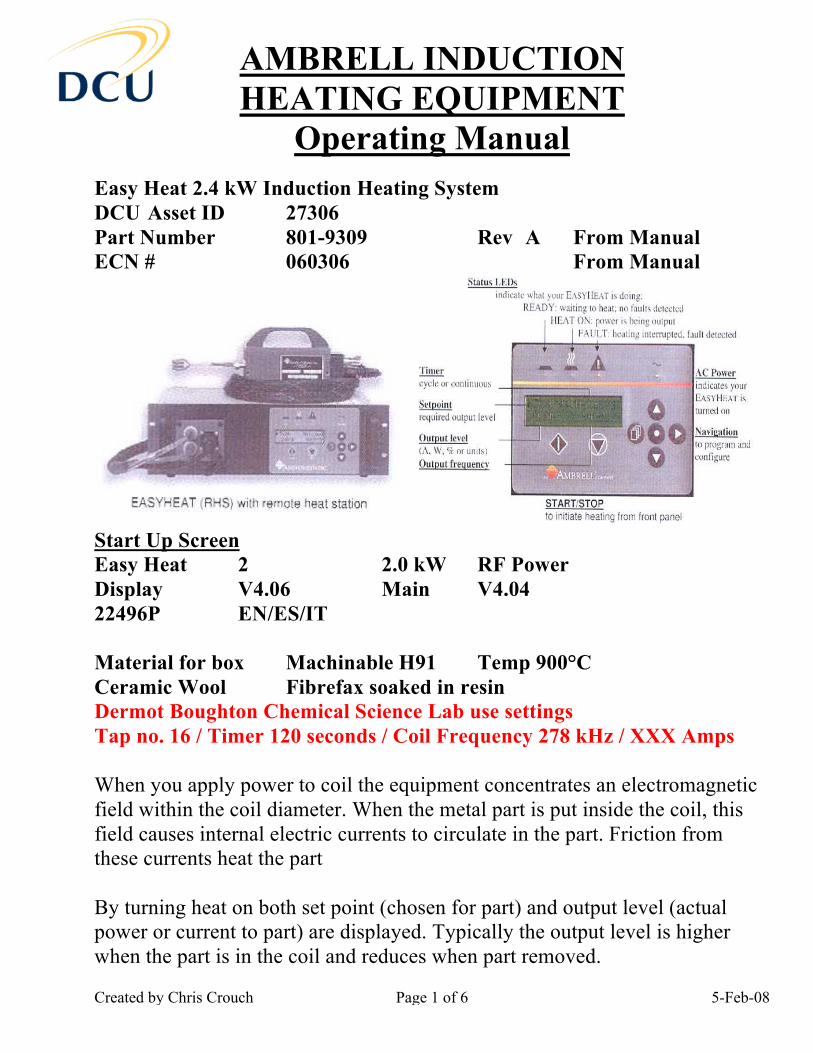
Easy Heat 2.4 kW Induction Heating System DCU Asset ID 27306 Part Number 801-9309 Rev A From Manual ECN # 060306 From Manual
Start Up Screen Easy Heat 2 2.0 kW RF Power Display V4.06 Main V4.04 22496P EN/ES/IT Material for box Machinable H91 Temp 900°C Ceramic Wool Fibrefax soaked in resin Dermot Boughton Chemical Science Lab use settings Tap no. 16 / Timer 120 seconds / Coil Frequency 278 kHz / XXX Amps When you apply power to coil the equipment concentrates an electromagnetic field within the coil diameter. When the metal part is put inside the coil, this field causes internal electric currents to circulate in the part. Friction from these currents heat the part By turning heat on both set point (chosen for part) and output level (actual power or current to part) are displayed. Typically the output level is higher when the part is in the coil and reduces when part removed.
AMBRELL INDUCTION HEATING EQUIPMENT
Operating Manual
Created by Chris Crouch Page 2 of 6 5-Feb-08
Safety Considerations High Temperature: Wear suitable gloves and clothing to stop direct contact with work piece or coil. Severe burns can result from contact high temperatures. RF Voltages: Wear suitable gloves and clothing to stop direct contact with work piece or coil. Induction Burns: the energized work coil causes nearby [200mm] metals to become heated. DO NOT WEAR JEWELRY OR CARRY KEYS Coil attached to Remote Heat Station (RHS) [Coil specific to heating process]. At back of RHS can change transformer settings, see manual or diagram on wire cover. Transformer settings control power output. Add Metal to Graphite crucible for melting size A1 dia 80 mm ht 100 mm Add fibrefax around crucible Place coil in Safety box and align centrally over movable base Place crucible and fibrefax centrally inside coil Add fibrefax around outside of coil to retain heat Add top plate to safety box Add a ceramic board cover over crucible during heat cycle [200 mm square] Turn on power to chiller unit, button attached to side of unit Check water flowing through pipes and no leaks
AMBRELL INDUCTION HEATING EQUIPMENT
Operating Manual
Created by Chris Crouch Page 3 of 6 5-Feb-08
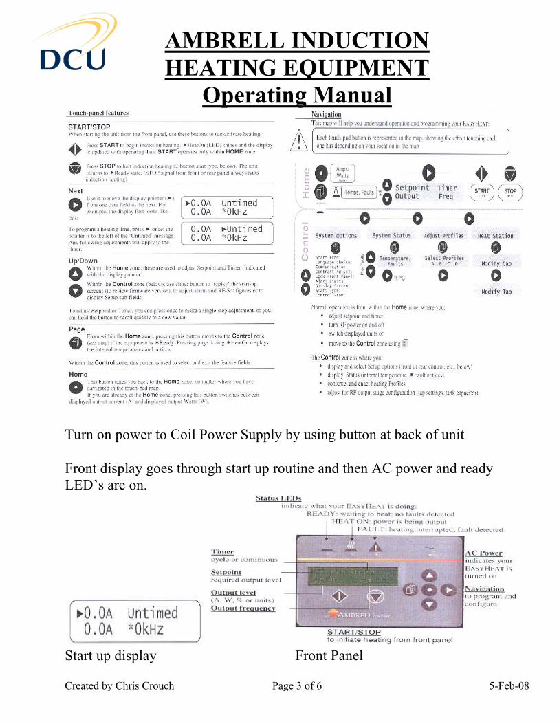
Turn on power to Coil Power Supply by using button at back of unit Front display goes through start up routine and then AC power and ready LED’s are on.
Start up display Front Panel
AMBRELL INDUCTION HEATING EQUIPMENT
Operating Manual
Created by Chris Crouch Page 4 of 6 5-Feb-08
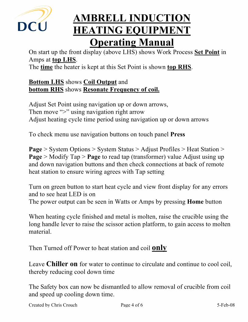
On start up the front display (above LHS) shows Work Process Set Point in Amps at top LHS. The time the heater is kept at this Set Point is shown top RHS. Bottom LHS shows Coil Output and bottom RHS shows Resonate Frequency of coil. Adjust Set Point using navigation up or down arrows, Then move “>” using navigation right arrow Adjust heating cycle time period using navigation up or down arrows To check menu use navigation buttons on touch panel Press Page > System Options > System Status > Adjust Profiles > Heat Station > Page > Modify Tap > Page to read tap (transformer) value Adjust using up and down navigation buttons and then check connections at back of remote heat station to ensure wiring agrees with Tap setting Turn on green button to start heat cycle and view front display for any errors and to see heat LED is on The power output can be seen in Watts or Amps by pressing Home button When heating cycle finished and metal is molten, raise the crucible using the long handle lever to raise the scissor action platform, to gain access to molten material. Then Turned off Power to heat station and coil only Leave Chiller on for water to continue to circulate and continue to cool coil, thereby reducing cool down time The Safety box can now be dismantled to allow removal of crucible from coil and speed up cooling down time.
AMBRELL INDUCTION HEATING EQUIPMENT
Operating Manual
Created by Chris Crouch Page 5 of 6 5-Feb-08
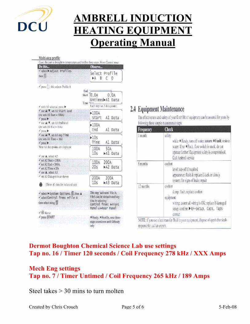
Dermot Boughton Chemical Science Lab use settings Tap no. 16 / Timer 120 seconds / Coil Frequency 278 kHz / XXX Amps Mech Eng settings Tap no. 7 / Timer Untimed / Coil Frequency 265 kHz / 189 Amps Steel takes > 30 mins to turn molten
AMBRELL INDUCTION HEATING EQUIPMENT
Operating Manual
Created by Chris Crouch Page 6 of 6 5-Feb-08
Optimum distance of crucible to coil is 10 mm as distance doubles the power output is reduced by a quarter Use crucibles with high carbon / Graphite content as it produces better heating conditions. Coil coated in blue epoxy powder coating, which may degrade over time but will not affect coil efficiency Induction heating principle produces magnetic coil hysterysis and Eddy Current field s to heat crucible and metal. After 700°C the magnetic heating effect is lost and heating produced by Eddy Current only. Aluminium will not heat up inside coil unless inside graphite crucible as has low resistance about value 6 (where steel has value of 120). Power Supply Unit Serial No.: EH1178 Part No.: 300C0002S Serial No.: 104386C 8010002S Equipment: EH 224 Despatch: 20/02/09 Sales O/N: 6226 Remote Heater Station Part No.: 301C0002 Serial No.: 106665C07090002 Equipment: Easy Heat Workhead 300P Capacitor Specification 2 x 0.33=0.66µF Pt No.: 012C0065 Despatch: Feb 08 Sales O/N: 6226 Chiller Part No.: 052C0001 Serial No.: 001113C07090001 Equipment: Flowmax 230 Despatch: 29/02/09 Sales O/N: 6226