Embed Size (px)
Citation preview
U of I Seminar Page 1 TAK 9 / 16 / 2016
Inductions Motors
Overview of history, physical design, basic theory, and
performance with emphasis on aircraft applications
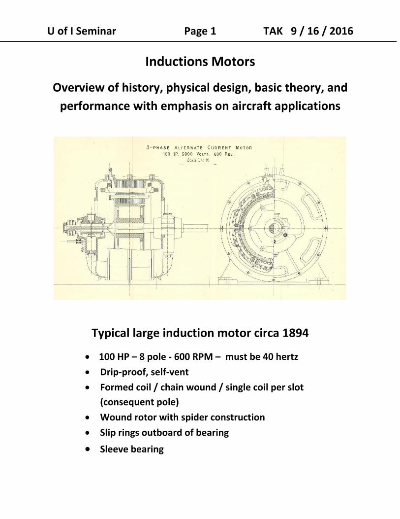
Typical large induction motor circa 1894
100 HP – 8 pole ‐ 600 RPM – must be 40 hertz
Drip‐proof, self‐vent
Formed coil / chain wound / single coil per slot
(consequent pole)
Wound rotor with spider construction
Slip rings outboard of bearing
Sleeve bearing
U of I Seminar Page 2 TAK 9 / 16 / 2016
1. Description, configuration, features ‐ Other names are asynchronous or squirrel cage motor
‐ Only one of the windings is excited with electrical
input as a requirement
‐ Does it even have a winding on the rotor?
‐ It’s like a transformer with an air gap and the
secondary is shorted out and spins
‐ It’s like a clutch being ridden all the time
‐ It’s simple and robust
‐ It’s synonymous with 3 phase, polyphase, and rotary
magnetic field
‐ One of the 10 best discoveries in the last 130 years.
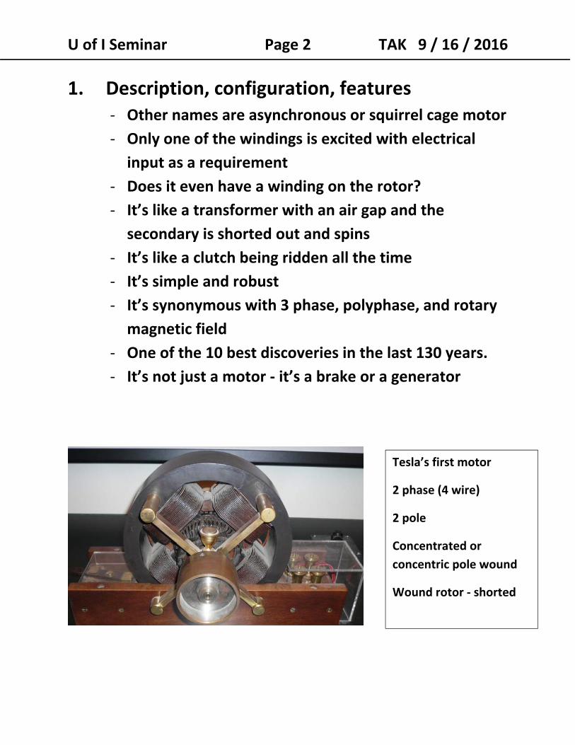
‐ It’s not just a motor ‐ it’s a brake or a generator
Tesla’s first motor
2 phase (4 wire)
2 pole
Concentrated or
concentric pole wound
Wound rotor ‐ shorted
U of I Seminar Page 3 TAK 9 / 16 / 2016
Induction motors comprise of the following
electrical / magnetic elements:
Stator – the only part normally connected to external electrical
power. Most commonly on the exterior and almost always
stationary.
Stator winding are three phase or single phase today and carry
full power of the motor.
Stators have laminated cores and most have slots for the coils ‐
either formed coils or random wound coils. It’s hard to tell
induction motor and traditional synchronous stators apart.
Early machines quickly moved to the modern stator
configuration.
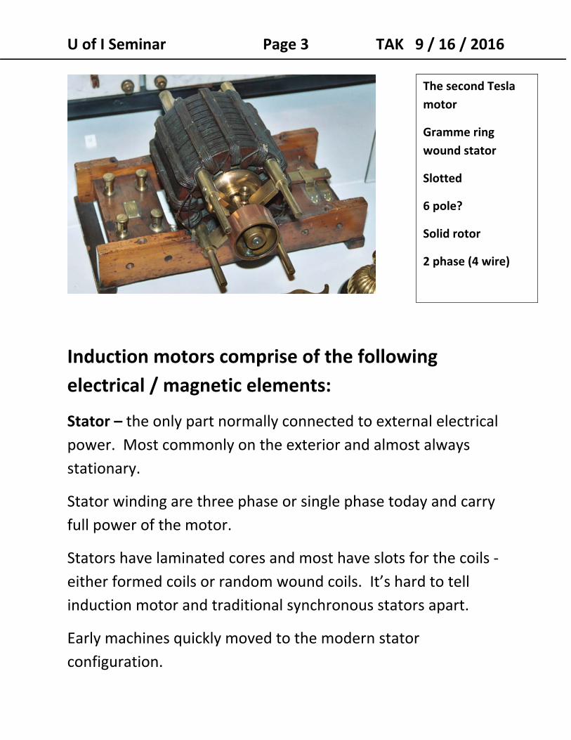
The second Tesla
motor
Gramme ring
wound stator
Slotted
6 pole?
Solid rotor
2 phase (4 wire)
U of I Seminar Page 4 TAK 9 / 16 / 2016 Rotor – the rotor need not receive external power or excitation
other than from the stator.
Most rotors are “squirrel cage”‐ consisting of bars that are
shorted together on each end to “end rings”.
Cage rotors are cast or fabricated of aluminum, copper, or
other metals. Most rotors have no insulation.
Wound rotors have winding schemes similar to stators –
typically wound for 3 phases and with a pole count matching
the stator.
Slip rings are used to connect a wound rotor to external
resistance to change the motor speed / torque characteristic.
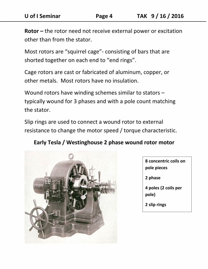
Early Tesla / Westinghouse 2 phase wound rotor motor
8 concentric coils on
pole pieces
2 phase
4 poles (2 coils per
pole)
2 slip rings
U of I Seminar Page 5 TAK 9 / 16 / 2016
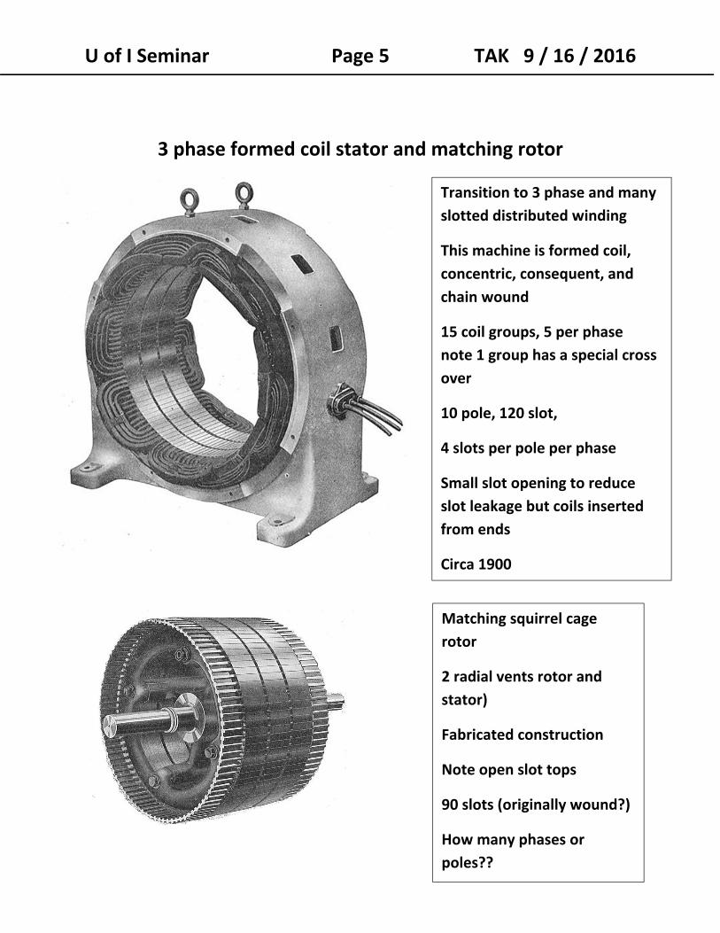
3 phase formed coil stator and matching rotor
Transition to 3 phase and many
slotted distributed winding
This machine is formed coil,
concentric, consequent, and
chain wound
15 coil groups, 5 per phase
note 1 group has a special cross
over
10 pole, 120 slot,
4 slots per pole per phase
Small slot opening to reduce
slot leakage but coils inserted
from ends
Circa 1900
Matching squirrel cage
rotor
2 radial vents rotor and
stator)
Fabricated construction
Note open slot tops
90 slots (originally wound?)
How many phases or
poles??
U of I Seminar Page 6 TAK 9 / 16 / 2016
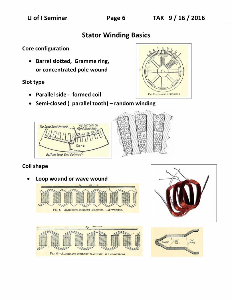
Stator Winding Basics
Core configuration
Barrel slotted, Gramme ring,
or concentrated pole wound
Slot type
Parallel side ‐ formed coil
Semi‐closed ( parallel tooth) – random winding
Coil shape
Loop wound or wave wound
U of I Seminar Page 7 TAK 9 / 16 / 2016
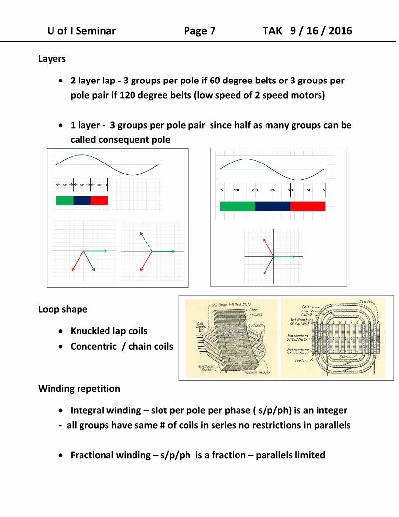
Layers
2 layer lap ‐ 3 groups per pole if 60 degree belts or 3 groups per pole pair if 120 degree belts (low speed of 2 speed motors)
1 layer ‐ 3 groups per pole pair since half as many groups can be
called consequent pole
Loop shape
Knuckled lap coils Concentric / chain coils
Winding repetition
Integral winding – slot per pole per phase ( s/p/ph) is an integer ‐ all groups have same # of coils in series no restrictions in parallels
Fractional winding – s/p/ph is a fraction – parallels limited
U of I Seminar Page 8 TAK 9 / 16 / 2016
Winding factors
Pitch factor – Kp: Coil embrace, pitch, or throw – what part of
pole pitch is covered. Sine of 90 degrees x embrace.
Distribution factor ‐ Kd‐ phase effect of adjacent coils in a group in series ‐ never less than 3/π (.955) for 60 degree belts.
Connection ‐ parallel groups, series groups, wye or delta.
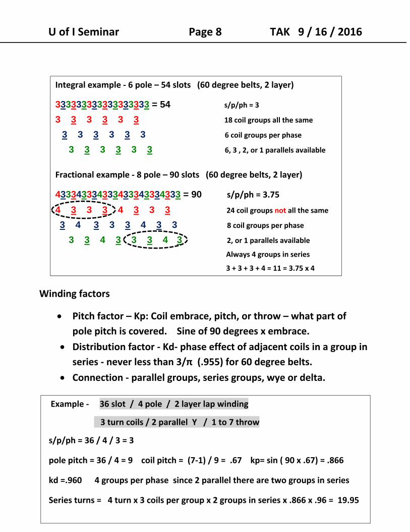
Integral example ‐ 6 pole – 54 slots (60 degree belts, 2 layer)
333333333333333333 = 54 s/p/ph = 3
3 3 3 3 3 3 18 coil groups all the same
3 3 3 3 3 3 6 coil groups per phase
3 3 3 3 3 3 6, 3 , 2, or 1 parallels available
Fractional example ‐ 8 pole – 90 slots (60 degree belts, 2 layer)
433343334333433343334333 = 90 s/p/ph = 3.75
4 3 3 3 4 3 3 3 24 coil groups not all the same
3 4 3 3 3 4 3 3 8 coil groups per phase
3 3 4 3 3 3 4 3 2, or 1 parallels available
Always 4 groups in series
3 + 3 + 3 + 4 = 11 = 3.75 x 4
Example ‐ 36 slot / 4 pole / 2 layer lap winding
3 turn coils / 2 parallel Y / 1 to 7 throw
s/p/ph = 36 / 4 / 3 = 3
pole pitch = 36 / 4 = 9 coil pitch = (7‐1) / 9 = .67 kp= sin ( 90 x .67) = .866
kd =.960 4 groups per phase since 2 parallel there are two groups in series
Series turns = 4 turn x 3 coils per group x 2 groups in series x .866 x .96 = 19.95
U of I Seminar Page 9 TAK 9 / 16 / 2016
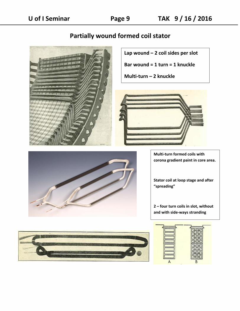
Partially wound formed coil stator
Lap wound – 2 coil sides per slot
Bar wound = 1 turn = 1 knuckle
Multi‐turn – 2 knuckle
Multi‐turn formed coils with
corona gradient paint in core area.
Stator coil at loop stage and after
“spreading”
2 – four turn coils in slot, without
and with side‐ways stranding
U of I Seminar Page 10 TAK 9 / 16 / 2016
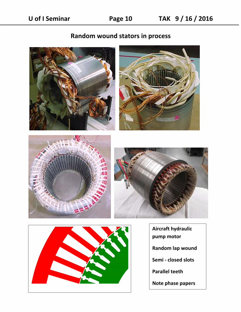
Random wound stators in process
Aircraft hydraulic
pump motor
Random lap wound
Semi ‐ closed slots
Parallel teeth
Note phase papers
U of I Seminar Page 11 TAK 9 / 16 / 2016
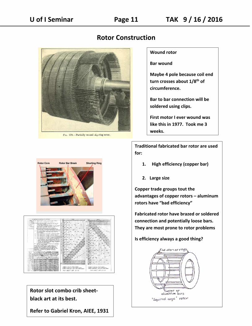
Rotor Construction
Wound rotor
Bar wound
Maybe 4 pole because coil end
turn crosses about 1/8th of
circumference.
Bar to bar connection will be
soldered using clips.
First motor I ever wound was
like this in 1977. Took me 3
weeks.
Traditional fabricated bar rotor are used
for:
1. High efficiency (copper bar)
2. Large size
Copper trade groups tout the
advantages of copper rotors – aluminum
rotors have “bad efficiency”
Fabricated rotor have brazed or soldered
connection and potentially loose bars.
They are most prone to rotor problems
Is efficiency always a good thing?
Rotor slot combo crib sheet‐
black art at its best.
Refer to Gabriel Kron, AIEE, 1931
U of I Seminar Page 12 TAK 9 / 16 / 2016
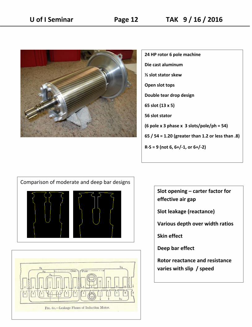
Comparison of moderate and deep bar designs
Slot opening – carter factor for
effective air gap
Slot leakage (reactance)
Various depth over width ratios
Skin effect
Deep bar effect
Rotor reactance and resistance
varies with slip / speed
24 HP rotor 6 pole machine
Die cast aluminum
½ slot stator skew
Open slot tops
Double tear drop design
65 slot (13 x 5)
56 slot stator
(6 pole x 3 phase x 3 slots/pole/ph = 54)
65 / 54 = 1.20 (greater than 1.2 or less than .8)
R‐S = 9 (not 6, 6+/‐1, or 6+/‐2)
U of I Seminar Page 13 TAK 9 / 16 / 2016
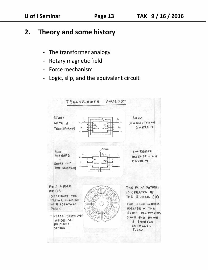
2. Theory and some history
‐ The transformer analogy
‐ Rotary magnetic field
‐ Force mechanism
‐ Logic, slip, and the equivalent circuit
U of I Seminar Page 14 TAK 9 / 16 / 2016
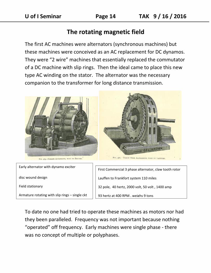
The rotating magnetic field
The first AC machines were alternators (synchronous machines) but
these machines were conceived as an AC replacement for DC dynamos.
They were “2 wire” machines that essentially replaced the commutator
of a DC machine with slip rings. Then the ideal came to place this new
type AC winding on the stator. The alternator was the necessary
companion to the transformer for long distance transmission.
To date no one had tried to operate these machines as motors nor had
they been paralleled. Frequency was not important because nothing
“operated” off frequency. Early machines were single phase ‐ there
was no concept of multiple or polyphases.
Early alternator with dynamo exciter
disc wound design
Field stationary
Armature rotating with slip rings – single ckt
First Commercial 3 phase alternator, claw tooth rotor
Lauffen to Frankfort system 110 miles
32 pole, 40 hertz, 2000 volt, 50 volt , 1400 amp
93 hertz at 400 RPM , weighs 9 tons
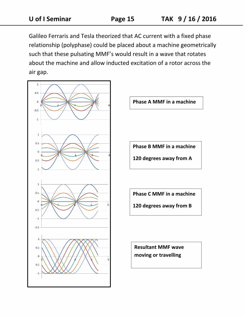
U of I Seminar Page 15 TAK 9 / 16 / 2016 Galileo Ferraris and Tesla theorized that AC current with a fixed phase
relationship (polyphase) could be placed about a machine geometrically
such that these pulsating MMF’s would result in a wave that rotates
about the machine and allow inducted excitation of a rotor across the
air gap.
Phase A MMF in a machine
Phase B MMF in a machine
120 degrees away from A
Phase C MMF in a machine
120 degrees away from B
Resultant MMF wave
moving or travelling
U of I Seminar Page 16 TAK 9 / 16 / 2016 The result of this idea lead to 3 advancements:
1. The idea that polyphases would allow for a traveling MMF that could be put to use . Mikhail Dolivo‐Dobrovolsky showed three phases (Drehstrom) was more practical than two phase. “AC” was already identified as having a separate advantage because it allowed high voltage distribution via transformers.
2. The invention of the induction motor nearly simultaneously by Galileo Ferraris and Tesla. (Later Mikhail Dolivo‐Dobrovolsky simplified the motor with the squirrel cage rotor.)
3. The understanding that the alternator could also operate as a synchronous motor.
Tesla or Ferraris and who else?
Walter Bailey – 1879 – demonstrated a 2 phase device powered by dry cells and a hand crank commutator.
Ferraris demonstrated polyphase and rotating magnetic fields in 1885. He built induction type motor prior to Tesla.
Tesla received a US patent on May 1st 1888. He made great prototypes and presented the motor like a showman at technical gatherings.
Dolivo‐Dobrovolsky added a lot to practicality – 3 phase theory and rotor construction.
Behrend and De La Tour published practical theory and the circle diagram in 1901.
Steinmetz provided the equivalent circuit we use today ‐ replacing the more complete Heyland circle diagram.
By 1911, Bailey’s book – The induction Motor summarizes modern theory.
U of I Seminar Page 17 TAK 9 / 16 / 2016
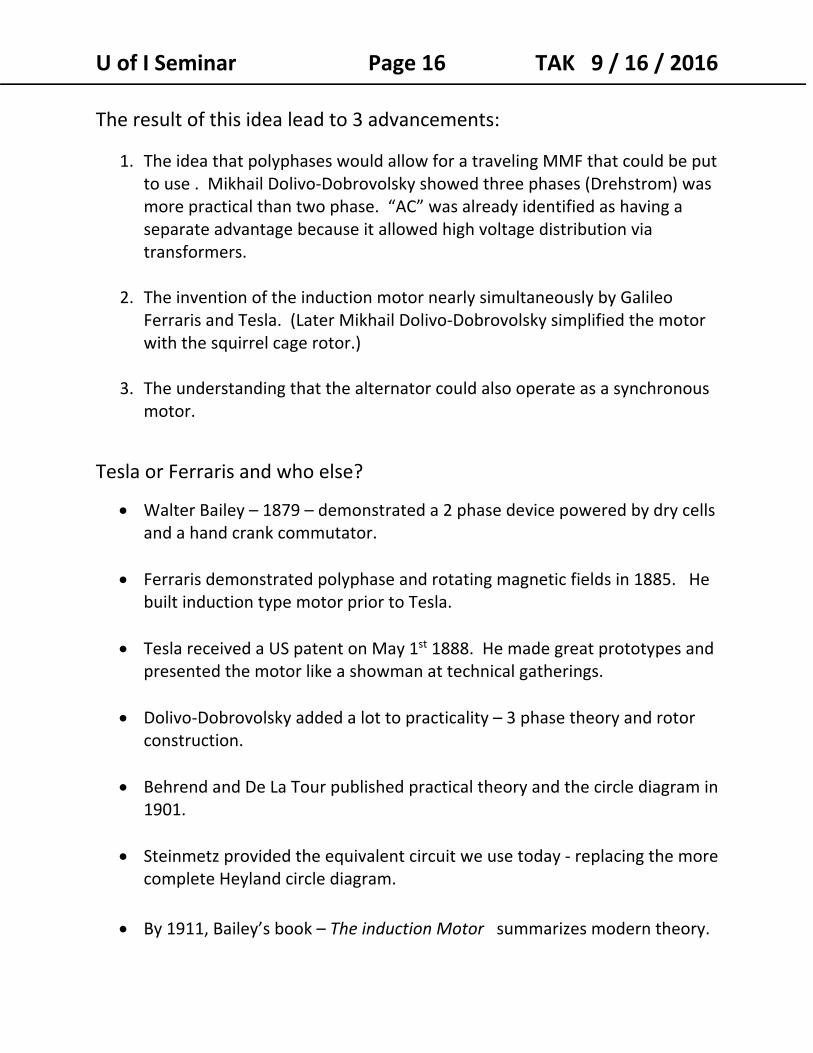
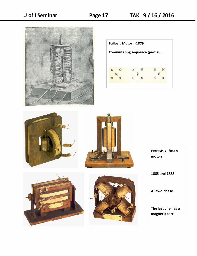
Ferrasis’s first 4
motors
1885 and 1886
All two phase
The last one has a
magnetic core
Bailey’s Motor ‐1879
Commutating sequence (partial):
U of I Seminar Page 18 TAK 9 / 16 / 2016
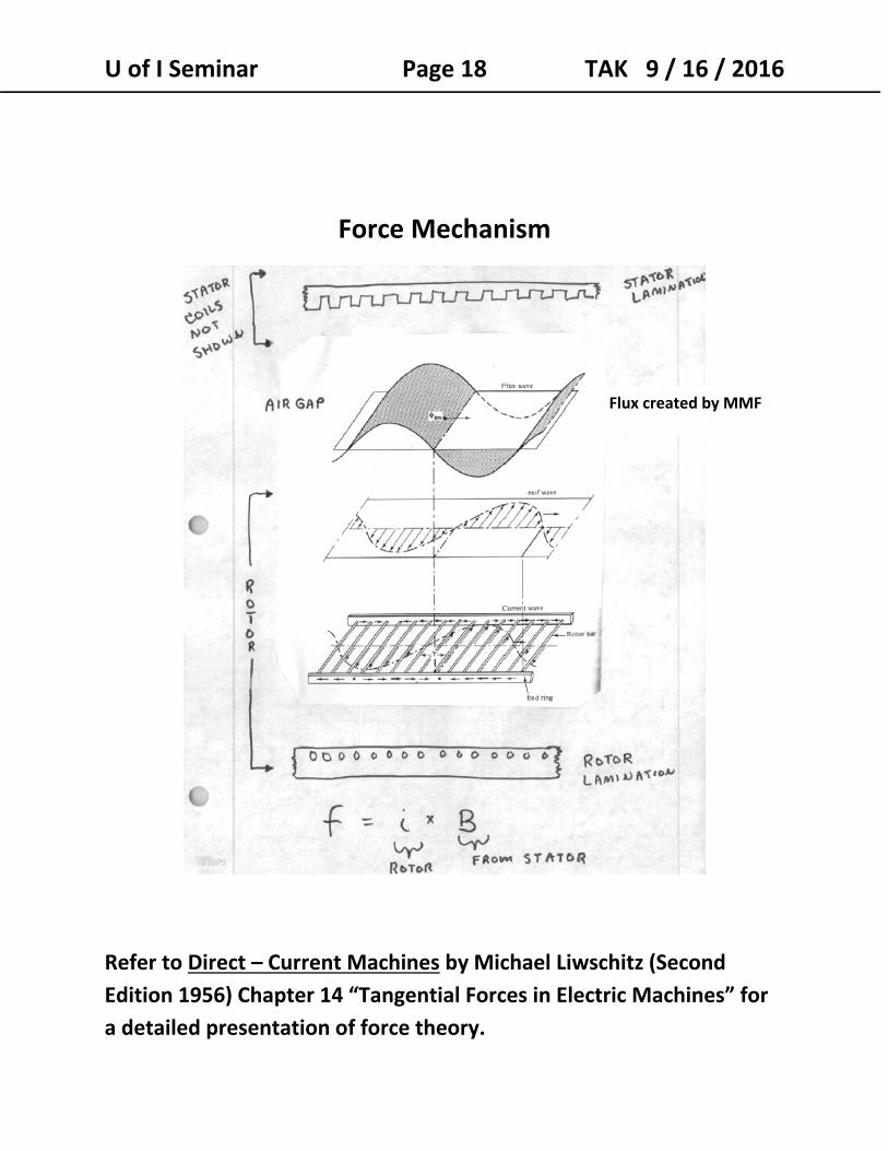
Force Mechanism
Refer to Direct – Current Machines by Michael Liwschitz (Second
Edition 1956) Chapter 14 “Tangential Forces in Electric Machines” for
a detailed presentation of force theory.
Flux created by MMF
U of I Seminar Page 19 TAK 9 / 16 / 2016
Logic, Slip and the Equivalent Circuit
The MMF and flux wave of an induction motor travel the same way that
they do in a synchronous machine thus:
RPM (synchronous) = 120 x Frequency / poles
If the rotor of an induction motor travel exactly in step with the stator‐
created field, then the flux looks to be at stand still when viewed from
the rotor.
If this is the case then no voltage / current can be induced in the rotor
and it can produce no torque to keep itself spinning in lock step with
the field wave.
Induction motors never operate at synchronous speed under their own
power.
When motoring, induction motor run below synchronous speed or are
slipping relative to synchronous speed.
Slip ( S ) = (synchronous speed – actual speed)
synchronous speed
U of I Seminar Page 20 TAK 9 / 16 / 2016
At synchronous speed slip = 0 or 0%
At stall / locked rotor slip = 1.0 or 100%
Example: a 4 pole 60 hertz motor runs at 1740 RPM
RPM synchronous = 120 x 60 / 4 = 1800 RPM
Slip = ( 1800 ‐1740) / 1800 = 60 / 1800 = .033 = 3.3%
Rotor electrical frequency = slip x stator frequency
At synchronous speed Slip = 0, rotor frequency = 0, (No frequency, no induction)
At stall slip =1, rotor frequency = line frequency For our example above rotor frequency = .033 x 60 hz = 2 hertz
Rotors can be made of lower grade steel since operating
frequency is low (and losses are low).
It easy to observe that as load is increased in an induction motor that it
slows down a bit just like DC motors.
The induction motor equivalent circuit is a combination of the
transformer equivalent circuit and the idea of slip. It was developed by
Steinmetz. Prior to the equivalent circuit, motor performance was
calculated using the circle diagram.
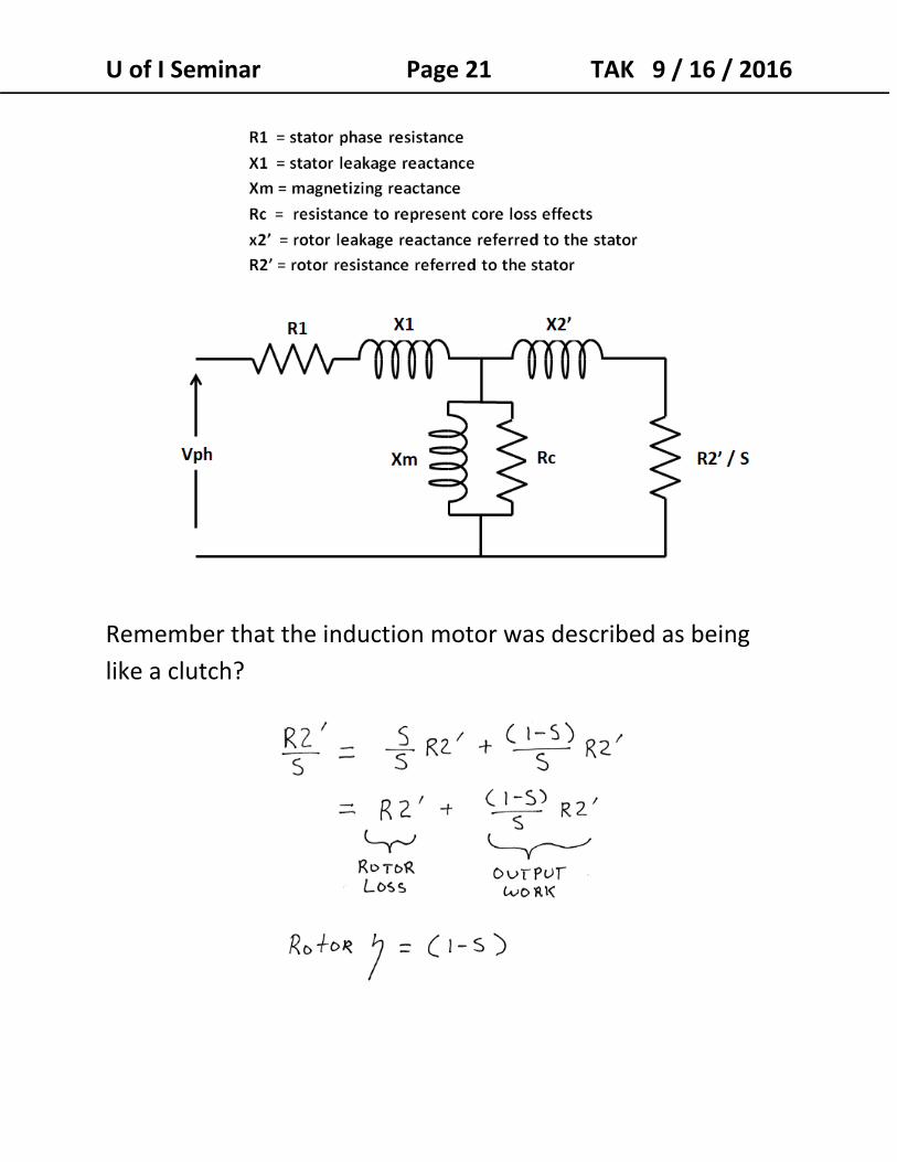
U of I Seminar Page 21 TAK 9 / 16 / 2016
Remember that the induction motor was described as being
like a clutch?
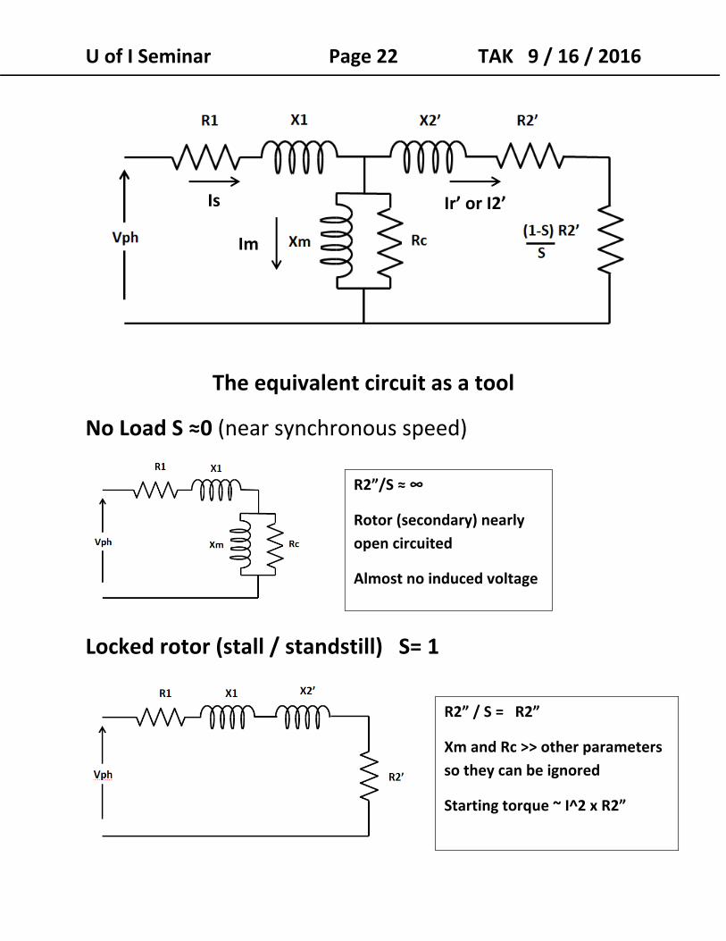
U of I Seminar Page 22 TAK 9 / 16 / 2016
The equivalent circuit as a tool
No Load S ≈0 (near synchronous speed)
Locked rotor (stall / standstill) S= 1
R2”/S ≈ ∞
Rotor (secondary) nearly
open circuited
Almost no induced voltage
R2” / S = R2”
Xm and Rc >> other parameters
so they can be ignored
Starting torque ~ I^2 x R2”
Is
Im
Ir’ or I2’
U of I Seminar Page 23 TAK 9 / 16 / 2016
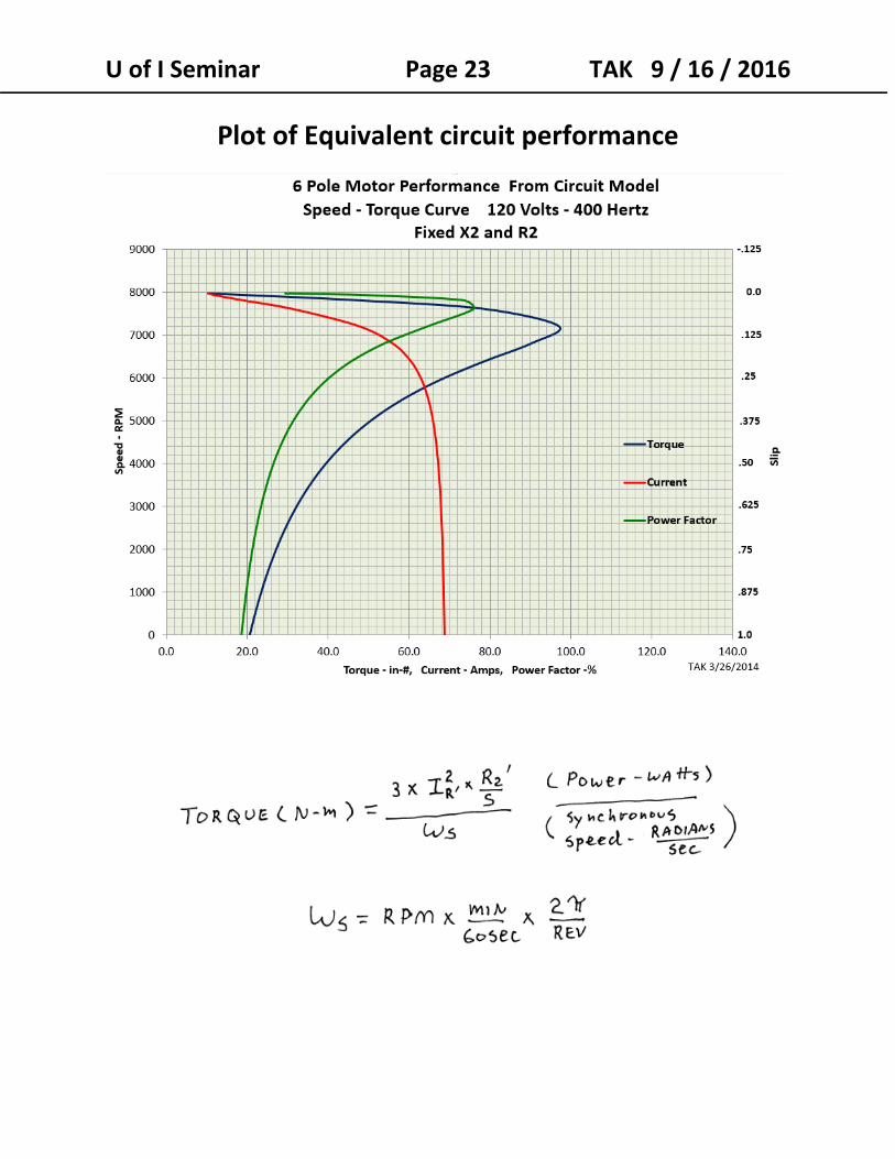
Plot of Equivalent circuit performance
U of I Seminar Page 24 TAK 9 / 16 / 2016
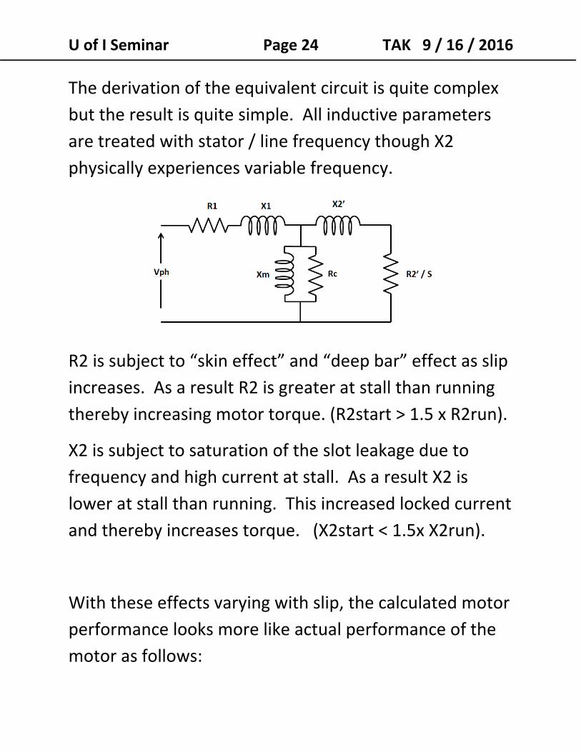
The derivation of the equivalent circuit is quite complex
but the result is quite simple. All inductive parameters
are treated with stator / line frequency though X2
physically experiences variable frequency.
R2 is subject to “skin effect” and “deep bar” effect as slip
increases. As a result R2 is greater at stall than running
thereby increasing motor torque. (R2start > 1.5 x R2run).
X2 is subject to saturation of the slot leakage due to
frequency and high current at stall. As a result X2 is
lower at stall than running. This increased locked current
and thereby increases torque. (X2start < 1.5x X2run).
With these effects varying with slip, the calculated motor
performance looks more like actual performance of the
motor as follows:
U of I Seminar Page 25 TAK 9 / 16 / 2016
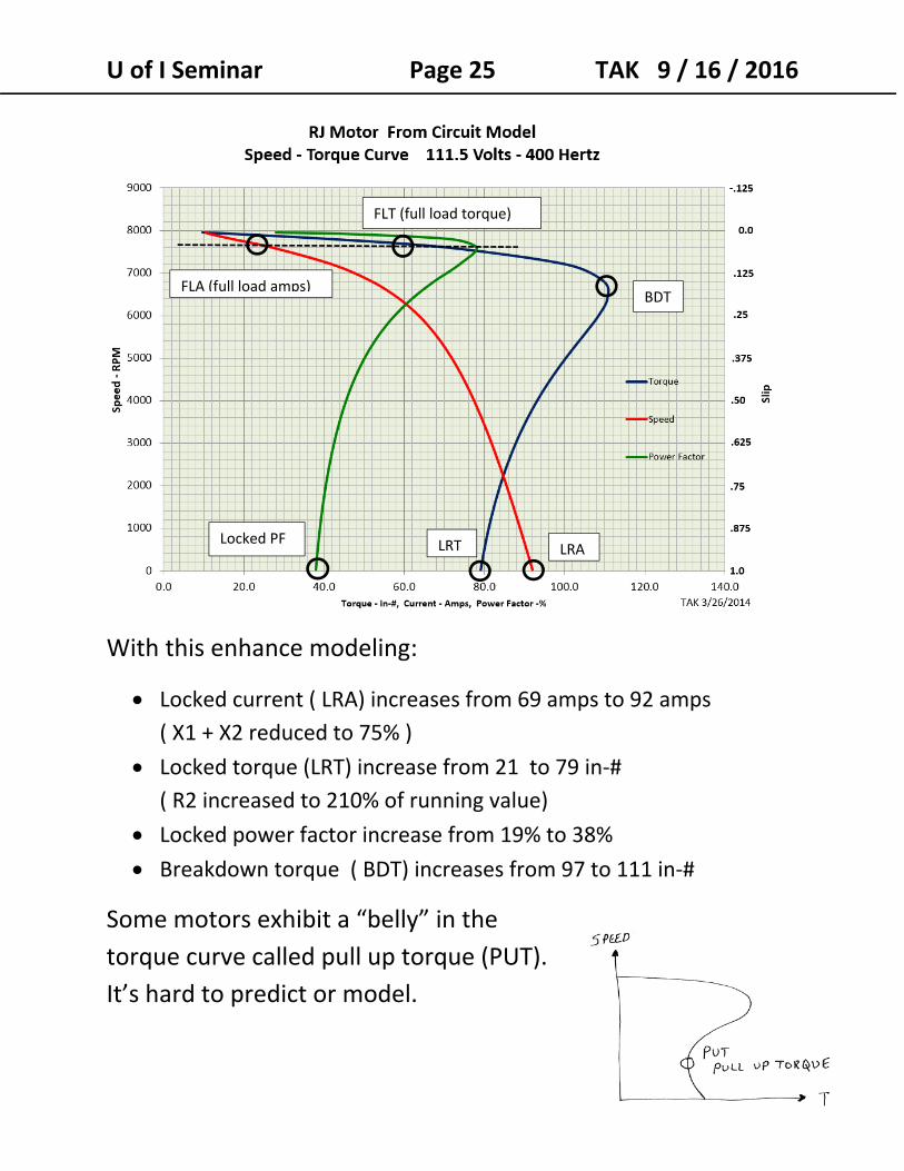
With this enhance modeling:
Locked current ( LRA) increases from 69 amps to 92 amps
( X1 + X2 reduced to 75% )
Locked torque (LRT) increase from 21 to 79 in‐#
( R2 increased to 210% of running value)
Locked power factor increase from 19% to 38%
Breakdown torque ( BDT) increases from 97 to 111 in‐#
Some motors exhibit a “belly” in the
torque curve called pull up torque (PUT).
It’s hard to predict or model.
BDT
LRALRTLocked PF
FLT (full load torque)
FLA (full load amps)
U of I Seminar Page 26 TAK 9 / 16 / 2016
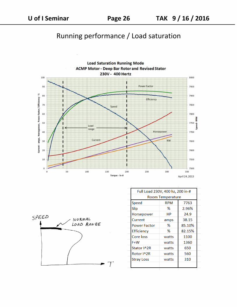
Running performance / Load saturation
U of I Seminar Page 27 TAK 9 / 16 / 2016
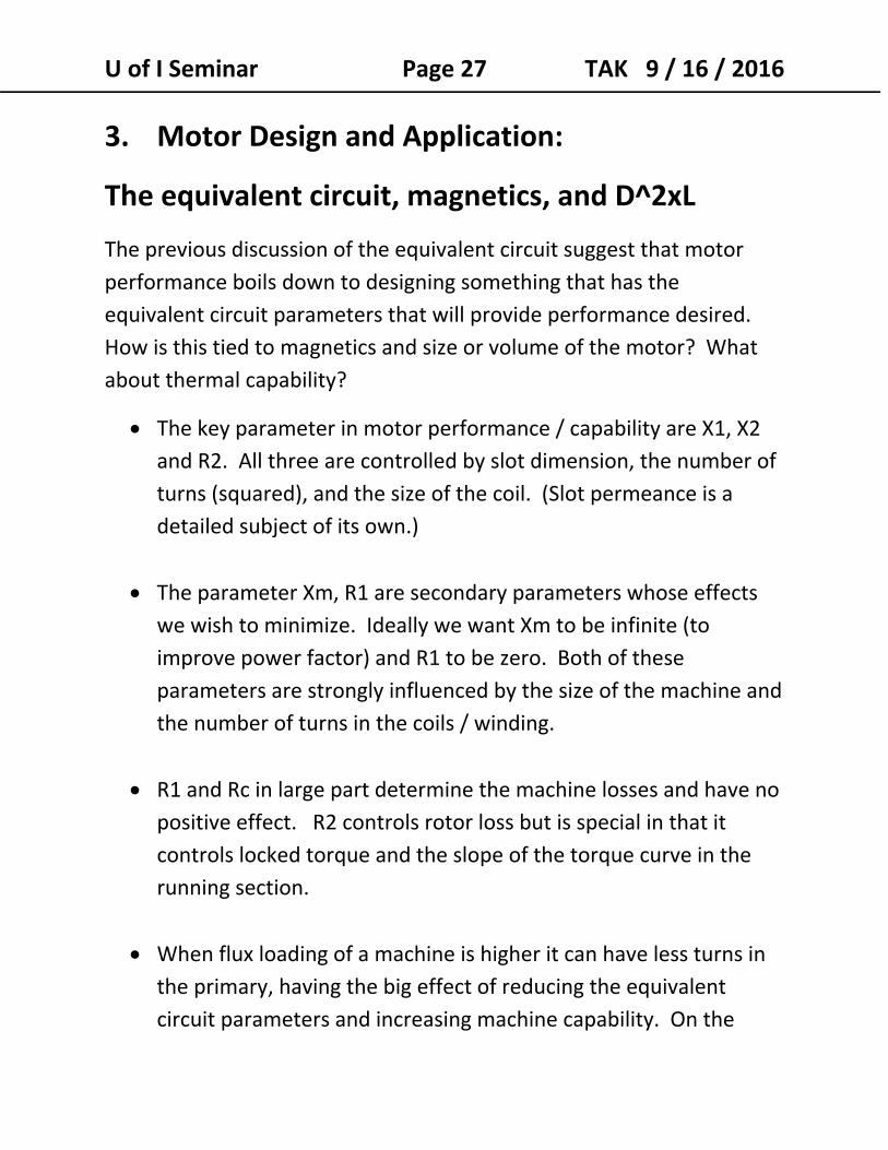
3. Motor Design and Application:
The equivalent circuit, magnetics, and D^2xL
The previous discussion of the equivalent circuit suggest that motor
performance boils down to designing something that has the
equivalent circuit parameters that will provide performance desired.
How is this tied to magnetics and size or volume of the motor? What
about thermal capability?
The key parameter in motor performance / capability are X1, X2
and R2. All three are controlled by slot dimension, the number of
turns (squared), and the size of the coil. (Slot permeance is a
detailed subject of its own.)
The parameter Xm, R1 are secondary parameters whose effects
we wish to minimize. Ideally we want Xm to be infinite (to
improve power factor) and R1 to be zero. Both of these
parameters are strongly influenced by the size of the machine and
the number of turns in the coils / winding.
R1 and Rc in large part determine the machine losses and have no
positive effect. R2 controls rotor loss but is special in that it
controls locked torque and the slope of the torque curve in the
running section.
When flux loading of a machine is higher it can have less turns in
the primary, having the big effect of reducing the equivalent
circuit parameters and increasing machine capability. On the
U of I Seminar Page 28 TAK 9 / 16 / 2016
down side increasing flux loading decreases Xm and Rc –
increasing magnetic losses.
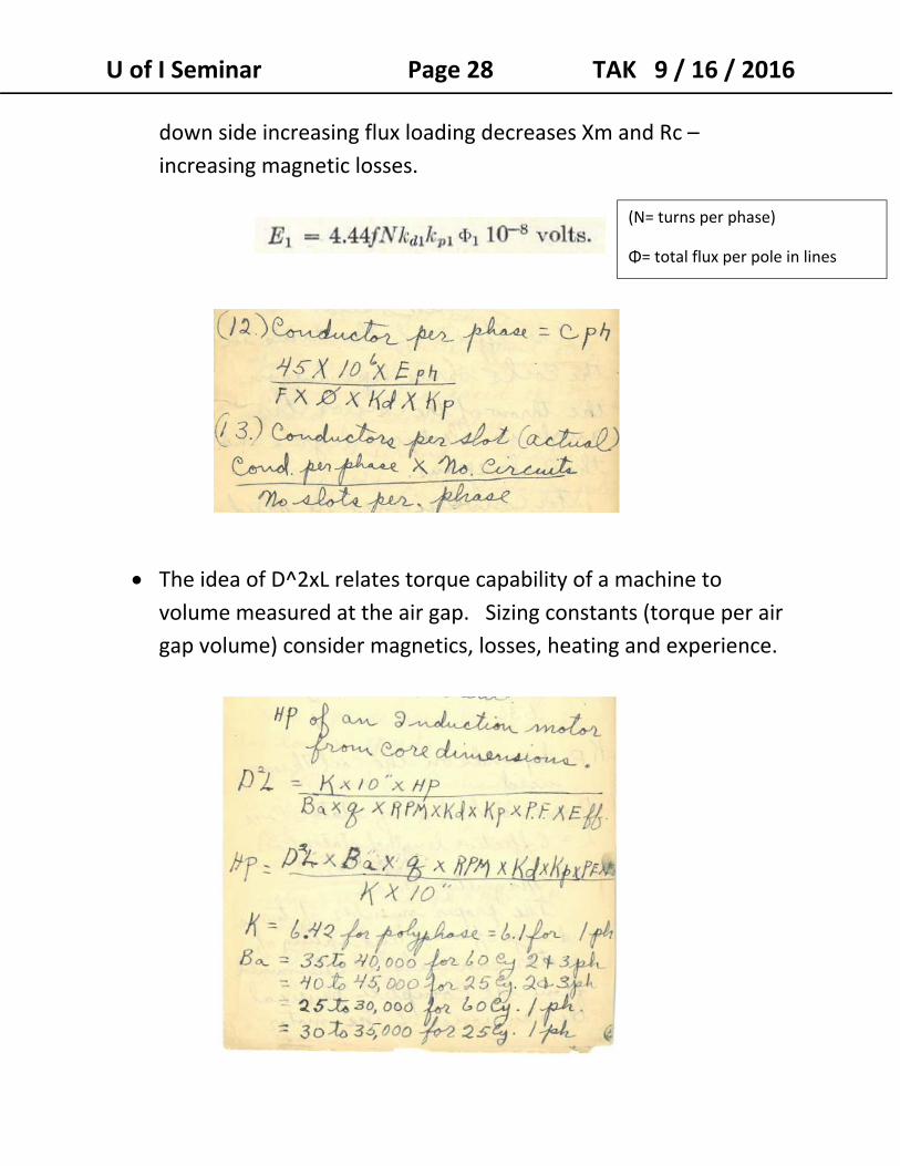
The idea of D^2xL relates torque capability of a machine to
volume measured at the air gap. Sizing constants (torque per air
gap volume) consider magnetics, losses, heating and experience.
(N= turns per phase)
Φ= total flux per pole in lines
U of I Seminar Page 29 TAK 9 / 16 / 2016
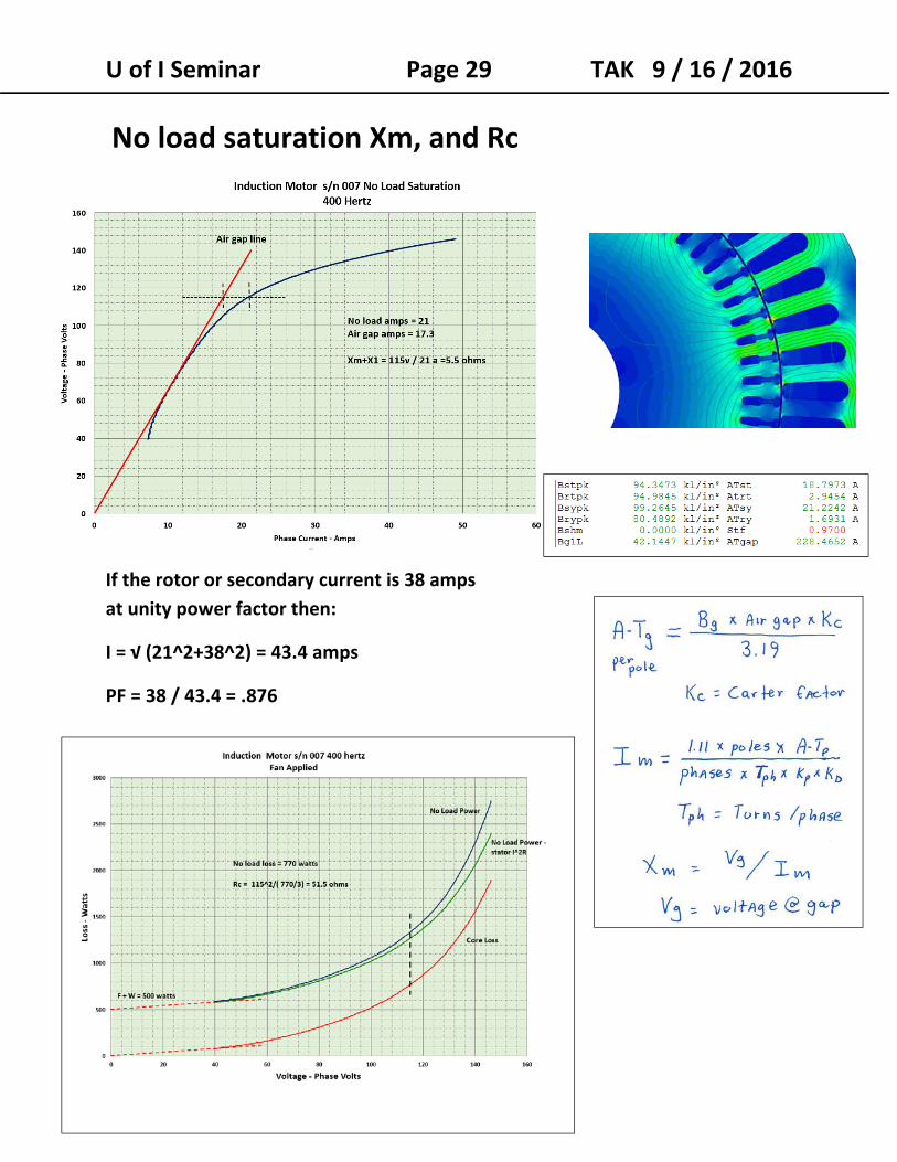
No load saturation Xm, and Rc
If the rotor or secondary current is 38 amps
at unity power factor then:
I = √ (21^2+38^2) = 43.4 amps
PF = 38 / 43.4 = .876
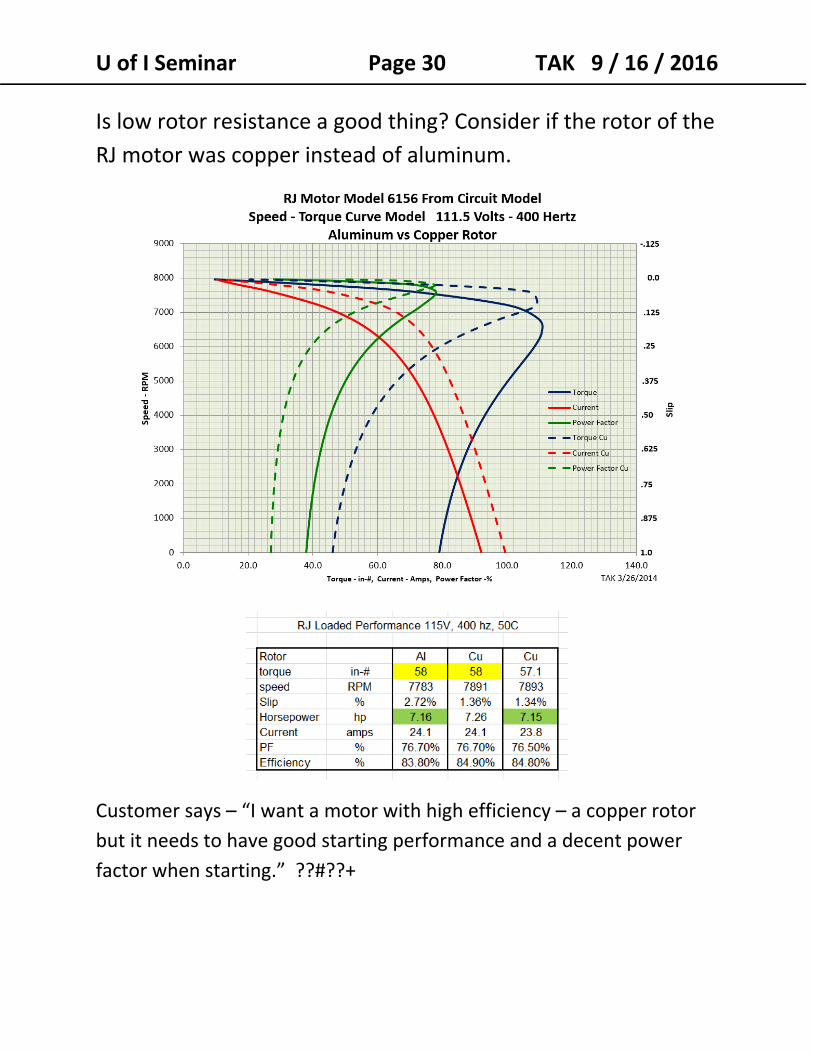
U of I Seminar Page 30 TAK 9 / 16 / 2016 Is low rotor resistance a good thing? Consider if the rotor of the
RJ motor was copper instead of aluminum.
Customer says – “I want a motor with high efficiency – a copper rotor
but it needs to have good starting performance and a decent power
factor when starting.” ??#??+
U of I Seminar Page 31 TAK 9 / 16 / 2016
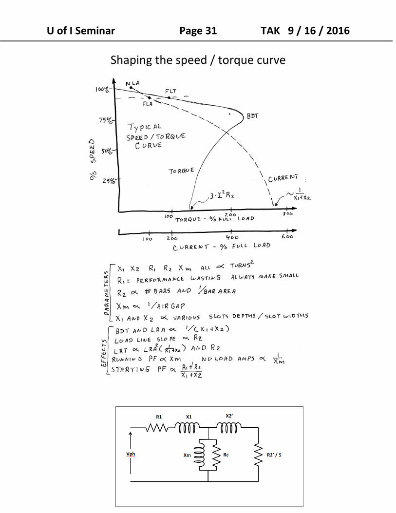
Shaping the speed / torque curve
U of I Seminar Page 32 TAK 9 / 16 / 2016
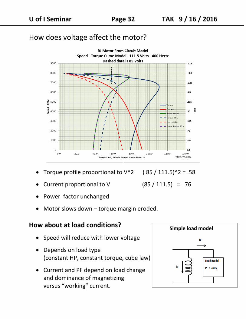
How does voltage affect the motor?
Torque profile proportional to V^2 ( 85 / 111.5)^2 = .58
Current proportional to V (85 / 111.5) = .76
Power factor unchanged
Motor slows down – torque margin eroded.
How about at load conditions?
Speed will reduce with lower voltage
Depends on load type (constant HP, constant torque, cube law)
Current and PF depend on load change and dominance of magnetizing versus “working” current.
Simple load model
U of I Seminar Page 33 TAK 9 / 16 / 2016
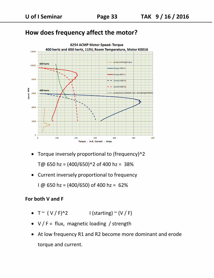
How does frequency affect the motor?
Torque inversely proportional to (frequency)^2
T@ 650 hz = (400/650)^2 of 400 hz = 38%
Current inversely proportional to frequency
I @ 650 hz = (400/650) of 400 hz = 62%
For both V and F
T ~ ( V / F)^2 I (starting) ~ (V / F)
V / F = flux, magnetic loading / strength
At low frequency R1 and R2 become more dominant and erode
torque and current.
U of I Seminar Page 34 TAK 9 / 16 / 2016
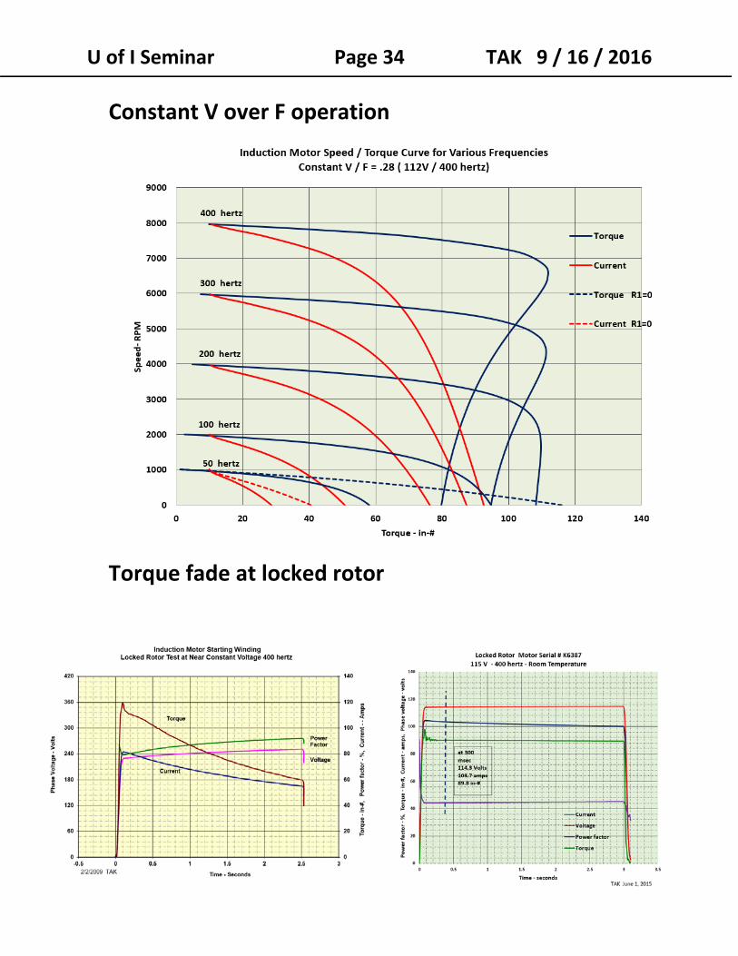
Constant V over F operation
Torque fade at locked rotor
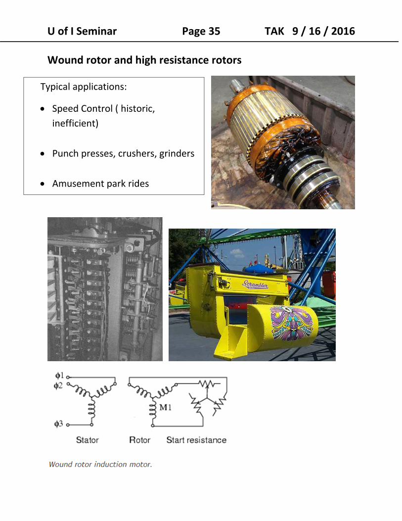
U of I Seminar Page 35 TAK 9 / 16 / 2016 Wound rotor and high resistance rotors
Typical applications:
Speed Control ( historic, inefficient)
Punch presses, crushers, grinders
Amusement park rides
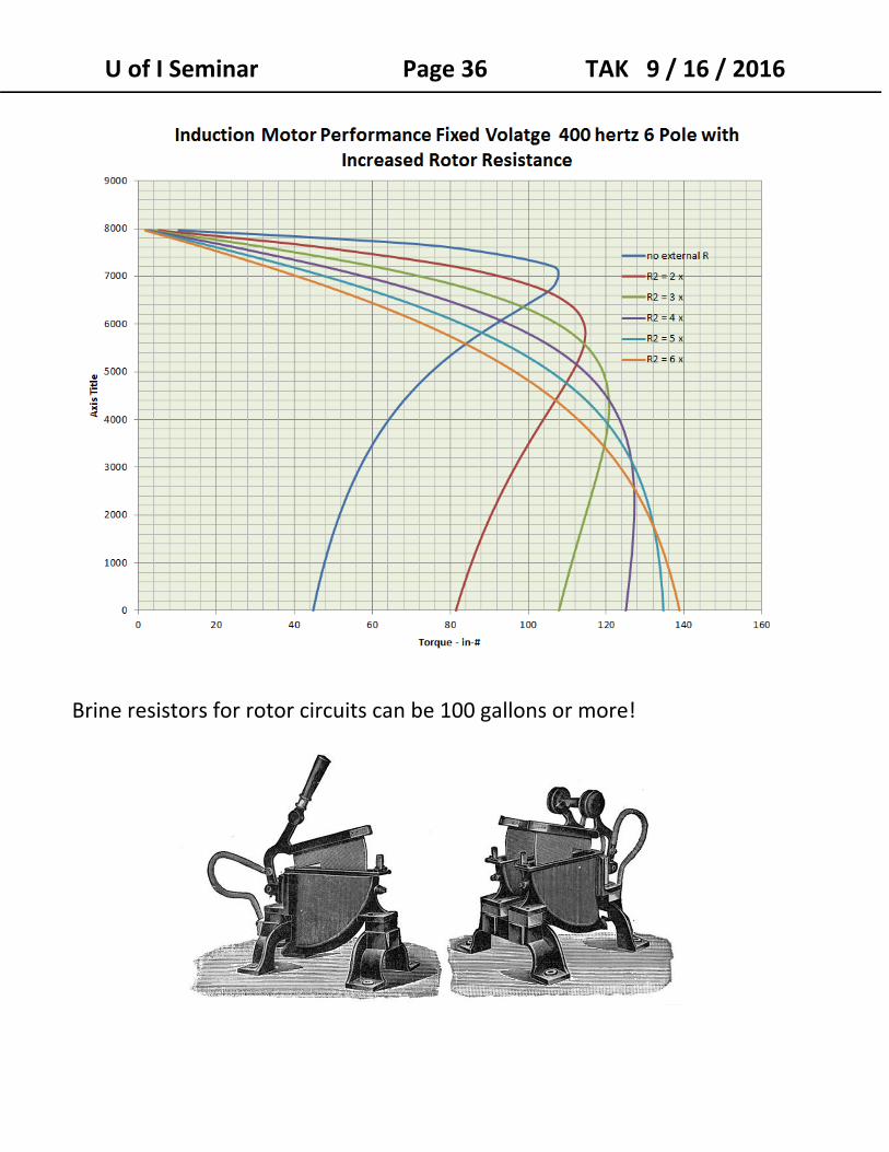
U of I Seminar Page 36 TAK 9 / 16 / 2016
Brine resistors for rotor circuits can be 100 gallons or more!
U of I Seminar Page 37 TAK 9 / 16 / 2016
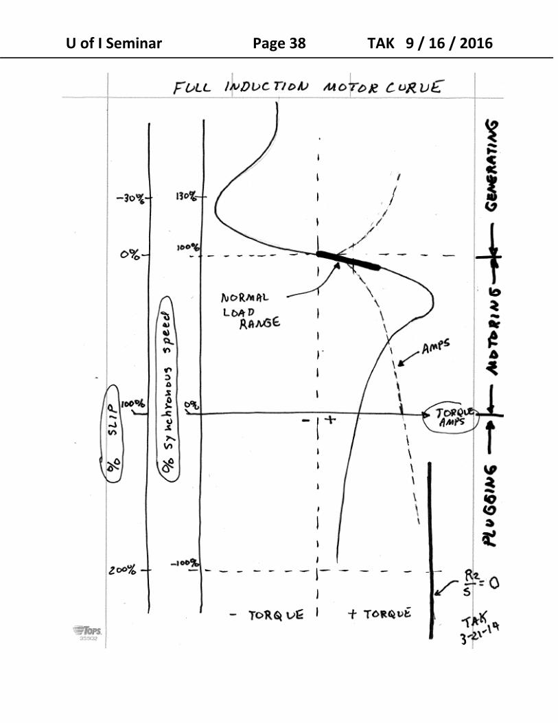
4. Motoring, Generating, and Braking / Plugging
So far we have talked about operation between standstill and
synchronous speed (1 to 0 slip).
But what about speeds above synchronous speed or if the
motor is turning backwards (wind milling) when it is started?
The model is equally valid for these situations:
Above synchronous speed the motor is in the generating
regime. Slip is negative and the power of R2 becomes
negative.
At negative speed slip is greater than 1 and the rotor resistance and torque is less than that at stand still.
R2 / S < R2 if S > 1
Induction generators must be connected to voltage for
excitation.
Vehicle induction motor drives braking (AC traction
locomotives and road vehicles).
Windmills with low frequency power fed into the wound
rotor.
Small hillside hydropower units.
U of I Seminar Page 38 TAK 9 / 16 / 2016
U of I Seminar Page 39 TAK 9 / 16 / 2016
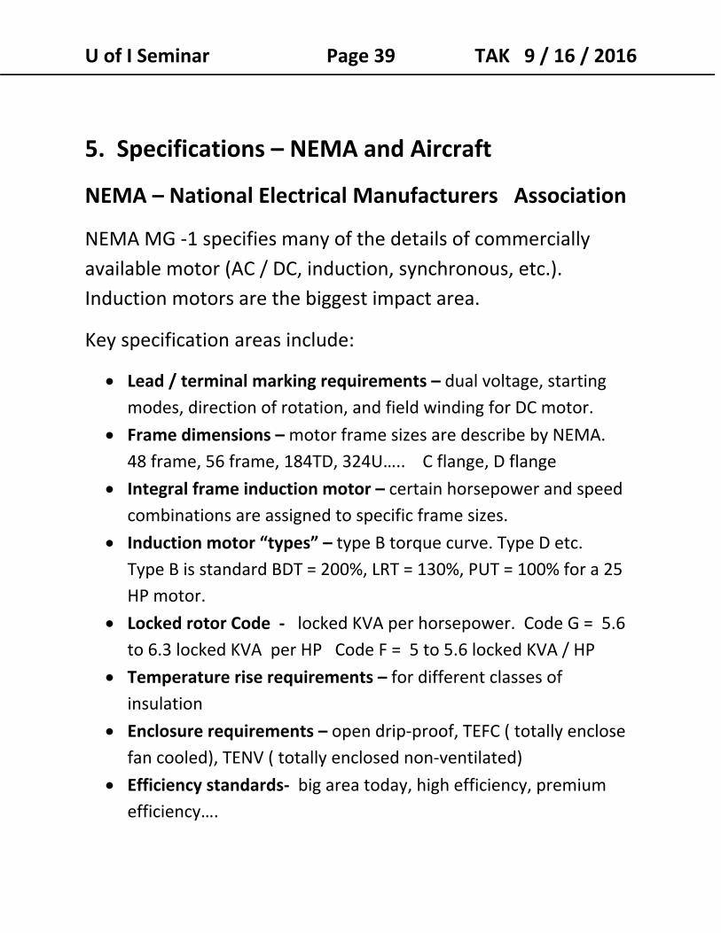
5. Specifications – NEMA and Aircraft
NEMA – National Electrical Manufacturers Association
NEMA MG ‐1 specifies many of the details of commercially
available motor (AC / DC, induction, synchronous, etc.).
Induction motors are the biggest impact area.
Key specification areas include:
Lead / terminal marking requirements – dual voltage, starting
modes, direction of rotation, and field winding for DC motor.
Frame dimensions – motor frame sizes are describe by NEMA.
48 frame, 56 frame, 184TD, 324U….. C flange, D flange
Integral frame induction motor – certain horsepower and speed
combinations are assigned to specific frame sizes.
Induction motor “types” – type B torque curve. Type D etc.
Type B is standard BDT = 200%, LRT = 130%, PUT = 100% for a 25
HP motor.
Locked rotor Code ‐ locked KVA per horsepower. Code G = 5.6 to 6.3 locked KVA per HP Code F = 5 to 5.6 locked KVA / HP
Temperature rise requirements – for different classes of
insulation
Enclosure requirements – open drip‐proof, TEFC ( totally enclose
fan cooled), TENV ( totally enclosed non‐ventilated)
Efficiency standards‐ big area today, high efficiency, premium
efficiency….
U of I Seminar Page 40 TAK 9 / 16 / 2016
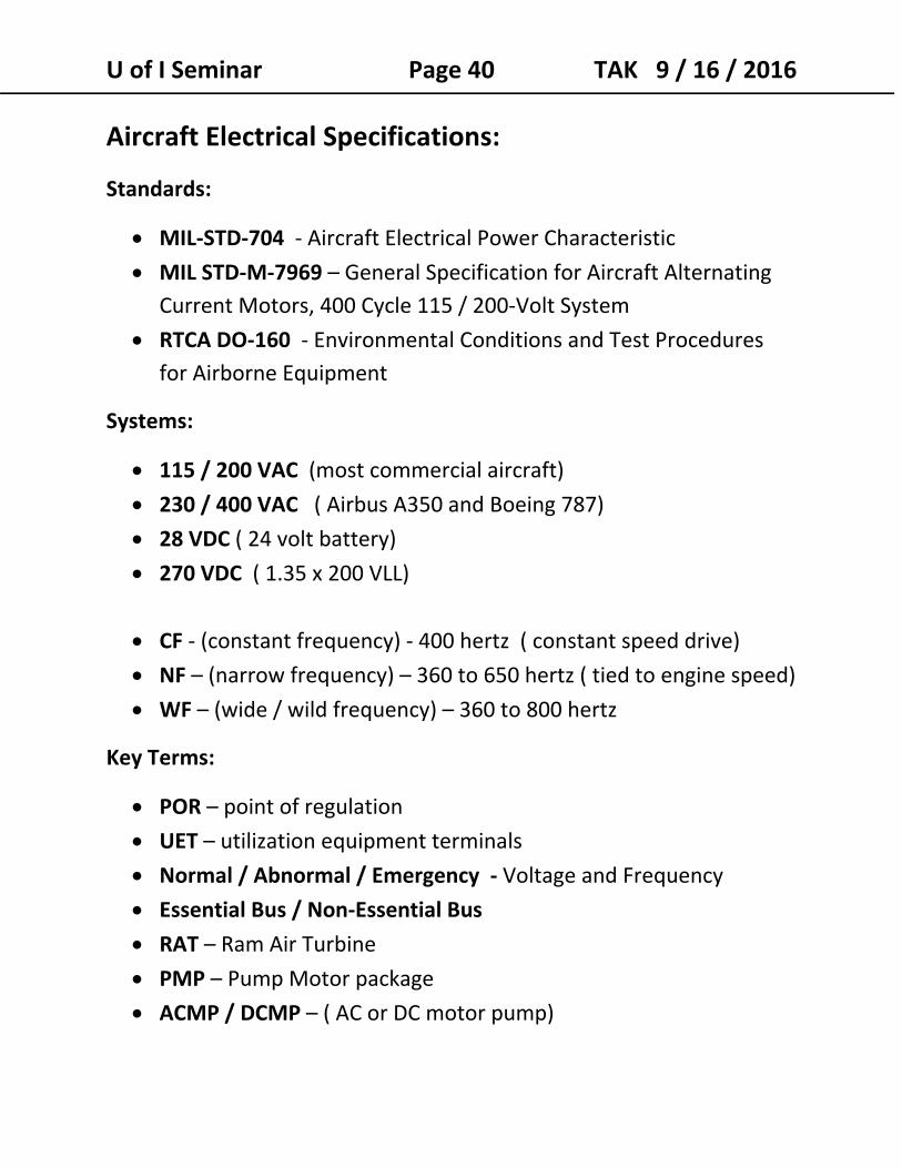
Aircraft Electrical Specifications:
Standards:
MIL‐STD‐704 ‐ Aircraft Electrical Power Characteristic
MIL STD‐M‐7969 – General Specification for Aircraft Alternating
Current Motors, 400 Cycle 115 / 200‐Volt System
RTCA DO‐160 ‐ Environmental Conditions and Test Procedures
for Airborne Equipment
Systems:
115 / 200 VAC (most commercial aircraft)
230 / 400 VAC ( Airbus A350 and Boeing 787) 28 VDC ( 24 volt battery) 270 VDC ( 1.35 x 200 VLL)
CF ‐ (constant frequency) ‐ 400 hertz ( constant speed drive) NF – (narrow frequency) – 360 to 650 hertz ( tied to engine speed) WF – (wide / wild frequency) – 360 to 800 hertz
Key Terms:
POR – point of regulation UET – utilization equipment terminals
Normal / Abnormal / Emergency ‐ Voltage and Frequency
Essential Bus / Non‐Essential Bus RAT – Ram Air Turbine
PMP – Pump Motor package
ACMP / DCMP – ( AC or DC motor pump)
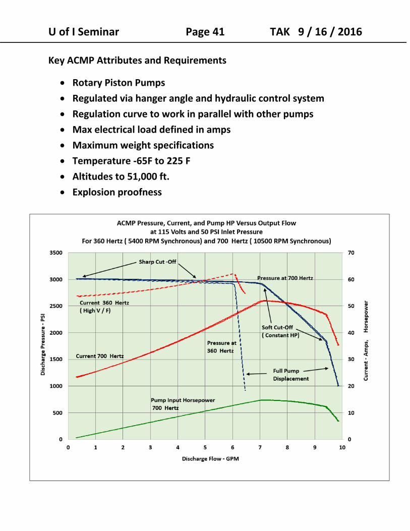
U of I Seminar Page 41 TAK 9 / 16 / 2016 Key ACMP Attributes and Requirements
Rotary Piston Pumps
Regulated via hanger angle and hydraulic control system
Regulation curve to work in parallel with other pumps
Max electrical load defined in amps
Maximum weight specifications
Temperature ‐65F to 225 F
Altitudes to 51,000 ft. Explosion proofness