Embed Size (px)
Citation preview
LS--20 100HP (75KW)
Part Number 02250075--727eSullair Corporation
AIR COMPRESSORINDUSTRIAL
STANDARD AND 24KT
OPERATOR’SMANUAL ANDPARTS LIST
KEEP FORFUTURE
REFERENCE
AIR CARESEMINAR TRAINING
Sullair Air Care Seminars are 3--day courses that provide hands--on instructionin the proper operation, maintenance and service of Sullair equipment.Individual seminars on Industrial compressors and compressor electricalsystems are presented at regular intervals throughout the year at a dedicatedtraining facility at Sullair’s corporate headquarters in Michigan City, Indiana.
Instruction includes discussion of the function and installation of Sullair serviceparts, troubleshooting of the most common problems, and actual equipmentoperation. The seminars are recommended for maintenance and servicepersonnel.
For detailed course outlines, schedule and cost information contact:
Sullair Corporate Training Department1--888--SULLAIR or 219--879--5451 (ext. 5363)
-- Or Write --Sullair Corporation3700 E. Michigan Blvd.Michigan City, IN 46360Attn: Service Training Department
TABLE OF CONTENTS
Section 1 Page
SAFETY 1 1.1 GENERAL
1 1.2 PERSONAL PROTECTIVE EQUIPMENT
1 1.3 PRESSURE RELEASE
2 1.4 FIRE AND EXPLOSION
2 1.5 MOVING PARTS
2 1.6 HOT SURFACES, SHARP EDGES AND SHARP CORNERS
2 1.7 TOXIC AND IRRITATING SUBSTANCES
3 1.8 ELECTRICAL SHOCK
3 1.9 LIFTING
4 1.10 ENTRAPMENT
Section 2INSTALLATION 5 2.1 MOUNTING OF COMPRESSOR PACKAGE
5 2.2 VENTILATION AND COOLING
5 2.3 SERVICE AIR PIPING
5 2.4 SHAFT COUPLING CHECK
5 2.5 FLUID LEVEL CHECK
6 2.6 MOTOR ROTATION CHECK
6 2.7 ELECTRICAL PREPARATION
Section 3SPECIFICATIONS 7 3.1 TABLE OF SPECIFICATIONS
8 3.2 LUBRICATION GUIDE -- STANDARD COMPRESSORS
8 3.3 LUBRICATION GUIDE -- 24KT COMPRESSORS
8 3.4 LUBRICATION GUIDE--OPTIONAL FLUID
Section 4SUPERVISOR IIDESCRIPTION 9 4.1 BASIC INTRODUCTION
9 4.2 KEYPAD -- ALL MODELS
9 4.3 STATUS DISPLAYS
10 4.4 LAMP INDICATORS-- ALL MODELS
Section 5COMPRESSORSYSTEMS 13 5.1 INTRODUCTION
13 5.2 DESCRIPTION OF COMPONENTS
14 5.3 SULLAIR COMPRESSOR UNIT,FUNCTIONAL DESCRIPTION
14 5.4 COMPRESSOR COOLING AND LUBRICATIONSYSTEM, FUNCTIONAL DESCRIPTION
TABLE OF CONTENTS(CONTINUED)
Section 5COMPRESSOR Page
SYSTEMS (cont.) 14 5.5 COMPRESSOR DISCHARGE SYSTEM,FUNCTIONAL DESCRIPTION
17 5.6 CONTROL SYSTEM, FUNCTIONAL DESCRIPTION
22 5.7 AIR INLET SYSTEM, FUNCTIONAL DESCRIPTION
Section 6COMPRESSOROPERATION 23 6.1 INTRODUCTION
23 6.2 PURPOSE OF CONTROLS
24 6.3 SUPERVISOR II OPERATING PARAMETERS -- SETUP
25 6.4 DELUXE PARAMETER SETUP
25 6.5 OPERATING THE COMPRESSOR
26 6.6 PURPOSE OF CONTROLS
26 6.7 SUPERVISOR II OUTPUT RELAYS
27 6.8 MOTOR ROTATION CHECK
27 6.9 INITIAL SHUTDOWN PROCEDURE
27 6.10 SUBSEQUENT START--UP PROCEDURE
27 6.11 SHUTDOWN PROCEDURE
Section 7MAINTENANCE 29 7.1 GENERAL
29 7.2 DAILY OPERATION
29 7.3 MAINTENANCE AFTER INITIAL 50 HOURSOF OPERATION
29 7.4 MAINTENANCE EVERY 1000 HOURS OF OPERATION
29 7.5 PARTS REPLACEMENT AND ADJUSTMENTPROCEDURES
29 AIR FILTER MAINTENANCE
30 FLUID FILTER MAINTENANCE
30 SEPARATOR ELEMENT MAINTENANCE
31 SHAFT COUPLING MAINTENANCE
Section 8TROUBLESHOOTING 33 8.1 INTRODUCTION
33 8.2 TROUBLESHOOTING
34 8.3 CALIBRATION
TABLE OF CONTENTS(CONTINUED)
Section 9 Page
PARTS LIST 35 9.1 PROCEDURE FOR ORDERING PARTS
35 9.2 RECOMMENDED SPARE PARTS LIST
38 9.3 FRAME, MOTOR, COMPRESSOR AND PARTS
40 9.4 AIR INLET ASSEMBLY
42 9.5 COMPRESSOR LUBRICATION SYSTEM (AIR--COOLED)
46 9.6 COMPRESSOR LUBRICATION SYSTEM WITHSPIRAL VALVE (AIR--COOLED)
50 9.7 COMPRESSOR LUBRICATION SYSTEM (WATER--COOLED)
54 9.8 COMPRESSOR LUBRICATION SYSTEM WITHSPIRAL VALVE (WATER--COOLED)
58 9.9 COMPRESSOR COOLER ASSEMBLY (AIR--COOLED)
60 9.10 COMPRESSOR WATER SYSTEM (WATER--COOLED)
62 9.11 COMPRESSOR DISCHARGE SYSTEM (AIR--COOLED)
68 9.12 COMPRESSOR DISCHARGE SYSTEM (WATER--COOLED)
74 9.13 CONTROLS
76 9.14 ELECTRICAL CONTROL SYSTEM (AIR--COOLED)
80 9.15 ELECTRICAL CONTROL SYSTEM (WATER--COOLED)
84 9.16 UNIT TUBING
86 9.17 MOTOR ASSEMBLY
88 9.18 ENCLOSURE ASSEMBLY (AIR--COOLED)
92 9.19 ENCLOSURE ASSEMBLY (WATER--COOLED)
96 9.20 DECAL GROUP
104 9.21 WIRING DIAGRAM LS--20 STANDARD
105 9.22 WIRING DIAGRAM WYE--DELTA STANDARD
106 9.23 WIRING DIAGRAM DELUXE STANDARD
107 9.24 WIRING DIAGRAM WYE--DELTA DELUXE

NOTES

Section 1SAFETY
1.1 GENERALSullair Corporation and its subsidiaries design andmanufacture all of their products so they can be op-erated safely. However, the responsibility for safeoperation rests with those who use and maintainthese products. The following safety precautionsare offered as a guide which, if conscientiously fol-lowed, will minimize the possibility of accidentsthroughout the useful life of this equipment.
The compressor should be operated only by thosewho have been trained and delegated to do so, andwho have read and understood this Operator’sManual. Failure to follow the instructions, proce-dures and safety precautions in this manual can re-sult in accidents and injuries. Read thismanualpriorto startup.
NEVER start the compressor unless it is safe to doso.DONOT attempt to operate the compressorwitha known unsafe condition. Tag the compressor andrender it inoperative by disconnecting and lockingout all power at source or otherwise disabling itsprimemover, so otherswhomaynot knowof the un-safe condition, cannot attempt to operate it until thecondition is corrected.
Install, use and operate the compressor only in fullcompliance with all pertinent regulations and all ap-plicable Federal, State, and Local codes, standardsand regulations.
DO NOT modify the compressor and/or controls inany way except with written factory approval.
While not specifically applicable to all types of com-pressors with all types of prime movers, most of theprecautionary statements contained herein are ap-plicable to most compressors and the concepts be-hind these statements are generally applicable to allcompressors.
1.2 PERSONAL PROTECTIVE EQUIPMENTPrior to installing or operating the compressor, own-ers, employers and users should become familiarwith, and comply with, all applicable regulations andany applicable Federal, State and Local codes,standards, and regulations relative to personal pro-tective equipment, such as eye and face protectiveequipment, respiratory protective equipment,equipment intended to protect the extremities, pro-tective clothing, protective shields and barriers andelectrical protective equipment, as well as noise ex-posure administrative and/or engineering controlsand/or personal hearing protective equipment.
1.3 PRESSURE RELEASEA. Install an appropriate flow--limiting valve betweenthe service air outlet and the shut--off (throttle)valve, either at the compressor or at any other pointalong the air line, when an air hose exceeding 1/2”(13mm) inside diameter is to be connected to theshut--off (throttle) valve, to reduce pressure in case
of hose failure, per all applicable Federal, State andLocal codes, standards and regulations.
B.When thehose is to beused to supply amanifold,install an additional appropriate flow--limiting valvebetween the manifold and each air hose exceeding1/2” (13mm) inside diameter that is to be connectedto the manifold to reduce pressure in case of hosefailure.
C. Provide an appropriate flow--limiting valve at thebeginningof eachadditional 75 feet (23m) of hose inruns of air hoseexceeding 1/2” (13mm) insidediam-eter to reduce pressure in case of hose failure.
D. Flow--limiting valves are listed by pipe size andrated CFM. Select appropriate valves accordingly,in accordancewith their manufacturer’s recommen-dations.
E. DO NOT use air tools that are rated below themaximum rating of the compressor. Select air tools,air hoses, pipes, valves, filters, and other fittings ac-cordingly. DO NOT exceed manufacturer’s ratedsafe operating pressures for these items.
F.Secure all hose connections by wire, chain or oth-er suitable retaining devices to prevent tools or hoseends from being accidentally disconnected and ex-pelled.
G.Open fluid filler cap only whencompressor is notrunning and is not pressurized. Shut down thecompressor and bleed the sump (receiver) to zerointernal pressure before removing the cap.
H. Vent all internal pressure prior to opening anyline, fitting, hose, valve, drain plug, connection orother component, such as filters and line oilers, andbefore attempting to refill optional air line anti--icersystems with antifreeze compound.
I. Keep personnel out of line with and away from thedischarge opening of hoses or tools or other pointsof compressed air discharge.
J.Use air at pressures less than30 psig (2.1 bar) forcleaning purposes, and then only with effective chipguarding and personal protective equipment.
K. DO NOT engage in horseplay with air hoses asdeath or serious injury may result.
L. DONOT tamper with sump and unit (if provided)relief valves. Check the relief valve as recom-mended in the Maintenance Section of this manualor at a minimum of at least weekly to make sure it isnot blocked, clogged, obstructed or otherwise dis-abled. DONOT change the factory setting of the re-lief valve.
M. If the compressor is installed in an enclosedarea, it is necessary to vent the relief valve to theoutside of the structure or to an area of non--expo-sure.
1
Section 1SAFETY
2
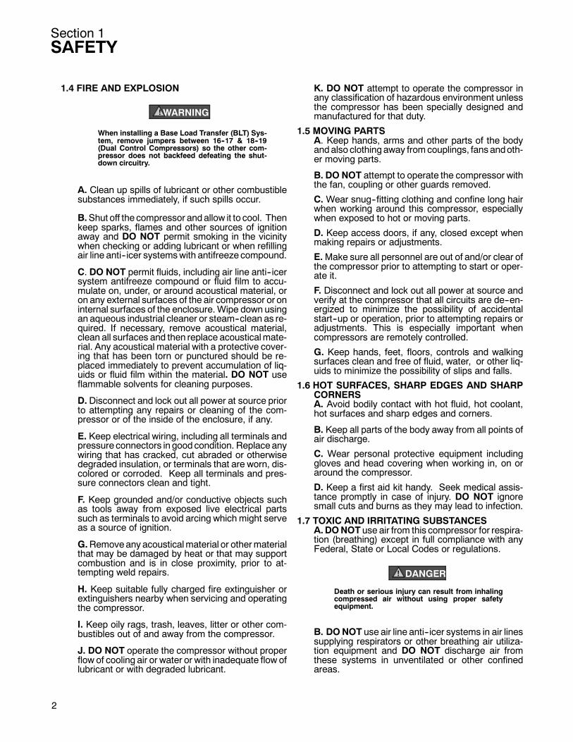
1.4 FIRE AND EXPLOSION
WARNING!
When installing a Base Load Transfer (BLT) Sys-tem, remove jumpers between 16--17 & 18--19(Dual Control Compressors) so the other com-pressor does not backfeed defeating the shut-down circuitry.
A. Clean up spills of lubricant or other combustiblesubstances immediately, if such spills occur.
B.Shut off the compressor andallow it to cool. Thenkeep sparks, flames and other sources of ignitionaway and DO NOT permit smoking in the vicinitywhen checking or adding lubricant or when refillingair line anti--icer systemswith antifreeze compound.
C. DO NOT permit fluids, including air line anti--icersystem antifreeze compound or fluid film to accu-mulate on, under, or around acoustical material, oron any external surfaces of the air compressor or oninternal surfaces of the enclosure.Wipe down usingan aqueous industrial cleaner or steam--clean as re-quired. If necessary, remove acoustical material,clean all surfaces and then replace acousticalmate-rial. Any acoustical material with a protective cover-ing that has been torn or punctured should be re-placed immediately to prevent accumulation of liq-uids or fluid film within the material. DO NOT useflammable solvents for cleaning purposes.
D. Disconnect and lock out all power at source priorto attempting any repairs or cleaning of the com-pressor or of the inside of the enclosure, if any.
E. Keep electrical wiring, including all terminals andpressure connectors in good condition. Replaceanywiring that has cracked, cut abraded or otherwisedegraded insulation, or terminals that are worn, dis-colored or corroded. Keep all terminals and pres-sure connectors clean and tight.
F. Keep grounded and/or conductive objects suchas tools away from exposed live electrical partssuch as terminals to avoid arcing which might serveas a source of ignition.
G.Removeany acousticalmaterial or othermaterialthat may be damaged by heat or that may supportcombustion and is in close proximity, prior to at-tempting weld repairs.
H. Keep suitable fully charged fire extinguisher orextinguishers nearby when servicing and operatingthe compressor.
I. Keep oily rags, trash, leaves, litter or other com-bustibles out of and away from the compressor.
J. DO NOT operate the compressor without properflow of cooling air or water or with inadequate flow oflubricant or with degraded lubricant.
K. DO NOT attempt to operate the compressor inany classification of hazardous environment unlessthe compressor has been specially designed andmanufactured for that duty.
1.5 MOVING PARTSA. Keep hands, arms and other parts of the bodyandalso clothingaway fromcouplings, fans andoth-er moving parts.
B. DO NOT attempt to operate the compressor withthe fan, coupling or other guards removed.
C. Wear snug--fitting clothing and confine long hairwhen working around this compressor, especiallywhen exposed to hot or moving parts.
D. Keep access doors, if any, closed except whenmaking repairs or adjustments.
E.Make sure all personnel are out of and/or clear ofthe compressor prior to attempting to start or oper-ate it.
F. Disconnect and lock out all power at source andverify at the compressor that all circuits are de--en-ergized to minimize the possibility of accidentalstart--up or operation, prior to attempting repairs oradjustments. This is especially important whencompressors are remotely controlled.
G. Keep hands, feet, floors, controls and walkingsurfaces clean and free of fluid, water, or other liq-uids to minimize the possibility of slips and falls.
1.6 HOT SURFACES, SHARP EDGES AND SHARPCORNERSA. Avoid bodily contact with hot fluid, hot coolant,hot surfaces and sharp edges and corners.
B. Keep all parts of the body away from all points ofair discharge.
C. Wear personal protective equipment includinggloves and head covering when working in, on oraround the compressor.
D. Keep a first aid kit handy. Seek medical assis-tance promptly in case of injury. DO NOT ignoresmall cuts and burns as they may lead to infection.
1.7 TOXIC AND IRRITATING SUBSTANCESA.DONOT use air from this compressor for respira-tion (breathing) except in full compliance with anyFederal, State or Local Codes or regulations.
DANGER!
Death or serious injury can result from inhalingcompressed air without using proper safetyequipment.
B. DONOT use air line anti--icer systems in air linessupplying respirators or other breathing air utiliza-tion equipment and DO NOT discharge air fromthese systems in unventilated or other confinedareas.

Section 1SAFETY
C. Operate the compressor only in open or ade-quately ventilated areas.
D. Locate the compressor or provide a remote inletso that it is not likely to ingest exhaust fumes or othertoxic, noxious or corrosive fumes or substances.
E. Coolants and lubricants used in this compressorare typical of the industry. Care should be taken toavoid accidental ingestion and/or skin contact. Inthe event of ingestion, seek medical treatmentpromptly. Wash with soap and water in the event ofskin contact. Consult the compressor operator’smanual lubrication section for informationpertainingto compressor fluid fill.
F.Wear goggles or a full face shieldwhenaddingan-tifreeze compound to air line anti--icer systems.
G. If air line anti--icer system antifreeze compoundenters the eyes or if fumes irritate the eyes, theyshould be washed with large quantities of clean wa-ter for 15 minutes. A physician, preferably an eyespecialist, should be contacted immediately.
H. DONOT store air line anti--icer systemantifreezecompound in confined areas.
I. The antifreeze compound used in air line anti-freeze systems contains methanol and is toxic,harmful, or fatal if swallowed. Avoid contact with theskin or eyes and avoid breathing the fumes. If swal-lowed, induce vomiting by administering a table-spoon of salt, in each glass of clean, warmwater un-til vomit is clear, then administer two teaspoons ofbaking soda in a glass of clean water. Have patientlay down and cover eyes to exclude light. Call a phy-sician immediately.
1.8 ELECTRICAL SHOCKA. This compressor should be installed and main-tained in full compliance with all applicable Federal,State and Local codes, standards and regulations,including those of the National Electrical Code, andalso including those relative to equipment groundingconductors, and only by personnel that are trained,qualified and delegated to do so.
B. Keep all parts of the body and any hand--heldtools or other conductive objects away from ex-posed live parts of electrical system. Maintain dryfooting, stand on insulating surfaces and DO NOTcontact any other portion of the compressor whenmaking adjustments or repairs to exposed live partsof the electrical system. Make all such adjustmentsor repairs with one hand only, so as to minimize thepossibility of creating a current path through theheart.
C. Attempt repairs in clean, dry and well lighted andventilated areas only.
D. DO NOT leave the compressor unattended withopen electrical enclosures. If necessary to do so,thendisconnect, lock out and tag all power at sourceso others will not inadvertently restore power.
E. Disconnect, lock out, and tag all power at sourceprior to attempting repairs or adjustments to rotatingmachinery and prior to handling any ungroundedconductors.F. Dry test all shutdown circuits prior to starting thecompressor after installation.
1.9 LIFTINGA. If the compressor is provided with a lifting bail,then lift by the bail provided. If no bail is provided,then lift by sling. Compressors to be air lifted by heli-coptermust not be supportedby the lifting bail but byslings instead. In any event, lift and/or handle only infull compliancewithFederal, State and Local codes.
B. Inspect points of attachment for cracked weldsand for cracked, bent, corroded or otherwise de-graded members and for loose bolts or nuts prior tolifting.C. Make sure entire lifting, rigging and supportingstructure has been inspected, is in good conditionand has a rated capacity of at least the weight of thecompressor. If you are unsure of the weight, thenweigh compressor before lifting.D. Make sure lifting hook has a functional safetylatch or equivalent, and is fully engaged and latchedon the bail or slings.E. Use guide ropes or equivalent to prevent twistingor swingingof the compressor once it has been liftedclear of the ground.F. DO NOT attempt to lift in high winds.G.Keep all personnel out from under and away fromthe compressor whenever it is suspended.H. Lift compressor no higher than necessary.I.Keep lift operator in constant attendancewhenev-er compressor is suspended.J. Set compressor down only on a level surface ca-pable of safely supporting at least its weight and itsloading unit.K. When moving compressors by forklift truck, uti-lize fork pockets if provided. Otherwise, utilize palletif provided. If neither fork pockets or pallet are pro-vided, then make sure compressor is secure andwell balanced on forks before attempting to raise ortransport it any significant distance.L. Make sure forklift truck forks are fully engagedand tipped back prior to lifting or transporting thecompressor.M. Forklift no higher than necessary to clear ob-stacles at floor level and transport and corner atminimum practical speeds.N. Make sure pallet--mounted compressors arefirmly bolted or otherwise secured to the pallet priorto attempting to forklift or transport them. NEVERattempt to forklift a compressor that isnot secured toits pallet, as uneven floors or sudden stops maycause the compressor to tumble off, possibly caus-ing serious injury or property damage in theprocess.
3
Section 1SAFETY
O. DO NOT use the lifting eye bolt on the compres-sor motor, if supplied, to lift the entire compressorpackage.
1.10 ENTRAPMENTA. If the compressor enclosure is large enough tohold a person and if it is necessary to enter it to per-form service adjustments, inform other personnel
4
before doing so, or else secure and tag the accessdoor in the open position to avoid the possibility ofothers closing and possibly latching the door withpersonnel inside.
B. Make sure all personnel are out of compressorbefore closing and latching enclosure doors.
Section 2INSTALLATION
2.1 MOUNTING OF COMPRESSOR PACKAGEThe compressor package should be placed over asurface or foundation that is capable of supportingits weight, while remaining level and free of deflec-tionswhichmayaffect thedrivelinemounts or the in-board pipework.It is recommended that the package frame be lev-eled and secured to the foundation with adequateanchorage, and that a good grade grouting be usedto insure full contact between the load bearing sur-faces.The compressor/motor driveline is self--aligned bythe use of a rigid distance piece and supported byflexible vibration isolation mounts. Poor leveling orexcessive deflections may adversely affect the op-eration and longevity of these devices.No piping loads should be transmitted to the air andwater connections provided with the package.
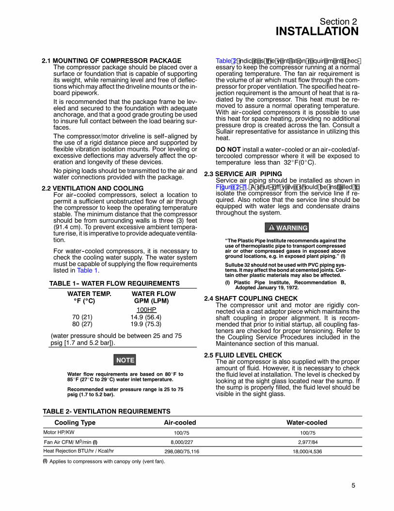
2.2 VENTILATION AND COOLINGFor air--cooled compressors, select a location topermit a sufficient unobstructed flow of air throughthe compressor to keep the operating temperaturestable. The minimum distance that the compressorshould be from surrounding walls is three (3) feet(91.4 cm). To prevent excessive ambient tempera-ture rise, it is imperative to provide adequate ventila-tion.
For water--cooled compressors, it is necessary tocheck the cooling water supply. The water systemmust be capable of supplying the flow requirementslisted in Table 1.
NOTE
Water flow requirements are based on 80_F to85_F (27_C to 29_C) water inlet temperature.
Recommended water pressure range is 25 to 75psig (1.7 to 5.2 bar).
Table 2 indic at es t he v ent ilat ion r equir em ent s nec -essary to keep the compressor running at a normaloperating temperature. The fan air requirement isthe volume of air which must flow through the com-pressor for proper ventilation. The specified heat re-jection requirement is the amount of heat that is ra-diated by the compressor. This heat must be re-moved to assure a normal operating temperature.With air--cooled compressors it is possible to usethis heat for space heating, providing no additionalpressure drop is created across the fan. Consult aSullair representative for assistance in utilizing thisheat.
DO NOT install a water--cooled or an air--cooled/af-tercooled compressor where it will be exposed totemperature less than 32_F(0_C).
2.3 SERVICE AIR PIPINGService air piping should be installed as shown inF igur e 2 -- 1. A s hut -- off v alv e s hould be ins t alled t oisolate the compressor from the service line if re-quired. Also notice that the service line should beequipped with water legs and condensate drainsthroughout the system.
WARNING!
“ThePlastic Pipe Institute recommends against theuse of thermoplastic pipe to transport compressedair or other compressed gases in exposed aboveground locations, e.g. in exposed plant piping.” (I)
Sullube 32 should not beused with PVC piping sys-tems. Itmay affect thebond atcemented joints.Cer-tain other plastic materials may also be affected.(I) Plastic Pipe Institute, Recommendation B,
Adopted January 19, 1972.
2.4 SHAFT COUPLING CHECKThe compressor unit and motor are rigidly con-nected via a cast adaptor piecewhich maintains theshaft coupling in proper alignment. It is recom-mended that prior to initial startup, all coupling fas-teners are checked for proper tensioning. Refer tothe Coupling Service Procedures included in theMaintenance section of this manual.
2.5 FLUID LEVEL CHECKThe air compressor is also supplied with the properamount of fluid. However, it is necessary to checkthe fluid level at installation. The level is checked bylooking at the sight glass located near the sump. Ifthe sump is properly filled, the fluid level should bevisible in the sight glass.
WATER TEMP. WATER FLOW____F (____C) GPM (LPM)
100HP70 (21)80 (27)
(water pressure should be between 25 and 75psig [1.7 and 5.2 bar]).
14.9 (56.4)19.9 (75.3)
TABLE 1-- WATER FLOW REQUIREMENTS
Cooling Type Air-cooled Water-cooledMotor HP/KW
Heat Rejection BTU/hr / Kcal/hr
Applies to compressors with canopy only (vent fan).(I)
100/75
8,000/227
298,080/75,116
100/75
2,977/84
18,000/4,536
Fan Air CFM/ M3/min (I)
TABLE 2- VENTILATION REQUIREMENTS
5

Section 2INSTALLATION
6
2.6 MOTOR ROTATION CHECKAfter the electrical installation has been done, it isnecessary to check the direction of motor rotation.Pull out the EMERGENCY STOP button and pressonce, quickly and in succession, the (START) “I”and (STOP) “O” pads. This action will “bump start”the motor for a very short time. When looking at themotor rear end, the driveline should be rotatingcounterclockwise. If the reversed rotation is noted,disconnect the power to the starter and exchangeany two of the three power input leads, then re--check rotation. A “Direction of Rotation” decal is lo-cated on the top of the compressor/motor adaptorpiece.
2.7 ELECTRICAL PREPARATIONInterior electrical wiring is performed at the factory.Required customer wiring is minimal, but should bedone by a qualified electrician in compliance withOSHA, National Electrical Code, and/or any otherapplicable local electrical codes concerning isola-tion switches, fuse disconnects, etc. Sullair pro-vides a wiring diagram for use by the installer.
A few electrical checks should be made to help as-sure that the first start--up will be trouble free.
DANGER!
Lethal shock hazard inside.Disconnect all power at sourcebefore opening orservicing.
NOTE
Customer must provide electrical supply powerdisconnect within sight of machine.
1. Check incoming voltage. Be sure that the incom-ing voltage is the same voltage that the compres-sor was wired for.
2. Check starter and overload heater sizes (seeelectrical parts in Parts Manual).
3. Check all electrical connections for tightness.4. “DRY RUN” the electrical controls by disconnect-
ing the three (3) motor leads from the starter. En-ergize the control circuits by pushing the(START) “I” pad and checking all protective de-vices to be sure that they will de--energize thestarter coil when activated.
5. Reconnect the three (3) motor leads and jog themotor for a direction of rotation check, as ex-plained in S ec t ion 2. 6.
Figure 2-1 Service Air Piping (Typical Installation)
Section 3SPECIFICATIONS
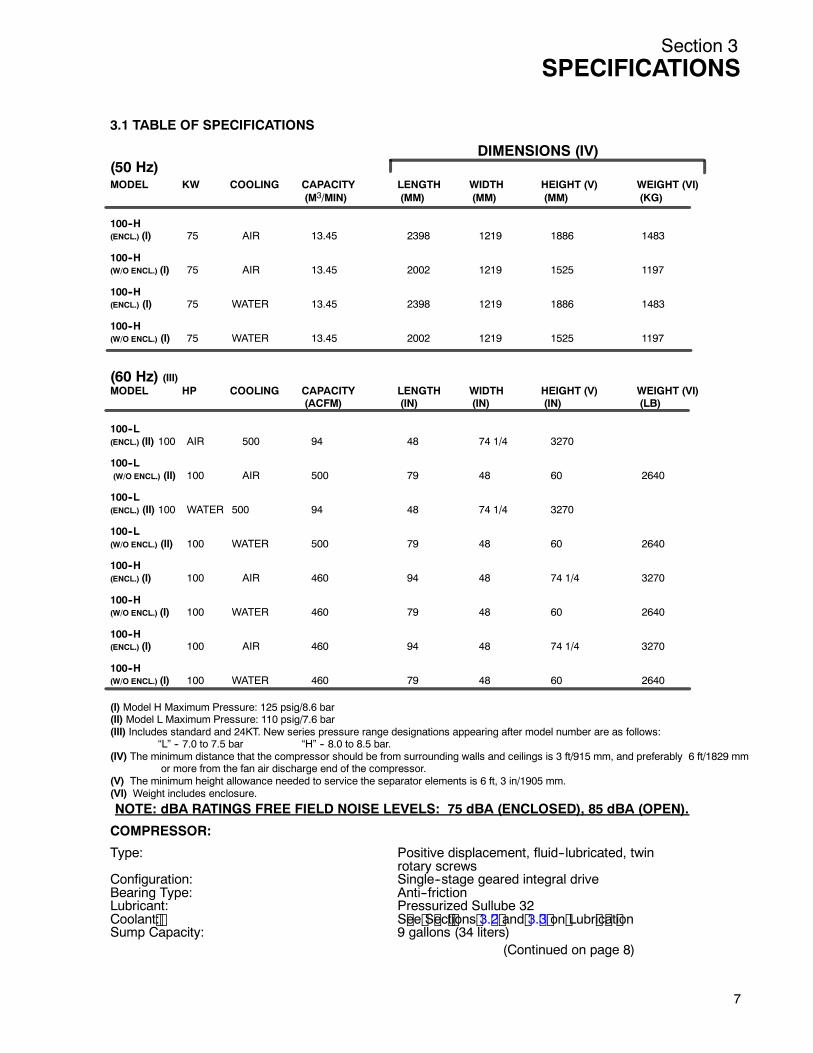
3.1 TABLE OF SPECIFICATIONS
DIMENSIONS (IV)(50 Hz)MODEL KW COOLING CAPACITY LENGTH WIDTH HEIGHT (V) WEIGHT (VI)
(M3/MIN) (MM) (MM) (MM) (KG)
100--H(ENCL.) (I) 75 AIR 13.45 2398 1219 1886 1483
100--H(W/O ENCL.) (I) 75 AIR 13.45 2002 1219 1525 1197
100--H(ENCL.) (I) 75 WATER 13.45 2398 1219 1886 1483
100--H(W/O ENCL.) (I) 75 WATER 13.45 2002 1219 1525 1197
(60 Hz) (III)MODEL HP COOLING CAPACITY LENGTH WIDTH HEIGHT (V) WEIGHT (VI)
(ACFM) (IN) (IN) (IN) (LB)
100--L(ENCL.) (II) 100 AIR 500 94 48 74 1/4 3270
100--L(W/O ENCL.) (II) 100 AIR 500 79 48 60 2640
100--L(ENCL.) (II) 100 WATER 500 94 48 74 1/4 3270
100--L(W/O ENCL.) (II) 100 WATER 500 79 48 60 2640
100--H(ENCL.) (I) 100 AIR 460 94 48 74 1/4 3270
100--H(W/O ENCL.) (I) 100 WATER 460 79 48 60 2640
100--H(ENCL.) (I) 100 AIR 460 94 48 74 1/4 3270
100--H(W/O ENCL.) (I) 100 WATER 460 79 48 60 2640
(I) Model H Maximum Pressure: 125 psig/8.6 bar(II) Model L Maximum Pressure: 110 psig/7.6 bar(III) Includes standard and 24KT. New series pressure range designations appearing after model number are as follows:
“L” -- 7.0 to 7.5 bar “H” -- 8.0 to 8.5 bar.(IV) The minimum distance that the compressor should be from surrounding walls and ceilings is 3 ft/915 mm, and preferably 6 ft/1829 mm
or more from the fan air discharge end of the compressor.(V) The minimum height allowance needed to service the separator elements is 6 ft, 3 in/1905 mm.(VI) Weight includes enclosure.
NOTE: dBA RATINGS FREE FIELD NOISE LEVELS: 75 dBA (ENCLOSED), 85 dBA (OPEN).
COMPRESSOR:
Type: Positive displacement, fluid--lubricated, twinrotary screws
Configuration: Single--stage geared integral driveBearing Type: Anti--frictionLubricant: Pressurized Sullube 32Coolant : S ee S ec t ions 3. 2 and 3. 3 on Lubr ic at ionSump Capacity: 9 gallons (34 liters)
(Continued on page 8)
7

Section 3SPECIFICATIONS
8
Duty Press: 100--110 psig (6.9--7.6 bar)Control Type: Electro--pneumaticOptions: Higher duty pressures up to 175 psig (12.1 bar),
spiral valve, 24KT lubricant
50 Hz MOTOR:Size: 100 HP/ 75 KW, 4--pole speedService: 3 ph, 50 Hz, 400 VAC, 104_F/40_C ambientType: Frame: IP23, P250SP--P250MP, Mounting: IM1001 (Foot)Options: IP55 enclosure, various voltages
60 Hz MOTOR:Size: 100 HP, 4--pole speedService: 3 ph, 60 Hz, 460 VAC, 104_F/40_C ambient riseType: ODP enclosure, NEMA frame 404TSCOptions: TEFC enclosure, various voltages
3.2 LUBRICATION GUIDE--STANDARD COMPRES-SORSSullair standard compressors are filled with Sullube32 fluid as factory fill.
WARNING!
Mixing of other lubricantswithin the compressorunit will void all warranties!
Sullube 32 fluid should be changed every 8000hours or once a year, whichever comes first. Thefluid should be changed more frequently under se-vere operating conditions, such as high ambienttemperatures coupled with high humidity, or whenhigh particulate level, corrosive gases or strong oxi-dizing gases are present in the air.
WARNING!
“ThePlastic Pipe Institute recommends against theuse of thermoplastic pipe to transport compressedair or other compressed gases in exposed aboveground locations, e.g. in exposed plant piping.” (I)
Sullube 32 should not beused with PVC piping sys-tems. Itmay affect thebond atcemented joints.Cer-tain other plastic materials may also be affected.
(I) Plastic Pipe Institute, Recommendation B,Adopted January 19, 1972.
Maintenance of all other components is still recom-mended as indicated in the Operator’s Manual.
APPLICATION GUIDESullair encourages the user to participate in a fluidanalysis program with the fluid suppliers. This couldresult in a fluid change interval differing from thatstated in the manual. Contact your Sullair dealer fordetails.
3.3 LUBRICATION GUIDE--24KT COMPRESSORSSullair 24KT compressors are filled with a lubricantwhich rarely needs to be changed. In the event achange of fluid is required, use only Sullair 24KTfluid.
WARNING!
Mixing of other lubricantswithin the compressorunit will void all warranties!
Sullair recommends that a 24KT sample be taken atthe first filter change and sent to the factory for anal-ysis. This is a free service. A sample kit with instruc-tions and self--addressed container is to be suppliedby your Sullair Representative at start--up. The userwill receive an analysis report with recommenda-tions.
3.4 LUBRICATION GUIDE--OPTIONAL FLUIDSullair compressors may use SRF 1/4000 fluid asan optional factory fill.
WARNING!
Mixing of other fluids within the compressor willvoid all warranties!
SRF 1/4000 fluid should be changed every 4000hours or once a year, whichever comes first. Thefluid should be changed more frequently under se-vere operating conditions, such as high ambienttemperatures coupled with high humidity, or whenhigh particulate level, corrosive gases or strong oxi-dizing gases are present in the air.
For extended life synthetic lubricants contact thenearest Sullair representative.
Maintenance of all other components is still recom-mended as indicated in the Operator’s Manual.
Section 4SUPERVISOR II DESCRIPTION
4.1 BASIC INTRODUCTION
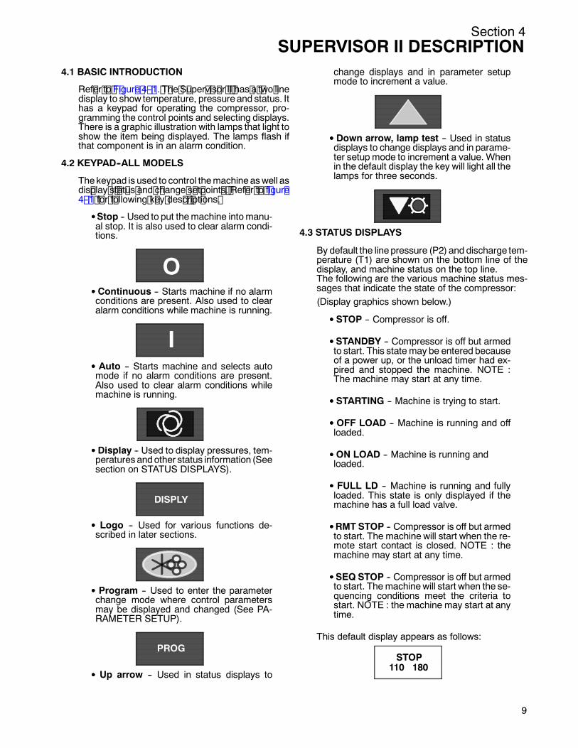
Ref er t o F igur e 4 -- 1. T he S uper v is or I I has a t wo linedisplay to show temperature, pressure and status. Ithas a keypad for operating the compressor, pro-gramming the control points and selecting displays.There is a graphic illustration with lamps that light toshow the item being displayed. The lamps flash ifthat component is in an alarm condition.
4.2 KEYPAD--ALL MODELS
Thekeypad is used to control themachineaswell asdis play s t at us and c hange s et point s . Ref er t o f igur e4 -- 1 f or f ollowing k ey des c r ipt ions .
SSSSStop -- Used to put themachine intomanu-al stop. It is also used to clear alarm condi-tions.
OSSSS Continuous -- Starts machine if no alarmconditions are present. Also used to clearalarm conditions while machine is running.
ISSSS Auto -- Starts machine and selects automode if no alarm conditions are present.Also used to clear alarm conditions whilemachine is running.
SSSS Display -- Used to display pressures, tem-peratures andother status information (Seesection on STATUS DISPLAYS).
DISPLY
SSSS Logo -- Used for various functions de-scribed in later sections.
SSSS Program -- Used to enter the parameterchange mode where control parametersmay be displayed and changed (See PA-RAMETER SETUP).
PROG
SSSS Up arrow -- Used in status displays to
change displays and in parameter setupmode to increment a value.
SSSS Down arrow, lamp test -- Used in statusdisplays to change displays and in parame-ter setup mode to increment a value. Whenin the default display the key will light all thelamps for three seconds.
4.3 STATUS DISPLAYS
By default the line pressure (P2) and discharge tem-perature (T1) are shown on the bottom line of thedisplay, and machine status on the top line.The following are the various machine status mes-sages that indicate the state of the compressor:(Display graphics shown below.)
SSSS STOP -- Compressor is off.
SSSS STANDBY -- Compressor is off but armedto start. This state may be entered becauseof a power up, or the unload timer had ex-pired and stopped the machine. NOTE :The machine may start at any time.
SSSS STARTING -- Machine is trying to start.
SSSS OFF LOAD -- Machine is running and offloaded.
SSSS ON LOAD -- Machine is running andloaded.
SSSS FULL LD -- Machine is running and fullyloaded. This state is only displayed if themachine has a full load valve.
SSSSRMT STOP -- Compressor is off but armedto start. The machine will start when the re-mote start contact is closed. NOTE : themachine may start at any time.
SSSS SEQ STOP -- Compressor is off but armedto start. The machinewill start when the se-quencing conditions meet the criteria tostart. NOTE : the machine may start at anytime.
This default display appears as follows:
STOP110 180
9
Section 4SUPERVISOR II DESCRIPTION
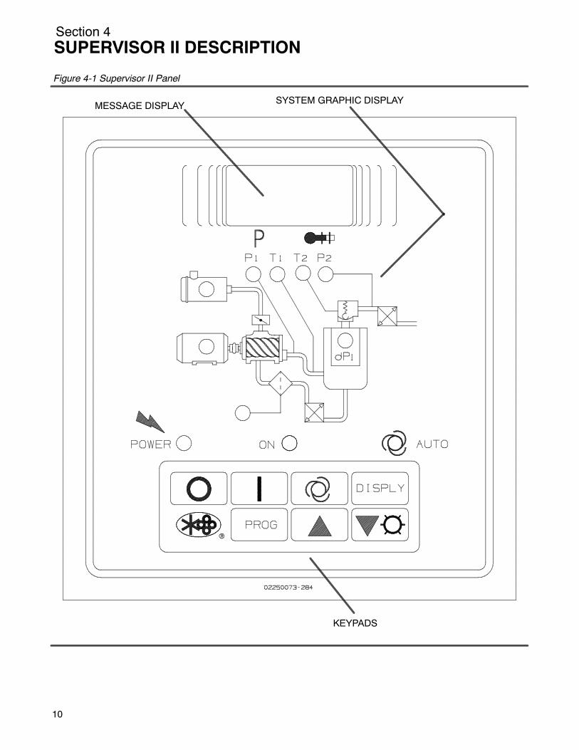
Figure 4-1 Supervisor II Panel
MESSAGE DISPLAY SYSTEM GRAPHIC DISPLAY
KEYPADS
10
Section 4SUPERVISOR II DESCRIPTION
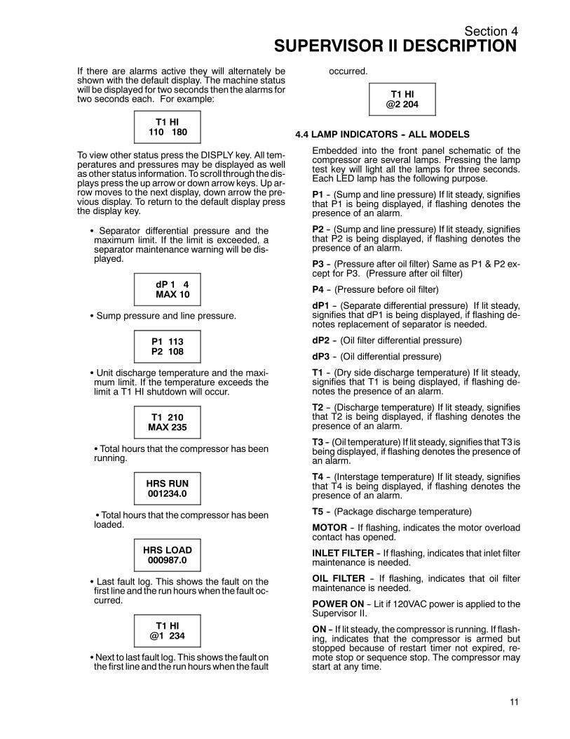
If there are alarms active they will alternately beshown with the default display. The machine statuswill be displayed for two seconds then the alarms fortwo seconds each. For example:
T1 HI110 180
To view other status press the DISPLY key. All tem-peratures and pressures may be displayed as wellas other status information. To scroll through thedis-plays press the up arrow or down arrow keys. Up ar-row moves to the next display, down arrow the pre-vious display. To return to the default display pressthe display key.
S Separator differential pressure and themaximum limit. If the limit is exceeded, aseparator maintenance warning will be dis-played.
dP 1 4MAX 10
S Sump pressure and line pressure.
P1 113P2 108
S Unit discharge temperature and the maxi-mum limit. If the temperature exceeds thelimit a T1 HI shutdown will occur.
T1 210MAX 235
S Total hours that the compressor has beenrunning.
HRS RUN001234.0
STotal hours that the compressor has beenloaded.
HRS LOAD000987.0
S Last fault log. This shows the fault on thefirst line and the runhourswhen the fault oc-curred.
T1 HI@1 234
SNext to last fault log. This shows the fault onthe first line and the runhourswhen the fault
occurred.
T1 HI@2 204
4.4 LAMP INDICATORS -- ALL MODELS
Embedded into the front panel schematic of thecompressor are several lamps. Pressing the lamptest key will light all the lamps for three seconds.Each LED lamp has the following purpose.
P1 -- (Sump and line pressure) If lit steady, signifiesthat P1 is being displayed, if flashing denotes thepresence of an alarm.
P2 -- (Sump and line pressure) If lit steady, signifiesthat P2 is being displayed, if flashing denotes thepresence of an alarm.
P3 -- (Pressure after oil filter) Same as P1 & P2 ex-cept for P3. (Pressure after oil filter)
P4 -- (Pressure before oil filter)
dP1 -- (Separate differential pressure) If lit steady,signifies that dP1 is being displayed, if flashing de-notes replacement of separator is needed.
dP2 -- (Oil filter differential pressure)
dP3 -- (Oil differential pressure)
T1 -- (Dry side discharge temperature) If lit steady,signifies that T1 is being displayed, if flashing de-notes the presence of an alarm.
T2 -- (Discharge temperature) If lit steady, signifiesthat T2 is being displayed, if flashing denotes thepresence of an alarm.
T3 -- (Oil temperature) If lit steady, signifies that T3 isbeing displayed, if flashing denotes the presence ofan alarm.
T4 -- (Interstage temperature) If lit steady, signifiesthat T4 is being displayed, if flashing denotes thepresence of an alarm.
T5 -- (Package discharge temperature)
MOTOR -- If flashing, indicates the motor overloadcontact has opened.
INLET FILTER -- If flashing, indicates that inlet filtermaintenance is needed.
OIL FILTER -- If flashing, indicates that oil filtermaintenance is needed.
POWER ON -- Lit if 120VAC power is applied to theSupervisor II.
ON -- If lit steady, the compressor is running. If flash-ing, indicates that the compressor is armed butstopped because of restart timer not expired, re-mote stop or sequence stop. The compressor maystart at any time.
11
Section 4SUPERVISOR II DESCRIPTION
12
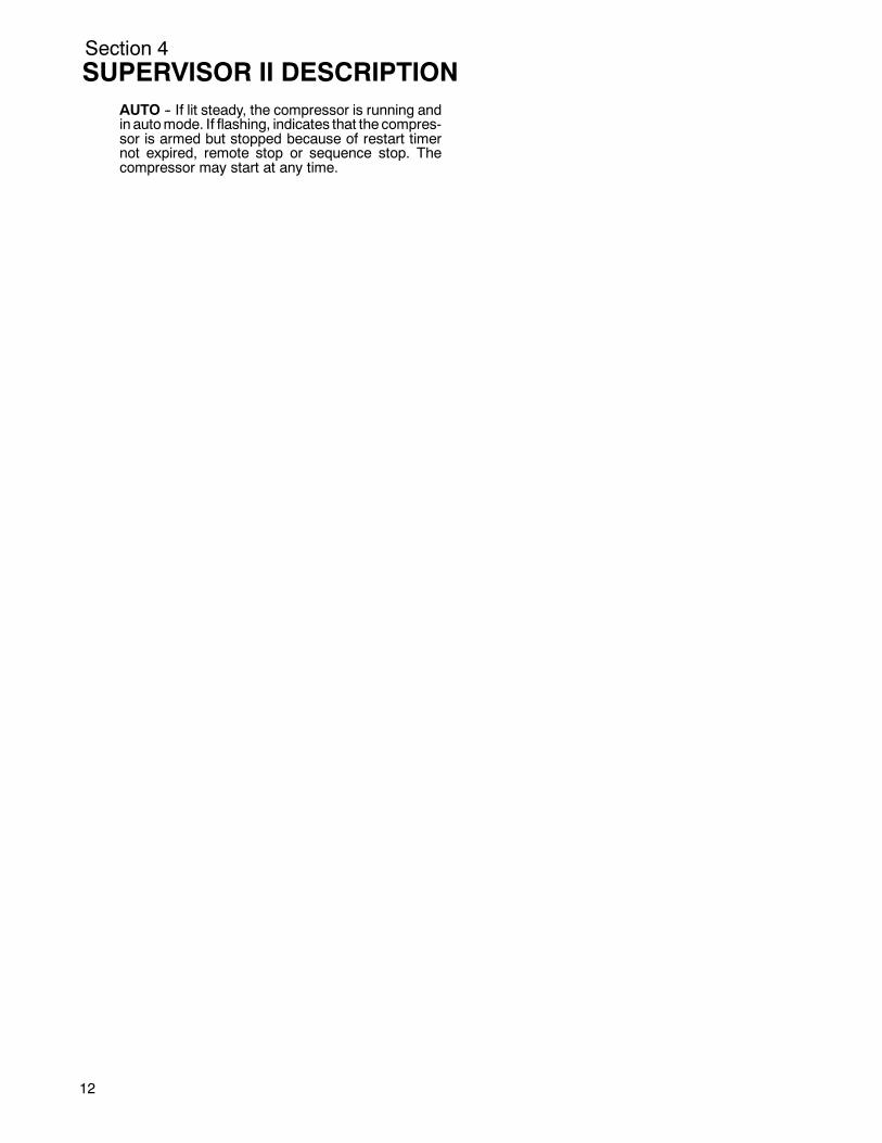
AUTO -- If lit steady, the compressor is running andin automode. If flashing, indicates that the compres-sor is armed but stopped because of restart timernot expired, remote stop or sequence stop. Thecompressor may start at any time.
Section 5COMPRESSOR SYSTEMS
5.1 INTRODUCTIONYour new Sullair lubricated rotary screw air com-pressor will provide you with a unique experience inimproved reliability and greatly reduced mainte-nance.
Compared to other types of compressors, the Sull-air rotary screw is unique in mechanical reliability,with “no wear” and “no inspection” required of theworking parts within the compressor unit.
Read Section 6 (Maintenance) to see how surpris-ingly easy it is to keep your air compressor in topop-erating condition. Should any questions arise whichcannot be answered in the following text, call yournearest Sullair representative or the Sullair Corpo-ration Service Department. (See back cover).
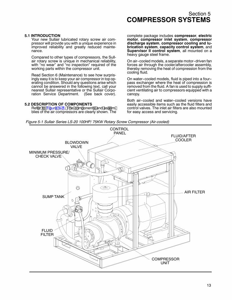
5.2 DESCRIPTION OF COMPONENTSRef er t o F igur e 5 -- 1. T he c om ponent s and as s em -blies of the air compressors are clearly shown. The
complete package includes compressor, electricmotor, compressor inlet system, compressordischarge system, compressor cooling and lu-brication system, capacity control system, andSupervisor II control system, all mounted on aheavy gauge steel frame.
On air--cooledmodels, a separate motor--driven fanforces air through the cooler/aftercooler assembly,thereby removing the heat of compression from thecooling fluid.
On water--cooled models, fluid is piped into a four--pass exchanger where the heat of compression isremoved from the fluid. A fan is used to supply suffi-cient ventilating air to compressors equipped with acanopy.
Both air--cooled and water--cooled versions haveeasily accessible items such as the fluid filters andcontrol valves. The inlet air filters are also mountedfor easy access and servicing.
CONTROLPANEL
FLUID/AFTERCOOLER
MINIMUM PRESSURE/CHECK VALVE
AIR FILTER
FLUIDFILTER
COMPRESSORUNIT
SUMP TANK
BLOWDOWNVALVE
Figure 5-1 Sullair Series LS-20 100HP/ 75KW Rotary Screw Compressor (Air-cooled)
13
Section 5COMPRESSOR SYSTEMS
14
5.3 SULLAIR COMPRESSOR UNIT, FUNCTIONALDESCRIPTIONSullair air compressors feature the Sullair compres-sor unit, a single--stage, positive displacement, lu-bricated--type compressor. This unit provides con-tinuous pulse--free air compression to meet yourneeds. With a Sullair compressor, there is no main-tenance or inspection of the internal parts of thecompressor unit permitted in accordance with theterms of the warranty.
Sullair 24KT compressors are filled with a fluidwhich rarely needs to be changed. In the event achangeormake--up fluid is required, use only Sullair24KT fluid.
WARNING!
Mixing of other lubricantswithin the compressorunit will void all warranties!
Sullair recommends that a 24KT sample be taken atthe first filter change and sent to the factory for anal-ysis. This is a free service. The sample kit with in-struction and self--addressed container is to be sup-plied by your Sullair representative at start--up. Theuser will receive an analysis report with recommen-dations.
Fluid is injected into the compressor unit in largequantities and mixes directly with the air as the ro-tors turn, compressing the air. The fluid flow hasthree primary functions:SControls the rise of air temperature normally asso-ciated with the heat of compression.
S Seals the leakage paths between the rotors andthe stator andalsobetween the rotors themselves.
S Acts as a lubricating film between the rotors allow-ing one rotor to directly drive the other, which is anidler.
After the air/fluid mixture is discharged from thecompressor unit, the fluid is separated from the air.At this time, the air flows to the service line and thefluid is cooled in preparation for re--injection.
The fluid also serves as lubricant for theanti--frictionbearings and the drive gear sets.
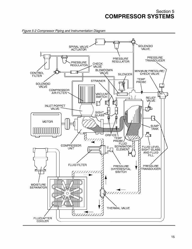
5.4 COMPRESSOR COOLING AND LUBRICATIONSYSTEM, FUNCTIONAL DESCRIPTIONRefer to Figures 5--2 and 5--3. The cooling and lu-brication system (air--cooled version) consists of afan, radiator--type cooler/aftercooler assembly,full--flowmain line filter, thermal valve and inter-connecting piping.
For the water--cooled models, a shell and tube fluidcooler, aftercooler and water--flow regulating valveare substituted for the radiator--type cooler on air--cooled compressors.
The pressure in the receiver/sump causes fluid flowby forcing the fluid from thehighpressure areaof thesump to an area of lower pressure in the compres-sor unit.
Fluid flows from the bottom of the receiver/sump tothe thermal valve. The thermal valve is fully open tothe compressor unit when the fluid temperature isbelow 170_F (77_C). The fluid passes through thethermal valve, themain filter and directly to the com-pressor unit where it lubricates, cools and seals therotors and the compression chamber.
As the discharge temperature rises above 170_F(77_C), due to the heat of compression, the thermalvalve begins to close and a portion of the fluid thenflows through the cooler. From the cooler, the fluidflows to themain filter andon to the compressorunit.
The filter has a replacement element and an integralpressure bypass valve. When the element pressuredrop exceeds 20 psid (1.4 bar), an internal switchcontact opens and the Supervisor II module dis-plays a maintenance requirement message.
Water--cooled versions of the compressor have awater--flow regulating valve. This valve automatical-ly shuts off thewater supply when the compressor isshut down. In addition, water--cooledmodels haveawater pressure switch to prevent operation with in-adequate water pressure.
5.5 COMPRESSOR DISCHARGE SYSTEM, FUNC-TIONAL DESCRIPTIONRefer to Figure 5--3. The compressor unit dis-charges the compressed air/fluid moisture into thecombination receiver/sump. The receiver has threefunctions:S It acts as a primary fluid separator.S Serves as the compressor fluid sump.S Houses the final fluid separator elements.The compressed air/fluid mixture enters the receiv-er and is directed against a curved shroud. Its direc-tion of movement is changed and its velocity signifi-cantly reduced, thus causing large droplets of fluidto form and fall to the bottom of the receiver/sump.The fractional percentage of fluid remaining in thecompressed air collects on the surface of the dualseparator elements as the compressed air flowsthrough them. Two return lines (or scavenge tubes)lead from the bottom of each separator element tothe inlet region of the compressor unit. Fluid collect-ing on the bottom of each separator is returned tothe compressor by a pressure difference betweenthe receiver and the compressor inlet. Sight glassesare located in the return lines to observe this fluidflow. There are also orifices in these return lines(protectedby strainers) to assure proper flow.Whenthe total pressure drop across the elements ex-ceeds 10 psid (0.7 bar), the Supervisor II moduledisplays a maintenance requirement message.
The receiver is an ASME pressure vessel. A com-bination minimum pressure/check valve, locateddownstream from the separator, assures a mini-mum receiver pressure of 50psig (3.5 bar) duringallconditions. This pressure is necessary for properair/fluid separation and proper fluid circulation whilesupplying air to the system. This valve also acts as a
Section 5COMPRESSOR SYSTEMS
Figure 5-2 Compressor Piping and Instrumentation Diagram
15

Section 5COMPRESSOR SYSTEMS
16
check valve preventing compressed air in the ser-vice line from bleeding back into the receiver onshutdown and during operation on the compressorin an unloaded condition.
A pressure relief valve (located on the wet side ofthe separator) is set to open if thesumppressureex-ceeds 200 psig (13.8 bar). For added safety the Su-pervisor II module is programmed to shutdown the
package when:
a) A pressure level, above unload setting but be-low relief valve setting, is reached.
b) A temperature level exceeding 240_F (116_C)is reached.
See Supervisor II module functional description forfurther details on shutdown pressure levels.
Figure 5-3 Compressor Cooling, Lubrication and Discharge Systems Diagram
Section 5COMPRESSOR SYSTEMS
All Sullair compressor models are equipped with ahigh pressure shutdown protection to shut down thecompressor at 190psig (13.1 bar). This prevents thepressure relief valve from opening under routineconditions, thereby preventing fluid loss through thepressure relief valve. A temperature switch will shutdown the compressor if the discharge temperaturereaches 240_F (115_C).
WARNING!
DO NOT remove caps, plugs, and/or other com-ponents when compressor is running or pressur-ized.
Stop compressor and relieve all internal pressurebefore doing so.
Fluid is added to the sump via a capped fluid filleropening, placed lowon the tank to prevent overfillingof the sump. A sight glass enables the operator tovisually monitor the sump fluid level.
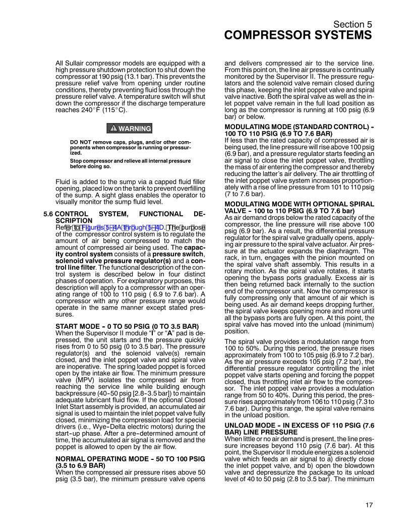
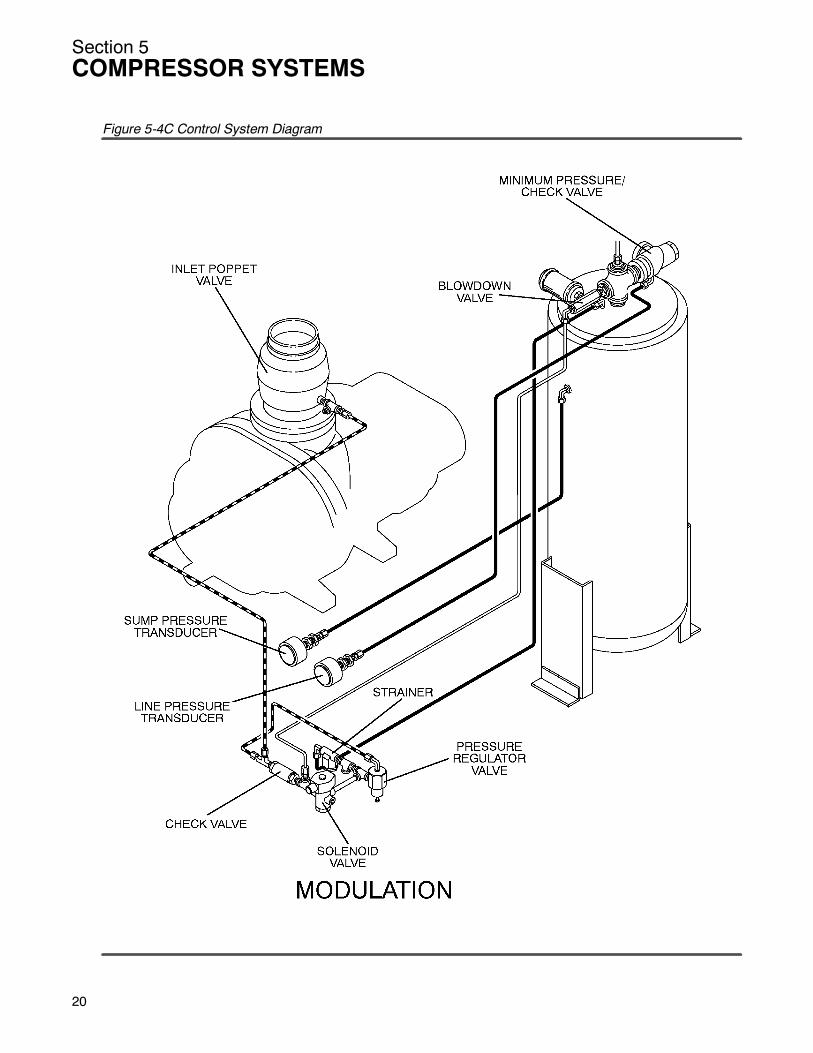
5.6 CONTROL SYSTEM, FUNCTIONAL DE-SCRIPTIONRef er t o F igur es 5 -- 4A t hr ough 5 -- 4D. T he pur pos eof the compressor control system is to regulate theamount of air being compressed to match theamount of compressed air being used. The capac-ity control system consists of a pressure switch,solenoid valve pressure regulator(s) and a con-trol line filter. The functional description of the con-trol system is described below in four distinctphases of operation. For explanatory purposes, thisdescription will apply to a compressor with an oper-ating range of 100 to 110 psig ( 6.9 to 7.6 bar). Acompressor with any other pressure range wouldoperate in the same manner except stated pres-sures.
START MODE -- 0 TO 50 PSIG (0 TO 3.5 BAR)When the Supervisor II module “I” or “A” pad is de-pressed, the unit starts and the pressure quicklyrises from 0 to 50 psig (0 to 3.5 bar). The pressureregulator(s) and the solenoid valve(s) remainclosed, and the inlet poppet valve and spiral valveare inoperative. The spring loaded poppet is forcedopen by the intake air flow. The minimum pressurevalve (MPV) isolates the compressed air fromreaching the service line while building enoughbackpressure (40--50 psig [2.8--3.5 bar]) tomaintainadequate lubricant fluid flow. If the optional ClosedInlet Start assembly is provided, an accumulated airsignal is used to maintain the inlet poppet valve fullyclosed, minimizing the compression load for specialdrivers (i.e., Wye--Delta electric motors) during thestart--up phase. After a pre--determined amount oftime, the accumulated air signal is removed and thepoppet is allowed to open by the air flow.
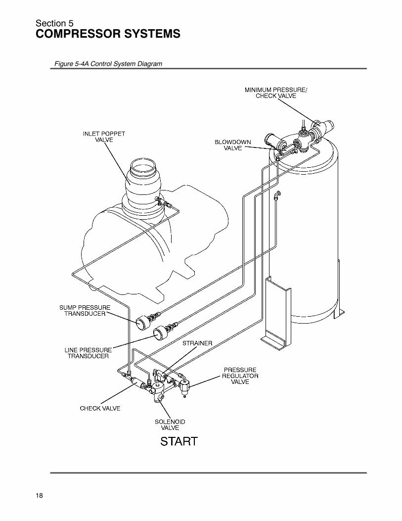
NORMAL OPERATING MODE -- 50 TO 100 PSIG(3.5 to 6.9 BAR)When the compressed air pressure rises above 50psig (3.5 bar), the minimum pressure valve opens
and delivers compressed air to the service line.From this point on, the line air pressure is continuallymonitored by the Supervisor II. The pressure regu-lators and the solenoid valve remain closed duringthis phase, keeping the inlet poppet valve and spiralvalve inactive. Both the spiral valve as well as the in-let poppet valve remain in the full load position aslong as the compressor is running at 100 psig (6.9bar) or below.
MODULATINGMODE (STANDARDCONTROL) --100 TO 110 PSIG (6.9 TO 7.6 BAR)If less than the rated capacity of compressed air isbeingused, the line pressurewill riseabove100psig(6.9 bar), and a pressure regulator starts feeding anair signal to close the inlet poppet valve, throttlingthemass of air entering the compressor and therebyreducing the latter’s air delivery. The air throttling ofthe inlet poppet valve system increases proportion-ately with a rise of line pressure from 101 to 110psig(7 to 7.6 bar).
MODULATING MODEWITH OPTIONAL SPIRALVALVE -- 100 to 110 PSIG (6.9 TO 7.6 bar)As air demand drops below the rated capacity of thecompressor, the line pressure will rise above 100psig (6.9 bar). As a result, the differential pressureregulator for the spiral valve gradually opens, apply-ing air pressure to the spiral valve actuator. Air pres-sure at the actuator expands the diaphragm. Therack, in turn, engages with the pinion mounted onthe spiral valve shaft assembly. This results in arotary motion. As the spiral valve rotates, it startsopening the bypass ports gradually. Excess air isthen being returned back internally to the suctionend of the compressor unit. Now the compressor isfully compressing only that amount of air which isbeing used. As air demand keeps dropping further,the spiral valve keeps opening more and more untilall the bypass ports are fully open. At this point, thespiral valve has moved into the unload (minimum)position.
The spiral valve provides a modulation range from100 to 50%. During this period, the pressure risesapproximately from 100 to 105 psig (6.9 to 7.2 bar).As the air pressure exceeds 105 psig (7.2 bar), thedifferential pressure regulator controlling the inletpoppet valve starts opening and forcing the poppetclosed, thus throttling inlet air flow to the compres-sor. The inlet poppet valve provides a modulationrange from 50 to 40%. During this period, the pres-sure rises approximately from106 to 110psig (7.3 to7.6 bar). During this range, the spiral valve remainsin the unload position.
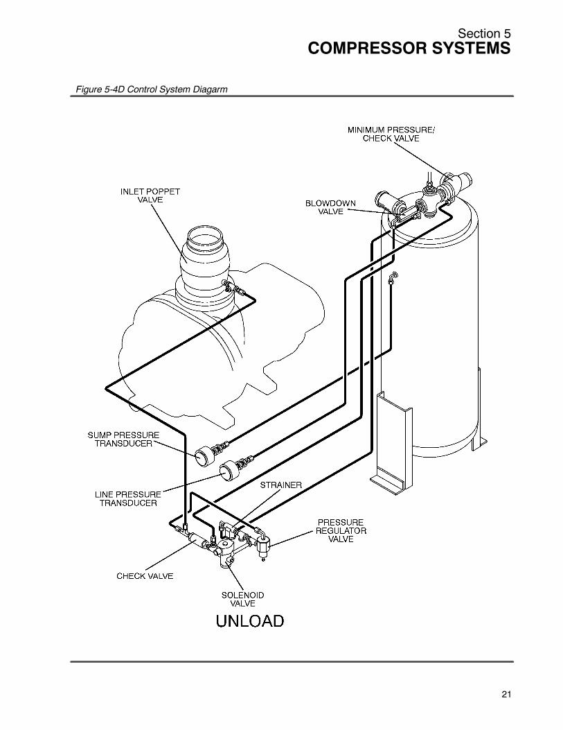
UNLOAD MODE -- IN EXCESS OF 110 PSIG (7.6BAR) LINE PRESSUREWhen little or noair demand is present, the line pres-sure increases beyond 110 psig (7.6 bar). At thispoint, the Supervisor II module energizes a solenoidvalve which feeds an air signal to a) directly closethe inlet poppet valve, and b) open the blowdownvalve and depressurize the package to its unloadlevel of 40 to 50 psig (2.8 to 3.5 bar). The minimum
17
Section 5COMPRESSOR SYSTEMS
18
Figure 5-4A Control System Diagram
Section 5COMPRESSOR SYSTEMS
Figure 5-4B Control System Diagram
19
Section 5COMPRESSOR SYSTEMS
20
Figure 5-4C Control System Diagram
Section 5COMPRESSOR SYSTEMS
Figure 5-4D Control System Diagarm
21
Section 5COMPRESSOR SYSTEMS
22
pressure valve now isolates the sump vessel fromthe service line.
If the Supervisor II module is operating on an “I”mode, the unit runs unloaded until the line pressurefalls below 100 psig (6.9 bar), at which point it pro-ceeds to theNormalModulatingMode. If on the oth-er hand, the Supervisor II module is operating in the“A” mode, the unit runs unloaded for a pre--setlength of time, and unless the line pressure falls be-low the 100 psig (6.9 bar) level, it stops at the end ofthis period. Once the line pressure falls below the100 psig (6.9 bar) level, the compressor automati-cally restarts, followed by package operation in theLoad mode.
When the line pressure drops back to 100 psig (6.9bar) due to an increase in the air demand, Supervi-sor II energizes the solenoid valve allowing the airpressure behind the inlet poppet valve to be ventedthrough the solenoid valve exhaust port. The blow-down valve closes, and the inlet poppet valveopens. Also the air pressure at the spiral valve ac-tuator diaphragm is reduced through a vent hole atthe spiral valve differential pressure regulator, and aspring in the actuator causes the spiral valve to re-turn to the full load (maximum) position.
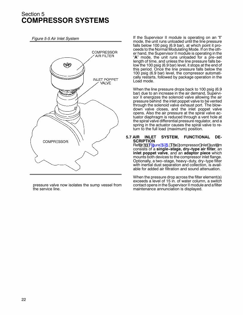
5.7 AIR INLET SYSTEM, FUNCTIONAL DE-SCRIPTIONRef er t o F igure 5 -- 5. T he compressor inlet syst emconsists of a single--stage, dry--type air filter, aninlet poppet valve, and an adaptor piece whichmounts both devices to the compressor inlet flange.Optionally, a two--stage, heavy--duty, dry--type filterwith inertial dust separation and collection, is avail-able for added air filtration and sound attenuation.
When the pressure drop across the filter element(s)exceeds a level of 15 in. of water column, a switchcontact opens in theSupervisor II module anda filtermaintenance annunciation is displayed.
Figure 5-5 Air Inlet System

Section 6COMPRESSOR OPERATION
6.1 INTRODUCTIONWhile Sullair has built into the 20 Series package acomprehensive array of controls and indicators toassure its proper operation, the user should recog-nize and interpret readings which call for service orindicate the onset of a malfunction. Before startingthe unit, the user should become familiar with thecontrols and indicators -- their purpose, location,
and use.
6.2 PURPOSE OF CONTROLSAll Supervisor II module (Supervisor) related func-t ions and indic at or s ar e pr es ent ed in S ec t ion 4. 2, s oplease refer to that section for your information.Additional indicators and functions included in thepackage are as follows:
CONTROL OR INDICATOR PURPOSE
EMERGENCY STOP SWITCH Pushing in this switch, found adjacent to the SupervisorII, cuts all AC outputs from the latter and de--energizesthe starter. A fault message (E STOP) is displayed bythe Supervisor II until the button is pulled out and the “O”pad is depressed.
THERMAL O/L RESET Momentarily pushing this button, foundon the starter’sthermal overload element housing, re--closes the lat-ter’s contacts after a current overload takes place.Please be aware that the elements must be allowed tocool sufficiently before resetting.
INLET POPPET VALVE Throttles the air flow to the compressor inlet in order tomatchair supply to thedemand. Also prevents air/fluidbackflow through compressor inlet during shutdown.
SPIRAL VALVE (OPTIONAL) Internally bypasses and controls the air flow capacityof the compressor, in order to match air supply to thedemand. This device is optional.
PRESSURE REGULATOR (INLET POPPETVALVE) Opens a pressure line between the sump and the inlet
poppet valve, allowing it to regulate air delivery accord--ing to the air demand.
PRESSURE REGULATOR (WITH OPTIONALSPIRAL VALVE) Opens a pressure line between the service line and
the spiral valve actuator allowing the spiral valve toregulate air delivery according to air demand.
SOLENOID VALVE Electrically actuated, 3--way valve which controls theflow of pneumatic logic signals. Used throughout pack-age to:SOpen the blowdown valve.SClose the inlet poppet valve during shutdown opera--tion.SClose the spiral valve during shutdown operation.
MINIMUM PRESSURE VALVE Maintains 50 psig (3.5 bar) pressure in sump vessel.When pressure falls below 40 psig (2.8 bar), it closesand isolates the sump vessel from the air service line,thus preventing compressed air backflow during un-loading or shutdown.
PRESSURE RELIEF VALVE Vents the sump vessel to atmosphere if the com-pressed air pressure exceeds 200 psig (13.8 bar). Itsoperation indicates fault with the Supervisor II opera-tion or its programming.
BLOWDOWN VALVE ASSEMBLY Vents the sump vessel to atmosphere during unload-ing and shutdown.
23
Section 6COMPRESSOR OPERATION
2
CONTROL OR INDICATOR PURPOSE
THERMAL MIXING VALVE Bypasses fluid flow around the cooler until the formerreaches a temperature of 170_F (77_C).Useful for fastwarm--up during start. Maintains a minimum tempera-ture of 180_F (82_C) during periods of low load or lowambient temperatures.
SUMP SIGHT GLASS Indicates level of lubricant in the sump. Located on thesump side, it should show half--full (compressorstopped) for proper fluid level.
SEPARATOR RETURN LINE SIGHT GLASSES Indicate fluid flow in the separator return lines. Largeflow should be visible during full load operation; little tono flow during unloaded operation. Sluggish flow dur-ing full load operation indicates the need to clean thestrainers fitted to the return lines.
WATER PRESSURE SWITCH De--energizes the starter, via the Supervisor II, if thewater pressure falls below 10 psig (0.7 bar). Thisswitch is not adjustable. Used on water--cooled pack-ages only.
WATER REGULATOR VALVE Regulates the amount of water used, as well as shutsthe water flow off when the package is not running.Used on water--cooled packages only.
DRAIN GLOBE VALVES Furnished as manual backup and bypass for the auto-matic (float--type) drain valve used in the condensateseparator vessel. Also used as lubricant sump drainvalve.
4
6.3 SUPERVISOR II OPERATING PARAMETERS--SET UPPressing the program key enters parameter displayand edit mode. Tomove to thenext parameter pressthe program key. To increment a parameter pressthe up arrow key or logo key. The logo key will incre-ment by 10. To decrement the value press the downarrow key.
Theparameters are displayed in the followingorder:
SSSS Unload pressure -- The pressure wherethe machine is unloaded. For example ifthis parameter is set to 110 psi (7.6 bar) themachine will unload when the line pressureis above 110 psi (7.6 bar).
UNLOAD100 PSI
SSSSLoad differential -- The pressure differen-tial below the unload pressure where themachine is loaded. For example if the un-load pressure is set to 110 psi (7.6 bar) andthe load differential is set to 10 psid (0.7bar), the machine will load when the line
pressure goes below 100 psi (6.9 bar).
LOAD10 PSI
SSSS P1 Max -- Maximum sump pressure. Analarm and shut down will occur when thesump pressure rises above this pressure.
P1 MAX135 PSI
SSSS Wye to delta transition timer -- For fullvoltage starters this parameter is set tozero.
WYE DELT10 SEC
SSSS Restart time -- Time to wait after powerupbefore starting machine. This parameter isused to keep several machines from start-ing at the same time after power up, or todelay start until other equipment is started.If disabled themachinewill not automatical-
Section 6COMPRESSOR OPERATION
ly start after power up.
RST TIME10 SEC
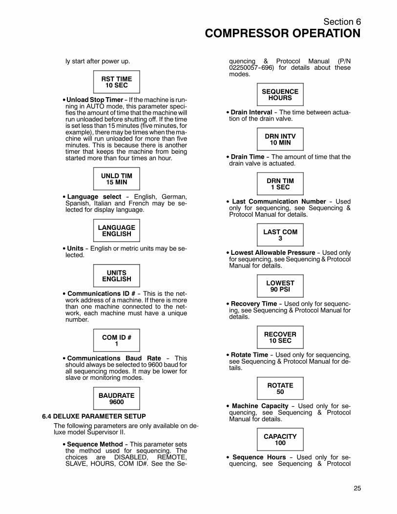
SSSSUnloadStopTimer -- If themachine is run-ning in AUTO mode, this parameter speci-fies the amount of time that themachinewillrun unloaded before shutting off. If the timeis set less than15minutes (fiveminutes, forexample), theremay be timeswhen thema-chine will run unloaded for more than fiveminutes. This is because there is anothertimer that keeps the machine from beingstarted more than four times an hour.
UNLD TIM15 MIN
SSSS Language select -- English, German,Spanish, Italian and French may be se-lected for display language.
LANGUAGEENGLISH
SSSS Units -- English or metric units may be se-lected.
UNITSENGLISH
SSSS Communications ID # -- This is the net-work address of a machine. If there is morethan one machine connected to the net-work, each machine must have a uniquenumber.
COM ID #1
SSSS Communications Baud Rate -- Thisshould always be selected to 9600 baud forall sequencing modes. It may be lower forslave or monitoring modes.
BAUDRATE9600
6.4 DELUXE PARAMETER SETUPThe following parameters are only available on de-luxe model Supervisor II.
SSSS Sequence Method -- This parameter setsthe method used for sequencing. Thechoices are DISABLED, REMOTE,SLAVE, HOURS, COM ID#. See the Se-
quencing & Protocol Manual (P/N02250057--696) for details about thesemodes.
SEQUENCEHOURS
SSSS Drain Interval -- The time between actua-tion of the drain valve.
DRN INTV10 MIN
SSSS Drain Time -- The amount of time that thedrain valve is actuated.
DRN TIM1 SEC
SSSS Last Communication Number -- Usedonly for sequencing, see Sequencing &Protocol Manual for details.
LAST COM3
SSSS Lowest Allowable Pressure -- Used onlyfor sequencing, see Sequencing & ProtocolManual for details.
LOWEST90 PSI
SSSS Recovery Time -- Used only for sequenc-ing, see Sequencing & Protocol Manual fordetails.
RECOVER10 SEC
SSSS Rotate Time -- Used only for sequencing,see Sequencing & Protocol Manual for de-tails.
ROTATE50
SSSS Machine Capacity -- Used only for se-quencing, see Sequencing & ProtocolManual for details.
CAPACITY100
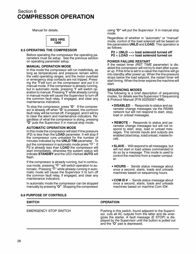
SSSS Sequence Hours -- Used only for se-quencing, see Sequencing & Protocol
25
Section 6COMPRESSOR OPERATION
26
Manual for details.
SEQ HRS1000
6.5 OPERATING THE COMPRESSORBefore operating the compressor the operating pa-rameters must be setup. See the previous sectionon operating parameter setup.
MANUAL OPERATION MODEIn this mode the compressor will run indefinitely, aslong as temperatures and pressure remain withinthe valid operating ranges, and the motor overloador emergency stop contacts are not tripped. Press-ing the “I”will turn on the compressor and put it inmanual mode. If the compressor is already running,but in automatic mode, pressing “I” will switch op-eration tomanual. Pressing “I” while already runningin manual mode will cause the Supervisor to turn offthe common fault relay, if engaged, and clear anymaintenance indicators.To stop the compressor, press “O”. If the compres-sor is already off when “O” is pressed, the commonfault relay will be turned off, if engaged, and it will tryto clear the alarm and maintenance indicators. Re-gardless of what the compressor is doing, pressing“O” puts the Supervisor II in manual stop mode.
AUTOMATIC OPERATION MODEIn thismode the compressorwill start if line pressure(P2) is less than the LOAD parameter. It will stop ifthe compressor runs unloaded for the number ofminutes indicated by the UNLD TIM parameter . Toput the compressor in automatic mode press “ ”. IfP2 is already less than LOAD the compressor willstart immediately, otherwise the system status willindicate STANDBY and the LEDmarked AUTO willflash.If the compressor is already running, but in continu-ous mode, pressing “ ” will switch operation to au-tomatic. Pressing “ ” while already running in auto-matic mode will cause the Supervisor II to turn offthe common fault relay, if engaged, and clear anymaintenance indicators.In automatic mode the compressor can be stoppedmanually by pressing “O”. Stopping the compressor
using “O” will put the Supervisor II in manual stopmode.Regardless of whether in “automatic” or “manual”mode, control of the load solenoid will be based onthe parametersUNLD and LOAD. This operation isas follows:P2 > UNLD ----> load solenoid turned offP2 < LOAD ----> load solenoid turned on
POWER FAILURE RESTARTIf the restart timer (RST TIME parameter) is dis-abled the compressor will not try to start after a pow-er up. If this time is set to a value themachine will gointo standby after power up. When the line pressuredrops below the load setpoint, the restart timer willstart timing.When the timer expires themachinewillstart.
SEQUENCING MODESThe following is a brief description of sequencingmodes, for details see the Supervisor II Sequencing& Protocol Manual (P/N 02250057--696).
SSSSDISABLED -- Responds to status and pa-rameter change messages via the RS485network but will not respond to start, stop,load or unload messages.
SSSS REMOTE -- Responds to status and pa-rameter change messages but will not re-spond to start, stop, load or unload mes-sages. The remote inputs and outputs areenabled (start/stop, load/unload,master/lo-cal).
SSSSSLAVE -- Will respond to all messages, butwill not start or load unless commanded todo so by a message. This mode is used tocontrol the machine from amaster comput-er.
SSSS HOURS -- Sends status message aboutonce a second, starts, loads and unloadsmachines based on sequencing hours.
SSSSCOM ID # -- Sends status message aboutonce a second, starts, loads and unloadsmachines based on machine Com ID#.
6.6 PURPOSE OF CONTROLS
SWITCH OPERATION
EMERGENCY STOP SWITCH Pushing in this switch, found adjacent to the Supervi-sor, cuts all AC outputs from the latter and de--ener-gizes the starter. A fault message (E STOP) is dis-played by the Supervisor until the button is pulled outand the “O” pad is depressed.

Section 6COMPRESSOR OPERATION
6.7 SUPERVISOR II OUTPUT RELAYS
RELAY OPERATION
RUN RELAY (K1) Contact closure energizes the compressor starter.*--DELTA (K2) A timed contact used to provide Wye--delta transition
time.UNLOAD/LOAD (K3) Controls ON LOAD/OFF LOAD operation of the load
control solenoid valve.COMMON FAULT (K4) May be used to provide remote indication of any pre--
alarm, maintenance or fault shutdown condition.DRAIN VALVE (K5) Deluxeonly -- controls a solenoid valve to provideauto-
matic condensate removal.FULL LOAD/MODULATE (K6) Deluxe only -- used with sequencing feature.
NOTE: All output relays will handle 8 amperes at 120/240 VAC.
6.8 MOTOR ROTATION CHECKAfter the electrical installation has been done, it isnecessary to check the direction of motor rotation.Pull out the EMERGENCY STOP button and pressonce, quickly and in succession, the (START) “I”and (STOP) “O” pads. This actionwill bump start themotor for a very short time.When looking at themo-tor rear end, the driveline should be rotating in thedirection indicated by the “Direction of Rotation” de-cal located on the top of the compressor/motoradapter piece. If the reversed rotation is noted, dis-connect the power to the starter and exchange anytwo of the three power input leads, then re--checkrotation. A “Direction of Rotation” decal is locatedonthe top of the compressor/motor adaptor piece.
6.9 INITIAL START--UP PROCEDUREThe followingprocedure should beused tomake theinitial start--up of the compressor.1. Read the preceding pages of this manual thor-
oughly.2. Jog motor to check for correct rotation of fan.3. Be sure that all preparations and checks de-
scribed in the Installation Section have beenmade.
4. Open the shut--off valve to the service line.5. Check for possible leaks in piping.6. Slowly close the shut--off valve to assure proper
nameplate pressure unload setting is correct.The compressor will unload at nameplate pres-sure. If adjustments are necessary, see ControlSystem Adjustments.
7. Observe theoperating temperature. If the operat-ing temperature exceeds 200_F (93_C), thecooling system and installation environmentshould be checked.
8. Open shut--off valve to the service line.9. Reinspect the compressor for temperature and
leaks the following day.
6.10 SUBSEQUENT START--UP PROCEDUREOnsubsequent start--ups, check that the proper lev-el is visible in the fluid level sight glass and simplypress “I” for manual or “ ” for automatic operation.When the compressor is running, observe the vari-ous parameter displays.
6.11 SHUTDOWN PROCEDURETo shut the compressor down, push “O” pad.
27

28
NOTES
Section 7MAINTENANCE
7.1 GENERALAs you proceed in reading this section, it will be easyto see that the maintenance program for the air com-pressor is quite minimal. The Supervisor II monitorsthe status of theair filter, fluid filter, and separatorele-ments. When maintenance to these devices is re-quired, the Supervisor II will display the appropriatemaintenancemessage and flash the location LEDonthe graphics map as a visual reminder.
WARNING!
DO NOT remove caps, plugs, and/or other compo-nentswhencompressor is running orpressurized.
Stop compressor and relieve all internal pressurebefore doing so.
7.2 DAILY OPERATIONFollowing a routine start, observe the various Super-visor II displays to check that normal readings are be-ingmade -- previous records are very helpful in deter-mining the normalcy of the measurements. Theseobservations should be made during all expectedmodes of operation (i.e. full load, no--load, differentline pressures, cooling water temperatures, etc.).
During the initial start--upor servicing of thepackage,fluid may have to be added to the sump vessel to re-store to anadequate level. Frequent fluid additions tomaintain said level would be indicative of excessivefluid consumption, and should be investigated -- seet he Tr oubles hoot ing S ec t ion 8 of t his m anual f orprobable cause and remedy.
7.3 MAINTENANCE AFTER INITIAL 50 HOURS OFOPERATIONAfter the initial 50 hours of operation, a few mainte-nance requirements are needed to rid the system ofany foreign materials. Perform the following mainte-nance operations to prevent unnecessary problems.
1. Clean the return line strainers.2. Clean the return line orifices.3. Change the fluid filter element.
7.4 MAINTENANCEEVERY1000HOURSOFOPERA-TION1. Clean the return line strainers.2. Change the fluid filter element.
7.5 PARTS REPLACEMENT AND ADJUSTMENTPROCEDURESPlease familiarize yourself with the safety guidelinesoffered in Section 1 of this manual before attemptingany maintenance on the package.
* Element Kit P/N 040899
*
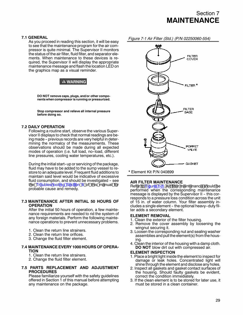
Figure 7-1 Air Filter (Std.) (P/N 02250060-554)
AIR FILTER MAINTENANCERef er t o F igur e 7 -- 1. A ir f ilt er m aint enanc e s hould beperformed when the corresponding maintenancemessage is displayed by the Supervisor II -- this cor-responds to a pressure loss condition across the unitof 15 in. of water column. Your filter assembly in-cludes a single element -- the optional heavy--duty fil-ter adds a secondary element.ELEMENT REMOVAL1. Clean the exterior of the filter housing.2. Remove the cover assembly by loosening the
wingnut securing it.3. Loosen the corresponding nut and sealingwasher
assemblies andpull the element(s) from thehous-ing.
4. Clean the interior of the housingwith a dampcloth.DO NOT blow dirt out with compressed air.
ELEMENT INSPECTION1. Placeabright light inside the element to inspect for
damage or leak holes. Concentrated light willshine through theelement anddiscloseanyholes.
2. Inspect all gaskets and gasket contact surfaces ofthe housing. Should faulty gaskets be evident,correct the condition immediately.
3. If the clean element is to be stored for later use, itmust be stored in a clean container.
29
Section 7MAINTENANCE
30
* Repair Kit P/N 250025-526
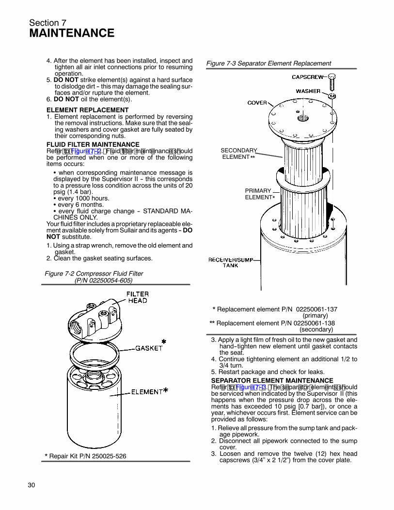
(P/N 02250054-605)Figure 7-2 Compressor Fluid Filter
* Replacement element P/N 02250061-137
** Replacement element P/N 02250061-138(secondary)
(primary)
SECONDARYELEMENT**
*PRIMARYELEMENT
Figure 7-3 Separator Element Replacement
4. After the element has been installed, inspect andtighten all air inlet connections prior to resumingoperation.5. DO NOT strike element(s) against a hard surfaceto dislodgedirt -- thismay damage the sealing sur-faces and/or rupture the element.
6. DO NOT oil the element(s).
ELEMENT REPLACEMENT1. Element replacement is performed by reversing
the removal instructions. Make sure that the seal-ing washers and cover gasket are fully seated bytheir corresponding nuts.
FLUID FILTER MAINTENANCERef er t o F igur e 7 -- 2. F luid f ilt er m aint enanc e s houldbe performed when one or more of the followingitems occurs:S when corresponding maintenance message isdisplayed by the Supervisor II -- this correspondsto a pressure loss condition across the units of 20psig (1.4 bar).S every 1000 hours.S every 6 months.S every fluid charge change -- STANDARD MA-CHINES ONLY.
Your fluid filter includes aproprietary replaceable ele-ment available solely fromSullair and its agents --DONOT substitute.1. Using a strapwrench, remove the old element and
gasket.2. Clean the gasket seating surfaces.
3. Apply a light film of fresh oil to the new gasket andhand--tighten new element until gasket contactsthe seat.
4. Continue tightening element an additional 1/2 to3/4 turn.
5. Restart package and check for leaks.
SEPARATOR ELEMENT MAINTENANCERef er t o F igur e 7 -- 3. T he s epar at or elem ent s s houldbe servicedwhen indicated by the Supervisor II (thishappens when the pressure drop across the ele-ments has exceeded 10 psig [0.7 bar]), or once ayear, whichever occurs first. Element service can beprovided as follows:1. Relieve all pressure from the sump tank and pack-age pipework.2. Disconnect all pipework connected to the sump
cover.3. Loosen and remove the twelve (12) hex head
capscrews (3/4” x 2 1/2”) from the cover plate.
Section 7MAINTENANCE
4. Lift the cover plate from the sump.5. Remove the two (2) nested separator elements.6. Scrape the old gasket material from the cover and
sump flange -- avoid dropping any scraps into thesump.
7. Inspect the sump vessel for rust, dirt, etc.8.
WARNING!
DO NOT remove grounding staples from the gas-kets. DONOT use any typeof gasket eliminator. Do-ing so will interfere with grounding circuit and maycause severe shock.
Reinsert the separator element, with gasket at-tached, into the sump, taking care not to dent theformer against the tank opening.
9. Replace the cover plate and re--fasten washer/capscrew assemblies to 155 ft.--lbs. (211Nm).
10. Re--connect all pipework, making sure the returnlines extend within 1/4” (6.4mm) from the bottomof each element. This will insure proper fluid re-turn during operation.
11. Clean the return line strainers.
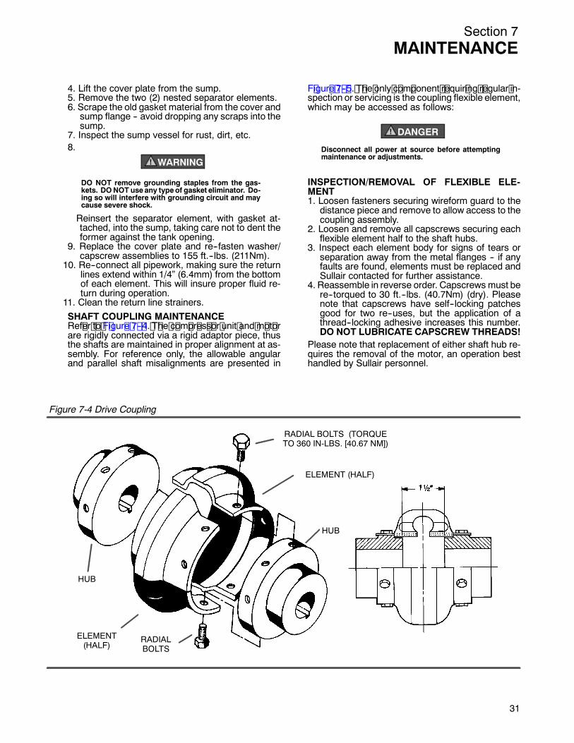
SHAFT COUPLING MAINTENANCERef er t o F igur e 7 -- 4. T he c om pr es s or unit and m ot orare rigidly connected via a rigid adaptor piece, thusthe shafts are maintained in proper alignment at as-sembly. For reference only, the allowable angularand parallel shaft misalignments are presented inF igur e 7 -- 5. T he only c om ponent r equir ing r egular in-spection or servicing is the coupling flexible element,which may be accessed as follows:
DANGER!
Disconnect all power at source before attemptingmaintenance or adjustments.
INSPECTION/REMOVAL OF FLEXIBLE ELE-MENT1. Loosen fasteners securing wireform guard to the
distance piece and remove to allow access to thecoupling assembly.
2. Loosen and remove all capscrews securing eachflexible element half to the shaft hubs.
3. Inspect each element body for signs of tears orseparation away from the metal flanges -- if anyfaults are found, elements must be replaced andSullair contacted for further assistance.
4. Reassemble in reverse order. Capscrews must bere--torqued to 30 ft.--lbs. (40.7Nm) (dry). Pleasenote that capscrews have self--locking patchesgood for two re--uses, but the application of athread--locking adhesive increases this number.DO NOT LUBRICATE CAPSCREW THREADS!
Please note that replacement of either shaft hub re-quires the removal of the motor, an operation besthandled by Sullair personnel.
RADIAL BOLTS (TORQUETO 360 IN-LBS. [40.67 NM])
ELEMENT (HALF)
HUB
HUB
RADIALBOLTS
ELEMENT(HALF)
Figure 7-4 Drive Coupling
31

Section 7MAINTENANCE
3
Figure 7--5 Drive Coupling Alignment
Max Operating MisalignmentCoupling Capscrew
Angular
Degrees
.5 .005
TighteningTorquelb.--in.
Gap .030Inches
ParallelOffsetInches
T.I.R..0051.50360
Inches
Angular misalignment in inches equals maximum Aminus minimum B. DO NOT exceed values in tableabove.
(I)
(I)
Table 1 - Installation Data
2
Section 8TROUBLESHOOTING
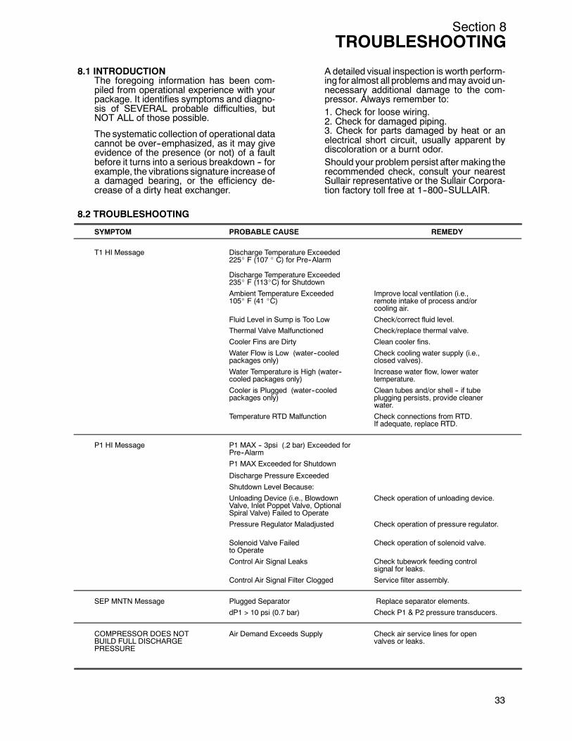
8.1 INTRODUCTIONThe foregoing information has been com-piled from operational experience with yourpackage. It identifies symptoms and diagno-sis of SEVERAL probable difficulties, butNOT ALL of those possible.
The systematic collection of operational datacannot be over--emphasized, as it may giveevidence of the presence (or not) of a faultbefore it turns into a serious breakdown -- forexample, the vibrations signature increaseofa damaged bearing, or the efficiency de-crease of a dirty heat exchanger.
A detailed visual inspection is worth perform-ing for almost all problems andmay avoid un-necessary additional damage to the com-pressor. Always remember to:1. Check for loose wiring.2. Check for damaged piping.3. Check for parts damaged by heat or anelectrical short circuit, usually apparent bydiscoloration or a burnt odor.Should your problem persist after making therecommended check, consult your nearestSullair representative or the Sullair Corpora-tion factory toll free at 1--800--SULLAIR.
8.2 TROUBLESHOOTING
SYMPTOM PROBABLE CAUSE REMEDY
T1 HI Message Discharge Temperature Exceeded225_ F (107 _ C) for Pre--Alarm
Discharge Temperature Exceeded235_ F (113_C) for Shutdown
Ambient Temperature Exceeded Improve local ventilation (i.e.,105_ F (41 _C) remote intake of process and/or
cooling air.
Fluid Level in Sump is Too Low Check/correct fluid level.Thermal Valve Malfunctioned Check/replace thermal valve.
Cooler Fins are Dirty Clean cooler fins.
Water Flow is Low (water--cooled Check cooling water supply (i.e.,packages only) closed valves).
Water Temperature is High (water-- Increase water flow, lower watercooled packages only) temperature.
Cooler is Plugged (water--cooled Clean tubes and/or shell -- if tubepackages only) plugging persists, provide cleaner
water.
Temperature RTD Malfunction Check connections from RTD.If adequate, replace RTD.
P1 HI Message P1 MAX -- 3psi (.2 bar) Exceeded forPre--Alarm
P1 MAX Exceeded for Shutdown
Discharge Pressure Exceeded
Shutdown Level Because:
Unloading Device (i.e., Blowdown Check operation of unloading device.Valve, Inlet Poppet Valve, OptionalSpiral Valve) Failed to Operate
Pressure Regulator Maladjusted Check operation of pressure regulator.
Solenoid Valve Failed Check operation of solenoid valve.to Operate
Control Air Signal Leaks Check tubework feeding controlsignal for leaks.
Control Air Signal Filter Clogged Service filter assembly.
SEP MNTN Message Plugged Separator Replace separator elements.
dP1 > 10 psi (0.7 bar) Check P1 & P2 pressure transducers.
COMPRESSOR DOES NOT Air Demand Exceeds Supply Check air service lines for openBUILD FULL DISCHARGE valves or leaks.PRESSURE
33
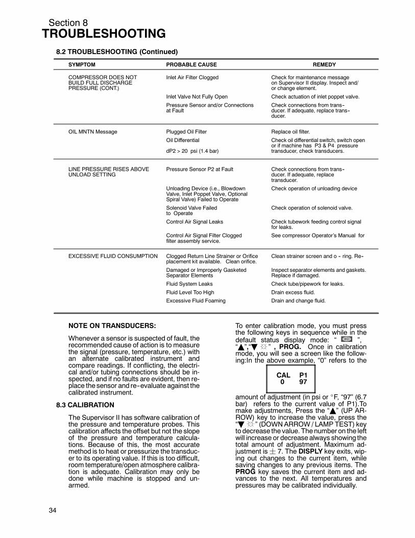
Section 8TROUBLESHOOTING
3
8.2 TROUBLESHOOTING (Continued)
SYMPTOM PROBABLE CAUSE REMEDY
COMPRESSOR DOES NOT Inlet Air Filter Clogged Check for maintenance messageBUILD FULL DISCHARGE on Supervisor II display. Inspect and/PRESSURE (CONT.) or change element.
Inlet Valve Not Fully Open Check actuation of inlet poppet valve.
Pressure Sensor and/or Connections Check connections from trans--at Fault ducer. If adequate, replace trans--
ducer.
OIL MNTN Message Plugged Oil Filter Replace oil filter.
Oil Differential Check oil differential switch, switch openor if machine has P3 & P4 pressure
dP2 > 20 psi (1.4 bar) transducer, check transducers.
LINE PRESSURE RISES ABOVE Pressure Sensor P2 at Fault Check connections from trans--UNLOAD SETTING ducer. If adequate, replace
transducer.
Unloading Device (i.e., Blowdown Check operation of unloading deviceValve, Inlet Poppet Valve, OptionalSpiral Valve) Failed to Operate
Solenoid Valve Failed Check operation of solenoid valve.to Operate
Control Air Signal Leaks Check tubework feeding control signalfor leaks.
Control Air Signal Filter Clogged See compressor Operator’s Manual forfilter assembly service.
EXCESSIVE FLUID CONSUMPTION Clogged Return Line Strainer or Orifice Clean strainer screen and o -- ring. Re--placement kit available. Clean orifice.
Damaged or Improperly Gasketed Inspect separator elements and gaskets.Separator Elements Replace if damaged.
Fluid System Leaks Check tube/pipework for leaks.
Fluid Level Too High Drain excess fluid.
Excessive Fluid Foaming Drain and change fluid.
4
NOTE ON TRANSDUCERS:
Whenever a sensor is suspected of fault, therecommended cause of action is to measurethe signal (pressure, temperature, etc.) withan alternate calibrated instrument andcompare readings. If conflicting, the electri-cal and/or tubing connections should be in-spected, and if no faults are evident, then re-place the sensor and re--evaluate against thecalibrated instrument.
8.3 CALIBRATION
The Supervisor II has software calibration ofthe pressure and temperature probes. Thiscalibration affects the offset but not the slopeof the pressure and temperature calcula-tions. Because of this, the most accuratemethod is to heat or pressurize the transduc-er to its operating value. If this is too difficult,room temperature/open atmosphere calibra-tion is adequate. Calibration may only bedone while machine is stopped and un-armed.
To enter calibration mode, you must pressthe following keys in sequence while in thedefault status display mode: “ ”,“Y”,“B ” , PROG. Once in calibrationmode, you will see a screen like the follow-ing:In the above example, “0” refers to the
CAL P1970
amount of adjustment (in psi or _F, “97” (6.7bar) refers to the current value of P1).Tomake adjustments, Press the “Y” (UP AR-ROW) key to increase the value, press the“B ” (DOWNARROW / LAMP TEST) keyto decrease the value. Thenumber on the leftwill increase or decreasealways showing thetotal amount of adjustment. Maximum ad-justment is¦ 7. The DISPLY key exits, wip-ing out changes to the current item, whilesaving changes to any previous items. ThePROG key saves the current item and ad-vances to the next. All temperatures andpressures may be calibrated individually.

Section 9ILLUSTRATIONS AND PARTS LIST
9.1 PROCEDURE FOR ORDERING PARTSParts should be ordered from the nearest Sullair Representative or the Representative from whom the com-pressorwas purchased. If for any reason parts cannot beobtained in this manner, contact the factory directly atthe address, fax or phone numbers below.
Whenorderingparts always indicate theSerial Numberof the compressor. This canbeobtained from theBill ofLading for the compressor or from the Serial Number Plate located on the compressor.
The genuine Sullair service parts listed meet or exceed the demands of this compressor. Use of replacementparts other than those approved by Sullair Corporation may lead to hazardous conditions over which SullairCorporation has no control. Such conditions include, but are not limited to, bodily injury and compressor failure.
SULLAIR ASIA, LTD.Sullair Road, No. 1Chiwan, Shekou
Shenzhen, Guangdong PRV.PRC POST CODE 518068Telephone: 755-6851686
Fax: 755-6853473SULLAIR CORPORATION3700 East Michigan Boulevard
Michigan City, Indiana 46360 U.S.A.Phone: 1-800-SULLAIR (U.S.A. Only) or
1-219-879-5451Fax: (219) 874-1273
Fax: (219) 874-1835 (Parts)Fax: (219) 874-1205 (Service)
SULLAIR EUROPE, S.A.Zone Des Granges BP 82
42602 Montbrison Cedex, FranceTelephone: 33-477968470
Fax: 33-477968499
9.2 RECOMMENDED SPARE PARTS LIST
DESCRIPTION KIT NUMBER QUANTITY
element for air filter 02250060--554 040899 1repair kit for blowdown valve 250030--276 02250045--132 1repair kit for thermal valve 001168 1repair kit for solenoid valve 250035--291 250038--848 1replacement coil for solenoid valve 250035--291 250035--292 1repair kit for solenoid valve 250038--674 250038--673 1replacement coil for solenoid valve 250038--674 250031--738 1repair kit for solenoid valve 250031--695 250031--737 1replacement coil for solenoid valve 250031--695 250031--738 1repair kit for solenoid valve 250038--675 250038--672 1replacement coil for solenoid valve 250038--675 250038--730 1repair kit for solenoid valve 250038--755 250038--676 1replacement coil for solenoid valve 250038--755 250038--730 1replacement solenoid for solenoid valve 250038--163 250031--322 1replacement valve for solenoid valve 250038--163 250031--278 1replacement timer for solenoid valve 250038--163 250038--164 1repair kit for separator/trap 410143 250033--038 1repair kit for fluid filter 02250054--605 250025--526 1repair kit for air inlet valve 02250060--988 02250053--273 1repair kit for pressure regulator 250017--280 250019--453 1repair kit for return line strainer 241771 241772 1repair kit primary separator element w/gaskets 02250061--137 1repair kit secondary separator element w/gaskets 02250061--138 1
(Continued on page 36)
PLEASE NOTE: WHEN ORDERING PARTS, INDICATE SERIAL NUMBER OF COMPRESSOR.
35
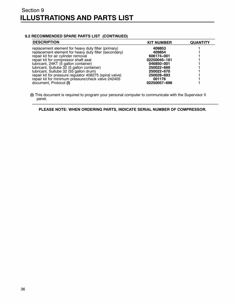
Section 9
ILLUSTRATIONS AND PARTS LIST
3
9.2 RECOMMENDED SPARE PARTS LIST (CONTINUED)
DESCRIPTION KIT NUMBER QUANTITYreplacement element for heavy duty filter (primary) 409853 1replacement element for heavy duty filter (secondary) 409854 1repair kit for air cylinder removal 606174--001 1repair kit for compressor shaft seal 02250045--161 1lubricant, 24KT (5 gallon container) 046850--001 1lubricant, Sullube 32 (5 gallon container) 250022--669 1lubricant, Sullube 32 (55 gallon drum) 250022--670 1repair kit for pressure regulator 408275 (spiral valve) 250028--693 1repair kit for minimum pressure/check valve 242405 001176 1document, Protocol (I) 02250057--696 1
(I) This document is required to program your personal computer to communicate with the Supervisor IIpanel.
PLEASE NOTE: WHEN ORDERING PARTS, INDICATE SERIAL NUMBER OF COMPRESSOR.
6

Section 9ILLUSTRATIONS AND PARTS LIST
37
NOTES

Section 9
ILLUSTRATIONS AND PARTS LIST
9.3 FRAME, MOTOR, COMPRESSOR AND PARTS
38
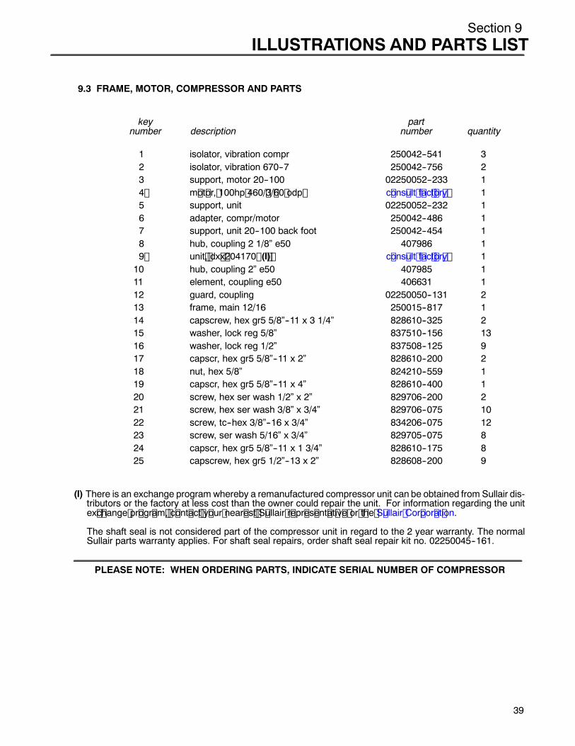
Section 9ILLUSTRATIONS AND PARTS LIST
9.3 FRAME, MOTOR, COMPRESSOR AND PARTS
key partnumber description number quantity
1 isolator, vibration compr 250042--541 32 isolator, vibration 670--7 250042--756 23 support, motor 20--100 02250052--233 14 m ot or, 100hp 460/ 3/ 60 odp c ons ult f ac t or y 15 support, unit 02250052--232 16 adapter, compr/motor 250042--486 17 support, unit 20--100 back foot 250042--454 18 hub, coupling 2 1/8” e50 407986 19 unit , dx x 204170 (I ) c ons ult f ac t or y 110 hub, coupling 2” e50 407985 111 element, coupling e50 406631 112 guard, coupling 02250050--131 213 frame, main 12/16 250015--817 114 capscrew, hex gr5 5/8”--11 x 3 1/4” 828610--325 215 washer, lock reg 5/8” 837510--156 1316 washer, lock reg 1/2” 837508--125 917 capscr, hex gr5 5/8”--11 x 2” 828610--200 218 nut, hex 5/8” 824210--559 119 capscr, hex gr5 5/8”--11 x 4” 828610--400 120 screw, hex ser wash 1/2” x 2” 829706--200 221 screw, hex ser wash 3/8” x 3/4” 829706--075 1022 screw, tc--hex 3/8”--16 x 3/4” 834206--075 1223 screw, ser wash 5/16” x 3/4” 829705--075 824 capscr, hex gr5 5/8”--11 x 1 3/4” 828610--175 825 capscrew, hex gr5 1/2”--13 x 2” 828608--200 9
(I) There is an exchange program whereby a remanufactured compressor unit can be obtained from Sullair dis-tributors or the factory at less cost than the owner could repair the unit. For information regarding the unitex c hange pr ogr am , c ont ac t y our near es t S ullair r epr es ent at iv e or t he S ullair Cor por at ion.
The shaft seal is not considered part of the compressor unit in regard to the 2 year warranty. The normalSullair parts warranty applies. For shaft seal repairs, order shaft seal repair kit no. 02250045--161.
PLEASE NOTE: WHEN ORDERING PARTS, INDICATE SERIAL NUMBER OF COMPRESSOR
39
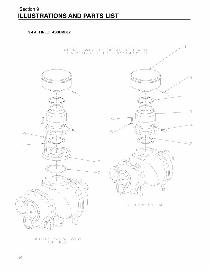
Section 9
ILLUSTRATIONS AND PARTS LIST
9.4 AIR INLET ASSEMBLY
40
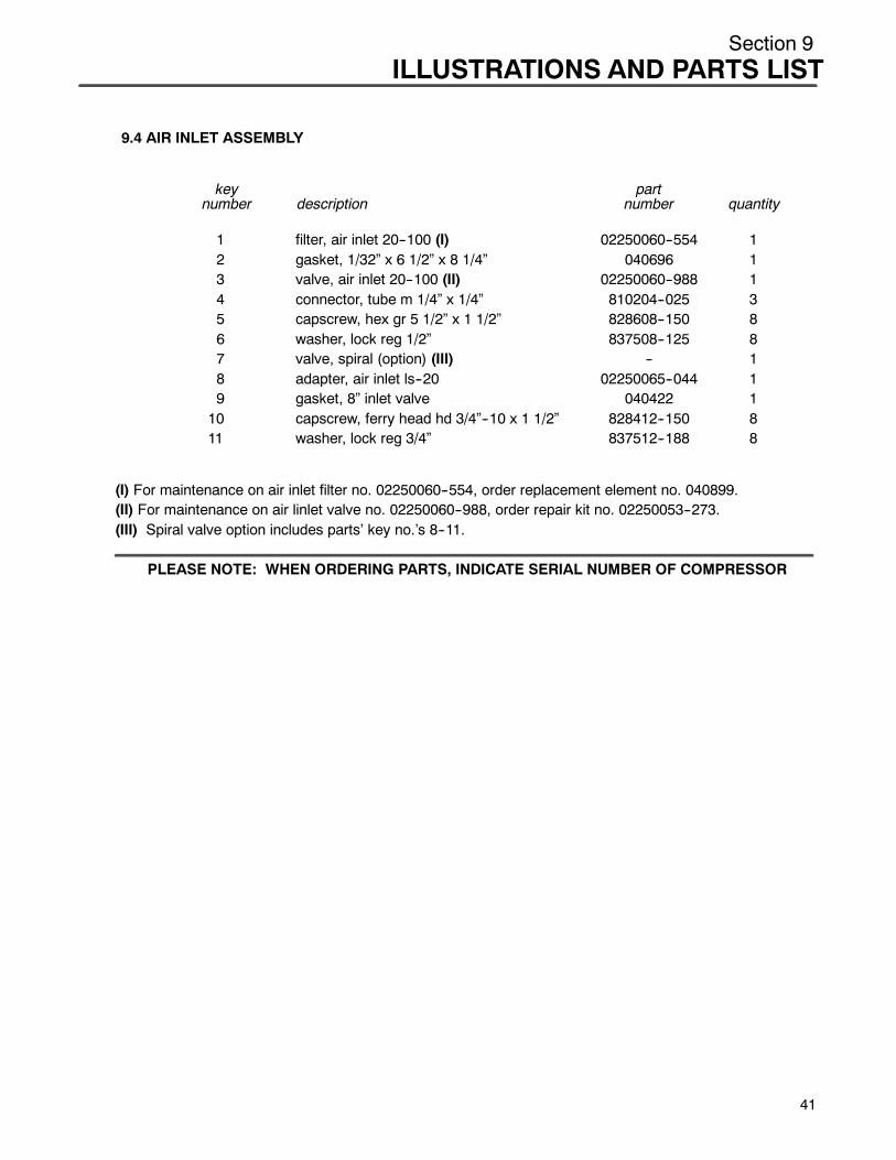
Section 9ILLUSTRATIONS AND PARTS LIST
9.4 AIR INLET ASSEMBLY
key partnumber description number quantity
1 filter, air inlet 20--100 (I) 02250060--554 12 gasket, 1/32” x 6 1/2” x 8 1/4” 040696 13 valve, air inlet 20--100 (II) 02250060--988 14 connector, tube m 1/4” x 1/4” 810204--025 35 capscrew, hex gr 5 1/2” x 1 1/2” 828608--150 86 washer, lock reg 1/2” 837508--125 87 valve, spiral (option) (III) -- 18 adapter, air inlet ls--20 02250065--044 19 gasket, 8” inlet valve 040422 110 capscrew, ferry head hd 3/4”--10 x 1 1/2” 828412--150 811 washer, lock reg 3/4” 837512--188 8
(I) For maintenance on air inlet filter no. 02250060--554, order replacement element no. 040899.(II) For maintenance on air linlet valve no. 02250060--988, order repair kit no. 02250053--273.(III) Spiral valve option includes parts’ key no.’s 8--11.
PLEASE NOTE: WHEN ORDERING PARTS, INDICATE SERIAL NUMBER OF COMPRESSOR
41
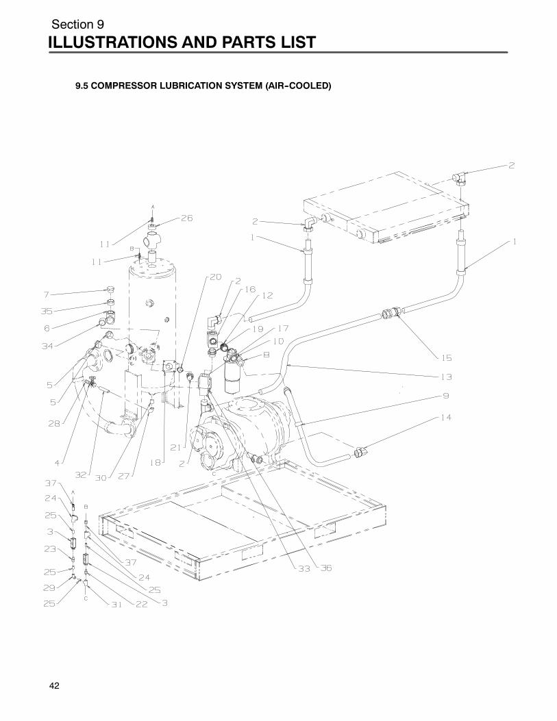
Section 9
ILLUSTRATIONS AND PARTS LIST
9.5 COMPRESSOR LUBRICATION SYSTEM (AIR--COOLED)
42
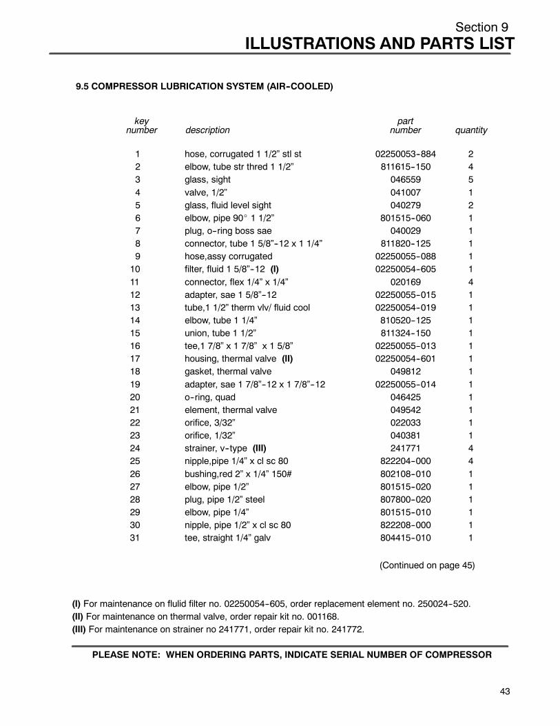
Section 9ILLUSTRATIONS AND PARTS LIST
9.5 COMPRESSOR LUBRICATION SYSTEM (AIR--COOLED)
key partnumber description number quantity
1 hose, corrugated 1 1/2” stl st 02250053--884 22 elbow, tube str thred 1 1/2” 811615--150 43 glass, sight 046559 54 valve, 1/2” 041007 15 glass, fluid level sight 040279 26 elbow, pipe 90_ 1 1/2” 801515--060 17 plug, o--ring boss sae 040029 18 connector, tube 1 5/8”--12 x 1 1/4” 811820--125 19 hose,assy corrugated 02250055--088 110 filter, fluid 1 5/8”--12 (I) 02250054--605 111 connector, flex 1/4” x 1/4” 020169 412 adapter, sae 1 5/8”--12 02250055--015 113 tube,1 1/2” therm vlv/ fluid cool 02250054--019 114 elbow, tube 1 1/4” 810520--125 115 union, tube 1 1/2” 811324--150 116 tee,1 7/8” x 1 7/8” x 1 5/8” 02250055--013 117 housing, thermal valve (II) 02250054--601 118 gasket, thermal valve 049812 119 adapter, sae 1 7/8”--12 x 1 7/8”--12 02250055--014 120 o--ring, quad 046425 121 element, thermal valve 049542 122 orifice, 3/32” 022033 123 orifice, 1/32” 040381 124 strainer, v--type (III) 241771 425 nipple,pipe 1/4” x cl sc 80 822204--000 426 bushing,red 2” x 1/4” 150# 802108--010 127 elbow, pipe 1/2” 801515--020 128 plug, pipe 1/2” steel 807800--020 129 elbow, pipe 1/4” 801515--010 130 nipple, pipe 1/2” x cl sc 80 822208--000 131 tee, straight 1/4” galv 804415--010 1
(Continued on page 45)
(I) For maintenance on flulid filter no. 02250054--605, order replacement element no. 250024--520.(II) For maintenance on thermal valve, order repair kit no. 001168.(III) For maintenance on strainer no 241771, order repair kit no. 241772.
PLEASE NOTE: WHEN ORDERING PARTS, INDICATE SERIAL NUMBER OF COMPRESSOR
43

Section 9
ILLUSTRATIONS AND PARTS LIST
44
9.5 COMPRESSOR LUBRICATION SYSTEM (AIR--COOLED)
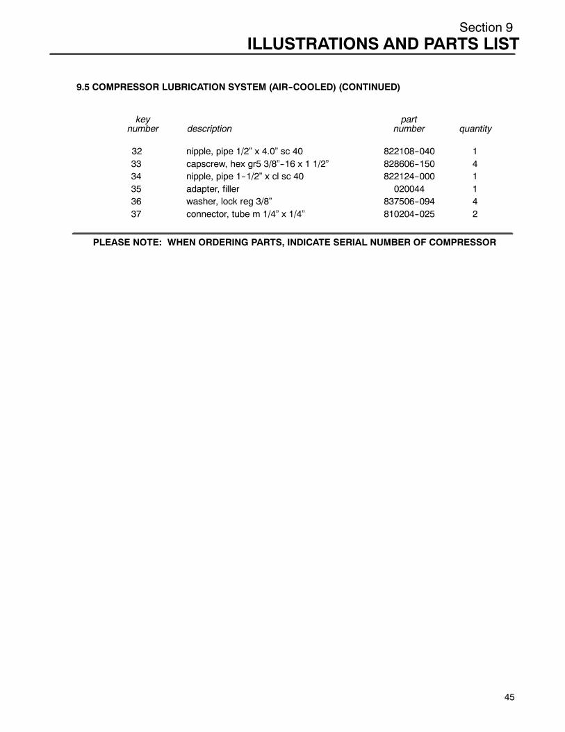
Section 9ILLUSTRATIONS AND PARTS LIST
9.5 COMPRESSOR LUBRICATION SYSTEM (AIR--COOLED) (CONTINUED)
key partnumber description number quantity
32 nipple, pipe 1/2” x 4.0” sc 40 822108--040 133 capscrew, hex gr5 3/8”--16 x 1 1/2” 828606--150 434 nipple, pipe 1--1/2” x cl sc 40 822124--000 135 adapter, filler 020044 136 washer, lock reg 3/8” 837506--094 437 connector, tube m 1/4” x 1/4” 810204--025 2
PLEASE NOTE: WHEN ORDERING PARTS, INDICATE SERIAL NUMBER OF COMPRESSOR
45

Section 9
ILLUSTRATIONS AND PARTS LIST
9.6 COMPRESSOR LUBRICATION SYSTEM WITH SPIRAL VALVE (AIR--COOLED)
46
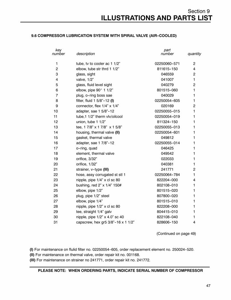
Section 9ILLUSTRATIONS AND PARTS LIST
9.6 COMPRESSOR LUBRICATION SYSTEM WITH SPIRAL VALVE (AIR--COOLED)
key partnumber description number quantity
1 tube, tv to cooler ac 1 1/2” 02250060--571 22 elbow, tube str thrd 1 1/2” 811615--150 43 glass, sight 046559 24 valve, 1/2” 041007 15 glass, fluid level sight 040279 26 elbow, pipe 90_ 1 1/2” 801515--060 17 plug, o--ring boss sae 040029 18 filter, fluid 1 5/8”--12 (I) 02250054--605 19 connector, flex 1/4” x 1/4” 020169 210 adapter, sae 1 5/8”--12 02250055--015 111 tube,1 1/2” therm vlv/oilcool 02250054--019 112 union, tube 1 1/2” 811324--150 113 tee, 1 7/8” x 1 7/8” x 1 5/8” 02250055--013 114 housing, thermal valve (II) 02250054--601 115 gasket, thermal valve 049812 116 adapter, sae 1 7/8”--12 02250055--014 117 o--ring, quad 046425 118 element, thermal valve 049542 119 orifice, 3/32” 022033 120 orifice, 1/32” 040381 121 strainer, v--type (III) 241771 222 hose, assy corrugated st stl 1 02250064--784 123 nipple, pipe 1/4” x cl sc 80 822204--000 424 bushing, red 2” x 1/4” 150# 802108--010 125 elbow, pipe 1/2” 801515--020 126 plug, pipe 1/2” steel 807800--020 127 elbow, pipe 1/4” 801515--010 128 nipple, pipe 1/2” x cl sc 80 822208--000 129 tee, straight 1/4” galv 804415--010 130 nipple, pipe 1/2” x 4.0” sc 40 822108--040 131 capscrew, hex gr5 3/8”--16 x 1 1/2” 828606--150 4
(Continued on page 49)
(I) For maintenance on flulid filter no. 02250054--605, order replacement element no. 250024--520.(II) For maintenance on thermal valve, order repair kit no. 001168.(III) For maintenance on strainer no 241771, order repair kit no. 241772.
PLEASE NOTE: WHEN ORDERING PARTS, INDICATE SERIAL NUMBER OF COMPRESSOR
47
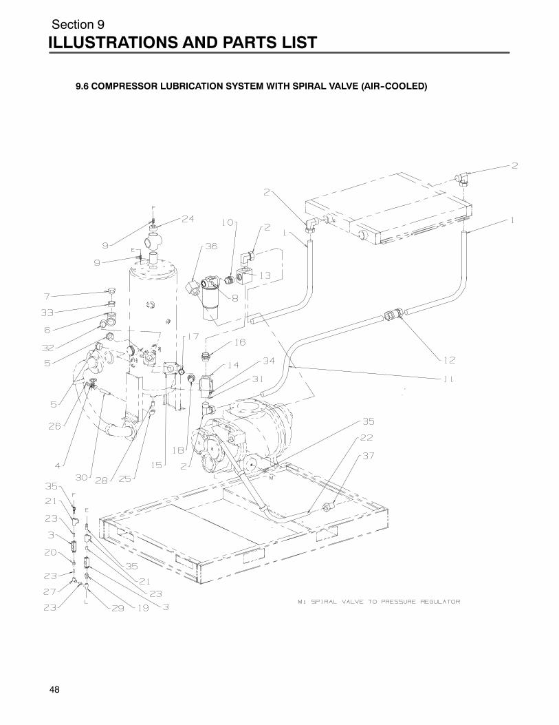
Section 9
ILLUSTRATIONS AND PARTS LIST
48
9.6 COMPRESSOR LUBRICATION SYSTEM WITH SPIRAL VALVE (AIR--COOLED)
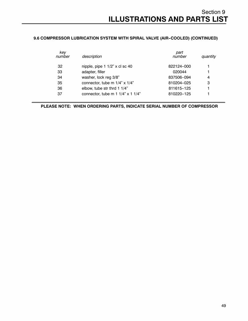
Section 9ILLUSTRATIONS AND PARTS LIST
9.6 COMPRESSOR LUBRICATION SYSTEM WITH SPIRAL VALVE (AIR--COOLED) (CONTINUED)
key partnumber description number quantity
32 nipple, pipe 1 1/2” x cl sc 40 822124--000 133 adapter, filler 020044 134 washer, lock reg 3/8” 837506--094 435 connector, tube m 1/4” x 1/4” 810204--025 336 elbow, tube str thrd 1 1/4” 811615--125 137 connector, tube m 1 1/4” x 1 1/4” 810220--125 1
PLEASE NOTE: WHEN ORDERING PARTS, INDICATE SERIAL NUMBER OF COMPRESSOR
49

Section 9
ILLUSTRATIONS AND PARTS LIST
9.7 COMPRESSOR LUBRICATION SYSTEM (WATER--COOLED)
50
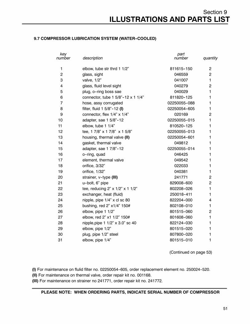
Section 9ILLUSTRATIONS AND PARTS LIST
9.7 COMPRESSOR LUBRICATION SYSTEM (WATER--COOLED)
key partnumber description number quantity
1 elbow, tube str thrd 1 1/2” 811615--150 22 glass, sight 046559 23 valve, 1/2” 041007 14 glass, fluid level sight 040279 25 plug, o--ring boss sae 040029 16 connector, tube 1 5/8”--12 x 1 1/4” 811820--125 17 hose, assy corrugated 02250055--088 18 filter, fluid 1 5/8”--12 (I) 02250054--605 19 connector, flex 1/4” x 1/4” 020169 210 adapter, sae 1 5/8”--12 02250055--015 111 elbow, tube 1 1/4” 810520--125 112 tee, 1 7/8” x 1 7/8” x 1 5/8” 02250055--013 113 housing, thermal valve (II) 02250054--601 114 gasket, thermal valve 049812 115 adapter, sae 1 7/8”--12 02250055--014 116 o--ring, quad 046425 117 element, thermal valve 049542 118 orifice, 3/32” 022033 119 orifice, 1/32” 040381 120 strainer, v--type (III) 241771 221 u--bolt, 6” pipe 829008--600 222 tee, reducing 2” x 1/2” x 1 1/2” 802208--026 123 exchanger, heat (fluid) 250018--411 124 nipple, pipe 1/4” x cl sc 80 822204--000 425 bushing, red 2” x1/4” 150# 802108--010 126 elbow, pipe 1 1/2” 801515--060 227 elbow, red 2” x1 1/2” 150# 801608--060 128 nipple,pipe 1 1/2” x 3.0” sc 40 822124--030 129 elbow, pipe 1/2” 801515--020 130 plug, pipe 1/2” steel 807800--020 131 elbow, pipe 1/4” 801515--010 1
(Continued on page 53)
(I) For maintenance on flulid filter no. 02250054--605, order replacement element no. 250024--520.(II) For maintenance on thermal valve, order repair kit no. 001168.(III) For maintenance on strainer no 241771, order repair kit no. 241772.
PLEASE NOTE: WHEN ORDERING PARTS, INDICATE SERIAL NUMBER OF COMPRESSOR
51

Section 9
ILLUSTRATIONS AND PARTS LIST
52
9.7 COMPRESSOR LUBRICATION SYSTEM (WATER--COOLED)
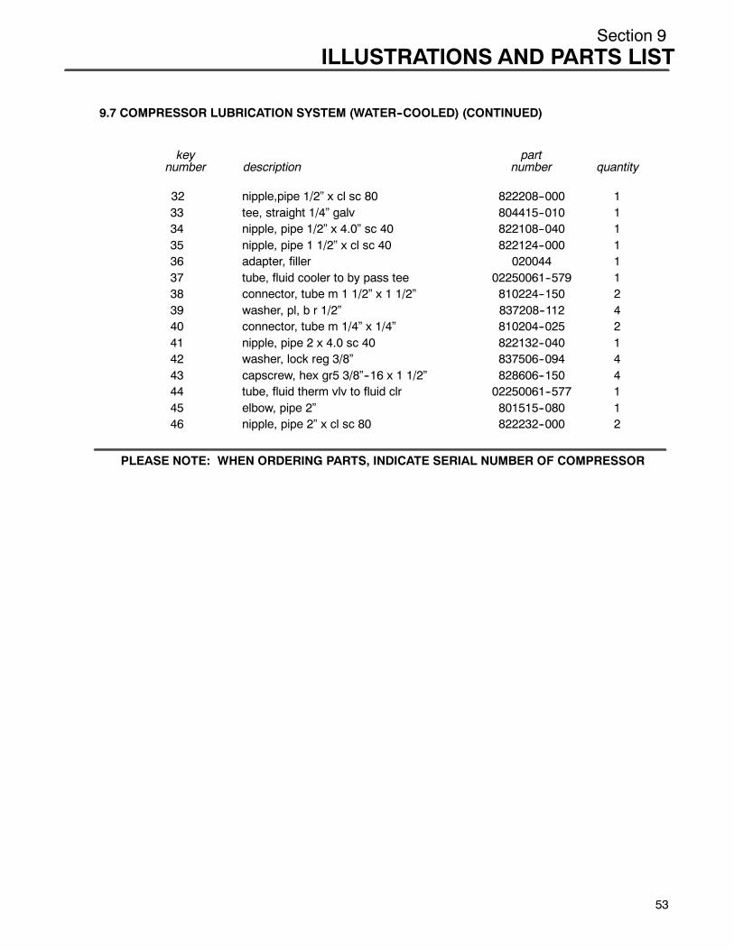
Section 9ILLUSTRATIONS AND PARTS LIST
9.7 COMPRESSOR LUBRICATION SYSTEM (WATER--COOLED) (CONTINUED)
key partnumber description number quantity
32 nipple,pipe 1/2” x cl sc 80 822208--000 133 tee, straight 1/4” galv 804415--010 134 nipple, pipe 1/2” x 4.0” sc 40 822108--040 135 nipple, pipe 1 1/2” x cl sc 40 822124--000 136 adapter, filler 020044 137 tube, fluid cooler to by pass tee 02250061--579 138 connector, tube m 1 1/2” x 1 1/2” 810224--150 239 washer, pl, b r 1/2” 837208--112 440 connector, tube m 1/4” x 1/4” 810204--025 241 nipple, pipe 2 x 4.0 sc 40 822132--040 142 washer, lock reg 3/8” 837506--094 443 capscrew, hex gr5 3/8”--16 x 1 1/2” 828606--150 444 tube, fluid therm vlv to fluid clr 02250061--577 145 elbow, pipe 2” 801515--080 146 nipple, pipe 2” x cl sc 80 822232--000 2
PLEASE NOTE: WHEN ORDERING PARTS, INDICATE SERIAL NUMBER OF COMPRESSOR
53
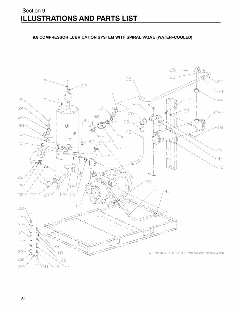
Section 9
ILLUSTRATIONS AND PARTS LIST
9.8 COMPRESSOR LUBRICATION SYSTEM WITH SPIRAL VALVE (WATER--COOLED)
54
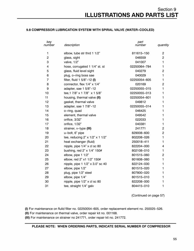
Section 9ILLUSTRATIONS AND PARTS LIST
9.8 COMPRESSOR LUBRICATION SYSTEM WITH SPIRAL VALVE (WATER--COOLED)
key partnumber description number quantity
1 elbow, tube str thrd 1 1/2” 811615--150 22 glass, sight 046559 23 valve, 1/2” 041007 14 hose, corrugated 1 1/4” st. st 02250064--784 15 glass, fluid level sight 040279 26 plug, o--ring boss sae 040029 17 filter, fluid 1 5/8”--12 (I) 02250054--605 18 connector, flex 1/4” x 1/4” 020169 29 adapter, sae 1 5/8”--12 02250055--015 110 tee,1 7/8” x 1 7/8” x 1 5/8” 02250055--013 111 housing, thermal valve (II) 02250054--601 112 gasket, thermal valve 049812 113 adapter, sae 1 7/8”--12 02250055--014 114 o--ring, quad 046425 115 element, thermal valve 049542 116 orifice, 3/32” 022033 117 orifice, 1/32” 040381 118 strainer, v--type (III) 241771 219 u--bolt, 6” pipe 829008--600 220 tee, reducing 2” x 1/2” x 1 1/2” 802208--026 121 heat exchanger (fluid) 250018--411 122 nipple, pipe 1/4” x cl sc 80 822204--000 423 bushing, red 2” x 1/4” 150# 802108--010 124 elbow, pipe 1 1/2” 801515--060 225 elbow, red 2” x1 1/2” 150# 801608--060 126 nipple, pipe 1 1/2” x 3.0” sc 40 822124--030 127 elbow, pipe 1/2” 801515--020 128 plug, pipe 1/2” steel 807800--020 129 elbow, pipe 1/4” 801515--010 130 nipple, pipe 1/2” x cl sc 80 822208--000 131 tee, straight 1/4” galv 804415--010 1
(Continued on page 57)
(I) For maintenance on flulid filter no. 02250054--605, order replacement element no. 250025--526.(II) For maintenance on thermal valve, order repair kit no. 001168.(III) For maintenance on strainer no 241771, order repair kit no. 241772.
PLEASE NOTE: WHEN ORDERING PARTS, INDICATE SERIAL NUMBER OF COMPRESSOR
55

Section 9
ILLUSTRATIONS AND PARTS LIST
56
9.8 COMPRESSOR LUBRICATION SYSTEM WITH SPIRAL VALVE (WATER--COOLED)
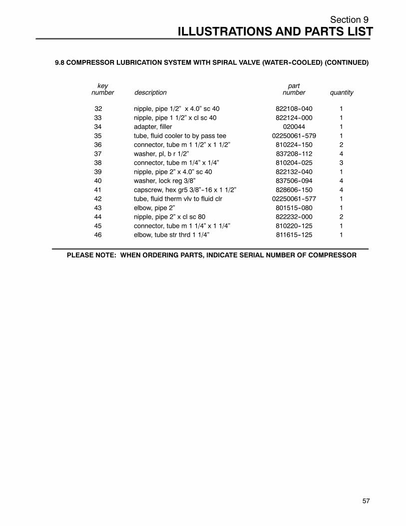
Section 9ILLUSTRATIONS AND PARTS LIST
9.8 COMPRESSOR LUBRICATION SYSTEM WITH SPIRAL VALVE (WATER--COOLED) (CONTINUED)
key partnumber description number quantity
32 nipple, pipe 1/2” x 4.0” sc 40 822108--040 133 nipple, pipe 1 1/2” x cl sc 40 822124--000 134 adapter, filler 020044 135 tube, fluid cooler to by pass tee 02250061--579 136 connector, tube m 1 1/2” x 1 1/2” 810224--150 237 washer, pl, b r 1/2” 837208--112 438 connector, tube m 1/4” x 1/4” 810204--025 339 nipple, pipe 2” x 4.0” sc 40 822132--040 140 washer, lock reg 3/8” 837506--094 441 capscrew, hex gr5 3/8”--16 x 1 1/2” 828606--150 442 tube, fluid therm vlv to fluid clr 02250061--577 143 elbow, pipe 2” 801515--080 144 nipple, pipe 2” x cl sc 80 822232--000 245 connector, tube m 1 1/4” x 1 1/4” 810220--125 146 elbow, tube str thrd 1 1/4” 811615--125 1
PLEASE NOTE: WHEN ORDERING PARTS, INDICATE SERIAL NUMBER OF COMPRESSOR
57
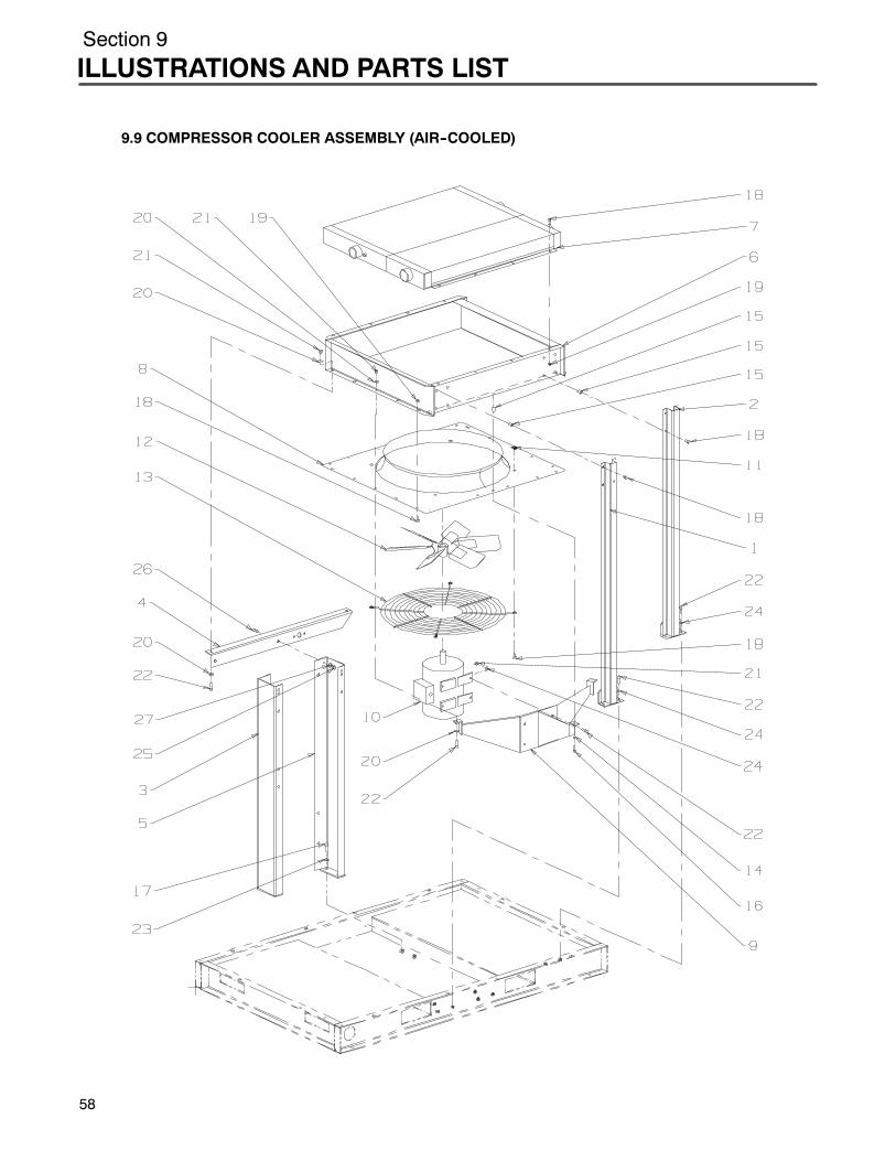
Section 9
ILLUSTRATIONS AND PARTS LIST
58
9.9 COMPRESSOR COOLER ASSEMBLY (AIR--COOLED)
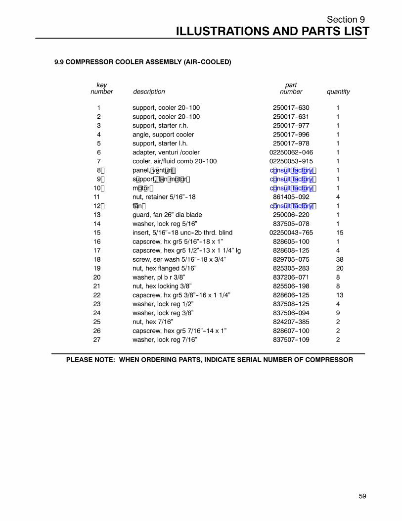
Section 9ILLUSTRATIONS AND PARTS LIST
9.9 COMPRESSOR COOLER ASSEMBLY (AIR--COOLED)
key partnumber description number quantity
1 support, cooler 20--100 250017--630 12 support, cooler 20--100 250017--631 13 support, starter r.h. 250017--977 14 angle, support cooler 250017--996 15 support, starter l.h. 250017--978 16 adapter, venturi /cooler 02250062--046 17 cooler, air/fluid comb 20--100 02250053--915 18 panel, v ent ur i c ons ult f ac t or y 19 s uppor t , f an m ot or c ons ult f ac t or y 110 m ot or c ons ult f ac t or y 111 nut, retainer 5/16”--18 861405--092 412 f an c ons ult f ac t or y 113 guard, fan 26” dia blade 250006--220 114 washer, lock reg 5/16” 837505--078 115 insert, 5/16”--18 unc--2b thrd. blind 02250043--765 1516 capscrew, hx gr5 5/16”--18 x 1” 828605--100 117 capscrew, hex gr5 1/2”--13 x 1 1/4” lg 828608--125 418 screw, ser wash 5/16”--18 x 3/4” 829705--075 3819 nut, hex flanged 5/16” 825305--283 2020 washer, pl b r 3/8” 837206--071 821 nut, hex locking 3/8” 825506--198 822 capscrew, hx gr5 3/8”--16 x 1 1/4” 828606--125 1323 washer, lock reg 1/2” 837508--125 424 washer, lock reg 3/8” 837506--094 925 nut, hex 7/16” 824207--385 226 capscrew, hex gr5 7/16”--14 x 1” 828607--100 227 washer, lock reg 7/16” 837507--109 2
PLEASE NOTE: WHEN ORDERING PARTS, INDICATE SERIAL NUMBER OF COMPRESSOR
59
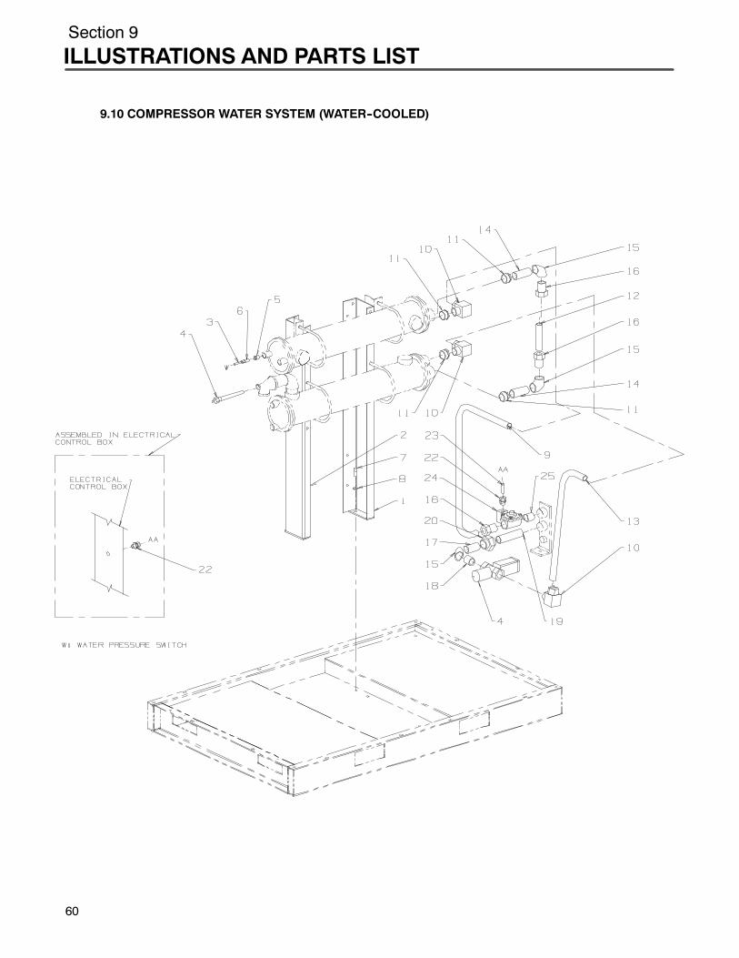
Section 9
ILLUSTRATIONS AND PARTS LIST
9.10 COMPRESSOR WATER SYSTEM (WATER--COOLED)
60
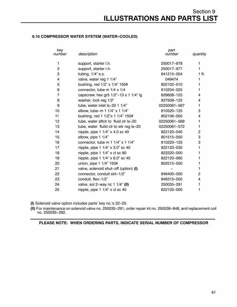
Section 9ILLUSTRATIONS AND PARTS LIST
9.10 COMPRESSOR WATER SYSTEM (WATER--COOLED)
key partnumber description number quantity
1 support, starter l.h. 250017--978 12 support, starter r.h. 250017--977 13 tubing, 1/4” s.s. 841215--004 1 ft.4 valve, water reg 1 1/4” 049474 15 bushing, red 1/2” x 1/4” 150# 802102--010 16 connector, tube m 1/4 x 1/4 810204--025 17 capscrew, hex gr5 1/2”--13 x 1 1/4” lg 828608--125 48 washer, lock reg 1/2” 837508--125 49 tube, water inlet ls--20 1 1/4” 02250061--567 110 elbow, tube--m 1 1/4” x 1 1/4” 810520--125 311 bushing, red 1 1/2”x 1 1/4” 150# 802106--050 412 tube, water aftclr to fluid clr ls--20 02250061--569 113 tube, water flulid clr to wtr reg ls--20 02250061--572 114 nipple, pipe 1 1/4” x 4.0 sc 40 822120--040 215 elbow, pipe 1 1/4” 801515--050 316 connector, tube m 1 1/4” x 1 1/4” 810220--125 317 nipple, pipe 1 1/4” x 3.0” sc 40 822120--030 118 nipple, pipe 1 1/4” x cl sc 80 822220--000 119 nipple, pipe 1 1/4” x 6.0” sc 40 822120--060 120 union, pipe 1 1/4” 150# 802515--050 121 valve, solenoid shut--off (option) (I) -- 122 connector, conduit strt--1/2” 846400--050 223 conduit, flex--1/2” 846315--050 424 valve, sol 2--way nc 1 1/4” (II) 250035--291 125 nipple, pipe 1 1/4” x cl sc 40 822120--000 1
(I) Solenoid valve option includes parts’ key no.’s 22--25.(II) For maintenance on solenoid valve no. 250035--291, order repair kit no. 250038--848, and replacement coil
no. 250035--292.
PLEASE NOTE: WHEN ORDERING PARTS, INDICATE SERIAL NUMBER OF COMPRESSOR
61
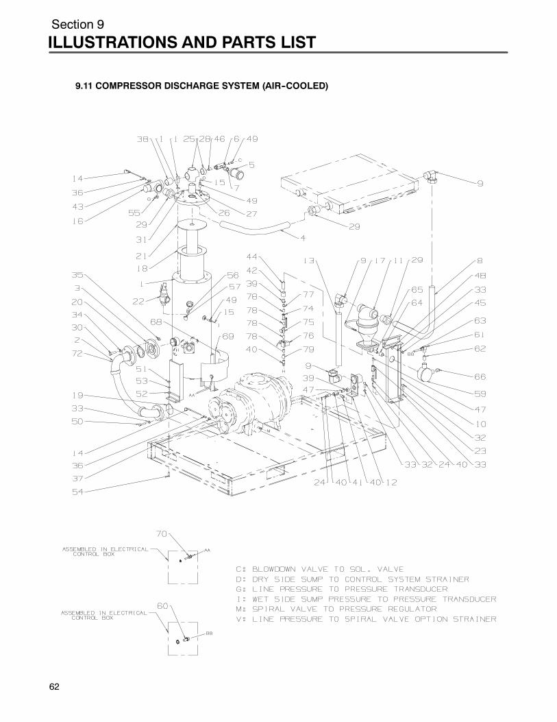
Section 9
ILLUSTRATIONS AND PARTS LIST
62
9.11 COMPRESSOR DISCHARGE SYSTEM (AIR--COOLED)

Section 9ILLUSTRATIONS AND PARTS LIST
9.11 COMPRESSOR DISCHARGE SYSTEM (AIR--COOLED)
key partnumber description number quantity
1 tank, air fluid sep 14” 02250054--125 12 hose, corrugated st stl 3” 02250059--184 13 flange, threaded 2 1/2” 819315--040 14 tube, 2” mpv to cooler 02250053--700 15 silencer, air 1/2” 041006 16 valve, blowdown 2--way pneu (I) 250030--276 17 orifice, 1/2”m x 1/2”f .156 234125--156 18 tube, air clr/sep 2” 02250053--698 19 elbow, tube 2” x 2” 90_ 810532--200 310 support, sep./trap combination 02250053--355 111 sep/trap, combination (II) 410143 112 support, brk cust. conn. 02250054--613 113 tube, sep/trap 2” to cust. conn. 02250053--869 114 probe, rtd 100ohm 250039--909 215 tubing, stl steel 1/4” 841215--004 15 ft.16 valve, 2” npt min press check 242405 117 u--bolt 6” 829008--600 118 separator, air/fluid prim (III) 02250060--462 119 o--ring, viton 3/4” x 1/8” 826502--240 120 gasket, asa 2 1/2” 150# 240621--7 121 separator, air/flulid second (III) 02250060--463 122 valve, relief 500 cfm 02250055--464 123 valve, ball 3/8” 047116 124 tubing, thermoplastic 3/8” 0d 250024--746 425 cross, pipe 150# 2” 801315--080 126 nipple, pipe 2” x 2 1/2” sc 40 822132--025 127 plug, pipe 1/2” steel 807800--020 128 bushing, red 2” x 1/2” 150# 802108--020 129 connector, tube m 2” x 2” 810232--200 330 capscr, hex gr5 5/8”--11 x 2 3/4” 828610--275 431 plug, pipe 1/4” steel 807800--010 1
(Continued on page 65)
(I) For maintenance on blowdown valve no. 250030--276, order repair kit no. 02250045--132.(II) For maintenance on separator/trap no. 410143, order repair kit no. 250033--038.(III) For separator maintenance, order replacement element kits no. 02250061--137 (primary), and no.
02250061--138 (secondary).
PLEASE NOTE: WHEN ORDERING PARTS, INDICATE SERIAL NUMBER OF COMPRESSOR
63

Section 9
ILLUSTRATIONS AND PARTS LIST
64
9.11 COMPRESSOR DISCHARGE SYSTEM (AIR--COOLED)
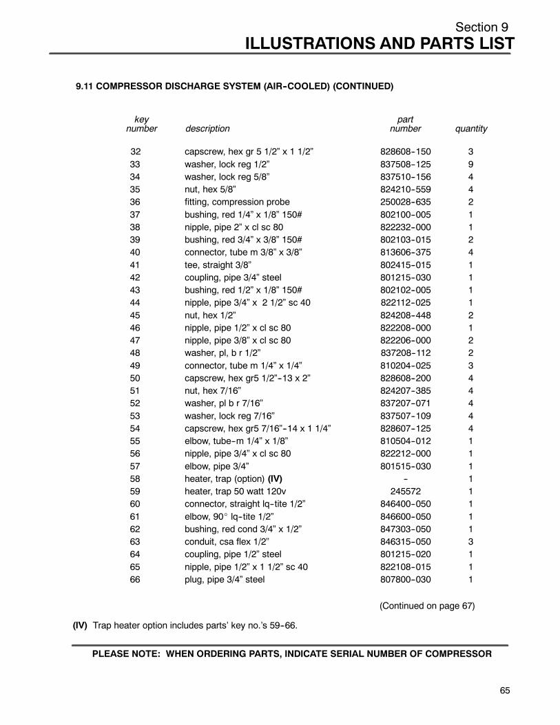
Section 9ILLUSTRATIONS AND PARTS LIST
9.11 COMPRESSOR DISCHARGE SYSTEM (AIR--COOLED) (CONTINUED)
key partnumber description number quantity
32 capscrew, hex gr 5 1/2” x 1 1/2” 828608--150 333 washer, lock reg 1/2” 837508--125 934 washer, lock reg 5/8” 837510--156 435 nut, hex 5/8” 824210--559 436 fitting, compression probe 250028--635 237 bushing, red 1/4” x 1/8” 150# 802100--005 138 nipple, pipe 2” x cl sc 80 822232--000 139 bushing, red 3/4” x 3/8” 150# 802103--015 240 connector, tube m 3/8” x 3/8” 813606--375 441 tee, straight 3/8” 802415--015 142 coupling, pipe 3/4” steel 801215--030 143 bushing, red 1/2” x 1/8” 150# 802102--005 144 nipple, pipe 3/4” x 2 1/2” sc 40 822112--025 145 nut, hex 1/2” 824208--448 246 nipple, pipe 1/2” x cl sc 80 822208--000 147 nipple, pipe 3/8” x cl sc 80 822206--000 248 washer, pl, b r 1/2” 837208--112 249 connector, tube m 1/4” x 1/4” 810204--025 350 capscrew, hex gr5 1/2”--13 x 2” 828608--200 451 nut, hex 7/16” 824207--385 452 washer, pl b r 7/16” 837207--071 453 washer, lock reg 7/16” 837507--109 454 capscrew, hex gr5 7/16”--14 x 1 1/4” 828607--125 455 elbow, tube--m 1/4” x 1/8” 810504--012 156 nipple, pipe 3/4” x cl sc 80 822212--000 157 elbow, pipe 3/4” 801515--030 158 heater, trap (option) (IV) -- 159 heater, trap 50 watt 120v 245572 160 connector, straight lq--tite 1/2” 846400--050 161 elbow, 90_ lq--tite 1/2” 846600--050 162 bushing, red cond 3/4” x 1/2” 847303--050 163 conduit, csa flex 1/2” 846315--050 364 coupling, pipe 1/2” steel 801215--020 165 nipple, pipe 1/2” x 1 1/2” sc 40 822108--015 166 plug, pipe 3/4” steel 807800--030 1
(Continued on page 67)
(IV) Trap heater option includes parts’ key no.’s 59--66.
PLEASE NOTE: WHEN ORDERING PARTS, INDICATE SERIAL NUMBER OF COMPRESSOR
65

Section 9
ILLUSTRATIONS AND PARTS LIST
66
9.11 COMPRESSOR DISCHARGE SYSTEM (AIR--COOLED)

Section 9ILLUSTRATIONS AND PARTS LIST
9.11 COMPRESSOR DISCHARGE SYSTEM (AIR--COOLED) (CONTINUED)
key partnumber description number quantity
67 heater, sump (option) (V) -- 168 adhesive, rtv108 4.7 oz tube (VI) 02250054--398 169 heater, sump 120v 02250069--938 170 connector, cord .31 cable 241585 171 valve, spiral (option) (VII) -- 172 hose, corrugated st stl 3” 02250064--754 173 drain, electric condensate (option) (VIII) -- 174 valve, ball 1/4” 047115 175 strainer, v--type 300psi (IX) 241771 176 valve, sol--1/4” w/ timer 120v (X) 250038--163 177 bushing, red 3/8” x1/4” 150# 802101--010 178 nipple, pipe 1/4” x cl sc 80 822204--000 479 coupling, red 3/8” x 1/4” 150# 801003--002 1
(V) Sump heater option includes parts’ key no.’s 68--70.
(VI) Apply adhesive to mating surface of heater before installing on tank.
(VII) Spiral valve option includes parts’ key no.’s 72 and 73.
(VIII) Electric condensate drain option includes parts’ key no.’s 74--79.
(IX) For maintenance on strainer no. 241771, order repair kit no. 241772.
(X) For maintenance on solenoid valve no. 250038--163, order replacement solenoid no. 250031--322,replacement valve no. 250031--278, and replacement timer 250038--164.
PLEASE NOTE: WHEN ORDERING PARTS, INDICATE SERIAL NUMBER OF COMPRESSOR
67
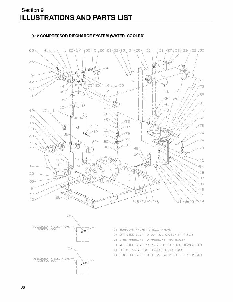
Section 9
ILLUSTRATIONS AND PARTS LIST
68
9.12 COMPRESSOR DISCHARGE SYSTEM (WATER--COOLED)

Section 9ILLUSTRATIONS AND PARTS LIST
9.12 COMPRESSOR DISCHARGE SYSTEM (WATER--COOLED)
key partnumber description number quantity
1 tank, air fluid sep 14” 02250054--125 12 hose, corrugated st stl 3” 02250059--184 13 flange, threaded 2 1/2” 819315--040 14 silencer, air 1/2” 041006 15 valve, blowdown 2--way pneu (I) 250030--276 16 orifice, 1/2”m x 1/2”f .156 234125--156 17 support, sep/trap combo 02250053--355 18 sep/trap, combination (II) 410143 19 probe, rtd 100ohm 250039--909 210 tubing, stl steel 1/4” 841215--004 15 ft.11 valve, 2” npt min press check 242405 112 u--bolt 6” 829008--600 313 separator, air/fluid prim (III) 02250060--462 114 o--ring, 3 3/4” x 1/8” 826502--240 115 gasket, asa 2 1/2” 150# 240621--7 116 separator, air/fluid second (III) 02250060--463 117 valve, relief 500cfm 02250055--464 118 valve, ball 3/8” 047116 119 tubing, thermoplastic 3/8” od 250024--746 420 support, bracket aftclr ls--20 02250061--876 221 support, bracket water in/out cust con 02250061--758 122 heat exchanger, aftercooler 043008 123 cross, pipe 150# 2” 801315--080 124 nipple, pipe 2” x 2 1/2” sc 40 822132--025 125 plug, pipe 1/2” steel 807800--020 126 connector, tube m 1/4” x 1/4” 810204--025 427 bushing, red 2” x 1/2” 150# 802108--020 128 capscr, hex gr5 5/8”--11 x 2 3/4” 828610--275 429 capscrew, hx gr 5 3/8” x 1 1/4” 828606--125 430 nut, hex 3/8” 824206--337 431 washer, lock reg 3/8” 837506--094 4
(Continued on page 71)
(I) For maintenance on blowdown valve no. 250030--276, order repair kit no. 02250045--132.(II) For maintenance on separator/trap no. 410143, order repair kit no. 250033--038.(III) For separator maintenance, order replacement element kits no. 02250061--137 (primary), and no.
02250061--138 (secondary).
PLEASE NOTE: WHEN ORDERING PARTS, INDICATE SERIAL NUMBER OF COMPRESSOR
69

Section 9
ILLUSTRATIONS AND PARTS LIST
70
9.12 COMPRESSOR DISCHARGE SYSTEM (WATER--COOLED)
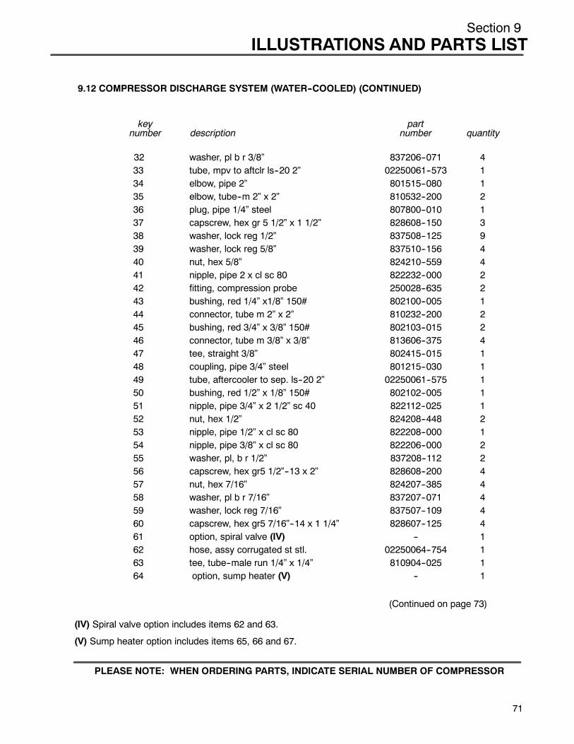
Section 9ILLUSTRATIONS AND PARTS LIST
9.12 COMPRESSOR DISCHARGE SYSTEM (WATER--COOLED) (CONTINUED)
key partnumber description number quantity
32 washer, pl b r 3/8” 837206--071 433 tube, mpv to aftclr ls--20 2” 02250061--573 134 elbow, pipe 2” 801515--080 135 elbow, tube--m 2” x 2” 810532--200 236 plug, pipe 1/4” steel 807800--010 137 capscrew, hex gr 5 1/2” x 1 1/2” 828608--150 338 washer, lock reg 1/2” 837508--125 939 washer, lock reg 5/8” 837510--156 440 nut, hex 5/8” 824210--559 441 nipple, pipe 2 x cl sc 80 822232--000 242 fitting, compression probe 250028--635 243 bushing, red 1/4” x1/8” 150# 802100--005 144 connector, tube m 2” x 2” 810232--200 245 bushing, red 3/4” x 3/8” 150# 802103--015 246 connector, tube m 3/8” x 3/8” 813606--375 447 tee, straight 3/8” 802415--015 148 coupling, pipe 3/4” steel 801215--030 149 tube, aftercooler to sep. ls--20 2” 02250061--575 150 bushing, red 1/2” x 1/8” 150# 802102--005 151 nipple, pipe 3/4” x 2 1/2” sc 40 822112--025 152 nut, hex 1/2” 824208--448 253 nipple, pipe 1/2” x cl sc 80 822208--000 154 nipple, pipe 3/8” x cl sc 80 822206--000 255 washer, pl, b r 1/2” 837208--112 256 capscrew, hex gr5 1/2”--13 x 2” 828608--200 457 nut, hex 7/16” 824207--385 458 washer, pl b r 7/16” 837207--071 459 washer, lock reg 7/16” 837507--109 460 capscrew, hex gr5 7/16”--14 x 1 1/4” 828607--125 461 option, spiral valve (IV) -- 162 hose, assy corrugated st stl. 02250064--754 163 tee, tube--male run 1/4” x 1/4” 810904--025 164 option, sump heater (V) -- 1
(Continued on page 73)
(IV) Spiral valve option includes items 62 and 63.
(V) Sump heater option includes items 65, 66 and 67.
PLEASE NOTE: WHEN ORDERING PARTS, INDICATE SERIAL NUMBER OF COMPRESSOR
71
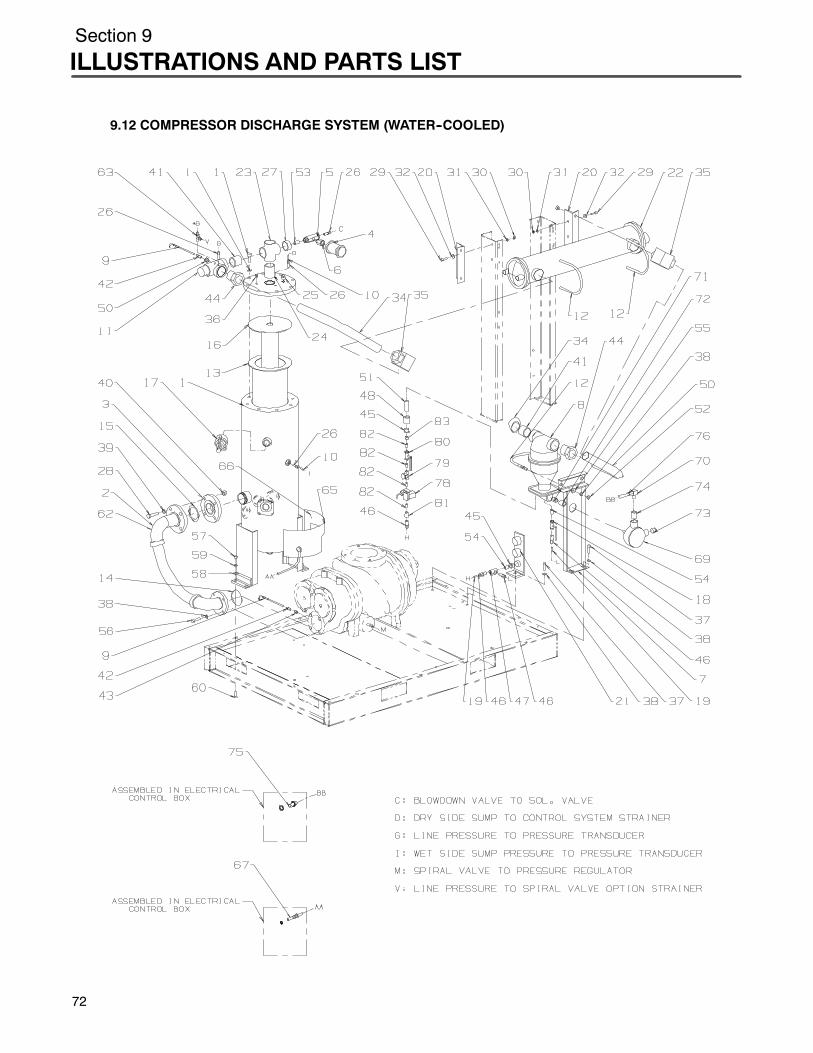
Section 9
ILLUSTRATIONS AND PARTS LIST
72
9.12 COMPRESSOR DISCHARGE SYSTEM (WATER--COOLED)
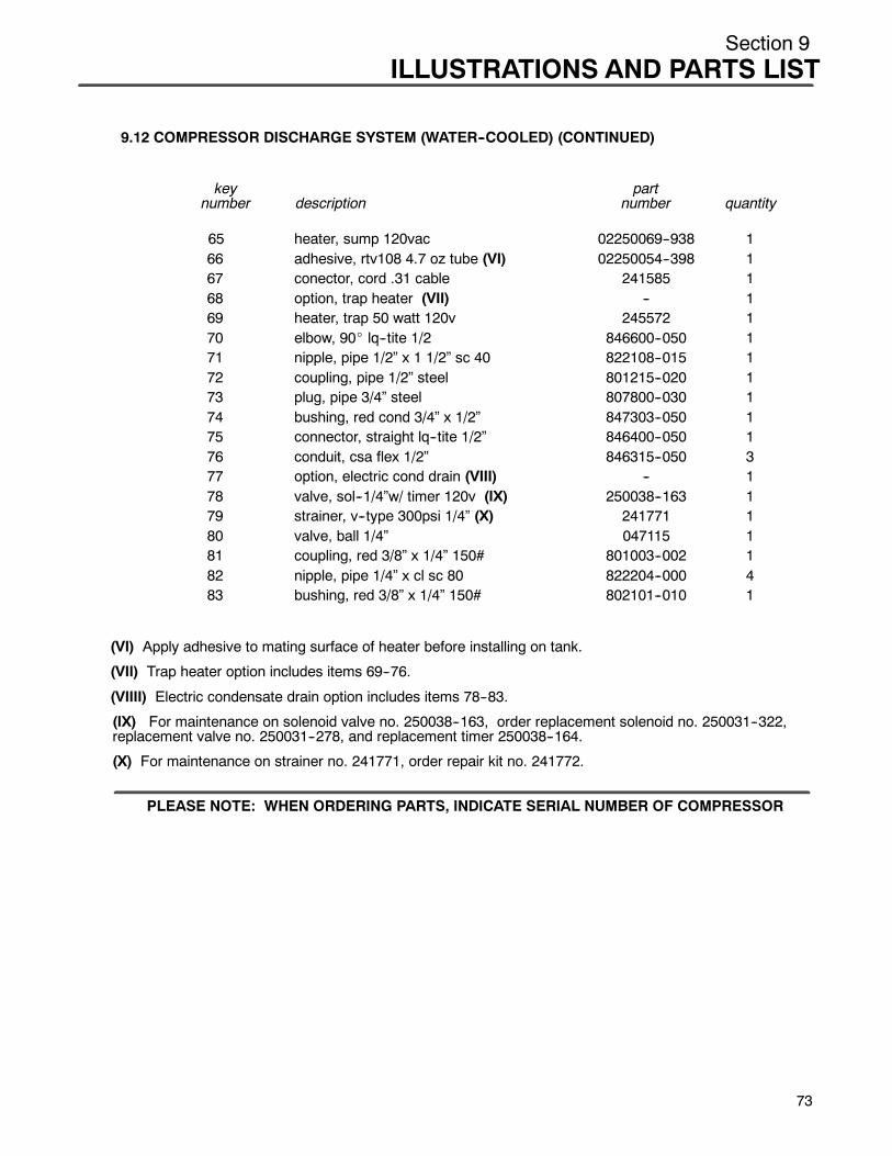
Section 9ILLUSTRATIONS AND PARTS LIST
9.12 COMPRESSOR DISCHARGE SYSTEM (WATER--COOLED) (CONTINUED)
key partnumber description number quantity
65 heater, sump 120vac 02250069--938 166 adhesive, rtv108 4.7 oz tube (VI) 02250054--398 167 conector, cord .31 cable 241585 168 option, trap heater (VII) -- 169 heater, trap 50 watt 120v 245572 170 elbow, 90_ lq--tite 1/2 846600--050 171 nipple, pipe 1/2” x 1 1/2” sc 40 822108--015 172 coupling, pipe 1/2” steel 801215--020 173 plug, pipe 3/4” steel 807800--030 174 bushing, red cond 3/4” x 1/2” 847303--050 175 connector, straight lq--tite 1/2” 846400--050 176 conduit, csa flex 1/2” 846315--050 377 option, electric cond drain (VIII) -- 178 valve, sol--1/4”w/ timer 120v (IX) 250038--163 179 strainer, v--type 300psi 1/4” (X) 241771 180 valve, ball 1/4” 047115 181 coupling, red 3/8” x 1/4” 150# 801003--002 182 nipple, pipe 1/4” x cl sc 80 822204--000 483 bushing, red 3/8” x 1/4” 150# 802101--010 1
(VI) Apply adhesive to mating surface of heater before installing on tank.
(VII) Trap heater option includes items 69--76.
(VIIII) Electric condensate drain option includes items 78--83.
(IX) For maintenance on solenoid valve no. 250038--163, order replacement solenoid no. 250031--322,replacement valve no. 250031--278, and replacement timer 250038--164.
(X) For maintenance on strainer no. 241771, order repair kit no. 241772.
PLEASE NOTE: WHEN ORDERING PARTS, INDICATE SERIAL NUMBER OF COMPRESSOR
73
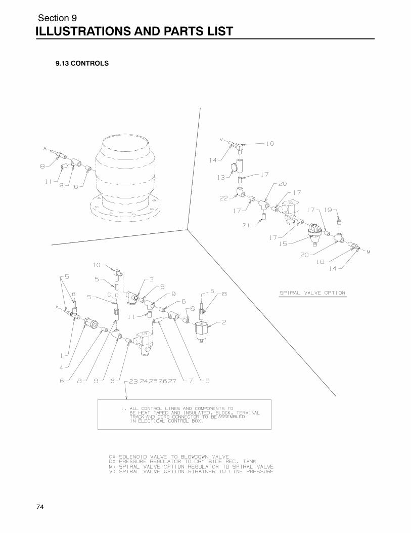
Section 9
ILLUSTRATIONS AND PARTS LIST
7
9.13 CONTROLS
4

Section 9ILLUSTRATIONS AND PARTS LIST
9.13 CONTROLS
key partnumber description number quantity
1 tee, tube m--run 1/4” 810904--025 12 valve, pressure regulator (I) 250017--280 13 strainer, v--type (II) 241771 14 valve, check 1/4” 049905 15 tubing, stainless steel 1/4” 841215--004 126 nipple, pipe 1/4” x cl s.s. 02250052--363 67 nipple, pipe 1/4” x 1 1/2” s.s. 250019--143 18 connector, tube m 1/4” x 1/4” 810204--025 39 tee, straight 1/4” s.s. 250000--060 410 elbow, tube--m 1/4” x 1/4” 810504--025 111 orifice, pipe plug 1/32” 232874 212 valve, spiral (option) (III) -- 113 strainer, v--type (II) 241771 114 tubing, stainless steel 1/4” 841215--004 815 valve, pressure regulator (IV) 408275 116 elbow, tube--m 1/4” x 1/4” 810504--025 117 nipple, pipe 1/4” x cl s.s. 02250052--363 518 connector, tube m 1/4” x 1/4” 810204--025 119 plug, pipe 1/4” steel 807800--010 120 tee, straight 1/4” s.s. 250000--060 221 orifice, pipe plug 1/32” 232874 122 elbow, pipe 1/4” swaglock 316s 250209--007 123 option, heat tracing (V) -- 124 connector, cord .31 cable 241585 125 insulation, pipe 7/8” 250022--693 5026 tape, heat self lim 120v 407403 2527 block, terminal & track 041493 1
(I) For maintenance on pressure regulator valve no. 250017--280, order repair kit no. 250019--453.(II) For maintenance on strainer no. 241771, order repair kit no. 241772.(III) Spiral valve option includes parts’ key no.’s 13--22.(IV) For maintenance on pressure regulator valve no. 408275, order repair kit no. 250028--693.(V) Heat tracing option includes parts’ key no.’s 24--27.
PLEASE NOTE: WHEN ORDERING PARTS, INDICATE SERIAL NUMBER OF COMPRESSOR
75

Section 9
ILLUSTRATIONS AND PARTS LIST
7
9.14 ELECTRIC CONTROL SYSTEM (AIR--COOLED)
6
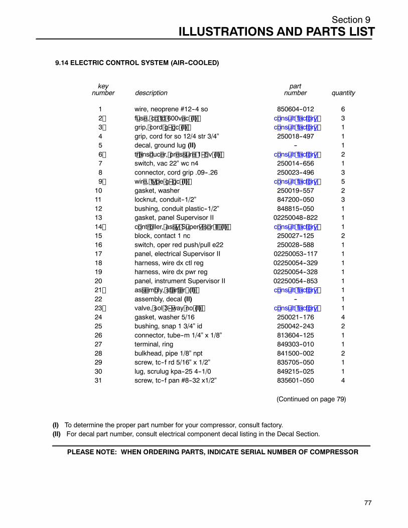
Section 9ILLUSTRATIONS AND PARTS LIST
9.14 ELECTRIC CONTROL SYSTEM (AIR--COOLED)
key partnumber description number quantity
1 wire, neoprene #12--4 so 850604--012 62 f us e, c c t d 600v ac (I ) c ons ult f ac t or y 33 grip, cord g -- gc (I ) c ons ult f ac t or y 14 grip, cord for so 12/4 str 3/4” 250018--497 15 decal, ground lug (II) -- 16 t r ans duc er, pr es s ur e 1 -- 5v (I ) c ons ult f ac t or y 27 switch, vac 22” wc n4 250014--656 18 connector, cord grip .09--.26 250023--496 39 wir e, t y pe g -- gc (I ) c ons ult f ac t or y 510 gasket, washer 250019--557 211 locknut, conduit--1/2” 847200--050 312 bushing, conduit plastic--1/2” 848815--050 113 gasket, panel Supervisor II 02250048--822 114 c ont r oller, as s y S uper v is or I I (I ) c ons ult f ac t or y 115 block, contact 1 nc 250027--125 216 switch, oper red push/pull e22 250028--588 117 panel, electrical Supervisor II 02250053--117 118 harness, wire dx ctl reg 02250054--329 119 harness, wire dx pwr reg 02250054--328 120 panel, instrument Supervisor II 02250054--853 121 as s em bly, s t ar t er (I ) c ons ult f ac t or y 122 assembly, decal (II) -- 123 valve, sol 3 -- way no (I ) c ons ult f ac t or y 124 gasket, washer 5/16 250021--176 425 bushing, snap 1 3/4” id 250042--243 226 connector, tube--m 1/4” x 1/8” 813604--125 127 terminal, ring 849303--010 128 bulkhead, pipe 1/8” npt 841500--002 229 screw, tc--f rd 5/16” x 1/2” 835705--050 130 lug, scrulug kpa--25 4--1/0 849215--025 131 screw, tc--f pan #8--32 x1/2” 835601--050 4
(Continued on page 79)
(I) To determine the proper part number for your compressor, consult factory.(II) For decal part number, consult electrical component decal listing in the Decal Section.
PLEASE NOTE: WHEN ORDERING PARTS, INDICATE SERIAL NUMBER OF COMPRESSOR
77
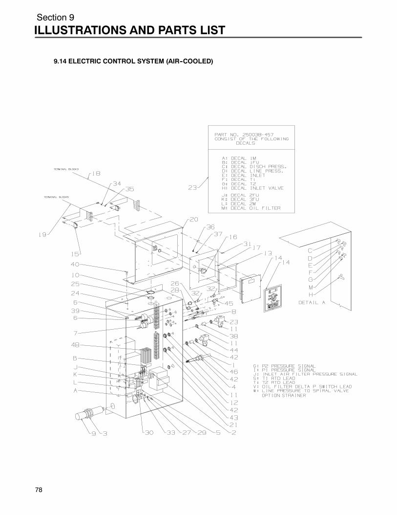
Section 9
ILLUSTRATIONS AND PARTS LIST
78
9.14 ELECTRIC CONTROL SYSTEM (AIR--COOLED)

Section 9ILLUSTRATIONS AND PARTS LIST
9.14 ELECTRIC CONTROL SYSTEM (AIR--COOLED) (CONTINUED)
key partnumber description number quantity
32 connector, tube m 1/4” x 1/8” 810204--012 233 lug, hylug 849106--002 234 nut, plated 5/16”--18 825205--273 135 washer, lock ext 5/16” 838405--034 136 nut, hex metric m4 x .7 825904--070 837 washer, springlck reg m4 838804--090 838 nipple, conduit 1/2” x close 250007--168 139 nut, hex flanged 5/16” 825305--283 440 screw, ser wash 5/16” x 3/4” 829705--075 441 valve, spiral (option) (III) -- 142 locknut, conduit--1/2” 847200--050 343 bushing, conduit plastic--1/2” 848815--050 144 v alv e, s ol 3 -- way no c ons ult f ac t or y 145 tee, tube--male run 1/4” x 1/8” 810904--012 146 nipple, conduit 1/2” x close 250007--168 147 option, heater enclosure htr_encl_opt 148 heater, enclosure 120v 30w 250010--253 1
(III) Spiral valve option includes parts’ key no.’s 42--48.
PLEASE NOTE: WHEN ORDERING PARTS, INDICATE SERIAL NUMBER OF COMPRESSOR
79

Section 9
ILLUSTRATIONS AND PARTS LIST
9.15 ELECTRIC CONTROL SYSTEM (WATER--COOLED)
80

Section 9ILLUSTRATIONS AND PARTS LIST
9.15 ELECTRIC CONTROL SYSTEM (WATER--COOLED)
key partnumber description number quantity
1 fuse, cc td 2a 600ac (I) various 32 grip, cord #1 (I) various 13 decal, ground lug 045433 14 transducer, pressure 0--200# 1--5v (I) various 25 valve, sol 3--way no 150p (II) 250038--674 16 switch, vac 22” wc n4 250014--656 17 connector, cord grip .09--.26 250023--496 38 wire, type g--gc 1ga (I) various 59 bracket, sol valve supt 250030--037 110 gasket, washer 250019--557 211 gasket, panel Supervisor II 02250048--822 112 controller, assy Supervisor II basic (I) various 113 block, contact 1 nc 250027--125 214 switch, oper red push/pull e22 250028--588 115 panel, electrical Supervisor II 02250054--854 116 harness, wire dx ctl reg 02250054--329 117 harness, wire dx pwr reg 02250054--328 118 panel, instrument Supervisor II 02250054--853 119 assembly, starter n4 mfv nc n12 sup (I) various 120 switch, low water pressure 250017--992 121 assembly, decal (III) -- 122 gasket, washer 5/16” 250021--176 423 bushing, snap 1 3/4” id 250042--243 224 connector, tube--m 1/4” x 1/8” 813604--125 125 terminal, ring 849303--010 126 bulkhead, pipe 1/8” npt 841500--002 227 connector, tube--m 1/4 x 1/8 810204--012 228 screw, tc--f rd 5/16” x 1/2” 835705--050 129 lug, scrulug kpa--25 4--1/0 849215--025 130 screw, tc--f pan 8”--32 x 3/8” 835601--038 231 screw, self tap 10--24 x 1/2” 835602--050 232 screw, tc--f pan #8--32 x1/2” 835601--050 8
(Continued on page 83)
(I) To determine the proper part number for your compressor, consult factory.(II) For maintenance on solenoid valve no. 250038--674, order repair kit no. 250038--673, and
replacement coil no. 250031--738.(III) For decal part number, consult electrical component decal listing in the Decal Section.
PLEASE NOTE: WHEN ORDERING PARTS, INDICATE SERIAL NUMBER OF COMPRESSOR
81
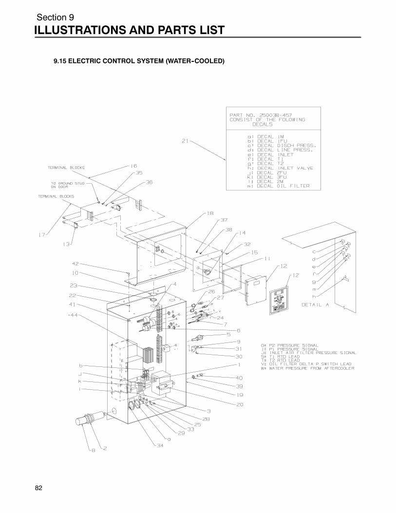
Section 9
ILLUSTRATIONS AND PARTS LIST
82
9.15 ELECTRIC CONTROL SYSTEM (WATER--COOLED)
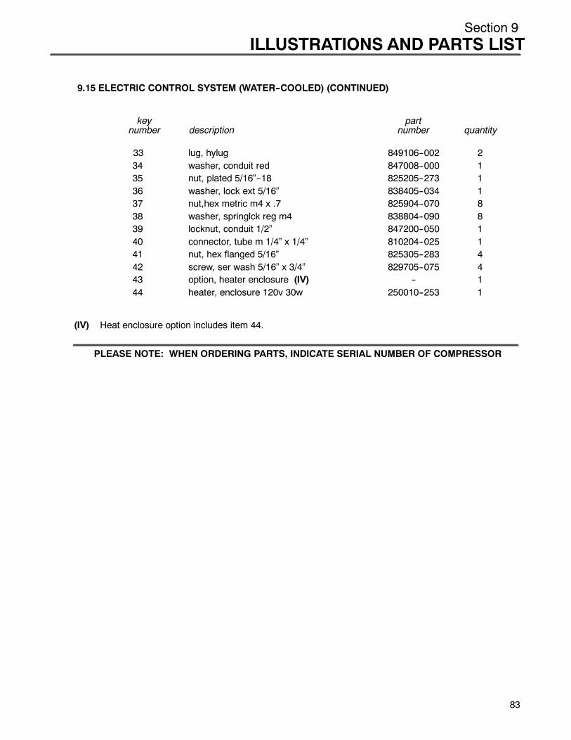
Section 9ILLUSTRATIONS AND PARTS LIST
9.15 ELECTRIC CONTROL SYSTEM (WATER--COOLED) (CONTINUED)
key partnumber description number quantity
33 lug, hylug 849106--002 234 washer, conduit red 847008--000 135 nut, plated 5/16”--18 825205--273 136 washer, lock ext 5/16” 838405--034 137 nut,hex metric m4 x .7 825904--070 838 washer, springlck reg m4 838804--090 839 locknut, conduit 1/2” 847200--050 140 connector, tube m 1/4” x 1/4” 810204--025 141 nut, hex flanged 5/16” 825305--283 442 screw, ser wash 5/16” x 3/4” 829705--075 443 option, heater enclosure (IV) -- 144 heater, enclosure 120v 30w 250010--253 1
(IV) Heat enclosure option includes item 44.
PLEASE NOTE: WHEN ORDERING PARTS, INDICATE SERIAL NUMBER OF COMPRESSOR
83

Section 9
ILLUSTRATIONS AND PARTS LIST
84
9.16 UNIT TUBING

Section 9ILLUSTRATIONS AND PARTS LIST
9.16 UNIT TUBING
key partnumber description number quantity
1 manifold, 1.25” x 1.25” out 02250045--432 12 connector, tube--M 3/8” x 1/4” 810206--025 53 tube, .38” 02250045--056 14 tube, .38” 02250045--057 15 elbow, tube--M 3/8” x 1/4” 810506--025 36 tube, .38” 02250044--276 17 elbow, tube--M 3/8” x 1/8” 810506--012 28 capscrew, hex gr 8 5/16”--18 x 3/4” 828205--705 49 orifice, 1/8”M x 1/4”F x .188” 220959 110 elbow, tube--M 3/4” x 1/2” 810512--050 211 elbow, pipe 90_ 1/2” 806530--020 112 nipple, pipe 1/2” x 2” 822208--020 113 orifice, 1/2” x 1/2”F x .313” 234125--313 114 bushing, reducing hex 1 1/4” x 1/2” 802105--020 115 tube, .38” 02250045--279 116 tube, .38” 02250045--060 117 tube, .38” 02250045--059 118 support 02250044--911 119 orifice, .062” x .25”M x .25”F 028831 220 capscrew, ferry hd 1/2”--13 x 1 828408--100 2
PLEASE NOTE: WHEN ORDERING PARTS, INDICATE SERIAL NUMBER OF COMPRESSOR
85

Section 9
ILLUSTRATIONS AND PARTS LIST
8
9.17 MOTOR ASSEMBLY
6

Section 9ILLUSTRATIONS AND PARTS LIST
9.17 MOTOR ASSEMBLY
key partnumber description number quantity
1 connector, wire yellow (460V) 851000--074 6Sconnector, wire yellow (575V) 851000--074 3
2 grip, cord for so 12/4 st 250018--495 13 screw, hex 5/16” x 1” (460V & 575V) 828605--100 64 lug, burndy 1/0 x 3/8” (460V) 849106--100 35 grip, cord #1 (460V) 250014--560 26 washer, conduit red 3 1/2” x 2” (460V) 847014--080 27 insulator, splice t & b msc 250006--113 38 nut, hex plated 5/16”--18 (230V) 824205--273 3
Snut, hex plated 5/16”--18 (460V & 575V) 824205--273 69 wire, type g--gc 1ga (460V) 250014--309 710 wire, neoprene #12--4 so 850604--012 611 terminal, ring 1/4” x 12ga 849304--010 112 lug, burndy ya2c--l #2--3/8” (575V) 849106--002 113 insulator, splice t & b msc (460V & 575V) 250006--112 314 washer, pl--b plated 5/16” (230V) 838205--071 6
Swasher, pl--b plated 5/16” (460V & 575V) 838205--071 1215 washer, springlock unfin 5/16” (230V) 837505--078 3
Swasher, springlock unfin 5/16”(460V & 575V) 837505--078 6
16 connector, wire red (230V) 891000--076 317 screw, hex 5/16” x 1 1/4” (230V) 828605--125 318 lug, burndy--hylug 350mcm x 1/2” (230V) 849108--035 319 wire, type g--gc 3ga (575V) 250014--307 720 wire, type g--gc 250mcm (230V) 250014--314 721 lug, burndy ya2c--l #2--5/16” (575V) 849105--002 322 washer, conduit reducing 3” x 1 1/2” (575V) 847012--060 223 washer, conduit reducing 3 1/2” x 2 1/2”
(230V) 847014--100 224 grip, cord #2 (575V) 250014--559 225 grip, cord #250mcm (230V) 250014--565 226 lug, burndy ya4--L4--4--3/8” (460V) 849106--004 127 lug, burndy ya2c--l #2--3/8” (230V) 849106--002 1
PLEASE NOTE: WHEN ORDERING PARTS, INDICATE SERIAL NUMBER OF COMPRESSOR
87

Section 9
ILLUSTRATIONS AND PARTS LIST
8
9.18 ENCLOSURE ASSEMBLY (AIR--COOLED)
8
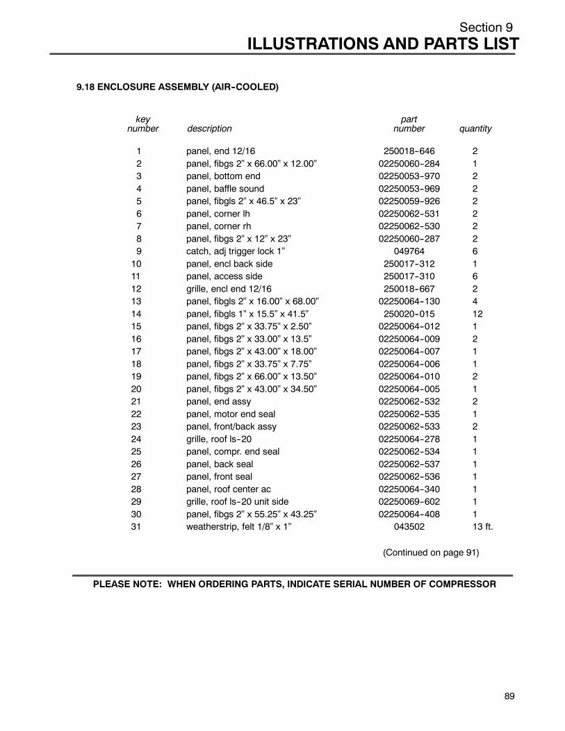
Section 9ILLUSTRATIONS AND PARTS LIST
9.18 ENCLOSURE ASSEMBLY (AIR--COOLED)
key partnumber description number quantity
1 panel, end 12/16 250018--646 22 panel, fibgs 2” x 66.00” x 12.00” 02250060--284 13 panel, bottom end 02250053--970 24 panel, baffle sound 02250053--969 25 panel, fibgls 2” x 46.5” x 23” 02250059--926 26 panel, corner lh 02250062--531 27 panel, corner rh 02250062--530 28 panel, fibgs 2” x 12” x 23” 02250060--287 29 catch, adj trigger lock 1” 049764 610 panel, encl back side 250017--312 111 panel, access side 250017--310 612 grille, encl end 12/16 250018--667 213 panel, fibgls 2” x 16.00” x 68.00” 02250064--130 414 panel, fibgls 1” x 15.5” x 41.5” 250020--015 1215 panel, fibgs 2” x 33.75” x 2.50” 02250064--012 116 panel, fibgs 2” x 33.00” x 13.5” 02250064--009 217 panel, fibgs 2” x 43.00” x 18.00” 02250064--007 118 panel, fibgs 2” x 33.75” x 7.75” 02250064--006 119 panel, fibgs 2” x 66.00” x 13.50” 02250064--010 220 panel, fibgs 2” x 43.00” x 34.50” 02250064--005 121 panel, end assy 02250062--532 222 panel, motor end seal 02250062--535 123 panel, front/back assy 02250062--533 224 grille, roof ls--20 02250064--278 125 panel, compr. end seal 02250062--534 126 panel, back seal 02250062--537 127 panel, front seal 02250062--536 128 panel, roof center ac 02250064--340 129 grille, roof ls--20 unit side 02250069--602 130 panel, fibgs 2” x 55.25” x 43.25” 02250064--408 131 weatherstrip, felt 1/8” x 1” 043502 13 ft.
(Continued on page 91)
PLEASE NOTE: WHEN ORDERING PARTS, INDICATE SERIAL NUMBER OF COMPRESSOR
89
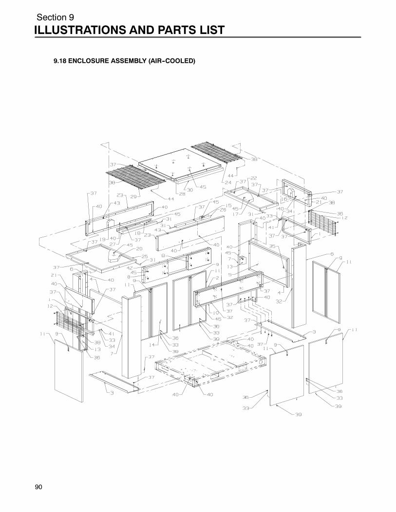
Section 9
ILLUSTRATIONS AND PARTS LIST
90
9.18 ENCLOSURE ASSEMBLY (AIR--COOLED)
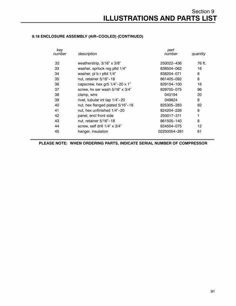
Section 9ILLUSTRATIONS AND PARTS LIST
9.18 ENCLOSURE ASSEMBLY (AIR--COOLED) (CONTINUED)
key partnumber description number quantity
32 weatherstrip, 3/16” x 3/8” 250022--436 76 ft.33 washer, sprlock reg pltd 1/4” 838504--062 1634 washer, pl b r pltd 1/4” 838204--071 835 nut, retainer 5/16”--18 861405--092 836 capscrew, hex gr5 1/4”--20 x 1” 829104--100 1637 screw, hx ser wash 5/16” x 3/4” 829705--075 9638 clamp, wire 043194 2039 rivet, tubular int tap 1/4”--20 049824 840 nut, hex flanged plated 5/16”--18 825305--283 8241 nut, hex unfinished 1/4”--20 824204--226 842 panel, encl front side 250017--311 143 nut, retainer 5/16”--18 861505--140 844 screw, self drill 1/4” x 3/4” 834504--075 1245 hanger, insulation 02250054--281 61
PLEASE NOTE: WHEN ORDERING PARTS, INDICATE SERIAL NUMBER OF COMPRESSOR
91
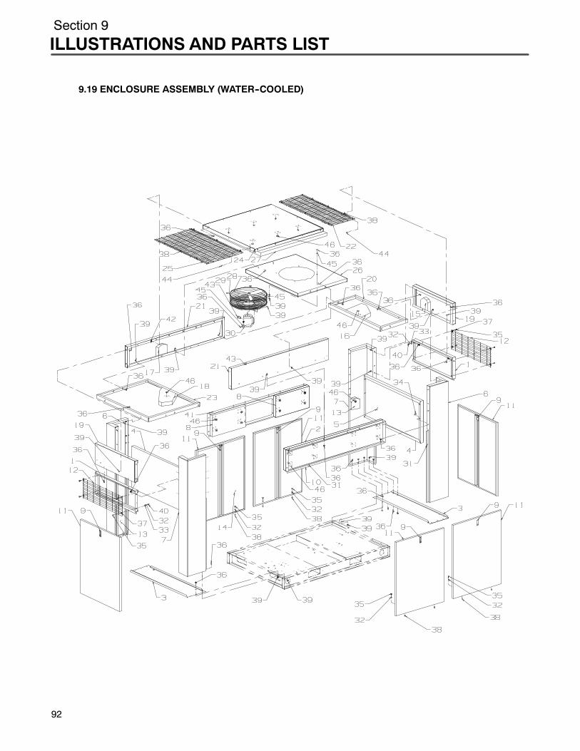
Section 9
ILLUSTRATIONS AND PARTS LIST
9.19 ENCLOSURE ASSEMBLY (WATER--COOLED)
92
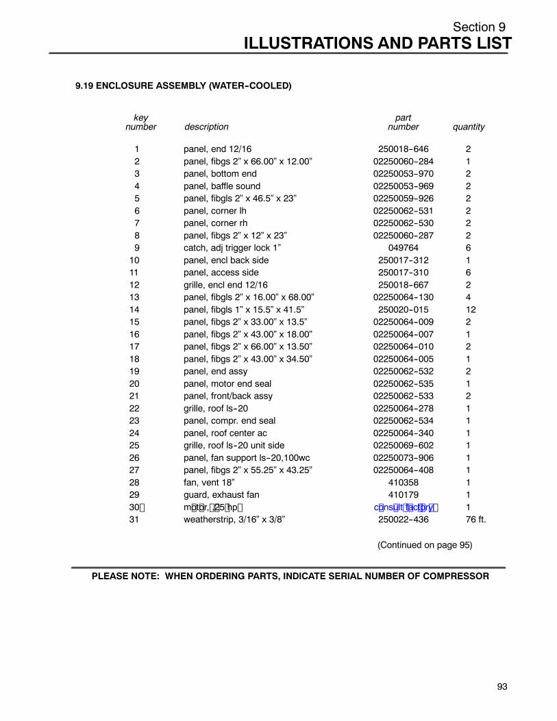
Section 9ILLUSTRATIONS AND PARTS LIST
9.19 ENCLOSURE ASSEMBLY (WATER--COOLED)
key partnumber description number quantity
1 panel, end 12/16 250018--646 22 panel, fibgs 2” x 66.00” x 12.00” 02250060--284 13 panel, bottom end 02250053--970 24 panel, baffle sound 02250053--969 25 panel, fibgls 2” x 46.5” x 23” 02250059--926 26 panel, corner lh 02250062--531 27 panel, corner rh 02250062--530 28 panel, fibgs 2” x 12” x 23” 02250060--287 29 catch, adj trigger lock 1” 049764 610 panel, encl back side 250017--312 111 panel, access side 250017--310 612 grille, encl end 12/16 250018--667 213 panel, fibgls 2” x 16.00” x 68.00” 02250064--130 414 panel, fibgls 1” x 15.5” x 41.5” 250020--015 1215 panel, fibgs 2” x 33.00” x 13.5” 02250064--009 216 panel, fibgs 2” x 43.00” x 18.00” 02250064--007 117 panel, fibgs 2” x 66.00” x 13.50” 02250064--010 218 panel, fibgs 2” x 43.00” x 34.50” 02250064--005 119 panel, end assy 02250062--532 220 panel, motor end seal 02250062--535 121 panel, front/back assy 02250062--533 222 grille, roof ls--20 02250064--278 123 panel, compr. end seal 02250062--534 124 panel, roof center ac 02250064--340 125 grille, roof ls--20 unit side 02250069--602 126 panel, fan support ls--20,100wc 02250073--906 127 panel, fibgs 2” x 55.25” x 43.25” 02250064--408 128 fan, vent 18” 410358 129 guard, exhaust fan 410179 130 m ot or, . 25 hp c ons ult f ac t or y 131 weatherstrip, 3/16” x 3/8” 250022--436 76 ft.
(Continued on page 95)
PLEASE NOTE: WHEN ORDERING PARTS, INDICATE SERIAL NUMBER OF COMPRESSOR
93

Section 9
ILLUSTRATIONS AND PARTS LIST
94
9.19 ENCLOSURE ASSEMBLY (WATER--COOLED)
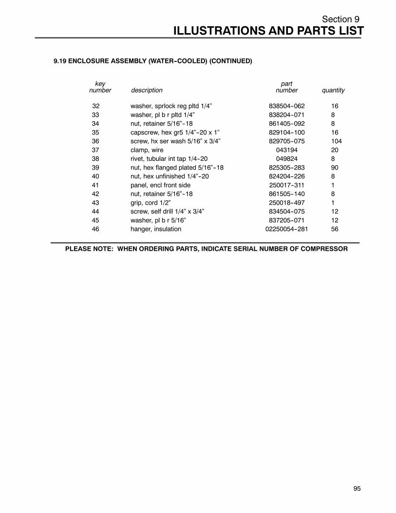
Section 9ILLUSTRATIONS AND PARTS LIST
9.19 ENCLOSURE ASSEMBLY (WATER--COOLED) (CONTINUED)
key partnumber description number quantity
32 washer, sprlock reg pltd 1/4” 838504--062 1633 washer, pl b r pltd 1/4” 838204--071 834 nut, retainer 5/16”--18 861405--092 835 capscrew, hex gr5 1/4”--20 x 1” 829104--100 1636 screw, hx ser wash 5/16” x 3/4” 829705--075 10437 clamp, wire 043194 2038 rivet, tubular int tap 1/4--20 049824 839 nut, hex flanged plated 5/16”--18 825305--283 9040 nut, hex unfinished 1/4”--20 824204--226 841 panel, encl front side 250017--311 142 nut, retainer 5/16”--18 861505--140 843 grip, cord 1/2” 250018--497 144 screw, self drill 1/4” x 3/4” 834504--075 1245 washer, pl b r 5/16” 837205--071 1246 hanger, insulation 02250054--281 56
PLEASE NOTE: WHEN ORDERING PARTS, INDICATE SERIAL NUMBER OF COMPRESSOR
95
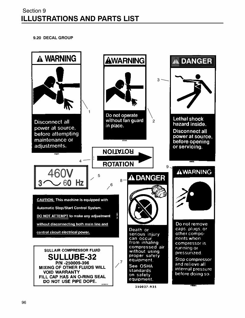
Section 9
ILLUSTRATIONS AND PARTS LIST
96
9.20 DECAL GROUP
DANGER!
1
2
3
4
5
6
7
8
9

Section 9ILLUSTRATIONS AND PARTS LIST
9.20 DECAL GROUP
key partnumber description number quantity
1 sign, warning sever fan 049855 12 sign, warning sever fan port 049965 13 sign, danger electrocution 049850 14 decal, rotation 7” 250021--286 15 decal, voltage international (460V) (I) 02250069--399 16 decal, caution auto start/stop 041065 17 decal, compressor fluid Sullube 32 250023--361 18 sign, danger air breathing 250027--935 19 sign, warning compressor fluid fill 049685 1
(Continued on page 99)
(I) For machine with voltage other than 460V, consult factory for decal part number.
PLEASE NOTE: WHEN ORDERING PARTS, INDICATE SERIAL NUMBER OF COMPRESSOR
97
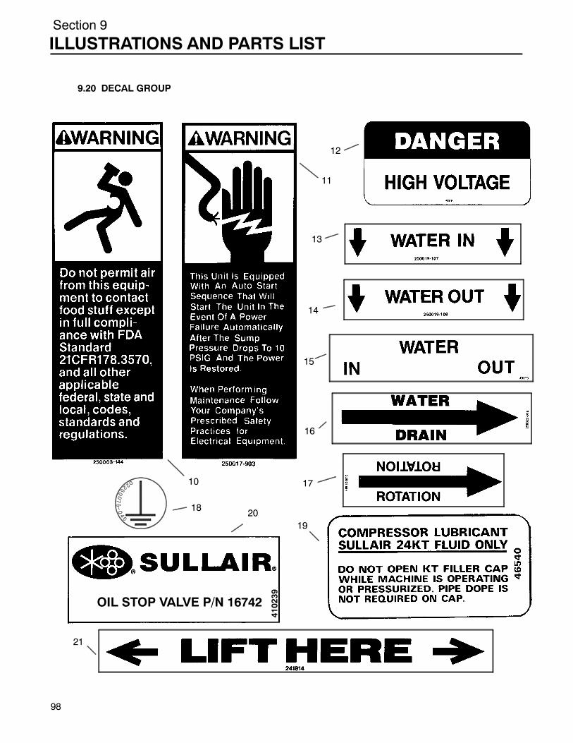
Section 9
ILLUSTRATIONS AND PARTS LIST
9.20 DECAL GROUP
OIL STOP VALVE P/N 16742
410239
11
12
13
14
15
16
17
18
19
10
20
21
98

Section 9ILLUSTRATIONS AND PARTS LIST
9.20 DECAL GROUP (CONTINUED)
key partnumber description number quantity
10 sign, warning food grade 250003--144 111 decal, warning auto start 250017--903 112 decal, danger high voltage 042218 113 decal, water in (I) 250019--107 114 decal, water out (I) 250019--108 115 decal, water in/out (I) 049873 116 decal, water drain 250022--810 117 decal, rotation 3 1/2” 250021--564 118 decal, earth ground 02250075--046 2
Sdecal, protective earth ground (not shown) 02250075--045 1Sdecal, PE designation (not shown) 02250075--540 1
19 decal, compressor lubrication 046540 120 decal, fluid stop valve 410239 121 decal, fork lifting 241814 2
(Continued on page101)
(I) For water--cooled compressors only.
PLEASE NOTE: WHEN ORDERING PARTS, INDICATE SERIAL NUMBER OF COMPRESSOR
99

Section 9
ILLUSTRATIONS AND PARTS LIST
9.20 DECAL GROUP
46415R
22
23
24
26
2728
100
Section 9ILLUSTRATIONS AND PARTS LIST
9.20 DECAL GROUP (CONTINUED)
key partnumber description number quantity
22 decal, ISO 9001 02250057--624 123 decal, 24 KT 046415 224 decal, actuator 250029--836 125 decal, LS Supervisor II front (II) 02250073--284 126 decal, Sullair 02250059--054 127 decal, LS--20 02250061--085 128 decal, SRF 1/4000 fluid 250022--839 1
(Continued on page 103)
(II) See Section 4, Supervisor II Description, Figure 4--1.
PLEASE NOTE: WHEN ORDERING PARTS, INDICATE SERIAL NUMBER OF COMPRESSOR
101
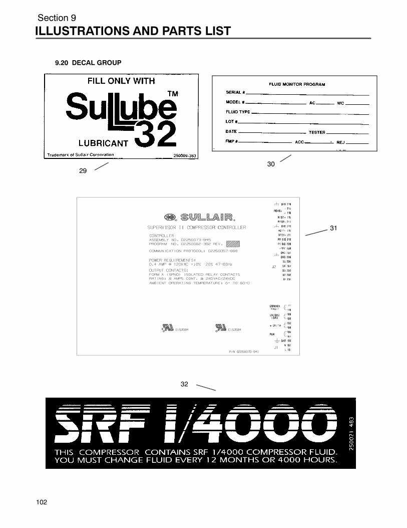
Section 9
ILLUSTRATIONS AND PARTS LIST
1
9.20 DECAL GROUP
2930
32
31
02
Section 9ILLUSTRATIONS AND PARTS LIST
9.20 DECAL GROUP (CONTINUED)
key partnumber description number quantity
29 decal, Sullube 250009--383 130 label, fluid monitor program 250022--725 131 decal, LS std Supervisor II information 02250073--941 132 decal, logo SRF 1/4000 250021--483 133 decal, electrical component (not shown) 250038--457 1
PLEASE NOTE: WHEN ORDERING PARTS, INDICATE SERIAL NUMBER OF COMPRESSOR
103
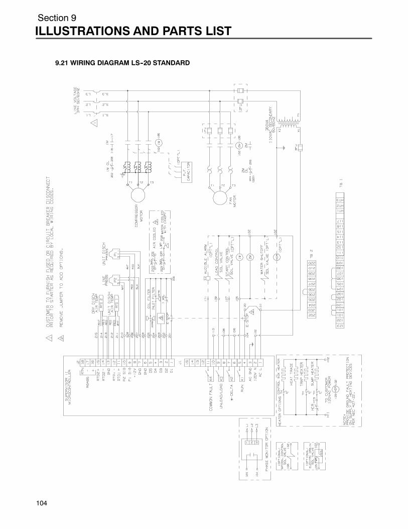
Section 9
ILLUSTRATIONS AND PARTS LIST
10
9.21 WIRING DIAGRAM LS--20 STANDARD
4
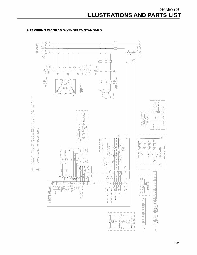
Section 9ILLUSTRATIONS AND PARTS LIST
9.22 WIRING DIAGRAM WYE--DELTA STANDARD
105
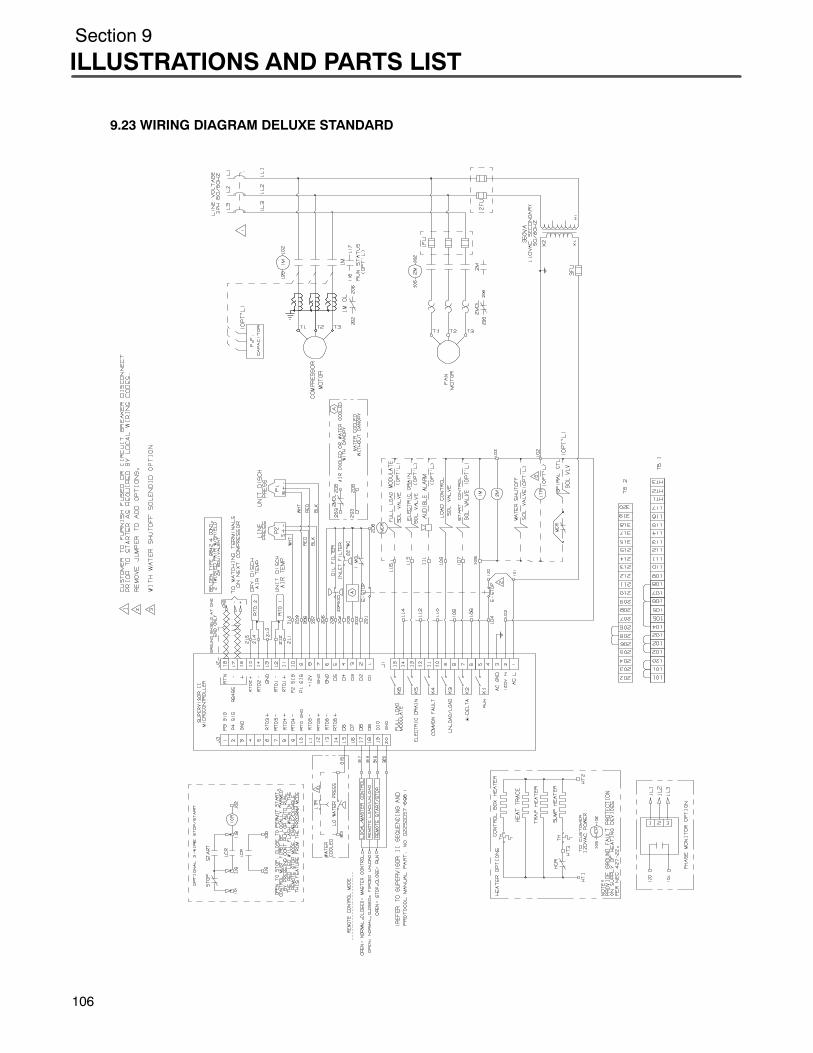
Section 9
ILLUSTRATIONS AND PARTS LIST
106
9.23 WIRING DIAGRAM DELUXE STANDARD
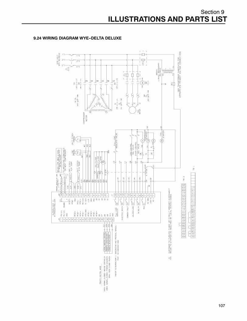
Section 9ILLUSTRATIONS AND PARTS LIST
9.24 WIRING DIAGRAM WYE--DELTA DELUXE
107

Printed in U.S.A.
Specifications Subject ToChange Without Prior Notice
WORLDWIDE SALES AND SERVICE
R
SULLAIR EUROPE, S.A.
SULLAIR CORPORATION3700 East Michigan Boulevard
Michigan City, Indiana 46360 U.S.A.Telephone: 1--219--879--5451
Fax: (219) 874--1273Fax: (219) 874--1835 (Parts)Fax: (219) 874--1288 (Service)
SULLAIR ASIA, LTD.Sullair Road, No. 1Chiwan, Shekou
Shenzhen, Guangdong PRV.PRC POST CODE 518068Telephone: 755--6851686
Fax: 755--6853473
Zone Des Granges BP 8242602 Montbrison Cedex, France
Telephone: 33--477968470Fax: 33--477968499