Embed Size (px)
Citation preview
THESIS FOR THE DEGREE OF DOCTOR OF PHILOSOPHY
Industrial Application of Set-based Concurrent Engineering –
Managing the design space by using Platform System Families
DAG S. RAUDBERGET
Department of Product and Production Development CHALMERS UNIVERSITY OF TECHNOLOGY
Göteborg, Sweden 2015

Industrial Application of Set-‐based Concurrent Engineering – Managing the design space by using Platform System Families DAG S. RAUDBERGET ISBN 978-‐91-‐7597-‐258-‐9 © Dag Raudberget, 2015 Doktorsavhandling vid Chalmers tekniska högskola Ny serie nr. 3939 ISSN 0346-‐XXX718X Published and Distributed by Chalmers University of Technology Department of Product and Production Development Division of Product Development SE – 412 96 Göteborg Sweden
Telephone + 46 (0)31-‐772 1000 Printed in Sweden by Chalmers Reproservice Göteborg, 2015

3
Abstract During product development, most of the customer value, as well as the cost and the quality of a product are defined. This key role of development in industry has led to an intense search for better ways to develop products, software, services and systems. Two development methodologies that have received positive attention for their efficiency are Set-‐Based Concurrent Engineering and platform-‐based design.
This thesis presents the results of implementing the principles of Set-‐Based Concurrent Engineering (SBCE) in platform-‐based design as a means to improve the industrial product development. The contribution is a better understanding of SBCE and new ways to use its principles to support development processes. The results are developed in collaboration with industry and demonstrate that SBCE gives positive effects on many aspects of product development performance and on the resulting products. Further, it clarifies that SBCE has a distinctive way to manage the design space that promotes a thorough understanding of the important design parameters before committing to a specific design.
Finally, this work presents a structured design process for managing the first phases of platform development. The studies in this thesis show that previous approaches in literature do not present methodological support for developing product architectures in the earliest stages of platform development. This work fills this void by introducing a new design methodology for modelling, assessing and narrowing down the architectural design space in the phases before embodiment. It allows exploration of more alternatives in the earliest phases of development, which ultimately may produce better designs.
Keywords: product development, platform-‐based development, set-‐based concurrent engineering, design decisions, functional modelling, configurable components, platform architecture, system family

4

5
Acknowledgements The research work towards this thesis has been carried out in two different Swedish research environments. The first part was conducted at the Department of Mechanical Engineering at the School of Engineering at Jönköping University and the second part leading to this thesis was carried out at the department of Product and Production Development at Chalmers University of Technology in Gothenburg. I would especially like to acknowledge my advisors, Professors Staffan Sunnersjö and Hans Johannesson, for all their support and encouragement during this research. Staffan gave me the opportunity to pursuit doctoral studies in parallel to my teaching job, and Hans brought me to Chalmers when the funding in Jönköping ceased. They both let me find my own way, always providing valuable advice and guidance when I needed it. I would also like to express my appreciation to my hardboiled co-‐authors Christoffer Levandowski and Jonas Landahl for sharing moments of joy and inspiration as well as the hardships of travel. In addition I would also like to mention Marcel Michaelis, Anders Forslund and Daniel Corin Stig whose brilliant discussions of pointless topics makes the coffee breaks something to long for. For the motivating working environment in Jönköping I would like to direct my thanks to Patrik Cannmo, Fredrik Elgh, Joel Johanson and Roland Stolt. I would also like to acknowledge my teaching colleagues Magnus Andersson and Thomas Arnell for posing the difficult questions on how my research could be applied on their cases. This research work would not have been possible without the support and participation of the industrial collaborators who participated in our studies: Thank you Kongsberg Automotive, Scania, SWEREA IVF, Kapsch Traffic Com, Airbus UK and especially Peter Edholm at Geomdev and Ola Isaksson at GKN Aerospace. Funding for the research came from several sources: from the School of Engineering at Jönköping University, the Swedish Governmental Agency for Innovation Systems (VINNOVA), the Wingquist Laboratory VINN Excellence Centre and the European Union Seventh Framework Programme (TOICA – www.toica-‐fp7.eu). This support is greatly appreciated, as is the support from Göran Gustafsson and the research school ProViking. Finally, I would like to thank my family for their support, especially my mother Gull-‐Britt for resolving the difficulties of the English language and my wife Lotta for her endless patience.

6

7
Appended Publications The following research papers form the foundation for this thesis. Paper A: Raudberget, D. (2010). Practical Applications of Set-‐Based Concurrent Engineering in
Industry. Journal of Mechanical Design-‐ Strojniski vestnik. Vol. 56 no. 11, p.685-‐695. Paper B: Raudberget, D. (2010). The Decision Process In Set-‐Based Concurrent Engineering -‐
An Industrial Case Study. Proceedings of the 11th International Design Conference DESIGN 2010, Dubrovnik, Croatia.
Paper C: Raudberget, D. (2011). Enabling Set-‐Based Concurrent Engineering in traditional
product development. Proceedings of the International Conference on Engineering Design, ICED11, Copenhagen, Denmark.
Paper D: Levandowski, C. Raudberget, D. Johannesson, H. (2014). Set-‐Based Concurrent
Engineering for Early Phases in Platform Development. Proceedings of the 21st ISPE International Conference on Concurrent Engineering, CE2014, Beijing, China.
Paper E: Raudberget, D. Michaelis, M. T. Johannesson, H. (2014). Combining Set-‐Based
Concurrent Engineering and Function-‐ Means Modelling to Manage Platform-‐Based Product Family Design. Proceedings of the 2014 IEEE-‐ IEEM, Kuala Lumpur, Malaysia.
Paper F: Raudberget, D. Levandowski, C. Isaksson, O. Kipouros, T. Johannesson, H. Clarkson, J.
(2015). Modelling and assessing platform architectures in Pre-‐embodiment phases through Set-‐Based evaluation and change propagation. Accepted for publication by the International Journal of Aerospace Operations.
For the papers having more than one author, the work on each paper was distributed as follows: Paper E: Dag Raudberget and Christoffer Levandowski elaborated the example and synthesized the theory. They wrote, reviewed and edited the paper in joint collaboration. Hans Johannesson contributed with comments. Paper F: Dag Raudberget and Marcel Michaelis conceived the main idea. Dag Raudberget did the literature analysis, created the case scenario and wrote the paper. Marcel Michaelis and Hans Johannesson contributed with comment and feedback Paper G: Dag Raudberget wrote the paper. All authors contributed in creating the system analysis process and case scenario, as well as providing comments and feedback. Timoleon Kipouros created the Change Propagation calculations.
Additional Publications The following publications are related to the presented research although not making a central contribution to the result. Landahl, J. Raudberget, D. (2015). Assessing system maturity of interacting product and manufacturing alternatives before early technology commitment. Proceedings of the

8
International Association for Management of Technology, IAMOT 2015, Johannesburg, South Africa. Levandowski, C. Corin Stig, D. Raudberget, D. Johannesson, H. (2015). Accommodating emerging technologies in existing product platforms. Proceedings of the International Association for Management of Technology, IAMOT 2015, Johannesburg, South Africa. Raudberget, D. Bjursell, C. (2014). A3 reports for knowledge codification, transfer and creation in research and development organisations. International Journal of Product Development, vol. 19, nr 5/6, p. 413-‐431. Raudberget, D. Edholm, P. Andersson, M. (2012). Implementing the principles of Set-‐based Concurrent Engineering in Configurable Component Platforms. Proceedings of NordDesign 2012, Aalborg, Denmark. Raudberget, D. Sunnersjö, S. (2010). Experiences of Set-‐ based Concurrent Engineering in four product developing companies. Proceedings of the TMCE 2010, April 12–16, 2010.

9
List of abbreviations 3D.........Three-‐dimensional C............Constraint CAD.....Computer Aided Design CAE......Computer Aided Engineering CC.........Configurable Component CCM.....Configurable Component Modeler CE.........Concurrent Engineering CI..........Control Interface CS..........Composition Set DRM.....Design Research Methodology DS.........Design Solution DSM.....Design Structure Matrix e.g..........exempli gratia (for the sake of example) et al.......et alii (and others) etc..........et cetera (and more) F-‐M.......Function-‐Means FR..........Functional Requirement IA..........Interaction icb.........is constrained by i.e...........id est (that is) IF...........Interface iib..........is influenced by ipmb.....is partly met by isb..........is solved by IT..........Information Technology iw..........interacts with LPD.......Lean Product Development LPT.......Low Pressure Turbine NASA...National Space and Aeronautics Administration p............page PDM.....Product Data Management pp..........pages rf............requires function RQ.........Research Question SAR.......Spiral of Applied Research SBCE....Set-‐Based Concurrent Engineering TEC......Turbine Exhaust Case TRS......Turbine Rear Structure VDD…..Value Driven Design

10

11
Contents
ABSTRACT ........................................................................................................................................................ 3 ACKNOWLEDGEMENTS ................................................................................................................................ 5 APPENDED PUBLICATIONS ........................................................................................................................ 7 ADDITIONAL PUBLICATIONS ..................................................................................................................... 7 LIST OF ABBREVIATIONS ............................................................................................................................ 9 1 INTRODUCTION ..................................................................................................................................... 13 1.1 SET-‐BASED CONCURRENT ENGINEERING AND THE SIMILARITIES TO PLATFORM DEVELOPMENT ........ 13 1.2 MOTIVATION FOR THE RESEARCH ..................................................................................................................... 15 1.2.1 Scope of the research .................................................................................................................................. 15 1.2.2 Industrial Goals ............................................................................................................................................. 16 1.2.3 Scientific Goals ............................................................................................................................................... 16
1.3 RESEARCH QUESTIONS: ....................................................................................................................................... 16 1.4 DELINEATION OF THE RESEARCH ...................................................................................................................... 17 1.5 DISPOSITION OF THE THESIS .............................................................................................................................. 17
2 FRAME OF REFERENCE ....................................................................................................................... 19 2.1 DESIGN METHODOLOGY ...................................................................................................................................... 19 2.1.1 The generic engineering design process ............................................................................................. 19 2.1.2 Integrated Product Development and Concurrent Engineering ............................................. 20
2.2 SET-‐BASED CONCURRENT ENGINEERING ........................................................................................... 21 2.2.1 The three principles ..................................................................................................................................... 22 2.2.2 Integration events ........................................................................................................................................ 24 2.2.3 Trade-‐offs and trade-‐off curves .............................................................................................................. 25 2.2.4 The specification management process of Set-‐ based Concurrent Engineering ............... 26 2.2.5 Industrial applications of Set-‐ based Concurrent Engineering ................................................ 26
2.3 POPULAR DECISION METHODS IN DESIGN ........................................................................................................ 27 2.3.1 The decision process of Set-‐ Based Concurrent Engineering ..................................................... 27 2.3.2 Pugh and Kesselring’s matrix selection methods for comparing different solutions. .... 28 2.3.3 Design decisions based on axioms ......................................................................................................... 29
2.4 THE ROLE OF KNOWLEDGE MANAGEMENT ...................................................................................................... 29 2.4.1 The emphasis on design knowledge in Set-‐based Concurrent Engineering. ....................... 30
2.5 FUNCTIONAL MODELLING OF PRODUCTS AND SYSTEMS ................................................................................ 31 2.5.1 Enhanced Function-‐Means modelling ................................................................................................. 31 2.5.2 Manufacturing oriented and development oriented platforms ............................................... 32 2.5.3 Theory of Domains ....................................................................................................................................... 33
2.6 CONFIGURABLE COMPONENT PLATFORM MODELLING .................................................................................. 35 2.7 THE BANDWIDTH OF PRODUCT PLATFORMS ................................................................................................... 36 2.8 SET-‐BASED CONCURRENT ENGINEERING FOR PLATFORM DEVELOPMENT ................................................ 37 2.9 MODELLING AND EVALUATING FUNCTIONAL PRODUCT PLATFORM CONCEPTS ........................................ 38 2.10 CHANGE PROPAGATION METHOD ................................................................................................................... 39 2.11 CONCLUDING SUMMARY ................................................................................................................................... 39 2.11.1 Opportunities for research ..................................................................................................................... 40
3 RESEARCH APPROACH ........................................................................................................................ 41 3.1 DESIGN RESEARCH ................................................................................................................................................ 41 3.1.1 Classification of design research ............................................................................................................ 41 3.1.2 Available research frameworks ............................................................................................................. 43
3.2 APPLIED RESEARCH APPROACH ......................................................................................................................... 45 3.2.1 Research sequence in relation to Design Research Methodology ........................................... 45
3.3 COLLECTION OF EMPIRICAL MATERIAL ............................................................................................................ 46 3.4 VALIDATING AND VERIFYING THE QUALITY OF THE RESULTS ...................................................................... 47
12
3.4.1 Criteria for valid design research according to Cross .................................................................. 48 3.4.2 Criteria for valid design research according to Buur ................................................................... 48
4 RESULTS .................................................................................................................................................. 49 4.1 PAPER A: EXPLORING SET-‐BASED CONCURRENT ENGINEERING. ............................................................... 49 4.1.1 What are the effects of SBCE? ................................................................................................................. 49
4.2 PAPER B: CLARIFYING THE SET-‐BASED NARROWING PROCESS ................................................................... 52 4.2.1 Traditional decision process .................................................................................................................... 53 4.2.2 Set-‐based decision process ....................................................................................................................... 54
4.3 PAPER C: A PROCESS AND TOOL TO INTRODUCE SET-‐BASED CONCURRENT ENGINEERING .................. 56 4.3.1 A novel design process ................................................................................................................................ 57 4.3.2 A supporting computer tool ..................................................................................................................... 58
4.4 PAPER D: SET-‐BASED CONCURRENT ENGINEERING FOR PLATFORM CONCEPT DEVELOPMENT ........... 62 4.4.1 Functional modelling of interactions .................................................................................................. 63
PAPER E: NARROWING DOWN PRODUCT PLATFORMS USING SET-‐BASED PRINCIPLES AND FUNCTION-‐ MEANS MODELLING ........................................................................................................................................................................ 66 4.4.2 Illustrative example ..................................................................................................................................... 66 4.4.3 Creating product platform architectural options .......................................................................... 67
4.5 PAPER F: MODELLING AND ASSESSING PLATFORM ARCHITECTURES IN EARLY PHASES THROUGH SET-‐BASED EVALUATION AND CHANGE PROPAGATION. ..................................................................................................... 70 4.5.1 Illustrative example ..................................................................................................................................... 71 4.5.2 Generate and structure functional models ........................................................................................ 73 4.5.3 Specify and generate architectures ...................................................................................................... 73 4.5.4 Narrow down architectures ..................................................................................................................... 75
5 DISCUSSION ............................................................................................................................................ 77 5.1 ANSWERING THE RESEARCH QUESTIONS ......................................................................................................... 77 5.2 RESEARCH EVALUATION ............................................................................................................................. 80 5.2.1 Evaluating the research according to Buur ...................................................................................... 80 5.2.2 Evaluating the research according to Cross ..................................................................................... 81
6 CONCLUSIONS AND FUTURE WORK ............................................................................................... 83 6.1 CONCLUSIONS: ...................................................................................................................................................... 83 6.2 FUTURE WORK ..................................................................................................................................................... 84
7 REFERENCES ........................................................................................................................................... 85
13
1 Introduction During product development most of the customer value as well as the cost and the quality of a product are defined. A first-‐class development organisation is therefore crucial in maintaining a profitable market position.
One may argue that the final product properties are created by the manufacturing system, and that manufacturing thereby determines the cost and the quality of a product. Studies show, however, that the best performing manufacturing companies could credit part of their success to their attention to design (Womack & Jones, 1990). Other authors stress that the design process is the most important factor affecting the outcome of the production system (M. Kennedy, Harmon, & Minnock, 2008; Morgan & Liker, 2006; Whitney, 1993). This key role of development in industry has led to an intense search for better ways to develop products, software, services and systems.
One design methodology that has received positive attention for its efficiency is Set-‐Based Concurrent Engineering (Bernstein, 1998; M. Kennedy et al., 2008; Morgan, 2002; Morgan & Liker, 2006; D. K. Sobek, A. Ward, & J. Liker, 1999; D. Sobek, K., 1997; A. C. Ward, Liker, Sobek, & Cristiano, 1994; A. Ward, Liker, Cristiano, & Sobek, 1995; Allen C. Ward & Sobek, 2014). Some authors optimistically claim that Set-‐Based Concurrent Engineering (SBCE) and related practices from Lean Development are four times more productive than traditional development models (Morgan & Liker, 2006; Allen C. Ward & Sobek, 2014). Another path to efficient development is the product platform strategy. There are several types of platforms (Zhang, 2015) characterised by the type of platform elements that are used to create it. The common denominator is that platforms enable a systematic reuse of corporate assets. Platform literature commonly describe manufacturing oriented platforms having components that are reusable in a several products (Jiao, Simpson, & Siddique, 2007). Here, the combination of different components enables a variety of products, while keeping the number of individual components low, thus creating economics of scale in manufacturing. For some sectors of manufacturing industry, a platform based on the reuse of components may not be economic. Typical examples are firms with an engineer-‐to-‐order business model or firms having low production volumes as in the aerospace industry. These need instead to focus on the economics of scale in product development, which is not met by the reuse of components. Combining SBCE and platform-‐based design would provide a highly effective arrangement. However, in the platform design process several product variants are created simultaneously to satisfy a wide set of customer requirements (R. Pedersen, 2009). This makes platform development more difficult than designing single products. SBCE is also challenging to apply and is described by M. Kennedy et al. (2008) as difficult to implement. Combining the development of several product variants of a platform with the characteristic broad search for solutions of SBCE will result in a huge design space that is difficult to manage and there are a limited number of studies that take on the challenge to use SBCE to develop a product family instead of a single design. This thesis focuses on improving development processes and therefore considers development platforms as opposed to manufacturing oriented platform types based on previously designed components as reusable assets.
1.1 Set-‐based Concurrent Engineering and the similarities to platform development
In short, the concept of SBCE is characterized by developing multiple solutions to design problems in parallel. It considers sets of design alternatives rather than a specific design. As the design evolves, the sets of solutions are gradually narrowed down based on relevant information from customers, manufacturing departments, tests, and other sources. In the end, only one solution is left.
14
A “set” is a part of the design space representing a palette of different possibilities for the emerging system. It holds multiple versions of elements having a common denominator such as a family of design solutions for a specific requirement, variations on an industrial design, possible manufacturing options, etc.
The term “Set-‐Based” is opposed to the term “Point-‐based” (A. Ward et al., 1995), describing the traditional development methodology. The separation of development into two distinct categories is a way to pinpoint their differences and a typical design processes can have both Set-‐based and Point-‐based elements. In this context, a Point-‐based design is characterized by an early selection and approval of one “best” specific design, a single point in the solution space. This initial design is then refined, re-‐worked and sequentially modified until an acceptable solution is found.
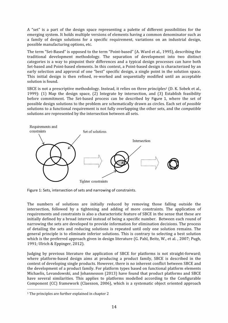
SBCE is not a prescriptive methodology. Instead, it relies on three principles1 (D. K. Sobek et al., 1999): (1) Map the design space, (2) Integrate by intersection, and (3) Establish feasibility before commitment. The Set-‐based process can be described by Figure 1, where the set of possible design solutions to the problem are schematically drawn as circles. Each set of possible solutions to a functional requirement is not fully overlapping the other sets, and the compatible solutions are represented by the intersection between all sets.
Figure 1: Sets, intersection of sets and narrowing of constraints.
The numbers of solutions are initially reduced by removing those falling outside the intersection, followed by a tightening and adding of more constraints. The application of requirements and constraints is also a characteristic feature of SBCE in the sense that these are initially defined by a broad interval instead of being a specific number. Between each round of narrowing the sets are developed to provide information for elimination decisions. The process of detailing the sets and reducing solutions is repeated until only one solution remains. The general principle is to eliminate inferior solutions. This is contrary to selecting a best solution which is the preferred approach given in design literature (G. Pahl, Beitz, W., et al. , 2007; Pugh, 1991; Ulrich & Eppinger, 2012). Judging by previous literature the application of SBCE for platforms is not straight-‐forward; where platform-‐based design aims at producing a product family, SBCE is described in the context of developing single products. However, there is no inherent conflict between SBCE and the development of a product family. For platform types based on functional platform elements Michaelis, Levandowski, and Johannesson (2013) have found that product platforms and SBCE have several similarities. This applies to platforms modelled according to the Configurable Component (CC) framework (Claesson, 2006), which is a systematic object oriented approach 1 The principles are further explained in chapter 2
15
that supports the modelling and development of product platforms based on Functions-‐Means methodology (Svendsen & Hansen, 1993). Michaelis et al. (2013) and Levandowski, Michaelis, and Johannesson (2014) present ways to model development platforms in different life cycles. The work focuses on the preparation of platforms and corresponding manufacturing system and outline a process where the modelling of functions and means corresponds to the SBCE principle Map the design space. Each functional requirement is solved by a set of several alternative design solutions, rather than selecting and pursuing one solution. The principle Integrate by intersection is managed by identifying interactions between design solutions, where the functional relations in the CC-‐model and trade-‐off curves are used to describe the intersection of interacting sets. This is used to eliminate unfeasible alternatives. For the last SBCE principle, Establish feasibility before commitment, the authors suggest to model configurable components by partitioning the F-‐M tree into discrete CC-‐objects that can be separately tested and validated within their working range. To further apply the support offered by the principles of SBCE also for platforms, multiple platform concepts must be considered and evaluated efficiently. In this work the applied mindset is that a Set-‐based approach essentially implies that the principles of SBCE are followed. Regardless of which platform type is considered, conceiving a product platform requires a massive workload compared to development of single products. To design multiple alternative platforms to a high level of detail is therefore not feasible from a resource and lead-‐time perspective and methods to evaluate platform concepts in different phases of development are therefore needed.
1.2 Motivation for the research
In this thesis, the research is driven by the consideration of both a scientific challenge and an industrial opportunity. The overall purpose of the research is to investigate if the productivity of the design process can be improved if it is supported by the combined use of Set-‐based Concurrent Engineering principles and platform-‐based modelling approaches. Here, there are three primary knowledge gaps that motivate the research: The first gap is lack of knowledge about the impact and relevance of the principles of SBCE for problems and industrial settings outside the original study.
The second gap is the question of how SBCE is used to identify promising regions of the design space and converge to a solution. The design space in platform development is larger than in traditional development and SBCE uses a distinctive approach to manage this. Even though this approach is well known (A. Ward et al., 1995) there are no previous studies that explain how to apply it in practice, especially not for platforms.
The last gap is the lack of methodology supporting early phases of product and platform development with SBCE and EF-‐M modelling. This addresses the challenges of creating and evaluating system layouts or platform architectures, which is one of the most important tasks in development.
1.2.1 Scope of the research
The scope of the research is to study SBCE and platform based design both in theory and through industrial cases to gain a better understanding of the subject. The approach is to apply the principles of SBCE to different development processes. It includes studies of the introduction of SBCE pilot projects, analysis of the results and identification of important key features. Existing descriptions and theories concerning SBCE and product platforms are used as an initial starting point to develop design support based on the three principles of SBCE.
The decision process of SBCE is also included in the scope since the methods for evaluations of designs are different compared to traditional Point-‐based development processes. Design
16
decisions have a fundamental influence on all aspects of product and platform development, and it is therefore important to study the details of a Set-‐based decision process.
Finally, processes and tools to introduce SBCE are developed. These should support product and platform design with the three principles of Set-‐based Concurrent Engineering and be consistent with findings in this research and with previously reported results.
1.2.2 Industrial Goals
The previously stated high efficiency of SBCE and platform–based design makes the concepts relevant for product developing industry. An evaluation of the principles of SBCE in an industrial setting outside the original study (A. Ward et al., 1995) is therefore important but has not been documented before. Even though there are prior examples of SBCE trials, the principles have not all been consistently applied or evaluated in industry.
In order to introduce SBCE, there are practical difficulties that need to be overcome: SBCE is usually considered incompatible to traditional phased project models (M. Kennedy et al., 2008; Morgan & Liker, 2006; Allen C. Ward & Sobek, 2014), which are a common way to organize an industrial development process. Another drawback is that SBCE is characterised by a slow decision process (A. Ward et al., 1995), an effect that is usually considered to have a negative effect on the development performance. The industrial goal of this work is therefore to improve the support for development of technical system design by implementing the principles of SBCE.
Examples of the application of SBCE to platforms are previously described in literature and this thesis contributes by developing methods for the early phases of design. From an industrial point of view, the principles do not give any advice for how to implement them. A structured way to introduce the three principles of Set-‐based Concurrent Engineering is therefore needed, for platforms as well as for single products.
1.2.3 Scientific Goals
From a scientific standpoint, there are also questions that motivate the research. The principles of SBCE were mainly formulated on the grounds of one industrial example [1-‐3] and from theoretical simulations of a design compiler (A. C. Ward, 1989). There are no prior studies showing that the three principles, extracted out of one firm’s development process, would improve the efficiency or effectiveness of another firm’s design process.
Another goal is to use the principles of SBCE to support platform concept design. Michaelis et al. (2013) and Levandowski et al. (2014) present ways to model platforms in a Set-‐based way. They focus on the preparation of platforms and corresponding manufacturing system using the approach taken for the Configurable Component framework (Claesson, 2006). They do not cover the earliest phases of development and this thesis aims at elaborating design support for the conceptual phases of platform design using Set-‐based principles. The support must also present new ways to assess platform architectures that ensure the feasibility of the platform concept before commitment to a specific design.
1.3 Research questions: The following research questions were formulated to drive the research: RQ 1: How do the principles of SBCE affect industrial product development and its
performance in different environments?

17
The first Research Question has several dimensions and includes how SBCE can be introduced to support industrial product and platform development and how it affects the development process and the resulting products. RQ2: How can the principles of SBCE be applied to identify feasible regions of the design
space and support convergence to feasible solutions? The way that SBCE can narrow down the design space is one of the most characteristic ways that SBCE distinguishes itself from point-‐based development. It includes both clarifying how decisions are made and how requirements are handled. Consequently, this research question is touched upon in all papers. RQ3: How can methods and tools derived from SBCE and EF-‐M modelling be used to
find feasible system architectures and function realizing features in early phases of product and platform development?
One of the most critical steps when developing new products and systems is in the establishment of a system layout or a platform architecture. Existing design methodologies do not provide sufficient support for this purpose. The aimed answer to RQ3 is expected to contribute to closing this methodological gap.
1.4 Delineation of the Research This thesis does not pursue the objective of describing how to create the sets used in SBCE even though the initial design space is an important prerequisite of SBCE. Generating this is a creative process and there are several methods, tools and processes in literature that describe different aspects of generating ideas and organising development to enhance creativity. For the same reason, the research does not address the practical task of creating F-‐M trees. Creating F-‐M structures by either breaking down existing systems or building up new systems requires creativity and contextual technical skills, which is out of scope for this research. There are several other areas that are not covered by this research. Mathematical modelling of phenomena related to SBCE and platforms are rather mature areas and are therefore not considered here. Nor is the concept of manufacturing oriented platform types based on components since this thesis focuses on development platforms, specifically the object oriented Configurable Component approach. Also for this reason, modularisation is not studied, even though Allen C. Ward and Sobek (2014) p. 271 state that there is a strong link between modularisation and Set-‐based thinking. Modularisation is a research field in its own right that is closely connected to component based platform development.
1.5 Disposition of the thesis
This thesis consists of an introductory part, covering the background, the goals and research questions. It further presents the relevant underlying theories and the applied research approach, leading up to the summary of the six contributing publications. Lastly, it discusses the quality of the results and presents the conclusions and suggests future work.
Chapter 1 hold the introduction including background and aim of the research.

18
Chapter 2 describes the frame of reference and related work.
Chapter 3 presents the research approach.
Chapter 4 presents the findings of the appended papers.
Chapter 5 discusses the implications, the reliability, and the validity of the results.
Chapter 6 presents conclusions and an outlook on future work.
19
2 Frame of Reference This chapter presents a selection of literature aiming at positioning Set-‐based Concurrent Engineering in relation to platform development and existing design methodologies. Some methodologies are fundamental for the research while others provide a contextual overview. In this thesis, SBCE is presented in the context of functional platform development.
2.1 Design Methodology Companies often use a formal design methodology to create products, services and systems. By using a formal design methodology, the development activities are transformed from art and craftsmanship to a structured, repeatable process. From an industrial point of view, the two main purposes of using methods and processes are to improve the cost and speed of the engineering process, and/or to improve the cost, and quality of the outcome of the engineering process. A methodology is defined by Vladimir Hubka and Eder (1996) as a “coordinated grouping of methods”. It is in its nature prescriptive, where certain procedural models should be followed, in order to receive the stated benefits of the methodology. There are numerous design methodologies, all targeting different areas of design and in the following section the design methods relevant to Set-‐based Concurrent Engineering and product platforms are discussed.
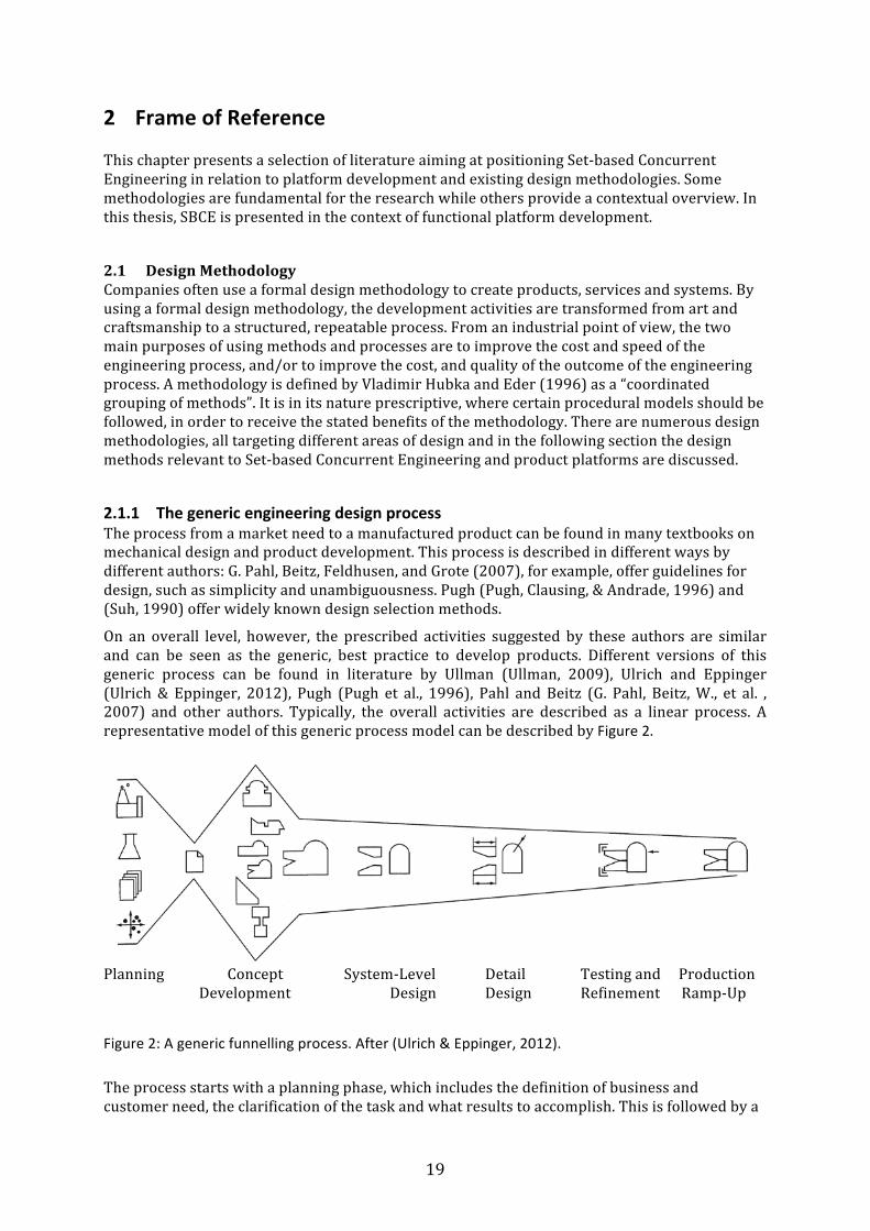
2.1.1 The generic engineering design process The process from a market need to a manufactured product can be found in many textbooks on mechanical design and product development. This process is described in different ways by different authors: G. Pahl, Beitz, Feldhusen, and Grote (2007), for example, offer guidelines for design, such as simplicity and unambiguousness. Pugh (Pugh, Clausing, & Andrade, 1996) and (Suh, 1990) offer widely known design selection methods.
On an overall level, however, the prescribed activities suggested by these authors are similar and can be seen as the generic, best practice to develop products. Different versions of this generic process can be found in literature by Ullman (Ullman, 2009), Ulrich and Eppinger (Ulrich & Eppinger, 2012), Pugh (Pugh et al., 1996), Pahl and Beitz (G. Pahl, Beitz, W., et al. , 2007) and other authors. Typically, the overall activities are described as a linear process. A representative model of this generic process model can be described by Figure 2.
Planning Concept System-‐Level Detail Testing and Production Development Design Design Refinement Ramp-‐Up
Figure 2: A generic funnelling process. After (Ulrich & Eppinger, 2012).
The process starts with a planning phase, which includes the definition of business and customer need, the clarification of the task and what results to accomplish. This is followed by a

20
concept development, a wide search for possible solutions. As the work progresses, it passes through steps intending to ensure a high quality product: system level design, detail design, testing and refinement and production ramp up, etc. One important feature of the process is the methods deployed to reduce the number of alternative design solutions, where the objective is to select the most promising alternative to spend resources on. On an overall level, the Set-‐based process seems rather similar to this generic process. In Figure 2 however, the design iterations and loopbacks are not described, i.e. when the process has to return to an earlier stage of development. Theses iterations can cause costly rework (B. M. Kennedy, Sobek, & Kennedy, 2014). A Set-‐based approach can be characterised as convergent rather than iterative. There is no distinct phase where the best alternative must be chosen or specifications be fixed.
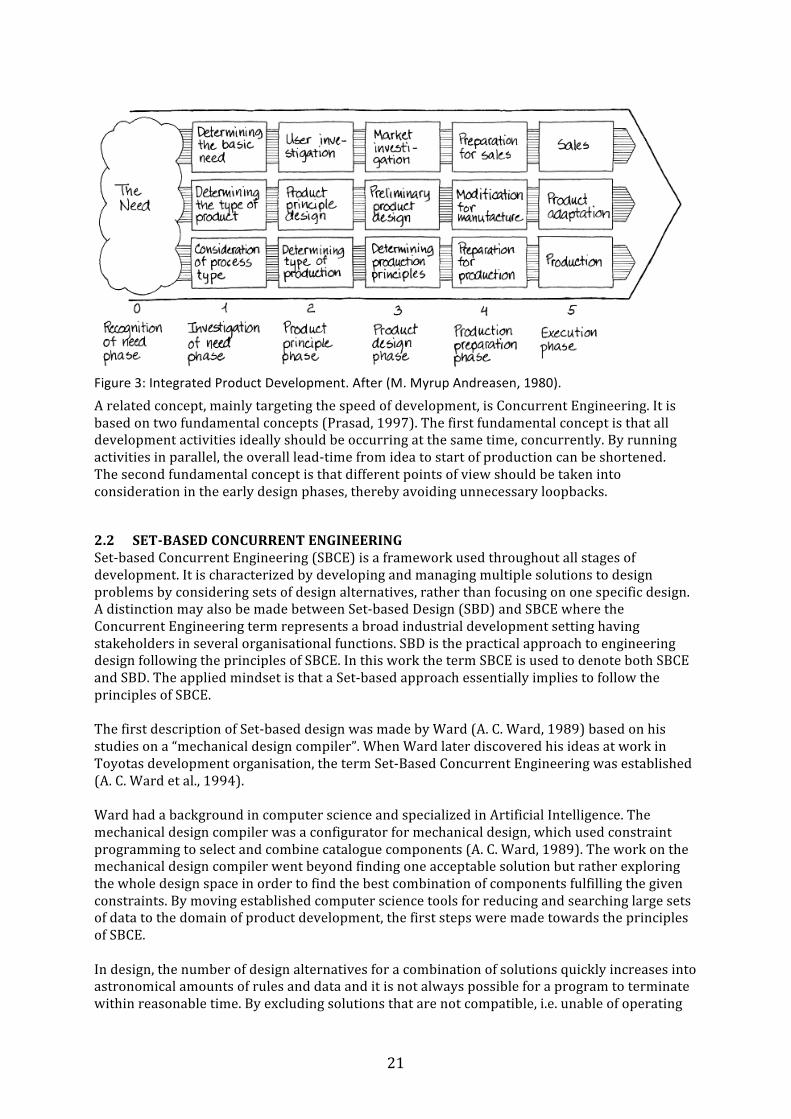
2.1.2 Integrated Product Development and Concurrent Engineering To discuss Set-‐based Concurrent Engineering, knowledge of the related concepts Integrated Product Development (M. M. Andreasen & Hein, 1997) and (point-‐based) Concurrent Engineering (Prasad, 1997) is needed. These are processes that emphasize the interdisciplinary nature of development and are created to overcome different drawbacks of a serial development process. The serial process can be seen as a "relay race" where one set of activities is completed before the information is passed on to the technical discipline that is responsible for the next set of activities. It can be characterised by a series of sequential tasks with little or no communication between functional disciplines. One important drawback of a serial process is the prolonged development lead-‐ times caused by the inability to process information in parallel. Another drawback is the possibility of iterative design loopbacks since feedback from other technical disciplines comes late. This increases both development costs and development lead-‐ times since errors discovered later are more costly and time-‐consuming to correct compared to errors discovered early in the design process. To overcome the difficulties caused by poor communication between functional departments, Integrated Product Development was created (M. M. Andreasen & Hein, 1997). Here, development is performed in cross-‐functional teams enabling quick and un-‐bureaucratic communication. In Figure 3 this can be seen as parallel activities instead of sequential activities: the analysis of the market and customer need run in parallel with product and process design, aiming at good compromises between the various requirements and constraints.
21
Figure 3: Integrated Product Development. After (M. Myrup Andreasen, 1980).
A related concept, mainly targeting the speed of development, is Concurrent Engineering. It is based on two fundamental concepts (Prasad, 1997). The first fundamental concept is that all development activities ideally should be occurring at the same time, concurrently. By running activities in parallel, the overall lead-‐time from idea to start of production can be shortened. The second fundamental concept is that different points of view should be taken into consideration in the early design phases, thereby avoiding unnecessary loopbacks.
2.2 SET-‐BASED CONCURRENT ENGINEERING Set-‐based Concurrent Engineering (SBCE) is a framework used throughout all stages of development. It is characterized by developing and managing multiple solutions to design problems by considering sets of design alternatives, rather than focusing on one specific design. A distinction may also be made between Set-‐based Design (SBD) and SBCE where the Concurrent Engineering term represents a broad industrial development setting having stakeholders in several organisational functions. SBD is the practical approach to engineering design following the principles of SBCE. In this work the term SBCE is used to denote both SBCE and SBD. The applied mindset is that a Set-‐based approach essentially implies to follow the principles of SBCE. The first description of Set-‐based design was made by Ward (A. C. Ward, 1989) based on his studies on a “mechanical design compiler”. When Ward later discovered his ideas at work in Toyotas development organisation, the term Set-‐Based Concurrent Engineering was established (A. C. Ward et al., 1994). Ward had a background in computer science and specialized in Artificial Intelligence. The mechanical design compiler was a configurator for mechanical design, which used constraint programming to select and combine catalogue components (A. C. Ward, 1989). The work on the mechanical design compiler went beyond finding one acceptable solution but rather exploring the whole design space in order to find the best combination of components fulfilling the given constraints. By moving established computer science tools for reducing and searching large sets of data to the domain of product development, the first steps were made towards the principles of SBCE. In design, the number of design alternatives for a combination of solutions quickly increases into astronomical amounts of rules and data and it is not always possible for a program to terminate within reasonable time. By excluding solutions that are not compatible, i.e. unable of operating
22
in combination with elements in the other sets, the design space can be pruned. This saves execution time, without sacrificing any potentially good solutions. Applying a constraint of the type “220V < Voltage < 240V” to a set of electric components, terminates the configurations using 110V or 400V components. More complex constraints can be propagated according to rules and laws of physics. The start of the research on SBCE was when Ward discovered that this process also was used as the backbone of a previously unknown design methodology at Toyota Motor Corporation (A. Ward et al., 1995). The process was, however, not executed in software but by engineers applying design constraints to sets of design solutions in a converging design process.
2.2.1 The three principles SBCE is not a prescriptive methodology; instead it relies on three principles (D. K. Sobek, A. C. Ward, & J. K. Liker, 1999). This implies that SBCE needs to be adapted to each individual application. The principles are given below: 1. Map the design space: -‐ Define feasible regions.
-‐ Explore trade-‐offs by designing multiple alternatives. -‐ Communicate sets of possibilities.
2. Integrate by intersection: -‐ Look for intersections of feasible sets. -‐ Impose minimum constraint. -‐ Seek conceptual robustness.
3. Establish feasibility -‐ Narrow sets gradually while increasing detail. before commitment: -‐ Stay within sets once committed.
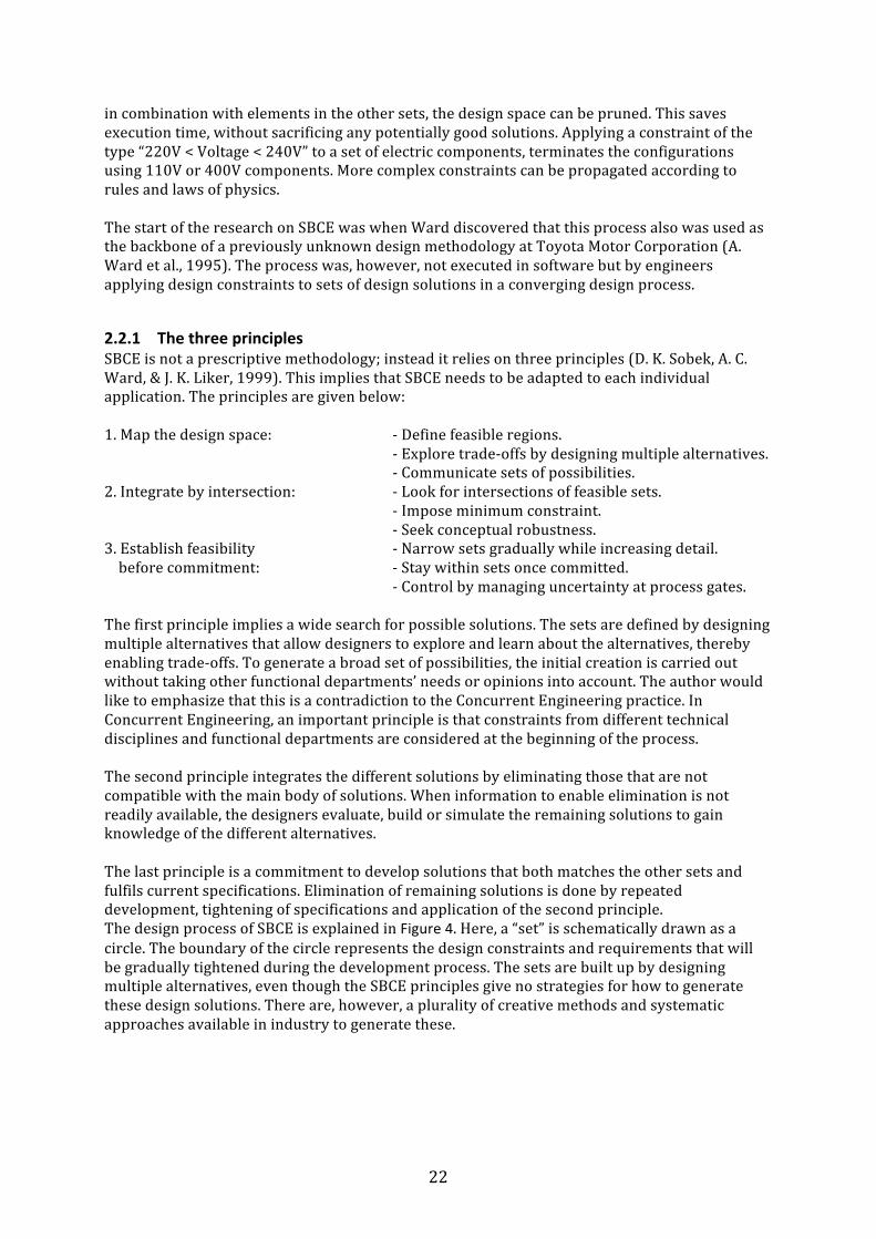
-‐ Control by managing uncertainty at process gates. The first principle implies a wide search for possible solutions. The sets are defined by designing multiple alternatives that allow designers to explore and learn about the alternatives, thereby enabling trade-‐offs. To generate a broad set of possibilities, the initial creation is carried out without taking other functional departments’ needs or opinions into account. The author would like to emphasize that this is a contradiction to the Concurrent Engineering practice. In Concurrent Engineering, an important principle is that constraints from different technical disciplines and functional departments are considered at the beginning of the process. The second principle integrates the different solutions by eliminating those that are not compatible with the main body of solutions. When information to enable elimination is not readily available, the designers evaluate, build or simulate the remaining solutions to gain knowledge of the different alternatives. The last principle is a commitment to develop solutions that both matches the other sets and fulfils current specifications. Elimination of remaining solutions is done by repeated development, tightening of specifications and application of the second principle. The design process of SBCE is explained in Figure 4. Here, a “set” is schematically drawn as a circle. The boundary of the circle represents the design constraints and requirements that will be gradually tightened during the development process. The sets are built up by designing multiple alternatives, even though the SBCE principles give no strategies for how to generate these design solutions. There are, however, a plurality of creative methods and systematic approaches available in industry to generate these.
23
Figure 4: The Set-‐based process. Adapted and redrawn from (Bernstein, 1998).
To reduce the number of solutions two different approaches are used. One approach is to identify designs violating the constraints and requirements. This is a common approach in design methodology. However, the management of requirements is an important distinction from traditional development (Morgan & Liker, 2006). In SBCE the requirement specifications are initially defined by a broad interval instead of being a specific number. This adds flexibility to the engineering design specifications that can be used to trade off alternatives. The second approach is to find the intersection where members of the individual sets are compatible (A. Ward et al., 1995) i.e. where the solutions are capable of interacting and operating with each other. This is a different approach than the traditional point-‐based selection. Instead of using different methods for ranking and selecting one or a few concepts for further development, the SBCE decision process is based on a rejection of the least suitable solutions. Rather than making an educated guess of the performance of a future design, SBCE carries forward all implementations that cannot yet be eliminated. This is a robust process since the consequences of an incorrect choice are fairly small. Rejecting the third worst solution instead of the worst is less critical compared to the magnitude of failure if the third best alternative is picked for development instead of the best. The design process converges by repeatedly tightening the specifications and actively searching for intersections/incompatibilities. This is represented in Figure 4 by narrowing the boundaries of the circles. Before narrowing, new information is needed. Information can be obtained in several ways such as the elaboration of remaining alternatives, by testing, improved customer knowledge or information from manufacturing. Specifications and requirements are gradually narrowed down to a fixed point, but are flexible during the process, allowing engineers to compromise on different aspects. The set of possible solutions decreases step by step, but is balanced by the desire to keep the design space unrestricted until sufficient information is acquired to enable design commitments. In the end, only one solution remains. Although it seems circumstantial, studies have shown that the SBCE decision process is effective (A. Ward et al., 1995) . One reason for this may be that choosing alternatives requires detailed knowledge of all different alternatives while the elimination of alternatives requires only partial
24
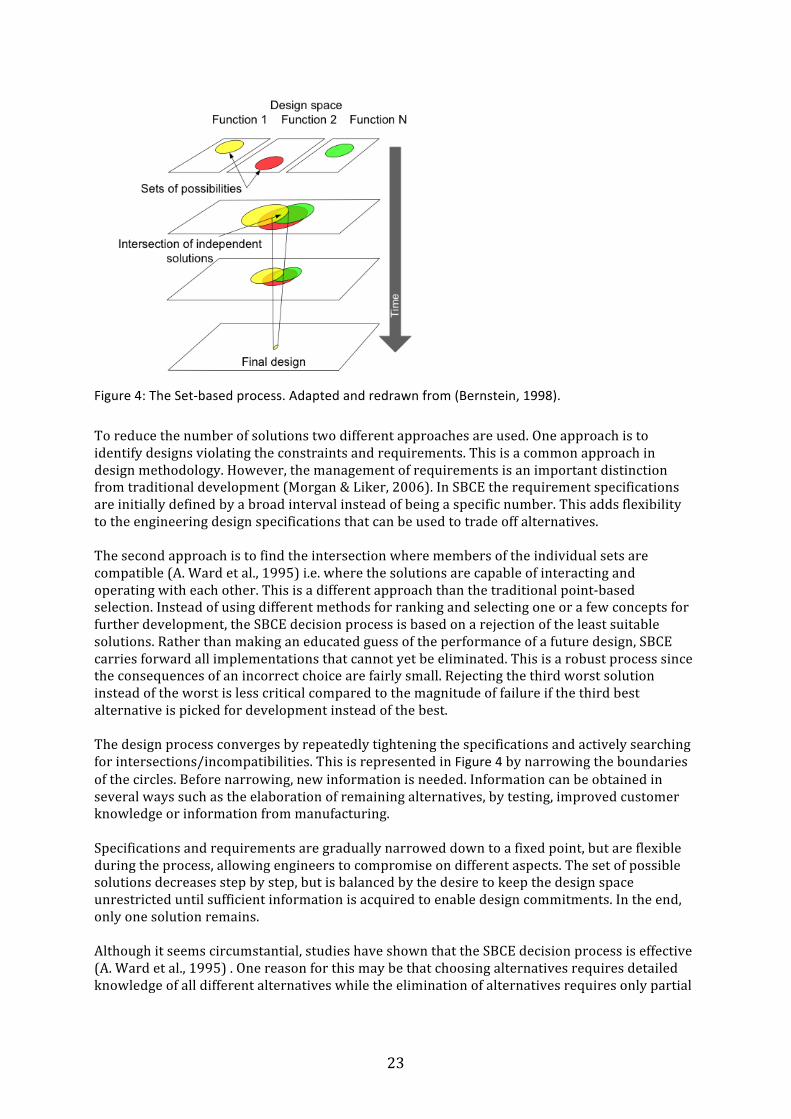
information. The opposite of Set-‐based is the widely used traditional “Point-‐based” (A. Ward et al., 1995) development methodology shown in Figure 5.
Figure 5: Schematic view of the Point-‐based development process.
Here, the selection and approval of a single design solution is done early when the knowledge of the product is not complete. The selection of a concept in traditional Point-‐based design methodology is an important occasion and the starting point for subsequent work. This single design is then re-‐worked and improved in an iterative way until a feasible solution is found. Committing to a single solution principle for final design and prototyping can result in a design-‐ build-‐ test-‐ modify loop that runs until the result meets specifications. This situation is not desired since each iteration uses resources and slows down the development. Industrial development resources are carefully planned and unintended iterations can create expensive rework (B. M. Kennedy et al., 2014). Another complication is that these iterations also slow down the projects that share the resources, giving consequences on non-‐engineering aspects such as missed market opportunities etc. Sometimes the chosen design cannot fulfil the requirements, irrespective of the number of iterations. In these cases a new solution principle has to be found, causing significant delays and increased costs. In set-‐based projects this is less troublesome; at most stages of development, the sets include multiple solutions implying that the designers do not have to restart the design process from the beginning. However, developing parallel solutions is more expensive than developing one solution. In the cases of loopbacks, i.e. when the process has to return to an earlier stage of development, the Set-‐based solutions are still compatible with the rest of the system. This makes the integration of the new design easier compared to starting from a new solution.
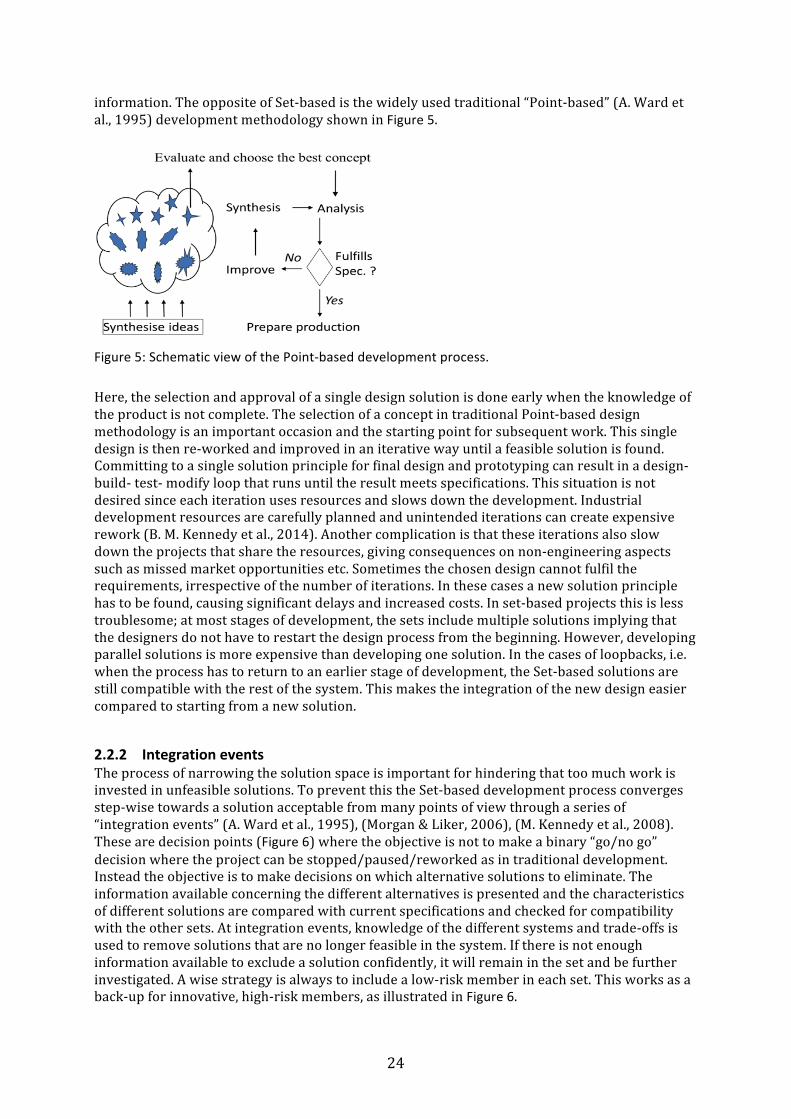
2.2.2 Integration events The process of narrowing the solution space is important for hindering that too much work is invested in unfeasible solutions. To prevent this the Set-‐based development process converges step-‐wise towards a solution acceptable from many points of view through a series of “integration events” (A. Ward et al., 1995), (Morgan & Liker, 2006), (M. Kennedy et al., 2008). These are decision points (Figure 6) where the objective is not to make a binary “go/no go” decision where the project can be stopped/paused/reworked as in traditional development. Instead the objective is to make decisions on which alternative solutions to eliminate. The information available concerning the different alternatives is presented and the characteristics of different solutions are compared with current specifications and checked for compatibility with the other sets. At integration events, knowledge of the different systems and trade-‐offs is used to remove solutions that are no longer feasible in the system. If there is not enough information available to exclude a solution confidently, it will remain in the set and be further investigated. A wise strategy is always to include a low-‐risk member in each set. This works as a back-‐up for innovative, high-‐risk members, as illustrated in Figure 6.
25
Figure 6: Schematic view of the SBCE narrowing process.
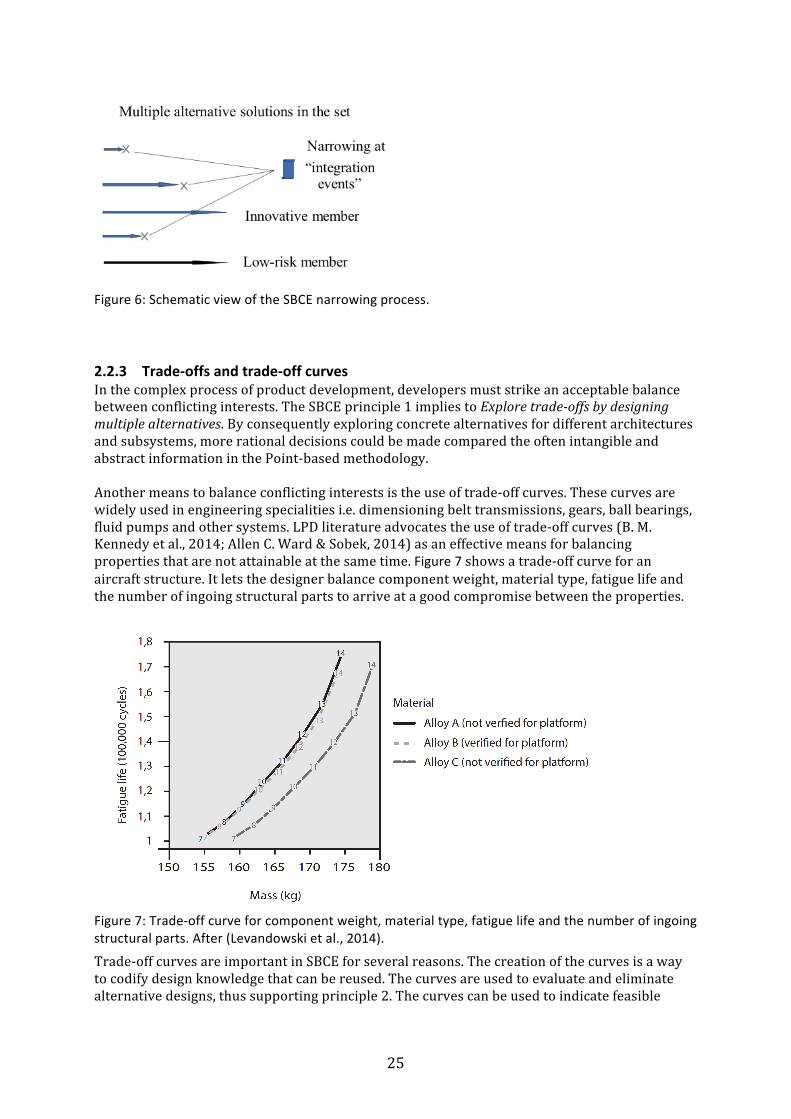
2.2.3 Trade-‐offs and trade-‐off curves In the complex process of product development, developers must strike an acceptable balance between conflicting interests. The SBCE principle 1 implies to Explore trade-‐offs by designing multiple alternatives. By consequently exploring concrete alternatives for different architectures and subsystems, more rational decisions could be made compared the often intangible and abstract information in the Point-‐based methodology. Another means to balance conflicting interests is the use of trade-‐off curves. These curves are widely used in engineering specialities i.e. dimensioning belt transmissions, gears, ball bearings, fluid pumps and other systems. LPD literature advocates the use of trade-‐off curves (B. M. Kennedy et al., 2014; Allen C. Ward & Sobek, 2014) as an effective means for balancing properties that are not attainable at the same time. Figure 7 shows a trade-‐off curve for an aircraft structure. It lets the designer balance component weight, material type, fatigue life and the number of ingoing structural parts to arrive at a good compromise between the properties.
Figure 7: Trade-‐off curve for component weight, material type, fatigue life and the number of ingoing structural parts. After (Levandowski et al., 2014).
Trade-‐off curves are important in SBCE for several reasons. The creation of the curves is a way to codify design knowledge that can be reused. The curves are used to evaluate and eliminate alternative designs, thus supporting principle 2. The curves can be used to indicate feasible

26
regions of the design space as well as communicating what is possible to obtain, thereby supporting principle 1.
2.2.4 The specification management process of Set-‐ based Concurrent Engineering The management of specifications is an important feature of SBCE, aiming at an optimal system design rather than an optimization of components under fixed constraints. Initially, SBCE specifications are not fixed numbers but rather a range of upper and lower limits representing design specifications (Durward K. Sobek et al., 1999; Allen C. Ward & Sobek, 2014). The approach eliminates the need for a complete specification at the start of a project. The SBCE decision method does not include a pre-‐determined number of steps and can be used regardless of the state of development or maturity of the technical system. The convergence of the evolving design is controlled by adding more constraints and by narrowing the specifications.
2.2.5 Industrial applications of Set-‐ based Concurrent Engineering The emerging interest for SBCE may suggest that it is a new concept, but in the early 20th century, the Wright brothers employed a strategy that could be characterised as Set-‐based (B. M. Kennedy et al., 2014). The similarities to Set-‐based design are that the Wrights designed and evaluated the performance of different sets of design solutions to identify the critical parameters, before committing to a specific design. To be successful, the trade-‐offs between the propellers, wing profiles, engine and control system must all be well balanced and orchestrated. One example is the design of propellers. In spite of their inferior resources (B. M. Kennedy et al., 2014) the Wrights propellers had a near optimal design for the application that was superior to their competitors’ designs (Ash, 2003), which relied on heuristics for steam-‐boat propellers. The Wright propellers were shaped by knowledge of the critical design parameters obtained from wind tunnel tests. With these data, they could make trade-‐offs between propulsion, air speed and propeller speed, and match the propellers to the set of possible wing profiles and engine/transmission configurations. More recently, other authors have used optimisations methods inspired by SBCE (Finch & Ward, 1997). Also simulations of the communication between engineers have been investigated, to compare the effectiveness of a Set-‐based design process with traditional processes. Shahan and Seepersad (2010) found that a Set-‐based approach increase the probability of identifying satisfactory designs compared to a Point-‐based process. In some cases SBCE research is done in cooperation with industry, but only evaluation of single SBCE principles has been recorded. One article (Madhavan et al., 2008) uses input from industry to model and optimise a product and thereby apply parts of SBCE in the form of multiple solutions and broad specifications. There are also larger studies of related industrial implementations in the Lean Aerospace Initiative (McManus, Haggerty, & Murman, 2007). According to Morgan and Liker (2006), Allen C. Ward and Sobek (2014) and M. Kennedy et al. (2008), SBCE is a central component of the Lean Product Development (LPD) framework. However, in the primary studies (A. Ward et al., 1995), SBCE contained a majority of the features that are now considered the core of LPD. The Lean Aerospace Initiative studies do not address the same questions as the SBCE principles, rather a translation of lean manufacturing principles to the domain of development. The LeanPPD project (Al-‐Ashaab et al., 2013) involved several industrial and academic partners throughout Europe. The authors present a design process based on SBCE and evaluate it in a pilot project in an aerospace company. One part of the methodology is to use a Pugh matrix to select the best concept, which is rather Point-‐based. The participating engineers, however, appreciate the overall approach. In the construction industry, Parrish investigated a set-‐based design approach to reinforcing concrete structures (Parrish, 2009). Parrish explores multiple designs and postpones the
27
commitment to a specific design. Also the communication of designs between different stakeholders is discussed, but the thesis does not explore other important features such as Set-‐based decisions. For platform development, Michaelis et al. (2013) present an integrated model for product and manufacturing system platforms inspired by SBCE. Moreover, Levandowski et al. (2014) continues that work by elaborating the model and outlines a process for its application. The approach is illustrated by an industrial case.
2.3 Popular decision methods in design Decision-‐making and selection of different design alternatives is a central activity in the product development process. A closer look at the Set-‐based decision process can be found in Paper B. In this section, some popular decision methods are presented. On an abstract level, the aim of decision methods is to identify a solution that fulfils customers’, users’ and other stakeholders’ interests in order to select the most promising alternatives to spend resources on. Unfortunately, this is a Catch-‐22 situation: it is not possible to make decisions based on the performance of a particular design until the degree of detail is sufficiently high, but these details are not possible to assess unless numerous decisions are made. Popular selection methods such as Pugh’s method for controlled convergence (Pugh, 1991) , Kesselring´s selection matrix (Kesselring, 1951), address this problem by a structured use of the knowledge at the current level of refinement. This knowledge is used to forecast the characteristics and performance of future designs in order to select the most promising one. Other ways to evaluate designs presented in this section are the Set-‐based decision process and Suh’s axiom for selecting the best design (Suh, 1990).
2.3.1 The decision process of Set-‐ Based Concurrent Engineering The decision process of Set-‐Based Concurrent Engineering is sometimes described as delaying decisions until enough information is available (A. Ward et al., 1995). In this aspect, it can be characterised as slow, a quality usually considered a negative impact on development speed, but at the same time described as very efficient. A Set-‐Based process offers a different approach to the selection methods found in popular textbooks (G. Pahl, Beitz, W., et al. , 2007; Pugh, 1991; Ullman, 2009; Ulrich & Eppinger, 2012). It uses the mechanism of excluding solutions that are incompatible and not capable of operating in combination with other elements in a system (A. Ward et al., 1995; Allen C. Ward & Sobek, 2014). The Point-‐based approach, in this thesis represented by Pugh’s method Pugh, 1991, makes selection and approval of specific product solutions early when the knowledge is incomplete. The set-‐based approach is somewhat the opposite of this; Instead of selecting the most promising solutions, the impossible solutions are rejected. In practice, this is an elimination of solutions that are proven unfeasible according to relevant criteria at the current state of development. The set-‐based approach resembles methods used in the early phases of development, such as the exclusion method (Roozenburg & Eekels, 1995). It also resembles the elimination matrix (G. Pahl, Beitz, W., et al. , 2007; Ullman, 2009). The elimination matrix is, however, a concept selection tool used to judge intuitively whether a concept should be eliminated or not. The concepts are evaluated against a set of generic criteria including the perceived ability to meet the requirements. The elimination matrix is not concerned with the compatibility between concepts or between individual design solutions in different concepts. The logical robustness of the rejection approach is appealing since the consequences of incorrect choices are rather small. If a designer uses a selection method promoting the second best
28
solution as the candidate for industrialization instead of the best it is much more critical than excluding the second worst solution instead of the worst. Another aspect is the efficiency of the SBCE decision process: choosing alternatives requires detailed knowledge of the different alternatives in order to rank the different concepts correctly. Contrary to the selection of one alternative, elimination can be done confidently from incomplete information. The process of eliminating solutions is therefore less exhaustive compared to the selection process.
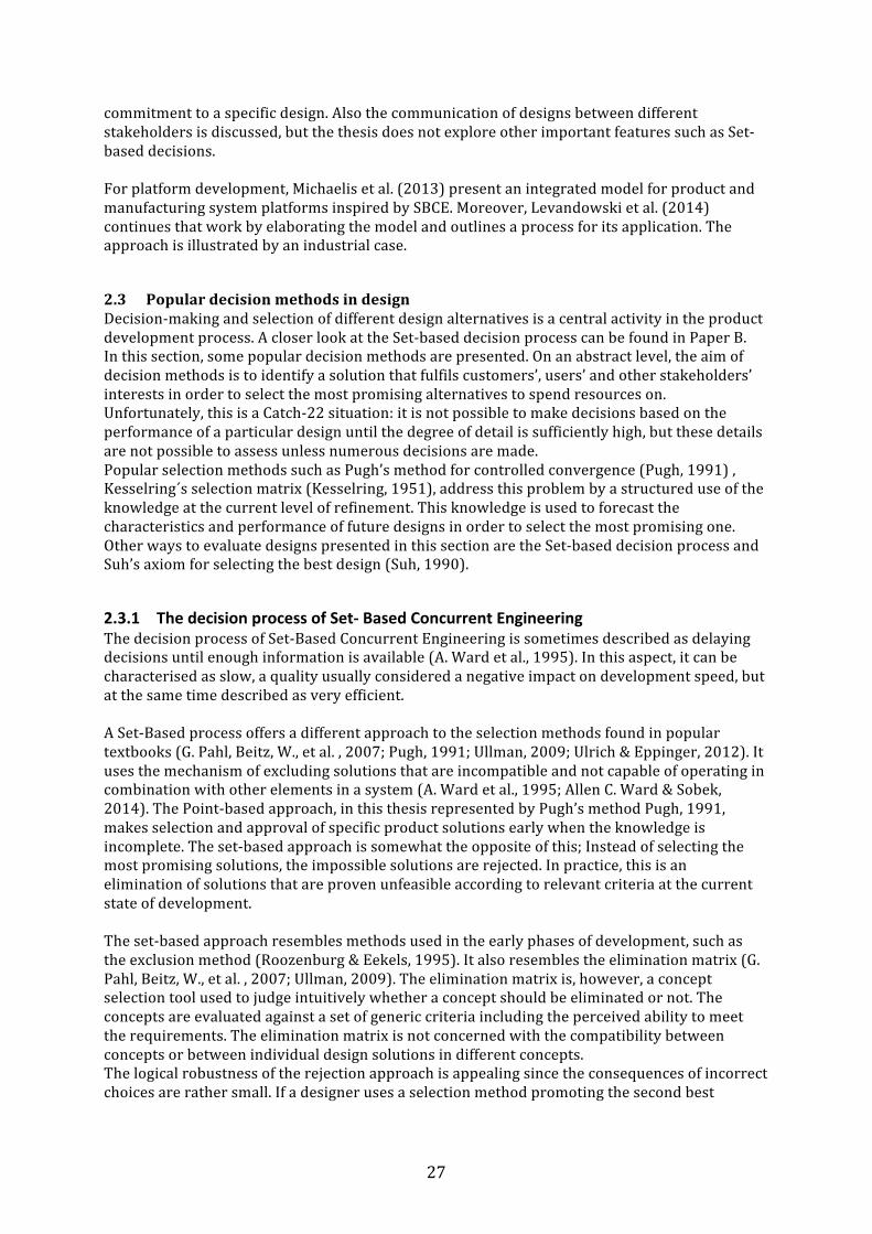
2.3.2 Pugh and Kesselring’s matrix selection methods for comparing different solutions. Pugh’s method for controlled convergence (Pugh et al., 1996) and Kesselring´s selection matrix (Kesselring, 1951) are well known methods for design evaluations. For the purposes of this thesis, only the main characteristics are presented, detailed descriptions on how to use them can be found in textbooks and research papers. Usually, Pugh’s method is used earlier in the design process to select the alternatives to use in the more advanced Kesselring evaluation. Both methods are decision matrixes aimed at selecting the most promising design among a set of alternatives. To make the decisions more objective, each individual property of a design is compared to the same properties of the other designs, instead of comparing one complete alternative versus another. Pugh’s method is relative and uses a datum, a reference solution, together with three criteria: better “+”, same “S” or worse “-‐” than the datum, see Table 1. The relative comparison between individual properties of the design alternatives and the datum is an important feature of the method, since it is easier for humans to compare a solution to a datum, than to evaluate a score. Table 1: One version of the Pugh selection matrix. After (Pugh et al., 1996).
Concept 1 Concept 2 Concept 3 Criterion 1 D S + Criterion 2 A -‐ + Criterion 3 T + S Criterion 4 U -‐ -‐ Criterion 5 M + S No. of + 2 2 No. of -‐ 2 1 No. of S 1 2 The evaluation process is a comparison in pairs of the individual attributes of each design solution to the corresponding attributes of the datum. The result is often summarized into a score, a single number representing the quality of each design (Ullman, 2009; Ulrich & Eppinger, 2012). Ideally, the best alternative corresponds to the best scores. However, this is not the way Pugh describes the method. The “+” and “-‐” are not to be arithmetically summarised since their strengths and characters are different. The matrix should instead provide a base for discussion on design evaluation rather than pointing out the best solution. The matrix shows the strengths and weaknesses of different concepts and serves as a guideline to which concepts to improve in an iterative process. Kesselring’s method compares each different design alternative to a set of evaluation criteria. Each evaluation criteria is given a weight factor or importance. Then each design alternative is graded on a pre-‐defined scale on its ability to fulfil each criterion. The merit value for the
29
individual design solution is the sum of the weight factor of each criteria multiplied with the grades of the corresponding property of each design alternative. The design alternative having the highest merit value is considered the best alternative. Before using Pugh’s or Kesselring’s methods, preparations are needed. The process is not straight-‐forward since it relies on human judgment rather than hard facts. One issue is how to obtain the properties of a future technical system without designing, building or simulating it first. Many decision supporting methods have also another important drawback: In spite of a sound logical or empirical foundation, important input to the decision process is subjective and based on personal preferences. It is often expressed in the form of estimates of customer requirements or ranking the importance of different product properties.
2.3.3 Design decisions based on axioms In the context of design decisions, Axiomatic design (Suh, 1990) presents a different approach compared to using subjective evaluations of future performance of proposed solutions. The Axiomatic design methodology offers a toolbox for systematic analysis of the interdependence between customer needs, functional requirements, design parameters and process variables. The theory however, does not provide a process for how to fulfil the axioms. Axiomatic design is founded in two axioms: the Independence axiom and the Information axiom. The Independence axiom states that a design should satisfy the functional requirements and constraints without introducing a coupling of functions. In a good design, the individual design parameter can be adjusted to satisfy its corresponding functional requirement without affecting the fulfilment of other functional requirements. For design decisions, the Information axiom states that the best design has the lowest amount of information. Information is a measure of complexity and this quality is used to select between designs that all satisfy the Independence axiom. In this sense, Axiomatic design resembles the guideline “simplicity” from G. Pahl, Beitz, W., et al. (2007)since it encourages reducing the complexity of the design. Also, the use of the Information axiom resembles the Set-‐based decision process, since both use facts about the designs to eliminate inferior solutions rather than estimations. The use of Axiomatic design, however, is again a Catch-‐22 situation: to calculate the level of information, concrete designs are needed, and to obtain concrete designs, design decisions have to be made. This implies that the approach in practice differs little from other selection methods, especially in the first stages of development.
2.4 The role of knowledge management The importance of knowledge management is obvious in all development paradigms, since the engineers use their knowledge to create new products and processes. Not surprisingly, the role of knowledge is emphasised by several authors of LPD books, devoting principles and cornerstones to knowledge management. Knowledgeable employees and re-‐use of knowledge is a central part in the frameworks of Morgan, Kennedy, Ward, and Sobek. There are also tools for storing codified knowledge that are commonly used in Lean contexts, such as the A3-‐report (Morgan & Liker, 2006). The authors above give two principal means to improve knowledge management:
• Knowledge resides in the engineers becoming experts on their jobs. This expertise is carefully fostered by the organization that recognizes the value of knowledgeable employees.
30
• Knowledge is codified and structured into written information. In this form, it can be stored, retrieved and re-‐used by the employees. The organization recognizes the value of codified knowledge and dedicates resources to create and maintain it.
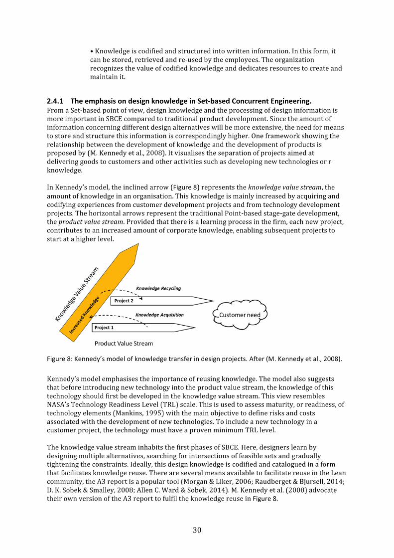
2.4.1 The emphasis on design knowledge in Set-‐based Concurrent Engineering. From a Set-‐based point of view, design knowledge and the processing of design information is more important in SBCE compared to traditional product development. Since the amount of information concerning different design alternatives will be more extensive, the need for means to store and structure this information is correspondingly higher. One framework showing the relationship between the development of knowledge and the development of products is proposed by (M. Kennedy et al., 2008). It visualises the separation of projects aimed at delivering goods to customers and other activities such as developing new technologies or r knowledge. In Kennedy’s model, the inclined arrow (Figure 8) represents the knowledge value stream, the amount of knowledge in an organisation. This knowledge is mainly increased by acquiring and codifying experiences from customer development projects and from technology development projects. The horizontal arrows represent the traditional Point-‐based stage-‐gate development, the product value stream. Provided that there is a learning process in the firm, each new project, contributes to an increased amount of corporate knowledge, enabling subsequent projects to start at a higher level.
Figure 8: Kennedy’s model of knowledge transfer in design projects. After (M. Kennedy et al., 2008).
Kennedy’s model emphasises the importance of reusing knowledge. The model also suggests that before introducing new technology into the product value stream, the knowledge of this technology should first be developed in the knowledge value stream. This view resembles NASA’s Technology Readiness Level (TRL) scale. This is used to assess maturity, or readiness, of technology elements (Mankins, 1995) with the main objective to define risks and costs associated with the development of new technologies. To include a new technology in a customer project, the technology must have a proven minimum TRL level. The knowledge value stream inhabits the first phases of SBCE. Here, designers learn by designing multiple alternatives, searching for intersections of feasible sets and gradually tightening the constraints. Ideally, this design knowledge is codified and catalogued in a form that facilitates knowledge reuse. There are several means available to facilitate reuse in the Lean community, the A3 report is a popular tool (Morgan & Liker, 2006; Raudberget & Bjursell, 2014; D. K. Sobek & Smalley, 2008; Allen C. Ward & Sobek, 2014). M. Kennedy et al. (2008) advocate their own version of the A3 report to fulfil the knowledge reuse in Figure 8.
31
In addition to the approaches above, this thesis has bearing on the reuse of design knowledge that can be achieved by functional models. These represent a concise body of knowledge about designs of technical systems and their rationale and are further discussed in the section below.
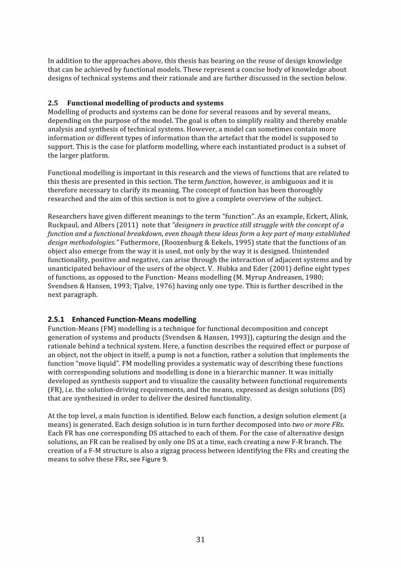
2.5 Functional modelling of products and systems Modelling of products and systems can be done for several reasons and by several means, depending on the purpose of the model. The goal is often to simplify reality and thereby enable analysis and synthesis of technical systems. However, a model can sometimes contain more information or different types of information than the artefact that the model is supposed to support. This is the case for platform modelling, where each instantiated product is a subset of the larger platform. Functional modelling is important in this research and the views of functions that are related to this thesis are presented in this section. The term function, however, is ambiguous and it is therefore necessary to clarify its meaning. The concept of function has been thoroughly researched and the aim of this section is not to give a complete overview of the subject. Researchers have given different meanings to the term “function”. As an example, Eckert, Alink, Ruckpaul, and Albers (2011) note that ”designers in practice still struggle with the concept of a function and a functional breakdown, even though these ideas form a key part of many established design methodologies.” Futhermore, (Roozenburg & Eekels, 1995) state that the functions of an object also emerge from the way it is used, not only by the way it is designed. Unintended functionality, positive and negative, can arise through the interaction of adjacent systems and by unanticipated behaviour of the users of the object. V. Hubka and Eder (2001) define eight types of functions, as opposed to the Function-‐ Means modelling (M. Myrup Andreasen, 1980; Svendsen & Hansen, 1993; Tjalve, 1976) having only one type. This is further described in the next paragraph.
2.5.1 Enhanced Function-‐Means modelling Function-‐Means (FM) modelling is a technique for functional decomposition and concept generation of systems and products (Svendsen & Hansen, 1993)), capturing the design and the rationale behind a technical system. Here, a function describes the required effect or purpose of an object, not the object in itself; a pump is not a function, rather a solution that implements the function “move liquid”. FM modelling provides a systematic way of describing these functions with corresponding solutions and modelling is done in a hierarchic manner. It was initially developed as synthesis support and to visualize the causality between functional requirements (FR), i.e. the solution-‐driving requirements, and the means, expressed as design solutions (DS) that are synthesized in order to deliver the desired functionality. At the top level, a main function is identified. Below each function, a design solution element (a means) is generated. Each design solution is in turn further decomposed into two or more FRs. Each FR has one corresponding DS attached to each of them. For the case of alternative design solutions, an FR can be realised by only one DS at a time, each creating a new F-‐R branch. The creation of a F-‐M structure is also a zigzag process between identifying the FRs and creating the means to solve these FRs, see Figure 9.
32
Figure 9: Example of an F-‐M model representing several alternative overall concepts (adapted from (Svendsen & Hansen, 1993)).
One important aspect is that any effective functional decomposition requires casual links or relations between functions and means. These are mutually dependent and different choices of design solutions render different subsequent functional requirements and different corresponding functional couplings. This is a clear distinction from a traditional breakdown of requirements, which is subsequently decomposed into sub-‐ requirements without considering the ways requirements are embodied. It is also contrasts the view that functions can be used to create meaningful structures independent of the designed artefact, as presented by G. Pahl et al. (2007) p.32. FM-‐ modelling has been extended by combining it with the so-‐called ‘chromosome model’ and by adding modelling elements that captures design history, objectives and constraints (Malmqvist, 1997). A further enhancement of function-‐means trees is the object-‐ oriented view presented by Schachinger and Johannesson (2000) clarifying how constraints are decomposed and how accompanying design information can be adhered to the models in the same hierarchical model. Schachinger and Johannesson (2000) point out that this Enhanced F-‐M modelling follows a representational formalism that is consistent with the independence axiom of Axiomatic design (Suh, 1990). Suh claims that a good design must be uncoupled, which implies that only one DS is allowed to solve the superior FR. It also implies that a DS must not affect the ability to fulfil the functional requirements governing a parallel FR.
2.5.2 Manufacturing oriented and development oriented platforms Platform-‐based design has received positive attention for its efficiency and there is a vast body of knowledge in platforms. Jiao et al. (2007) conclude that there are two dominant views on the concept of platforms. The first considers a platform the physical collection of components shared by several products. Here, the combination of different components enables a variety of products, while keeping the number of individual components low, thus creating economics of scale in manufacturing. The second view is that a platform is a common structure from which new products can be derived (instantiated). Additionally, Zhang (2015) identifies five more types than the two considered above. These types are exemplified by multibranded platforms, process platforms, flexible platforms, layout platforms and function-‐technology platforms.
Function
Two alternative means to realize a function
Two necessary functions required if means is chosen
Means Possible overall concept
33
The most commonly described platforms are manufacturing oriented types having components that are reusable in a several products (Jiao et al., 2007). These component-‐based platforms are motivated by the benefits of scale in manufacturing and are often created and prepared by studying the components and structures of existing products. One example of such platform preparation methodology is given by Hvam, Mortensen, and Riis (2008) where the process begins with an analysis of the current physical product families. From the prepared platform, derivative products are configured and the platform must accommodate sufficient differentiating features to satisfy the different needs of the market. One challenge is to identify the optimal common product elements that could form the basis for the platform. This challenge is described by (Whitney, 1993 ) before the term platform was commonly used. He presents detailed examples of how the firm Nippondenso can offer large product families by combining a limited set of base components that are also adapted for cost efficient automatic production. To set up the production, Nippondenso designs the components specifically for automatic production and also designs specialised manufacturing equipment. In this example the designed base components are one example of reusable assets. Robertson and Ulrich (1998) define platforms as ”the collection of assets that are shared by a set of products”. Nippondensos’ knowledge of integrating design and manufacturing could therefore be regarded as an asset provided that it could be shared, i.e. could be reused. This type of assets are commonly implemented in a development-‐oriented platform strategy or a development platform (Levandowski, 2014). These focuses on the economics of scale in product development and reuses other things than physical parts such as functions, design knowledge etc. Development platforms are important for companies that cannot achieve the economics of scale offered by manufacturing oriented platforms such as engineer-‐to-‐order firms or industry with low production volumes. This thesis focuses on improving development processes and consequently concentrates on development platforms.
2.5.3 Theory of Domains The theory of domains was introduced by M. Myrup Andreasen (1980). The model identifies four different types of systems structures, i.e. domains, in the design of a system. The domains are the Process, Function, Organ and the Constructional domains. The theory was revised (M. Myrup Andreasen, 1998) by merging the process and function domains into the Transformation Domain. In this thesis, the initial model is more suitable as it has a separate domain for functions. Processes and operations are described in the Process domain. The Functional domain defines what the product does and the organs that realize these functions are found in the Organ domain. Finally, the physical components that build up the product are found in the Constructional domain. The model shows how abstract functional structures relate to physical structures and how these structures may be related. The theory of Domains can represent different types of information created during a development process in the same way as a F-‐M tree can hold abstract and concrete information about functional requirements and design solutions. Each domain is described as a two dimensional space: The first dimension relates to the understanding of the solutions to a design problem, ranging from an abstract to a concrete understanding. The second dimension relates to the description of the solutions from a low to a high level of detail, see Figure 10.

34
Figure 10: The four domains of design with gradual change in concretisation and detailing. After M. Myrup Andreasen (1980).
The model suggests that in order to arrive at a full understanding of the design solution, no field should be left blank. The designers work between domains and zigzag between simple and abstract representations through different levels of complexity. By being more concrete and closing the gaps in the model, the process generates knowledge in the different domains and in that sense it resembles the Set-‐based process. However, the approach is not intended for designing multiple alternatives. Reflecting on the relation between the theory of Domains and F-‐M trees, it is evident that the design solutions of the F-‐M tree correspond to the organ domain with its physical embodiment in the constructional domain. The theory of Domains can therefore be useful when constructing an F-‐M tree. A function can only be realised by a specific design solution (Suh, 1990). Several design solutions can, however, be integrated into one shared physical component, as well as the opposite case where function is provided by the combination of different components. Figure 11 shows the case where several design solutions are integrated into one shared component.
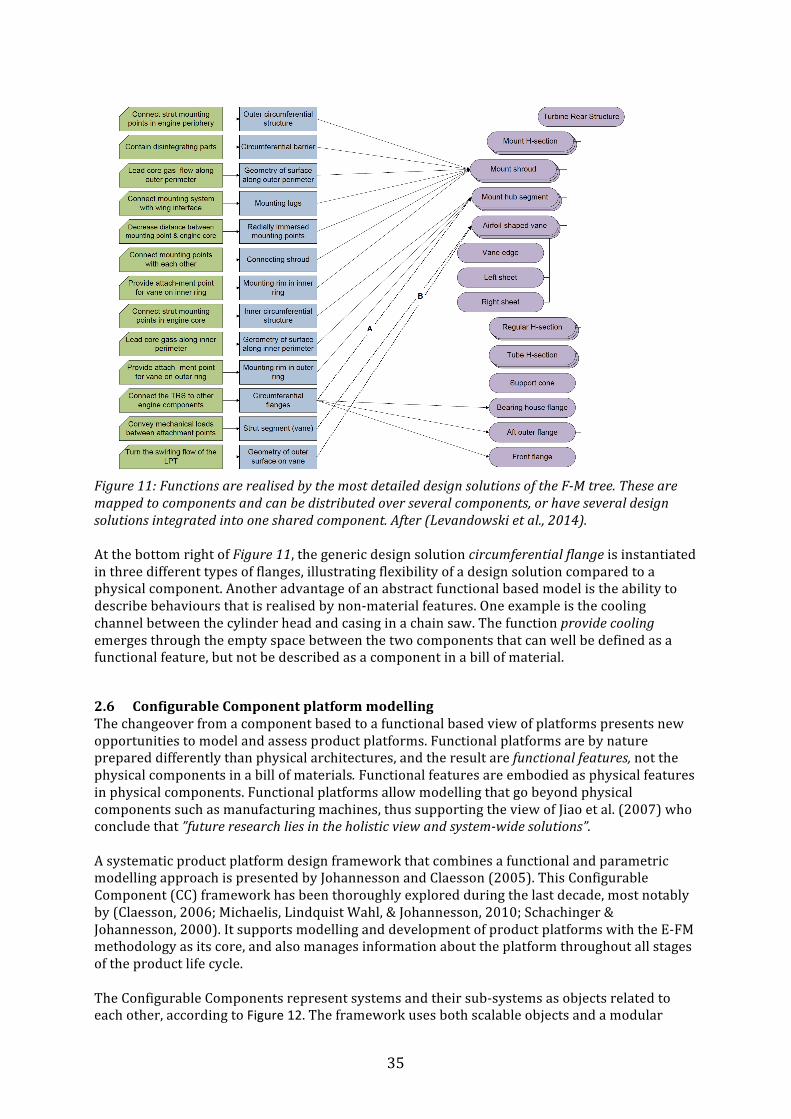
35
Figure 11: Functions are realised by the most detailed design solutions of the F-‐M tree. These are mapped to components and can be distributed over several components, or have several design solutions integrated into one shared component. After (Levandowski et al., 2014). At the bottom right of Figure 11, the generic design solution circumferential flange is instantiated in three different types of flanges, illustrating flexibility of a design solution compared to a physical component. Another advantage of an abstract functional based model is the ability to describe behaviours that is realised by non-‐material features. One example is the cooling channel between the cylinder head and casing in a chain saw. The function provide cooling emerges through the empty space between the two components that can well be defined as a functional feature, but not be described as a component in a bill of material.
2.6 Configurable Component platform modelling The changeover from a component based to a functional based view of platforms presents new opportunities to model and assess product platforms. Functional platforms are by nature prepared differently than physical architectures, and the result are functional features, not the physical components in a bill of materials. Functional features are embodied as physical features in physical components. Functional platforms allow modelling that go beyond physical components such as manufacturing machines, thus supporting the view of Jiao et al. (2007) who conclude that ”future research lies in the holistic view and system-‐wide solutions”. A systematic product platform design framework that combines a functional and parametric modelling approach is presented by Johannesson and Claesson (2005). This Configurable Component (CC) framework has been thoroughly explored during the last decade, most notably by (Claesson, 2006; Michaelis, Lindquist Wahl, & Johannesson, 2010; Schachinger & Johannesson, 2000). It supports modelling and development of product platforms with the E-‐FM methodology as its core, and also manages information about the platform throughout all stages of the product life cycle. The Configurable Components represent systems and their sub-‐systems as objects related to each other, according to Figure 12. The framework uses both scalable objects and a modular
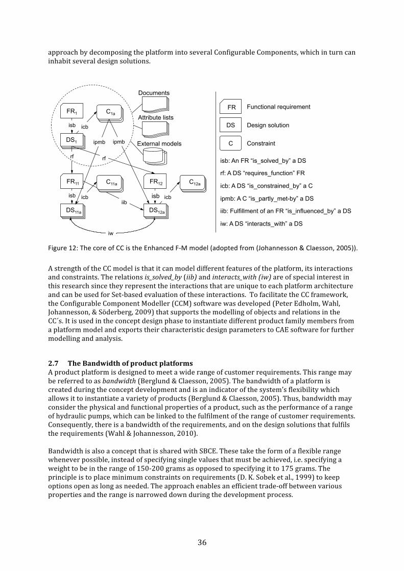
36
approach by decomposing the platform into several Configurable Components, which in turn can inhabit several design solutions.
Figure 12: The core of CC is the Enhanced F-‐M model (adopted from (Johannesson & Claesson, 2005)).
A strength of the CC model is that it can model different features of the platform, its interactions and constraints. The relations is_solved_by (iib) and interacts_with (iw) are of special interest in this research since they represent the interactions that are unique to each platform architecture and can be used for Set-‐based evaluation of these interactions. To facilitate the CC framework, the Configurable Component Modeller (CCM) software was developed (Peter Edholm, Wahl, Johannesson, & Söderberg, 2009) that supports the modelling of objects and relations in the CC´s. It is used in the concept design phase to instantiate different product family members from a platform model and exports their characteristic design parameters to CAE software for further modelling and analysis.
2.7 The Bandwidth of product platforms A product platform is designed to meet a wide range of customer requirements. This range may be referred to as bandwidth (Berglund & Claesson, 2005). The bandwidth of a platform is created during the concept development and is an indicator of the system’s flexibility which allows it to instantiate a variety of products (Berglund & Claesson, 2005). Thus, bandwidth may consider the physical and functional properties of a product, such as the performance of a range of hydraulic pumps, which can be linked to the fulfilment of the range of customer requirements. Consequently, there is a bandwidth of the requirements, and on the design solutions that fulfils the requirements (Wahl & Johannesson, 2010). Bandwidth is also a concept that is shared with SBCE. These take the form of a flexible range whenever possible, instead of specifying single values that must be achieved, i.e. specifying a weight to be in the range of 150-‐200 grams as opposed to specifying it to 175 grams. The principle is to place minimum constraints on requirements (D. K. Sobek et al., 1999) to keep options open as long as needed. The approach enables an efficient trade-‐off between various properties and the range is narrowed down during the development process.
FR1
DS1
C1a
isb icb
FR11
DS11a
C11a
isb icb
FR12
DS12a
C12a
isb icb
rf rf
ipmb ipmb
iib
iw
Documents
Attribute lists
External models
isb: An FR “is_solved_by” a DS
rf: A DS “requires_function” FR
icb: A DS “is_constrained_by” a C
ipmb: A C “is_partly_met-by” a DS
iib: Fulfillment of an FR “is_influenced_by” a DS
iw: A DS “interacts_with” a DS
FR Functional requirement
DS Design solution
C Constraint
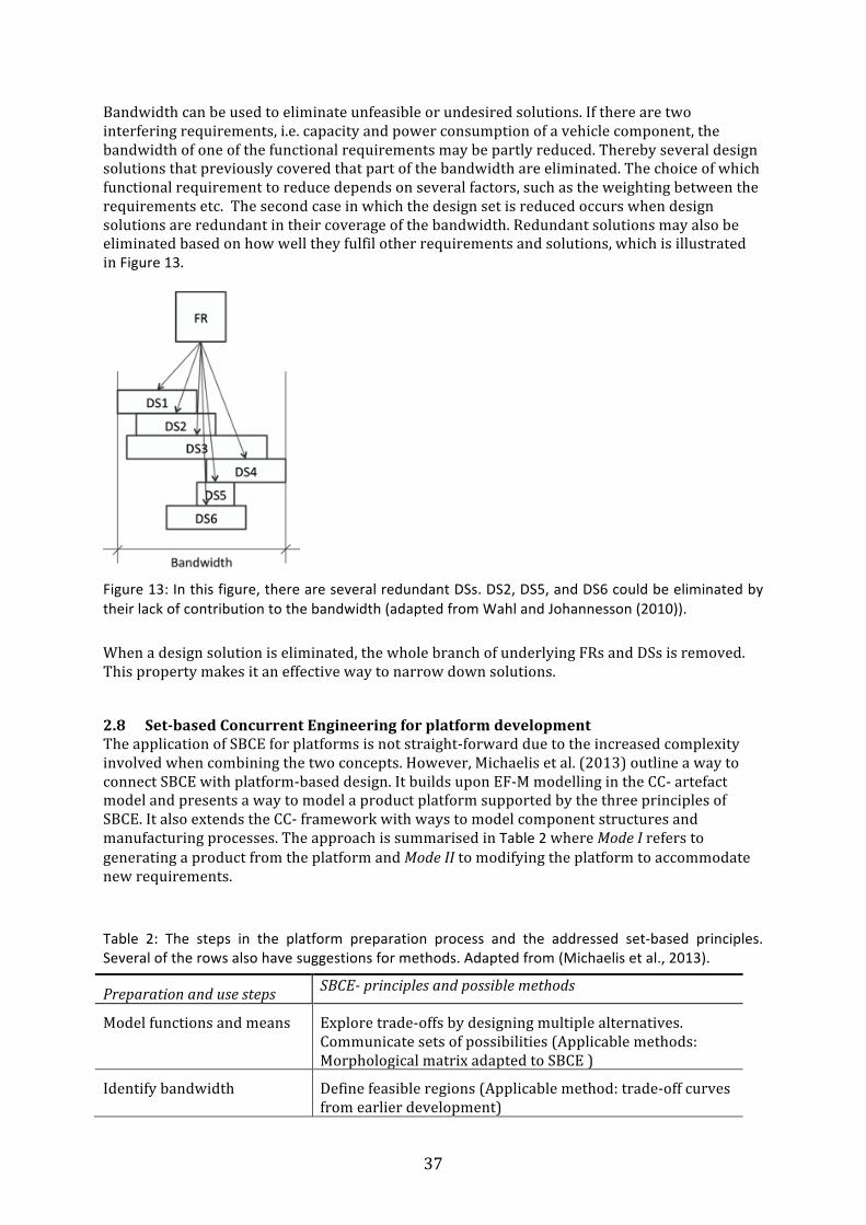
37
Bandwidth can be used to eliminate unfeasible or undesired solutions. If there are two interfering requirements, i.e. capacity and power consumption of a vehicle component, the bandwidth of one of the functional requirements may be partly reduced. Thereby several design solutions that previously covered that part of the bandwidth are eliminated. The choice of which functional requirement to reduce depends on several factors, such as the weighting between the requirements etc. The second case in which the design set is reduced occurs when design solutions are redundant in their coverage of the bandwidth. Redundant solutions may also be eliminated based on how well they fulfil other requirements and solutions, which is illustrated in Figure 13.
Figure 13: In this figure, there are several redundant DSs. DS2, DS5, and DS6 could be eliminated by their lack of contribution to the bandwidth (adapted from Wahl and Johannesson (2010)).
When a design solution is eliminated, the whole branch of underlying FRs and DSs is removed. This property makes it an effective way to narrow down solutions.
2.8 Set-‐based Concurrent Engineering for platform development The application of SBCE for platforms is not straight-‐forward due to the increased complexity involved when combining the two concepts. However, Michaelis et al. (2013) outline a way to connect SBCE with platform-‐based design. It builds upon EF-‐M modelling in the CC-‐ artefact model and presents a way to model a product platform supported by the three principles of SBCE. It also extends the CC-‐ framework with ways to model component structures and manufacturing processes. The approach is summarised in Table 2 where Mode I refers to generating a product from the platform and Mode II to modifying the platform to accommodate new requirements. Table 2: The steps in the platform preparation process and the addressed set-‐based principles. Several of the rows also have suggestions for methods. Adapted from (Michaelis et al., 2013).
Preparation and use steps SBCE-‐ principles and possible methods
Model functions and means Explore trade-‐offs by designing multiple alternatives. Communicate sets of possibilities (Applicable methods: Morphological matrix adapted to SBCE )
Identify bandwidth Define feasible regions (Applicable method: trade-‐off curves from earlier development)
38
Identify interactions Look for intersections of feasible sets
Model configurable com-‐ponents
Communicate sets of possibilities
Validate the design space for Mode I
Establish feasibility before commitment(Applicable methods: design space exploration, trade-‐off curves, multi-‐criteria optimization, physical testing and worst-‐case scenarios )
Platform execution (Mode I) Establish feasibility before commitment (Applicable methods: trade-‐off curves and preference set-‐based design).
This work is extended by Levandowski et al. (2014) by further developing the CC-‐framework and suggesting a platform preparation process for SBCE. The process is illustrated by modelling an example from the aerospace industry and its corresponding manufacturing system. The process uses trade-‐off curves to make decisions on which technology to pursuit if the bandwidth of the platform is to be expanded. The proposed model also helps to trace the propagation of changes introduced in the product or the manufacturing system to prevent unanticipated effects in the platform.
2.9 Modelling and evaluating functional product platform concepts The Configurable Component framework has been used to model product and manufacturing systems and their respective subsystems inspired by Set-‐based principles (Michaelis, 2013). To further apply the support offered by the principles of SBCE also for platforms, multiple platform concepts must be considered and evaluated efficiently. Regardless of which platform model is used, conceiving a product platform requires a massive workload compared to development of single products. Designing multiple alternative platforms to a high level of detail is therefore not feasible from a resource and lead-‐time perspective and methods to evaluate platform concepts before embodiment are therefore needed Michaelis et al. (2013) and Levandowski et al. (2014) present ways to model platforms in different life cycles. The work focuses on the preparation of platforms and corresponding manufacturing system, and uses aircraft components to exemplify the approach. The evaluation of the platform models is done by eliminating unfeasible alternatives and by using trade-‐off curves. Moreover, manufacturing alternatives can to some extent be evaluated in the preparation process, thereby ensuring feasibility of the design space before commitment to a design. Bonjour, Deniaud, and Micaelli (2012) combine the component based view and functional view of platforms and propose a methodology to evaluate both the physical architecture and the functional architecture for alternative systems. In the view of F-‐M modelling, it is evident that the proposed functions are rather Design Solutions than Functional Requirements. Their method analyses the consistency between the suggested system components and the corresponding functional architecture in order to divide and arrange the physical architecture into relevant modules by using couplings between functions and components. The quantity of couplings is a measure of the complexity of a system. Suh (1990) states in the Axiomatic design theory that the design with the lowest degree of functional couplings is preferable. Here, term functional coupling is referring only to interactions where a chosen solution negatively affects the ability to fulfil the functional requirements governing a parallel functional requirement (Suh, 1990) (Johannesson, 1996). In the CC framework the is_solved_by
39
relations represents the functional couplings. These could therefore be used to compare platform concepts based on a CC-‐model in a similar way as (Bonjour et al., 2012).
2.10 Change propagation Method The components and modules of a system interact with each other through its physical and functional couplings. A change to one part of a system may therefore require changes to other parts, which in turn can initiate a flow of unwanted changes that propagates through the system. Clarkson, Simons, and Eckert (2004) present the Change Propagation Method (CPM), that can predict this propagation for mature designs. By breaking down a model of the product into sub-‐systems, the risk of change propagation can be calculated. CPM analyses the connections between the components and sub-‐systems and converts these to entries in a Design Structure Matrix (DSM) (Steward, 1981). The magnitude of propagation depends on the context of the design change. The method uses two concepts to capture this: the change multiplier or the change absorber. The change absorber can accommodate changes to some degree but will ultimately pass this change on to other parts when it becomes too extensive. The CPM method has been extended also to incorporate a function–behaviour–structure (Hamraz, Caldwell, Ridgman, & Clarkson, 2015). This also includes considering the behaviour and the functions of the system as opposed to only analysing the structure and its physical components. To support functional modelling with CPM, the interacts_with relations of the CC-‐model represent the same connections as are used in CPM and could therefore be used to populate the DSM matrix. These could then be used to compare and rule out platform concepts that are sensitive to changes and disturbances based on the CPM analysis.
2.11 Concluding summary The following conclusion can be drawn from the literature in this chapter:
• A Set-‐based approach uses parallel design alternatives and can be characterised as convergent rather than iterative. The management of requirements and specifications is aiming at an optimal system design by letting the individual requirements be flexible allowing designers to compromise on different aspects. The requirements are defined as a range of upper and lower limits representing the design space, and are gradually narrowed down to a final value. This corresponds to the concept of Bandwidth of product platforms.
• The decision process uses a distinctive approach: Instead of using methods to grade and select one or a few concepts for further development, the least suitable solutions are rejected. This mechanism is also used for product platform and may be challenging, but is a key feature of SBCE. The traditional Point-‐based design methods require designers to select a final design at an earlier stage of development than in SBCE. SBCE thereby allows better decisions, since the knowledge of the alternatives is more substantial.
• For product platforms, functional couplings are important enablers for the assessment of platform concepts. These can be evaluated using the is_solved_by and interacts_with relations in the CC-‐model.
• Knowledge management is more important in SBCE compared to traditional product development since the amount of information concerning different design alternatives will be more extensive. The need for means to store and structure this information is therefore correspondingly higher. Knowledge can be stored in the CC-‐model in form of Function-‐Means trees, trade-‐off curves and functional relations.
40
2.11.1 Opportunities for research Reflecting upon the theories introduced in this section, one contribution from this research is a generic understanding of SBCE in the context of an industrial platform development. More specific, the following opportunities for research can be identified:
• Current literature covers few practical applications and evaluations of the principles of SBCE in industry. Therefore there are opportunities to clarify the effects of these principles on costs, lead-‐time and other development process metrics in industrial cases.
• Current theory of the SBCE does not cover practical means to introduce SBCE in
industry, based on an application of the three principles. Thus there are opportunities to develop support and processes for this, both for single products and for platforms.
• Current literature states that SBCE requires a large design space but gives no strategies
for how to accomplish this. Accordingly, there are opportunities to use the combinatorial effects of design morphology in F-‐M modelling to synthesise this design space.
• Current descriptions of the Set-‐based decision process are not well developed and do not
describe in-‐depth examples. Therefore there are opportunities to test and explain different aspects of this process in more detail.
• Current literature does not cover the early phases before the development of functional
platform concepts, even though the establishment of a platform concept is one of the most critical phases in design. This requires the identification of suitable levels of abstraction where platform concepts can be effectively introduced as well as new methods to assess platform concepts.
41
3 Research approach This section describes the field of the research, the methodological framework and the research context including both a scientific challenge and an industrial opportunity. Furthermore, the adopted research approach and the collection of empirical material are described, together with criteria to evaluate the research.
3.1 Design research
Engineering design is a broad subject spanning several knowledge disciplines. Consequently, there are a variety of ways to research the effects and usefulness of new products, processes and methods within engineering design.
Design research is a field in its own right, related to Engineering Sciences. The research field is also affected by the human factor, which is inevitable when studying design processes in organisations. One attempt to define design research is given by Hubka and Eder who coined the term Design Science (Vladimir Hubka & Eder, 1996), pp. 73, where the term
“Design Science is to be understood as a system of logically related knowledge, which should contain and organize the complete knowledge about and for designing.”
In the perspective of this thesis, however, the above statement needs one more element. Design research cannot rely only on logical deduction to explain all phenomenon, given that there is an element of human and organizational interaction involved.
A view of design research that also takes this element into consideration is given by Blessing and Chakrabarti (2009). They propose two different views on design research: the development of understanding and the development of support. Developing support refers to creating processes, tools and knowledge to support designers. Developing understanding refers to creating and verifying theories about design in a wide perspective involving a multitude of aspects including human and organizational interaction.
3.1.1 Classification of design research
Hubka and Eder (Vladimir Hubka & Eder, 1996) presents a classification of design research that can be described by the model in Figure 14. Here, research is classified by what is being researched and what the output of the research is. The research may be concerned with the design process, with the designed technical system or both. The output of the research is descriptive statements about how design is done in specific cases or prescriptive means to improve technical systems or design processes. The support from Blessing and Chakrabarti, can be mapped on the upper half of Figure 14 and the understanding can be mapped on the lower half. The research presented in this thesis fall into the right hand part of Figure 14.
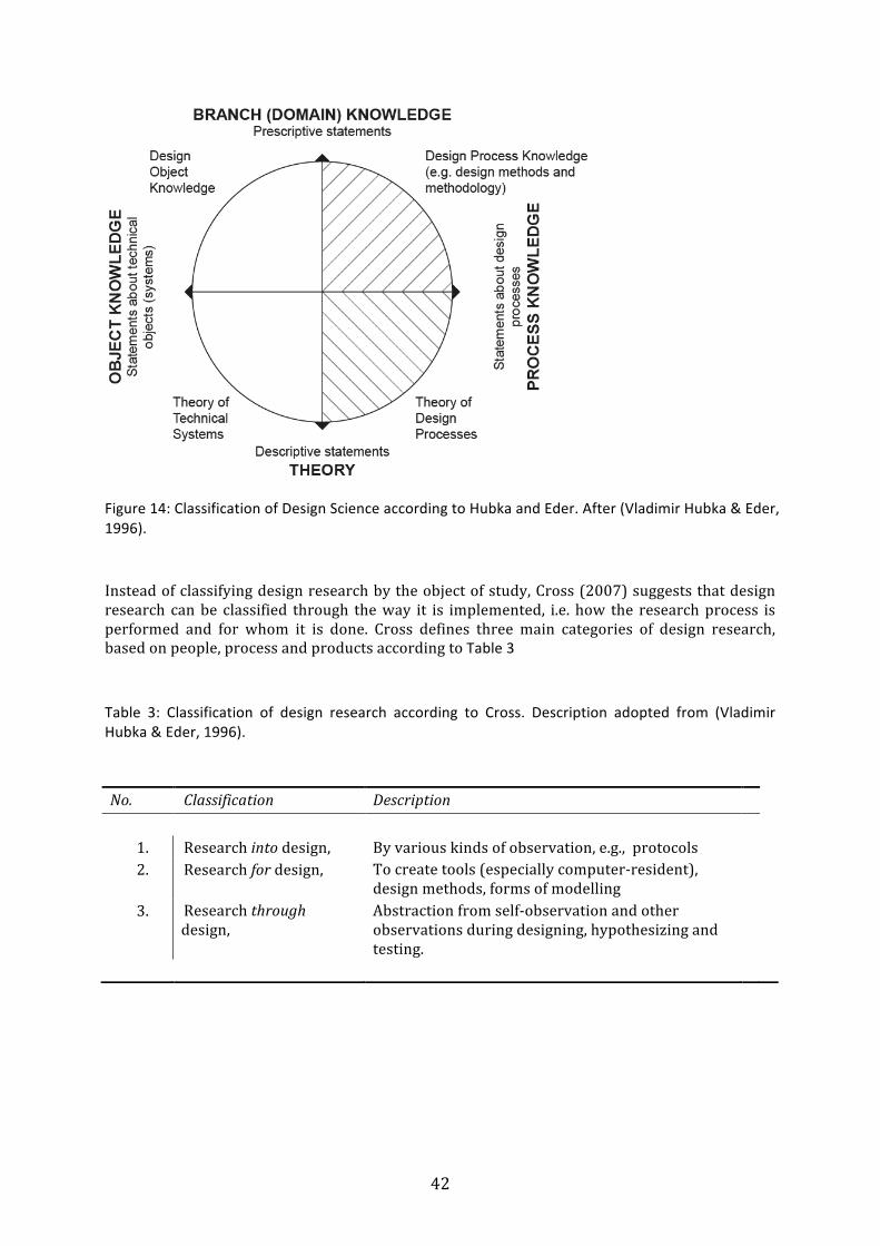
42
Figure 14: Classification of Design Science according to Hubka and Eder. After (Vladimir Hubka & Eder, 1996).
Instead of classifying design research by the object of study, Cross (2007) suggests that design research can be classified through the way it is implemented, i.e. how the research process is performed and for whom it is done. Cross defines three main categories of design research, based on people, process and products according to Table 3 Table 3: Classification of design research according to Cross. Description adopted from (Vladimir Hubka & Eder, 1996).
No. Classification Description
1. Research into design, By various kinds of observation, e.g., protocols 2. Research for design, To create tools (especially computer-‐resident),
design methods, forms of modelling
3. Research through design,
Abstraction from self-‐observation and other observations during designing, hypothesizing and testing.
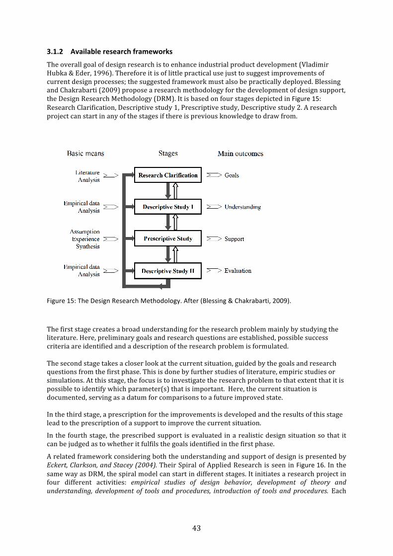
43
3.1.2 Available research frameworks
The overall goal of design research is to enhance industrial product development (Vladimir Hubka & Eder, 1996). Therefore it is of little practical use just to suggest improvements of current design processes; the suggested framework must also be practically deployed. Blessing and Chakrabarti (2009) propose a research methodology for the development of design support, the Design Research Methodology (DRM). It is based on four stages depicted in Figure 15: Research Clarification, Descriptive study 1, Prescriptive study, Descriptive study 2. A research project can start in any of the stages if there is previous knowledge to draw from.
Figure 15: The Design Research Methodology. After (Blessing & Chakrabarti, 2009).
The first stage creates a broad understanding for the research problem mainly by studying the literature. Here, preliminary goals and research questions are established, possible success criteria are identified and a description of the research problem is formulated. The second stage takes a closer look at the current situation, guided by the goals and research questions from the first phase. This is done by further studies of literature, empiric studies or simulations. At this stage, the focus is to investigate the research problem to that extent that it is possible to identify which parameter(s) that is important. Here, the current situation is documented, serving as a datum for comparisons to a future improved state. In the third stage, a prescription for the improvements is developed and the results of this stage lead to the prescription of a support to improve the current situation.
In the fourth stage, the prescribed support is evaluated in a realistic design situation so that it can be judged as to whether it fulfils the goals identified in the first phase.
A related framework considering both the understanding and support of design is presented by Eckert, Clarkson, and Stacey (2004). Their Spiral of Applied Research is seen in Figure 16. In the same way as DRM, the spiral model can start in different stages. It initiates a research project in four different activities: empirical studies of design behavior, development of theory and understanding, development of tools and procedures, introduction of tools and procedures. Each
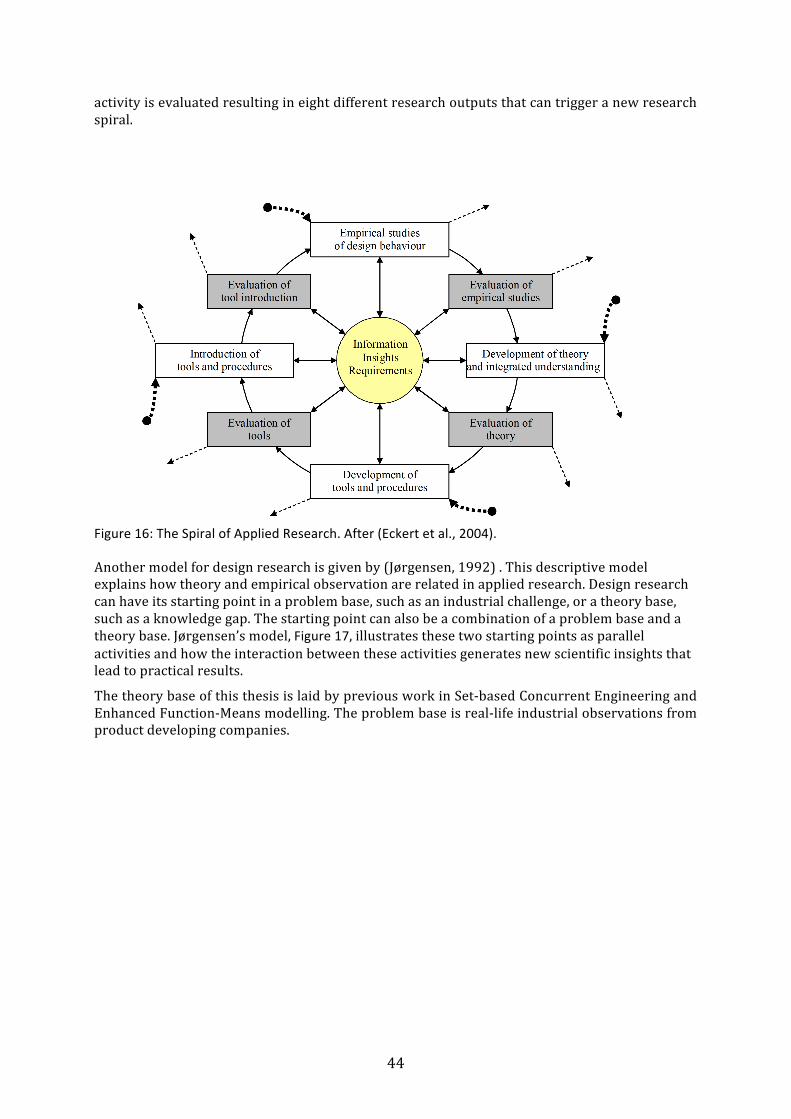
44
activity is evaluated resulting in eight different research outputs that can trigger a new research spiral.
Figure 16: The Spiral of Applied Research. After (Eckert et al., 2004).
Another model for design research is given by (Jørgensen, 1992) . This descriptive model explains how theory and empirical observation are related in applied research. Design research can have its starting point in a problem base, such as an industrial challenge, or a theory base, such as a knowledge gap. The starting point can also be a combination of a problem base and a theory base. Jørgensen’s model, Figure 17, illustrates these two starting points as parallel activities and how the interaction between these activities generates new scientific insights that lead to practical results.
The theory base of this thesis is laid by previous work in Set-‐based Concurrent Engineering and Enhanced Function-‐Means modelling. The problem base is real-‐life industrial observations from product developing companies.
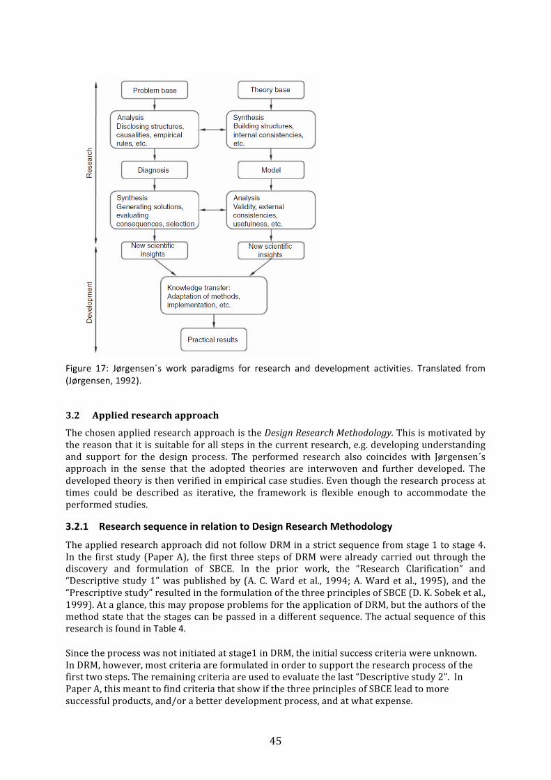
45
Figure 17: Jørgensen´s work paradigms for research and development activities. Translated from (Jørgensen, 1992).
3.2 Applied research approach
The chosen applied research approach is the Design Research Methodology. This is motivated by the reason that it is suitable for all steps in the current research, e.g. developing understanding and support for the design process. The performed research also coincides with Jørgensen´s approach in the sense that the adopted theories are interwoven and further developed. The developed theory is then verified in empirical case studies. Even though the research process at times could be described as iterative, the framework is flexible enough to accommodate the performed studies.
3.2.1 Research sequence in relation to Design Research Methodology
The applied research approach did not follow DRM in a strict sequence from stage 1 to stage 4. In the first study (Paper A), the first three steps of DRM were already carried out through the discovery and formulation of SBCE. In the prior work, the “Research Clarification” and “Descriptive study 1” was published by (A. C. Ward et al., 1994; A. Ward et al., 1995), and the “Prescriptive study” resulted in the formulation of the three principles of SBCE (D. K. Sobek et al., 1999). At a glance, this may propose problems for the application of DRM, but the authors of the method state that the stages can be passed in a different sequence. The actual sequence of this research is found in Table 4. Since the process was not initiated at stage1 in DRM, the initial success criteria were unknown. In DRM, however, most criteria are formulated in order to support the research process of the first two steps. The remaining criteria are used to evaluate the last “Descriptive study 2”. In Paper A, this meant to find criteria that show if the three principles of SBCE lead to more successful products, and/or a better development process, and at what expense.
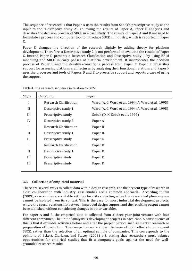
46
The sequence of research is that Paper A uses the results from Sobek’s prescriptive study as the input to the “Descriptive study 2”. Following the results of Paper A, Paper B analyses and describes the decision process of SBCE in a case study. The results of Paper A and B are used to formulate a process and computer tool to introduce SBCE in industry, which is reported in Paper C.
Paper D changes the direction of the research slightly by adding theory for platform development. Therefore, a Descriptive study 2 is not performed to evaluate the results of Paper C. Instead Paper D presents a Research Clarification and Descriptive study 1 by using EF-‐M modelling and SBCE in early phases of platform development. It incorporates the decision process of Paper B and the iterative/converging process from Paper C. Paper E prescribes support for assessing platform architectures by analysing their functional relations and Paper F uses the processes and tools of Papers D and E to prescribe support and reports a case of using the support.
Table 4: The research sequence in relation to DRM.
Stage Description Paper
I Research Clarification Ward (A. C. Ward et al., 1994; A. Ward et al., 1995)
II Descriptive study 1 Ward (A. C. Ward et al., 1994; A. Ward et al., 1995)
III Prescriptive study Sobek (D. K. Sobek et al., 1999)
IV Descriptive study 2 Paper A
I Research Clarification Paper B
II Descriptive study 1 Paper B
III
I
II
III
III
Prescriptive study
Research Clarification
Descriptive study 1
Prescriptive study
Prescriptive study
Paper C
Paper D
Paper D
Paper E
Paper F
3.3 Collection of empirical material
There are several ways to collect data within design research. For the present type of research in close collaboration with industry, case studies are a common approach. According to Yin (2009), case studies are suitable settings for data collecting when the researched phenomenon cannot be isolated from its context. This is the case for most industrial development projects, where the causal relationship between improved design support and the resulting output cannot be established without considering changes in other variables.
For paper A and B, the empirical data is collected from a three year joint-‐venture with four different companies. The unit of analysis is development projects in each case. A consequence of this is that it excludes activities before and after the project period, such as market research or preparation of production. The companies were chosen because of their efforts to implement SBCE, rather than the selection of an optimal sample of companies. This corresponds to the opinions of Eckert, Clarkson, and Stacey (2003) p.3, stating that researchers must balance opportunities for empirical studies that fit a company’s goals, against the need for well-‐grounded research results.
47
For Papers D and F, the research is performed within the Wingquist Laboratory Excellence Centre. For the last decade, the centre has been an arena for collaboration between industrial participants and the researchers within the centre. This long-‐term relationship creates continuity in research, opportunities for new research as well as a knowledge base to draw from. The knowledge base creates a head start for new projects by offering experienced colleagues, computer tools and related publications.
For all papers, the adopted view is that the participation of professional designers is essential in the research of industrial product development methods. With reference to Jørgensen (1992) , this industrial problem base cannot be replaced by students or by literature reviews.
The research of Paper A started with an exploratory study at the participating companies, in the form of pilot projects. Information was collected from semi-‐structured interviews with managers and design engineers, through studies of documents, and by a questionnaire at the end of the research project. The respondents were senior designers or managers with long experiences of product development. Other data sources were workshops at the companies where project members and researchers participated.
Following the analysis of the results, the study was extended to include an in-‐depth study of the SBCE decision process in one of the firms, on which paper B is based. Here, the main empiric material comes from following the design and decision process of two design engineers and one manager. Also, two cross-‐ functional workshops were held with representatives from mechanics-‐, electronics-‐ and production departments. Here, the researchers contributed by introducing tools and methods for Set-‐based decision making. Besides the notes recorded at the meetings, also extensive working material from the development process was collected.
Papers D and F partly build upon empirical data collected over several years within the Wingquist Laboratory. The collection of data for the turbine rear structure is reported by and Michaelis (2013) and Levandowski (2014). Additional data for extending the turbine rear structure model in Papers D and F was collected in collaboration with the participating company, through meetings and workshops.
Additional data in Paper F was collected through four international reviews with engineers within the European aerospace industry. Here, the platform models built in the demonstrator software were used as a mediating object to enable feedback on the results from the companies. Apart from the reviews, several workshops and digital meetings were held in order to obtain the information to populate the demonstrator models. The meetings all followed an agenda, and the data acquisition method can be described as semi –structured.
3.4 Validating and verifying the quality of the results
Quality assessment is a crucial component of the research process, often using the terms validation and verification. Unfortunately, these terms are used differently within different research disciplines. Within this research, verification and validation are seen as separate constructs that are used together for assessing the relevance and authenticity of the performed research. Verification seeks to answer the question “Have we done things in the right way?” and validation seeks to answer the question “Have we done the right things?”.
The reliability of the results in this work is verified by assessing the research approach and methodological rigour. The validity of the research results in this work is regarded as a matter of how relevant and applicable the results are in order to handle the addressed problems in their intended contexts. For the purpose of validation, application, assessment and acceptance of the results by professional users in such contexts are useful (Buur, 1990; Eckert et al., 2004). Both approaches for assessing the quality of the results are therefore used in this thesis.
48
3.4.1 Criteria for valid design research according to Cross
Cross draws a distinct line between ordinary day-‐to day development work and that of research and states that
“I do not see how “normal works of practice can be regarded as works of research. The whole point of doing research is to extract reliable knowledge…. ..and to make that knowledge available to others in re-‐usable form.” (Cross, 2007).
Cross further presents a list of criteria for valid design research, that should have the following characteristics (Cross, 2007):
-‐ Purposive – based on identification of an issue or problem worthy and capable of investigation
-‐ Inquisitive – seeking to acquire new knowledge
-‐ Informed – conducted from an awareness of previous, related research
-‐ Methodical – planned and carried out in an efficient and disciplined manner
-‐ Communicable – generating and reporting results which are testable and accessible by others.
The first two aspects and the fourth aspect are addressed in this chapter. The third aspect is addressed in Chapter 2 and the fifth aspect is reported in Chapter 4.
3.4.2 Criteria for valid design research according to Buur
The following list of criteria was proposed by Buur (Buur, 1990) for verifying the validity of design theories. Buur states that design research cannot be validated through scientific methods such as controlled experiments. The reason for this is that the number of control factors are large, making it unfeasible to repeat the experiments. Also, design processes are unpredictable in the way that a specific outcome cannot be accredited to the applied design method. For these reasons, Buur introduces a list of criteria for the validity of design research: Logical verification
-‐ Consistency: no internal conflicts between individual elements (e.g. axioms) of the theory.
-‐ Completeness: all relevant phenomena observed previously can be explained or rejected by theory (i.e. observation, from literature, industrial experience, etc.)
-‐ Well established and successful methods are in agreement with theory. -‐ Cases (i.e. particular design projects) and specific design problems can be explained by
means of the theory. Verification by acceptance
-‐ Statements of the theory (axioms, theorems) are acceptable to experienced designers. -‐ Models and methods derived from the theory are acceptable to experienced designers.
Verification by acceptance is also suggested by Eckert et al. ((Eckert et al., 2004), p. 6) note: “The most useful criterion for success is the perception of value in new procedures and methods by design practitioners in industry.” In chapter 5, the validity of the research is discussed based on the criteria of Cross and Buur.
49
4 Results This chapter presents an overview of the results gained throughout the studies presented in the appended papers. The focus is set on clarifying how each paper contributes to answering the research questions. Research Question 1 is essentially aimed at developing understanding of the characteristics of SBCE in industrial product development, while Research Question 2 focuses on clarifying how SBCE can be used to manage constraints and enable convergence of solutions for products and product platforms. Research Question 3 aims at developing support to enable SBCE in the earliest phases of product platform development, specifically for the phases foregoing embodiment design.
4.1 Paper A: Exploring Set-‐Based Concurrent Engineering. Paper A presents an explorative study to develop understanding of different aspects of SBCE. It does so by introducing the three principles of SBCE in pilot projects at four companies. The paper presents the set-‐up and findings, which are a compilation of results, experiences and challenges identified in the implementation of SBCE. The study was part of a three year joint-‐venture between industry, the School of Engineering in Jönköping and the research institute Swerea IVF. The framework for research was based on six pilot cases in four companies. These represent a wide selection of industries, working in the businesses of electronic systems, graphic industry, automotive components and heavy trucks. The size of the companies is also a wide range, having between 100 and 30 000+ employees. For each participating company, the studied design process was adapted to the principles of SBCE and the teams were allowed to bypass the ordinary development processes whenever appropriate for the project. To create a broad acceptance for the methodology, a core team of managers and engineers from across the organization was given an introduction to SBCE. An active research strategy was used with workshops at the participating companies, studying the development costs and use of resources, the characteristics of the resulting products and development process metrics. Information was collected in workshops and interviews with senior designers or managers with long experiences of product development and from a questionnaire. The information was used to compare SBCE to the standard development practice of the companies. On each parameter, the results were given 1 point if SBCE created a better result than current development practice, 0 points if the output was equally good and -‐1 point for an inferior output. The individual values for each company were plotted in diagrams together with the average score for all companies.
4.1.1 What are the effects of SBCE? The effects on project lead time, development costs and product cost are displayed in Figure 18. The pilot projects had slightly longer lead times than comparable projects. There could be many reasons for this, but one reason mentioned by the engineers is that they are not used to this way of working. An extensive documentation also took more time than usual. In all projects extra resources were allocated to enable thorough exploration of parallel solutions in early phases of development. This caused the pilots to have slightly higher average development costs compared to standard projects. One manager commented that the budget increase was surprisingly small compared to the increased product knowledge generated. In all but one project, the product costs were reduced. One of the companies reported a 40% decrease in product cost compared to the initial calculated cost. This was achieved by having high-‐risk product architecture with inexpensive components in parallel to safer alternatives. The thorough evaluation of multiple combinations proved that the low-‐cost solution was good enough.
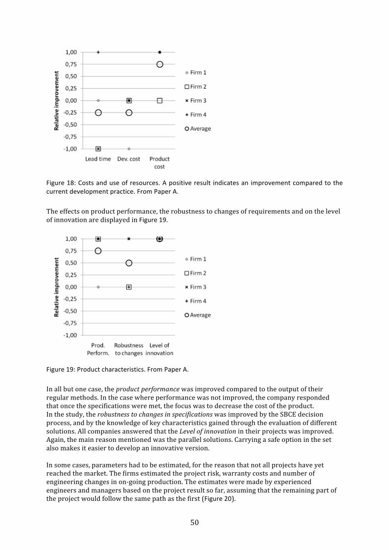
50
Figure 18: Costs and use of resources. A positive result indicates an improvement compared to the current development practice. From Paper A.
The effects on product performance, the robustness to changes of requirements and on the level of innovation are displayed in Figure 19.
Figure 19: Product characteristics. From Paper A.
In all but one case, the product performance was improved compared to the output of their regular methods. In the case where performance was not improved, the company responded that once the specifications were met, the focus was to decrease the cost of the product. In the study, the robustness to changes in specifications was improved by the SBCE decision process, and by the knowledge of key characteristics gained through the evaluation of different solutions. All companies answered that the Level of innovation in their projects was improved. Again, the main reason mentioned was the parallel solutions. Carrying a safe option in the set also makes it easier to develop an innovative version. In some cases, parameters had to be estimated, for the reason that not all projects have yet reached the market. The firms estimated the project risk, warranty costs and number of engineering changes in on-‐going production. The estimates were made by experienced engineers and managers based on the project result so far, assuming that the remaining part of the project would follow the same path as the first (Figure 20).
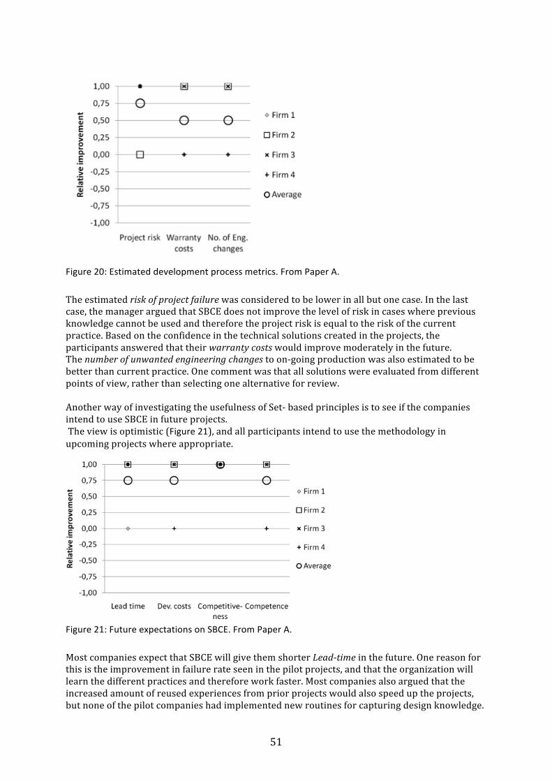
51
Figure 20: Estimated development process metrics. From Paper A.
The estimated risk of project failure was considered to be lower in all but one case. In the last case, the manager argued that SBCE does not improve the level of risk in cases where previous knowledge cannot be used and therefore the project risk is equal to the risk of the current practice. Based on the confidence in the technical solutions created in the projects, the participants answered that their warranty costs would improve moderately in the future. The number of unwanted engineering changes to on-‐going production was also estimated to be better than current practice. One comment was that all solutions were evaluated from different points of view, rather than selecting one alternative for review. Another way of investigating the usefulness of Set-‐ based principles is to see if the companies intend to use SBCE in future projects. The view is optimistic (Figure 21), and all participants intend to use the methodology in upcoming projects where appropriate.
Figure 21: Future expectations on SBCE. From Paper A.
Most companies expect that SBCE will give them shorter Lead-‐time in the future. One reason for this is the improvement in failure rate seen in the pilot projects, and that the organization will learn the different practices and therefore work faster. Most companies also argued that the increased amount of reused experiences from prior projects would also speed up the projects, but none of the pilot companies had implemented new routines for capturing design knowledge.
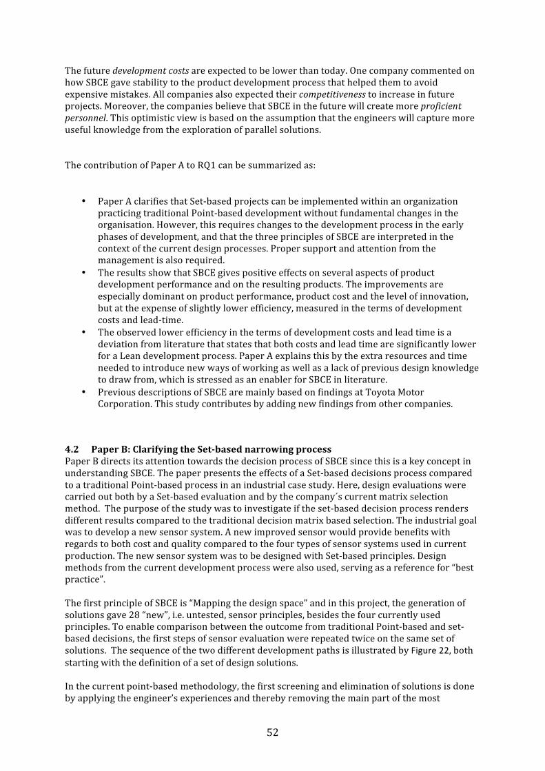
52
The future development costs are expected to be lower than today. One company commented on how SBCE gave stability to the product development process that helped them to avoid expensive mistakes. All companies also expected their competitiveness to increase in future projects. Moreover, the companies believe that SBCE in the future will create more proficient personnel. This optimistic view is based on the assumption that the engineers will capture more useful knowledge from the exploration of parallel solutions. The contribution of Paper A to RQ1 can be summarized as:
• Paper A clarifies that Set-‐based projects can be implemented within an organization
practicing traditional Point-‐based development without fundamental changes in the organisation. However, this requires changes to the development process in the early phases of development, and that the three principles of SBCE are interpreted in the context of the current design processes. Proper support and attention from the management is also required.
• The results show that SBCE gives positive effects on several aspects of product development performance and on the resulting products. The improvements are especially dominant on product performance, product cost and the level of innovation, but at the expense of slightly lower efficiency, measured in the terms of development costs and lead-‐time.
• The observed lower efficiency in the terms of development costs and lead time is a deviation from literature that states that both costs and lead time are significantly lower for a Lean development process. Paper A explains this by the extra resources and time needed to introduce new ways of working as well as a lack of previous design knowledge to draw from, which is stressed as an enabler for SBCE in literature.
• Previous descriptions of SBCE are mainly based on findings at Toyota Motor Corporation. This study contributes by adding new findings from other companies.
4.2 Paper B: Clarifying the Set-‐based narrowing process Paper B directs its attention towards the decision process of SBCE since this is a key concept in understanding SBCE. The paper presents the effects of a Set-‐based decisions process compared to a traditional Point-‐based process in an industrial case study. Here, design evaluations were carried out both by a Set-‐based evaluation and by the company´s current matrix selection method. The purpose of the study was to investigate if the set-‐based decision process renders different results compared to the traditional decision matrix based selection. The industrial goal was to develop a new sensor system. A new improved sensor would provide benefits with regards to both cost and quality compared to the four types of sensor systems used in current production. The new sensor system was to be designed with Set-‐based principles. Design methods from the current development process were also used, serving as a reference for “best practice”. The first principle of SBCE is “Mapping the design space” and in this project, the generation of solutions gave 28 “new”, i.e. untested, sensor principles, besides the four currently used principles. To enable comparison between the outcome from traditional Point-‐based and set-‐based decisions, the first steps of sensor evaluation were repeated twice on the same set of solutions. The sequence of the two different development paths is illustrated by Figure 22, both starting with the definition of a set of design solutions. In the current point-‐based methodology, the first screening and elimination of solutions is done by applying the engineer’s experiences and thereby removing the main part of the most

53
spectacular solutions, followed by a decision matrix based selection of the best or a few best solutions for further development.
Figure 22: The current Point-‐based process and the Set-‐based process. From Paper B.
4.2.1 Traditional decision process The first round of evaluations was a screening of the immature concepts, a subjective intuitive process where the designers estimated both the technical potential and the risk of failure for each alternative on a ten grade scale. The alternatives having their potential risk greater than their potential success were eliminated and the result was that most unfamiliar solutions were stopped in this phase. Also three solutions were eliminated since they did not fall into the scope of the project. The result was an elimination of 20 solutions. The second round evaluation of the remaining alternatives was made by both Pugh’s and Kesselring’s matrix evaluations. Kesselring’s evaluation was simplified in the sense that the scale for how the individual design solutions were rated had three steps rather than the usual five steps. The intention of Pugh’s method is a repeated selection-‐development, but in the current set-‐up, only one round of evaluation was planned before restart and initiation of the set-‐based elimination. A careful selection of the datum is also important, and the optical gate sensor was selected for this purpose. Also the effect of weight factors on the evaluation was investigated by comparing the results generated by the Kesselring and Pugh matrixes. Table 5 shows the result of both Pugh and Kesselring evaluations after applying the firm’s 24 criteria for evaluation. Note that there is an agreement between the selection methods on which technologies are the most promising (marked in grey).
Table 5: Results from the second round of evaluation. The most promising technologies are marked in grey; the current technology is marked by bold text. Adapted from Paper B.
Concept Pugh score: Kesselring score: Optical gate 0 0 Hall sensor -‐1 -‐40 Reed sensor 0 -‐37 Mechanical switch -‐1 -‐39 Capacitive sensor 0 25 Inductive sensor -‐1 2 Back bias -‐3 -‐25 Solenoid Permeability 3 33 Solenoid inductivity 6 62 Short circuit 1 -‐3
Brainstorming/ Mapping of Design
space Gut-‐feel
elimination Pugh/
Kesselring selection
Development of a few best alternatives
Repeat: Selection-‐
Development
Brainstorming/ Mapping of Design space
Elimination by intersection/ unfeasibility
Development of
remaining alternatives
Elimination by tightening of specifcations
Repeat: Elimination-‐ Development

54
Plunger as potentiometer
-‐1 -‐8
Multiple coils 5 85 Even though there were uncertainties in the evaluation, none of the currently used solutions (bold text) received a high score. The conclusion from this example was that the traditional Point-‐based methods seem to favour new, unknown solutions over established solutions where the shortcomings are known. The selection process was halted here but the next step would be selecting a best alternative for preliminary design, likely one of the alternatives having the best score.
4.2.2 Set-‐based decision process After completing the traditional decision matrixes the evaluation process started over again with the initial 32 solutions. The elimination was done according to SBCE principle 2 and 3 starting with readily available information. Initially, simple criteria such as “technology readiness” was used, where the availability of commercial “off the shelf” components were enough to keep the solution in the set. If data was unknown, a question mark was noted, indicating that more work was needed. Solutions that were out of the project scope were also eliminated as well as solutions that were incompatible with adjacent systems or could not fulfil the functions needed. Further elimination was done stepwise by acquiring knowledge of the solutions, as opposed to the intuitive standard decision process used in the company. The first criteria concerned sensor functions and could often be found in data sheets. Properties such as detection distance and precision were clarified and any component fulfilling the initial broad specifications was kept in the set. Subsequent elimination was done by adding more constraints such as the need for special voltages, external processor requirements or detector size. After some time there were 14 remaining solutions but no more data could be found by desk-‐top studies. Table 6 describes the status of the elimination process at this point. Note that highest ranked alternatives from the matrix evaluations are not superior to the other remaining solutions. Table 6: Results from the Set-‐based evaluation. The current technology is marked in bold text and the top 3 solutions from the Point-‐based evaluations are marked in italics. A question mark indicates that more information is needed to make a decision and grey areas represent eliminated solutions. Adapted from Paper B.
Concept Eliminated by availability, compatibility
Eliminated by preliminary performance
Eliminated by more constraints
Activation current ? ? Angular sensor x Back bias ? ? Cam curve x Capacitive sensor ? x Conductive carbon x Conductive fluid x Current and voltage through solenoid
? ?
External permeability ? ?
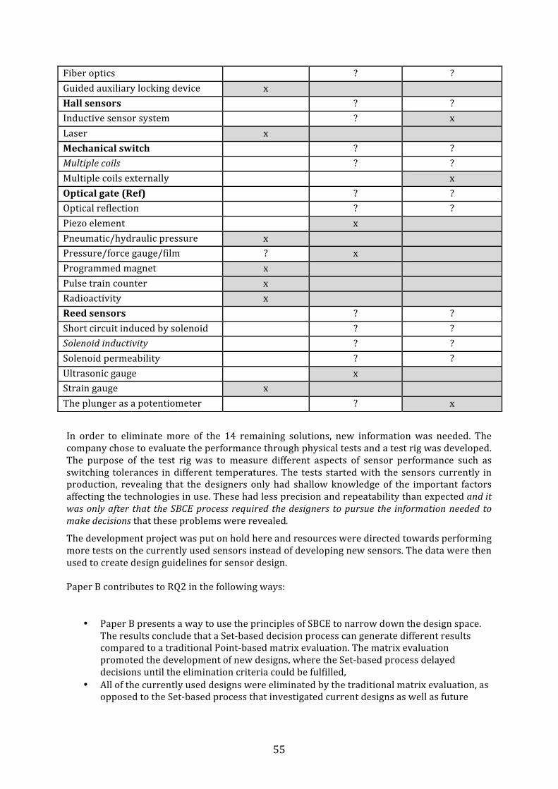
55
In order to eliminate more of the 14 remaining solutions, new information was needed. The company chose to evaluate the performance through physical tests and a test rig was developed. The purpose of the test rig was to measure different aspects of sensor performance such as switching tolerances in different temperatures. The tests started with the sensors currently in production, revealing that the designers only had shallow knowledge of the important factors affecting the technologies in use. These had less precision and repeatability than expected and it was only after that the SBCE process required the designers to pursue the information needed to make decisions that these problems were revealed.
The development project was put on hold here and resources were directed towards performing more tests on the currently used sensors instead of developing new sensors. The data were then used to create design guidelines for sensor design. Paper B contributes to RQ2 in the following ways:
• Paper B presents a way to use the principles of SBCE to narrow down the design space. The results conclude that a Set-‐based decision process can generate different results compared to a traditional Point-‐based matrix evaluation. The matrix evaluation promoted the development of new designs, where the Set-‐based process delayed decisions until the elimination criteria could be fulfilled,
• All of the currently used designs were eliminated by the traditional matrix evaluation, as opposed to the Set-‐based process that investigated current designs as well as future
Fiber optics ? ? Guided auxiliary locking device x Hall sensors ? ? Inductive sensor system ? x Laser x Mechanical switch ? ? Multiple coils ? ? Multiple coils externally x Optical gate (Ref) ? ? Optical reflection ? ? Piezo element x Pneumatic/hydraulic pressure x Pressure/force gauge/film ? x Programmed magnet x Pulse train counter x Radioactivity x Reed sensors ? ? Short circuit induced by solenoid ? ? Solenoid inductivity ? ? Solenoid permeability ? ? Ultrasonic gauge x Strain gauge x The plunger as a potentiometer ? x

56
alternatives in the same way. It thereby revealed the lack of knowledge of the important design parameters in current designs being the root cause of the existing problems.
• The efficiency of the Set-‐based decision process was demonstrated when the industrial partner preferred the results from the Set-‐based evaluations instead of the results from traditional Point-‐based matrix evaluations. It is however, impossible to draw general conclusions from one case study and a superior decision methodology cannot be identified. The study is valid for the case it represents, where it concludes that these two approaches generate disparate results.
4.3 Paper C: A process and tool to introduce Set-‐Based Concurrent Engineering Paper C presents a structured process and computer tool for the introduction of SBCE in companies having a traditional Point-‐based development environment. The usefulness of the proposed process is demonstrated by applying information from an industrial concept development project, showing how the proposed process could implement the three principles of SBCE in a traditional Point-‐based development environment. Since a Set-‐based process is described as difficult to implement, the objective of the work is to develop a structured process supported by the three principles of SBCE. The first principle, “map the design space”, starts with the definition of feasible regions. These regions are built up by designing multiple alternatives. Here, no new approaches are needed and there are sufficient creative methods and systematic approaches available. A well-‐known tool that can be adapted to fulfil the first principle is the morphological chart. In Paper C, two novelties are introduced to create the Extended morphological chart depicted in Figure 23:
• Each set is identified with a row in the morphological chart, and the sets are thereby becoming concrete, tangible objects.
• The chart is extended by the introduction of elements from other domains that are not related to design solutions. A traditional morphological chart only contains solutions to product functions, but in the proposed process, also the possible business cases, manufacturing processes, styling or other important aspects can be included.
Figure 23: The mapping of functions from different domains in the Extended morphological chart. From Paper C.
To create the mapping of the design space, common creative methods are used to generate ideas. Figure 23 illustrates how each function and its solutions are denoted in rows, representing the different sets. The Extended morphological chart provides a visual overview of the possible combinations, thereby communicating the sets of possibilities. In order to explore trade-‐offs by designing multiple alternatives, the chart should be flexible and expanded with different solutions as the process proceeds. The second principle, “Integrate by intersection”, identifies intersections between the different sets by two different approaches. The first is to find the region where members of the individual
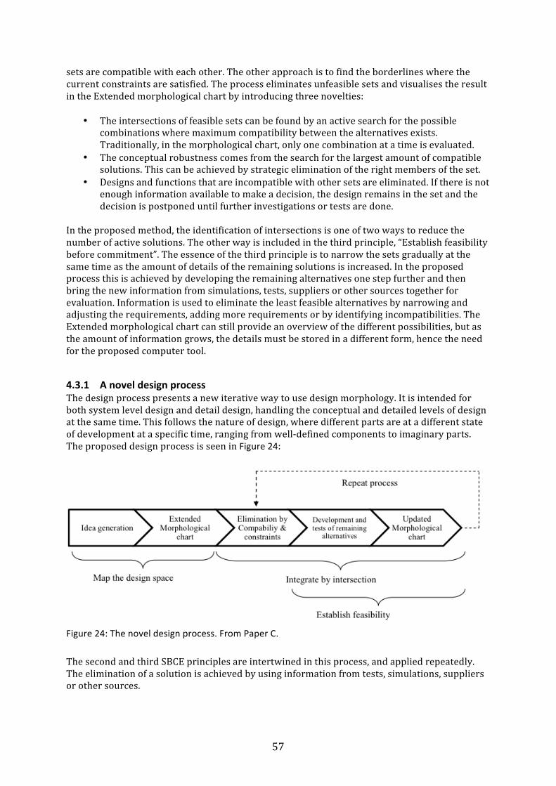
57
sets are compatible with each other. The other approach is to find the borderlines where the current constraints are satisfied. The process eliminates unfeasible sets and visualises the result in the Extended morphological chart by introducing three novelties:
• The intersections of feasible sets can be found by an active search for the possible combinations where maximum compatibility between the alternatives exists. Traditionally, in the morphological chart, only one combination at a time is evaluated.
• The conceptual robustness comes from the search for the largest amount of compatible solutions. This can be achieved by strategic elimination of the right members of the set.
• Designs and functions that are incompatible with other sets are eliminated. If there is not enough information available to make a decision, the design remains in the set and the decision is postponed until further investigations or tests are done.
In the proposed method, the identification of intersections is one of two ways to reduce the number of active solutions. The other way is included in the third principle, “Establish feasibility before commitment”. The essence of the third principle is to narrow the sets gradually at the same time as the amount of details of the remaining solutions is increased. In the proposed process this is achieved by developing the remaining alternatives one step further and then bring the new information from simulations, tests, suppliers or other sources together for evaluation. Information is used to eliminate the least feasible alternatives by narrowing and adjusting the requirements, adding more requirements or by identifying incompatibilities. The Extended morphological chart can still provide an overview of the different possibilities, but as the amount of information grows, the details must be stored in a different form, hence the need for the proposed computer tool.
4.3.1 A novel design process The design process presents a new iterative way to use design morphology. It is intended for both system level design and detail design, handling the conceptual and detailed levels of design at the same time. This follows the nature of design, where different parts are at a different state of development at a specific time, ranging from well-‐defined components to imaginary parts. The proposed design process is seen in Figure 24:
Figure 24: The novel design process. From Paper C.
The second and third SBCE principles are intertwined in this process, and applied repeatedly. The elimination of a solution is achieved by using information from tests, simulations, suppliers or other sources.
58
4.3.2 A supporting computer tool The Extended morphological chart is implemented in a spread sheet template. A spread-‐sheet concept was selected because of the ease of use and the speed of creating a prototype system. Also, necessary calculations can be done in the spread-‐sheet. The main function is to display information on different solutions, to link values and keep track of the requirement space. The tool is based on four templates:
• The “Morphological overview” is the master sheet, linking to additional information pages that provide deeper details of the specific solutions.
• The “Specification manager” that keeps track of the evolving specifications and the converging constraints.
• The “Technology manager” containing relevant information of the solutions/components.
• The “Morphological relations” template that stores the reasons for decisions. The supporting tool is demonstrated by a case study using information collected from a completed point-‐based development project that is chosen because of the appropriate complexity allowing the different features of the computer tool to be evaluated. The product is a battery powered consumer product manufactured in large volumes having two basic functions: To clean and polish surfaces. This requires different tools and different peripheral speed. The initial design space may look as in Table 7. Table 7: Initial design space. From Paper C.
Set Solution Enable use 8 different industrial designs Create power Brushed DC Stepper motor Control power PWM Step-‐control Store energy AA cells AAA cells Prismatic cells Control Speed Encoder measurement Current
measurement Step-‐counting
Enable movement Reciprocal mechanism Programmed Detect tool Magnetic Optic Switch The feasible regions of the design space are described by different sets: Styling, electronics, mechanics etc. Worth noting is that in Table 7 the sets “speed control” and “movement” are realised in different ways: as separate solutions using a motor, controller, encoder and mechanism, or integrated as in the step motor drive. This indicates that the process supports different types of representation, from a strict functional decomposition to integrated function carriers and “organs” (Vladimir Hubka & Eder, 1992), fulfilling multiple functions. The second and third principles are intertwined and the process now repeats principle 2 and 3 until only one solution remains. This follows the nature of design, where different parts can simultaneously be at a different state of development. In the present example, this is demonstrated by the speed control and tool detection both being conceptual solutions, while other systems have already gone through substantial development. To find the intersections the first step is to increase the detail of different sets. All components created under Principle 1 are listed in their own row of a template and assigned to different sub-‐sets. The set number 5 has the subsets 51, 52 and 53, and new subsets can be added by inserting a new column in the chart, see Figure 25.

59
A component can also be a member of many sets, an organ, fulfilling multiple functions. This is demonstrated by the component “Step-‐controller 1”, being a member of the sets “Controller”, “Speed control” and “Movement”. This is displayed by a green mark in the corresponding column. It also has a yellow exclamation mark in column 4 “Battery” that indicates that it requires this set to work. The dependencies between sets and components are described only in one direction, exemplified by the motor requiring a controller, and the controller requiring a battery and a speed measurement. The reason for this is to make the description clear and avoid circular dependencies.
Figure 25: Morphological relations. From Paper C.
Preferably, the process starts with “low hanging fruits”-‐ readily available information that is easy to obtain. This rapidly decreases the number of remaining alternatives. If set 32 “Step-‐control” (Figure 25) is found unfeasible, all four stepper motors are also eliminated. The relative compatibility of each set compared to other sets is investigated on other pages of the Morphological relations template. This compares every component to all components of the other sets of solutions. In the case of reducing the number of possible battery configurations, Figure 26, the batteries that cannot provide the correct voltage and storage capacity for a specific motor are marked, leading to the elimination of some components, indicated by a red X.
!

60
Figure 26: Component compatibility. From Paper C.
Figure 8 indicates that there is a watershed between two distinct conceptual solutions: The DC-‐motor and the stepper motor are not compatible. In the proposed process, no premature choice of a best concept is made. The goal is to explore the concepts step-‐by-‐step to the point that it is possible to eliminate confidently one or a few inferior designs from the set of active solutions, not to gain a complete knowledge of the design space. In this example, more information is needed to eliminate one of the motor technologies, and information can be found by further investigation of compatibility. When all incompatibility issues are resolved, applying more constraints allows subsequent elimination. These are stored in the “Specification manager” template. From specific requirements in the template, values can be linked to individual components if needed. The most important information on each component is put in a template of the “Technology manager”, Figure 27.
Figure 27: The Technology Manager template holds important technical information. From Paper C.
Here, attributes and relations to other sets are displayed, and important specifications are linked. Whenever possible, each requirement is an interval instead of a fixed number. By applying constraints, more solutions that fall outside the allowed range are eliminated. Basic calculations can be done in the templates of each component, and aggregate calculations, such as weight and cost, are done in the Specification manager (Figure 28) in the form of intervals.
!
!

61
Figure 28: The Specification Manager template. From Paper C.
The process now proceeds with a repeated increase of details and elimination. When a set or component is eliminated, it is marked in the Morphological overview. At the same time, more details are created that need to be added. An example of how the process could work is the development of the mechanism. Depending on the styling, the space available is distributed differently, and only some mechanisms and motors will fit a specific design. In the project, an evolving sequence of similar designs was developed, with the goal to arrive at a good compromise between the most favourable styling, motor, batteries and mechanism. The team arrived at a solution having high vibration levels. After a redesign to reduce vibrations, the team started over with another mechanism concept. In the proposed approach, instead of starting a re-‐design, the other mechanism concepts should be developed to a level where it is possible to compare it to the failing mechanism. Also information from these failed designs could be used to evaluate the compatibility between specific motors, designs and batteries and thereby reduce the amount of remaining solutions. At this stage of development, the Morphological overview could look like Figure 29, where the eliminated members are marked by red graphics.
Figure 29: The Morphological overview. Red graphics indicates eliminated solutions. From Paper C.
The paper introduces a way to support development by introducing the principles of SBCE and controlling the convergence of the design process. The contribution of Paper C to RQ1 and RQ2 can be summarized as:
!
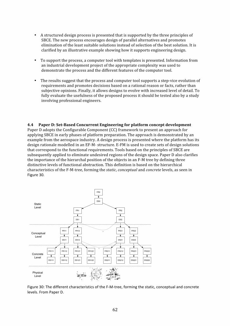
62
• A structured design process is presented that is supported by the three principles of
SBCE. The new process encourages design of parallel alternatives and promotes elimination of the least suitable solutions instead of selection of the best solution. It is clarified by an illustrative example showing how it supports engineering design.
• To support the process, a computer tool with templates is presented. Information from an industrial development project of the appropriate complexity was used to demonstrate the process and the different features of the computer tool.
• The results suggest that the process and computer tool supports a step-‐vice evolution of
requirements and promotes decisions based on a rational reason or facts, rather than subjective opinions. Finally, it allows designs to evolve with increased level of detail. To fully evaluate the usefulness of the proposed process it should be tested also by a study involving professional engineers.
4.4 Paper D: Set-‐Based Concurrent Engineering for platform concept development Paper D adopts the Configurable Component (CC) framework to present an approach for applying SBCE in early phases of platform preparation. The approach is demonstrated by an example from the aerospace industry. A design process is presented where the platform has its design rationale modelled in an EF-‐M-‐ structure. E-‐FM is used to create sets of design solutions that correspond to the functional requirements. Tools based on the principles of SBCE are subsequently applied to eliminate undesired regions of the design space. Paper D also clarifies the importance of the hierarchal position of the objects in an F-‐M tree by defining three distinctive levels of functional abstraction. This definition is based on the hierarchical characteristics of the F-‐M-‐tree, forming the static, conceptual and concrete levels, as seen in Figure 30.
Figure 30: The different characteristics of the F-‐M-‐tree, forming the static, conceptual and concrete levels. From Paper D.
FR0
DS0
FR1
DS1
FR2
DS2
FR21
DS21
FR22
DS22
FR11
DS11
FR12
DS12
FR121
DS121
FR122
DS122
FR111
DS111
FR112
DS112
FR221
DS221
FR222
DS222
FR211
DS211
FR212
DS212
Static Level
Conceptual Level
ConcreteLevel
PhysicalLevel
iw
iw

63
At the static level, there is little variation in alternative sets of solutions. The static level is defined by functions that contain the core of the system or platform, and thus rarely change between product generations. The conceptual level allows the complete range of possible solutions. It holds multiple branches of FRs and DSs to higher level requirements that represent various concepts. The concrete level contains the functional features (DSs) that define the physical embodiment. There is a clear distinction between the physical architecture and the functional architecture, implying that there is no 1:1 mapping between these. Multiple functional features from different functional branches can be integrated into a physical design but also the opposite, where a functional feature is distributed over several components. The physical level in Figure 30 is not included in the F-‐M tree but is the result of the subsequent engineering design process. The presented design process has four major activities, three that are iterated for each level in the F-‐M tree:
• Generate and structure solutions • Specify solutions • Narrowing of sets
The last step, compilation of bandwidth, is done when the FM-‐tree is ready. Initially, the functional architecture is structured according to the EF-‐M methodology. For each level in the architecture, the solutions are collected and generated to build up the design space by modelling the sets of possible solutions to functional requirement creating separate sub-‐ branches. Following the generation of functional requirements and design solutions, each solution needs to be specified to a sufficient degree that enables elimination of undesired solutions. In terms of functional modelling, this refers to elaborating the relations in the EF-‐M-‐model in the form of interacts-‐with and is-‐influenced-‐by relations. These relationships can be binary in the sense that they indicate that a significant connection exists, but also more specific in the form of trade-‐off curves that describe how the entities affect each other. Lastly, the sets of possible solutions are narrowed down and in this phase the goal is to reduce the number of candidate architectures that could fulfil the overall functional requirements. In this context, following the principles of SBCE, the architecture of an emergent system is evaluated before it is elaborated fully. This is important in order to reduce the amount of development work. In theory, numerous platform concepts could be generated by combining all design solutions on all levels, resulting in a comprehensive design space that is difficult to manage. The iterative nature of the SBCE development and decision process helps resolve this issue by gradually increasing the level of detail, while narrowing down solutions. The three activities generate, specify and eliminate are repeated in cycles at each level of abstraction as the granularity increases, again following the principles of SBCE.
4.4.1 Functional modelling of interactions The approach presents several ways of narrowing down a set and elimination is based on a number of different criteria. The initial strategy is an assessment of the compatibility between Design Solutions. This compatibility can be modelled using the interacts_with relationship that play a major role in defining concepts, and thus can eliminate a great number of unfeasible designs. Eliminating a design solution at the Conceptual level effectively prunes a branch of underlying FR and DSs which can be seen in Figure 32.
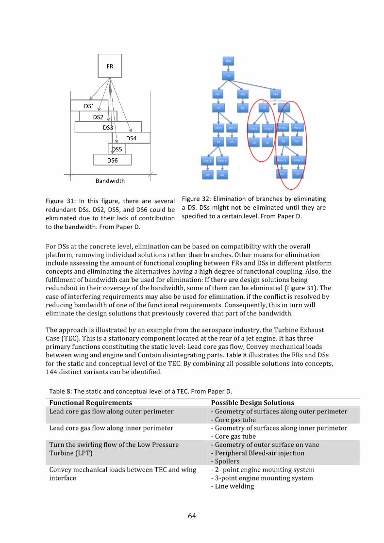
64
Figure 31: In this figure, there are several redundant DSs. DS2, DS5, and DS6 could be eliminated due to their lack of contribution to the bandwidth. From Paper D.
Figure 32: Elimination of branches by eliminating a DS. DSs might not be eliminated until they are specified to a certain level. From Paper D.
For DSs at the concrete level, elimination can be based on compatibility with the overall platform, removing individual solutions rather than branches. Other means for elimination include assessing the amount of functional coupling between FRs and DSs in different platform concepts and eliminating the alternatives having a high degree of functional coupling. Also, the fulfilment of bandwidth can be used for elimination: If there are design solutions being redundant in their coverage of the bandwidth, some of them can be eliminated (Figure 31). The case of interfering requirements may also be used for elimination, if the conflict is resolved by reducing bandwidth of one of the functional requirements. Consequently, this in turn will eliminate the design solutions that previously covered that part of the bandwidth. The approach is illustrated by an example from the aerospace industry, the Turbine Exhaust Case (TEC). This is a stationary component located at the rear of a jet engine. It has three primary functions constituting the static level: Lead core gas flow, Convey mechanical loads between wing and engine and Contain disintegrating parts. Table 8 illustrates the FRs and DSs for the static and conceptual level of the TEC. By combining all possible solutions into concepts, 144 distinct variants can be identified. Table 8: The static and conceptual level of a TEC. From Paper D.
Functional Requirements Possible Design Solutions Lead core gas flow along outer perimeter -‐ Geometry of surfaces along outer perimeter
-‐ Core gas tube Lead core gas flow along inner perimeter -‐ Geometry of surfaces along inner perimeter
-‐ Core gas tube Turn the swirling flow of the Low Pressure Turbine (LPT)
-‐ Geometry of outer surface on vane -‐ Peripheral Bleed-‐air injection -‐ Spoilers
Convey mechanical loads between TEC and wing interface
-‐ 2-‐ point engine mounting system -‐ 3-‐point engine mounting system -‐ Line welding
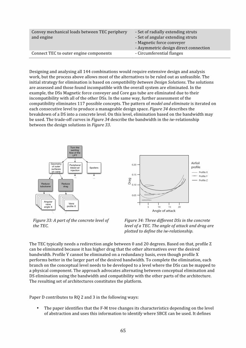
65
Convey mechanical loads between TEC periphery and engine
-‐ Set of radially extending struts -‐ Set of angular extending struts -‐ Magnetic force conveyer -‐ Asymmetric design direct connection
Connect TEC to outer engine components -‐ Circumferential flanges
Designing and analysing all 144 combinations would require extensive design and analysis work, but the process above allows most of the alternatives to be ruled out as unfeasible. The initial strategy for elimination is based on compatibility between Design Solutions. The solutions are assessed and those found incompatible with the overall system are eliminated. In the example, the DSs Magnetic force conveyer and Core gas tube are eliminated due to their incompatibility with all of the other DSs. In the same way, further assessment of the compatibility eliminates 117 possible concepts. The pattern of model and eliminate is iterated on each consecutive level to produce a manageable design space. Figure 34 describes the breakdown of a DS into a concrete level. On this level, elimination based on the bandwidth may be used. The trade-‐off curves in Figure 34 describe the bandwidth in the iw-‐relationship between the design solutions in Figure 33.
Figure 34: Three different DSs in the concrete level of a TEC. The angle of attack and drag are plotted to define the iw-‐relationship.
The TEC typically needs a redirection angle between 0 and 20 degrees. Based on that, profile Z can be eliminated because it has higher drag that the other alternatives over the desired bandwidth. Profile Y cannot be eliminated on a redundancy basis, even though profile X performs better in the larger part of the desired bandwidth. To complete the elimination, each branch on the conceptual level needs to be developed to a level where the DSs can be mapped to a physical component. The approach advocates alternating between conceptual elimination and DS elimination using the bandwidth and compatibility with the other parts of the architecture. The resulting set of architectures constitutes the platform. Paper D contributes to RQ 2 and 3 in the following ways:
• The paper identifies that the F-‐M tree changes its characteristics depending on the level of abstraction and uses this information to identify where SBCE can be used. It defines
Angle of attack
Dra
g
0.05
0.10
0.15Profile X
5 1510 20
0.20 Airfoilprofile
Profile Y
Profile Z
Turn the swirling
flow of the LPT
Peripheral bleed-air injection
SpoilersGeometry of outer surfaces on vane
Reduce tubulcene
Reduce drag
Peripheral Bleed-air injection
Vane Profile XVane
Profile XVane Profile XVane
profile X
Angular Vane
Angle X
Angular Vane
Angle X
Angular Vane
Angle X
Angular Vane
Angle X
Angular vane
angle X
... ...
iw
Figure 33: A part of the concrete level of the TEC.
66
the top level of an F-‐M structure to be static by the reason that that there are no alternative sets of solutions at this level. Consequently, SBCE has little effect here.
• At the Conceptual level, numerous platform concepts can be developed by elaborating the F-‐M structure. For each Functional Requirement, multiple Design solutions can be generated and product platform concepts are created by combining possible design solutions. One result is the combinatorial explosion that generates a large design space holding many alternative platform concepts.
• To manage this large design space the alternatives are compared and narrowed down by methods introduced in Paper D. These are based on analysis of functional relations and trade-‐off curves evaluating the compatibility between Design Solutions and their resulting bandwidth.
• The approach allows design concept exploration before committing to a platform concept which improves the support for platform development in early phases. This may ultimately produce better designs.
Paper E: Narrowing down product platforms using Set-‐based principles and Function-‐ Means modelling
Paper E presents a method, following the principles of SBCE, which narrows down the design space in early phases of platform system design. It does so specifically by introducing a way to elaborate and evaluate the properties of the functional structure and thereby capture previously unused information in early phases of development. The work introduces Architectural Options (AOs) that represent valid platform system configurations. For each AO, its internal dependencies and functional relations are modelled, quantified and visualised in an AO chart, which is used to compare the functional feasibility of the AOs. The method is based on SBCE and EF-‐M modelling. The choice of SBCE is due to its effective approach to deliver feasible solutions by gradually disregarding obviously unfeasible alternatives throughout the development process. However, when the number of alternatives to consider becomes very high, e.g. when using morphological matrices to generate design system alternatives, the solution space may become too large to manage in a set-‐based process. This challenge can be handled by using the function-‐means method to generate and structure design solution alternatives and EF-‐M system models to describe the results as functional system family architectures. These could be realized with alternative system design solutions to different functional requirements on different levels of detail and abstraction. The EF-‐M model allows dependencies, i.e. different kinds of interactions and functional couplings between different design solutions and between functional requirements and design solutions, to be modelled as relations. These can then be used to evaluate the feasibility of different system family alternatives, the AOs, on different levels of abstraction in terms of complexity and functional couplings in an axiomatic design sense. In this work AOs on the three levels of abstraction of EF-‐M trees introduced in paper D are evaluated and compared to gradually narrow down the solution space.
4.4.2 Illustrative example To illustrate the method, an example of a foot-‐controlled vehicle parking brake platform is given. The platform is modelled according to the EF-‐M methodology and the brake system is decomposed into two Functional Requirements: Regulate brake force and Create brake force. The system is subsequently broken down, as is seen in Table 9.

67
The process investigates alternative system configurations that emerge at the Conceptual level of the F-‐M tree. At the Static level there are several interactions between DS/DS and FR/DS but these do not change and can therefore not be used to evaluate different architectures. For most FRs, alternative design solutions can be found. These are placed as means in the F-‐M tree and thus represent different sets of solutions. For the vehicle brake these include both mechanical and hydraulic solutions that can be seen in Table 9. Following the establishment of the E-‐FM tree, the functional relations are identified and modelled. Two types of relations are used here to classify different couplings (see chapter 2.6). The first relation is the interacts_with (iw) relation that describes a constitutive influence between parallel solutions, where one solution creates a load (in a general sense) on the other solution, which may cause a necessary redimensioning or a redesign of the loaded solution. The second relation is the is_influenced_by (iib) relation that represents a functional coupling which exists if the constitutive influence due to the interaction results in functional interference between the interacting solutions. Here, functional couplings are defined as only those interactions where a chosen solution negatively affects the ability to fulfil the functional requirements governing a parallel FR.
4.4.3 Creating product platform architectural options The architecture of a product platform is created by the choices of possible design solutions at the conceptual level of the F-‐M tree. The FRs and DSs are clustered into logical units and the Architectural Options (AOs) are generated from the alternate Design Solutions that constitute specific system designs. Each AO leads to different functional relations in the system and the corresponding iib and iw relations are identified. Each DS is evaluated to see if it is incompatible with FRs governing parallel DSs or if it has constitutive influence on other DSs The formulation of AOs in itself is a first step to reduce the design space by eliminating unfeasible combinatorial possibilities, such as driving an electric actuator with a hydraulic power source. An example of an AO is illustrated in Figure 35.
Table 9: FUNCTIONAL REQUIREMENTS AND DESIGN SOLUTIONS FOR A VEHICLE PARKING BRAKE PLATFORM. From Paper E.
Functional Requirements Design Solution Design Solution Convert pedal force Wire brake pedal Hydraulic brake pedal Convey pedal force Wire system Hydraulic Brake line Attach pedal Brake pedal bracket Absorb energy Brake drum Brake rotor Create braking force Wire Brake shoe Brake calliper Convert force Wire Brake lining Hydraulic Brake pad Adjust force ratio Wire pedal lever arm Hydraulic pedal lever arm Connect brake wire Wire groove Connect brake line Master cylinder Convey wire pressure Wire cover Convey wire force Brake wire Convey hydraulic pressure Hydraulic fluid Enclose hydraulic pressure Brake line
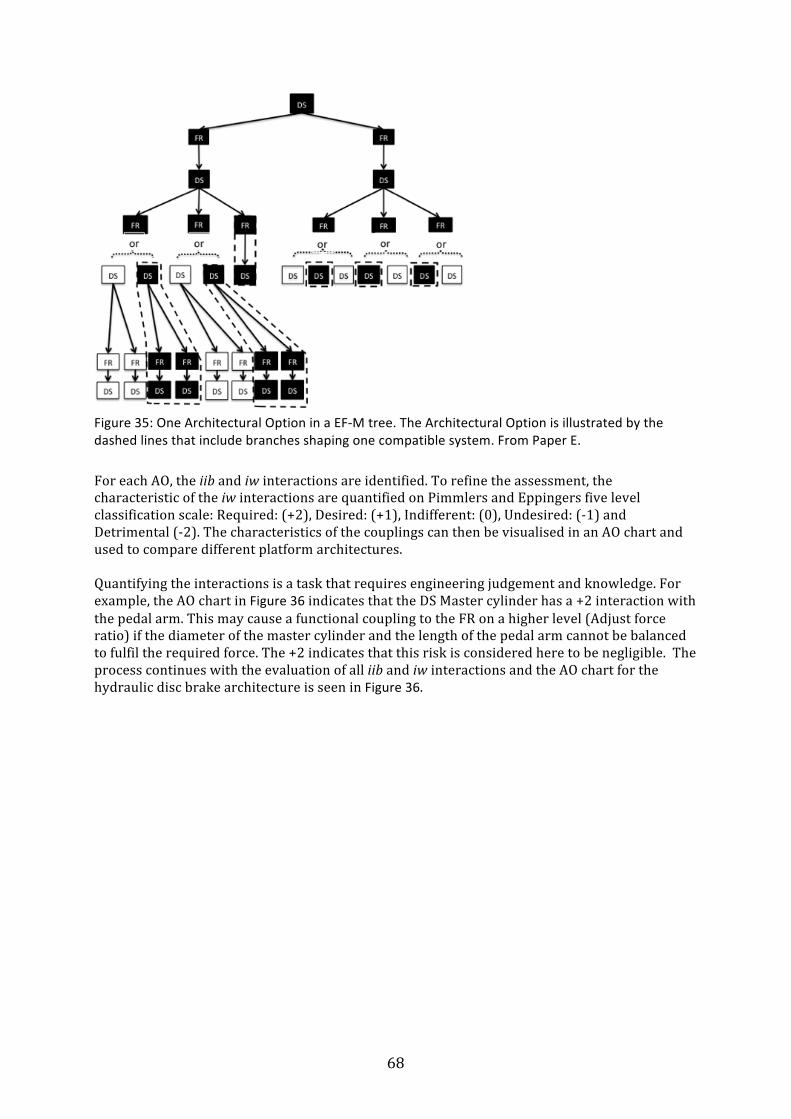
68
Figure 35: One Architectural Option in a EF-‐M tree. The Architectural Option is illustrated by the dashed lines that include branches shaping one compatible system. From Paper E.
For each AO, the iib and iw interactions are identified. To refine the assessment, the characteristic of the iw interactions are quantified on Pimmlers and Eppingers five level classification scale: Required: (+2), Desired: (+1), Indifferent: (0), Undesired: (-‐1) and Detrimental (-‐2). The characteristics of the couplings can then be visualised in an AO chart and used to compare different platform architectures. Quantifying the interactions is a task that requires engineering judgement and knowledge. For example, the AO chart in Figure 36 indicates that the DS Master cylinder has a +2 interaction with the pedal arm. This may cause a functional coupling to the FR on a higher level (Adjust force ratio) if the diameter of the master cylinder and the length of the pedal arm cannot be balanced to fulfil the required force. The +2 indicates that this risk is considered here to be negligible. The process continues with the evaluation of all iib and iw interactions and the AO chart for the hydraulic disc brake architecture is seen in Figure 36.
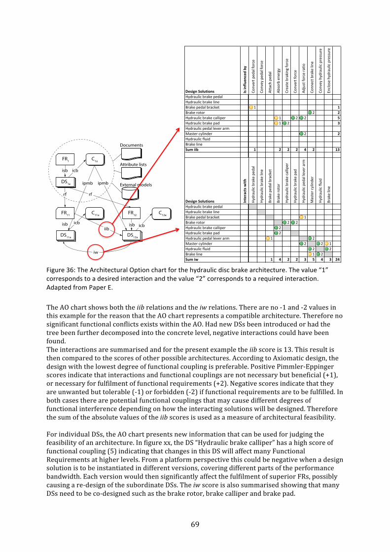
69
Figure 36: The Architectural Option chart for the hydraulic disc brake architecture. The value “1” corresponds to a desired interaction and the value “2” corresponds to a required interaction. Adapted from Paper E.
The AO chart shows both the iib relations and the iw relations. There are no -‐1 and -‐2 values in this example for the reason that the AO chart represents a compatible architecture. Therefore no significant functional conflicts exists within the AO. Had new DSs been introduced or had the tree been further decomposed into the concrete level, negative interactions could have been found. The interactions are summarised and for the present example the iib score is 13. This result is then compared to the scores of other possible architectures. According to Axiomatic design, the design with the lowest degree of functional coupling is preferable. Positive Pimmler-‐Eppinger scores indicate that interactions and functional couplings are not necessary but beneficial (+1), or necessary for fulfilment of functional requirements (+2). Negative scores indicate that they are unwanted but tolerable (-‐1) or forbidden (-‐2) if functional requirements are to be fulfilled. In both cases there are potential functional couplings that may cause different degrees of functional interference depending on how the interacting solutions will be designed. Therefore the sum of the absolute values of the iib scores is used as a measure of architectural feasibility. For individual DSs, the AO chart presents new information that can be used for judging the feasibility of an architecture. In figure xx, the DS “Hydraulic brake calliper” has a high score of functional coupling (5) indicating that changes in this DS will affect many Functional Requirements at higher levels. From a platform perspective this could be negative when a design solution is to be instantiated in different versions, covering different parts of the performance bandwidth. Each version would then significantly affect the fulfilment of superior FRs, possibly causing a re-‐design of the subordinate DSs. The iw score is also summarised showing that many DSs need to be co-‐designed such as the brake rotor, brake calliper and brake pad.
Design'Solutions' Is'influ
enced'by
Convert(p
edal(fo
rce
Convey(ped
al(fo
rce
Attach(ped
al
Absorb(ene
rgy
Create(braking(fo
rce
Convert(force
Adjust(fo
rce(ratio
Conn
ect(b
rake(line
Convey(hydraulic(pressure
Enclose(hydraulic(pressure
Hydraulic(brake(pedalHydraulic(brake(lineBrake(pedal(bracket 1 1Brake(rotor 2 2Hydraulic(brake(calliper 1 2 2 5Hydraulic(brake(pad 1 2 3Hydraulic(pedal(lever(armMaster(cylinder 2 2Hydraulic(fluidBrake(lineSum'iib 1 2 2 2 4 2 13
Design'Solutions' Interacts'w
ith
Hydraulic(brake(ped
al
Hydraulic(brake(line
Brake(pe
dal(bracket
Brake(rotor
Hydraulic(brake(calliper
Hydraulic(brake(pad
Hydraulic(ped
al(lever(a
rm
Master(cylinde
r
Hydraulic(fluid
Brake(line
Hydraulic(brake(pedalHydraulic(brake(lineBrake(pedal(bracket 1Brake(rotor 2 2Hydraulic(brake(calliper 2Hydraulic(brake(pad 2Hydraulic(pedal(lever(arm 1 2Master(cylinder 2 2 1Hydraulic(fluid 2 2Brake(line 1 2Sum'iw 1 4 2 2 3 5 4 3 24
FR1
DS1a
FR11
DS11a
C11a
C1a
FR12
DS12a
C12a
Documents
Attribute lists
External models
isb isb
isb
rf rf
icbicb
icb
iib
ipmb ipmb
iw
FR
DS
C
isb: An FR “is_solved_by” a DS
rf: A DS “requires_fuction” FR
icb: A DS “is_constrained_by” a C
ipmb: A C “is partly_met_by” a DS
iib: Fulfillment of an FR “is_influenced_by” a DS
iw: A DS “interacts_with” a DS
Functional requirement
Design solution
Constraint
70
Comparing the AO charts for all architectures will pinpoint the architectural option that has a high degree of functional dependencies and therefore can be eliminated. The remaining set of architectural options constitutes the platform that is further developed with traditional engineering tools. The contributions of Paper E to RQ2 and RQ3 can be summarised as:
• Paper E presents a way to manage sets of functional platform concepts. It introduces the concept of Architectural Options to divide the architectures into feasible types. For each Architectural Option, a chart can be created that clarifies the functional couplings and interactions within an EF-‐M model, thereby communicating the properties of different architectures.
• The method increases the amount of information that can be captured in early phases of development by elaborating the relations within the EF-‐M model. It assesses the severity of the constitutive influence between parallel solutions as well as the functional couplings between solutions and functional requirements. Knowledge about the different architectures is therefore enhanced without the need for conceptual design and analysis.
• This increased information is used to narrow down the design space and the conceptual robustness of the architectures is assessed by analysing the complexity of the individual architectures through the relations of the EF-‐M model. . The relations are scored and compared across architectures, thereby risky, highly coupled architectures and design solutions can be avoided.
4.5 Paper F: Modelling and assessing platform architectures in early phases through Set-‐based evaluation and change propagation.
Paper F presents methodological support for the establishment of platform architectures in the earliest phase of development. It elaborates on the results presented in paper D and E, by adding an architectural view and new ways to evaluate platform architectures using a methodology from another research domain. The support is illustrated with a case from the aerospace industry showing how a manufacturer of parts for a jet engine can use the methodology to redesign a platform concept. In the formulation and embodiment of a product platform, many decisions are made and assumptions established with little methodological support. Paper F addresses this need by presenting a method for modelling, analysing and assessing products and platform architectures in the Pre-‐embodiment phase that foregoes the embodiment and elaboration of ideas into concepts. It allows exploration of more alternatives in the earliest phases of development, which ultimately may produce better designs. The result is a design space of a manageable and desirable size for subsequent embodiment and detailed design with traditional engineering tools. The advantage is that feasibility of the candidate platforms has been established to a high degree of certainty The Pre-‐embodiment phase focuses on context analysis rather than content analysis. The approach of Paper F analyses the functional architecture in the form of functional requirements and design solutions instead of the resulting designed architecture, as is the case for traditional engineering analysis. The reason for choosing the functional architecture as the unit of analysis is that the functions of an artefact are a key concept for knowledge about products and systems.
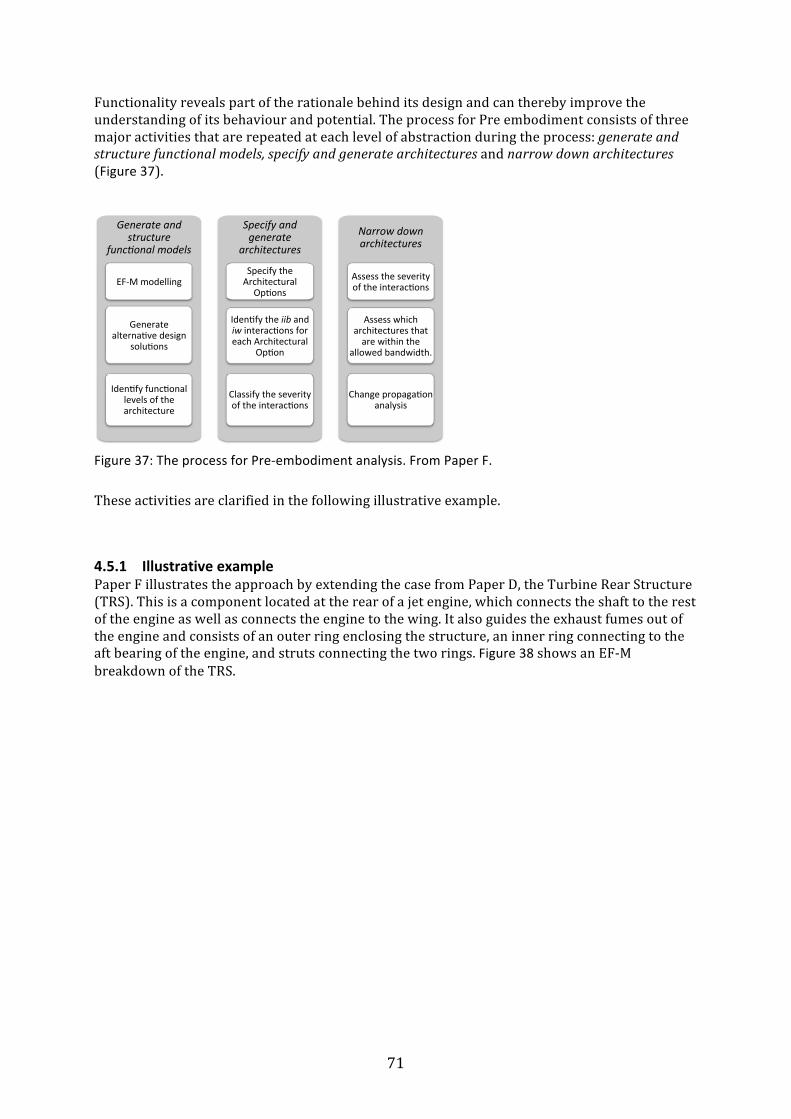
71
Functionality reveals part of the rationale behind its design and can thereby improve the understanding of its behaviour and potential. The process for Pre embodiment consists of three major activities that are repeated at each level of abstraction during the process: generate and structure functional models, specify and generate architectures and narrow down architectures (Figure 37).
Figure 37: The process for Pre-‐embodiment analysis. From Paper F.
These activities are clarified in the following illustrative example.
4.5.1 Illustrative example Paper F illustrates the approach by extending the case from Paper D, the Turbine Rear Structure (TRS). This is a component located at the rear of a jet engine, which connects the shaft to the rest of the engine as well as connects the engine to the wing. It also guides the exhaust fumes out of the engine and consists of an outer ring enclosing the structure, an inner ring connecting to the aft bearing of the engine, and struts connecting the two rings. Figure 38 shows an EF-‐M breakdown of the TRS.
Narrow&down&architectures!
Specify&and&generate&
architectures&!
Generate&and&structure&
func6onal&models!
EF$M!modelling!Specify!the!Architectural!
Op:ons!
Iden:fy!the!iib!and!iw!interac:ons!for!each!Architectural!
Op:on!
Assess!which!architectures!that!are!within!the!
allowed!bandwidth.!
Assess!the!severity!of!the!interac:ons!
Change!propaga:on!analysis!
Generate!alterna:ve!design!
solu:ons!
Iden:fy!func:onal!levels!of!the!architecture!
Classify!the!severity!of!the!interac:ons!
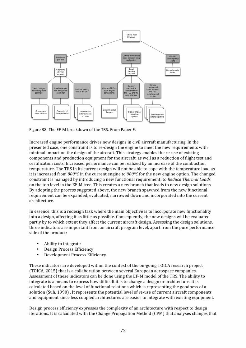
72
Figure 38: The EF-‐M breakdown of the TRS. From Paper F.
Increased engine performance drives new designs in civil aircraft manufacturing. In the presented case, one constraint is to re-‐design the engine to meet the new requirements with minimal impact on the design of the aircraft. This strategy enables the re-‐use of existing components and production equipment for the aircraft, as well as a reduction of flight test and certification costs. Increased performance can be realized by an increase of the combustion temperature. The TRS in its current design will not be able to cope with the temperature load as it is increased from 800°C in the current engine to 900°C for the new engine option. The changed constraint is managed by introducing a new functional requirement; to Reduce Thermal Loads, on the top level in the EF-‐M tree. This creates a new branch that leads to new design solutions. By adopting the process suggested above, the new branch spawned from the new functional requirement can be expanded, evaluated, narrowed down and incorporated into the current architecture. In essence, this is a redesign task where the main objective is to incorporate new functionality into a design, affecting it as little as possible. Consequently, the new designs will be evaluated partly by to which extent they affect the current aircraft design. Assessing the design solutions, three indicators are important from an aircraft program level, apart from the pure performance side of the product:
• Ability to integrate • Design Process Efficiency • Development Process Efficiency
These indicators are developed within the context of the on-‐going TOICA research project (TOICA, 2015) that is a collaboration between several European aerospace companies. Assessment of these indicators can be done using the EF-‐M model of the TRS. The ability to integrate is a means to express how difficult it is to change a design or architecture. It is calculated based on the level of functional relations which is representing the goodness of a solution (Suh, 1990) . It represents the potential level of re-‐use of current aircraft components and equipment since less coupled architectures are easier to integrate with existing equipment. Design process efficiency expresses the complexity of an architecture with respect to design iterations. It is calculated with the Change Propagation Method (CPM) that analyses changes that
Lead core gas flow
Convey mechanical loads between wing
and engine
Contain disintegrating
parts
Lead core gas flow along inner
perimeter
Geometry of inner surfaces
Lead core gas flow along outer
perimeterTurn the swirling flow of the LPT
Load bearing structure
Circumferential barier
Convey mechanical
loads between the TEC
periphery and engine
Convey mechanical
loads between the TEC and the wing interface
Connect TEC to outer engine components
Turn the swirling flow of
the LPTGeometry of
outer surfaces
Turn the swirling flow of
the LPTGeometry of
inner perimeter
Turn the swirling flow of
the LPTTurn the
swirling flow of the LPTGeometry of
outer surfaces on vane
Turn the swirling flow of
the LPTTurn the
swirling flow of the LPT
2-point engine mounting system
Turn the swirling flow of
the LPTTurn the
swirling flow of the LPT
Turn the swirling flow of
the LPT
Circumferential flanges
Sets of radially extending struts
Turbine Rear Structure
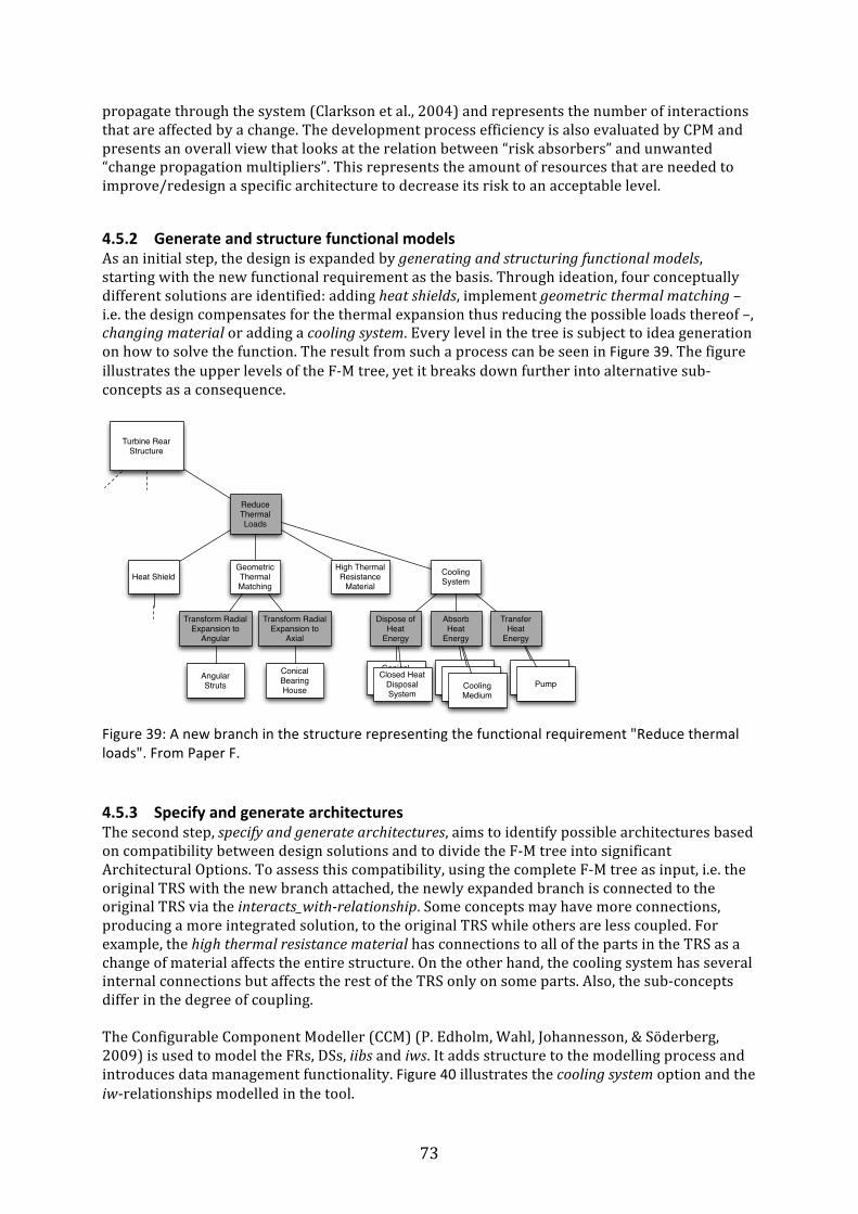
73
propagate through the system (Clarkson et al., 2004) and represents the number of interactions that are affected by a change. The development process efficiency is also evaluated by CPM and presents an overall view that looks at the relation between “risk absorbers” and unwanted “change propagation multipliers”. This represents the amount of resources that are needed to improve/redesign a specific architecture to decrease its risk to an acceptable level.
4.5.2 Generate and structure functional models As an initial step, the design is expanded by generating and structuring functional models, starting with the new functional requirement as the basis. Through ideation, four conceptually different solutions are identified: adding heat shields, implement geometric thermal matching – i.e. the design compensates for the thermal expansion thus reducing the possible loads thereof –, changing material or adding a cooling system. Every level in the tree is subject to idea generation on how to solve the function. The result from such a process can be seen in Figure 39. The figure illustrates the upper levels of the F-‐M tree, yet it breaks down further into alternative sub-‐concepts as a consequence.
Figure 39: A new branch in the structure representing the functional requirement "Reduce thermal loads". From Paper F.
4.5.3 Specify and generate architectures The second step, specify and generate architectures, aims to identify possible architectures based on compatibility between design solutions and to divide the F-‐M tree into significant Architectural Options. To assess this compatibility, using the complete F-‐M tree as input, i.e. the original TRS with the new branch attached, the newly expanded branch is connected to the original TRS via the interacts_with-‐relationship. Some concepts may have more connections, producing a more integrated solution, to the original TRS while others are less coupled. For example, the high thermal resistance material has connections to all of the parts in the TRS as a change of material affects the entire structure. On the other hand, the cooling system has several internal connections but affects the rest of the TRS only on some parts. Also, the sub-‐concepts differ in the degree of coupling. The Configurable Component Modeller (CCM) (P. Edholm, Wahl, Johannesson, & Söderberg, 2009) is used to model the FRs, DSs, iibs and iws. It adds structure to the modelling process and introduces data management functionality. Figure 40 illustrates the cooling system option and the iw-‐relationships modelled in the tool.
Reduce Thermal Loads
High Thermal Resistance
Material
Turbine Rear Structure
Geometric Thermal Matching
Heat Shield Cooling System
Dispose of Heat
Energy
Absorb Heat
Energy
Transfer Heat
Energy
Transform Radial Expansion to
Angular
Transform Radial Expansion to
Axial
Angular Struts
Conical Bearing House
Conical Bearing House
Closed Heat Disposal System
Cooling MediumCooling
MediumPump
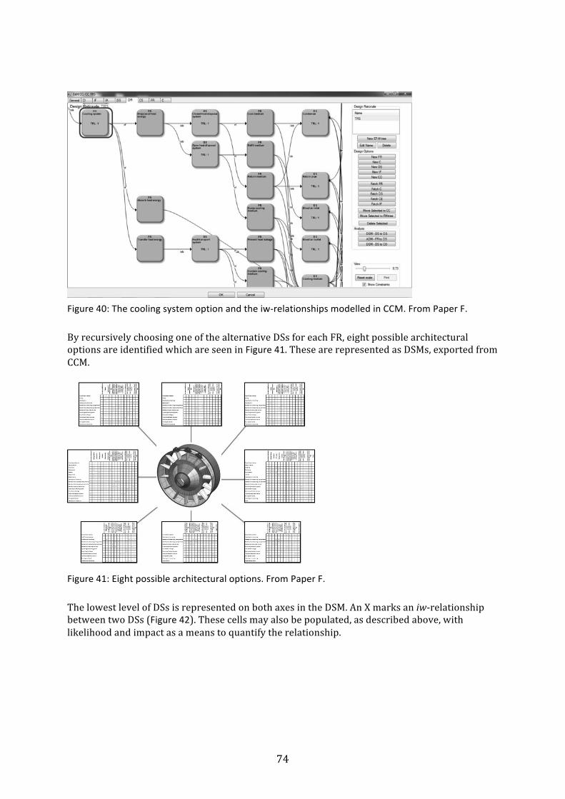
74
Figure 40: The cooling system option and the iw-‐relationships modelled in CCM. From Paper F.
By recursively choosing one of the alternative DSs for each FR, eight possible architectural options are identified which are seen in Figure 41. These are represented as DSMs, exported from CCM.
Figure 41: Eight possible architectural options. From Paper F.
The lowest level of DSs is represented on both axes in the DSM. An X marks an iw-‐relationship between two DSs (Figure 42). These cells may also be populated, as described above, with likelihood and impact as a means to quantify the relationship.

75
Figure 42: One of eight possible architectural options represented as a DSM. From Paper F.
In this example, the values are set at the neutral level of 0,5 for likelihood and impact, which is appropriate for identifying promising regions of the design space. These values can also be modified for design space exploration and “what-‐if” studies. Finding more precise values requires extensive experience and engineering work, which is not the scope for the Pre-‐embodiment phase. However, the numbers for likelihood and impact can be reused from related architectures once they are established which is subject to on going research (TOICA, 2015).
4.5.4 Narrow down architectures In the definition of AOs, the alternatives that are not compatible are already eliminated. Still, the eight remaining architectural options constitute a design space too great to embody and analyse. It is therefore desirable to narrow down these further. As the third step is initiated, the eight architectures are narrowed down to a select few. Inferior architectural options are eliminated based on functional couplings. These are extracted from the DSMs and are compared across architectures as a measurement of complexity. A more coupled architectural option affects the ability to integrate high-‐level requirement, and is thus considered harder to develop in detailed design. The analyses show that six out of the eight architectures have 26 or 27 couplings, whereas the remaining two have 35 and 40 respectively. The difference is not considered significant as the only elimination criterion at this level of abstraction and all options are kept in the set of active solutions until more information is available. Had the system been further decomposed, larger differences could have been found. Also the performance in the terms of bandwidth can be used for narrowing. In the present case, the model is not developed to an extent that allows comparing the bandwidths, and this is therefore not used for elimination. Further analysis of the functional architecture can be performed in different ways and the present example utilizes change propagation analysis on the DSMs by the Change Propagation Method (Clarkson et al., 2004). The parts of a system interact with each other and a change to one part of a system may therefore require changes to other parts to fulfil the requirements. When such a change or a new solution is introduced in a system, it can initiate a flow of unplanned changes that propagates through the system. Most importantly, the Change Propagation Method can reveal the region(s) of a system that is not explicitly connected with the change, although significantly influenced.
Circumferential-barrier
Cooling-Medium
Condenser
Return-pipe
Pipin
g-system
Isolation
Mounting-rim-in-inner-ring
Geom
etry-of-surfaces-along-
inner-perim
eter
Geom
etry-of-surfaces-along-
outer-perim
eter
Geom
etry-of-outer-surface-
on-vane
3<point-engin
e-mounting
-system
Circumferential-flanges
Outer-circum
ferential-
structure
Inner-circum
ferential-
structure
Strut-segm
ent-(vane)
Mounting-rim-in-outer-ring
Pump
Circumferential-barrier xCooling-MediumCondenser x x xReturn-pipe x x xPiping-system x x x x x x xIsolation xMounting-rim-in-inner-ring x x xGeometry-of-surfaces-along-inner-perimeter x xGeometry-of-surfaces-along-outer-perimeter x xGeometry-of-outer-surface-on-vane x x x3<point-engine-mounting-system xCircumferential-flanges xOuter-circumferential-structure x x xInner-circumferential-structure xStrut-segment-(vane) x x xMounting-rim-in-outer-ring x x x xPump x x

76
The DSMs are analysed for sensitivity to changes in the structure using the Cambridge Advanced Modeler (Wynn, Wyatt, Nair, & Clarkson, 2010). The data is prepared according to the Value Driven Design methodology presented by Kipouros and Isaksson (2014) and translated to the three indicators presented above-‐ ability to integrate, design process efficiency and development process efficiency, and plotted in Figure 43.
Figure 43: Plot of the eight architectural options after going through change propagation analysis and transformation to the assessment criteria. Architectures number 2 and 3 have identical values; thereby only seven data points are plotted. The higher values the better. From Paper F.
Examining the plot in Figure 43, a cluster of architectures having similar values for the high-‐level assessment criteria is found. The two remaining alternatives have different properties. In the present case, the ability to integrate is highly important but the values are not sufficiently differentiated. It is clear that a “best” alternative cannot be selected out of this information, unless the priority between criteria is clear. Looking at the other indicators, the two alternatives with a low score on Design process efficiency might be eliminated, and the remaining architectures kept for further development, assessment and evaluation. The contribution of Paper F to RQ2 and RQ3 can be summarised in the following way:
• A support for product or platform development in the phase foregoing concept design is
presented. Here, many decisions are made and assumptions established with little methodological support and this paper presents a methodology that fills this void.
• It uses the software CCM to model and synthesise the functional design space that is divided into discrete Architectural Options each holding one platform variant. The functional relations within each Architectural Option are packaged in DSM matrixes that can be used for further analysis by other tools.
• The DSMs are analysed with the Change Propagation Method and the results are mapped onto high-‐level objectives according to the Value Driven Design process (VDD). This way of working enables VDD in the earliest phase of development where the data typically required for modelling and simulation of product properties used in VDD is unavailable.

77
5 Discussion In this chapter the research questions are answered. Moreover, the contributions and the quality of the results in relation to the research approach used are discussed.
5.1 Answering the research questions The research questions are partly overlapping where Research Question 1 essentially is aimed at developing understanding of SBCE while Research Question 2 focuses on the unique way that SBCE handles alternative solutions. Research Question 3 aims at developing support for the earliest phases of platform development based on the principles of SBCE. RQ 1: How do the principles of SBCE affect industrial product development and its
performance in different environments? The first Research Question has several dimensions and includes how SBCE can be introduced to support industrial product development and how it affects the development process and the resulting products. Means needed to introduce the principles of SBCE are addressed in Papers A and C, D and F, even though all papers touch upon the pursuit of introducing SBCE. Paper A contributes to the research question by presenting a way to introduce SBCE though pilot projects. It shows that Set-‐based projects can be implemented within an organization practicing traditional Point-‐based development without fundamental changes in the organisation. This finding is not evident since (Morgan & Liker, 2006)p. 283 and M. Kennedy et al. (2008) describes SBCE as challenging to apply. It further clarifies factors that need to be considered in order to make a successful introduction in different environments. Paper C presents a morphological approach that follows the principles of SBCE. The contribution is a methodology and a computer tool to enable SBCE in traditional product development and the applicability is demonstrated with an example form industry. Furthermore, Papers D and F contribute by presenting support for early platform development built on the Set-‐based principles and Enhanced Function-‐Means modelling. The support is developed in collaboration with industry and applied in a project (TOICA, 2015), although not evaluated in a completed project. The main contribution to clarifying the effects on the products is found in Paper A which addresses the effects on the products by applying the principles of SBCE in industrial product development. Paper A shows that SBCE gives positive effects on the resulting products, well aligned to previous literature. The effects are especially dominant on product performance, product cost and the level of innovation. Moreover, the design decision process has important effects on the products. Paper B reports that SBCE creates different design decisions and consequently this will affect the resulting products. For the effect on the development process, Papers A and B reports the results from industrial product development. The positive effects reported in Paper A were achieved at the expense of slightly lower efficiency, measured in the terms of development costs and lead-‐time. This lower efficiency is not consistent with prior art and the reasons are not fully clarified. Part of this discrepancy may be accounted for by the uncertainty in the way costs and lead-‐time are compared over projects. Another reason is the additional resources needed to start working in a new way, as stated by the participating firms. Moreover, the development of solutions that are eliminated and not used in the projects will cost resources. These solutions may be reused in future projects provided that necessary knowledge management means are implemented.

78
The effects that come from introducing the new tools and methodologies suggested in Papers C-‐F are difficult to apprehend beforehand. One potential positive effect is that the knowledge management need identified in Paper A can be improved by the EF-‐M model. As stated by V. Hubka and Eder (2001), functionality is an important key to knowledge about products and systems and the EF-‐M model represents a de-‐facto map of the design rationale in the form of its functional requirements and design solutions. In summary, the research question can be answered with the limitations outlined above. The principles of SBCE can be introduced in other environments than the primary studies with dominating positive effects, provided that the applicability of the suggested processes and tools is considered in each development context. RQ2: How can the principles of SBCE be applied to identify feasible regions of the design
space and support convergence to feasible solutions? The way that SBCE can narrow down the design space is one of its most characteristic differences from point-‐based development. It includes both clarifying how decisions are made and how requirements are handled and evolved. Consequently, this research question is touched upon in all papers. Paper A states that the Set-‐based decision process basically is a rejection process of the least suitable solutions rather than a selection process based on estimates of future properties. SBCE carries forward all alternatives that cannot yet be eliminated and earlier studies state that Set-‐based decisions are made in different ways compared to traditional Point-‐based decisions. Paper B corroborates this claim and further demonstrates how Set-‐based decisions can generate disparate results compared to traditional matrix evaluations. The study is based on an industrial case study, which concludes that one important difference between the approaches is that the traditional decision process is unable to both identify and request the critical information needed to make good decisions. In SBCE, alternatives that cannot be eliminated stays in the sets until adequate information is obtained. To converge to a solution, this information must be actively sought after which is a somewhat different task than estimating the properties of a future design solution. Estimates rely heavily on personal judgement and experience that makes the outcomes dependent on the individuals involved and also affects the reported study. Claims that the SBCE decision process is superior to other approaches cannot be made based on one case, although the industrial partner preferred the results from the Set-‐based approach. The results are consistent with the principles of SBCE and the approach could therefore be applicable in similar situations. A way to introduce the Set-‐based decision process is presented in Paper C where it is implemented in a process and computer tool. It supports a step-‐vice evolution of requirements and allows designs to evolve with increased level of detail, promoting the elimination of the least suitable solutions instead of selecting the best solution. The process is demonstrated by data from an industrial project. Papers D, E and F focuses on support for early phases of product platform development that also should be applicable for single product development, although not explicitly targeted. These papers present a collection of approaches that aims at identify promising regions of the design space and to converge towards feasible solutions. The result is a design space of a desirable size that is manageable in subsequent phases. In Paper D, one contribution is definition of three abstraction levels in EF-‐M structures that clarify where convergence is applicable. One conclusion is that no elimination of solutions is possible at the most abstract static level, since

79
this holds functional requirements that are part of the core business and must be fulfilled. Paper D also contributes with methods to narrow down the design space based on how well a DS covers the desired bandwidth of an FR, or based on individual DSs compatibility with the system. Functionality is further elaborated in Paper E by introducing Architectural Options that divide the design space into significantly different platform types, thereby eliminating the alternatives that fall outside these architectures. The functional characteristics of these options are further assessed through the distinctive functional relations of each architecture, thereby enabling the elimination of the least feasible alternatives. Paper F contributes with an architectural view on platform development for the phase that foregoes the embodiment and elaboration of ideas into concepts. Following the generation of alternatives and the elimination steps described in Paper D and E, the paper introduces the Change Propagation Method that makes new types of analysis on the functional relations. This information is used to further narrow down the design space, as is demonstrated by an example developed in collaboration with industry. Summarising the discussion, the presented research offer possible approaches to support design convergence by applying the principles of SBCE to product platforms and single products with the reservations outlined above. RQ3: How can methods and tools derived from SBCE and EF-‐M modelling be used to
find feasible system architectures and function realizing features in early phases of product and platform development?
One of the most critical steps when developing new products and systems is in the establishment of a system layout or platform architecture. For this, current methodology is undeveloped and RQ3 aims at creating support for this abstract phase of development. The underlying assumption is that the principles of SBCE also are efficient for platform based development. The main contribution is found in papers D and F, with supporting tools developed in Paper E. An additional contribution is that papers D and F provide a new way to use SBCE by applying it to the Pre-‐embodiment phase of development. The transition from a component based to a functional based perception of products and platforms presents new opportunities in the early phases of development. Paper D presents a process and model where the chosen way of modelling with Function-‐Means allows several alternative designs in the platform, which increases the chances for creating feasible solutions within the design space. Methodologies that are relevant for the platform development process are presented and by analysing an industrial example the work presents a way that companies can take toward integrating the principles of SBCE in platform-‐based development. To improve the assessment process and thereby the resulting design convergence, Paper E elaborates the functional relations in the EF-‐M model by quantifying the severity of the lateral relationships in the form of interacts_with and is_influenced_by couplings. It enhances the information generated in the process presented in Paper D, thereby may better design decisions be made during preliminary embodiment. Paper E also introduces Architectural Options charts that make it possible to compare sets of functional architectures to each other. Paper F elaborates the process in Paper D for architectural exploration by preparing information about the possible architectures in a way that allows for subsequent analysis in other tools. The results are Design Structure Matrixes holding the functional relations. These can be exported for different types of analysis. In Paper F, an example of analysis using the Change Propagation method is given and the result is that the architectures can be mapped against the fulfilment of high-‐level objectives of the platform. By providing preference information between these high-‐level objectives, a number of alternatives can be eliminated. The results of Paper F are
80
implemented in an on-‐going research within the European aerospace industry (TOICA, 2015) aiming at providing better information to base design decisions on in the Pre-‐embodiment phase. In summary, the here presented research presents one possible approach to generate, evaluate and narrow down sets of platform system architectures. It hereby answers the research question within the limitations and possibilities presented above.
5.2 RESEARCH EVALUATION
The contribution has to be evaluated by addressing its quality. Following the discussion in section 3.4, the terms validation and verification are within this research seen as separate constructs that are used together for assessing the quality of the research. Unfortunately, these terms are used differently within different research disciplines and in this work validation seek to answer the question “Have we done the right things?” whereas verification seek to answer the question “Have we done things in the right way?”. The presented research is evaluated by the approaches given in (Buur, 1990) and Cross (2007).
5.2.1 Evaluating the research according to Buur
Buur (Buur, 1990) proposes two ways to evaluate the quality of design theories: logical verification and verification by acceptance. Logical verification evaluates the reliability of the results. It considers the methodological rigor and theoretical consistency within the research as well as the consistency with the results from external research. Verification by acceptance focuses on having new scientific results accepted by researchers or experienced designers within the field, which in this thesis is denoted as the validity of the approach.
The results in the papers are verified by acceptance by different means and the criteria are seen here as corroborating the validity of the results rather than representing the absolute truth. All results are verified through the peer review in the publication process, where experts in respective fields assess the quality of the results. Papers A and F were published by journals and Papers B, C, D and E were published in conference proceedings.
Verification of the results from Papers A, B, D and F is also done in different ways by the industrial partners, demonstrating that the models and methods derived from the theory of SBCE are acceptable to experienced designers. In Paper A, the respondents state that they will continue to use SBCE in the future when appropriate. Moreover, one of the firms has implemented a new design process in the whole organization based on LPD and SBCE and has trained most of its staff in the fundamentals of SBCE and LPD. In Paper B, the benefits of the SBCE decision process were corroborated in a case study when the firm preferred the alternatives promoted by the Set-‐based decisions. The question of whether the results drawn from Paper B are applicable to other development projects or firms cannot be answered without further studies, but the principle of elimination as a decision method is also suggested by Roozenburg and Eekels (1995).
The modelling approach presented in Papers D and F agrees with established design theory presented by M. Myrup Andreasen (1980), Mortensen (1999) and Suh (1990). Verification of the results from Papers D and F is also demonstrated by its acceptance within an on-‐going collaboration project in European aerospace industry (TOICA, 2015), even though no products are yet developed following this approach. Here, the platform modelling technique, the narrowing strategy and the accompanying Configurable Component Modeller IT tool is used in the early development phases for the next generation of jet planes. Specifically the management of functional information is seen as a valuable addition to traditional engineering tools.
81
Papers C and E are not based on projects involving professional engineers and must therefore be logically verified. The research is based on known models and literature and the results are found to be consistent with established literature and related results:
The results presented in Paper C can be logically verified since the proposed process and computer tool are consistent with the use of Morphological matrixes and the grounds of SBCE. The suggested process in Paper C delays design decisions until sufficient knowledge about the design and requirements is available to eliminate the weakest alternatives. This approach is consistent with A. Ward et al. (1995), stressing the importance of delaying decisions. Moreover, the presented case study also demonstrates the process’s coherence to the three principles of SBCE.
The results in paper E are consistent with known theories: The modelling approach is, in essence, an application of function-‐means modelling and no conflicts emerged between the EF-‐M model, the model of Pimmler and Eppinger (1994) and the principles of SBCE. Using functional couplings to assess the quality of a design is also in line with the work of Suh (1990). Moreover, the concept of functional modelling in early phases of platform development is also suggested by Farrell and Simpson (2003).
Looking at the completeness of the research, the results are in agreement with the respective theory for the represented cases. In Paper A, the results show that the SBCE increases lead-‐time and is more expensive which is a deviation from theory (Morgan & Liker, 2006; A. Ward et al., 1995; Allen C. Ward & Sobek, 2014). The respondents, however, state that for future projects, the organization will learn the new practices and therefore work faster. Furthermore, reservations must be considered regarding the results drawn from the selection companies. Nevertheless, for the cases presented, the firms represent a wide selection of industries, working in the businesses of aerospace, electronic systems, graphic industry, automotive supplies and heavy trucks. The size of the companies also represents a broad range, varying between 100 and 30 000+ employees. This indicates that the results are useful to other companies.
5.2.2 Evaluating the research according to Cross
Cross (2007) p.48 presents a list of best practice for valid design research (see chapter 3). These criteria are seen as indicators of the quality of the research that should have the characteristics of table 5.1 below. The first three indicators concern the relevance for the problem addressed (validation) and the last two indicators concern methodological and theoretical consistency (verification). Descriptions of the way that the presented research meets these indicators are also given in the table.
Table 10: Indicators for valid design research according to Cross and the
corresponding confirmation from the presented research. Indicators Fulfilment
Purposive – based on identification of an issue or problem worthy and capable of investigation
The need for more efficient design methodologies, especially the stated high efficiency of SBCE
Inquisitive – seeking to acquire new knowledge
Filling known research gaps on the effects and practical application of SBCE and early platform development
82
Reflecting upon the evaluation of the research results and the research approach, the criteria proposed by Buur and Cross are generally met by the work presented here. These criteria are seen as indicators and not as representing an absolute truth. Consequently, before applying the proposed tool and models created in this research, the users must evaluate whether the results are relevant for their specific context and challenges. The chosen applied research approach, the Design Research Methodology (Blessing & Chakrabarti, 2009), as well as Buur’s and Cross’ criteria for evaluation of design research (Buur, 1990; Cross, 2007) are frequently used in the type of work presented in this thesis. This type of evaluation is further corroborated by K. Pedersen, Emblemsvåg, Bailey, Allen, and Mistree (2000), where several criteria for research validation are linked to its usefulness with respect to a purpose. Likewise, Eckert et al. (2004), p. 6, state that “The most useful criterion for success is the perception of value in new procedures and methods by design practitioners in industry”. The conclusion is that these quality indicators are also relevant for assessing the quality of the presented research approach and results. Given the above ways to validate research results and approaches, the following concluding remarks are made to support the validity of the results of this thesis: The research process used several data sources including process descriptions, drawings and project related documents. Interviews, workshops as well as web meetings were held with individuals from different departments and holding different roles in the companies. The results were obtained in collaboration with five different companies representing a broad selection of industries working in different businesses. Development of methodology was also made in a consortium including several universities and aerospace companies across Europe, where the results were demonstrated and approved. The diverse character of companies and applications indicates that the results are valid and useful also in other contexts.
Informed – conducted from an awareness of previous, related research
Thorough review of state-‐of-‐the-‐art
Methodical – planned and carried out in an efficient and disciplined manner
The applied research methodology, DRM. Interviews and industrial collaboration carried out in a methodical, traceable manner
Communicable – generating and reporting results which are testable and accessible by others.
Peer-‐reviewed publications and presentations of the results to the industrial partners, specifically within the Wingquist Laboratory

83
6 Conclusions and future work Based on the results and their quality as discussed in the previous chapter, a number of conclusions can be drawn. Furthermore, the remaining research gaps are discussed and suggestions for future work are presented.
6.1 Conclusions: The presented research clarifies that the three principles of SBCE give positive effects on many aspects of product development performance, which could be predicted from current theories. It also shows that Set-‐based projects can be implemented within an organization practicing traditional Point-‐based development without fundamental changes in the organisation. For this result to be valid, the three principles of SBCE must be interpreted in the context of a specific organisation’s design processes. Proper support and attention from the management, as well as changes to the development process in the early phases of development is also required. The results are based on studies of product developing companies having different sizes, products and methods of working. This indicates that the conclusions are applicable also to wider range of product developing industry outside the studied companies. The way that SBCE can narrow down the design space is one of the most characteristic ways that SBCE distinguishes itself from Point-‐based development and earlier studies state that Set-‐based decisions are made in different ways. This thesis corroborates this claim and further demonstrates how Set-‐based decisions can generate different results compared to traditional Point-‐based decisions. Claims that the SBCE decision process is superior to other approaches cannot be made without further studies. This thesis further presents means to introduce design support based on the principles of SBCE intended for both platform modelling and for single product development. Supporting tools and methods are developed that can generate and narrow down the design space. The generation of solutions is supported by a morphological approach that can create a large design space and design convergence is supported by several means eliminating unfeasible solutions based on compatibility, performance and functionality. The support for platform development is based on Enhanced Function– Means modelling. Several approaches for design convergence are presented in which the functional relations of the models are used to identify promising regions of the design space and to gradually narrow this down. These are based on functional analysis of the model and also supplemented with the Change Propagation Method to elaborate the information that can be captured in the early phases of development. Lastly, this thesis contributes with a new application of SBCE for architectural exploration of platforms. Previous SBCE literature describes how knowledge of the design space is gained through evaluation of concrete designs in the form of sketches, drawings, simulations or by prototype testing. The presented support can generate knowledge of the design space without the need for physical or virtual testing. It is applied in the first phase of development and is based on Enhanced Function– Means modelling. It uses the functional characteristics of multiple platform options to evaluate and eliminate sets of platform concepts according to Set-‐based principles. Unfeasible alternatives can thereby be eliminated in early design phases long before physical prototypes are available.

84
6.2 Future Work Applying Set-‐based approaches in development projects has created new knowledge of SBCE. In Paper A, the companies report that the level of innovation is improved in the pilot projects. This is an important observation and further investigations are needed in order to clarify if improved innovation abilities are a characteristic feature of SBCE. Another important observation is that Paper B concludes that SBCE can promote different design decisions compared to traditional methods. Studies of evaluation principles have a universal importance in engineering design and efforts should be made to better understand the SBCE assessment and elimination process. More work is therefore needed to verify and to generalise the results from Paper B in other cases. Knowledge management is also of great importance in engineering design. SBCE creates an extensive amount of design knowledge that needs to be managed, making this aspect more important than in traditional development. Future research should therefore study how the EF-‐M platform model can support knowledge development and management of design knowledge since this is not investigated in this work.
For product platforms, the design processes described in Papers D and F should be evaluated in more ways. It should be tested in industrial case studies involving professional engineers and also be applied in cases with less integrated products. Additionally, more work is needed to improve the suggested assessment methods. The amount of information used for assessment in Paper E could be increased by also evaluating different classes of relations such as spatial interactions, energy-‐, material – and information exchange. The information should be integrated in the Configurable Component Modeller IT tool to automate the scoring and visualising of the Architectural Options, which could improve the ease and quality of the convergence process. Also the appropriate values for likelihood and impact in the change Propagation Method needs to be further investigated. The new design methodology for managing the architectural design space is currently subject to on going research within the aerospace industry and hopefully the results presented in this thesis will contribute to better products in the future. “Det mesta är ännu ogjort, underbara framtid!” Ingvar Kamprad, IKEA founder, 1976

85
7 References Al-‐Ashaab, Ahmed, Golob, Matic, Attia, Usama M, Khan, Muhammad, Parsons, Jon, Andino,
Alberto, . . . Kesavamoorthy, Sivatharan. (2013). The transformation of product development process into lean environment using set-‐based concurrent engineering: A case study from an aerospace industry. Concurrent Engineering, 1063293X13495220.
Andreasen, M. M. , & Hein, L. . (1997). Integrated Product Development. New York, New York, USA: Springer.
Andreasen, M. Myrup. (1980). Syntesemetoder på Systemgrundlag – Bidrag til en konstruktionsteori. (Doctoral Thesis), Lund Technical University, Lund, Sweden.
Andreasen, M. Myrup. (1998). Reduction of the complexity of product modelling by modularization. Paper presented at the Conference on product models, Linköping, Sweden.
Ash, R.L., Britcher, C.P., Hyde, K.W. . (2003). prop-‐Wrights-‐ How two brothers from Dayton added a new twist to airplane propulsion. . Mechanical Engineering(Special issue 100 years of flight).
Berglund, Fredrik, & Claesson, Anders. (2005). Utilising the Concept of a Design's Bandwidth to Achieve Product Platform Effectiveness. Paper presented at the Proceedings of ICED 2005, Melbourne, Australia.
Bernstein, J. I. (1998). Design Methods in the Aerospace Industry: Looking for Evidence of Set-‐Based Practices. (MSc), Massachusetts Institute of Technology, Cambridge.
Blessing, L. , & Chakrabarti, A. . (2009). DRM, a Design Research Methodology. Heidelberg, Germany: Springer.
Bonjour, Eric, Deniaud, Samuel, & Micaelli, Jean-‐Pierre. (2012). A method for jointly drawing up the functional and design architectures of complex systems during the preliminary system-‐definition phase. Journal of Engineering Design, 1-‐15. doi: 10.1080/09544828.2012.737457
Buur, J. (1990). A Theoretical Approach to Mechatronics Design. (Doctoral Thesis Doctoral Thesis), Technical University of Denmark, Lyngby, Denmark.
Claesson, Anders. (2006). A Configurable Component Framework Supporting Platform-‐Based Product Development. (Doctor of Engineering Doctoral Thesis), Chalmers University of Technology, Gothenburg, Sweden.
Clarkson, Pj, Simons, C., & Eckert, C. (2004). Predicting change propagation in complex design. J. Mech. Des., 126(5), 788-‐797. doi: 10.1115/1.1765117
Cross, Nigel. (2007). From a Design Science to a Design Discipline: Understanding Designerly Ways of Knowing and Thinking. In R. Michel (Ed.), Design Research Now-‐ Essays and Selected Projects (pp. 41-‐54): Birkhäuser Basel.
Eckert, Claudia M., Alink, Thomas, Ruckpaul, Anne, & Albers, Albert. (2011). Different notions of function: results from an experiment on the analysis of an existing product. Journal of Engineering Design, 22(11-‐12), 811-‐837. doi: 10.1080/09544828.2011.603297
Eckert, Claudia M., Clarkson, P. John, & Stacey, Martin K. (2003). The Spiral of Applied Research – A Methodological View on Integrated Design Research. Paper presented at the Proceedings of ICED 2003, Stockholm, Sweden.
Eckert, Claudia M., Clarkson, P. John, & Stacey, Martin K. (2004). The Lure of the Measurable in Design Research. Paper presented at the Proceedings of DESIGN 2004, Dubrovnik, Croatia.
Edholm, P., Wahl, A., Johannesson, H., & Söderberg, R. (2009). Knowledge-‐Based Configuration of Integrated Product and Process Platforms. Paper presented at the Proceedings of ASME IDETC, San Diego, California, USA.
Edholm, Peter, Wahl, A, Johannesson, Hans, & Söderberg, R. (2009). Knowledge-‐based configuration of integrated product and process platforms. Paper presented at the ASME 2009 International Design Engineering Technical Conferences and Computers and Information in Engineering Conference.

86
Farrell, Ronald S, & Simpson, Timothy W. (2003). Product platform design to improve commonality in custom products. Journal of Intelligent Manufacturing, 14(6), 541-‐556.
Finch, W. W., & Ward, A. C. (1997). A set-‐based system for eliminating infeasible designs in engineering problems dominated by uncertainty. Paper presented at the ASME Design Engineering Technical Conferences, Sacramento, CA.
Hamraz, Bahram, Caldwell, Nicholas HM, Ridgman, Tom W, & Clarkson, P John. (2015). FBS Linkage ontology and technique to support engineering change management. Research in Engineering Design, 26(1), 3-‐35.
Hubka, V. , & Eder, W. E. . (2001). Functions revisited. Paper presented at the ICED'01 : international conference on engineering design,, Glasgow, GBR.
Hubka, Vladimir, & Eder, W. Ernst. (1992). Engineering Design: General Procedural Model of Engineering Design. Zurich, Switzerland: Heurista.
Hubka, Vladimir, & Eder, W. Ernst. (1996). Design science: Introduction to needs, scope and organization of engineering design knowledge. Berlin: Springer.
Hvam, Lars, Mortensen, Niels Henrik, & Riis, Jesper. (2008). Product Customization. Berlin, Germany: Springer.
Jiao, Roger Jianxin, Simpson, Timothy, & Siddique, Zahed. (2007). Product family design and platform-‐based product development: a state-‐of-‐the-‐art review. Journal of Intelligent Manufacturing, 18(1), 5-‐29. doi: 10.1007/s10845-‐007-‐0003-‐2
Johannesson, Hans. (1996). On the Nature and Consequences of Functional Couplings in Axiomatic Machine Design. Paper presented at the Proceedings of ASME DETC, Irvine, California, USA.
Johannesson, Hans, & Claesson, Anders. (2005). Systematic product platform design: A combined function means and parametric modeling approach. Journal of Engineering Design, 16(1), 25-‐43.
Jørgensen, K. A. (1992). Videnskabelige arbejdsparadigmer (Scientific Work Paradigms, in Danish). Aalborg University Center, Aalborg, Denmark.
Kennedy, Brian M, Sobek, Durward K, & Kennedy, Michael N. (2014). Reducing Rework by Applying Set‐Based Practices Early in the Systems Engineering Process. Systems Engineering, 17(3), 278-‐296.
Kennedy, M, Harmon, K, & Minnock, E. (2008). Ready, Set, Dominate: Implement Toyota's Set-‐Based Learning for Developing Products and Nobody Can Catch You. Richmond, Va: Oaklea Press.
Kesselring, F. (1951). Bewertung von Konstruktionen (In German). Düsseldorf, Germany: Deutscher Ingenieur-‐Verlag.
Kipouros, T, & Isaksson, O. (2014). Integrating value assessment into the computational engineering design cycle. Paper presented at the OPT-‐i 2014-‐1st International Conference on Engineering and Applied Sciences Optimization, Proceedings.
Levandowski, Christoffer. (2014). Platform Lifecycle Support using Set-‐Based Concurrent Engineering. (PhD).
Levandowski, Christoffer, Michaelis, Marcel T, & Johannesson, Hans. (2014). Set-‐based development using an integrated product and manufacturing system platform. Concurrent Engineering, 22(3), 234-‐252.
Madhavan, K., Shahan, D., Seepersad, C. C., Hlavinka, D. A., Benson, W., & Center, S. L. P. (2008). An Industrial Trial of a Set-‐Based Approach to Collaborative Design. Paper presented at the ASME 2008 IDETC, New York, NY
Malmqvist, Johan. (1997). Improved Function-‐means Trees by Inclusion of Design History Information. Journal of Engineering Design, 8(2), 107-‐117. doi: 10.1080/09544829708907955
Mankins, John C. (1995). Technology readiness levels. White Paper, April, 6. McManus, H. L., Haggerty, A., & Murman, E. (2007). Lean engineering: a framework for doing the
right thing right. Aeronautical Journal, 111(1116), 105-‐114. Michaelis, Marcel Thomas. (2013). Co-‐Development of Products and Manufacturing Systems Using
Integrated Platform Models: Chalmers University of Technology.

87
Michaelis, Marcel Thomas, Levandowski, Christoffer, & Johannesson, Hans. (2013). Set-‐Based Concurrent Engineering for Preserving Design Bandwidth in Product and Manufacturing System Platforms. Paper presented at the Proceedings of ASME IMECE, San Diego, California, USA.
Michaelis, Marcel Thomas, Lindquist Wahl, Andreas, & Johannesson, Hans. (2010). Integrating Product and Manufacturing System Platforms -‐ Exploring a Configurable System Approach. Paper presented at the Proceedings of the 11th International Design Conference DESIGN 2010, Dubrovnik, Croatia.
Morgan, J. M. (2002). High performance product development: A systems approach to a lean product development process. (PhD PhD thesis in Industrial and Operations Engineering), University of Michigan, Ann Arbor, MI.
Morgan, J. M., & Liker, J. K. (2006). The Toyota product development system: integrating people, process, and technology. New York, NY, USA: Productivity Press.
Mortensen, Niels Henrik. (1999). Design Modelling in a Designer's Workbench: Contribution to a Design Language. (Ph.D), Technical University of Denmark.
Pahl, G., Beitz, W., et al. . (2007). Engineering Design – A Systematic Approach. Berlin, Germany.: Springer.
Pahl, Gerhard, Beitz, Wolfgang, Feldhusen, Jörg, & Grote, Karl-‐Heinz. (2007). Engineering Design -‐ A Systematic Approach (L. Blessing & K. Wallace, Trans. K. Wallace Ed. Third Edition ed.). Berlin, Germany: Springer.
Parrish, Kristen D. . (2009). Applying A Set-‐based Design Approach To Reinforcing Steel Design. (PhD dissertation), University of California, Berkeley CA.
Pedersen, Kjartan, Emblemsvåg, Jan, Bailey, Reid, Allen, Janet K., & Mistree, Farrokh. (2000). Validating Design Methods & Research: The Validation Square. Paper presented at the Proceedings of ASME DETC, Baltimore, Maryland, USA.
Pedersen, Rasmus. (2009). Product Platform Modelling – Contributions to the discipline of visual product platform modelling. (Doctoral Thesis), Technical University of Demark, Lyngby, Denmark.
Pimmler, Thomas Udo, & Eppinger, Steven D. (1994). Integration analysis of product decompositions: Alfred P. Sloan School of Management, Massachusetts Institute of Technology Cambridge, MA.
Prasad, B. . (1997). Concurrent Engineering Fundamentals, Volume 2: Integrated Product Development. Upper Saddle River, New Jersey, USA: Prentice Hall PTR. Pugh, S. (1991). Total design: Addison-‐Wesley New York. Pugh, S., Clausing, D., & Andrade, R. (1996). Creating Innovative Products Using Total Design: The
Living Legacy of Stuart Pugh: Addison-‐Wesley Longman Publishing Co., Inc. Boston, MA, USA.
Raudberget, Dag, & Bjursell, Cecilia. (2014). A3 reports for knowledge codification, transfer and creation in research and development organisations. International Journal of Product Development, 19(5-‐6), 413-‐431.
Robertson, D., & Ulrich, K. (1998). Planning product platforms. Sloan Management Review, 39(4), 19-‐31.
Roozenburg, Norbert F. M., & Eekels, J. (1995). Product Design: Fundamentals and Methods. Chichester, UK: Wiley.
Schachinger, Peter, & Johannesson, Hans L. (2000). Computer modelling of design specifications. Journal of Engineering Design, 11(4), 317 -‐ 329.
Shahan, David, & Seepersad, Carolyn C. (2010). Implications of Alternative Multilevel Design Methods for Design Process Management. Concurrent Engineering, 18(1), 5-‐18. doi: 10.1177/1063293x09353979
Sobek, D. K. , & Smalley, A. . (2008). Understanding A3 thinking : a critical component of Toyota's PDCA management system. Boca Raton: CRC Press.
Sobek, D. K., Ward, AC, & Liker, JK. (1999). Toyota's Principles of Set-‐Based Concurrent Engineering. Sloan Management Review, 40(2), 67-‐83.

88
Sobek, Durward, K. (1997). Principles that shape product development systems,-‐a Toyota-‐Chrysler comparison. (PhD PhD thesis in Industrial and Operations Engineering), University of Michigan, Ann Arbor, MI.
Sobek, Durward K., Ward, Allen C., & Liker, Jeffrey K. (1999). Toyota's principles of set-‐based concurrent engineering. Sloan Management Review, 40(2), 67-‐83.
Steward, Donald V. (1981). The design structure system: a method for managing the design of complex systems. IEEE Transactions on Engineering Management(EM-‐28).
Suh, N.P. (1990). The principles of design. New York: Oxford University Press. Svendsen, K. H., & Hansen, T. C. (1993). Decomposition of mechanical systems and breakdown of
specifications. Paper presented at the Proceedings of ICED 1993, The Hague, The Netherlands.
Tjalve, Eskild. (1976). Systematisk udformning af industriprodukter – Værktøjer for konstruktøren. Copenhagen, Denmark: Akademisk Forlag.
TOICA. (2015). Thermal Overall Integrated Conception of Aircraft. Ullman, D. G. (2009). The mechanical design process (4. ed. ed.). New York: McGraw-‐Hill. Ulrich, K. T. , & Eppinger, S. D. . (2012). Product Design and Development (5rd ed.). Boston,
Massachusetts, USA: McGraw-‐Hill. Wahl, A., & Johannesson, H. (2010). Managing Design Change in Configurable Component Based
Platforms. Paper presented at the Proceedings of the 8th Biannual Conference NordDesign 2010, Gothenburg, Sweden.
Ward, A. C. (1989). A theory of quantitative inference for artifact sets, applied to a mechanical design compiler. (PhD thesis PhD thesis), Massachusetts Institute of Technology, Cambridge.
Ward, A. C., Liker, J. K., Sobek, D. K., & Cristiano, J. J. (1994). Set-‐based concurrent engineering and Toyota. ASME Design Theory and Methodology, 79–90.
Ward, A., Liker, J. K., Cristiano, J. J., & Sobek, D. K. (1995). The second Toyota paradox: How delaying decisions can make better cars faster. Sloan Management Review, 36, 43-‐61.
Ward, Allen C., & Sobek, D. K. (2014). Lean Product and Process Development. Cambridge, Massachusetts, USA: Lean Enterprise Institute.
Whitney, Daniel E. (1993). Nippondenso Co. Ltd: A case study of strategic product design. Research in Engineering Design, 5(1), 1-‐20.
Womack, James P., & Jones, Daniel T. , et.al. (1990). The machine that changed the world. New York, New York, USA: Rawson Associates.
Wynn, David C, Wyatt, David F, Nair, Seena MT, & Clarkson, P John. (2010). An introduction to the Cambridge advanced modeller.
Yin, Robert K. (2009). Case study research: Design and methods, 3rd ed.: Sage publications. Zhang, Linda L. (2015). A Literature Review on Multitype Platforming and Framework for Future
Research. International Journal of Production Economics.