Embed Size (px)
Citation preview
Bulletin 502L Combination Lighting Contactors
Contactor Accessories
Bulletin 500DC — Electronic DC Coil Controller
Features
Compact size – NEMA sizes 0…3
Versatility – Fully assembled unit or as a retro-fit kit
LED status indication – LED diagnostics determine if the controller is functioning correctly
Low power consumption – Draws 3.5 watts steady state
Built-in thermal protection – The controller is protected from over temperature
Reverse polarity protection – Should the wiring be reversed during installation or coil change, no damage will occur
NEMA Size 0…1, 2, and 3
DC Voltage 24V 125…250V
Min. DC Inrush Switching Requirement for Logic ControlDevice
6.7 A
8.2 A
16.5 A
4.9 A
7.0 A
14.3 A
CertificationscULus Listed (File No. E14840, Guide No. NKCR, NKCR7)
CE mark (per EN 60947-5-1)
Example Cat. No. An example of a factory-assembled contactor catalog number is Cat. No. 500DC-BOVL930. For further details visit the on-linecatalog.
For Use With Bulletin 509 (See Bulletin 509 Open Type Full Voltage Starter ).For Bulletins 505 and 520, consult your local Rockwell Automation sales office or Allen-Bradley distributor.
For use on Bulletins 1232X, 1232V, 1233X, and 1233V
Description NEMA Size Cat. No.
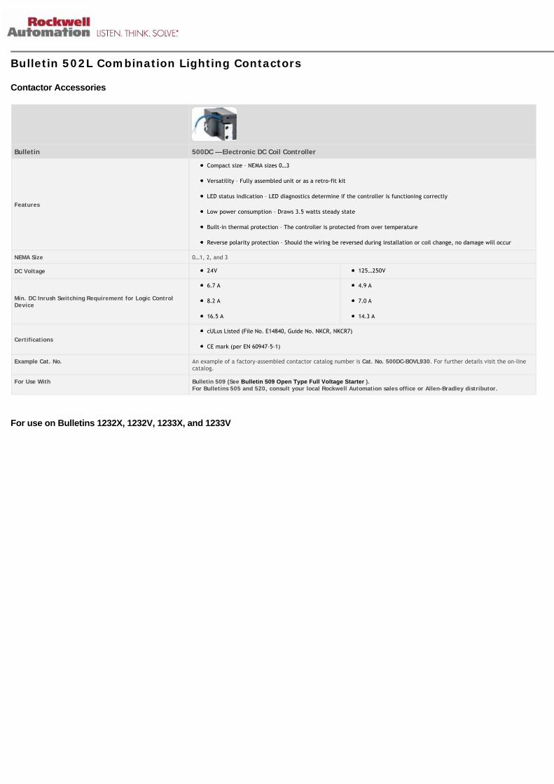
Coils (60 Hz)115…120V
0…1 CB-236
200…208V CB-249
230…240V CB-254
460…480V CB-273
575…600V CB-278
115…120V 2 CC-236
200…208V CC-249
230…240V CC-254
460…480V CC-273
575…600V CC-278
115…120V 3 CD-236
200…208V CD-249
230…240V CD-254
460…480V CD-273
575…600V CD-278
115…120V 4 CE-236
200…208V CE-249
230…240V CE-254
460…480V CE-273
575…600V CE-278
115…120V 5(SER. L)
AF-236
200…208V AF-249
230…240V AF-254
Note: For complete listing of coils available, see Bulletin 500 Line of Contactors and Starters (excluding Modular Kits) 460…480V AF-273
575…600V 5 AF-278
Surge Suppressor — Made to be easily mounted directly across the coil terminals of contactors and starters with 120V or 240V AC coils. The purpose of the suppressor is to limit voltagetransients for applications requiring interface with solid-state components. One suppressor is required per coil.
RC ModuleAC OperatingMechanism24…48V AC, 50/60 Hz
00⋆ 100-FSC48
110…280V AC, 50/60 Hz 100-FSC280
380…480V AC, 50/60 Hz 100-FSC480
Varistor ModuleAC/DC OperatingMechanism12…55V AC/ 12…77V DC
00⋆ 100-FSV55
Cat. No. 100-FSC280 56…136V AC/ 78…180V DC 100-FSV136
137…277V AC/ 181…350V DC 100-FSV277
278…575V AC 100-FSV575
12…120V AC 0…5 599-K04
240…264V AC Varistor 599-KA04
12…120V AC 6 199-FSMA1‡
12…120V ACVaristor
199-GSMA1§
Cat. No. 599-K04 120V AC 7…8 700-N24
⋆ For non-combination starters only.
‡ For use on the interposing relay.
§ For use on the contactor or starter.
Description NEMA Size Cat. No.
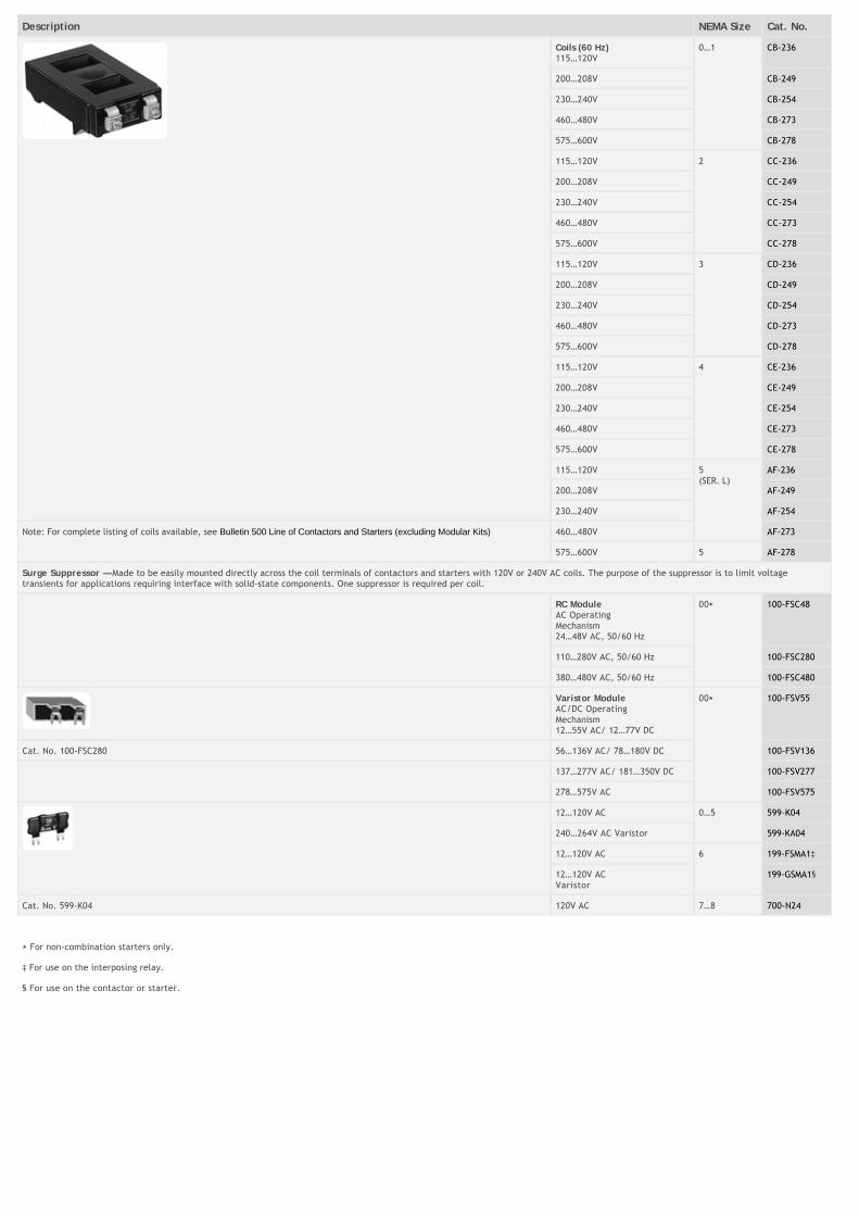
Terminal and Lug Covers
Line side terminal covers
0…1 599-TC01N
2 599-TC2N
3 599-TC3N
4 599-TC4N
5 599-TC5N
Line side terminal covers (reversing) 0…1 599-TC01R
Tie Point Terminal 0…2 599-TP02
3…5 599-TP34
Description For Use With No. of Poles NEMA Size Cat. No.
Protective Covers 500/F/FL, 500L, 500LP, 505 3 0…1 599-PC01
509, 505, 520E (2), 520F/G 3 0…1 599-PS01
500L, 500LP 5 0…1 599-PC01-5
520F/G 5 0…1 599-PS01-5
500/F/FL, 500L, 500LP, 505 3 2 599-PC2
509, 505, 520E (2), 520F/G 3 2 599-PS2
500L, 500LP 5 2 599-PC2-5
520F/G 5 2 599-PS2-5
500/F/FL, 500L, 500LP, 505 3 3 599-PC3
509, 505, 520E (2), 520F/G 3 3 599-PS3
500L, 500LP 5 3 599-PC3-5
520F/G 5 3 599-PS3-5
500/F/FL, 500L, 500LP, 505 3 4 599-PC4
509, 505, 520E (2), 520F/G 3 4 599-PS4
500L, 500LP 5 4 599-PC4-5
520F/G 5 4 599-PS4-5
500/F/FL, 500L, 500LP 3 5 599-PC5
Cat. No. 599�PS01 509 3 5 599-PS5
Used on 5-pole contactors and starters.
Bul. 592 Eutectic alloy or solid-state overload relays.
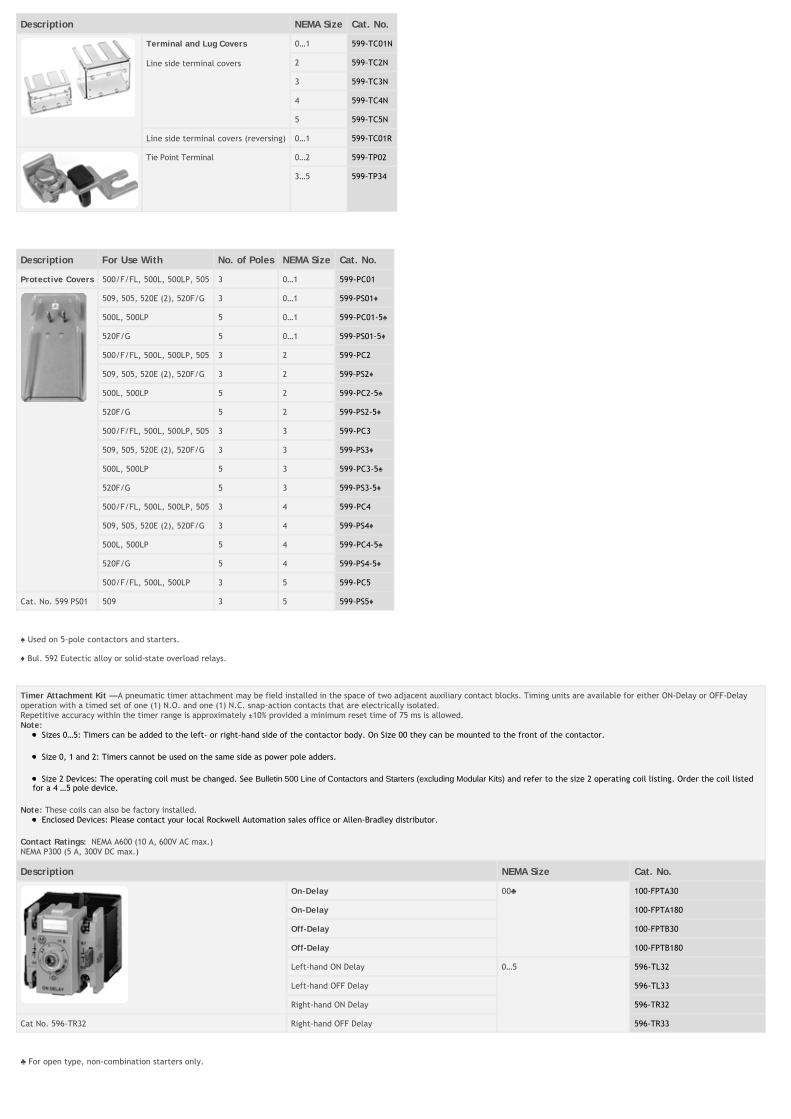
Timer Attachment Kit — A pneumatic timer attachment may be field installed in the space of two adjacent auxiliary contact blocks. Timing units are available for either ON-Delay or OFF-Delayoperation with a timed set of one (1) N.O. and one (1) N.C. snap-action contacts that are electrically isolated.Repetitive accuracy within the timer range is approximately ±10% provided a minimum reset time of 75 ms is allowed.Note:
Sizes 0…5: Timers can be added to the left- or right-hand side of the contactor body. On Size 00 they can be mounted to the front of the contactor.
Size 0, 1 and 2: Timers cannot be used on the same side as power pole adders.
Size 2 Devices: The operating coil must be changed. See Bulletin 500 Line of Contactors and Starters (excluding Modular Kits) and refer to the size 2 operating coil listing. Order the coil listedfor a 4�…5�pole device.
Note: These coils can also be factory installed.Enclosed Devices: Please contact your local Rockwell Automation sales office or Allen-Bradley distributor.
Contact Ratings: NEMA A600 (10 A, 600V AC max.)NEMA P300 (5 A, 300V DC max.)
Description NEMA Size Cat. No.
On-Delay 00 100-FPTA30
On-Delay 100-FPTA180
Off-Delay 100-FPTB30
Off-Delay 100-FPTB180
Left-hand ON Delay 0…5 596-TL32
Left-hand OFF Delay 596-TL33
Right-hand ON Delay 596-TR32
Cat No. 596-TR32 Right-hand OFF Delay 596-TR33
For open type, non-combination starters only.
Description NEMA Size Cat. No.
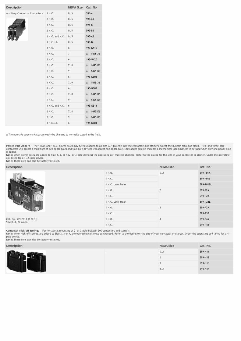
Auxiliary Contact — Contactors 1 N.O. 0…5 595-A
2 N.O. 0…5 595-AA
1 N.C. 0…5 595-B
2 N.C. 0…5 595-BB
1 N.O. and N.C. 0…5 595-AB
1 N.C.L.B. 0…5 595-BL
1 N.O. 6 195-GA10
1 N.O. 7 ∆ 1495-J6
2 N.O. 6 195-GA20
2 N.O. 7…8 ∆ 1495-K6
2 N.O. 9 ∆ 1495-K8
1 N.C. 6 195-GB01
1 N.C. 7…9 ∆ 1495-J6
2 N.C. 6 195-GB02
2 N.C. 7…8 ∆ 1495-K6
2 N.C. 9 ∆ 1495-K8
1 N.O. and N.C. 6 195-GB11
2 N.O. 7…8 ∆ 1495-K6
2 N.O. 9 ∆ 1495-K8
1 N.C.L.B. 6 195-GL01
∆ The normally open contacts can easily be changed to normally closed in the field.
Power Pole Adders — The 1 N.O. and 1 N.C. power poles may be field added to all size 0…4 Bulletin 500 line contactors and starters except the Bulletin 500L and 500FL. Two- and three-polecontactors will accept a maximum of two adder poles and four-pole devices will accept one adder pole. Each adder pole kit includes a mechanical load balancer to be used when only one power poleis added. Note: When power poles are added to Size 2, 3, or 4 (2- or 3-pole devices) the operating coil must be changed. Refer to the listing for the size of your contactor or starter. Order the operatingcoil listed for a 4-…5-pole device.Note: These coils can also be factory installed.
Description NEMA Size Cat. No.
1 N.O. 0…1 599-P01A
1 N.C. 599-P01B
1 N.C. Late Break 599-P01BL
1 N.O. 2 599-P2A
1 N.C. 599-P2B
1 N.C. Late Break 599-P2BL
1 N.O. 3 599-P3A
1 N.C. 599-P3B
Cat. No. 599-P01A (1 N.O.)Size 0…1, 27 Amps.
1 N.O. 4 599-P4A
1 N.C. 599-P4B
Contactor Kick-off Springs — For horizontal mounting of 2- or 3-pole Bulletin 500 contactors and starters.Note: When kick-off springs are added to Size 2, 3 or 4, the operating coil must be changed. Refer to the listing for the size of your contactor or starter. Order the operating coil listed for a 4-pole device.Note: These coils can also be factory installed.
Description NEMA Size Cat. No.
— 0…1 599-N11
2 599-N12
3 599-N13
4…5 599-N14
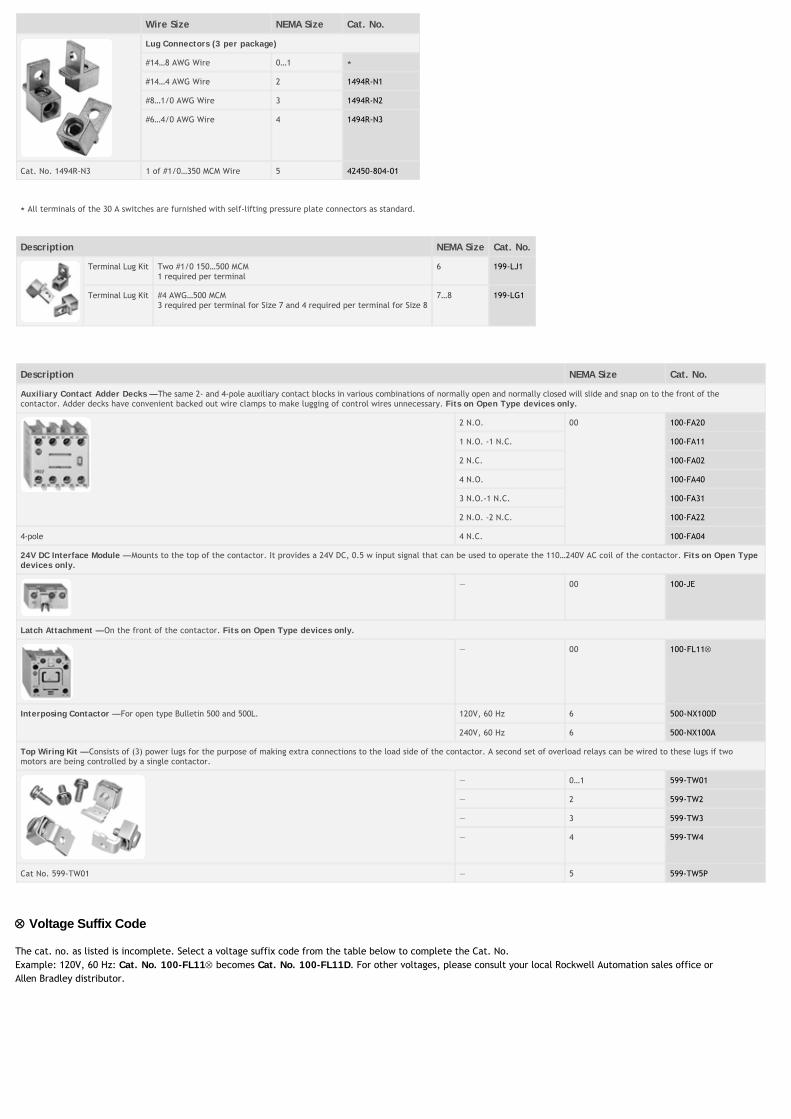
Wire Size NEMA Size Cat. No.
Lug Connectors (3 per package)
#14…8 AWG Wire 0…1 ⋆
#14…4 AWG Wire 2 1494R-N1
#8…1/0 AWG Wire 3 1494R-N2
#6…4/0 AWG Wire 4 1494R-N3
Cat. No. 1494R-N3 1 of #1/0…350 MCM Wire 5 42450-804-01
⋆ All terminals of the 30 A switches are furnished with self-lifting pressure plate connectors as standard.
Description NEMA Size Cat. No.
Terminal Lug Kit Two #1/0 150…500 MCM1 required per terminal
6 199-LJ1
Terminal Lug Kit #4 AWG…500 MCM3 required per terminal for Size 7 and 4 required per terminal for Size 8
7…8 199-LG1
Description NEMA Size Cat. No.
Auxiliary Contact Adder Decks — The same 2- and 4-pole auxiliary contact blocks in various combinations of normally open and normally closed will slide and snap on to the front of thecontactor. Adder decks have convenient backed out wire clamps to make lugging of control wires unnecessary. Fits on Open Type devices only.
2 N.O. 00 100-FA20
1 N.O. -1 N.C. 100-FA11
2 N.C. 100-FA02
4 N.O. 100-FA40
3 N.O.-1 N.C. 100-FA31
2 N.O. -2 N.C. 100-FA22
4-pole 4 N.C. 100-FA04
24V DC Interface Module — Mounts to the top of the contactor. It provides a 24V DC, 0.5 w input signal that can be used to operate the 110…240V AC coil of the contactor. Fits on Open Typedevices only.
— 00 100-JE
Latch Attachment — On the front of the contactor. Fits on Open Type devices only.
— 00 100-FL11
Interposing Contactor — For open type Bulletin 500 and 500L. 120V, 60 Hz 6 500-NX100D
240V, 60 Hz 6 500-NX100A
Top Wiring Kit — Consists of (3) power lugs for the purpose of making extra connections to the load side of the contactor. A second set of overload relays can be wired to these lugs if twomotors are being controlled by a single contactor.
— 0…1 599-TW01
— 2 599-TW2
— 3 599-TW3
— 4 599-TW4
Cat No. 599-TW01 — 5 599-TW5P
Voltage Suffix Code
The cat. no. as listed is incomplete. Select a voltage suffix code from the table below to complete the Cat. No.Example: 120V, 60 Hz: Cat. No. 100-FL11 becomes Cat. No. 100-FL11D. For other voltages, please consult your local Rockwell Automation sales office orAllen�Bradley distributor.
[V] 24 48 100 110 120 230…240
240 277 380…400
400…415
400 480
50 Hz K Y KP D — VA T — N G B —
60 Hz J — — — D — A T — — N B
§ To complete cat. no., insert in the third position the desired numeric symbol (0…5) or one of the following letters — A, B, C, D, E, F, H, L, M, P, R, S, T, U, or W.
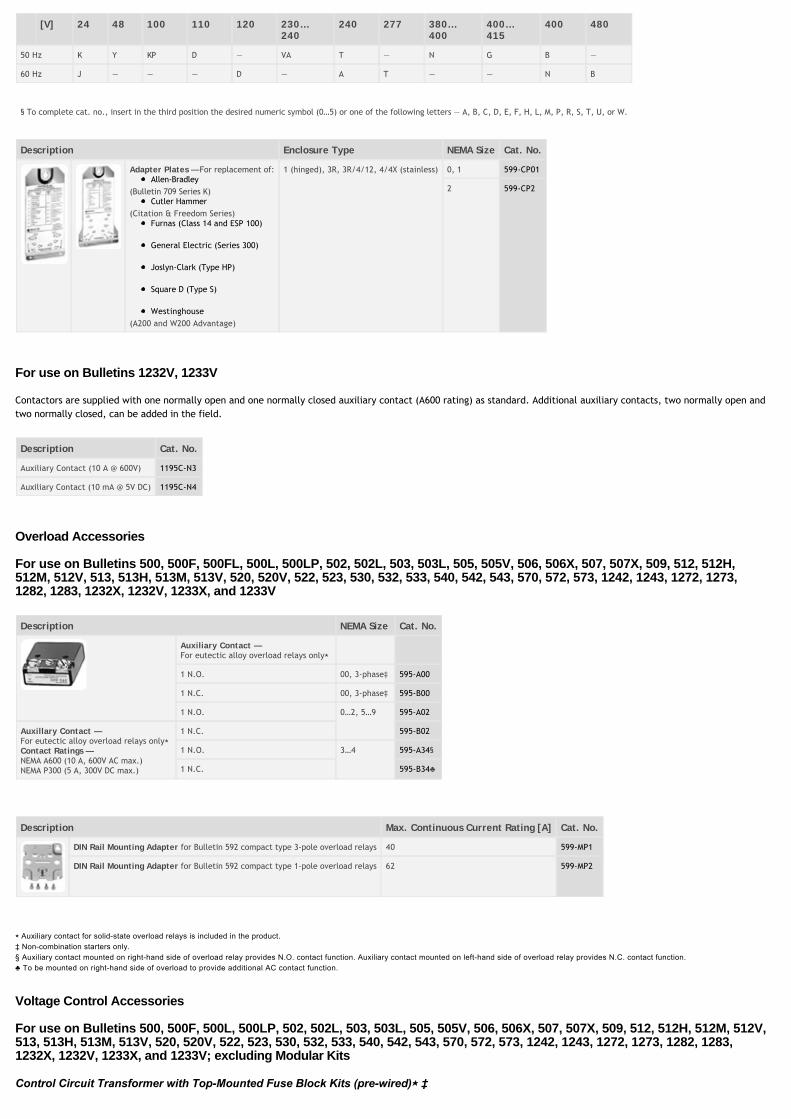
Description Enclosure Type NEMA Size Cat. No.
Adapter Plates — For replacement of:Allen-Bradley
(Bulletin 709 Series K)Cutler Hammer
(Citation & Freedom Series)Furnas (Class 14 and ESP 100)
General Electric (Series 300)
Joslyn-Clark (Type HP)
Square D (Type S)
Westinghouse(A200 and W200 Advantage)
1 (hinged), 3R, 3R/4/12, 4/4X (stainless) 0, 1 599-CP01
2 599-CP2
For use on Bulletins 1232V, 1233V
Contactors are supplied with one normally open and one normally closed auxiliary contact (A600 rating) as standard. Additional auxiliary contacts, two normally open andtwo normally closed, can be added in the field.
Description Cat. No.
Auxiliary Contact (10 A @ 600V) 1195C-N3
Auxiliary Contact (10 mA @ 5V DC) 1195C-N4
Overload Accessories
For use on Bulletins 500, 500F, 500FL, 500L, 500LP, 502, 502L, 503, 503L, 505, 505V, 506, 506X, 507, 507X, 509, 512, 512H,512M, 512V, 513, 513H, 513M, 513V, 520, 520V, 522, 523, 530, 532, 533, 540, 542, 543, 570, 572, 573, 1242, 1243, 1272, 1273,1282, 1283, 1232X, 1232V, 1233X, and 1233V
Description NEMA Size Cat. No.
Auxiliary Contact —For eutectic alloy overload relays only⋆
1 N.O. 00, 3-phase‡ 595-A00
1 N.C. 00, 3-phase‡ 595-B00
1 N.O. 0…2, 5…9 595-A02
Auxillary Contact —For eutectic alloy overload relays only⋆ Contact Ratings —NEMA A600 (10 A, 600V AC max.)NEMA P300 (5 A, 300V DC max.)
1 N.C. 595-B02
1 N.O. 3…4 595-A34§
1 N.C. 595-B34
Description Max. Continuous Current Rating [A] Cat. No.
DIN Rail Mounting Adapter for Bulletin 592 compact type 3-pole overload relays 40 599-MP1
DIN Rail Mounting Adapter for Bulletin 592 compact type 1-pole overload relays 62 599-MP2
⋆
Voltage Control Accessories
For use on Bulletins 500, 500F, 500L, 500LP, 502, 502L, 503, 503L, 505, 505V, 506, 506X, 507, 507X, 509, 512, 512H, 512M, 512V,513, 513H, 513M, 513V, 520, 520V, 522, 523, 530, 532, 533, 540, 542, 543, 570, 572, 573, 1242, 1243, 1272, 1273, 1282, 1283,1232X, 1232V, 1233X, and 1233V; excluding Modular Kits
⋆
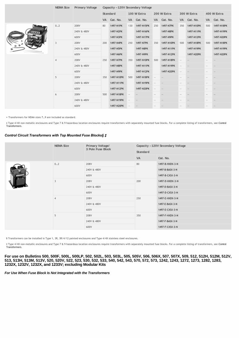
NEMA Size Primary Voltage Capacity – 120V Secondary Voltage
Standard 100 W Extra 200 W Extra 300 W Extra 400 W Extra
VA Cat. No. VA Cat. No. VA Cat. No. VA Cat. No. VA Cat. No.
0…2 208V 80 1497-N1PK 130 1497-N15PK 250 1497-N7PK 350 1497-N10PK 500 1497-N18PK
240V & 480V 1497-N2PK 1497-N16PK 1497-N8PK 1497-N11PK 1497-N19PK
600V 1497-N3PK 1497-N17PK 1497-N9PK 1497-N12PK 1497-N20PK
3 208V 200 1497-N4PK 250 1497-N7PK 350 1497-N10PK 500 1497-N18PK 500 1497-N18PK
240V & 480V 1497-N5PK 1497-N8PK 1497-N11PK 1497-N19PK 1497-N19PK
600V 1497-N6PK 1497-N9PK 1497-N12PK 1497-N20PK 1497-N20PK
4 208V 250 1497-N7PK 350 1497-N10PK 500 1497-N18PK — — — —
240V & 480V 1497-N8PK 1497-N11PK 1497-N19PK — — — —
600V 1497-N9PK 1497-N12PK 1497-N20PK — — — —
5 208V 350 1497-N10PK 500 1497-N18PK — — — — — —
240V & 480V 1497-N11PK 1497-N19PK — — — — — —
600V 1497-N12PK 1497-N20PK — — — — — —
6 208V 500 1497-N18PK — — — — — — — —
240V & 480V 1497-N19PK — — — — — — — —
600V 1497-N20PK — — — — — — — —
⋆ Transformers for NEMA sizes 7…9 are included as standard.
‡ Type 4/4X non-metallic enclosures and Type 7 & 9 hazardous location enclosures require transformers with separately mounted fuse blocks. For a complete listing of transformers, see ControlTransformers.
NEMA Size Primary Voltage/3 Pole Fuse Block
Capacity – 120V Secondary Voltage
Standard
VA Cat. No.
0…2 208V 80 1497-B-HXDX-3-N
240V & 480V 1497-B-BASX-3-N
600V 1497-B-CXSX-3-N
3 208V 200 1497-D-HXDX-3-N
240V & 480V 1497-D-BASX-3-N
600V 1497-D-CXSX-3-N
4 208V 250 1497-E-HXDX-3-N
240V & 480V 1497-E-BASX-3-N
600V 1497-E-CXSX-3-N
5 208V 350 1497-F-HXDX-3-N
240V & 480V 1497-F-BASX-3-N
600V 1497-F-CXSX-3-N
§ Transformers can be installed in Type 1, 3R, 3R/4/12 painted enclosures and Type 4/4X stainless steel enclosures.
‡ Type 4/4X non-metallic enclosures and Type 7 & 9 hazardous location enclosures require transformers with separately mounted fuse blocks. For a complete listing of transformers, see ControlTransformers.
For use on Bulletins 500, 500F, 500L, 500LP, 502, 502L, 503, 503L, 505, 505V, 506, 506X, 507, 507X, 509, 512, 512H, 512M, 512V,513, 513H, 513M, 513V, 520, 520V, 522, 523, 530, 532, 533, 540, 542, 543, 570, 572, 573, 1242, 1243, 1272, 1273, 1282, 1283,1232X, 1232V, 1232X, and 1233V; excluding Modular Kits
For Use When Fuse Block Is Not Integrated with the Transformers
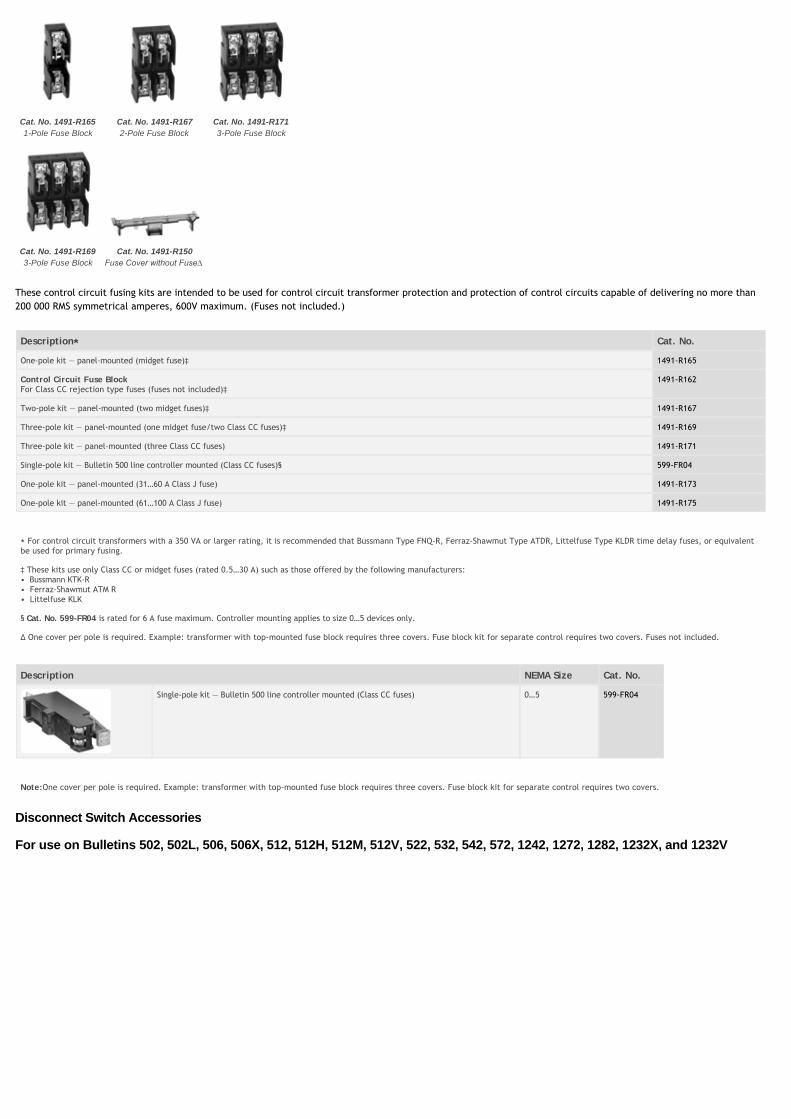
Cat. No. 1491-R1651-Pole Fuse Block
Cat. No. 1491-R1672-Pole Fuse Block
Cat. No. 1491-R1713-Pole Fuse Block
Cat. No. 1491-R1693-Pole Fuse Block
Cat. No. 1491-R150
These control circuit fusing kits are intended to be used for control circuit transformer protection and protection of control circuits capable of delivering no more than200 000 RMS symmetrical amperes, 600V maximum. (Fuses not included.)
Description⋆⋆ Cat. No.
One-pole kit — panel-mounted (midget fuse)‡ 1491-R165
Control Circuit Fuse BlockFor Class CC rejection type fuses (fuses not included)‡
1491-R162
Two-pole kit — panel-mounted (two midget fuses)‡ 1491-R167
Three-pole kit — panel-mounted (one midget fuse/two Class CC fuses)‡ 1491-R169
Three-pole kit — panel-mounted (three Class CC fuses) 1491-R171
Single-pole kit — Bulletin 500 line controller mounted (Class CC fuses)§ 599-FR04
One-pole kit — panel-mounted (31…60 A Class J fuse) 1491-R173
One-pole kit — panel-mounted (61…100 A Class J fuse) 1491-R175
⋆ For control circuit transformers with a 350 VA or larger rating, it is recommended that Bussmann Type FNQ-R, Ferraz-Shawmut Type ATDR, Littelfuse Type KLDR time delay fuses, or equivalentbe used for primary fusing.
‡ These kits use only Class CC or midget fuses (rated 0.5…30 A) such as those offered by the following manufacturers:• Bussmann KTK-R• Ferraz-Shawmut ATM R• Littelfuse KLK
§ Cat. No. 599-FR04 is rated for 6 A fuse maximum. Controller mounting applies to size 0…5 devices only.
∆ One cover per pole is required. Example: transformer with top-mounted fuse block requires three covers. Fuse block kit for separate control requires two covers. Fuses not included.
Description NEMA Size Cat. No.
Single-pole kit — Bulletin 500 line controller mounted (Class CC fuses) 0…5 599-FR04
Note:One cover per pole is required. Example: transformer with top-mounted fuse block requires three covers. Fuse block kit for separate control requires two covers.
Disconnect Switch Accessories
For use on Bulletins 502, 502L, 506, 506X, 512, 512H, 512M, 512V, 522, 532, 542, 572, 1242, 1272, 1282, 1232X, and 1232V
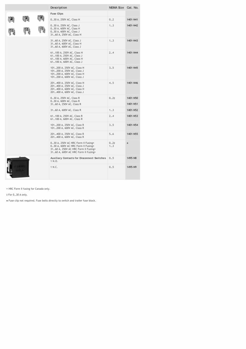
Description NEMA Size Cat. No.
Fuse Clips
0…30 A, 250V AC, Class H 0…2 1401-N41
0…30 A, 250V AC, Class J0…30 A, 600V AC, Class H0…30 A, 600V AC, Class J31…60 A, 250V AC, Class H
1…3 1401-N42
31…60 A, 250V AC, Class J31…60 A, 600V AC, Class H31…60 A, 600V AC, Class J
1…3 1401-N43
61…100 A, 250V AC, Class H61…100 A, 250V AC, Class J61…100 A, 600V AC, Class H61…100 A, 600V AC, Class J
2…4 1401-N44
101…200 A, 250V AC, Class H101…200 A, 250V AC, Class J101…200 A, 600V AC, Class H101…200 A, 600V AC, Class J
3…5 1401-N45
201…400 A, 250V AC, Class H201…400 A, 250V AC, Class J201…400 A, 600V AC, Class H201…400 A, 600V AC, Class J
4…5 1401-N46
0…30 A, 250V AC, Class R0…30 A, 600V AC, Class R31…60 A, 250V AC, Class R
0…2‡ 1401-N50
1401-N51
31…60 A, 600V AC, Class R 1…3 1401-N52
61…100 A, 250V AC, Class R61…100 A, 600V AC, Class R
2…4 1401-N53
101…200 A, 250V AC, Class R101…200 A, 600V AC, Class R
3…5 1401-N54
201…400 A, 250V AC, Class R201…400 A, 600V AC, Class R
5…6 1401-N55
0…30 A, 250V AC HRC Form II Fusing⋆ 0…30 A, 600V AC HRC Form II Fusing⋆ 31…60 A, 250V AC HRC Form II Fusing⋆ 31…60 A, 600V AC HRC Form II Fusing⋆
0…2‡ 1…3
Auxiliary Contacts for Disconnect Switches1 N.O.
0…5 1495-N8
1 N.C. 0…5 1495-N9
⋆ HRC Form II fusing for Canada only.
‡ For 0…30 A only.
Fuse clip not required. Fuse bolts directly to switch and trailer fuse block.
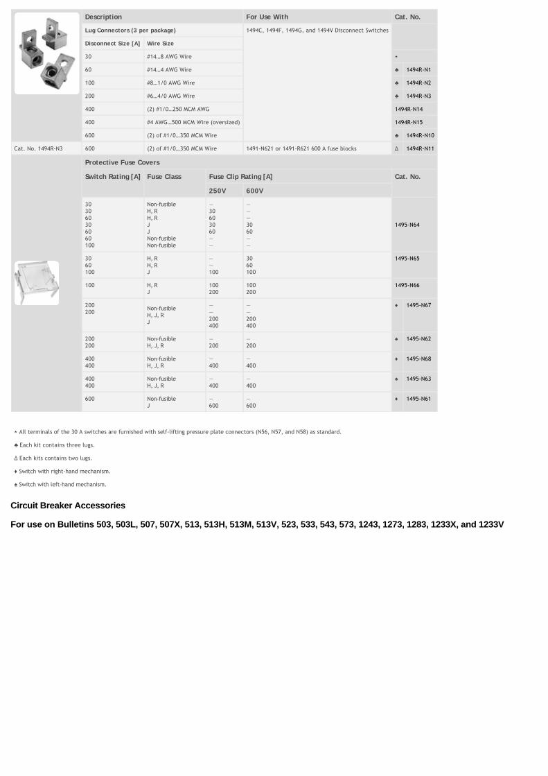
Description For Use With Cat. No.
Lug Connectors (3 per package) 1494C, 1494F, 1494G, and 1494V Disconnect Switches
Disconnect Size [A] Wire Size
30 #14…8 AWG Wire ⋆
60 #14…4 AWG Wire 1494R-N1
100 #8…1/0 AWG Wire 1494R-N2
200 #6…4/0 AWG Wire 1494R-N3
400 (2) #1/0…250 MCM AWG 1494R-N14
400 #4 AWG…500 MCM Wire (oversized) 1494R-N15
600 (2) of #1/0…350 MCM Wire 1494R-N10
Cat. No. 1494R-N3 600 (2) of #1/0…350 MCM Wire 1491-N621 or 1491-R621 600 A fuse blocks ∆ 1494R-N11
Protective Fuse Covers
Switch Rating [A] Fuse Class Fuse Clip Rating [A] Cat. No.
250V 600V
303060306060100
Non-fusibleH, RH, RJJNon-fusibleNon-fusible
—30603060——
———3060——
1495-N64
3060100
H, RH, RJ
——100
3060100
1495-N65
100 H, RJ
100200
100200
1495-N66
200200
Non-fusibleH, J, RJ
——200400
——200400
1495-N67
200200
Non-fusibleH, J, R
—200
—200
1495-N62
400400
Non-fusibleH, J, R
—400
—400
1495-N68
400400
Non-fusibleH, J, R
—400
—400
1495-N63
600 Non-fusibleJ
—600
—600
1495-N61
⋆ All terminals of the 30 A switches are furnished with self-lifting pressure plate connectors (N56, N57, and N58) as standard.
Each kit contains three lugs.
∆ Each kits contains two lugs.
Switch with right-hand mechanism.
Switch with left-hand mechanism.
Circuit Breaker Accessories
For use on Bulletins 503, 503L, 507, 507X, 513, 513H, 513M, 513V, 523, 533, 543, 573, 1243, 1273, 1283, 1233X, and 1233V
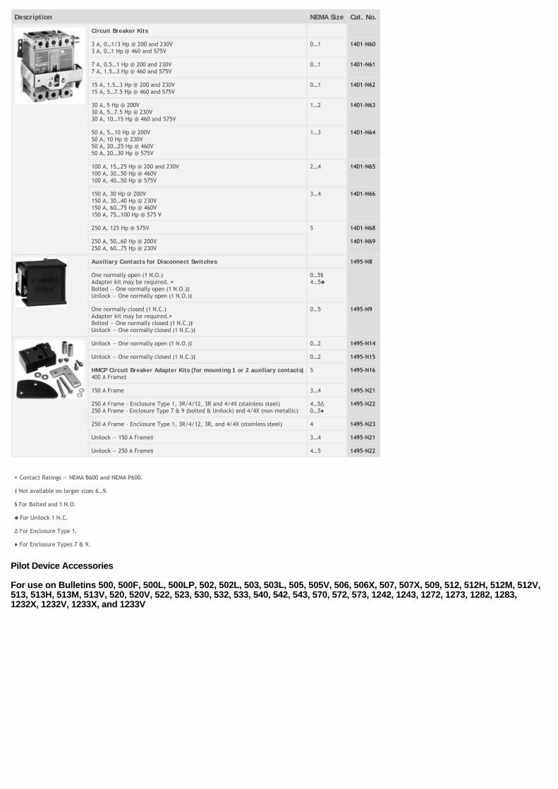
Description NEMA Size Cat. No.
Circuit Breaker Kits
3 A, 0…1/3 Hp @ 200 and 230V3 A, 0…1 Hp @ 460 and 575V
0…1 1401-N60
7 A, 0.5…1 Hp @ 200 and 230V7 A, 1.5…3 Hp @ 460 and 575V
0…1 1401-N61
15 A, 1.5…3 Hp @ 200 and 230V15 A, 5…7.5 Hp @ 460 and 575V
0…1 1401-N62
30 A, 5 Hp @ 200V30 A, 5…7.5 Hp @ 230V30 A, 10…15 Hp @ 460 and 575V
1…2 1401-N63
50 A, 5…10 Hp @ 200V50 A, 10 Hp @ 230V50 A, 20…25 Hp @ 460V50 A, 20…30 Hp @ 575V
1…3 1401-N64
100 A, 15…25 Hp @ 200 and 230V100 A, 30…50 Hp @ 460V100 A, 40…50 Hp @ 575V
2…4 1401-N65
150 A, 30 Hp @ 200V150 A, 30…40 Hp @ 230V150 A, 60…75 Hp @ 460V150 A, 75…100 Hp @ 575 V
3…4 1401-N66
250 A, 125 Hp @ 575V 5 1401-N68
250 A, 50…60 Hp @ 200V250 A, 60…75 Hp @ 230V
1401-N69
Auxiliary Contacts for Disconnect Switches 1495-N8
One normally open (1 N.O.)Adapter kit may be required. ⋆ Bolted — One normally open (1 N.O.)‡ Unilock — One normally open (1 N.O.)‡
0…5§ 4…5
One normally closed (1 N.C.)Adapter kit may be required.⋆ Bolted — One normally closed (1 N.C.)‡ Unilock — One normally closed (1 N.C.)‡
0…5 1495-N9
Unilock — One normally open (1 N.O.)‡ 0…2 1495-N14
Unilock — One normally closed (1 N.C.)‡ 0…2 1495-N15
HMCP Circuit Breaker Adapter Kits (for mounting 1 or 2 auxiliary contacts)400 A Frame‡
5 1495-N16
150 A Frame 3…4 1495-N21
250 A Frame - Enclosure Type 1, 3R/4/12, 3R and 4/4X (stainless steel)250 A Frame - Enclosure Type 7 & 9 (bolted & Unilock) and 4/4X (non-metallic)
4…5∆ 0…5
1495-N22
250 A Frame - Enclosure Type 1, 3R/4/12, 3R, and 4/4X (stainless steel) 4 1495-N23
Unilock — 150 A Frame‡ 3…4 1495-N21
Unilock — 250 A Frame‡ 4…5 1495-N22
⋆ Contact Ratings — NEMA B600 and NEMA P600.
‡ Not available on larger sizes 6…9.
§ For Bolted and 1 N.O.
For Unilock 1 N.C.
∆ For Enclosure Type 1.
For Enclosure Types 7 & 9.
Pilot Device Accessories
For use on Bulletins 500, 500F, 500L, 500LP, 502, 502L, 503, 503L, 505, 505V, 506, 506X, 507, 507X, 509, 512, 512H, 512M, 512V,513, 513H, 513M, 513V, 520, 520V, 522, 523, 530, 532, 533, 540, 542, 543, 570, 572, 573, 1242, 1243, 1272, 1273, 1282, 1283,1232X, 1232V, 1233X, and 1233V
Description Enclosure Type NEMA Size Cat. No.
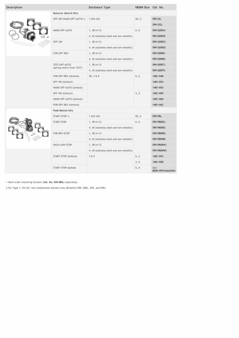
Selector Switch Kits
OFF-ON/HAND-OFF-AUTO⋆ ‡ 1 (lift-off) 00…2 599-SSL
599-SS2L
HAND-OFF-AUTO 1, 3R/4/12 0…5 599-SS09HJ
4, 4X (stainless steel and non-metallic) 599-SS09HS
OFF-ON 1, 3R/4/12 599-SS09OJ
4, 4X (stainless steel and non-metallic) 599-SS09OS
FOR-OFF-REV 1, 3R/4/12 599-SS09RJ
4, 4X (stainless steel and non-metallic) 599-SS09RS
TEST-OFF-AUTO(spring return from TEST)
1, 3R/4/12 599-SS09TJ
4, 4X (stainless steel and non-metallic) 599-SS09TS
FOR-OFF-REV (Unilock) 3R, 7 & 9 0…2 1481-N48
OFF-ON (Unilock) 1481-N54
HAND-OFF-AUTO (Unilock) 1481-N55
OFF-ON (Unilock) 3…5 1481-N59
HAND-OFF-AUTO (Unilock) 1481-N60
FOR-OFF-REV (Unilock) 1481-N62
Push Button Kits
START-STOP⋆ ‡ 1 (lift-off) 00…2 599-PBL
START-STOP 1, 3R/4/12 0…5 599-PB09SJ
4, 4X (stainless steel and non-metallic) 599-PB09SS
FOR-REV-STOP 1, 3R/4/12 599-PB09RJ
4, 4X (stainless steel and non-metallic) 599-PB09RS
HIGH-LOW-STOP 1, 3R/4/12 599-PB09WJ
4, 4X (stainless steel and non-metallic) 599-PB09WS
START-STOP (Unilock) 7 & 9 0…2 1481-N53
3…5 1481-N58
START-STOP (bolted) 0…9 Use800H-DPH16AAXX64
⋆ Must order mounting bracket (Cat. No. 599-BRL) separately.
‡ For Type 1, lift-off, non-combination starters only (Bulletins 500, 500L, 505, and 509).
Description Enclosure Type NEMA Size Cat. No.
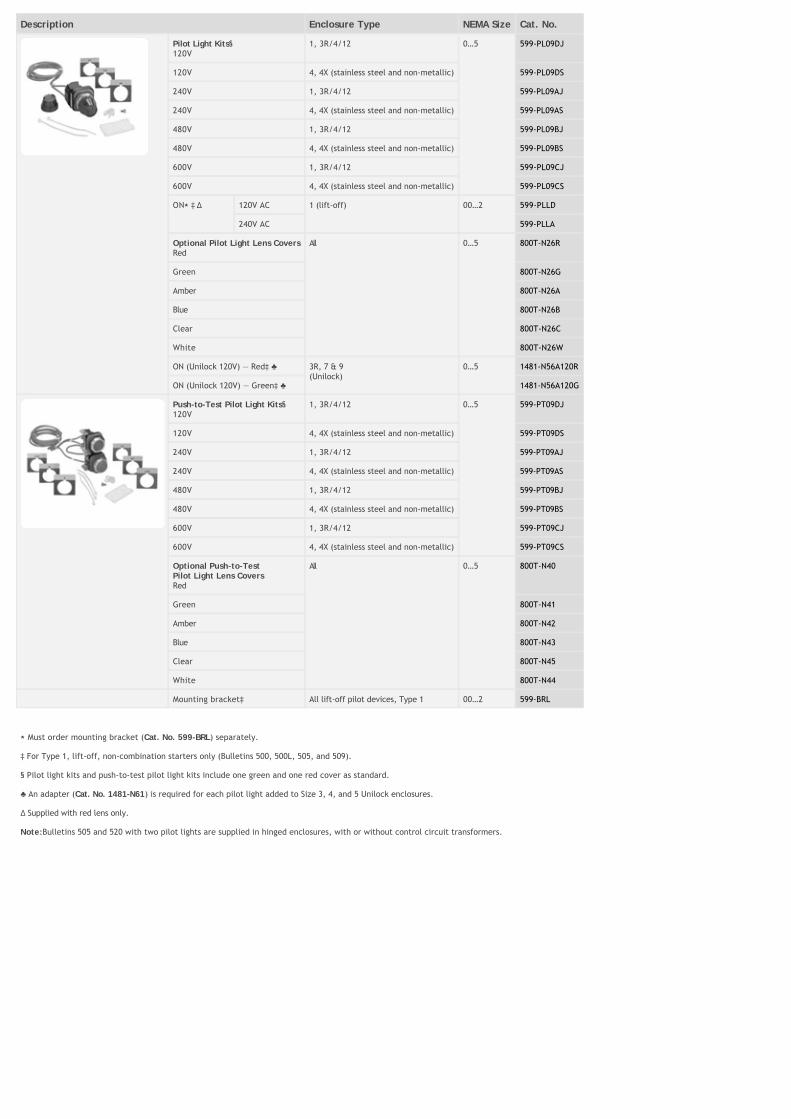
Pilot Light Kits§ 120V
1, 3R/4/12 0…5 599-PL09DJ
120V 4, 4X (stainless steel and non-metallic) 599-PL09DS
240V 1, 3R/4/12 599-PL09AJ
240V 4, 4X (stainless steel and non-metallic) 599-PL09AS
480V 1, 3R/4/12 599-PL09BJ
480V 4, 4X (stainless steel and non-metallic) 599-PL09BS
600V 1, 3R/4/12 599-PL09CJ
600V 4, 4X (stainless steel and non-metallic) 599-PL09CS
ON⋆ ‡ ∆ 120V AC 1 (lift-off) 00…2 599-PLLD
240V AC 599-PLLA
Optional Pilot Light Lens CoversRed
All 0…5 800T-N26R
Green 800T-N26G
Amber 800T-N26A
Blue 800T-N26B
Clear 800T-N26C
White 800T-N26W
ON (Unilock 120V) — Red‡ 3R, 7 & 9(Unilock)
0…5 1481-N56A120R
ON (Unilock 120V) — Green‡ 1481-N56A120G
Push-to-Test Pilot Light Kits§ 120V
1, 3R/4/12 0…5 599-PT09DJ
120V 4, 4X (stainless steel and non-metallic) 599-PT09DS
240V 1, 3R/4/12 599-PT09AJ
240V 4, 4X (stainless steel and non-metallic) 599-PT09AS
480V 1, 3R/4/12 599-PT09BJ
480V 4, 4X (stainless steel and non-metallic) 599-PT09BS
600V 1, 3R/4/12 599-PT09CJ
600V 4, 4X (stainless steel and non-metallic) 599-PT09CS
Optional Push-to-TestPilot Light Lens CoversRed
All 0…5 800T-N40
Green 800T-N41
Amber 800T-N42
Blue 800T-N43
Clear 800T-N45
White 800T-N44
Mounting bracket‡ All lift-off pilot devices, Type 1 00…2 599-BRL
⋆ Must order mounting bracket (Cat. No. 599-BRL) separately.
‡ For Type 1, lift-off, non-combination starters only (Bulletins 500, 500L, 505, and 509).
§ Pilot light kits and push-to-test pilot light kits include one green and one red cover as standard.
An adapter (Cat. No. 1481-N61) is required for each pilot light added to Size 3, 4, and 5 Unilock enclosures.
∆ Supplied with red lens only.
Note:Bulletins 505 and 520 with two pilot lights are supplied in hinged enclosures, with or without control circuit transformers.
Description Enclosure Type NEMA Size Cat. No.
ON ‡ (Unilock) —Red Lens (120V)
3R, 7 & 9(Unilock)
0…5 1481-N56A120R
ON ‡ (Unilock) —Green Lens (120V)
1481-N56A120G
Transformers for pilot lights 240V, 60 Hz and 220V, 50 Hz⋆
00…5 1481-NX1
480V, 60 Hz and 440V, 50 Hz 1481-NX2
600V, 60 Hz and 550V, 50 Hz 1481-NX3
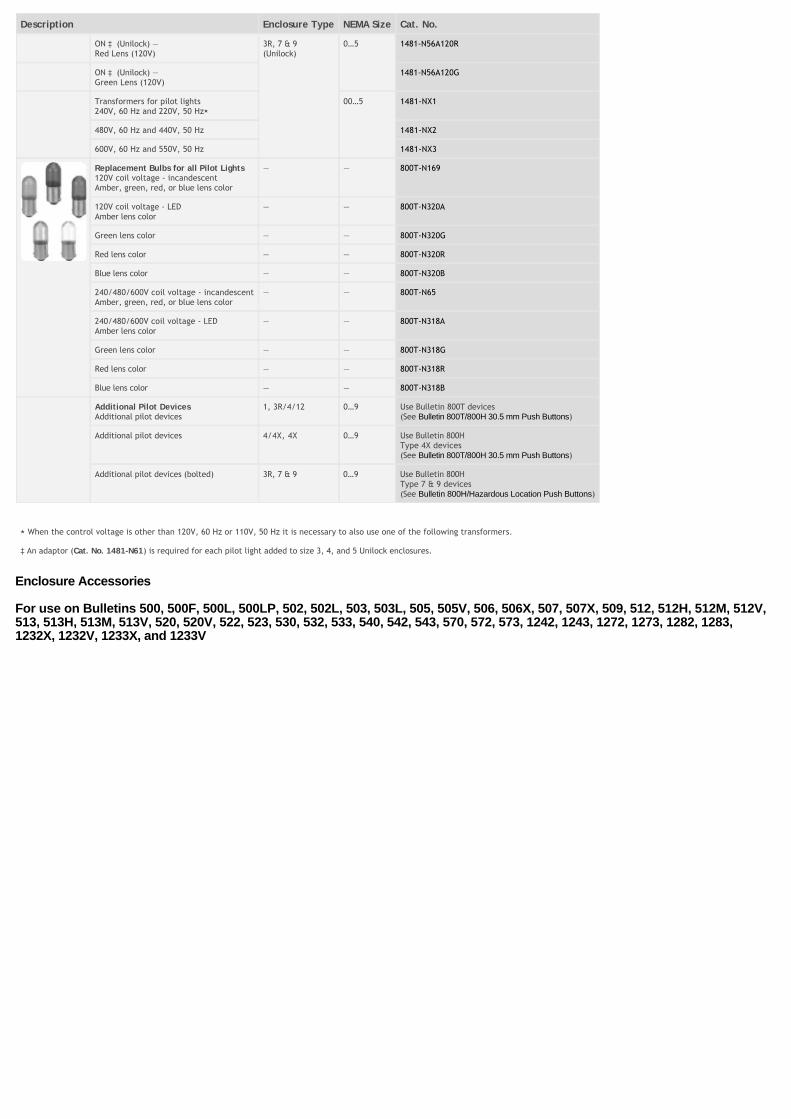
Replacement Bulbs for all Pilot Lights120V coil voltage - incandescentAmber, green, red, or blue lens color
— — 800T-N169
120V coil voltage - LEDAmber lens color
— — 800T-N320A
Green lens color — — 800T-N320G
Red lens color — — 800T-N320R
Blue lens color — — 800T-N320B
240/480/600V coil voltage - incandescentAmber, green, red, or blue lens color
— — 800T-N65
240/480/600V coil voltage - LEDAmber lens color
— — 800T-N318A
Green lens color — — 800T-N318G
Red lens color — — 800T-N318R
Blue lens color — — 800T-N318B
Additional Pilot DevicesAdditional pilot devices
1, 3R/4/12 0…9 Use Bulletin 800T devices(See Bulletin 800T/800H 30.5 mm Push Buttons)
Additional pilot devices 4/4X, 4X 0…9 Use Bulletin 800HType 4X devices(See Bulletin 800T/800H 30.5 mm Push Buttons)
Additional pilot devices (bolted) 3R, 7 & 9 0…9 Use Bulletin 800HType 7 & 9 devices(See Bulletin 800H/Hazardous Location Push Buttons)
⋆ When the control voltage is other than 120V, 60 Hz or 110V, 50 Hz it is necessary to also use one of the following transformers.
‡ An adaptor (Cat. No. 1481-N61) is required for each pilot light added to size 3, 4, and 5 Unilock enclosures.
Enclosure Accessories
For use on Bulletins 500, 500F, 500L, 500LP, 502, 502L, 503, 503L, 505, 505V, 506, 506X, 507, 507X, 509, 512, 512H, 512M, 512V,513, 513H, 513M, 513V, 520, 520V, 522, 523, 530, 532, 533, 540, 542, 543, 570, 572, 573, 1242, 1243, 1272, 1273, 1282, 1283,1232X, 1232V, 1233X, and 1233V
Description Enclosure Type NEMA Size Cat. No.
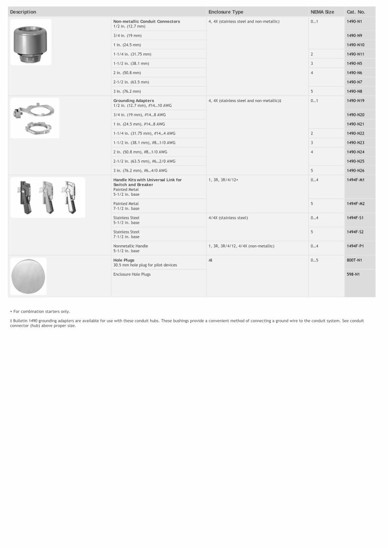
Non-metallic Conduit Connectors1/2 in. (12.7 mm)
4, 4X (stainless steel and non-metallic) 0…1 1490-N1
3/4 in. (19 mm) 1490-N9
1 in. (24.5 mm) 1490-N10
1-1/4 in. (31.75 mm) 2 1490-N11
1-1/2 in. (38.1 mm) 3 1490-N5
2 in. (50.8 mm) 4 1490-N6
2-1/2 in. (63.5 mm) 1490-N7
3 in. (76.2 mm) 5 1490-N8
Grounding Adapters1/2 in. (12.7 mm), #14…10 AWG
4, 4X (stainless steel and non-metallic)‡ 0…1 1490-N19
3/4 in. (19 mm), #14…8 AWG 1490-N20
1 in. (24.5 mm), #14…8 AWG 1490-N21
1-1/4 in. (31.75 mm), #14…4 AWG 2 1490-N22
1-1/2 in. (38.1 mm), #8…1/0 AWG 3 1490-N23
2 in. (50.8 mm), #8…1/0 AWG 4 1490-N24
2-1/2 in. (63.5 mm), #6…2/0 AWG 1490-N25
3 in. (76.2 mm), #6…4/0 AWG 5 1490-N26
Handle Kits with Universal Link forSwitch and BreakerPainted Metal5-1/2 in. base
1, 3R, 3R/4/12⋆ 0…4 1494F-M1
Painted Metal7-1/2 in. base
5 1494F-M2
Stainless Steel5-1/2 in. base
4/4X (stainless steel) 0…4 1494F-S1
Stainless Steel7-1/2 in. base
5 1494F-S2
Nonmetallic Handle5-1/2 in. base
1, 3R, 3R/4/12, 4/4X (non-metallic) 0…4 1494F-P1
Hole Plugs30.5 mm hole plug for pilot devices
All 0…5 800T-N1
Enclosure Hole Plugs 598-N1
⋆ For combination starters only.
‡ Bulletin 1490 grounding adapters are available for use with these conduit hubs. These bushings provide a convenient method of connecting a ground wire to the conduit system. See conduitconnector (hub) above proper size.
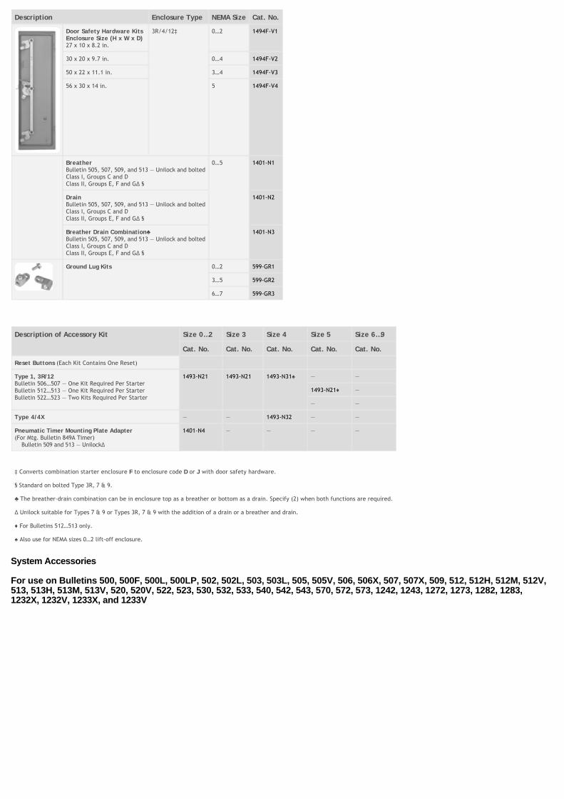
Description Enclosure Type NEMA Size Cat. No.
Door Safety Hardware KitsEnclosure Size (H x W x D)27 x 10 x 8.2 in.
3R/4/12‡ 0…2 1494F-V1
30 x 20 x 9.7 in. 0…4 1494F-V2
50 x 22 x 11.1 in. 3…4 1494F-V3
56 x 30 x 14 in. 5 1494F-V4
BreatherBulletin 505, 507, 509, and 513 — Unilock and boltedClass I, Groups C and DClass II, Groups E, F and G∆ §
0…5 1401-N1
DrainBulletin 505, 507, 509, and 513 — Unilock and boltedClass I, Groups C and DClass II, Groups E, F and G∆ §
1401-N2
Breather Drain Combination Bulletin 505, 507, 509, and 513 — Unilock and boltedClass I, Groups C and DClass II, Groups E, F and G∆ §
1401-N3
Ground Lug Kits 0…2 599-GR1
3…5 599-GR2
6…7 599-GR3
Description of Accessory Kit Size 0…2 Size 3 Size 4 Size 5 Size 6…9
Cat. No. Cat. No. Cat. No. Cat. No. Cat. No.
Reset Buttons (Each Kit Contains One Reset)
Type 1, 3R/12Bulletin 506…507 — One Kit Required Per StarterBulletin 512…513 — One Kit Required Per StarterBulletin 522…523 — Two Kits Required Per Starter
1493-N21 1493-N21 1493-N31 — —
1493-N21 —
— —
Type 4/4X — — 1493-N32 — —
Pneumatic Timer Mounting Plate Adapter(For Mtg. Bulletin 849A Timer) Bulletin 509 and 513 — Unilock∆
1401-N4 — — — —
‡ Converts combination starter enclosure F to enclosure code D or J with door safety hardware.
§ Standard on bolted Type 3R, 7 & 9.
The breather-drain combination can be in enclosure top as a breather or bottom as a drain. Specify (2) when both functions are required.
∆ Unilock suitable for Types 7 & 9 or Types 3R, 7 & 9 with the addition of a drain or a breather and drain.
For Bulletins 512…513 only.
Also use for NEMA sizes 0…2 lift-off enclosure.
System Accessories
For use on Bulletins 500, 500F, 500L, 500LP, 502, 502L, 503, 503L, 505, 505V, 506, 506X, 507, 507X, 509, 512, 512H, 512M, 512V,513, 513H, 513M, 513V, 520, 520V, 522, 523, 530, 532, 533, 540, 542, 543, 570, 572, 573, 1242, 1243, 1272, 1273, 1282, 1283,1232X, 1232V, 1233X, and 1233V
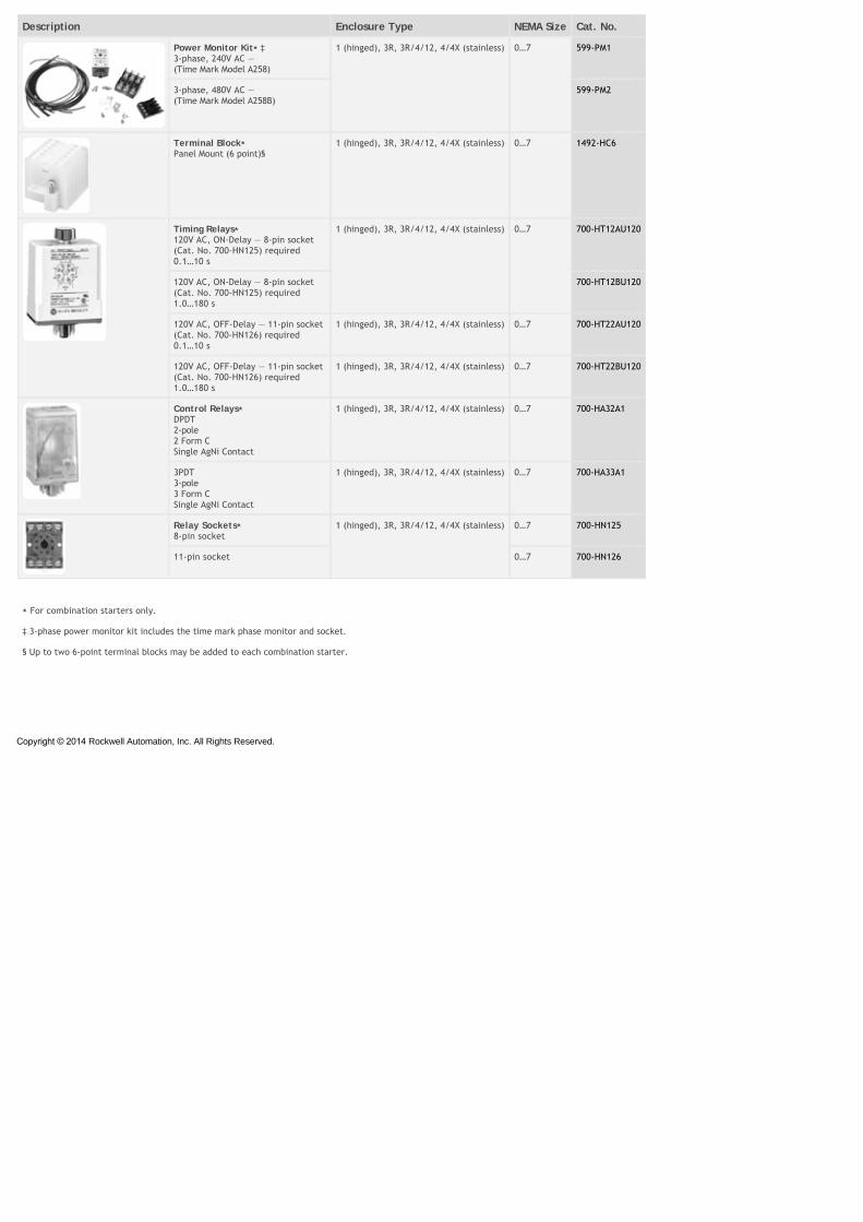
Description Enclosure Type NEMA Size Cat. No.
Power Monitor Kit⋆ ‡ 3-phase, 240V AC — (Time Mark Model A258)
1 (hinged), 3R, 3R/4/12, 4/4X (stainless) 0…7 599-PM1
3-phase, 480V AC — (Time Mark Model A258B)
599-PM2
Terminal Block⋆ Panel Mount (6 point)§
1 (hinged), 3R, 3R/4/12, 4/4X (stainless) 0…7 1492-HC6
Timing Relays⋆ 120V AC, ON-Delay — 8-pin socket (Cat. No. 700-HN125) required0.1…10 s
1 (hinged), 3R, 3R/4/12, 4/4X (stainless) 0…7 700-HT12AU120
120V AC, ON-Delay — 8-pin socket (Cat. No. 700-HN125) required1.0…180 s
700-HT12BU120
120V AC, OFF-Delay — 11-pin socket (Cat. No. 700-HN126) required 0.1…10 s
1 (hinged), 3R, 3R/4/12, 4/4X (stainless) 0…7 700-HT22AU120
120V AC, OFF-Delay — 11-pin socket (Cat. No. 700-HN126) required 1.0…180 s
1 (hinged), 3R, 3R/4/12, 4/4X (stainless) 0…7 700-HT22BU120
Control Relays⋆ DPDT2-pole2 Form CSingle AgNi Contact
1 (hinged), 3R, 3R/4/12, 4/4X (stainless) 0…7 700-HA32A1
3PDT3-pole3 Form CSingle AgNi Contact
1 (hinged), 3R, 3R/4/12, 4/4X (stainless) 0…7 700-HA33A1
Relay Sockets⋆ 8-pin socket
1 (hinged), 3R, 3R/4/12, 4/4X (stainless) 0…7 700-HN125
11-pin socket 0…7 700-HN126
⋆ For combination starters only.
‡ 3-phase power monitor kit includes the time mark phase monitor and socket.
§ Up to two 6-point terminal blocks may be added to each combination starter.
Rockwell Automation, Inc. All Rights Reserved.