Embed Size (px)
Citation preview
Industrial Electrolytic Conductivity Cells Series UDA2182 and APT Specifications 70-82-03-14 July 2009
Main Overview
The specification of an Electrolytic Conductivity Cell
requires careful consideration of the following factors:
1. Appropriate Cell Constant, determined by the
analyzer or recorder used. See instrument range
table.
2. Chemical resistance.
3. Physical nature of mounting; insertion, immersion,
flow through, insertion/removal and laboratory
type.
4. Temperature/pressure rating required.
5. Integral automatic temperature compensator.
Determined by the analyzer or recorder used.
Appropriate Cell Constant - Reference Information
The choice of cell constant is determined by the measuring
instrument and its range.
Cell constant - The cell constant describes the cell’s
geometry. It is the length between electrodes divided by the
effective sample area between them. The standard 1 cm-1
constant cell can be visualized as 2 plates of 1 cm2 area
spaced 1 cm apart. Other cell constants have different
length/area ratios.
Applying the cell constant to the measured
resistance/conductance converts it to resistivity/conductivity
- a property of the fluid independent of the measuring
apparatus and sample size.
Proper cell constant - A variety of cell constants is needed
to measure the complete range of electrolytic solutions from
less than 1. 0 ohms-cm to greater than 18 megohms-cm.
For accuracy, the measured resistance must be at a level
that will give the best sensitivity for the measuring circuit. At
very low measured resistance, polarization effects and
leadwire resistance could affect accuracy.
Output Torque/Full Travel Stroking time is avoided by
choosing a cell constant which will raise the measured
resistance to an acceptable level. At very high resistance
values, leadwire capacitance can affect the accuracy. This
is avoided by selecting a cell that will lower the measured
resistance to an acceptable level.
To measure high purity water, a low cell constant is
specified which lowers the measured resistance.
Conversely, sulfuric acid may have a specific resistance of
1.0 ohm-cm; therefore, a 50 constant cell should be used to
raise the measured resistance to 50 ohms.
Selection Guide for Conductivity Cells
4973 Type Should be quoted whenever possible for
constants 0.01 to 10 cm-1.
When measuring deionized water where the cell has the
potential of being exposed to regeneration acids and bases,
the 4973 cell with its titanium electrodes and rapid
temperature response are preferred.
If a 4905 cell is used, the platinum electrodes are best, but
the nickel (except for Monel electrodes for the 0.1 constant)
electrodes are suitable and should be bid in a competitive
situation.
4905 Type Widest choice of cell constant - should be
quoted on all applications where 4973 is not applicable and
for replacements.
4909 Type Should be quoted when cell removal is required
without disturbing the process.
HFS Catalog_Without Tab_HighRes.pdf 94 6/8/2011 12:41:08 PM
Industrial Electrolytic Conductivity Cells 2
Mounting Configurations
Proper mounting of a cell is as important as any other
parameter. A cell improperly installed may not give an
accurate indication of the true process conditions. Careful
consideration should be given to the mounting.
Insertion Cell can be mounted directly in process stream.
Location should be in rapid fluid motion and in a position
that will prevent sediment accumulation. Also suitable for
lab use.
Immersion Cell can be mounted over a tank or open
trough. The cell should be completely immersed to avoid a
false indication of high resistivity (low conductivity) or
incomplete temperature compensator immersion. Cells
used in this type of installation should utilize a support pipe
of sufficient length to achieve desired immersion depth.
Model 4905 cells are recommended for immersion
mountings.
Flow Cell assembly can be placed directly in process fluid
line or bypass sample line. The cell should be completely
immersed and positioned to prevent accumulation of
sediment to avoid false indication of high resistivity (low
conductivity).
Insertion/Removal cell can be removed at pressures 50
psi or less without disturbing the process.
Automatic Upload of Cell Constant and Cell factor
Conductivity cells have an embedded EEProm that contains
the cell constant and cell factor information. When
connected to the UDA2182 Dual Input Analyzer the
information is automatically uploaded into the unit. There is
no need to manually input the data.
4973 and 4974 Type Overview
These cells are ruggedly constructed for reliable,
continuous measurement of electrolytic conductivity in
industrial water processes at temperatures up to 140°C and
pressures up to 250 psig.
The cells feature polyethersulfone (PES) construction for
high-corrosion resistance, with electrodes of titanium (for
0.01 and 0.1 cell constants) and high-density graphite (for
1.0 and 10.0 cell constants).
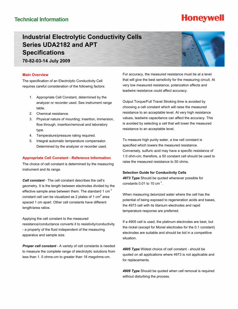
For insertion applications, the 3/4” NPT male thread permits
permanent installation in a pipe or tank; the cell can also be
used as a laboratory dip-type for batch sampling.
For flow applications, the cell can be installed directly into a
process stream, or used with a separately ordered 3/4” pipe
tee in a by-pass stream. The cells have been designed to
keep the electrodes and the temperature compensator
immersed in the stream flow, ensuring that the cell will
respond quickly and accurately to changes in both solution
concentration and temperature.
For sanitary clean-in-place (CIP) piping systems, the 4974
cells include standard 1 1/2” or 2” CIP fittings suitable for
food and beverage, pharmaceutical and cosmetic, or
biotechnology industries.
Connections
Integral cable: The 4973 and 4974 cells offer this option
that provides a cell with a potted cable. The cable and cell
are one entity and cannot be separated. Model 4973 and
4974 cells are not designed for immersion mounting
installations.
Quick disconnect cable: Only the 4973 offers this option
that provides a cell with a potted receptacle. The cable
mates with this receptacle. The cell and cable are separate
entities.
HFS Catalog_Without Tab_HighRes.pdf 95 6/8/2011 12:41:08 PM
Industrial Electrolytic Conductivity Cells 3
Specifications
4973/4974 Type
Automatic Temperature Compensator
Supplied on all cells
Cell Constant 4973/4974: 0.01, 0.1, 1.0, and 10 cm-1
Maximum Temperature Limit 4973: 140°C (284°F) at rated pressure 4974: 130°C (266°F) at rated pressure, may be further limited by CIP gasket and clamp type
Maximum Pressure Limit 4973: 1724 kPa (250 psig) at rated temperature 4974: 1034 kPa (150 psig) at rated temperature, may be further limited by gasket and clamp type
Insertion 4973 cells: 3/4” NPT male thread for schedule 40 and 80 pipe 4974 cells: 1 1/2” or 2” sanitary CIP fitting
Insertion Depth 89 mm (3 1/2”) for 1, 10, and 0.01 constants from solution end of 3/4” NPT male thread 64 mm (2 1/2”) for 0.1 constant
Wetted Parts Cell body: PES (polyethersulfone) Electrodes: 0.01 and 0.1 constant, titanium; 1.0 and 10.0 constant, high-density graphite with Teflon guard. 4974 series also includes food grade silicone rubber and polished 316 S.S.
Lead wire 4973/4974: Integral PVC-covered, shielded, 22-gage cable. If more than 50’ is required, specify the junction box head and the required length of extension cable (head has 3/4” female NPT with 1/2” female adapter bushing) conduit connection). For a separate junction box, specify part number 31316260, and appropriate length of cable.
Electrical Connections 4973:Integral cable – 6 leads with integral Automatic Temperature Compensator
Quick disconnect option – mating head with cable must be purchased from Honeywell.
4974: Integral cable – 6 leads with integral Automatic Temperature Compensator
Weight 4973: 0.2 kg (0.5 lb.) 4974: 0.4 kg (1 lb.)
Approvals 4973: Manufactured to comply with ASME boiler and pressure vessel code Section VIII, Div. 1, UG-101. CRN #0F11607-5C
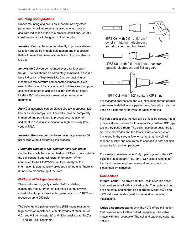
Flow Chambers for 4973
055919 Max. Flow: 5 gpm at 40 psig Material: PES Max. Pressure: 200 psig at 25°C Max. Temperature: 140°C at 5 psig Dimensions: 38 mm x 222 mm (1 1/2” x 8 1/4”) Sample Inlet: ¾” NPTM Sample Outlet: ¾” NPTF
HFS Catalog_Without Tab_HighRes.pdf 96 6/8/2011 12:41:08 PM
Industrial Electrolytic Conductivity Cells 4
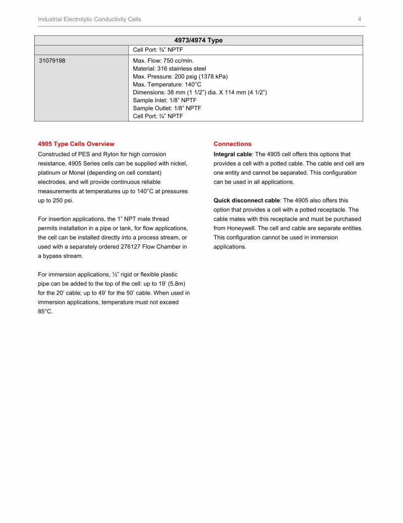
4973/4974 Type
Cell Port: ¾” NPTF
31079198 Max. Flow: 750 cc/min. Material: 316 stainless steel Max. Pressure: 200 psig (1378 kPa) Max. Temperature: 140°C Dimensions: 38 mm (1 1/2”) dia. X 114 mm (4 1/2”) Sample Inlet: 1/8” NPTF Sample Outlet: 1/8” NPTF Cell Port: ¾” NPTF
4905 Type Cells Overview
Constructed of PES and Ryton for high corrosion
resistance, 4905 Series cells can be supplied with nickel,
platinum or Monel (depending on cell constant)
electrodes, and will provide continuous reliable
measurements at temperatures up to 140°C at pressures
up to 250 psi.
For insertion applications, the 1” NPT male thread
permits installation in a pipe or tank, for flow applications,
the cell can be installed directly into a process stream, or
used with a separately ordered 276127 Flow Chamber in
a bypass stream.
For immersion applications, ½” rigid or flexible plastic
pipe can be added to the top of the cell: up to 19’ (5.8m)
for the 20’ cable; up to 49’ for the 50’ cable. When used in
immersion applications, temperature must not exceed
85°C.
Connections
Integral cable: The 4905 cell offers this options that
provides a cell with a potted cable. The cable and cell are
one entity and cannot be separated. This configuration
can be used in all applications.
Quick disconnect cable: The 4905 also offers this
option that provides a cell with a potted receptacle. The
cable mates with this receptacle and must be purchased
from Honeywell. The cell and cable are separate entities.
This configuration cannot be used in immersion
applications.
HFS Catalog_Without Tab_HighRes.pdf 97 6/8/2011 12:41:08 PM
Industrial Electrolytic Conductivity Cells 5
Specifications
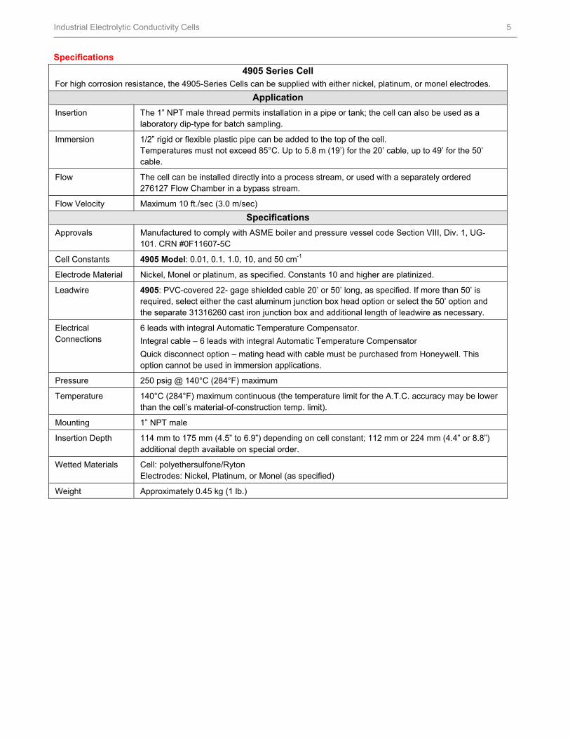
4905 Series Cell For high corrosion resistance, the 4905-Series Cells can be supplied with either nickel, platinum, or monel electrodes.
Application
Insertion The 1” NPT male thread permits installation in a pipe or tank; the cell can also be used as a laboratory dip-type for batch sampling.
Immersion 1/2” rigid or flexible plastic pipe can be added to the top of the cell. Temperatures must not exceed 85°C. Up to 5.8 m (19’) for the 20’ cable, up to 49’ for the 50’ cable.
Flow The cell can be installed directly into a process stream, or used with a separately ordered 276127 Flow Chamber in a bypass stream.
Flow Velocity Maximum 10 ft./sec (3.0 m/sec)
Specifications
Approvals Manufactured to comply with ASME boiler and pressure vessel code Section VIII, Div. 1, UG-101. CRN #0F11607-5C
Cell Constants 4905 Model: 0.01, 0.1, 1.0, 10, and 50 cm-1
Electrode Material Nickel, Monel or platinum, as specified. Constants 10 and higher are platinized.
Leadwire 4905: PVC-covered 22- gage shielded cable 20’ or 50’ long, as specified. If more than 50’ is required, select either the cast aluminum junction box head option or select the 50’ option and the separate 31316260 cast iron junction box and additional length of leadwire as necessary.
Electrical Connections
6 leads with integral Automatic Temperature Compensator.
Integral cable – 6 leads with integral Automatic Temperature Compensator
Quick disconnect option – mating head with cable must be purchased from Honeywell. This option cannot be used in immersion applications.
Pressure 250 psig @ 140°C (284°F) maximum
Temperature 140°C (284°F) maximum continuous (the temperature limit for the A.T.C. accuracy may be lower than the cell’s material-of-construction temp. limit).
Mounting 1” NPT male
Insertion Depth 114 mm to 175 mm (4.5” to 6.9”) depending on cell constant; 112 mm or 224 mm (4.4” or 8.8”) additional depth available on special order.
Wetted Materials Cell: polyethersulfone/Ryton Electrodes: Nickel, Platinum, or Monel (as specified)
Weight Approximately 0.45 kg (1 lb.)
HFS Catalog_Without Tab_HighRes.pdf 98 6/8/2011 12:41:08 PM
Industrial Electrolytic Conductivity Cells 6
Specifications
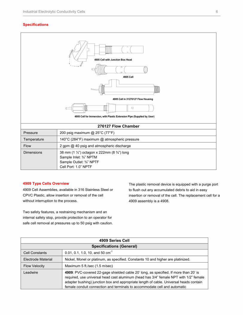
276127 Flow Chamber
Pressure 200 psig maximum @ 25°C (77°F)
Temperature 140°C (284°F) maximum @ atmospheric pressure
Flow 2 gpm @ 40 psig and atmospheric discharge
Dimensions 38 mm (1 ½”) octagon x 222mm (8 ¾”) long Sample Inlet: ¾” NPTM Sample Outlet: ¾” NPTF Cell Port: 1.0” NPTF
4909 Type Cells Overview
4909 Cell Assemblies, available in 316 Stainless Steel or
CPVC Plastic, allow insertion or removal of the cell
without interruption to the process.
Two safety features, a restraining mechanism and an
internal safety stop, provide protection to an operator for
safe cell removal at pressures up to 50 psig with caution.
The plastic removal device is equipped with a purge port
to flush out any accumulated debris to aid in easy
insertion or removal of the cell. The replacement cell for a
4909 assembly is a 4908.
4909 Series Cell
Specifications (General)
Cell Constants 0.01, 0.1, 1.0, 10, and 50 cm-1
Electrode Material Nickel, Monel or platinum, as specified. Constants 10 and higher are platinized.
Flow Velocity Maximum 5 ft./sec (1.5 m/sec)
Leadwire 4909: PVC-covered 22-gage shielded cable 20’ long, as specified. If more than 20’ is required, use universal head cast aluminum (head has 3/4” female NPT with 1/2” female adapter bushing) junction box and appropriate length of cable. Universal heads contain female conduit connection and terminals to accommodate cell and automatic
4905 Cell
4905 Cell in 31276127 Flow Housing
4905 Cell for Immersion, with Plastic Extension Pipe (Supplied by User)
4905 Cell with Junction Box Head
HFS Catalog_Without Tab_HighRes.pdf 99 6/8/2011 12:41:08 PM
Industrial Electrolytic Conductivity Cells 7
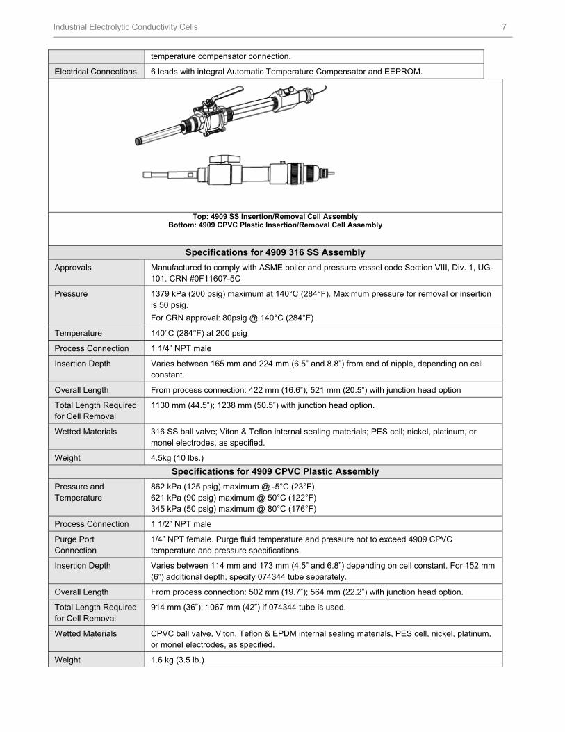
Top: 4909 SS Insertion/Removal Cell AssemblyBottom: 4909 CPVC Plastic Insertion/Removal Cell Assembly
Specifications for 4909 316 SS Assembly
Approvals Manufactured to comply with ASME boiler and pressure vessel code Section VIII, Div. 1, UG-101. CRN #0F11607-5C
Pressure 1379 kPa (200 psig) maximum at 140°C (284°F). Maximum pressure for removal or insertion is 50 psig.
For CRN approval: 80psig @ 140°C (284°F)
Temperature 140°C (284°F) at 200 psig
Process Connection 1 1/4” NPT male
Insertion Depth Varies between 165 mm and 224 mm (6.5” and 8.8”) from end of nipple, depending on cell constant.
Overall Length From process connection: 422 mm (16.6”); 521 mm (20.5”) with junction head option
Total Length Required for Cell Removal
1130 mm (44.5”); 1238 mm (50.5”) with junction head option.
Wetted Materials 316 SS ball valve; Viton & Teflon internal sealing materials; PES cell; nickel, platinum, or monel electrodes, as specified.
Weight 4.5kg (10 lbs.)
Specifications for 4909 CPVC Plastic Assembly
Pressure and Temperature
862 kPa (125 psig) maximum @ -5°C (23°F) 621 kPa (90 psig) maximum @ 50°C (122°F) 345 kPa (50 psig) maximum @ 80°C (176°F)
Process Connection 1 1/2” NPT male
Purge Port Connection
1/4” NPT female. Purge fluid temperature and pressure not to exceed 4909 CPVC temperature and pressure specifications.
Insertion Depth Varies between 114 mm and 173 mm (4.5” and 6.8”) depending on cell constant. For 152 mm (6”) additional depth, specify 074344 tube separately.
Overall Length From process connection: 502 mm (19.7”); 564 mm (22.2”) with junction head option.
Total Length Required for Cell Removal
914 mm (36”); 1067 mm (42”) if 074344 tube is used.
Wetted Materials CPVC ball valve, Viton, Teflon & EPDM internal sealing materials, PES cell, nickel, platinum, or monel electrodes, as specified.
Weight 1.6 kg (3.5 lb.)
temperature compensator connection.
Electrical Connections 6 leads with integral Automatic Temperature Compensator and EEPROM.
HFS Catalog_Without Tab_HighRes.pdf 100 6/8/2011 12:41:08 PM
Industrial Electrolytic Conductivity Cells 8
For More Information
Learn more about how Honeywell’s Industrial
Electrolytic Conductivity cells are the most reliable in
conductivity measurements, visit our website
www.honeywell.com/ps/hfs or contact your Honeywell
account manager.
Honeywell Process Solutions
1860 West Rose Garden Lane
Phoenix, Arizona 85027
Tel: 1-800-423-9883 or 1-800-343-0228 www.honeywell.com/ps
Warranty/Remedy
Honeywell warrants goods of its manufacture as being free of defective materials and faulty workmanship. Contact your local
sales office for warranty information.
If warranted goods are returned to Honeywell during the period of coverage, Honeywell will repair or replace without charge
those items it finds defective. The foregoing is Buyer's sole remedy and is in lieu of all other warranties, expressed or
implied, including those of merchantability and fitness for a particular purpose.
Specifications may change without notice. The information we supply is believed to be accurate and reliable as of this
printing. However, we assume no responsibility for its use.
While we provide application assistance personally, through our literature and the Honeywell web site, it is up to the
customer to determine the suitability of the product in the application.
70-82-03-14 July 2009 © 2010 Honeywell International Inc.
HFS Catalog_Without Tab_HighRes.pdf 101 6/8/2011 12:41:08 PM