Embed Size (px)
Citation preview
INDUSTRIAL FAN SALES – FAN FACTS
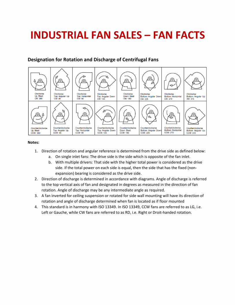
Designation for Rotation and Discharge of Centrifugal Fans
Notes:
1. Direction of rotation and angular reference is determined from the drive side as defined below:
a. On single inlet fans: The drive side is the side which is opposite of the fan inlet.
b. With multiple drivers: That side with the higher total power is considered as the drive
side. If the total power on each side is equal, then the side that has the fixed (non-
expansion) bearing is considered as the drive side.
2. Direction of discharge is determined in accordance with diagrams. Angle of discharge is referred
to the top vertical axis of fan and designated in degrees as measured in the direction of fan
rotation. Angle of discharge may be any intermediate angle as required.
3. A fan inverted for ceiling suspension or rotated for side wall mounting will have its direction of
rotation and angle of discharge determined when fan is located as if floor mounted
4. This standard is in harmony with ISO 13349. In ISO 13349, CCW fans are referred to as LG, i.e.
Left or Gauche, while CW fans are referred to as RD, i.e. Right or Droit-handed rotation.
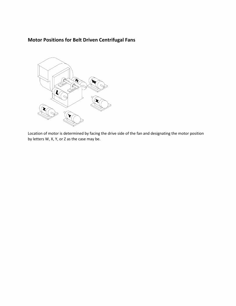
Motor Positions for Belt Driven Centrifugal Fans
Location of motor is determined by facing the drive side of the fan and designating the motor position
by letters W, X, Y, or Z as the case may be.
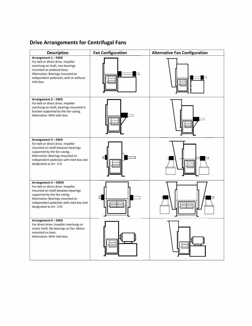
Drive Arrangements for Centrifugal Fans
Description Fan Configuration Alternative Fan Configuration Arrangement 1 – SWSI
For belt or direct drive. Impeller
overhung on shaft, two bearings
mounted on pedestal base.
Alternative: Bearings mounted on
independent pedestals, with or without
inlet box.
Arrangement 2 – SWSI
For belt or direct drive. Impeller
overhung on shaft, bearings mounted in
bracket supported by the fan casing.
Alternative: With inlet box.
Arrangement 3 – SWSI
For belt or direct drive. Impeller
mounted on shaft between bearings
supported by the fan casing.
Alternative: Bearings mounted on
independent pedestals with inlet box and
designated as Arr. 3 SI.
Arrangement 3 – DWDI
For belt or direct drive. Impeller
mounted on shaft between bearings
supported by the fan casing.
Alternative: Bearings mounted on
independent pedestals with inlet box and
designated as Arr. 3 DI.
Arrangement 4 – SWSI
For direct drive. Impeller overhung on
motor shaft. No bearings on fan. Motor
mounted on base.
Alternative: With inlet box.
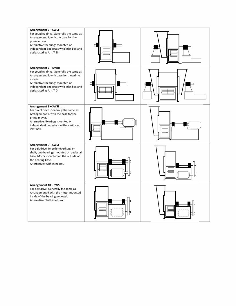
Arrangement 7 – SWSI
For coupling drive. Generally the same as
Arrangement 3, with the base for the
prime mover.
Alternative: Bearings mounted on
independent pedestals with inlet box and
designated as Arr. 7 SI.
Arrangement 7 – DWDI
For coupling drive. Generally the same as
Arrangement 3, with base for the prime
mover.
Alternative: Bearings mounted on
independent pedestals with inlet box and
designated as Arr. 7 DI
Arrangement 8 – SWSI
For direct drive. Generally the same as
Arrangement 1, with the base for the
prime mover.
Alternative: Bearings mounted on
independent pedestals, with or without
inlet box.
Arrangement 9 – SWSI
For belt drive. Impeller overhung on
shaft, two bearings mounted on pedestal
base. Motor mounted on the outside of
the bearing base.
Alternative: With Inlet box.
Arrangement 10 – SWSI
For belt drive. Generally the same as
Arrangement 9 with the motor mounted
inside of the bearing pedestal.
Alternative: With inlet box.
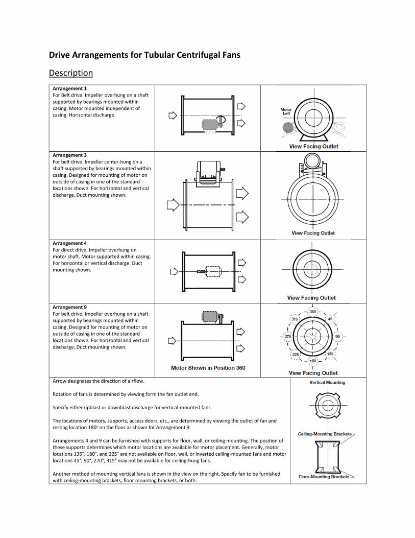
Drive Arrangements for Tubular Centrifugal Fans
Description
Arrangement 1
For Belt drive. Impeller overhung on a shaft
supported by bearings mounted within
casing. Motor mounted independent of
casing. Horizontal discharge.
Arrangement 3
For belt drive. Impeller center-hung on a
shaft supported by bearings mounted within
casing. Designed for mounting of motor on
outside of casing in one of the standard
locations shown. For horizontal and vertical
discharge. Duct mounting shown.
Arrangement 4
For direct drive. Impeller overhung on
motor shaft. Motor supported within casing.
For horizontal or vertical discharge. Duct
mounting shown.
Arrangement 9
For belt drive. Impeller overhung on a shaft
supported by bearings mounted within
casing. Designed for mounting of motor on
outside of casing in one of the standard
locations shown. For horizontal and vertical
discharge. Duct mounting shown.
Arrow designates the direction of airflow.
Rotation of fans is determined by viewing form the fan outlet end.
Specify either upblast or downblast discharge for vertical-mounted fans.
The locations of motors, supports, access doors, etc., are determined by viewing the outlet of fan and
resting location 180o on the floor as shown for Arrangement 9.
Arrangements 4 and 9 can be furnished with supports for floor, wall, or ceiling mounting. The position of
these supports determines which motor locations are available for motor placement. Generally, motor
locations 135°, 180°, and 225° are not available on floor, wall, or inverted ceiling-mounted fans and motor
locations 45°, 90°, 270°, 315° may not be available for ceiling-hung fans.
Another method of mounting vertical fans is shown in the view on the right. Specify fan to be furnished
with ceiling-mounting brackets, floor mounting brackets, or both.
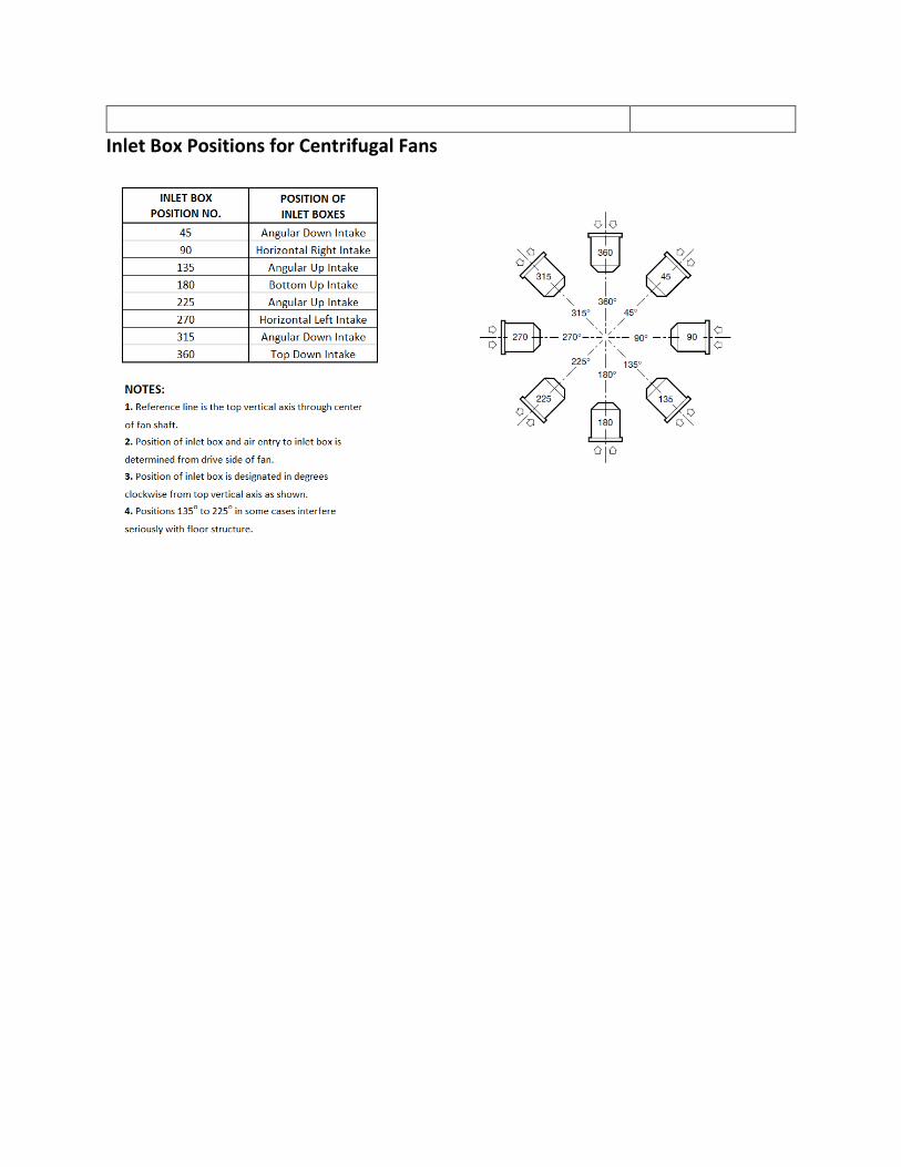
Inlet Box Positions for Centrifugal Fans
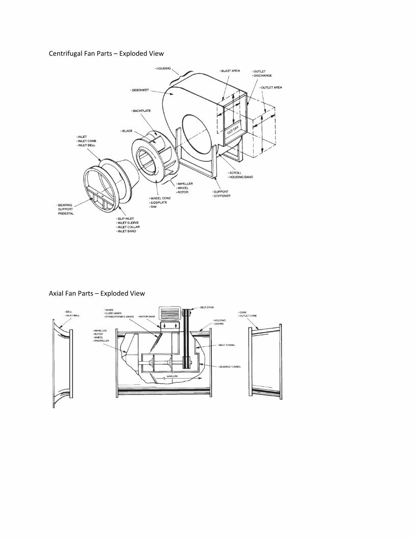
Centrifugal Fan Parts – Exploded View
Axial Fan Parts – Exploded View
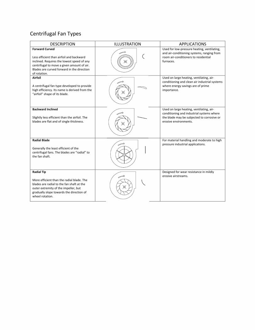
Centrifugal Fan Types
DESCRIPTION ILLUSTRATION APPLICATIONS Forward Curved
Less efficient than airfoil and backward
inclined. Requires the lowest speed of any
centrifugal to move a given amount of air.
Blades are curved forward in the direction
of rotation.
Used for low-pressure heating, ventilating,
and air-conditioning systems, ranging from
room air-conditioners to residential
furnaces.
Airfoil
A centrifugal fan type developed to provide
high efficiency. Its name is derived from the
“airfoil” shape of its blade.
Used on large heating, ventilating, air-
conditioning and clean air industrial systems
where energy savings are of prime
importance.
Backward Inclined
Slightly less efficient than the airfoil. The
blades are flat and of single thickness.
Used on large heating, ventilating, air-
conditioning and industrial systems where
the blade may be subjected to corrosive or
erosive environments.
Radial Blade
Generally the least efficient of the
centrifugal fans. The blades are “radial” to
the fan shaft.
For material handling and moderate to high
pressure industrial applications.
Radial Tip
More efficient than the radial blade. The
blades are radial to the fan shaft at the
outer extremity of the impeller, but
gradually slope towards the direction of
wheel rotation.
Designed for wear resistance in mildly
erosive airstreams.
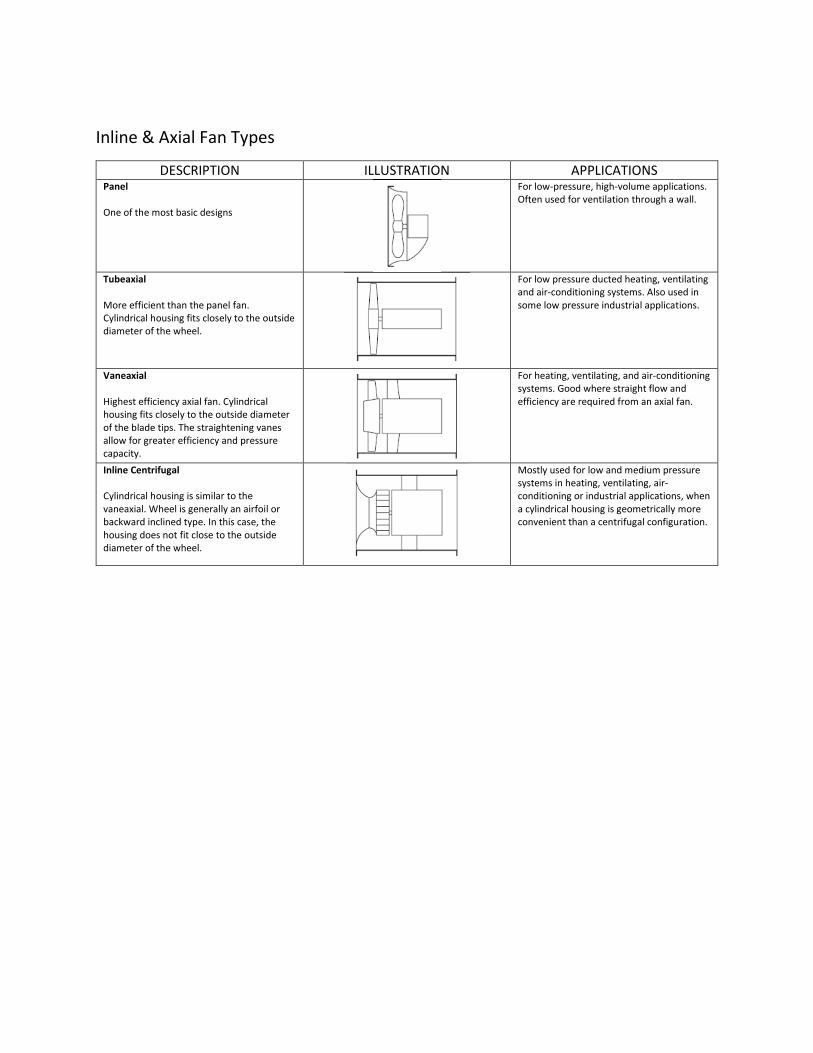
Inline & Axial Fan Types
DESCRIPTION ILLUSTRATION APPLICATIONS Panel
One of the most basic designs
For low-pressure, high-volume applications.
Often used for ventilation through a wall.
Tubeaxial
More efficient than the panel fan.
Cylindrical housing fits closely to the outside
diameter of the wheel.
For low pressure ducted heating, ventilating
and air-conditioning systems. Also used in
some low pressure industrial applications.
Vaneaxial
Highest efficiency axial fan. Cylindrical
housing fits closely to the outside diameter
of the blade tips. The straightening vanes
allow for greater efficiency and pressure
capacity.
For heating, ventilating, and air-conditioning
systems. Good where straight flow and
efficiency are required from an axial fan.
Inline Centrifugal
Cylindrical housing is similar to the
vaneaxial. Wheel is generally an airfoil or
backward inclined type. In this case, the
housing does not fit close to the outside
diameter of the wheel.
Mostly used for low and medium pressure
systems in heating, ventilating, air-
conditioning or industrial applications, when
a cylindrical housing is geometrically more
convenient than a centrifugal configuration.