Embed Size (px)
Citation preview

®
Industrial Gas and Fire Safety Panel
System Manual Model 800
Publication REV F
810 Russell Palmer Road Kingwood, Texas 77339 P.O. Box 6092 Kingwood, Texas 77325 Phone: 281-359-1519 Fax: 281-359-2085 Email: [email protected]
Gas and Fire System Integration
in a Single Enclosure

Page 3
ALLESTEC 800 INDUSTRIAL GAS / FIRE CONTROL PANEL AUTOMATIC SUPPRESSION SYSTEM
© 1993-2014 ALLESTEC CORPORATION REVISION DATE 5/10/2014
REVISION F OPERATIONS MANUAL PART NUMBER 800-1185
ONGUARD is a registered trade mark and trade name for Allestec Corporation
DEPARTMENT ____________________________________________ NAME ___________________________________________________ PHONE NUMBER _________________________________________ DATE ___________________________________________________
Page 4
Table Of Contents 1. INTRODUCTION ...................................................................................................................... 8 2. SPECIFICATIONS .................................................................................................................. 10 2.1 GENERAL ....................................................................................................................... 10 2.2 ENVIRONMENT ............................................................................................................. 10 2.3 MODULE SPECIFIC ....................................................................................................... 10 3. INSTALLATION ..................................................................................................................... 12
3.1 BENCH TOP TRIAL ........................................................................................................ 12 3.2 PANEL MOUNTING ....................................................................................................... 12 3.3 FIELD WIRE INSTALLATION ......................................................................................... 12 3.4 STANDARD ENCLOSURE ............................................................................................. 20 3.5 PANEL TERMINAL STRIPS ........................................................................................... 20 3.6 POWER SUPPLY REQUIREMENT ................................................................................ 21 3.7 EARTH GROUND ........................................................................................................... 21 3.8 ZONING THE MODULE WITHIN THE RACK .............................................................. 21 3.9 MODULE INSTALLATION - LOCATION - RESTRICTIONS ........................................... 21 3.10 BLANK (SPARE) MODULE ……………………………………………….…………………..22 3.11 SPECIFIC FUNCTIONS ................................................................................................. 22 3.12 POWER UP RESET ....................................................................................................... 22 3.13 LED INDICATORS .......................................................................................................... 22 3.14 FUSE MONITORING ...................................................................................................... 22 3.15 SYSTEM BUSS .............................................................................................................. 22 4. INPUT MODULE .................................................................................................................... 24 4.1 VOTING .......................................................................................................................... 24 4.2 TIME DELAY .................................................................................................................. 24 4.3 AUXILIARY FIRE RELAY ............................................................................................... 25 4.4 BELL / HORN / STROBE ................................................................................................ 25 4.5 AGENT RELEASE SOLENOID ...................................................................................... 25 4.6 MODULE REMOVAL ALARM ......................................................................................... 25 4.7 FAULT INDICATION ....................................................................................................... 25 4.8 DETECTOR CONNECTION ........................................................................................... 25 4.9 DETECTOR TEST SWITCH SW3 (OPTION) ................................................................. 25 4.10 INPUT MODULE DIP SWITCH SELECTIONS ............................................................... 26 4.11 PANEL TERMINAL STRIP DESIGNATIONS ................................................................. 27 5. INPUT VOTE MODULE .......................................................................................................... 28
5.1 MODULE TYPES ............................................................................................................ 28 5.2 TIME DELAY (OPTIONAL) ............................................................................................. 28 5.3 VOTING .......................................................................................................................... 29 5.4 FIRE DELAY ................................................................................................................... 29 5.5 OPEN COLLECTOR OUTPUT ....................................................................................... 29 5.6 FAULT INDICATION ....................................................................................................... 29 5.7 DETECTOR MANUAL TEST SWITCH (OPTIONAL)...................................................... 30 5.8 JUMPER LOCATION ...................................................................................................... 30 5.9 DETECTOR POWER OUTPUT ...................................................................................... 30 5.10 MASTER INPUT VOTE MODULE DIP SWITCH SELECTIONS .................................... 31 5.11 SLAVE INPUT MODULE DIP SWITCH SELECTIONS .................................................. 31 5.12 PANEL TERMINAL STRIP DESIGNATIONS ................................................................. 32 5.13 INPUT VOTING MODULE PART NUMBER ................................................................... 32

Page 5
Table Of Contents
6. MANUAL PULL MODULE ..................................................................................................... 33 6.1 INHIBIT ........................................................................................................................... 33 6.2 FAULT ANNUNCIATION ................................................................................................ 33 6.3 TERMINAL STRIP DESIGNATION ................................................................................ 33 6.4 MANUAL PULL DIP SWITCH SELECTIONS ................................................................. 34 7. ALARM MODULE .................................................................................................................. 35 7.1 REMOTE BELL / HORN SILENCE ................................................................................. 35 7.2 AUXILIARY / REMOTE ALARM INPUT .......................................................................... 35 7.3 MODULE REMOVAL ALARM ......................................................................................... 35 7.4 FAULT INDICATION ....................................................................................................... 35 7.5 OPTIONAL TEXT OVERLAYS ....................................................................................... 35 7.6 ALARM MODULE DIP SWITCH SELECTIONS ............................................................. 36 7.7 PANEL TERMINAL STRIP DESIGNATIONS ................................................................. 37 8. RELEASE MODULE ............................................................................................................. 38
8.1 OPERATING PROCEDURES ....................................................................................... 38 8.2 SOLENOID SPECIFICATION ........................................................................................ 39 8.3 PROGRAMMING THE RELEASE MODULE ................................................................. 39 8.4 INPUT MODULE ALARM .............................................................................................. 40 8.5 MANUAL PULL ALARM (INSTANT) ............................................................................. 41 8.6 MANUAL PULL ALARM (TIMED) ................................................................................ 41 8.7 MANUAL PULL ALARM (EXCLUSIVE) ........................................................................ 41 8.8 INHIBIT (DISABLE MODE) ............................................................................................ 41 8.9 DISCHARGE RELAY ..................................................................................................... 41 8.10 FAULTS ......................................................................................................................... 42 8.11 JUMPER SELECTIONS ................................................................................................ 42 8.12 PANEL TERMINAL STRIP DESIGNATIONS ............................................................... 43 9. WATER MIST (CYCLE) RELEASE MODULE ...................................................................... 44
9.1 APPLICATIONS .............................................................................................................. 44 9.2 OPERATION .................................................................................................................. 44 9.3 INSTALLATION ............................................................................................................. 44 9.4 SOLENOID SPECIFICATION ........................................................................................ 44 9.5 POWER UP .................................................................................................................... 44 9.6 PROGRAMMING ........................................................................................................... 44 9.7 PROGRAM DATA ......................................................................................................... 45 9.8 INPUT MODULE ALARM .............................................................................................. 45 9.9 MANUAL PULL ALARM ................................................................................................. 45 9.10 INHIBIT (DISABLE) ........................................................................................................ 45 9.11 MODULE RESET .......................................................................................................... 45 9.12 DETAIL OF CYCLE EVENTS ........................................................................................ 46 9.13 PRE-DISCHARGE ......................................................................................................... 46 9.14 WATER MIST ON ......................................................................................................... 46 9.15 WATER MIST OFF ........................................................................................................ 46 9.16 PAUSE MODE ………………………………………………………………………………….46 9.17 RELAY FUNCTIONS ..................................................................................................... 46 9.18 MODULE FAULTS ........................................................................................................ 46 9.19 EXTERNAL RESET ....................................................................................................... 46 9.20 INTERNAL CONTROL ................................................................................................... 47 9.21 PLC/CLOCK OUTPUT ................................................................................................... 47 9.22 AUDIBLE ALARM .......................................................................................................... 47 9.23 MODULE REMOVAL ALARM ………………………………………………………………...47

Page 6
Table Of Contents 10. RELAY MODULE ................................................................................................................. 48 10.1 RELAY OUTPUT FUNCTIONS .................................................................................. 48 10.2 ALARM ACKNOWLEDGING ...................................................................................... 48 10.3 RELAY MODULE DIP SWITCH SELECTIONS .......................................................... 48 11. FAULT MODULE .................................................................................................................. 50
11.1 OUTPUT RELAY ......................................................................................................... 50 11.2 BATTERY / POWER SUPERVISION .......................................................................... 50 11.3 AUXILIARY FAULT INPUT .......................................................................................... 50 11.4 TERMINAL STRIP DESIGNATIONS ........................................................................... 50 11.5 FAULT MODULE DIP SWITCH SELECTIONS ........................................................... 51 12. ABORT MODULE .................................................................................................................. 52 12.1 AUDIBLE ALARM ......................................................................................................... 52 12.2 POWER LED ................................................................................................................ 52 12.3 TB1-8 EXTERNAL CLOCK INPUT ............................................................................... 52 12.4 ALLESTEC 800 PANEL CONNECTION ....................................................................... 52 12.5 CONTROL PANEL BY OTHERS CONNECTION ......................................................... 52 12.6 MOUNTING HOLE DIMENSIONS ................................................................................ 52 12.7 TERMINAL DESIGNATIONS - ALLESTEC ABORT PANEL ........................................ 52 12.8 TERMINAL DESIGNATIONS - PANELS BY OTHERS ................................................. 52 12.9 TIME COUNTDOWN SETTINGS ................................................................................. 53 13. GAS MODULE ....................................................................................................................... 54
13.1 FIELD WIRE INSTALLATION ....................................................................................... 54 13.2 FIRST MODULE IDENTIFICATION.. ............................................................................ 55 13.3 POWER UP RESET ..................................................................................................... 55 13.4 VERSION and CONFIGURATION ................................................................................ 55 13.5 PANEL NUMERIC DISPLAY ........................................................................................ 55 13.6 PANEL LED’S and RELAYS ........................................................................................ 55 13.7 PANEL SWITCHES ...................................................................................................... 55 13.8 FAULT RESET ............................................................................................................. 55 13.9 MODULE FRONT VIEWS ............................................................................................. 56 13.10 PROGRAM FAMILIARITY ............................................................................................ 57 13.11 CONFIGURATION TABLE ........................................................................................... 58 13.12 PROGRAM MODE - Entering / Exiting ......................................................................... 59 13.13 SELECTING THE LATCHING FEATURE ..................................................................... 59 13.14 VIEW DATA .................................................................................................................. 59 13.15 EXITING AND SAVING PROGRAM ............................................................................. 59 13.16 DEVIATIONS ................................................................................................................ 59 13.17 PROGRAMMING FOR THE C1 COMBUSTIBLE GAS CONFIGURATION .................. 60 13.18 AC MODE - Reading..................................................................................................... 60 13.19 HH (HI HI) Set Point - Adjusting rising alarms .............................................................. 60 13.20 HI SET POINT - Adjusting rising alarms ....................................................................... 60 13.21 Lo SET POINT - Adjusting rising alarms ....................................................................... 60 13.22 Lo ALARM LATCH ........................................................................................................ 60 13.23 FL FAULT LATCH - Fault alarm output ........................................................................ 60 13.24 CALIBRATION TECHNIQUE ........................................................................................ 60 13.25 STANDARD CALIBRATION ......................................................................................... 61 13.26 CL - CALIBRATE Lo (Zero) .......................................................................................... 61 13.27 CH - CALIBRATE HIGH (Span) .................................................................................... 61

Page 7
Table Of Contents 13.28 ALTERNATIVE REMOTE CALIBRATION PREPARATION.......................................... 62 13.29 CL - CALIBRATE Lo (Zero) .......................................................................................... 62 13.30 CH - CALIBRATE High (Span) ..................................................................................... 62 13.31 REMOTE CALIBRATION.............................................................................................. 62 13.32 d0 - DISPLAY ZERO (Dead Band) ............................................................................... 63 13.33 ALARM SET POINTS - C1 Only Agency Restrictions ................................................. 63 13.34 PROGRAMMING FOR THE C2-C4 H2S GAS CONFIGURATION .............................. 64 13.35 INTRODUCTION .......................................................................................................... 64 13.36 HH (HIGH HIGH) ALARM LATCHING .......................................................................... 64 13.37 HI (HIGH) ALARM LATCHING ..................................................................................... 64 13.38 Lo (LOW) ALARM LATCHING ...................................................................................... 64 13.39 VIEWING DISPLAY FRACTIONAL INTEGERS ........................................................... 64 13.40 PROGRAMMING FOR THE OXYGEN GAS CONFIGURATION ................................. 65 13.41 INTRODUCTION .......................................................................................................... 65 13.42 SET POINT THRESHOLD LEVELS ............................................................................. 65 13.43 HI (HIGH) SET POINT - Adjusting rising alarms ........................................................... 65 13.44 L1 SET POINT - Adjusting falling alarms ...................................................................... 65 13.45 L2 SET POINT - Adjusting falling alarms ...................................................................... 65 13.46 HI (HIGH) ALARM LATCHING ..................................................................................... 65 13.47 L1 (LOW 1) ALARM LATCHING ................................................................................... 65 13.48 L2 (LOW2) ALARM LATCHING .................................................................................... 65 13.49 VIEWING DISPLAY FRACTIONAL INTEGERS ........................................................... 65 13.50 RELAY OUTPUT SELECTIONS FOR C1 THROUGH C4 CONFIGURATIONS ........... 66 13.51 ALARM MODULE COMMUNICATION C1-C4 .............................................................. 66 13.52 RELAY OUTPUT FOR C5 OXYGEN CONFIGURATION ............................................. 67 13.53 ALARM MODULE COMMUNICATION C5.................................................................... 67 13.54 FAULT ANNUNCIATION .............................................................................................. 68 13.55 INDUCED FAULTS ....................................................................................................... 68 13.56 MALFUNCTION FAULTS ............................................................................................. 68 13.57 TERMINAL BLOCK DESIGNATIONS........................................................................... 68 13.58 REMOTE RESET ......................................................................................................... 68 13.59 FAULT EXTERNAL OUTPUT ....................................................................................... 68 13.60 RECORDER OUTPUT (optional) .................................................................................. 68 13.61 PART NUMBER INFORMATION .................................................................................. 68 14. APPROVED DETECTOR AND APPLIANCE COMPONENTS ............................................ 69 15. MAINTENANCE ................................................................................................................... 69 16. WARRANTY ........................................................................................................................ 70

Page 8
1. INTRODUCTION The installer must read these instructions carefully and fully understand the operation of this system prior to entering it into service. Save this manual and any related documentation for future reference. WARNING: This manual is to be reviewed by qualified service and installation personnel only. To avoid injury and / or electrical shock, do not perform any installation or servicing other than that contained in this manual, unless qualified.
The Allestec series 800 Fire / Gas Panel is primarily designed to interface to stand-alone optical fire de-tector heads, four wire smoke detectors, and gas transmitters, activating suppression systems utilizing the Class B configuration. Various modules consist of the basic panel to provide a complete non-coded system to accept industrial detector outputs and appliances. The modules can be utilized as stand-alone in some signaling applications. The flexible rack housing allows users to purchase up to 16 modules as expansion is needed. All modules incorporated into the panel communicate to each other through the rear motherboard to eliminate external wiring. System designers can select the various modules below to satisfy the requirement for a complete system. Duplicated modules within the same rack are permitted to allow expansion. The front locking panel door, P/N 1192-XX is required to meet NFPA requirements for fire modules, unless the panel is located behind a locking cabinet with a viewing window.
Input Module: FM Approved CE Listed 800-1440
Accepts up to three optical or four wire smoke detectors with dry relay contacts and the ability to vote between the three channels. Once activated by a detector, the Input Module can initiate the Release, Alarm and Relay Module.
Input Vote Module: CE Listed 800-1530
Accepts up to two optical or four wire smoke detectors with dry relay contacts and the ability to vote between each channel or vote between other Input Vote Modules. Once activated by a detector, the Input Vote Module can initiate the Release, Alarm and Relay Module.
Manual Pull Module: FM Approved CE Listed 800-1441
Accepts Manual Pull Stations in parallel and has an inhibit feature. Once acti-vated by a Manual Pull Station, the module can initiate the Release, Alarm and Relay Module.
Alarm Module: FM Approved CE Listed 800-1442
The Input, Manual Pull, or Gas Module activates this module. When activated, the Alarm Module will sound the audible appliance devices and turn on the strobe. This module can be activated and silenced remotely.
Release Module: FM Approved CE Listed 800-1443D
The Input or Manual Pull module activates the Release module. This module can be selected to activate a main and / or reserve tank through the program. Pa-rameters are selected for timed or instant release. This module has an inhibit feature to test the system.
Water Mist Release Module: CE Listed 800-2800
The Input or Manual Pull module activates the Release module. This module is programmed to cycle the water mist solenoid valve on/off for various lengths of time, then stand by for observing post ignition occurrence. This module conforms to the NFPA 750.
Relay Module: FM Approved CE Listed 800-1760
Auxiliary relay outputs are provided from this module. Three separate relays can trip on a general, auxiliary or fault alarm. The module has an audible alarm that can be silenced and has different sounds than other modules.

Page 9
Fault Module: FM Approved CE Listed 800-1444
System malfunctions will be annunciated from the Fault Module. The Fault Mod-ule is common to all modules in the mounting rack. This module has an auxiliary fault input.
Abort Module: FM Approved 800-1436
Single digital display counts down remaining time until discharge. Various modes of operation are available from the Release Module. The Abort Module can be utilized in the Allestec panel or panels by other manufacturers.
Abort Module: FM Approved 800-1437
Dual digital display counts down remaining time for two independent discharge systems. The Abort Module can be utilized in the Allestec panel or panels by other manufacturers.
Gas Module: 800-1457 FM Approved CE Listed
The NT420 Gas Module accepts industrial standard 4-20mA output and can communicate to the Alarm, Relay and Fault Module. Systems requiring only gas detection may utilize the module exclusively. Three alarm points are controlled by an integral microprocessor, programmable from the front panel. This module can accept combustible, toxic or oxygen sensor inputs.
Locking Enclosure: FM Approved CE Listed 800-1192
Accommodates all 800 series modules into a standard 19” EIA rack. Rack size available is from 2 to 16 slots. This enclosure has an acrylic window that will lock, allowing full view of the modules.
Open Enclosure: 800-1690 CE Listed
Accommodates all 800 series modules into a standard 19” EIA rack. Rack size available is from 2 to 16 slots. This enclosure has an architect low profile style bezel.
Blank Face Plate: FM Approved CE Listed 800-1315
Accommodates unoccupied slots of the rack. Module includes a jumper to allow for the required designation of the first occupied slot. One of these style face plates are required per rack if a spare slot is accommodated.
Blank Face Plate: FM Approved CE Listed 800-1785
Accommodates unoccupied slots of the rack. Can be located anywhere except as the first module.

Page 10
2. SPECIFICATIONS
2.1 GENERAL System operating voltage: 20 – 28 VDC, 24V nominal. Alarm Module supervised relay outputs – fused for 2A, 24VDC, each channel. PCB construction: 1/16” 2 OZ., FR-4 fiberglass, double sided, plated through holes, solder mask. Module size: 3.5”H X 1”W X 7” deep. Rack: Steel, yellow zinc chromate finish.
2.2 ENVIRONMENTAL Operating ambient temperature: 0 Degrees Fahrenheit to 150 Degrees Fahrenheit. Operating humidity: non-condensing 0 – 90%.
2.3 MODULE SPECIFIC
Input Module: FM Approved CE Listed 800-1440
Operating Current @ 24 VDC quiescent: 31mA, alarm: 65mA. Fuse: Module power: F1 1/20A micro fuse. Detector head power fuse: F2 2A micro fuse. Dry relay output: 5A 30VDC , or 125, 250VAC. End of line resistor: 3.9K .5W 5% carbon composition P/N 1211.
Input Vote Module: CE Listed 800-1530
Operating Current @ 24 VDC quiescent: 30mA, alarm: 54mA. Fuse: Module power : F1 1/20A micro fuse P/N 1335. Detector head power fuse: F2 3A micro fuse P/N 1529. Fire relay output: 5A 30VDC, or 125, 250VAC. Relay configuration: DPST. Open collector output: Normally energized – sinks 500mA @ 24VDC continu-ous. End of line resistor: 3.9K .5W 5% carbon composition P/N 1211.
Manual Pull Module: FM Approved CE Listed 800-1441
Operating Current @ 24 VDC quiescent: 25mA, alarm: 42mA. Fuse: Module power : F1 1/32A 5mm glass. Dry relay output: 5A 30 VDC. End of line resistor: 3.9K .5W 5% carbon composition P/N 1211.
Alarm Module: FM Approved CE Listed 800-1442
Operating Current @ 24 VDC quiescent: 30mA, alarm: 90mA (excluding appli-ance circuits). Fuse: Module power : F1 1/32A 5mm glass. Bell F2 2A, Horn F3 2A, Strobe F4 2A. Supervised relay outputs: Each relay – 2A 24VDC. End of line resistor: 3.9K .5W 5% carbon composition P/N 1211.
Release Module: FM Approved CE Listed 800-1443D
Operating Current @ 24 VDC quiescent: 70mA, alarm: 107mA – no load. Supervised relay outputs fused: Each relay - 4A 24 VDC F1, F2 P/N 1269. Discharge Relay: SPDT 5A 30 VDC, 250 VAC dry contact. Contact Allestec for larger solenoid load requirements.
Water Mist Release Module: CE Listed 800-2800
Operating Current @ 24 VDC quiescent: 70mA, alarm: 70mA no load. Supervised relay outputs fused: 3A nominal, 6A surge electronic auto-reset, non-replaceable. Fault relay output: SPDT 5A 30 VDC, 250VAC dry contact. Contact Allestec for larger solenoid load requirements.

Page 11
Relay Module: FM Approved CE Listed 800-1760
Operating Current @ 24 VDC quiescent, 20mA, maximum 95mA. Three dry relay outputs each SPDT: 5A 30VDC, 250 VAC.
Fault Module: FM approved CE Listed 800-1444
Operating Current @ 24 VDC quiescent: 31mA, maximum 40mA. Fuse: Module power F1 50mA P/N 1010. Dry relay output: 5A 30VDC.
Abort Module: FM Approved 800-1436/1437
Operating current @ 24VDC: Primary board: 18mA quiescent, 105mA maximum. Secondary board option (including primary board): 21mA quiescent, 185mA maximum. Fuse F1: Primary board: 125mA P/N 1394. Secondary board installed: 250mA P/N 1414. Audible: Audible alarm pulses 1 cycle per second during countdown. Frequency: 3.8KHz @ 75dB 1m. Mounting: Standard 3 gang wall mount switch box. Bezel: Stainless Steel.
Gas Module: FM Approved CE Listed 800-1457
Operating current @ 24V, 130mA maximum @ 20mA sensor input; 85mA quiescent at 4mA sensor input. Dry relay alarm outputs: 5 amps, 30VDC resistive, 250VAC. Fault output: Open collector transistor – sinks 24VDC at 1 amp. Gas sensor fuse: Maximum fuse – 3A P/N 1529. Display: Red 7 segment display: Low scale displays ur for under range readings below -9. High scale displays 1H for 100, then or for over range and OC for over current. Dominant wavelength: 640nm. Size: .3” high Weight: 4.8 Oz. Operational Features: Optional 4-20mA recorder output. Open collector fault transistor output. Over range, under range, fault annunciation. Three levels of alarm set points activate associated relays. Real time digital display of 0-25mA current in program mode. Module is able to interface to any standard 4-20mA output device. Able to read and display %LFL, PPM, %OXYGEN. Compatible with all model 800 modules. Set points, relay functions, calibrations are fully programmable from front panel. Design Features: Linear scale, digital filter, 100 millisecond sampling rate. integral microprocessor design. true analog to digital conversion, memory retention with loss of power, input power reverse polarity protected, true digital display representation of loop current.

Page 12
3. INSTALLATION
3.1 BENCH TOP TRIAL It is highly recommended that the entire system be connected on a bench top to establish correct module DIP switch locations and operating verification. Connect initiating devices, appliances and solenoids with-out their respective tanks to emulate an actual alarm sequence. Become familiar with the various options available and know what the sequence of events of the panel are, before permanently installing the sys-tem. NOTE: After resetting any module, allow two seconds to expire before proceeding to another function.
3.2 PANEL MOUNTING Refer to Figure 2 to identify the spacing of the panel mounting holes. Locate the panel in a secure struc-ture free from high vibration, rain, airborne particles and condensation. The panel is designed to be lo-cated in the interior of a building, NEMA 1 environment.
3.3 FIELD WIRE INSTALLATION The electrical conduit and wiring must be installed in accordance with the following agencies: National Fire Protection Agency, National Electrical Code, local and State jurisdiction having authority. Color coded wires are recommended for ease of identification while installing the system. The use of stranded copper wire is recommended. The field wire diagram of Figures 4,5,6,8 illustrates the modules configured with inputs and outputs being utilized for a typical installation. CAUTION: Power and ground wire gauge must be of sufficient size to ensure that the voltage drop at the maximum current draw will not reduce operating voltage at the last initiating detector or appliance to less than manufacturers recommended rating. Solenoid circuits will have no more than 5 ohms resistance per each conductor. Bell, horn and strobe will have no more than 5 ohms resistance per each conductor. 16 AWG is the minimum recommended wire size for the output appliance circuits. The initiating device relay signal conductors will have no more than 10 ohms resistance per each single conductor. All other panel signal wiring will have no more than 10 ohms resistance per each conductor. 18 AWG wire is the minimum size recommended for these signal field wires. Wire size smaller than 20 AWG is not recommended for installation.
DO NOT LOCATE PANEL SIGNAL / SENSORY WIRES IN CONDUIT WITH AC POWER OR ANY TYPE OF LINE THAT MAY CONTAIN AC POWER AND FREQUENCY COMPONENTS THAT ARE REPRESENTATIVE OF AC VOLTAGES. ISOLATE SIG-NAL / SENSORY WIRES FROM AC CARRYING WIRES.

Page 13
Figure 1. Complete assembled view (ten channel rack illustrated)

Page 14
Figure 2. Recommended panel cut-out

Page 15
Figure 3. Exploded view assembly

Page 16
Figure 4. Field wire installation
Page 17
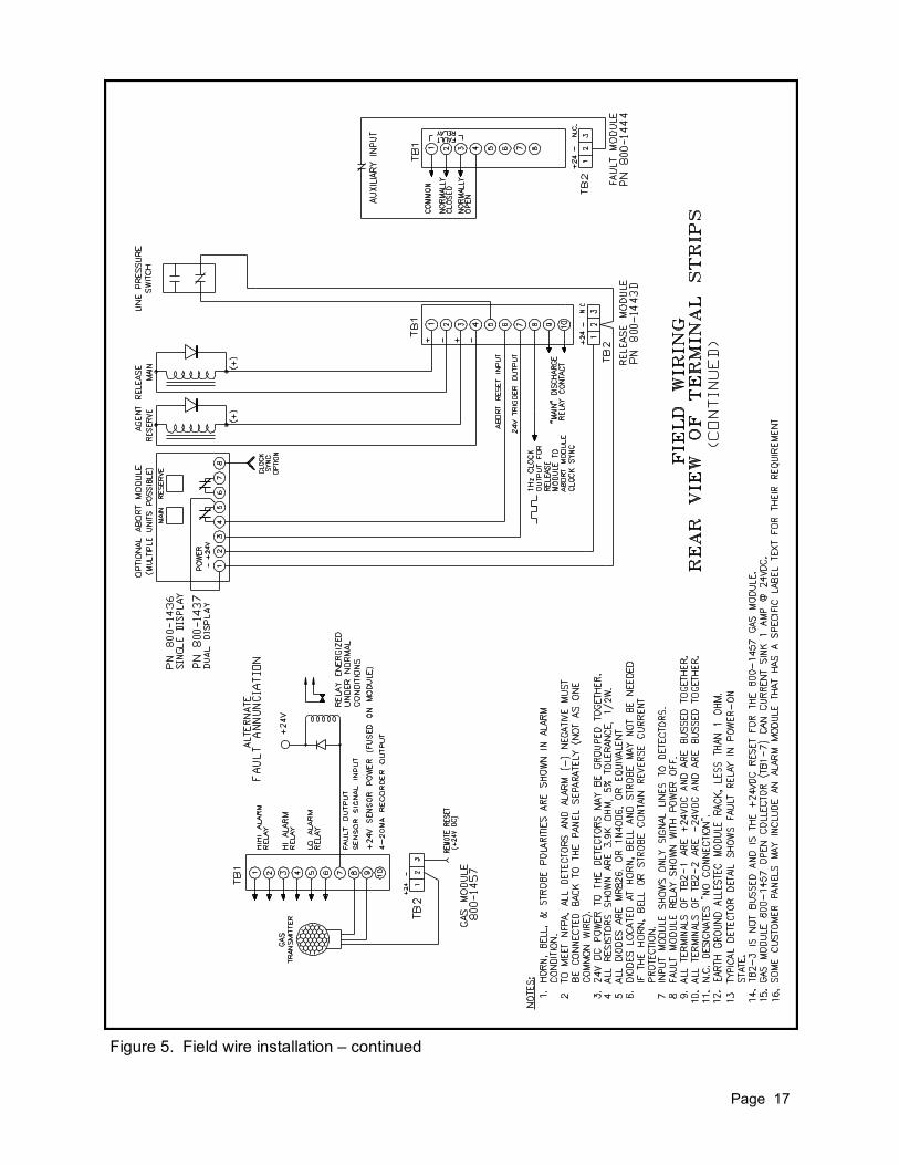
Figure 5. Field wire installation – continued
Page 18
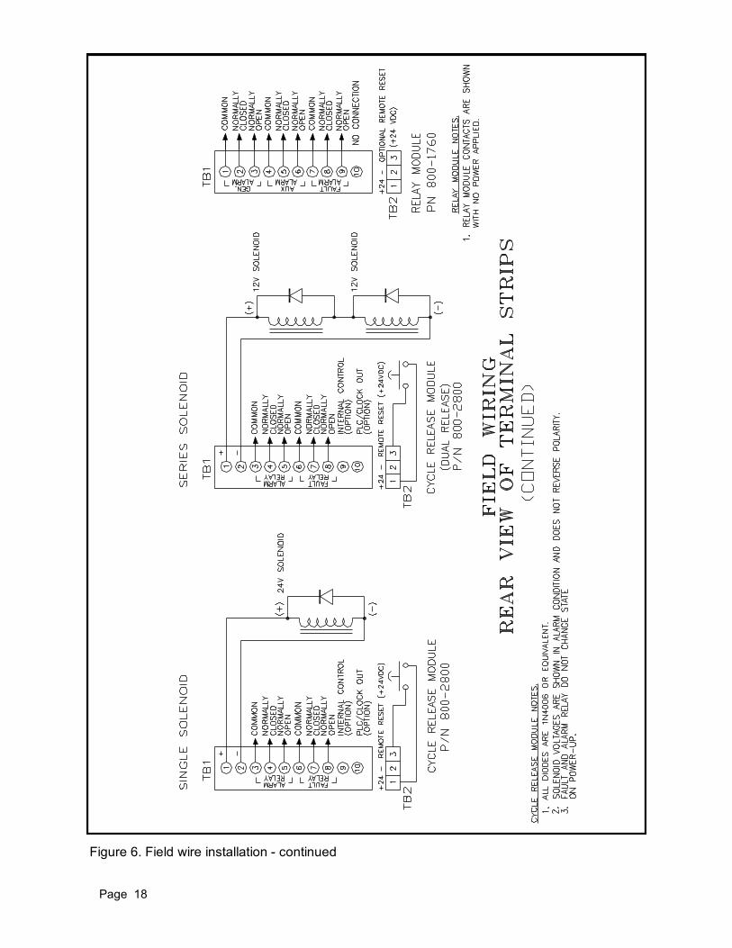
Figure 6. Field wire installation - continued

Page 19
Figure 8. Field wire connections on Abort Module
Figure 7. Hole location to mount Abort Module bezel

Page 20
3.4 STANDARD ENCLOSURE The standard EIA 19 inch rack will accept from two to sixteen modules. The user can specify the amount of slots required to satisfy the installation and will specify additional slots if future expansion is required. When fully expanded, the rack will consist of the following: ● Sixteen, ten-slot terminal strips mounted to the rear of the panel designated as TB1. Electrical connec-
tions for appliances, signal wires and detectors are connected here.
● Twelve, three-slot terminal strips mounted to the rear of the panel designated as TB2. These terminals will allow the power and negative to be connected to the motherboard. Input terminal #1 of TB2 is the +24VDC and terminal # 2 is common to negative. These terminal strips are electrically connected on the motherboard.
● Electrical connections on the motherboard to route signals to and from each module. The positive +24V connections are bussed together and are located at TB2-1 on the rear of the panel. Connect the redundant power supply positive to any one of these TB2-1 locations. All negative connec-tions are bussed together and are located at TB2-2. Connect the power supply negative to TB2-2. TB2-3 is utilized for a common reset on specified modules or as a deviation port.
3.5 PANEL TERMINAL STRIPS With the power disconnected, connect the field wiring to the terminal strips as shown in the respective wiring diagram. Strip off just enough insulation from the wire until the bare wire reaches to the bottom of the mounting terminal and then secure the terminal screw. When connecting wires to the terminal strips, it is imperative that no frayed wires make contact to adjacent terminals, especially where there may be AC power connected to the auxiliary relay contact terminals. Wire diagrams illustrating the rear panel view of the terminal strips will include some terminal strips where there will be no connection (N.C.). Refer to the field wiring diagrams for more specifics and Figure 9 for terminal strip designations.
Figure 9. Eight channel rack (rear view)
Page 21
3.6 POWER SUPPLY REQUIREMENT This panel can be utilized only in installations capable of supplying DC power where two independent and reliable DC power sources are available. The recommended power backup should be rated to sup-ply enough reserve power to provide for the entire system for 24 hours. The power source must include a main power supply to power the system and a backup power supply in the event that the main power is lost. In most applications, the standard arrangement would include a power supply connected to 115VAC with the same source charging the backup batteries. This backup power supply must not inter-fere with the operation of the panel if the primary power is lost. Refer to the NFPA 72 requirements to satisfy the correct procedure for supplying DC power to the system.
CAUTION: UNDER NO CIRCUMSTANCES SHOULD THE CUSTOMER CIRCUMVENT THE DUAL POWER SYSTEM REQUIRED FOR THE SYSTEM AS DESCRIBED ABOVE.
CAUTION: DO NOT INSERT OR REMOVE ANY MODULE WHILE THE SYSTEM IS UNDER POWER OR ACCIDENTAL AGENT DISCHARGE MAY RESULT IF UTILIZING THE RELEASE MODULE. For calculating the correct 24 VDC regulated power supply, add the maximum power of each detector, module and appliance. Add 25% of that calculation back into the Figure. Example: 2 Detector Heads 10 Watts 4 Modules 26 Watts Including two solenoids rated at 67 ohms Horn 20 Watts Strobe 25 Watts ———— TOTAL 81 Watts 25% of ~80 20 Hence, Minimum required: ~100 Watt power supply @ 24VDC. Observe conditions where the rise of ambient temperature requires power supply de-rating. Read the primary and backup power supply specification sheet for more information. Although some applications utilize an earth grounded power supply, Allestec recommends the power supply be floating.
3.7 EARTH GROUND Connect a conductor no less than 1 ohm resistance from the chassis to Earth ground as shown in Figure 4. This connection must be in accordance with Article 760 of the National Electric Code.
3.8 ZONING THE MODULES WITHIN THE RACK The rear terminal panel can be configured to zone specified modules by Allestec. The Fault Module will remain common to all modules. Contact Allestec if the system requirement has to change to a zoned configuration.
3.9 MODULE INSTALLATION - LOCATION - RESTRICTIONS To install the modules into the rack, turn the mounting screw located on the front panel of the module counter clockwise until it stops, then insert the module into the rack between the lower and upper nylon rails, pushing the module toward the back until it snaps into place. Secure the module by turning the same screw clockwise until it stops. The spare blank installs the same way as a standard module and its latching mechanism is the same.
The location of modules within the rack is at the discretion of the installer, however the Fault Module must always be the last module located to the right of other modules (except the blank modules), as viewed from the front. After a module has been located in the rack and wired, the module must remain at that location. Multiple modules may be placed in the same rack provided the customer understands the full operation of the complete system and that moving a wired module to another slot must require that the associated wiring also be moved. The rack can accommodate all fire modules and gas modules, or a combination of both types of protection.
Page 22
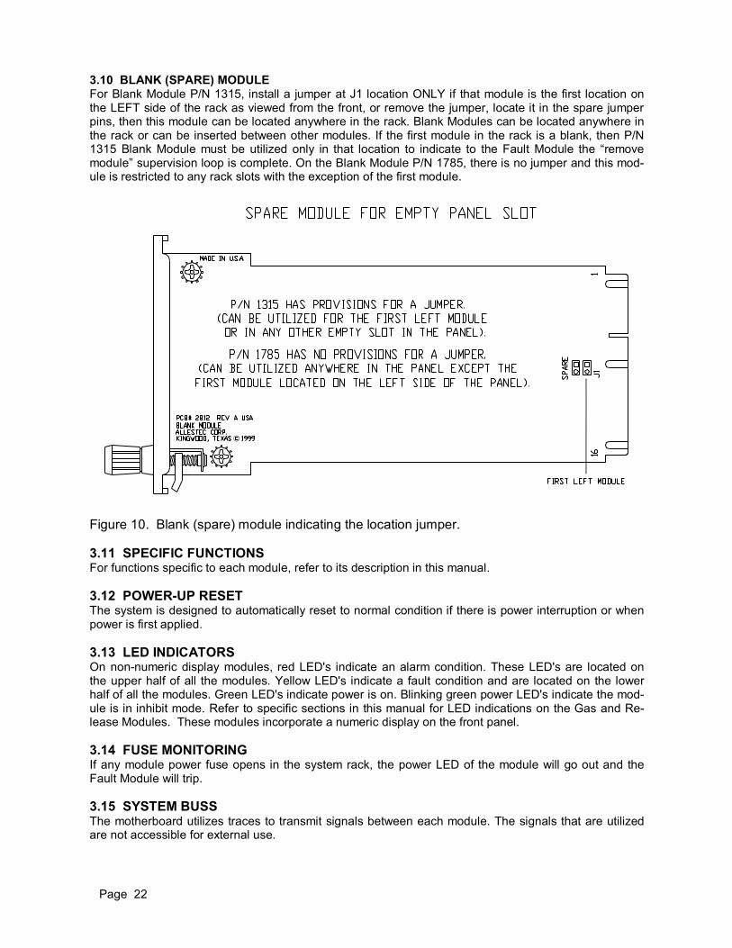
3.10 BLANK (SPARE) MODULE For Blank Module P/N 1315, install a jumper at J1 location ONLY if that module is the first location on the LEFT side of the rack as viewed from the front, or remove the jumper, locate it in the spare jumper pins, then this module can be located anywhere in the rack. Blank Modules can be located anywhere in the rack or can be inserted between other modules. If the first module in the rack is a blank, then P/N 1315 Blank Module must be utilized only in that location to indicate to the Fault Module the “remove module” supervision loop is complete. On the Blank Module P/N 1785, there is no jumper and this mod-ule is restricted to any rack slots with the exception of the first module.
Figure 10. Blank (spare) module indicating the location jumper.
3.11 SPECIFIC FUNCTIONS For functions specific to each module, refer to its description in this manual.
3.12 POWER-UP RESET The system is designed to automatically reset to normal condition if there is power interruption or when power is first applied.
3.13 LED INDICATORS On non-numeric display modules, red LED's indicate an alarm condition. These LED's are located on the upper half of all the modules. Yellow LED's indicate a fault condition and are located on the lower half of all the modules. Green LED's indicate power is on. Blinking green power LED's indicate the mod-ule is in inhibit mode. Refer to specific sections in this manual for LED indications on the Gas and Re-lease Modules. These modules incorporate a numeric display on the front panel.
3.14 FUSE MONITORING If any module power fuse opens in the system rack, the power LED of the module will go out and the Fault Module will trip.
3.15 SYSTEM BUSS The motherboard utilizes traces to transmit signals between each module. The signals that are utilized are not accessible for external use.

Page 23
Figure 11. Module front views and their respective label numbers as follows: 800 - (module number) - (label number)
Figure 12. Abort Module front view Model 800-1436
Figure 13. Abort Module front view Model 800-1437

Page 24
4. INPUT MODULE (800-1440) The Input Module is the primary module that monitors detector head dry relay contacts to trip the sys-tem. This 3 channel module can be duplicated in the system to add more points of fire annunciation as required. To maintain a fully automatic operation, the system is designed to be utilized for non-latching detectors; although, latching detectors may be utilized in some special applications. When activated by a detector, the fire LED will turn on as long as the detector remains in alarm. When the alarm clears, the LED will blink to indicate there has been a relay contact closure on the respective input. The module can be reset when all alarms on this module have been cleared. The activation of the Input Module automatically initiates the Alarm, Relay and Release Module. Refer to the specific modules to determine their operation during an alarm condition.
4.1 VOTING Refer to the DIP switch selections to set the Input Module voting parameters. Refer to section 4.10 for their operations. Voting channels must be actuated by the detectors simultaneously to trip the Input Module if voting is utilized. Voting can be utilized where the absolute confirmation of a fire exists, reducing false alarms. Allestec does not recommend any standard switch configurations, since installations vary with design procedures and environmental conditions. CAUTION: THE INTRODUCTION OF VOTING AND / OR TIME DELAYS WILL SLOW THE FIRE DETECTION TIME.
If a nuisance alarm trips one detector for no apparent reason, the Input Module fire LED will trip and latch on that particular channel. The resulting blinking LED indicates that there is a potential for the Input Module fire output to trip because one channel registered a valid input condition, even though it may have been an unwanted signal. Observe this type of warning signs to alleviate any possible false alarms.
4.2 TIME DELAY The Input Module incorporates an adjustable time delay for use with detector heads that require filtering nuisance alarm signals before it is deemed a valid alarm. Spurious IR or UV radiation, such as lightning, can trigger the detector head alarm relay for a short period of time that could result in a false alarm. The time delay will allow the Input Module to be adjusted to ignore these unwanted signals. R3, R4, and R5 are 4 turn potentiometers utilized to adjust the amount of time lapse after the detector alarm relay closes. One clockwise revolution of the POTs equals approximately 4 seconds, and each POT may be adjusted independently of each other. The maximum time of each POT is approximately 12 seconds. If, for an example, R3 POT is adjusted for 5 seconds, and the module is not voting, the Input Module fire alarm output signal will trip 5 seconds after the detector head fire relay trips. If the detector head relay opens before the 5 seconds expire, the timer automatically resets and waits for another continuous 5 second detector head relay closure. NOTE: If the voting switch is selected to trip when any detector alarms, the Input Module fire output
signal will trip on the POT that is adjusted to the shorter delay. If the voting switches are voting between detectors, the Input Module fire output signal will trip on the POT that is adjusted to the longer delay. Test the arrangement prior to entering into service.
Page 25
NOTE:
4.3 AUXILIARY FIRE RELAY The Input Module has a SPDT alarm relay that changes state if an alarm occurs. This relay can be set to activate on the first or voted alarm, latching or non- latching. The relay contacts are rated at 5A, 30VDC resistive, or 5A 250VAC.
4.4 BELL / HORN / STROBE The Input Module can be programmed to trip the bell / horn / strobe (refer to Alarm Module) on the first alarm or the voted alarm. The Alarm Module will activate immediately after the Input Module has con-firmed the fire signal.
4.5 AGENT RELEASE SOLENOID The Input Module can be programmed to energize the solenoid (refer to Release Module) on the first alarm or voted alarm. Refer to the DIP switch selections.
4.6 MODULE REMOVAL ALARM If this module is to be located at the left side of the rack, switch SW1-1 must be closed. This switch com-pletes the supervision loop of the Fault Module. Should the Input Module be pulled out of the rack, the Fault Module will trip.
4.7 FAULT INDICATION An open conductor in any of the three fire input lines will turn on the front panel fault yellow LED and trip the Fault Module. The audible alarm can be silenced while locating the problem. Each fault LED repre-sents the numerical fire channel of the above fire LED's. Fire 1 - Fault 1, Fire 2 - Fault 2, Fire 3 - Fault 3.
4.8 DETECTOR CONNECTION The detector head power, TB1-7 will support detectors requiring no more than a total of 2A. This termi-nal is fused with fuse F2. NOTE: The Input Module will not reset if this fuse is open.
4.9 DETECTOR TEST SWITCH SW3 (OPTION) A recessed panel switch, SW3, is utilized for detectors that employ remote test features. This switch ac-commodates the three channels and can be enabled to source or sink 24VDC @ .8VA. Use the supplied test rod to depress the recessed front panel switch. Identify the J1 jumper location below for the correct selection. The connection for the test feature is provided at TB1-8. Multiple detectors can be daisy chained together and when the test switch is depressed, all detectors will enter into alarm simultane-ously.
CAUTION: Based on the detector requirements for the test feature, refer to the jumper location below:
J1-1 Test switch contact normally open. J1-2 Test switch contact normally closed. J1-3 Test switch contact sources +24VDC. J1-4 Test switch contact sinks +24VDC to negative.
If time delay is correct for the Input Module, the time must be considered when setting the time in the Release Module. The time from the Input Module will be added to the time of the Re-lease Module.
DEPRESSING THE DETECTOR SWITCH, SW3, WILL ALARM THE DETEC-TORS CONNECTED TO THE INPUT MODULE. PROPER DISABLING OF THE SYSTEM MUST BE PROVIDED OR A DISCHARGE RELEASE WILL OCCUR.
Page 26
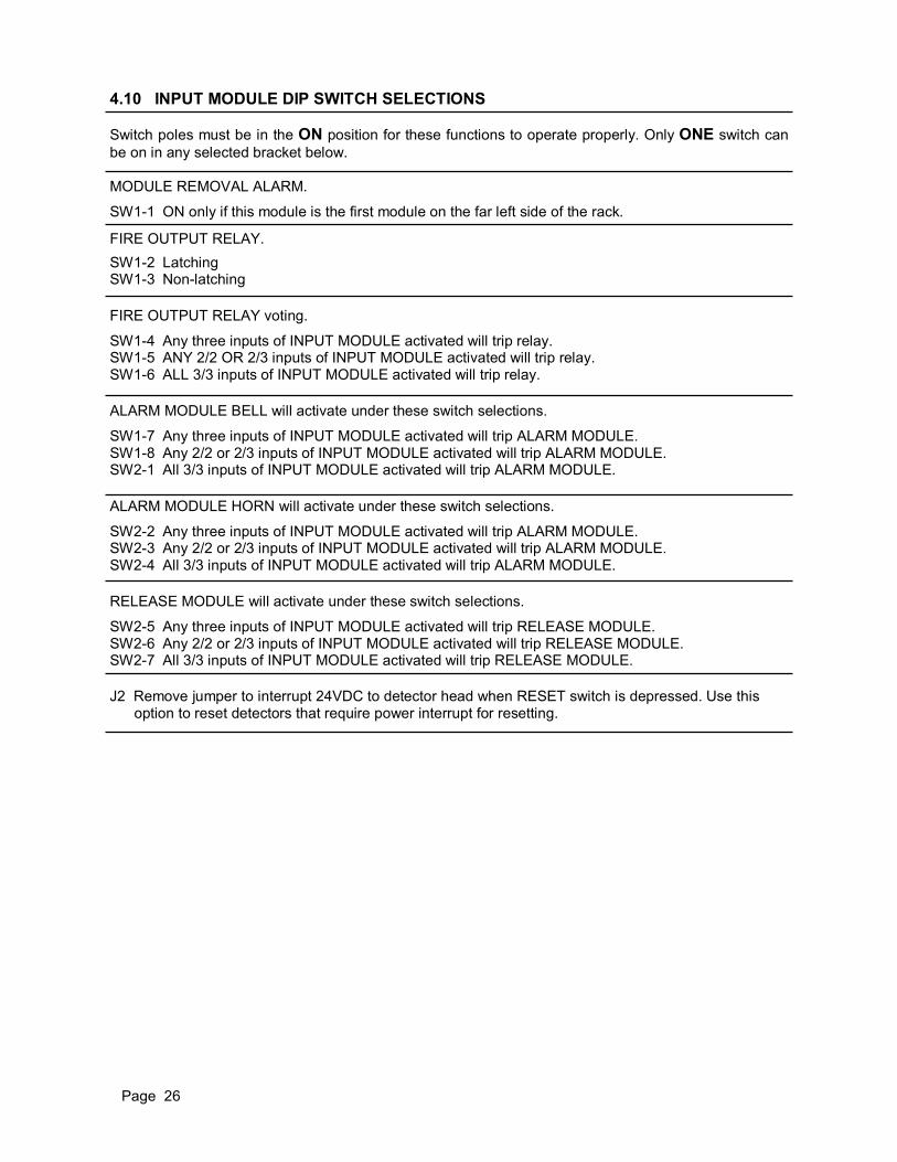
4.10 INPUT MODULE DIP SWITCH SELECTIONS
Switch poles must be in the ON position for these functions to operate properly. Only ONE switch can
be on in any selected bracket below.
MODULE REMOVAL ALARM.
SW1-1 ON only if this module is the first module on the far left side of the rack.
FIRE OUTPUT RELAY.
SW1-2 Latching SW1-3 Non-latching
FIRE OUTPUT RELAY voting.
SW1-4 Any three inputs of INPUT MODULE activated will trip relay. SW1-5 ANY 2/2 OR 2/3 inputs of INPUT MODULE activated will trip relay. SW1-6 ALL 3/3 inputs of INPUT MODULE activated will trip relay.
ALARM MODULE BELL will activate under these switch selections.
SW1-7 Any three inputs of INPUT MODULE activated will trip ALARM MODULE. SW1-8 Any 2/2 or 2/3 inputs of INPUT MODULE activated will trip ALARM MODULE. SW2-1 All 3/3 inputs of INPUT MODULE activated will trip ALARM MODULE.
ALARM MODULE HORN will activate under these switch selections.
SW2-2 Any three inputs of INPUT MODULE activated will trip ALARM MODULE. SW2-3 Any 2/2 or 2/3 inputs of INPUT MODULE activated will trip ALARM MODULE. SW2-4 All 3/3 inputs of INPUT MODULE activated will trip ALARM MODULE.
RELEASE MODULE will activate under these switch selections.
SW2-5 Any three inputs of INPUT MODULE activated will trip RELEASE MODULE. SW2-6 Any 2/2 or 2/3 inputs of INPUT MODULE activated will trip RELEASE MODULE. SW2-7 All 3/3 inputs of INPUT MODULE activated will trip RELEASE MODULE.
J2 Remove jumper to interrupt 24VDC to detector head when RESET switch is depressed. Use this option to reset detectors that require power interrupt for resetting.

Page 27
4.11 PANEL TERMINAL STRIP DESIGNATIONS
INPUT MODULE CONDITIONS
TB1# NORMAL ALARM FAULT
1 FIRE 1 INPUT 3.9K RESISTOR NEGATIVE OPEN
2 FIRE 2 INPUT 3.9K RESISTOR NEGATIVE OPEN
3 FIRE 3 INPUT 3.9K RESISTOR NEGATIVE OPEN
4 FIRE OUTPUT RELAY COMMON
5 FIRE OUTPUT RELAY N.C.
6 FIRE OUTPUT RELAY N.O.
7 DETECTOR +24VDC POWER Refer to J2
8 DETECTOR OPTIONAL TEST
Figure 14. Input Module P/N 1440 component view

Page 28
5. INPUT VOTE MODULE (800-1530)
The model 800-1530 Input Module is an initiating module that monitors detector head dry relay contacts to trip the system in the event of a fire. This two-input module can be duplicated in the system to add more points of fire annunciation as required. The module can vote between other model 1530 modules in the rack, where the combination of up to 4 detectors are required to satisfy the confirmed alarm condi-tion. The model 1530 Input Module can be located in the same rack with the model 1440 three channel Input Module while isolating voting between modules. To maintain a fully automatic operation, the sys-tem is designed to be utilized for non-latching detectors; although, latching detectors may be utilized in some applications. When activated by a detector, the fire LED will turn on as long as the detector remains in alarm. When the alarm clears, the LED will blink to indicate the detector relay has opened on the respective input. The module can be reset when all alarms on this module have been cleared. The activation of the Input Module automatically initiates the Alarm, Relay and Release Module, if util-ized. Refer to the specific modules to determine their operation during an alarm condition.
5.1 MODULE TYPES The model 1530 Input Module consists of two types of modules - the Master and Slave Module. The Master and Slave Input Vote Module are similar to each other except for the following: The Master Input Vote Module trips its local relay as well as the Alarm and Release Module. The Slave Input Vote Module will trip only its local relay. Refer to the voting DIP switch settings to identify the difference between the modules. Each system requires a minimum of one Master Input Module. A system can consist of only one Master Input Module and no slave modules.
5.2 TIME DELAY (optional) CAUTION: THE INTRODUCTION OF VOTING AND / OR TIME DELAYS WILL SLOW DOWN THE FIRE DETECTION RESPONSE.
The Input Module can incorporate an adjustable time delay for use with detector heads that require filter-ing nuisance alarm signals before it is deemed a valid alarm. Spurious IR or UV radiation, such as light-ning, can trigger the detector head fire relay for a short period of time that could result in a false alarm. The time delay will allow the Input Module to be adjusted to ignore these unwanted signals. R3 and R4 (TD1 and TD2 respectively) are 4-turn potentiometers utilized to adjust the amount of lapse time after the detector head fire relay closes. One clockwise revolution of the POTs equals approxi-mately 4 seconds, and each POT may be adjusted independently of each other. The maximum time of each POT is approximately 12 seconds. For an example, if TD1 POT is adjusted for 5 seconds, and the module is not voting, the Input Module fire alarm output signal will trip 5 seconds after the detector head fire relay trips. If the detector head re-lay opens before the 5 seconds expire, the timer automatically resets and waits for another continuous 5 second detector fire relay closure. NOTE: If the voting switch is selected to trip when any detector alarms, the Input Module fire output
signal will trip on the POT that is adjusted to the shorter delay. If the voting modules are voting the detectors, the Input Module fire output signal will trip on the POT that is adjusted to the longer delay. Test the arrangement prior to entering into service.

Page 29
NOTE:
5.3 VOTING Voting can be utilized to validate the confirmation of a fire, thereby reducing false alarms. Allestec does not recommend any default configurations, since installations vary with design procedures and environ-mental conditions. If a nuisance alarm trips one detector for no apparent reason, the Input Module fire LED will trip and latch on that particular channel. The resulting blinking LED indicates that there is a potential for the Input Module fire output to trip, because one channel registered a valid input condition, even though it may have been an unwanted signal. Observe this type of warning sign to alleviate any possible false alarms.
5.4 FIRE RELAY The Input Module has a dry contact DPDT fire relay that changes state if an alarm occurs. This relay can be set to activate on the first or voted alarm, latching or non-latching. The relay contacts are rated at 5A, 30VDC resistive, or 5A 250VAC.
5.5 OPEN COLLECTOR OUTPUT The Input Module has an open collector transistor output for each fire input channel. These two open collector transistor outputs are normally activated (fail safe) and will sink 500mA @ 24VDC. If their re-spected fire input goes into alarm, the open collector output will float. The open collectors can be tied together to form a parallel condition where the total combined outputs will open only while their respec-tive inputs are all in alarm.
5.6 FAULT INDICATION An open conductor in any of the two fire input lines will latch the panel fault yellow LED and trip the Fault Module. The audible alarm on the Fault Module can then be silenced while locating the problem. After the problem is resolved, the Input Module fault LED's can be reset. Each fault LED represents the nu-merical fire channel of the above fire LED's. Fire 1 - Fault 1, Fire 2 - Fault 2. NOTE: The fault circuit will not reset if fuse F2 is open.
If time delay is required for the Input Module, the time must be considered when setting the time in the Release Module. The time from the Input Module will be added to the time of the Release Module. This delay includes both models of the 1443D and 2800 Cycle Mist Release Module.
Page 30
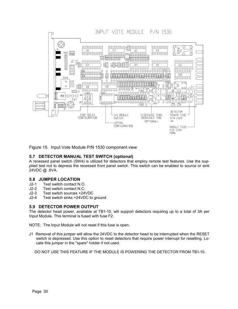
5.7 DETECTOR MANUAL TEST SWITCH (optional) A recessed panel switch (SW4) is utilized for detectors that employ remote test features. Use the sup-plied test rod to depress the recessed front panel switch. This switch can be enabled to source or sink 24VDC @ .8VA.
5.8 JUMPER LOCATION J2-1 Test switch contact N.O. J2-2 Test switch contact N.C. J2-3 Test switch sources +24VDC J2-4 Test switch sinks +24VDC to ground
5.9 DETECTOR POWER OUTPUT The detector head power, available at TB1-10, will support detectors requiring up to a total of 3A per Input Module. This terminal is fused with fuse F2.
NOTE: The Input Module will not reset if this fuse is open.
J1 Removal of this jumper will allow the 24VDC to the detector head to be interrupted when the RESET switch is depressed. Use this option to reset detectors that require power interrupt for resetting. Lo-cate this jumper in the "spare" holder if not used.
DO NOT USE THIS FEATURE IF THE MODULE IS POWERING THE DETECTOR FROM TB1-10.
Figure 15. Input Vote Module P/N 1530 component view
Page 31
5.10 MASTER INPUT VOTE MODULE DIP SWITCH SELECTIONS FIRST ALARM: When the Input Vote Module receives its first alarm via the rear TB1 input terminals, the following functions occur, regardless of DIP switch settings: Alarm Module channel 1(Bell) and channel 3(Strobe) activates {providing the module is utilized}.
VOTED ALARM: When the Input Vote Module satisfies a voting requirement, the following functions si-
multaneously occur.
1. Fire local relay changes state – based on SW1. 2. Alarm Module channel 2 (Horn) activates – based on SW2. 3. Release Module activates – based on SW2 {providing the module is utilized}. SW1-1 OFF - 1st alarm of THIS module activates fire relay. SW1-1 ON - Voted alarm from ANY Master or Slave module(s) activates fire relay. SW1-2 OFF - Fire relay is non-latching. SW1-2 ON - Fire relay is latching. SW2 All four voting switches OFF disables the voting logic. SW2-1 Any Input Vote Module alarm activates voting logic. SW2-2 Any two Input Vote Module alarms activates voting logic. SW2-3 Any three Input Vote Module alarms activates voting logic. SW2-4 Any four or more Input Vote Module alarms activates voting logic.
NOTE: Allow only one switch to be in the “ON” position for SW2.
5.11 SLAVE INPUT MODULE DIP SWITCH SELECTIONS SW1 Same function as Master Input Module. SW2 Same function as Master Input Module EXCEPT voting logic is limited to the fire relay. SW2-5 Locate this switch to the ON position if this is the first left module located in the rack, as viewed
from the front. This switch completes the card removal fault, should any card be removed from the rack.
Sequence of events for all DIP Switch configurations:
1. 1st alarm occurs in any Input Module:
A) The alarm is visually identified on the front panel with the Fire LED that corresponds to the alarm input.
B) Its local fire relay will activate if SW1 is selected for the 1st alarm. C) The Alarm Module channel 1 (Bell) circuit is activated. D) The Alarm Module channel 3 (Strobe) circuit is activated.
2. Voted alarm is satisfied as established by the Master Vote Module, SW2 switch.
A) Its local fire relay will activate if SW1 is selected for the voted alarm. B) The Alarm module channel 2 (Horn) circuit is activated. C) The release module enters its pre-discharge mode and commences timing down.

Page 32
5.12 PANEL TERMINAL STRIP DESIGNATIONS
5.13 INPUT VOTING MODULE PART NUMBER
800-1530-
INPUT MODULE CONDITIONS
TB1# NORMAL ALARM FAULT
1 FIRE 1 INPUT 3.9K RESISTOR NEGATIVE OPEN
2 FIRE 2 INPUT 3.9K RESISTOR NEGATIVE OPEN
3 FIRE RELAY N.C.
4 FIRE RELAY COMMON
5 FIRE RELAY COMMON
6 FIRE RELAY N.O.
7 FIRE 1 OPEN COLLECTOR SINKS 24VDC OPEN COLLECTOR
8 FIRE 2 OPEN COLLECTOR SINKS 24VDC OPEN COLLECTOR
9 DETECTOR TEST OPTION REFER TO JUMPER GUIDE
10 DETECTOR POWER OUT-PUT
REFER TO J1
TB2#
1 PANEL +24VDC INPUT
2 PANEL –24VDC NEGATIVE
3 MODULE REMOTE RESET Momentary +24VDC to reset module
MODULE TYPE TIME DELAY TEST SWITCH
CODE OPTION: CODE OPTION: CODE OPTION:
M MASTER 1 YES 1 YES
S SLAVE 0 NO 0 NO
NOTE: If the 1st alarm is configured to be the voted alarm, all sequences in paragraphs one and two occur simultaneously.
NOTE: The Release Module can be inhibited prior to satisfying the vote logic by placing it into the inhibited mode.
Page 33
6. MANUAL PULL MODULE (800-1441)
Upon closure of a Manual Pull station, the Manual Pull Module FIRE LED will illuminate and the audio and visual appliances will operate through the Alarm Module, if utilized. The Release Module will be initi-ated at this time. The Manual Pull signal is selective at the Release Module program menu to pass through the time delay or bypass the time delay. The option to activate one or two tanks from the Man-ual Pull is also selective at the Release Module program. Refer to Figure 16 for the Manual Pull DIP switch locations.
6.1 INHIBIT This panel switch allows the user to test the audio and visual appliances while disabling the Main and Reserve tanks of the Release Module. All alarms must be clear and panel in normal operating mode to invoke the inhibit function. To activate the inhibit function, depress the inhibit switch on the front panel of the Manual Pull Module. The green power LED will blink to indicate the inhibit mode is valid. The Fault Module will activate until the inhibit mode clears. The Manual Pull can now be tested without affecting the releasing mechanism. The Manual Pull station must be reset before the Manual Pull Module can be reset.
CAUTION: NOTE: The Manual Pull will override an Abort command.
NOTE: Refer to the Release Module switch selections to allow the Manual Pull to release one or
two tanks.
6.2 FAULT ANNUNCIATION An open in the Manual Pull field wiring will illuminate the Yellow Fault LED and sound the audible alarm on the Fault Module. The audible alarm can be silenced while locating the problem.
6.3 TERMINAL STRIP DESIGNATIONS
MANUAL PULL MODULE CONDITIONS
TB1# NORMAL ALARM FAULT
1 MANUAL PULL INPUT 3.9K RESISTOR NEGATIVE OPEN
2 FIRE OUTPUT RELAY COMMON
3 FIRE OUTPUT RELAY N.C.
4 FIRE OUTPUT RELAY N.O.
THE MANUAL PULL INHIBIT SWITCH INHIBITS ONLY THE MANUAL PULL. THE IN-HIBIT FUNCTION LOCATED IN THE RELEASE MODULE DISABLES BOTH MANUAL PULL AND RELEASE MODULE FROM ACTIVATING THE RELEASE SOLENOIDS.

Page 34
Figure 16. Manual Pull Module P/N 1441 component view
6.4 MANUAL PULL DIP SWITCH SELECTIONS
Switch poles must be in the ON position for these functions to operate properly.
ALARM MODULE BELL (channel 1) on Alarm Module will activate. SW1-1 ON
ALARM MODULE HORN (channel 2) on Alarm Module will activate. SW1-2 ON MODULE REMOVAL ALARM SW1-3 ON, only if this module is the first module on the far left side of the rack.

Page 35
7. ALARM MODULE (800-1442) This module is activated by the initiating modules: Gas, Input, or the Manual Pull Module. Once tripped, the configured output of this module will sound a bell / horn and turn on a strobe. The bell / horn can be silenced by depressing the silence switch on the front panel. Any incoming alarms after the Alarm Mod-ule has been silenced will reactivate the audible appliances. When the bell / horn is silenced, the LED referencing that particular audible appliance will blink to indicate there is an audible device that has been silenced. The strobe remains on during an alarm and during the silencing of the audible appliances. Each of the three appliances are fused for 2A of current. All alarms must clear on the initiating modules before the strobe can be reset. Refer to Figure 17 for the DIP switch locations.
7.1 REMOTE BELL / HORN SILENCE The remote bell / horn silence input is an electrical extension to the silence switch located on the front panel of the Alarm Module. The input is normally open and will activate with a momentary close.
7.2 AUXILIARY / REMOTE ALARM INPUT An external input terminal is available for the connection of an auxiliary device that can trip the Alarm Module. This input is connected to negative for normal status and trips the module if a momentary open occurs in the line. Any successive alarms occurring after the audibles have been silenced will reactivate the module. This input must be connected back to negative before the Alarm Module strobe channel can be reset.
7.3 MODULE REMOVAL ALARM If this module is to be located at the left side of the rack, switch SW2-2 must be closed. This switch com-pletes the supervision loop of the Fault Module. Should the Alarm Module be pulled out of the rack, the Fault Module will trip.
7.4 FAULT INDICATION The bell / horn and strobe field wiring are supervised for an open or short in field wiring and will trip their respective fault LED: BELL - FAULT 1, HORN - FAULT 2, STROBE - FAULT 3. This fault is indicated by a steady glow of the yellow LED on the Alarm Module. The fault occurrence will also trip the Fault Mod-ule. The Fault Module can then be silenced while locating the trouble.
7.5 OPTIONAL TEXT OVERLAYS The Alarm Module instructions are based on the text as indicated on Figure 11, module number 1442. The Alarm Module can be supplied with different styles of text on the label, depending on customers’ requirements. The standard label supplied is shown in Figure 11, part number 1442. Note that other styles of labels can accommodate the Alarm Module. To order the proper label, use the following format: 800-1442-XXXX, where XXXX represents the changed label part number. Observe that channel three of the Alarm Module, typically labeled STROBE, cannot be reset until all channels clear. Allestec can also provide custom labels per customer requirements.

Page 36
7.6 ALARM MODULE DIP SWITCH SELECTIONS
Figure 17. Alarm Module P/N 1442 component view
Switch poles must be in the designated position to operate appliances.
AUXILIARY ALARM INPUT (TB1-7) SW1-1 ON will allow the horn circuit to turn on – strobe automatically turns on.
AUXILIARY ALARM INPUT (TB1-7) SW1-2 ON will allow the bell circuit to turn on – strobe automatically turns on.
LOCAL & REMOTE SILENCE (TB1-8) SW2-1 OFF will silence the bell channel and ON will silence the bell and horn channel.
MODULE REMOVAL ALARM SW2-2 ON only if this module is the first module on the left side of the rack.
Page 37
7.7 PANEL TERMINAL STRIP DESIGNATIONS
ALARM MODULE CONDITIONS
TB1# NORMAL ALARM FAULT
1 BELL NEGATIVE 3.9K RESISTOR CHANGE –24V OPEN/SHORT
2 BELL POSITIVE ACROSS #1&2 CHANGE +24V ACROSS #1&2
3 HORN NEGATIVE 3.9K RESISTOR CHANGE –24V OPEN/SHORT
4 HORN POSITIVE ACROSS #3&4 CHANGE +24V ACROSS #3&4
5 STROBE NEGATIVE 3.9K RESISTOR CHANGE –24V OPEN/SHORT
6 STROBE POSITIVE ACROSS #5&6 CHANGE +24V ACROSS #5&6
7 AUXILIARY ALARM CONNECT TO OPEN LINE N/A
AUDIO/VISUAL TRIP NEGATIVE
8 BELL / HORN NORMALLY OPEN
N/A
REMOTE SILENCE

Page 38
8. RELEASE MODULE (800-1443D) The Release Module is activated by the Input or the Manual Pull Module and is designed to support a MAIN and RESERVE solenoid operated suppression tank. This module can also be utilized in a single tank mode. Depending on the occurring events, the module will respond to its pre-selected program in-struction as defined by the user. NOTE: The 800-1443D release module is functionally the same as the previous model 800-1443 release module and can be swapped from the slot. The 800-1443D inhibit feature has changed. The TB1 termi-nals are also identical except for the addition of a discharge relay output. Wire the solenoids to the Release Module as shown in Figure 5. This module may be utilized in a 24 VDC or a single 12 VDC series solenoid mode. Verify that all connections are secure and there is no binding in the field wiring. It is imperative that the inductive kick-back diodes are in place as indi-cated in Figure 5.
CAUTION: 8.1 OPERATING PROCEDURES When the Release Module is first powered or manually reset, all visible LED’s will illuminate for approxi-mately 2 seconds, the audible alarm will beep, then the module display will indicate 00. The quiescent state of the Release Module indicates 00 in the display. No other LED’s should be on. When the Release Module enters into an alarm mode, the display will indicate the time remaining for the MAIN and RESERVE solenoid to energize while the LED indicator will indicate the seconds or minutes remaining. The counting will continue unless the module is interrupted by either the alarm signal deacti-vating from the Input Module (fire extinguished) or an abort function is induced. Once the time delay has expired, the MAIN or RESERVE blinking LED will glow steady indicating an energized solenoid for that specific tank. The user enters the program mode and sets parameters for the MAIN and RESERVE solenoid timing sequence. A pre-discharge time for the MAIN solenoid can be set from .1 to 9.9 minutes. In addition to the MAIN solenoid, a RESERVE timing sequence can also be set from .2 to 9.9 minutes AFTER the MAIN solenoid time has expired. An inhibit (disable) feature allows the initiating and appliance circuits to be tested without activating the solenoid release circuit(s). The inhibit mode cannot be exited unless all alarms are cleared. When the Release Module is entered into the inhibit mode, the Input or Manual Pull Module can be activated into alarm for testing purposes without activating the releasing mechanism. CAUTION:
During an Input Module alarm, a Manual Pull activation will override the Release Module current timing countdown sequence and will discharge the tank in which the time sequence resides, based upon the instant or timed release selection.
DO NOT CONNECT RELEASE SOLENOIDS TO THE SUPPRESSION TANK(S) UNTIL A COMPLETE SYSTEM CHECK OUT HAS BEEN COMPLETED, OR ACCIDENTAL AGENT DISCHARGE MAY OCCUR. IT IS RECOMMENDED THAT ANYTIME THE SYS-TEM IS TESTED THAT THE SOLENOID VALVES ARE TEMPORARILY REMOVED FROM THE TANKS.
LOCATING THE MANUAL PULL MODULE INTO INHIBIT DOES NOT INHIBIT THE RE-LEASE MODULE, ONLY THE MANUAL PULL.

Page 39
The pressure switch is optional and can be disabled if a second extinguishing tank is not utilized. The pressure switch normally closed contact input allows the Release Module to automatically trip the RESERVE solenoid should the MAIN solenoid malfunction. Once the pressure switch has opened, it must remain in that position for at least the first 7 seconds of the RESERVE countdown.
8.2 SOLENOID SPECIFICATION
Solenoids rated at 24 VDC are applicable for installations. The Release Module supervises solenoids with a coil resistance up to 12K ohms and can source 4 amps, continuous. Two 12 VDC solenoids may be connected in series to attain a satisfactory multi-release system.
8.3 PROGRAMMING THE RELEASE MODULE The bold abbreviated characters below are indicated in the display window and represent the functions
as described below. 1. Enter the program mode by depressing the two front panel switches in this sequence. Depress the
Set/Reset button and hold it down. While holding the button down, depress the Step button, then release both of them simultaneously.
2. IH – INHIBIT - The first instruction is the inhibit mode. This is the only menu in the program that the
user can enter and exit from. The panel LED’s will flash and the audible alarm will beep to identify that the module is inhibited. A fault signal will automatically be sent to the fault module to identify that the Release Module is inhibited. The module will remain in fault during the duration of the pro-gramming sequence.
3. PP – PROGRAM PRIMARY (MAIN SOLENOID) – This mode establishes the amount of time lapse from the confirmed activation of an Input or Manual Pull Module to the MAIN solenoid activation. Depress the Step switch until the PP mode is attained. The display will indicate tenths of minutes from .1 minutes (6 seconds) to 9.9 minutes. Increment to the correct time by depressing the Set switch. During an alarm, the display will indicate true seconds for time from 60 to 0 seconds.
4. Pr – PROGRAM (RESERVE SOLENOID) – This mode establishes the amount of time lapse from
the confirmed activation of an Input or Manual Pull Module to the RESERVE solenoid activation. Depress the Step switch until the Pr mode is attained. The display will indicate tenths of minutes from .2 minutes (12 seconds) to 9.9 minutes. Increment to the correct time by depressing the Set switch. During an alarm, the display will indicate true seconds for time from 60 to 0 seconds. NOTE: The time attained for the reserve tank is ADDED to the main solenoid time.
5. PL(0) — MANUAL PULL instant – Depress the Set switch until a zero (0) appears in the display.
The Manual Pull will trip the main solenoid instantly. 6. PL(1) — Manual Pull timed delay – Depress the Set switch until a one (1) appears in the display.
The Manual Pull release will be delayed as programmed by the timing sequence in step 3. 7. AE(0) Abort function not utilized. 8. AE(1) — Abort type 1 – During a MAIN or RESERVE pre-discharge initiated by an Input Module,
pushing the abort switch will automatically add 30 seconds to the timing sequence. This procedure is allowed only once. If the Release Module countdown has temporarily ceased (Input Module not acknowledging a fire), then the abort is activated, the 30 seconds will be added to the existing time delay if there is post ignition fire when the timing continues. NOTE: The 30 seconds that are added will be indicated as seconds as long as the countdown time is 60 seconds or below.
9. AE(2) - Abort type 2 - During a MAIN or RESERVE pre-discharge initiated by an Input Module, if the abort switch is pushed and released before either timer expires, the timing sequence is not modified or interrupted. Pushing the abort switch, then holding it through the end of either timing cycle, then releasing the switch will trip the MAIN or RESERVE solenoid. The solenoid which trips is dependent on which of the timing modes, MAIN or RESERVE, the module is executing. During the time the abort switch is depressed, the current discharge LED will blink at a faster rate when the display descends to 1 second.
10. rE(0) The RESERVE solenoid circuit is disabled. 11. rE(1) The RESERVE solenoid circuit is enabled. This mode requires an inline pressure switch in the
MAIN release discharge circuit as indicated in Figure 5.

Page 40
CAUTION:
8.4 INPUT MODULE ALARM – Receiving an alarm from the Input or Input Vote module There are various sequence of operations that can be executed, depending on the real time status of a fire. The options that are listed below account for when two release tanks are utilized. A. CAUSE
B. EFFECT
C. CAUSE
D. EFFECT
E. CAUSE
F. EFFECT
G. CAUSE
H. EFFECT
The Release Module is activated, the MAIN solenoid timing starts, but the fire is manually extinguished prior to the MAIN cycle time expiring.
The display will start counting down from its pre-selected time until the fire signal expires. The display will then hold (memory feature) the final time remaining until the module is reset. Should the alarm con-tinue, the timing will commence where it left off. The audible alarm remains beeping until the module is reset.
The Release Module is activated, the MAIN solenoid timing starts, the fire remains until the count- down expires and the MAIN solenoid trips, thereby extinguishing the fire. The pressure switch changes state within 7 seconds.
The MAIN agent release is sufficient enough to extinguish the fire and the RESERVE solenoid is never activated. The audible alarm remains beeping until the module is reset.
The Release Module is activated, the MAIN circuit timing starts and counts down to zero, the pressure switch changes state within 7 seconds. The fire is of sufficient magnitude to continue after the MAIN so-lenoid trips.
The display commences its second timing sequence on the RESERVE solenoid and upon the expiration of the timing, the RESERVE solenoid trips. The audible alarm remains beeping until the module is reset.
The Release Module is activated, the MAIN circuit timing starts, the pressure switch does not change state within 7 seconds.
The RESERVE LED and solenoid will automatically turn on, provided the RESERVE solenoid is en-abled. The module display will remain at 00 until reset.
A MANUAL PULL ALARM WILL OVERRIDE AN ABORT FUNCTION AND COMMIT TO THE INSTANT OR DELAYED ACTION AS INDICATED IN THE CONFIGURATION MENU.

Page 41
8.5 MANUAL PULL ALARM DURING PRE-DISCHARGE TIMING – Instant mode PL(1) When there is an Input Module alarm and the Release Module is in a pre-discharge state, if the manual pull is activated, the timing sequence will cease and the current timing window (MAIN or RESERVE) solenoid will activate immediately. If the manual pull occurs in the MAIN countdown, the RESERVE tank will discharge within 7 seconds if the pressure switch malfunctions. If the RESERVE solenoid is dis-abled, then a manual pull in the MAIN countdown will activate only the MAIN solenoid.
NOTE: A P7 appears in the window during the pressure switch transition time. NOTE: A manual pull alarm is committed to its pre-programmed routine once it is activated, and cannot be reset.
8.6 MANUAL PULL ALARM DURING PRE-DISCHARGE TIMING – Time delay mode PL(1) If the manual pull is activated during a pre-discharge alarm, the countdown is then committed to section 8.7, C & D.
8.7 MANUAL PULL ALARM (EXCLUSIVELY) The functions below identify different modes of operation if only the Manual Pull is activated. A. INSTANT RELEASE with RESERVE solenoid disabled – PL(0) rE(0) The MAIN solenoid energizes
on alarm and there is no other action. B. INSTANT RELEASE with reserve tank enabled – PL(0) rE(1) The MAIN solenoid energizes on alarm.
If the pressure switch malfunctions, the RESERVE solenoid will automatically energize within 7 sec-onds. If the pressure switch changes state, the RESERVE tank is retained.
C. TIMED RELEASE with reserve disabled – PL(1) rE(0) After the MAIN time has expired, the MAIN solenoid will energize and end of action.
D. TIMED RELEASE with reserve enabled – PL(1) rE(1) After the MAIN timing has expired, the MAIN solenoid energizes on alarm. If the pressure switch changes state, the RESERVE solenoid will trip at the end of the RESERVE timing sequence. If the pressure switch malfunctions, the RESERVE sole-noid will automatically discharge within 7 seconds.
8.8 INHIBIT (DISABLE MODE) All alarms must be clear and the panel in normal operating (quiescent) mode. The inhibit function will isolate the MAIN and RESERVE solenoids from the Release Module for system testing purposes only. To activate the inhibit function, enter the program mode and remain at the first Step (IH – inhibit). All Release Module LED’s will flash and the audible alarm will pulse to indicate the inhibit mode is valid. The Fault Module will activate until the inhibit mode clears. The system can now be tested without af-fecting the releasing mechanism. The Alarm and Relay Module will activate (if accommodated) as deter-mined by their DIP switch settings. The Release Module cannot be reset until all input alarms have cleared. CAUTION: THE RELEASE MODULE INHIBIT WILL ALSO DISABLE THE MANUAL PULL
MODULE.
8.9 DISCHARGE RELAY The discharge relay is an auxiliary output and is factory programmed to change state when the MAIN solenoid energize occurs. This relay function is a latching feature and can be reset when the module reset button is depressed after alarm(s) have cleared. The alarm relay contact is located at TB1-9&10. Refer to J4 on Figure 18 to select the N.O. or N.C. contact of the relay. This relay can be custom pro-grammed by Allestec to change the current operating status.
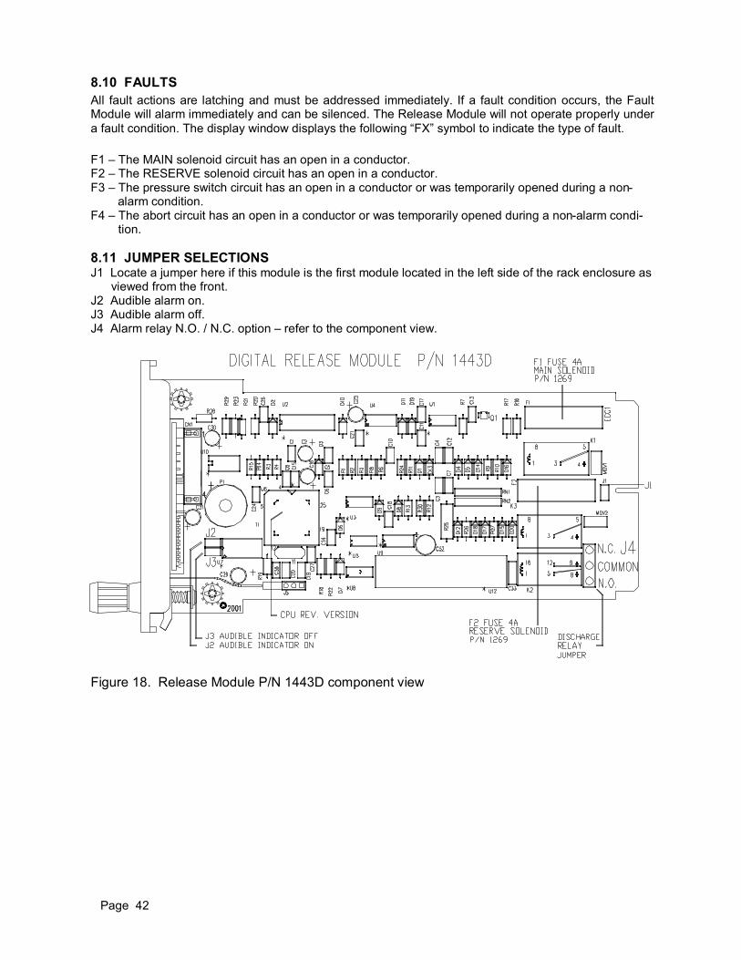
Page 42
8.10 FAULTS
All fault actions are latching and must be addressed immediately. If a fault condition occurs, the Fault Module will alarm immediately and can be silenced. The Release Module will not operate properly under
a fault condition. The display window displays the following “FX” symbol to indicate the type of fault.
F1 – The MAIN solenoid circuit has an open in a conductor. F2 – The RESERVE solenoid circuit has an open in a conductor. F3 – The pressure switch circuit has an open in a conductor or was temporarily opened during a non- alarm condition. F4 – The abort circuit has an open in a conductor or was temporarily opened during a non-alarm condi-
tion.
8.11 JUMPER SELECTIONS J1 Locate a jumper here if this module is the first module located in the left side of the rack enclosure as viewed from the front. J2 Audible alarm on. J3 Audible alarm off. J4 Alarm relay N.O. / N.C. option – refer to the component view.
Figure 18. Release Module P/N 1443D component view

Page 43
8.12 PANEL TERMINAL STRIP DESIGNATIONS
RELEASE MODULE CONDITIONS
TB1# NORMAL ALARM FAULT
1 MAIN SOLENOID POSITIVE SOLENOID SUPERVISED CHANGE +24V OPEN
2 MAIN SOLENOID NEGATIVE SOLENOID SUPERVISED CHANGE –24V OPEN
3 RESERVE SOLENOID POSI-TIVE
SOLENOID SUPERVISED CHANGE +24V OPEN
4 RESERVE SOLENOID NEGA-TIVE
SOLENOID SUPERVISED CHANGE –24V OPEN
5 PRESSURE SWITCH NORMALLY CLOSED OPEN N/A
6 ABORT SUPERVISED INPUT NORMALLY CLOSED OPEN TO ABORT OPEN
7 ABORT OUTPUT TRIGGER 0 VOLTS 24V DURING ALARM @ 5mA
N/A
8 CLOCK SYNC – SPECIAL APPLICATIONS 1Hz PULSE
1Hz DURING ALARM @ 5mA

Page 44
9. WATER MIST (CYCLE) RELEASE MODULE (800-2800) 9.1 APPLICATIONS The model 800-2800 Cycled Release Module (CRM) is utilized in applications that accommodate a wa-ter mist system, conforming to the NFPA 750 standard. This module can be programmed to cycle the mist delivery to obtain maximum effectiveness in fire suppression while utilizing a minimal amount of wa-ter. Applications include industrial electrical equipment, flammable liquid pumping and storage facilities, co-generation power plants, oil refineries, etc.
9.2 OPERATION The CRM is designed to operate in fire systems that utilize non-latching detectors, although, some instal-lations can accommodate latching. The CRM monitors the detector’s fire relay status and determines if a continued mist application is necessary, should the fire persist. Upon receiving a confirmed fire signal from the Input or Manual Pull Module, the pre-discharge timing sequence will commence until its time expires. During this time, the Alarm Module will be initiated while the CRM counts down to initiate its first discharge cycle. The mist solenoid will cycle on and off in a tim-ing sequence pre-programmed by the installer. There is a provision to stipulate the quantity of complete cycles. After the pre-programmed cycle counts have been satisfied, the module will enter into a pause mode, while counting down in tenths of minutes. After the expiration of the pause mode, the CRM will suspend its timing sequences if the fire has been extinguished. If the fire persists, the module will enter into its second timing sequence. The number of timing sequences is determined by the capacity of the water supply. Select a timing sequence that will deplete the water supply should the fire persist.
9.3 INSTALLATION Refer to the field wire diagram on Figure 6 to correctly wire the CRM to the solenoid. Note that the induc-tive kickback diode is required at the location of the solenoid. This diode suppresses the reverse high voltage spike created when the magnetic field around the energized solenoid collapses upon the re-moval of power. Verify this diode is correctly located (reverse polarized) prior to applying power. 9.4 SOLENOID SPECIFICATION Solenoids rated at 24VDC are applicable for installations. The CRM supervises solenoids with a coil re-sistance up to 12K ohms and can source 4 amps, continuous. Two 12VDC solenoids may be connected in series to attain a effective, multi-release system.
9.5 POWER UP Upon application of power, the CRM will display PU (Power-Up) for 5 seconds, while disabling the output relays, then beep and go into the real time display, 00. The 00 will remain in the seven segment displays until an event occurs or the module enters into program mode.
9.6 PROGRAMMING 1. Enter the program mode by depressing the two front panel switches in this sequence. Depress the
Set/Reset button and hold it down. While holding the button down, depress the Step button, then release both of them simultaneously.
2. INHIBIT - The module first enters into the inhibit mode, displaying IH (Inhibit). This is the only menu
in the program the user can enter and exit from. The panel LED’s will flash and the audible alarm will beep to identify that the module is inhibited. A fault signal will automatically be sent to the fault mod-ule to identify that the CRM is inhibited. The CRM will remain in fault during the duration of the pro-gramming sequence.
3. PRE-DISCHARGE - Depress the Step button to the next mode to enter pre-discharge timing. De-press the set button until the correct pre-discharge time is attained. Increment the Set button to set the correct pre-discharge time (0-99 seconds). The pre-discharge LED will remain on during this mode. This mode is primarily utilized for personnel evacuation prior to initiating the mist discharge. If pre-discharge is not required, set the display to 00 seconds.
4. MIST ON - Step to the next function to enter cycle on time by incrementing the Set button until the
correct time is selected. The allowable timeframe for this mode is from 5 to 99 seconds. The Mist Cycle ON LED will remain on during this mode.

Page 45
5. MIST OFF - Step to the next function to enter cycle off time by incrementing the Set button until the correct time is selected. The allowable timeframe for this mode is from 5 to 99 seconds. The Mist cycle OFF LED will remain on during this mode.
6. CYCLE COUNT - Step to the next function to enter cycle number (how many times the on-off se-
quence will occur). Increment the set button until the correct number of cycles are attained, 1 to 9. The display will alternate between the cycle counts and “CC” to identity the program mode. Program only enough cycles to satisfy the retained water capacity.
7. PAUSE MODE - Step to the next function and enter the amount of pause time the module surveys
for fire presence. Depress the Set button to set the correct time, in tenths of minutes. Example: 30 seconds is indicated as .5 (minutes). The pause LED will remain on during this mode. Pause timing may be set from .1 to 9.9 minutes.
8. SAVING PROGRAM DATA - Step to the final function, inhibit, and then exit the program as it was
entered, as described in paragraph one. This mode is the only menu location that allows the user to exit the program, since no data can be altered.
9.7 PROGRAM DATA All program data is stored in nonvolatile memory when the program is exited from the inhibit program location. The module will retain program data even if power is removed.
9.8 INPUT MODULE ALARM The Input Module alarm initiates the CRM timing sequence. All modes will sequentially execute the tim-ing sequences as described in steps 3 through 7.
9.9 MANUAL PULL ALARM A manual pull device wired to the Manual Pull Module, if utilized, can initiate the CRM. If a manual pull occurs, the pre-discharge timing sequence is eliminated and the mist on cycle instantly starts. The tim-ing sequences are identical to the Input Module alarm, as described in steps 3 through 7. If the Manual Pull Module is activated during an Input Module alarm, the pre-discharge timing will be truncated and the module will be committed to its standard timing routine as described in steps 3 through 7.
9.10 INHIBIT (DISABLE) The module can be inhibited by entering into the first program menu to test the fire panel without ener-gizing a solenoid. When in inhibit, the letters IH will be displayed, the panel LED’s will flash, the fault re-lay will energize, the audible alarm will beep, and the Fault Module will initiate. If the CRM receives an alarm from the Input or Manual Pull Module, the program menu will not be able to increment. The sys-tem can be tested while in the inhibit mode without energizing the solenoid relay. The Alarm Module will activate when initiated by the Input or Manual Pull Module and is not influenced by the inhibit.
CAUTION: THE INHIBIT MODE DISABLES THE INPUT MODULE AND THE MANUAL
PULL MODULE.
NOTE: All alarms on the panel must be cleared or the inhibit mode cannot be exited.
9.11 MODULE RESET during an alarm
The CRM can be reset anytime during a timing sequence, either by the front panel reset switch, or by the remote reset input. The application of a temporary +24VDC to terminal TB2-3 will reset the CRM for remote applications. Interrupting the panel power can also reset the module. After resetting the CRM, the current cycle of operation will complete, the module display will alternate between rE (reset) and CX (cycle count). At this point in time, the module can then be reset again to its original status.
NOTE: All Input Module alarm(s) must be cleared for the CRM to reset. The manual pull station(s) and the Manual Pull Module must also be reset.
Page 46
9.12 DETAIL OF CYCLE EVENTS During the mist and pause mode cycles, the display will be interrupted for 2 seconds, at 15-second inter-vals, to identify the current cycle number. This cycle count display will not affect the timing. The audible alarm will beep at a faster rate at this 2 second interval. 9.13 PRE-DISCHARGE The pre-discharge mode will commence the first timing sequence during an alarm. There will be no mist discharge during this time.
9.14 WATER MIST ON Upon expiration of the pre-discharge timing, the display will indicate for two seconds, the current cycle number by displaying CC, CX indicating the current cycle count. After the expiration of the two second cycle number, the display will continue to indicate the pre-programmed timing, in seconds. The mist on LED will illuminate and the associated solenoid will turn on for the timing duration. The audible alarm will beep every second.
9.15 WATER MIST OFF The identical events occur during the mist off event except the mist off LED will turn on and the solenoid will de-energize.
9.16 PAUSE MODE After the pre-programmed quantity of mist on/off cycles have completed, the following events will occur: the module enters into a pause mode, pre selected in tenths of minutes. At the beginning of this cycle, the display will indicate the current cycle number for two seconds. The pause LED will turn on while the display counts down the time remaining.
A. If the fire input signal is gone (fire is extinguished) after the pause time expires, the module dis-play will alternate in two-second intervals: FE, for fire extinguished, and the total amount of cy-cles it took for the fire to be extinguished. The module can now be reset.
B. If the fire remains after the pause mode, the module will remain cycling until 9 cycles have com-pleted. The cycling will continue whether or not the water is still available. When the ninth cycle is attained, the module will remain there, cycling, until the fire alarm has been cleared and the module is reset.
9.17 RELAY FUNCTIONS ALARM RELAY – A dedicated alarm relay energizes during any timing sequence. The relay will revert back to its original status when the timing terminates. The relay is accessed at TB1, terminals 3,4, and 5. SOLENOID RELAY – The solenoid relay will energize only while the mist LED is on. FAULT RELAY – The fault relay will energize and the letters FA will indicate in the display that a fault exists. The relay is accessed at TB1, terminals 6, 7, and 8.
9.18 MODULE FAULTS Faults will be addressed by indicating the letters FA in the module display, tripping the fault relay, and the Fault Module. 1. An open line within the solenoid circuit will induce a latching fault. Should an open circuit occur dur-
ing a cycle discharge, the fault will appear after the module completes the cycling. 2. Depressing the remote reset switch when there is no alarm activity will initiate a non-latching fault. 3. Malfunction fault - Should a malfunction occur and the power fails on the CRM, the Fault Module will indicate a system fault. Locate the problem immediately to restore the panel back to its original operating condition.
9.19 EXTERNAL RESET Connect a normally open switch at contact TB2-3 if a remote reset access is required. One contact of the switch will connect to +24VDC, the other to negative.

Page 47
9.20 INTERNAL CONTROL (option) A connection located at TB1-9 is reserved for an external device to interrogate the cycle function of the CRM. Contact Allestec for more details.
9.21 PLC/CLOCK OUTPUT (option) A connection located at TB1-10 is reserved for an open collector device to monitor the clock sync or real time alarm. Contact Allestec for more details.
9.22 AUDIBLE ALARM Refer to the module diagram to identify the audible alarm jumper. Locate the jumper in J2 to engage the audible alarm or the J3 “spare” jumper to silence it. The audible alarm beeps at the increment of each second of count and at other operational queues.
9.23 MODULE REMOVAL ALARM If this module is to be located at the far- left side of the rack, front view, J1 jumper must be installed. This jumper completes the supervision of the Fault Module. If the CRM is removed from the rack, the Fault Module will trip.
Figure 19. Cycle Release Module P/N 2800 component view

Page 48
10. RELAY MODULE (800-1760) The Relay Module is an alternative method utilized to extend the availability of functions from various other modules within the panel. There are three user relays accessible from the rear of the panel and can be configured from the module. The relays are form C (SPDT) and are rated at 5 amps, 30 VDC or 250 VAC. An audible alarm is provided that has a chirping sound to announce a relay has changed state. The audible alarm can be silenced from the Relay Module front panel. Refer to Figure 6 to identify the terminal strip connections.
10.1 RELAY OUTPUT FUNCTIONS General Alarm The general alarm relay, connections located at TB1-1,2,3, can be configured for latching or non-latching. The general alarm occurs anytime an Input, Input Vote, Manual Pull, or Gas Module receives a first alarm. Depress the front panel silence switch to silence the audible alarm, and the reset switch to reset the module if it has latched. EXCEPTION: If the Manual Pull Module is activated, the general alarm channel will latch, regardless of latch option. The Manual Pull Module must first be reset prior to resetting the Relay Module. Auxiliary Alarm The auxiliary alarm relay, connections located at TB1-4,5,6, can be configured to be tripped from the Input, Input Vote, Manual Pull or Gas Module. This auxiliary relay can also be configured to trip on the Release Module pre-discharge timing sequence. The auxiliary relay can be configured to select none or all of these alarm choices. Fault Alarm The fault alarm relay, connections located at TB1-7,8,9, will trip anytime there is a system fault.
10.2 ALARM ACKNOWLEDGING Whenever the Relay Module LED indicator is on, the associated relay to the LED has changed state. Anytime an alarm occurs, the Relay Module must be silenced and reset separately. Depressing the re-set switch will return any of the three relays to their normal condition as long as there are no latching alarms in the panel to inhibit the reset. NOTE: Once a system event has occurred (General, Auxiliary or Fault Alarm), the specific alarm relay and audible alarm for that event has been committed. Reoccurring alarms for that alarm event channel will not announce unless the module has been reset.
10.3 RELAY MODULE DIP SWITCH SELECTIONS
SYSTEM NOTE: The initiating modules (Input, Input Vote, Manual Pull, Gas Modules) must first be con-figured at their DIP switch locations to properly communicate to the Relay Module. GENERAL ALARM RELAY SW1-3 ON SW1-4 OFF General alarm relay non-latching. SW1-4 ON SW1-3 OFF General alarm relay latching . SW3-1 OFF General alarm relay non-failsafe (de-energized with power on). SW3-1 ON General alarm relay failsafe (energized with power on).

Page 49
10.3 RELAY MODULE DIP SWITCH SELECTIONS (continued)
AUXILIARY ALARM RELAY SW2-1 ON Bell alarm will trip this relay as indicated by the Input, Input Vote, or Gas Module DIP Switch table. SW2-2 ON Horn alarm will trip this relay as indicated by the Input, Input Vote, or Gas Module DIP switch table. SW2-3 ON Manual Pull alarm will trip this relay. SW1-5 ON, SW1-6 OFF Release Module command from Input or Input Vote Module is latching. SW1-6 ON, SW1-5 OFF Release Module command from Input or Input Vote Module is non-latching. SW3-2 OFF Auxiliary alarm relay non-failsafe (de-energized with power on). SW3-2 ON Auxiliary alarm relay failsafe (energized with power on).
FAULT ALARM RELAY SW1-7 ON To activate the fault relay. OFF to disable the relay. SW3-3 OFF Fault alarm relay non-failsafe (de-energized with power on). SW3-3 ON Fault alarm relay failsafe (energized with power on).
MODULE REMOVAL ALARM SW1-1 ON only if this module is the first module on the left side of the rack, as viewed from the front.
AUDIBLE ALARM SW1-2 Switch in the ON position enables the audible device.
NOTE: Manual Pull Alarm - If the Manual Pull is in the inhibit mode, the module will still issue a GENERAL ALARM signal to the Relay Module. However, the alarm signal will be inhibited at location SW2-3 Auxiliary Relay selection.
Figure 20. Relay Module P/N 1760 component view
Page 50
11. FAULT MODULE (800-1444)
A fault in the system will be indicated on the module where the fault originates and will transfer the sig-nal to the Fault Module. The Fault Module will indicate the fault as a system fault and will sound the au-dible alarm. The audible alarm can then be silenced with the front panel reset switch. When the fault problem has been resolved, the system fault LED will then turn off. Refer to section 11.5 for DIP switch selections and Figure 21 for their locations. CAUTION:
11.1 FAULT OUTPUT RELAY The output relay is normally energized for failsafe operation and will change states on any fault condi-tion, including power fail. The relay dry contacts are rated at 5A, 30VDC resistive.
11.2 BATTERY / POWER SUPERVISION A supervisory circuit monitors the DC input power to the system. Should the power rise to approximately 30V or fall to approximately 18V, the Battery Fault indicator will light and the audible alarm will sound. Locate and correct the problem.
11.3 AUXILIARY FAULT INPUT The Auxiliary Fault is a normally closed input circuit that can be utilized to monitor closed contacts. When the line is open, the Fault Module auxiliary fault LED will light. The audible alarm will sound until it is silenced.
11.4 TERMINAL STRIP DESIGNATIONS
FAULT MODULE CONDITIONS
TB1# NORMAL ALARM FAULT
1 FAULT OUTPUT RELAY COMMON
2 FAULT OUTPUT RELAY N.C. POWER OFF
3 FAULT OUTPUT RELAY N.O. POWER OFF
4 AUXILIARY INPUT FAULT NEGATIVE N/A OPEN
BEFORE ATTEMPTING TO CORRECT ANY TROUBLE SIGNAL CONDITION, MAKE SURE THAT THE RELEASE MODULE AND MANUAL PULL MODULE ARE IN THEIR INHIBIT MODE, AND REMOVE THE SOLENOID(S) FROM THEIR RELEASE TANKS TO PROCEED WITH THE DIAGNOSTICS. PROCEED TO INSTALL THE SOLENOIDS, THEN CLEAR THE FAULTS AFTER THE PROBLEM HAS BEEN RESOLVED.

Page 51
11.5 FAULT MODULE DIP SWITCH SELECTIONS
Switch poles must be in the designated position for these functions to operate properly.
AUXILIARY INPUT BYPASSED
SW1-1 ON – Disables the auxiliary input (TB1-4) when there is no connection.
FAULT RELAY OUTPUT SW1-2 ON, SW1-3 OFF — latches the fault relay. SW1-3 ON, SW1-2 OFF — disables fault relay latching.
Figure 21. Fault Module P/N 1444 component view

Page 52
12. ABORT MODULE (800-1436/1437)
Upon activation of the Abort Module, the Module will start to count down from its pre-selected time and stop at zero, unless reset. If both displays are utilized, they will simultaneously start at their pre-selected time. Depending on the style of abort selected from the panel, the timing sequence can be interrupted or started over. Refer to the Release Module sections for more detailed information.
12.1 AUDIBLE ALARM The audible alarm will pulse every second during countdown. Remove J3 jumper if the audible tone is not required. Refer to Figure 22.
12.2 POWER LED This LED will remain on as long as power is applied to unit. Should LED turn off, check that fuse F1 is good and there is power to the module.
12.3 TB1-8 EXTERNAL CLOCK INPUT This terminal connects to an output device whose clock signal will drive the internal clock circuit of the Abort Module. This condition enables exact clock synchronization between the Abort Module and source. Contact Allestec for further details.
12.4 ALLESTEC 800 PANEL CONNECTION Refer to Figure 5 wire diagram.
12.5 CONTROL PANEL BY OTHERS CONNECTION Refer to Figure 8 to connect the Allestec Abort Module to a non - Allestec control panel.
12.6 MOUNTING HOLE DIMENSIONS Refer to Figure 7 to determine mounting hole spacing for the installation of the Abort Module. This mod-ule is designed to be installed in a standard three gang electrical wall box.
12.7 TERMINAL DESIGNATIONS - ALLESTEC ABORT PANEL - Figure 5 1. POWER SUPPLY NEGATIVE 2. POWER SUPPLY POSITIVE 3. TRIGGER (+24V) CONNECT TO RELEASE MODULE TB1-7 4. N.C. CONTACT (PANEL RESET) CONNECT TO RELEASE MODULE TB1-6 5. N.C. CONTACT CONNECT TO NEGATIVE 6. N.C. CONTACT 7. N.C. CONTACT 8. OPTIONAL CLOCK SYNC OPTION
12.8 TERMINAL DESIGNATIONS - PANELS BY OTHERS - Figure 8 1. POWER SUPPLY NEGATIVE 2. POWER SUPPLY POSITIVE 3. TRIGGER (+24V) 4. N.C. CONTACT 5. N.C. CONTACT 6. N.C. CONTACT 7. N.C. CONTACT

Page 53
12.9 TIME COUNTDOWN SETTINGS
Primary Display Board (Figure 22): For systems utilizing a main tank circuit without a reserve tank. The timer can be set to a maximum of 99 seconds by adjusting SW1 and SW2. SW1 on the circuit board cor-responds to the MOST SIGNIFICANT DIGIT and SW2 corresponds to the LEAST SIGNIFICANT DIGIT. Adjust the timer to the same time setting as the panel connected to the Abort Module. Example: If SW1 is set at 2 and SW2 is set at 5, the timing sequence will commence at 25 seconds and count down to zero, unless aborted.
Secondary Display Board - optional (Figure 23): This board is utilized in systems that include a reserve extinguishing tank connected to the panel. The secondary display board clock signal is connected to the primary board, therefore syncing off the same clock circuit. The option display board can be set at a dif-ferent time starting sequence independent of the primary board. SW1 located on the secondary display board is the MOST SIGNIFICANT DIGIT and SW2 is the LEAST SIGNIFICANT DIGIT.
Figure 22. Abort Module P/N 1436 component view
Figure 23. Abort Module P/N 1437 component view

Page 54
13. GAS MODULE REV 5 (800-1457-XXXX)
The NT420 module monitors industrial standard gas detectors 4-20mA output signals. This compact mi-croprocessor module displays a linear representation of the input current as a percent of LFL, PPM or %oxygen. Based on the required input style of gas, refer to the configuration chart in Figure 26. There are three set points that can be set in the program routine for each of the 5 configurations. If a set point is attained during operation, the designated panel alarm LED will illuminate and the associated relay will change state. The operator enters a program mode to establish the operation parameters of the module. Any time the module is in the program mode, the output relays are disabled and the fault circuit is acti-vated. Once data is entered into memory and saved, it will remain until changed, even if power is re-moved from the module. The optional 4-20mA recorder output located on the rear terminal strip is a DC current representation of the input. This output can be connected to a recorder or another style of measuring device. Each module has an external reset input located on the rear terminal strip. A momentary +24V will reset the module if its program flag was set to latch. The rack housing can accommodate up to 16 modules and the user has the option of including other Allestec modules to further enhance the system's operational performance. Other modules that can be added to the system are typically the Alarm Module, for example.
13.1 FIELD WIRE INSTALLATION
CAUTION:
Connect the gas sensors and any field devices to the rear motherboard plane as shown in Figure 5. Af-ter the wires have been connected, route the wires along the rear plane of the panel to their destina-tions. Color coded wires are recommended for ease of identification for installation of the system. The use of stranded copper wire is recommended in lieu of solid strand wire to eliminate the possibility of breaks and loosening of connections. For signaling wires, wire sizes smaller than 20 AWG are not recom-mended, and there will be no more than a total of 5 ohms resistance per each single conductor. For power connections, wire sizes smaller than 16 AWG are not recommended, and there will be no more than 3 ohms total resistance per each power conductor. Refer to Figure 5 for proper field wire connec-tions. CAUTION: SHIELD WIRES MAY BE REQUIRED FOR SENSOR INPUT IF THE ENVIRONMENT IS HEAVILY ENCOMPASSED WITH RF ENERGY.
Power and ground wire gauge must be of sufficient size to ensure that the voltage drop at the maximum current draw of the sensor will not reduce operating voltage to less than the manufacture’s recom-mended operating rating at the sensor. NOTE: Increase the power supply power output if additional devices are connected to the alarm or fault output relays. Observe conditions where the rise of ambient temperature requires power supply derating. Read the power supply specification sheet for more information. Although some applications utilize an Earth grounded power supply, Allestec recommends the power supply be floating. When the rear panel has been wired, verify all connections leading to and from rear panel assembly. Attach the protective acrylic insulator on the standoffs and secure the mounting screws.
OBSERVE REGULATIONS AND MAKE SURE THE AREA IS DECLASSIFIED FOR NON-HAZARDOUS OPERATION BEFORE INSTALLING ANY EQUIPMENT IN HAZARDOUS LOCATIONS.
Page 55
13.2 FIRST MODULE IDENTIFICATION Dip switch SW1-7 must be in the ON position, if this is the first module located on the left hand side of rack assembly, viewed from the front. Refer to Figure 25.
13.3 POWER-UP RESET The Gas Module automatically resets to normal operating parameters when power is first applied or if there is a power interruption. This statement is true, provided the module is within the 4-20mA range after the restoration of power.
13.4 VERSION and CONFIGURATION When the module is powered up, it will temporarily display its release number as rX as well as the con-figuration (C1-C5) that is selected in the variations chart in Figure 25. The module also illuminates all LED’s on power-up.
13.5 PANEL NUMERIC DISPLAY Two seven-segment LED's display the real time concentration of gas level based on the configuration selection in the variations chart. These segment LED's also display the programming information for set-ting parameters of the module.
13.6 PANEL LED's and RELAYS Refer to Figure 24 to identify the threshold LED based on the type of gas utilized. If any alarm LED's are illuminated, their respective relays are energized. If the yellow fail LED is illuminated, the failsafe open collector fault output is de-energized. For gas and toxic monitoring, the HIHI LED is red, HI is red, and Lo is orange. The oxygen has the HI as red, L1 as orange, L2 as red. A yellow LED designates the mod-ule is in a fault or program mode.
13.7 PANEL SWITCHES Two membrane switches located on the front panel control all the menu functions. The STEP and SET/RESET switches are depressed to enter into the program mode. The STEP switch increments the pro-gram steps and the selected values are stored in memory with the SET switch.
13.8 FAULT RESET Any time the module display descends to the under range (ur) point, it will enter the Power Up Reset mode when leaving the under range and initiate the 30 second power-up countdown. If the module fault circuit is flagged for latching and the fault is cleared, depressing the RESET switch will reset the fault circuit and then commence the time delay countdown sequence. NOTE: Fault circuit is set for latching - if the display descends to the under range and back to a normal
operating point, the fault circuit will latch; however, any incoming alarms will still activate the module. Resetting the module will induce the time delay countdown, since there was a fault.

Page 56
13.9 MODULE FRONT VIEWS .
Figure 24. Front panel functions
FIGURE 25. Gas Module P/N 1457 component locations
Viewing window displays real time %LFL, PPM, or %OXYGEN. To enter program mode, depress the SET/RESET switch, hold, depress the STEP switch, then release both switches simultaneously. Three alarm LED’s illuminate when their respective set points have been obtained. Fail LED illuminates if a fault condition occurs.
Label part numbers: P/N 1454 P/N 1489 P/N 1490

Page 57
13.10 PROGRAM FAMILIARITY
Prior to entering the program mode, become familiar with the abbreviated text below. The abbreviated text is sequentially stepped through the numeric display to program the module. The bold letters dis-played to the left are visible on the module numeric LED's. The program instruction set is determined by the location of the J7 and J8 jumper as indicated in Figure 25. PROGRAM INSTRUCTION SET FOR CONFIGURATIONS C1 (Combustible) PG - PROGRAM - momentarily identifies the program mode. AC - ACTUAL CURRENT - displays actual loop current in milliamps for diagnostics. (Program is en-
tered and exited from only here) HH - HIHI (HIGH HIGH) alarm set point. HI - HI (HIGH) alarm set point. LO - LO (LOW) alarm set point. HL - HI LATCH - sets latching feature for high alarm. (see restrictions on section 13.33).
Lo - LOW LATCH - sets latching feature for low alarm. ∟0 = no latch, ∟1 = latch.
FL - FAULT LATCH - sets latching feature for fault. ∟0 = no latch, ∟1 = latch. CL - CALIBRATE LOW - adjusts zero level. CH - CALIBRATE HIGH - adjusts span level. do - DEAD BAND - sets the NT420 not display sensor drift from -3 to +3 of % scale. PROGRAM INSTRUCTION SET FOR CONFIGURATION C2-C4 (H2S in PPM) PG - PROGRAM - momentarily identifies the program mode. AC - ACTUAL CURRENT - displays actual loop current in milliamps for diagnostics. (Program is en-
tered and exited from only here) HH - HIHI (HIGH HIGH) alarm set point. HI - HI (HIGH) alarm set point. Lo - LO (LOW) alarm set point.
HH - HIHI (HIGH HIGH) LATCH - sets latching feature for high alarm. ∟0 = no latch, ∟1 = latch.
HI - HI (HIGH) LATCH - sets latching feature for high alarm. ∟0 = no latch, ∟1 = latch.
LL - LOW LATCH - sets latching feature for low alarm. ∟0 = no latch, ∟1 = latch.
FL - FAULT LATCH - sets latching feature for fault. ∟0 = no latch, ∟1 = latch. CL - CALIBRATE LOW - adjusts zero level. CH - CALIBRATE HIGH - adjusts span level. do - DEAD BAND - sets the NT420 not display sensor drift depending of the configuration style.
PROGRAM INSTRUCTION SET FOR CONFIGURATION C5 (% Oxygen)
PG - PROGRAM - momentarily identifies the program mode. AC - ACTUAL CURRENT - displays actual loop current in milliamps for diagnostics. (Program is en-
tered and exited from only here) HI - HI (HIGH) alarm set point. L1 - LOW alarm set point. L2 - LOW LOW alarm set point.
HI - HI (HIGH) LATCH - sets latching feature for high alarm. ∟0 = no latch, ∟1 = latch.
L1 - LOW LATCH - sets latching feature for low alarm. ∟0 = no latch, ∟1 = latch.
L2 - LOW LOW LATCH - sets latching feature for low low alarm. ∟0 = no latch, ∟1 = latch.
FL - FAULT LATCH - sets latching feature for fault. ∟0 = no latch, ∟1 = latch. CL - CALIBRATE LOW - adjusts zero level. CH - CALIBRATE HIGH - adjusts span level.

Page 58
Type 1
Type 2
Type 3
Type 4
Type 5
Applic
ation
Meth
ane
H2S
H2S
H2S
Oxygen
Sta
rtup indic
ation
C1
C2
C3
C4
C5
Scale
0 t
o 1
00%
0 t
o 1
00 p
pm
0 t
o 5
0 p
pm
0 t
o 2
5 p
pm
0 t
o 2
5%
Model N
um
ber
800-1
457-1
454
800-1
457-1
489
800-1
457-1
489
800-1
457-1
489
800-1
457-1
490
Range
-9%
to 1
00%
-9 p
pm
to 1
00 p
pm
-4 p
pm
to 5
0 p
pm
-2 p
pm
to 2
5 p
pm
-2%
to 2
5%
Range in m
A2.5
mA
to 2
0 m
A2.5
mA
to 2
0 m
A2.5
mA
to 2
0 m
A2.5
mA
to 2
0 m
A2.5
mA
to 2
0 m
A
Calib
ration leve
l50%
50 p
pm
25 p
pm
10 p
pm
21%
Input
mA
at
Span C
alib
ration leve
l12.0
0 m
A12.0
0 m
A12.0
0 m
A10.4
0 m
A17.4
4 m
A
Input
V a
t S
pan C
alib
ration leve
l3.0
00 V
3.0
00 V
3.0
00 V
2.6
00 V
4.3
60 V
Allo
wed r
ange for
Zero
Cal.
3.5
mA
to 4
.5 m
A3.5
mA
to 4
.5 m
A3.5
mA
to 4
.5 m
A3.5
mA
to 4
.5 m
A3.5
mA
to 4
.5 m
A
Allo
wed r
ange for
Span C
al.
10.8
mA
to 1
3.2
mA
10.8
mA
to 1
3.2
mA
10.8
mA
to 1
3.2
mA
9.3
6 m
A t
o 1
1.4
4 m
A15.7
mA
to 1
9.1
8 m
A
Defa
ult H
iHi ala
rm65%
ris
ing
20 p
pm
ris
ing
20 p
pm
ris
ing
20 p
pm
ris
ing
Defa
ult H
i ala
rm55%
ris
ing
15 p
pm
ris
ing
15 p
pm
ris
ing
15 p
pm
ris
ing
24%
ris
ing
Defa
ult L
o a
larm
10%
ris
ing
5 p
pm
ris
ing
5 p
pm
ris
ing
5 p
pm
ris
ing
19%
falli
ng
Defa
ult L
2 a
larm
17%
falli
ng
Defa
ult H
iHi la
tch fla
gO
NO
FF
OF
FO
FF
OF
F
Defa
ult H
i la
tch fla
gO
NO
FF
OF
FO
FF
OF
F
Defa
ult L
o latc
h fla
gO
FF
OF
FO
FF
OF
FO
FF
Defa
ult L
2 latc
h fla
gO
FF
Defa
ult F
ault latc
h fla
gO
FF
OF
FO
FF
OF
FO
FF
Hi cla
mp leve
l lim
itin
g t
o:
60%
unle
ss H
C
jum
per
insta
lled
Lo T
rip leve
l lim
itin
g60%
max.
fixed
60%
max.
fixed
None
None
None
HiH
i Latc
h fla
g p
rogra
mm
able
Sele
cte
d b
y J
um
per
YE
SY
ES
YE
S
Hi Latc
h fla
g p
rogra
mm
able
Sele
cte
d b
y jum
per
YE
SY
ES
YE
SY
ES
Lo L
atc
h fla
g p
rogra
mm
able
YE
SY
ES
YE
SY
ES
YE
S
L2 L
atc
h fla
g p
rogra
mm
able
YE
S
Fault L
atc
h fla
g p
rogra
mm
able
YE
SY
ES
YE
SY
ES
YE
S
"Dis
pla
y Z
ero
" ra
nge (
Dead b
and)
-3 t
o +
3-3
to +
3-3
to +
3-1
to +
1
Under
range c
auses r
esta
rtY
ES
>
-9%
YE
S
> -
9P
PM
YE
S
> -
4P
PM
YE
S
> -
4P
PM
NO
Jum
per
sett
ings
No jum
pers
J7 o
n,
J8 o
ff J7
off,
J8 o
nJ7
on,
J8 o
nju
mp J
7-1
to J
8-1
Model 800-1
457-X
XXX
Gas M
odule
Config
ura
tions (
Rele
ase 5
)
J8J7
J8J7
J8J7
J8J7
J8J7
Figure 26. Configuration table

Page 59
13.11 CONFIGURATION TABLE This chart gives details of what the NT420 module expects as input currents and calibration procedures for gas concentrations. Determine which application is required, and set the jumpers as indicated in Fig-ure 26. NOTE: If the operator changes a jumper configuration and powers up, the module will come up in the AC mode. Exit the program at this point if the module is required to be in its monitoring mode.
13.12 PROGRAM MODE - Entering / Exiting The program mode is easily stepped through to establish the set points, calibrate the module, and flag the relays for latching status. Before entering the program mode, the module is in its normal operating mode, displaying the input data, provided the calibration is within a displaying limit. To enter the program mode, depress and hold the SET/RESET switch, now depress the STEP switch. Release both switches simultaneously. PG or program, will be displayed as long as both switches are depressed. The module is now currently in the program mode. Each mode can be sequentially stepped through by depressing the STEP switch. During the display of the selected mode, the display will alter-nate between the mode and the current selected value. This alternating "mode --> value" display en-ables the operator to identify the function currently active in the program mode, while at the same time selecting the proper values. After the last mode is presented, exit the program in the same sequence as described above at the AC location.
13.13 SELECTING THE LATCHING FEATURE
To set the latching mode, when the user enters the proper program step, the display will alternate be-tween the program step and the latching selection as designated as: ∟0 = no latch, ∟1 = latch. To select the latching feature, depress the SET/RESET switch to alternate between the 0 and 1. CAUTION:
13.14 VIEW DATA To view data stored in the memory, enter the program mode and note that the first mode to display is the AC mode. The STEP switch can be depressed, then released, to scroll through the entire loop. Scrolling through the loop will not affect any established parameters unless the SET/RESET switch is depressed.
13.15 EXITING and SAVING PROGRAM Exiting the program mode is allowed only while the display is in the AC mode. This procedure forces the operator to exit from the AC location since this is the only mode that cannot be modified. Exiting the pro-gram mode will initiate the module power up sequence and display PU (power up) for 5 seconds, then count down the remaining 25 seconds, while remaining in fault. The 25 second count allows for any gas to disperse from the sensor after a calibration has been completed, to prevent false alarms. At this point, any changed values are stored in the non-volatile memory.
NOTE: To cancel the countdown, depress the SET/RESET SWITCH once the display descends to 25.
13.16 DEVIATIONS Should a module require a customer requested deviation, the module will be stamped with the letters DEV followed by a deviation number. Allestec supplies the corresponding S/N data sheet to identify the type of deviation.
THE VALUES ARE ALWAYS "LIVE" WHILE IN THE PROGRAM MODE AND THE OP-ERATOR MUST NOT PRESS THE SET SWITCH UNLESS TO CHANGE THE VALUE. THE AC MODE READING IS ONLY CHANGED BY THE LOOP CURRENT CONNECTED TO THE MODULE.

Page 60
13.17 PROGRAMMING FOR THE C1 COMBUSTIBLE GAS CONFIGURATION C1 13.18 AC MODE Enter the program mode and observe that the first mode is the AC Actual Current mode. This mode is utilized for entering and exiting the program menu. This mode is helpful for diagnosing the 4-20mA loop current because it is an actual current meter. The amount of current that can be displayed is from 00 to 25mA in any of the 5 configurations. The actual real time loop current will display even if the loop current is changing. The calibration or set points of the module have no influence on the AC reading.
13.19 HH (HIHI) SET POINT - Adjusting rising alarms Enter the HIHI alarm mode by depressing the STEP switch. To increment the set point, depress the SET switch and release. The set point digit will increment to the next digit. Depress and hold the SET switch to scan fast through the numeric display. After reaching 99, the display will loop back and commence at the HI set point + 1, preventing the HIHI alarm from equaling or descending below the HI alarm. If a set point for the HIHI alarm is correct below the HI alarm, the HI alarm set point must be lowered. When the correct value has been located, depress the STEP switch and move to the next mode.
13.20 HI SET POINT - Adjusting rising alarms Enter the HI alarm mode by depressing the STEP switch. To increment the set point, depress the SET switch and release. The set point digit will increment to the next digit. Depress and hold the SET switch to scan fast through the numeric display. After reaching 60, the display will loop back and commence at the Lo set point + 1, preventing the HI alarm from equaling or descending below the Lo alarm. If a set point for the HI alarm is correct below the Lo alarm, the Lo alarm set point must be decreased. When the correct value has been located, depress the STEP switch to move to the next mode.
13.21 Lo SET POINT - Adjusting rising alarms Enter the Lo alarm mode by depressing the STEP switch. To increment the set point, depress the SET switch and release. The set point digit will increment to the next digit. Depress and hold the SET switch to scan fast through the numeric display. If the Lo set point equals to or reaches the HI set point, it will loop back to 00. The Lo set point is not allowed to increment above the HI set point. When the correct value has been located, depress the STEP switch to move to the next mode.
13.22 Lo ALARM LATCH The display mode indicates Lo and toggles between ∟0 and ∟1. The latch indication ∟0 = no latch. To
latch the low alarm, depress the SET/RESET switch to change the ∟0 to ∟1.
13.23 FL FAULT LATCH - Fault alarm output The FL will be displayed while in this mode. There are two states to this mode. A 0 in the display indi-cates the fault alarm signal will not latch. A 1 indicates the fault alarm signal will latch. Depress the SET switch to toggle the display to 1. When the correct value has been selected, depress the STEP switch to save the latch mode and to move to the next mode. Anytime the fault circuit is active, the fail LED will illuminate and the fault output will be active. NOTE: During normal display operation, the fault annunciation does not inhibit the display and alarm relays from operating.
13.24 CALIBRATION TECHNIQUE A gas sensor or a current source must be connected to the module to calibrate. The module must also be receiving its current range that represents the low and high scale modes. Before implementing the actual calibration, read through the calibration process below.
Page 61
C1 The following procedures describe two different styles of routine calibrations. The standard calibration requires an operator at the sensor to apply the gas and another operator at the module to perform cali-bration. Remote calibration requires that the module be first calibrated to 4-20mA using a known stan-dard. This calibration allows one operator to apply gas to the sensor and at the same time adjust the remote calibrator at the sensor. If the calibration is difficult to obtain, enter the menu at the AC location to verify that the loop current is close to the 4mA range @ 0% LFL. For standard routine calibration, re-fer to the following procedure. For routine calibration when a remote calibration module is utilized, refer to section 13.28. NOTE:
13.25 STANDARD CALIBRATION
During standard calibration, the module will be in the program mode, disabling all alarm relays. Use a portable gas detector to verify there is no combustible gas present at the sensor.
13.26 CL - CALIBRATE Lo (Zero) 1. Continuing from section 13.23, depress the STEP switch until the CL mode is present. 2. Apply clean or zero air to the sensor per manufacturer’s instructions. 3. On the NT420 depress the SET switch once and the display will zero and indicate 00, provided the
module is reading a valid current range. An Er will be displayed if the input current is above or below an allowable calibration range for the gas module.
13.27 CH - CALIBRATE High (Span) 1. Depress the STEP switch to bring the module to its CH mode. 2. Verify there is gas in the cylinder to sustain the required gas flow for calibration as specified by the
manufacturer. 3. Screw the regulator valve assembly onto the calibration gas cylinder. 4. Connect the gas dispensing adaptor from the gas cylinder hose to the gas sensor as described by
the manufacture. 5. Depress and turn the gas release valve until it locks into the flow position. 6. Allow the gas to flow for time determined by the gas sensor manufacturer. 7. Adjust the display value by depressing the SET switch once on the module until the display indicates
the gas percentage as indicated on the gas cylinder. An Er will be displayed if the input current is above or below an allowable calibration range for the gas module.
8. When the calibration has been completed, turn off the gas; remove the gas dispensing adapter, and then the regulator valve.
9. Depress the STEP switch to loop the program back to the AC mode. 10. Verify that all data that was stored in memory is correct by STEPPING through each mode and
viewing the values with their appropriate input current. (NOTE: CH will display 00 with no gas ap-plied). Continue STEPPING through the program until the AC mode has been obtained.
11. Complete section 13.33 then exit the program mode in the same sequence as described in section 13.12. The time delay will allow the sensor to stabilize while allowing any residual gas in the sensor to dissipate.
12. The module is now displaying the %LFL. NOTE: Standard gas calibration kits are 50% of full scale. Gas concentrations that can accommodate
25% and 10% scales are possible but there is a loss in scale resolution. Please contact Allestec for more information
It is advisable, as described by the gas sensor manufacturers, to let the gas sensor stabilize for some time after applying power. This stabilization period will keep the sensor loop current from drifting after the calibration has been established. This period may take as long as 24 hours.

Page 62
13.28 ALTERNATIVE REMOTE CALIBRATION PREPARATION C1 When a remote calibration system is utilized, the module must be locally calibrated with a 4-20mA stan-dard prior to configuring the remote calibration module. This procedure insures that 0% LFL = 4mA and 100% LFL = 20mA, as perceived by the NT420 module. NOTE: NOTE:
13.29 CL - CALIBRATE Lo (Zero) 1. For set up purpose only, connect a 4-20mA standard to the transmitter input of the module (TB1-8).
There is no transmitter connected at this time. Source 4mA to the module from the standard calibra-tor.
2. Enter the module into its program mode and depress the STEP switch until the CL is obtained. 3. Depress the SET switch on the module once as described in section 13.26-3, until the numeric dis-
play indicates 00 %LFL (Zero).
13.30 CH - CALIBRATE High (Span) 1. Depress the STEP switch to change module to the CH mode. 2. Source 20mA to the module from the calibrator. 3. Depress the SET switch on the module once as indicated in section 13.27-7 until the numeric dis-
play reads 1H% LFL (Span). 4. Verify that all data that was stored in memory is correct by STEPPING through each mode and
viewing the values with their appropriate current. Continue STEPPING through the program until the AC mode has been obtained.
5. The module is now calibrated to accept a remote calibration module. 6. Remove the current source and connect the transmitter to the NT420 Module.
13.31 REMOTE CALIBRATION
CAUTION: CAUTION:
NOTE:
1 Now that the NT420 module is calibrated for a remote calibration module, all further calibrations are performed at the transmitter location. Inserting the remote current meter at the transmitter will shunt the current to the module, inducing a fault condition. Since there is no active current being transmit-ted to the module, the output alarm relays will remain "no change". The alarm relays are NOT dis-abled during this calibration.
2 Follow the manufacturer’s recommended procedure for remote calibration. The remote calibration module will be adjusted for Zero and Span. There is no need to observe any data from the NT420 module during this procedure. After the remote calibration meter is removed, the NT420 will start its 30-second time delay sequence and will then display the %LFL.
Do not enter into the program mode to perform remote calibration. When utilizing a remote cali-bration module, the NT420 module is automatically placed in the fault mode when a third-party current meter is placed in the remote calibration module.
OBSERVE REGULATIONS AND MAKE SURE THE AREA IS DECLASSIFIED PRIOR TO REMOVING ANY EQUIPMENT FROM EXPLOSION PROOF BOXES.
Verify that the NT420 module fault circuit is set for non-latching; otherwise, an operator will be required to reset the module after the remote calibrator is removed.
The NT420 module is factory calibrated for the current range listed above; however, it is rec-ommended that the module calibration be verified before commencing the sensor calibration.
A GROSS ERROR DURING REMOTE CALIBRATION COULD RESULT IN THE ACTI-VATION OF THE ALARM RELAYS. OPERATOR SHOULD TAKE PRECAUTIONS AND DISABLE EQUIPMENT CONNECTED TO THE ALARM RELAYS.

Page 63
13.32 d0 - DISPLAY ZERO (Dead band) C1 The last program instruction is for sensors that could have a minimal drift problem. The module display can be adjusted to not respond to any input current ranges that represent a display change between -3 and +3 and will remain at 00. Depress the SET switch to toggle the d0 to d1. A decimal appears in the display during real time mode to identify that this function is selected. If a set point is selected within this range, it will be acknowledged. Toggle the SET switch to 0 if this function is not correct. Review section 13.12 to exit program.
13.33 ALARM SET POINTS - C1 only - Agency Restrictions Some agency requirements state that the HI alarm cannot rise above 60% LFL and must be latching. There are modifications that can be made to circumvent these restrictions. This modification can be util-ized on applications requiring flow indication or similar requirements. The power must be turned off and the module removed to make these modifications. After power is applied to the module, new data can then be programmed. Place a check mark in the appropriate box below to identify a logic change. Refer to Figure 25 to identify the location of jumpers to install, thereby removing set point restrictions. [ ] [ ]
NOTE: It is recommended that the above alarms remain latching unless their corresponding relays are connected to an auxiliary system that accomplishes and reports the same latching feature.
[ ]
HHL Jumper - HIHI alarm Latch. The HIHI alarm is normally configured to latch. Install a jumper to allow the HIHI alarm NOT to latch. There is no change in the program display.
HL Jumper - HI alarm Latch. The HI alarm is normally configured to latch. Install a jumper to re-move the HI alarm forced latch. When this jumper is installed, the HL mode will appear in the pro- gram display and will allow the operator the choice to latch or not to latch the HI alarm through the program menu. A 00 in the display indicates the HI alarm relay will not latch. A 01 indicates the HI alarm relay will latch.
HC Jumper - HI alarm Clamp. Install a jumper to allow the HI alarm to rise above 60% LFL. There is no change in the program display.

Page 64
13.34 PROGRAMMING FOR THE C2- C4 H2S GAS CONFIGURATION 13.35 INTRODUCTION Based on the calibration gas concentration utilized to calibrate the system, determine which configuration from Figure 26 to refer to for additional information. Start at the beginning of the C1 section to program the NT420 for the C2-C4 options. Then review the configuration chart in Figure 26 to determine where the additional program steps below are included in the instruc-tion set. After entering the set point and latching options, proceed to the calibration procedures and final instructions of chapter 13. 13.36 HH (HIGH HIGH) ALARM LATCHING Select the HIGH HIGH alarm to latch by toggling between ∟0 and ∟1. The latch indication ∟0 = no
latch. To latch the HH alarm depress the SET/RESET switch to change the ∟0 to ∟1.
13.37 HI (HIGH) ALARM LATCHING Select the HIGH alarm to latch by toggling between ∟0 and ∟1. The latch indication ∟0 = no latch. To
latch the HI alarm depress the SET/RESET switch to change the ∟0 to ∟1
13.38 Lo (LOW) ALARM LATCHING Select the Lo alarm to latch by toggling between ∟0 and ∟1. The latch indication ∟0 = no latch. To latch
the Lo alarm depress the SET/RESET switch to change the ∟0 to ∟1.
NOTE: It is recommended that the above three alarms remain latching unless their corresponding relays are connected to an auxiliary system that accomplishes and reports the same latching feature.
13.39 VIEWING DISPLAY FRACTIONAL INTEGERS (C4 CONFIGURATION) When the controller is in its quiescent mode indicating the gas level, depress the STEP button when the display value is 10 or more to indicate the value to the right of the decimal.

Page 65
13.40 PROGRAMMING THE OXYGEN GAS CONFIGURATION C5 13.41 INTRODUCTION This section describes addition instructions that are in the program mode to properly set up the controller for measuring oxygen. Start at the beginning of the C1 section to program the NT420 for the C5 options. Then review the configuration chart in Figure 26 to determine where the additional program steps below are included in the instruction set. After entering the set point and latching options, proceed to the calibration procedures and final instructions of this chap-ter. 13.42 SET POINT THRESHOLD LEVELS The NT420 controller allows two set points for oxygen deficiency, (falling) L1 and the lowest level, L2. The HI (high) level indicates rising oxygen (enrichment). Under normal oxygen at-mosphere levels the controller will be indicating the percent of oxygen %O2 between the HI and L1 levels. Any levels of oxygen increasing or decreasing beyond the threshold will trip that channel and its associated relay. Refer to Figure 24 to become familiar with the controller front panel layout. The NT420 controller accommodates industrial standard 4-20mA inputs.
NOTE: The NT420 comes with the jumper, J7 & J8 properly inserted when ordering for oxygen applica-tions.
13.43 HI (HIGH) SET POINT - Adjusting rising alarms Select a threshold for a rising alarm, if utilized, for oxygen enrichment. This threshold must be between the HI and L2 alarm level.
13.44 L1 SET POINT - Adjusting falling alarms Select a threshold for a falling alarm on oxygen deficiency. This threshold must be between the HI and L2 alarm level.
13.45 L2 SET POINT - Adjusting falling alarms Select a threshold for a second falling alarm on oxygen deficiency. This threshold must be be-low the L1 alarm level. WARNING: DO NOT SET THE L2 BELOW 18%
13.46 HI (HIGH) ALARM LATCHING Select the HIGH alarm to latch by toggling between ∟0 and ∟1. The latch indication ∟0 = no latch. To
latch the HI alarm depress the SET/RESET switch to change the ∟0 to ∟1.
13.47 L1 (LOW 1) ALARM LATCHING Select the L1 alarm to latch by toggling between ∟0 and ∟1. The latch indication ∟0 = no latch. To latch
the L1 alarm depress the SET/RESET switch to change the ∟0 to ∟1.
13.48 L2 (LOW 2) ALARM LATCHING Select the L2 alarm to latch by toggling between ∟0 and ∟1. The latch indication ∟0 = no latch. To latch
the L2 alarm depress the SET/RESET switch to change the ∟0 to ∟1. NOTE: It is recommended that the above three alarms remain latching unless their corresponding
relays are connected to an auxiliary system that accomplishes and reports the same latching feature.
13.49 VIEWING DISPLAY FRACTIONAL INTEGERS When the controller is in its quiescent mode indicating the gas level, depress the STEP button when the display value is 10 or more to indicate the value to the right of the decimal.

Page 66
13.50 RELAY OUTPUT SELECTIONS FOR C1 THROUGH C4 CONFIGURATIONS
Each of the three alarm set points are connected to an output relay. The relays will energize when their respective LED set point is activated. The relay outputs can be adjusted for normally open or normally closed. Refer to Figure 25 to establish relay output configurations. The relays are rated 5A, 30VDC re-sistive; 250VAC. J1 through J6 are jumpers to accommodate heavy relay current capacity and it is imperative that each jumper mating connector correlates to its respective mating pin. The NT420 will trip the alarm output relays as specified below.
13.51 ALARM MODULE COMMUNICATION (P/N 1442) C1-C4
Refer to the table below to allow communication between the NT420 and the Alarm Module. Locate the DIP switch SW1 on the module to select the proper function. When the NT420 enters into an alarm threshold, the corresponding Alarm Module channel will enter into alarm based on the tables below. NOTE: Switch ON only the correct set point function to activate the Alarm Module. All unused switch
selections will remain in the OFF position. The STROBE circuit (channel 3) of the Alarm Module automatically turns on with the activation of the Lo alarm of the NT420 module.
HIHI alarm N.C. J1 HI alarm N.C. J3 Lo alarm N.C. J5
HIHI alarm N.O. J2 HI alarm N.O. J4 Lo alarm N.O. J6
SW1 ON #1 #2 #3 SWITCH POSITIONS
Select one set point switch which will activate the Alarm Module BELL circuit (Channel 1).
HH HI LO ALARM THRESHOLD
SW1 ON #4 #5 #6 SWITCH POSITIONS
Select one set point switch which will activate the Alarm Module HORN circuit (Channel 2).
HH HI LO ALARM THRESHOLD

Page 67
13.52 RELAY OUTPUT SELECTION FOR C5 OXYGEN CONFIGURATION (continued) Each of the three alarm set points are connected to an output relay. The relays will energize when their respective LED set point is activated. The relay outputs can be adjusted for normally open or normally closed. Refer to Figure 25 to establish relay output configurations. The relays are rated 5A, 30VDC re-sistive; 250VAC. J1 through J6 are jumpers to accommodate heavy relay current capacity and it is imperative that each jumper mating connector correlates to its respective mating pin. The NT420 will trip the alarm output relays as specified below.
13.53 ALARM MODULE COMMUNICATION (P/N 1442) C5
Refer to the table below to allow communication between the NT420 and the Alarm Module. Locate the DIP switch SW1 on the module to select the proper function. When the NT420 enters into an alarm threshold, the corresponding Alarm Module channel will enter into alarm based on the tables below. NOTE: Switch ON only the correct set point function to activate the Alarm Module. All unused switch
selections will remain in the OFF position. The STROBE circuit (channel 3) of the Alarm Module automatically turns on with the activation of the L1 alarm of the NT420 module.
HI alarm N.C. J1 L1 low alarm N.C. J3 L2 low alarm N.C. J5
HI alarm N.O. J2 L1 low alarm N.O. J4 L2 low alarm N.O. J6
SW1 ON #1 #2 #3 SWITCH POSITIONS
Select one set point which will activate the Alarm Module BELL circuit (Channel 1).
HI L1 L2 ALARM THRESHOLD
SW1 ON #4 #5 #6 SWITCH POSITIONS
Select one set point which will activate the Alarm Module HORN circuit (Channel 2).
HI L1 L2 ALARM THRESHOLD

Page 68
13.54 FAULT ANNUNCIATION There are numerous conditions that determine if a fault is to be addressed. In any given circumstance below, the module will remain in the fail mode as long as the fault remains. Unless the module is in its program mode, the visual indication that a fault exists is evident by the yellow fault LED. Depress the reset switch to reset the module after the fault has been eliminated, if the fault status is latching.
13.55 INDUCED FAULTS 1. Initial power application of the module for the first 30 seconds. 2. Entering or exiting the program mode. 3. If the display enters into its over current range, OC. 4. If the display enters into its under range, ur.
13.56 MALFUNCTION FAULTS
1. Defective module, transmitter, or sensor. 2. Improper wired transmitter. 3. No transmitter. 4. No sensor. 5. Open circuit in sensor or wiring. 6. Sensor output power fuse blows on the NT420 and loses power. 7. An internal microprocessor error. This error would be indicated in the display as a numeric "EP".
Should this fault ever happen, remove power for 10 seconds and then apply power to the unit. If the problem remains, contact the factory.
13.57 TERMINAL BLOCK DESIGNATIONS Refer to Figure 5.
13.58 REMOTE RESET The remote reset located at TB2-3 will reset the module when a momentary +24VDC is applied here. Each module can be individually reset unless their reset inputs are connected together.
13.59 FAULT EXTERNAL OUTPUT The NT420 provides a transistor output where the collector is connected to the rear terminal strip. Dur-ing normal operation, the open collector located at TB1-7 can sink up to 24 volts at 1 amp. This is a fail-safe current sink and can be connected to a relay coil if required. Should a fault occur, the collector will float. This output is floating anytime the fault LED on the front panel is on. Refer to Figure 5 for wiring information.
13.60 RECORDER OUTPUT (optional) Terminal TB1-10 can be utilize to connect a recorder or similar measuring device. The buffered output of this terminal is an exact duplication of the input loop current and is unaffected by the module calibration.
13.61 PART NUMBER INFORMATION
PART NUMBER DESCRIPTION
800-1457-1454 NT420 Combustible gas detection module, %LFL
800-1457-1489 NT420 Toxic gas detection module, PPM
800-1457-1490 NT420 Oxygen gas detection module, %OXYGEN

Page 69
14. APPROVED DETECTOR AND APPLIANCE COMPONENTS Components that carry the Factory Mutual approval are approved by Allestec for connecting to the 800 panel. The user must identify such components and connect them as described in the context of this manual. The components’ operational specifications must fall within the Allestec module specification window to be utilized correctly. There will be no exceptions for voltages, currents, or loads that may deviate from the specifications as defined in this manual. Should there be any questions pertaining to the installation of components, please contact Allestec prior to installation.
15. MAINTENANCE Preventative maintenance should be performed within the requirements of NFPA 72 and in accordance with local and State codes. The final decision making on preventative maintenance should be the local authority having jurisdiction on the system.
DATE TESTED COMMENTS INITIALS

Page 70
16. WARRANTY Allestec Corporation warrants the module parts and labor for three years from date stamped on the printed circuit board. Allestec identifies each module by their unique serial number. Allestec will repair any module found by us to be defective in workmanship or materials. This warranty does not apply to any part or product that has been subjected to misuse, improper installation, or any type of alterations. There are no implied warranties of merchantability, fitness or other implied warranties or representations for any of Allestec's products except the warranty specified herein. In no event shall Allestec be liable for any consequential, special or other damages attributable to our product except as specified herein. The foregoing obligations are in lieu of all other obligations and liabilities including negligence, and of all war-ranties of merchantability or fitness for a particular purpose or otherwise, express, or implied, in fact or in law, and state Allestec's entire and exclusive liability and buyer's exclusive remedy for any claim of dam-ages in connection with the sale or furnishing of the products, their design, suitability for use, installation, or operation. Buyer is solely responsible for the proper installation, maintenance and use of the mod-ules, and Allestec will in no event be liable for any special, incidental or consequential damages whatso-ever.