Embed Size (px)
Citation preview
Industrial Generator Sets
Models:
10-1000 kWController:
APM402/Decision-Makerr 3000
TP-6694 7/19l
Operation
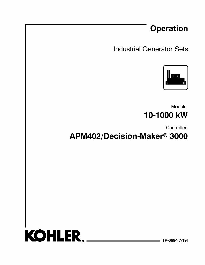
WARNING: This product can expose youto chemicals, including carbon monoxideand benzene, which are known to the Stateof California to cause cancer and birthdefects or other reproductive harm.For more information go towww.P65warnings.ca.gov
WARNING: Breathing diesel engineexhaust exposes you to chemicals known tothe State of California to cause cancer andbirth defects or other reproductive harm.S Always start and operate the engine ina well-ventilated area.
S If in an enclosed area, vent the exhaustto the outside.
S Do not modify or tamper with theexhaust system.
S Do not idle the engine except asnecessary.
For more information go towww.P65warnings.ca.gov/diesel
Product Identification Information
Product identification numbers determine service parts.Record the product identification numbers in the spacesbelow immediately after unpacking the products so thatthe numbers are readily available for future reference.Record field-installed kit numbers after installing thekits.
Generator Set Identification NumbersRecord the product identification numbers from thegenerator set nameplate(s).
Model Designation
Specification Number
Serial Number
Accessory Number Accessory Description
Engine IdentificationRecord the product identification information from theengine nameplate.
Manufacturer
Model Designation
Serial Number
Controller IdentificationRecord the controller description from the generator setoperation manual, spec sheet, or sales invoice. Recordthe Controller Serial Number from the controllernameplate.
Controller DescriptionAPM402/Decision-Makerr 3000
Controller Serial Number
Firmware/Software Version NumbersRecord the version and reference numbers as shippedfrom the manufacturer. Determine the ApplicationProgram Version Number as shown in Menu 20.Determine the Personality Profile Reference Numberfrom the disk supplied with the literature packet.
Application Program Version Number
Personality Profile Reference Number
User Parameter File Reference Number
Version Number Upgrades/UpdatesRecord the version number upgrade/updates wheninstalled.
Version No./Date Installed
Software OptionsRecord the software options.
Number and Description
Table of Contents
TP-6694 7/19 Table of Contents 3
Product Identification Information 2. . . . . . . . . . . . . . . . . . . . . . . . . . . . . . . . . . . . . . . . . . . . . . . . . . . . . . . . . .
Safety Precautions and Instructions 7. . . . . . . . . . . . . . . . . . . . . . . . . . . . . . . . . . . . . . . . . . . . . . . . . . . . . . . .
Introduction 13. . . . . . . . . . . . . . . . . . . . . . . . . . . . . . . . . . . . . . . . . . . . . . . . . . . . . . . . . . . . . . . . . . . . . . . . . . . . . .Abbreviations 13. . . . . . . . . . . . . . . . . . . . . . . . . . . . . . . . . . . . . . . . . . . . . . . . . . . . . . . . . . . . . .SiteTecht Software 13. . . . . . . . . . . . . . . . . . . . . . . . . . . . . . . . . . . . . . . . . . . . . . . . . . . . . . . . . .List of Related Materials 13. . . . . . . . . . . . . . . . . . . . . . . . . . . . . . . . . . . . . . . . . . . . . . . . . . . . .
Service Assistance 14. . . . . . . . . . . . . . . . . . . . . . . . . . . . . . . . . . . . . . . . . . . . . . . . . . . . . . . . . . . . . . . . . . . . . . . .
Section 1 Specifications and Features 15. . . . . . . . . . . . . . . . . . . . . . . . . . . . . . . . . . . . . . . . . . . . . . . . . . . . . .1.1 Introduction 15. . . . . . . . . . . . . . . . . . . . . . . . . . . . . . . . . . . . . . . . . . . . . . . . . . . . . . . . . .1.2 Controller Features 15. . . . . . . . . . . . . . . . . . . . . . . . . . . . . . . . . . . . . . . . . . . . . . . . . . . .
1.2.1 Switches and Controls 16. . . . . . . . . . . . . . . . . . . . . . . . . . . . . . . . . . . . . . . . .1.2.2 Annunciator Lamps 16. . . . . . . . . . . . . . . . . . . . . . . . . . . . . . . . . . . . . . . . . . . .1.2.3 Digital Display 18. . . . . . . . . . . . . . . . . . . . . . . . . . . . . . . . . . . . . . . . . . . . . . . .1.2.4 Controller Fault Diagnostics 23. . . . . . . . . . . . . . . . . . . . . . . . . . . . . . . . . . . .1.2.5 Digital Display Circuit Board and Connections 25. . . . . . . . . . . . . . . . . . . . .1.2.6 Main Logic Circuit Board 25. . . . . . . . . . . . . . . . . . . . . . . . . . . . . . . . . . . . . . .1.2.7 Terminal Jumper 26. . . . . . . . . . . . . . . . . . . . . . . . . . . . . . . . . . . . . . . . . . . . . .1.2.8 Communication Ports 26. . . . . . . . . . . . . . . . . . . . . . . . . . . . . . . . . . . . . . . . . .1.2.9 Fuses 26. . . . . . . . . . . . . . . . . . . . . . . . . . . . . . . . . . . . . . . . . . . . . . . . . . . . . . .
1.3 Controller Logic Specifications 27. . . . . . . . . . . . . . . . . . . . . . . . . . . . . . . . . . . . . . . . . .1.3.1 Status Event and Fault Specifications 27. . . . . . . . . . . . . . . . . . . . . . . . . . . .1.3.2 Voltage Regulator and Calibration Specifications 33. . . . . . . . . . . . . . . . . .1.3.3 Voltage Regulator Adjustments 33. . . . . . . . . . . . . . . . . . . . . . . . . . . . . . . . .
Section 2 Operation 35. . . . . . . . . . . . . . . . . . . . . . . . . . . . . . . . . . . . . . . . . . . . . . . . . . . . . . . . . . . . . . . . . . . . . . .2.1 Prestart Checklist 35. . . . . . . . . . . . . . . . . . . . . . . . . . . . . . . . . . . . . . . . . . . . . . . . . . . . .2.2 Exercising Generator Set 35. . . . . . . . . . . . . . . . . . . . . . . . . . . . . . . . . . . . . . . . . . . . . .2.3 Operation in Cold Weather Climates 36. . . . . . . . . . . . . . . . . . . . . . . . . . . . . . . . . . . . .2.4 Controller Operation 36. . . . . . . . . . . . . . . . . . . . . . . . . . . . . . . . . . . . . . . . . . . . . . . . . . .
2.4.1 Starting 36. . . . . . . . . . . . . . . . . . . . . . . . . . . . . . . . . . . . . . . . . . . . . . . . . . . . . .2.4.2 Stopping (User Stopping and Fault Shutdown) 37. . . . . . . . . . . . . . . . . . . .2.4.3 Emergency Stop Switch Resetting 37. . . . . . . . . . . . . . . . . . . . . . . . . . . . . . .2.4.4 System Status Lamps 38. . . . . . . . . . . . . . . . . . . . . . . . . . . . . . . . . . . . . . . . .2.4.5 System Fault Warning Lamp with Digital Displays 38. . . . . . . . . . . . . . . . . .2.4.6 System Fault Shutdown Lamp With Digital Displays 40. . . . . . . . . . . . . . . .2.4.7 Status and Notice Digital Displays 43. . . . . . . . . . . . . . . . . . . . . . . . . . . . . . .2.4.8 Controller Resetting (Following System Shutdown or Warning) 45. . . . . .2.4.9 Powering Up the Engine Control Module (ECM) 45. . . . . . . . . . . . . . . . . . .
2.5 Menu Displays 46. . . . . . . . . . . . . . . . . . . . . . . . . . . . . . . . . . . . . . . . . . . . . . . . . . . . . . . .2.6 Monitoring and Programming Setup 49. . . . . . . . . . . . . . . . . . . . . . . . . . . . . . . . . . . . .
2.6.1 PC Communications 49. . . . . . . . . . . . . . . . . . . . . . . . . . . . . . . . . . . . . . . . . . .2.6.2 Modbusr Communications 49. . . . . . . . . . . . . . . . . . . . . . . . . . . . . . . . . . . . . .
2.7 Reviewing Menu Displays 50. . . . . . . . . . . . . . . . . . . . . . . . . . . . . . . . . . . . . . . . . . . . . .2.7.1 Error Messages 51. . . . . . . . . . . . . . . . . . . . . . . . . . . . . . . . . . . . . . . . . . . . . . .2.7.2 Overview 52. . . . . . . . . . . . . . . . . . . . . . . . . . . . . . . . . . . . . . . . . . . . . . . . . . . .2.7.3 Engine Metering 52. . . . . . . . . . . . . . . . . . . . . . . . . . . . . . . . . . . . . . . . . . . . . .2.7.4 Generator Metering (and Calibration) 53. . . . . . . . . . . . . . . . . . . . . . . . . . . .2.7.5 GenSet Information 54. . . . . . . . . . . . . . . . . . . . . . . . . . . . . . . . . . . . . . . . . . . .2.7.6 GenSet Run Time 54. . . . . . . . . . . . . . . . . . . . . . . . . . . . . . . . . . . . . . . . . . . . .2.7.7 GenSet System 54. . . . . . . . . . . . . . . . . . . . . . . . . . . . . . . . . . . . . . . . . . . . . . .2.7.8 GenSet Calibration 56. . . . . . . . . . . . . . . . . . . . . . . . . . . . . . . . . . . . . . . . . . . .2.7.9 Voltage Regulator 57. . . . . . . . . . . . . . . . . . . . . . . . . . . . . . . . . . . . . . . . . . . . .2.7.10 Digital Inputs 58. . . . . . . . . . . . . . . . . . . . . . . . . . . . . . . . . . . . . . . . . . . . . . . . .2.7.11 Digital Outputs 59. . . . . . . . . . . . . . . . . . . . . . . . . . . . . . . . . . . . . . . . . . . . . . . .2.7.12 Analog Inputs 60. . . . . . . . . . . . . . . . . . . . . . . . . . . . . . . . . . . . . . . . . . . . . . . . .
Table of Contents, continued
TP-6694 7/19Table of Contents4
2.7.13 Battery Charger 1 and 2 61. . . . . . . . . . . . . . . . . . . . . . . . . . . . . . . . . . . . . . . .2.7.14 Event Log 62. . . . . . . . . . . . . . . . . . . . . . . . . . . . . . . . . . . . . . . . . . . . . . . . . . . .2.7.15 Volt Select 62. . . . . . . . . . . . . . . . . . . . . . . . . . . . . . . . . . . . . . . . . . . . . . . . . . .
Section 3 Scheduled Maintenance 63. . . . . . . . . . . . . . . . . . . . . . . . . . . . . . . . . . . . . . . . . . . . . . . . . . . . . . . . . .3.1 Alternator Service 63. . . . . . . . . . . . . . . . . . . . . . . . . . . . . . . . . . . . . . . . . . . . . . . . . . . . .3.2 Engine Service 63. . . . . . . . . . . . . . . . . . . . . . . . . . . . . . . . . . . . . . . . . . . . . . . . . . . . . . .3.3 Service Schedule 64. . . . . . . . . . . . . . . . . . . . . . . . . . . . . . . . . . . . . . . . . . . . . . . . . . . . .3.4 Alternator Bearing Service 66. . . . . . . . . . . . . . . . . . . . . . . . . . . . . . . . . . . . . . . . . . . . .
3.4.1 20- 300 kW Models 66. . . . . . . . . . . . . . . . . . . . . . . . . . . . . . . . . . . . . . . . . . . .3.4.2 300- 1000 kW Models with 4M/5M/7M Single-Bearing Alternator 66. . . . .
3.5 Diesel Fuel Systems 66. . . . . . . . . . . . . . . . . . . . . . . . . . . . . . . . . . . . . . . . . . . . . . . . . . .3.5.1 Bleeding Air from Fuel System 66. . . . . . . . . . . . . . . . . . . . . . . . . . . . . . . . . .
3.6 Gaseous Fuel Systems 67. . . . . . . . . . . . . . . . . . . . . . . . . . . . . . . . . . . . . . . . . . . . . . . .3.6.1 Gaseous Fuel System Concept
(Single Fuel) 67. . . . . . . . . . . . . . . . . . . . . . . . . . . . . . . . . . . . . . . . . . . . . . . . .3.6.2 LPG Liquid Withdrawal Fuel System Concept 67. . . . . . . . . . . . . . . . . . . . .3.6.3 Natural Gas and LPG Conversion 68. . . . . . . . . . . . . . . . . . . . . . . . . . . . . . .3.6.4 Fuel System Changeover Kits (Dual Fuel) 68. . . . . . . . . . . . . . . . . . . . . . . .3.6.5 Fuel Conversion Connections 68. . . . . . . . . . . . . . . . . . . . . . . . . . . . . . . . . . .
3.7 Crankcase Ventilation (CCV) Heater Kit GM78171-KP1 73. . . . . . . . . . . . . . . . . . . .3.8 Air Cleaner Restrictor Indicator (if equipped) 73. . . . . . . . . . . . . . . . . . . . . . . . . . . . . .3.9 Cooling System 73. . . . . . . . . . . . . . . . . . . . . . . . . . . . . . . . . . . . . . . . . . . . . . . . . . . . . . .
3.9.1 Coolant Level Check 73. . . . . . . . . . . . . . . . . . . . . . . . . . . . . . . . . . . . . . . . . .3.9.2 Cooling System Component Inspection 74. . . . . . . . . . . . . . . . . . . . . . . . . .3.9.3 Procedure to Drain Cooling System 75. . . . . . . . . . . . . . . . . . . . . . . . . . . . . .3.9.4 Procedure to Flush and Clean Cooling System 75. . . . . . . . . . . . . . . . . . . .3.9.5 Procedure to Refill Cooling System 75. . . . . . . . . . . . . . . . . . . . . . . . . . . . . .
3.10 Battery 76. . . . . . . . . . . . . . . . . . . . . . . . . . . . . . . . . . . . . . . . . . . . . . . . . . . . . . . . . . . . . .3.10.1 Clean Battery 77. . . . . . . . . . . . . . . . . . . . . . . . . . . . . . . . . . . . . . . . . . . . . . . . .3.10.2 Electrolyte Level Inspection 77. . . . . . . . . . . . . . . . . . . . . . . . . . . . . . . . . . . . .3.10.3 Specific Gravity Check 77. . . . . . . . . . . . . . . . . . . . . . . . . . . . . . . . . . . . . . . . .3.10.4 Charge Battery 78. . . . . . . . . . . . . . . . . . . . . . . . . . . . . . . . . . . . . . . . . . . . . . .
3.11 Storage Procedure 78. . . . . . . . . . . . . . . . . . . . . . . . . . . . . . . . . . . . . . . . . . . . . . . . . . . .3.11.1 Lubricating System 79. . . . . . . . . . . . . . . . . . . . . . . . . . . . . . . . . . . . . . . . . . . .3.11.2 Cooling System 79. . . . . . . . . . . . . . . . . . . . . . . . . . . . . . . . . . . . . . . . . . . . . . .3.11.3 Fuel System 79. . . . . . . . . . . . . . . . . . . . . . . . . . . . . . . . . . . . . . . . . . . . . . . . . .3.11.4 Internal Engine Components (Gaseous-Fueled Engines) 79. . . . . . . . . . .3.11.5 Exterior 79. . . . . . . . . . . . . . . . . . . . . . . . . . . . . . . . . . . . . . . . . . . . . . . . . . . . . .3.11.6 Battery 80. . . . . . . . . . . . . . . . . . . . . . . . . . . . . . . . . . . . . . . . . . . . . . . . . . . . . .
Section 4 General Troubleshooting 81. . . . . . . . . . . . . . . . . . . . . . . . . . . . . . . . . . . . . . . . . . . . . . . . . . . . . . . . .4.1 General Troubleshooting Chart 82. . . . . . . . . . . . . . . . . . . . . . . . . . . . . . . . . . . . . . . . . .4.2 Controller Display and Voltage Regulation Troubleshooting Chart 85. . . . . . . . . . . .
Section 5 Voltage Reconnection 87. . . . . . . . . . . . . . . . . . . . . . . . . . . . . . . . . . . . . . . . . . . . . . . . . . . . . . . . . . .5.1 Introduction 87. . . . . . . . . . . . . . . . . . . . . . . . . . . . . . . . . . . . . . . . . . . . . . . . . . . . . . . . . .5.2 Voltage Reconnection Procedure 87. . . . . . . . . . . . . . . . . . . . . . . . . . . . . . . . . . . . . . .5.3 Voltage Reconnection Procedure 88. . . . . . . . . . . . . . . . . . . . . . . . . . . . . . . . . . . . . . . .
Section 6 Accessories 93. . . . . . . . . . . . . . . . . . . . . . . . . . . . . . . . . . . . . . . . . . . . . . . . . . . . . . . . . . . . . . . . . . . .6.1 Accessories and Connections 93. . . . . . . . . . . . . . . . . . . . . . . . . . . . . . . . . . . . . . . . . .
6.1.1 Battery Charger Kit with Alarm Option 93. . . . . . . . . . . . . . . . . . . . . . . . . . . .6.1.2 Common Fault/Failure (32A) Relay Kit 94. . . . . . . . . . . . . . . . . . . . . . . . . . .6.1.3 Fifteen-Relay Dry Contact Kit 95. . . . . . . . . . . . . . . . . . . . . . . . . . . . . . . . . . .6.1.4 Gas Fuel Valve Kit 98. . . . . . . . . . . . . . . . . . . . . . . . . . . . . . . . . . . . . . . . . . . .6.1.5 Input/Output (I/O) Module Board 99. . . . . . . . . . . . . . . . . . . . . . . . . . . . . . . .6.1.6 Key Switch 100. . . . . . . . . . . . . . . . . . . . . . . . . . . . . . . . . . . . . . . . . . . . . . . . . . .6.1.7 Low Fuel (Level/Pressure) Switch 100. . . . . . . . . . . . . . . . . . . . . . . . . . . . . . .
Table of Contents, continued
TP-6694 7/19 Table of Contents 5
6.1.8 Manual Speed Adjust (Engine RPM Menu) 101. . . . . . . . . . . . . . . . . . . . . . .6.1.9 Prime Power Switch Kit 101. . . . . . . . . . . . . . . . . . . . . . . . . . . . . . . . . . . . . . . .6.1.10 Remote Emergency Stop Kit 102. . . . . . . . . . . . . . . . . . . . . . . . . . . . . . . . . . . .6.1.11 Remote Reset Feature 102. . . . . . . . . . . . . . . . . . . . . . . . . . . . . . . . . . . . . . . . .6.1.12 Remote Serial Annunciator 103. . . . . . . . . . . . . . . . . . . . . . . . . . . . . . . . . . . . .6.1.13 Run Relay Kit 105. . . . . . . . . . . . . . . . . . . . . . . . . . . . . . . . . . . . . . . . . . . . . . . . .6.1.14 Shunt-Trip Line Circuit Breaker 105. . . . . . . . . . . . . . . . . . . . . . . . . . . . . . . . . .
6.2 Accessory Connections 106. . . . . . . . . . . . . . . . . . . . . . . . . . . . . . . . . . . . . . . . . . . . . . . .
Appendix A Abbreviations 111. . . . . . . . . . . . . . . . . . . . . . . . . . . . . . . . . . . . . . . . . . . . . . . . . . . . . . . . . . . . . . . .
Appendix B Programmer-Defined Settings 113. . . . . . . . . . . . . . . . . . . . . . . . . . . . . . . . . . . . . . . . . . . . . . . . .
Appendix C Voltage Regulator Definitions and Adjustments 119. . . . . . . . . . . . . . . . . . . . . . . . . . . . . . . . .
Appendix D Alternator Protection 123. . . . . . . . . . . . . . . . . . . . . . . . . . . . . . . . . . . . . . . . . . . . . . . . . . . . . . . . .
Appendix E Controller Displays from the Engine ECM 125. . . . . . . . . . . . . . . . . . . . . . . . . . . . . . . . . . . . . .

TP-6694 7/196
Notes
7Safety Precautions and InstructionsTP-6694 7/19
Safety Precautions and Instructions
IMPORTANT SAFETY INSTRUCTIONS.Electromechanical equipment,including generator sets, transferswitches, switchgear, and accessories,can cause bodily harm and poselife-threatening danger whenimproperly installed, operated, ormaintained. To prevent accidents beaware of potential dangers and actsafely. Read and follow all safetyprecautions and instructions. SAVETHESE INSTRUCTIONS.
Thismanual has several types of safetyprecautions and instructions: Danger,Warning, Caution, and Notice.
DANGER
Danger indicates the presence of ahazard that will cause severepersonal injury, death, orsubstantialproperty damage.
WARNING
Warning indicates the presence of ahazard that can cause severepersonal injury, death, orsubstantialproperty damage.
CAUTION
Caution indicates the presence of ahazard that will or can cause minorpersonal injury or property damage.
NOTICENotice communicates installation,operation, or maintenance informationthat is safety related but not hazardrelated.
Safety decals affixed to the equipmentin prominent places alert the operatoror service technician to potentialhazards and explain how to act safely.The decals are shown throughout thispublication to improve operatorrecognition. Replace missing ordamaged decals.
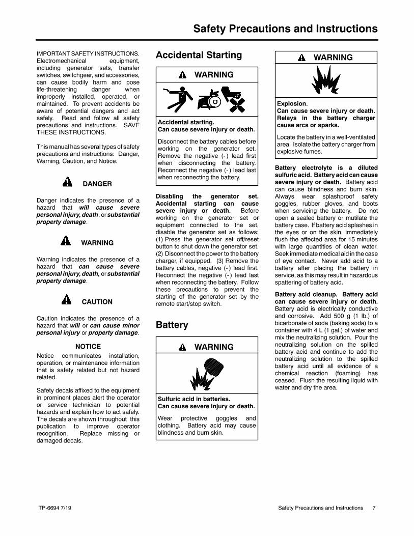
Accidental Starting
Accidental starting.Can cause severe injury or death.
Disconnect the battery cables beforeworking on the generator set.Remove the negative (- ) lead firstwhen disconnecting the battery.Reconnect the negative (- ) lead lastwhen reconnecting the battery.
WARNING
Disabling the generator set.Accidental starting can causesevere injury or death. Beforeworking on the generator set orequipment connected to the set,disable the generator set as follows:(1) Press the generator set off/resetbutton to shut down the generator set.(2) Disconnect the power to the batterycharger, if equipped. (3) Remove thebattery cables, negative (- ) lead first.Reconnect the negative (- ) lead lastwhen reconnecting the battery. Followthese precautions to prevent thestarting of the generator set by theremote start/stop switch.
Battery
Sulfuric acid in batteries.Can cause severe injury or death.
Wear protective goggles andclothing. Battery acid may causeblindness and burn skin.
WARNING
Explosion.Can cause severe injury or death.Relays in the battery chargercause arcs or sparks.
Locate the battery in a well-ventilatedarea. Isolate the battery charger fromexplosive fumes.
WARNING
Battery electrolyte is a dilutedsulfuric acid. Battery acid cancausesevere injury or death. Battery acidcan cause blindness and burn skin.Always wear splashproof safetygoggles, rubber gloves, and bootswhen servicing the battery. Do notopen a sealed battery or mutilate thebattery case. If battery acid splashes inthe eyes or on the skin, immediatelyflush the affected area for 15 minuteswith large quantities of clean water.Seek immediatemedical aid in the caseof eye contact. Never add acid to abattery after placing the battery inservice, as thismay result in hazardousspattering of battery acid.
Battery acid cleanup. Battery acidcan cause severe injury or death.Battery acid is electrically conductiveand corrosive. Add 500 g (1 lb.) ofbicarbonate of soda (baking soda) to acontainer with 4 L (1 gal.) of water andmix the neutralizing solution. Pour theneutralizing solution on the spilledbattery acid and continue to add theneutralizing solution to the spilledbattery acid until all evidence of achemical reaction (foaming) hasceased. Flush the resulting liquid withwater and dry the area.
8 Safety Precautions and Instructions TP-6694 7/19
Battery gases. Explosion can causesevere injury or death. Battery gasescan cause an explosion. Do not smokeor permit flames or sparks to occur neara battery at any time, particularly whenit is charging. Do not dispose of abattery in a fire. To prevent burns andsparks that could cause an explosion,avoid touching the battery terminalswith tools or other metal objects.Remove all jewelry before servicing theequipment. Discharge static electricityfrom your body before touchingbatteries by first touching a groundedmetal surface away from thebattery. Toavoid sparks, do not disturb the batterycharger connections while the batteryis charging. Always turn the batterycharger off before disconnecting thebattery connections. Ventilate thecompartments containing batteries toprevent accumulation of explosivegases.
Battery short circuits. Explosioncan cause severe injury or death.Short circuits can cause bodily injuryand/or equipment damage.Disconnect the battery beforegenerator set installation ormaintenance. Remove all jewelrybefore servicing the equipment. Usetools with insulated handles. Removethe negative (- ) lead first whendisconnecting the battery. Reconnectthe negative (- ) lead last whenreconnecting the battery. Neverconnect the negative (- ) battery cableto the positive (+) connection terminalof the starter solenoid. Do not test thebattery condition by shorting theterminals together.
Battery gases. Explosion can causesevere injury or death. Incorrect useof theequalize charge statemay lead tohazardous situations. Equalization isONLY applicable for flooded lead acid(FLA) type batteries and will damagegel, absorbed glass mat (AGM), ornickel-cadmium (NiCad) type batteries.In the controller menu or SiteTechtsettings, verify that the battery topologyis set correctly for thebattery typeused.Do not smoke or permit flames, sparks,or other sources of ignition to occurnear a battery at any time.
Engine Backfire/FlashFire
Risk of fire.Can cause severe injury or death.
Do not smoke or permit flames orsparks near fuels or the fuel system.
WARNING
Servicing the fuel system. A flashfire cancausesevere injuryordeath.Do not smoke or permit flames orsparks near the carburetor, fuel line,fuel filter, fuel pump, or other potentialsources of spilled fuels or fuel vapors.Catch fuels in an approved containerwhen removing the fuel line orcarburetor.
Servicing the air cleaner. A suddenbackfire can cause severe injury ordeath. Do not operate the generatorset with the air cleaner removed.
Combustible materials. A fire cancause severe injury or death.Generator set engine fuels and fuelvapors are flammable and explosive.Handle these materials carefully tominimize the risk of fire or explosion.Equip the compartment or nearby areawith a fully charged fire extinguisher.Select a fire extinguisher rated ABC orBC for electrical fires or asrecommended by the local fire code oran authorized agency. Train allpersonnel on fire extinguisheroperation and fire preventionprocedures.
Exhaust System
Carbon monoxide.Can cause severe nausea,fainting, or death.
The exhaust system must beleakproof and routinely inspected.
WARNING
Generator set operation. Carbonmonoxide can cause severe nausea,fainting, or death. Carbon monoxideis an odorless, colorless, tasteless,nonirritating gas that can cause death ifinhaled for even a short time. Avoidbreathing exhaust fumeswhenworkingon or near the generator set. Neveroperate the generator set inside abuilding unless the exhaust gas ispiped safely outside. Never operatethe generator set where exhaust gascould accumulate and seepback insidea potentially occupied building.
Carbon monoxide symptoms.Carbon monoxide can cause severenausea, fainting, or death. Carbonmonoxide is a poisonous gas present inexhaust gases. Carbonmonoxide is anodorless, colorless, tasteless,nonirritating gas that can cause death ifinhaled for even a short time. Carbonmonoxide poisoning symptoms includebut are not limited to the following:D Light-headedness, dizzinessD Physical fatigue, weakness injoints and muscles
D Sleepiness, mental fatigue,inability to concentrateor speak clearly, blurred vision
D Stomachache, vomiting, nauseaIf experiencing any of these symptomsand carbon monoxide poisoning ispossible, seek fresh air immediatelyand remain active. Do not sit, lie down,or fall asleep. Alert others to thepossibility of carbon monoxidepoisoning. Seek medical attention ifthe condition of affected persons doesnot improvewithinminutes of breathingfresh air.
9Safety Precautions and InstructionsTP-6694 7/19
Fuel System
Explosive fuel vapors.Can cause severe injury or death.
Use extreme care when handling,storing, and using fuels.
WARNING
The fuel system. Explosive fuelvapors can cause severe injury ordeath. Vaporized fuels are highlyexplosive. Use extreme care whenhandling and storing fuels. Store fuelsin a well-ventilated area away fromspark-producing equipment and out ofthe reach of children. Never add fuel tothe tank while the engine is runningbecause spilled fuel may ignite oncontact with hot parts or from sparks.Do not smoke or permit flames orsparks to occur near sources of spilledfuel or fuel vapors. Keep the fuel linesand connections tight and in goodcondition. Do not replace flexible fuellines with rigid lines. Use flexiblesections to avoid fuel line breakagecausedby vibration. Donot operate thegenerator set in the presence of fuelleaks, fuel accumulation, or sparks.Repair fuel systems before resuminggenerator set operation.
Explosive fuel vapors can causesevere injury or death. Takeadditional precautions when using thefollowing fuels:
Propane (LPG)—Adequate ventilationis mandatory. Because propane isheavier than air, install propane gasdetectors low in a room. Inspect thedetectors per the manufacturer’sinstructions.
Natural Gas—Adequate ventilation ismandatory. Because natural gas rises,install natural gas detectors high in aroom. Inspect the detectors per themanufacturer’s instructions.
Fuel tanks. Explosive fuel vaporscan cause severe injury or death.Gasoline and other volatile fuels storedin day tanks or subbase fuel tanks cancause an explosion. Store only dieselfuel in tanks.
Draining the fuel system. Explosivefuel vapors can cause severe injuryor death. Spilled fuel can cause anexplosion. Usea container to catch fuelwhendraining the fuel system. Wipeupspilled fuel after draining the system.
Gas fuel leaks. Explosive fuelvapors can cause severe injury ordeath. Fuel leakage can cause anexplosion. Check the LPG vapor ornatural gas fuel system for leakage byusing a soap and water solution withthe fuel system test pressurized to6- 8 ounces per square inch(10- 14 inches water column). Do notuse a soap solution containing eitherammonia or chlorine because bothprevent bubble formation. A successfultest depends on the ability of thesolution to bubble.
LPG liquid withdrawal fuel leaks.Explosive fuel vapors can causesevere injury or death. Fuel leakagecan cause an explosion. Check theLPG liquid withdrawal fuel system forleakage by using a soap and watersolution with the fuel system testpressurized to at least 90 psi(621 kPa). Do not use a soap solutioncontaining either ammonia or chlorinebecause both prevent bubbleformation. A successful test dependson the ability of the solution to bubble.
Hazardous Noise
Hazardous noise.Can cause hearing loss.
Never operate the generator setwithout a muffler or with a faultyexhaust system.
CAUTION
Engine noise. Hazardous noise cancause hearing loss. Generator setsnot equipped with sound enclosurescan produce noise levels greater than105 dBA. Prolonged exposure to noiselevels greater than 85 dBA can causepermanent hearing loss. Wear hearingprotection when near an operatinggenerator set.
Hazardous Voltage/Moving Parts
Hazardous voltage.Will cause severe injury or death.
Disconnect all power sources beforeopening the enclosure.
DANGER
Hazardous voltage. Moving parts.Will cause severe injury or death.
Operate the generator set only whenall guards and electrical enclosuresare in place.
DANGER
Hazardous voltage.Backfeed to the utility system cancause property damage, severeinjury, or death.
If the generator set is used forstandby power, install an automatictransfer switch to prevent inadvertentinterconnection of standby andnormal sources of supply.
WARNING
Grounding electrical equipment.Hazardousvoltagewill causesevereinjury or death. Electrocution ispossible whenever electricity ispresent. Ensure you comply with allapplicable codes and standards.Electrically ground the generator set,transfer switch, and related equipmentand electrical circuits. Turn off themaincircuit breakers of all power sourcesbefore servicing the equipment. Nevercontact electrical leads or applianceswhen standing in water or on wetground because these conditionsincrease the risk of electrocution.
10 Safety Precautions and Instructions TP-6694 7/19
High voltage test. Hazardousvoltage will cause severe injury ordeath. Follow the instructions of thetest equipment manufacturer whenperforming high-voltage tests on therotor or stator. An improper testprocedure can damage equipment orlead to generator set failure.
Installing the battery charger.Hazardousvoltagewill causesevereinjury or death. An ungroundedbattery charger may cause electricalshock. Connect the battery chargerenclosure to the ground of a permanentwiring system. As an alternative, installan equipment grounding conductorwith circuit conductors and connect it tothe equipment grounding terminal orthe lead on the battery charger. Installthe battery charger as prescribed in theequipment manual. Install the batterycharger in compliance with local codesand ordinances.
Connecting the battery and thebattery charger. Hazardous voltagewill cause severe injury or death.Reconnect the battery correctly,positive to positive and negative tonegative, to avoid electrical shock anddamage to the battery charger andbattery(ies). Have a qualifiedelectrician install the battery(ies).
Short circuits. Hazardousvoltage/current will cause severeinjury or death. Short circuits cancause bodily injury and/or equipmentdamage. Do not contact electricalconnections with tools or jewelry whilemaking adjustments or repairs.Remove all jewelry before servicing theequipment.
Engine block heater. Hazardousvoltage will cause severe injury ordeath. The engine block heater cancause electrical shock. Remove theengine block heater plug from theelectrical outlet before working on theblock heater electrical connections.
Electrical backfeed to the utility.Hazardous backfeed voltage cancause severe injury or death. Installa transfer switch in standby powerinstallations to prevent the connectionof standby and other sources of power.Electrical backfeed into a utilityelectrical system can cause severeinjury or death to utility personnelworking on power lines.
Testing live electrical circuits.Hazardous voltage or current willcause severe injury or death. Havetrained and qualified personnel takediagnostic measurements of livecircuits. Use adequately rated testequipment with electrically insulatedprobes and follow the instructions of thetest equipment manufacturer whenperforming voltage tests. Observe thefollowing precautions when performingvoltage tests: (1) Remove all jewelry.(2) Standonadry, approvedelectricallyinsulated mat. (3) Do not touch theenclosure or components inside theenclosure. (4) Be prepared for thesystem to operate automatically.(600 volts and under)
Servicing the generator set when itis operating. Exposedmoving partswill cause severe injury or death.Keep hands, feet, hair, clothing, andtest leads away from the belts andpulleys when the generator set isrunning. Replace guards, screens, andcovers before operating the generatorset.
Heavy Equipment
Unbalanced weight.Improper lifting can cause severeinjury or death and equipmentdamage.
Do not use lifting eyes.Lift the generator set using lifting barsinserted through the lifting holes onthe skid.
WARNING
Hot Parts
Hot coolant and steam.Can cause severe injury or death.
Before removing the pressure cap,stop the generator set and allow it tocool. Then loosen the pressure capto relieve pressure.
WARNING
Hot engine and exhaust system.Can cause severe injury or death.
Do not work on the generator set untilit cools.
WARNING
Servicing the alternator. Hot partscan cause severe injury or death.Avoid touching the alternator field orexciter armature. When shorted, thealternator field and exciter armaturebecome hot enough to cause severeburns.
Servicing the exhaust system. Hotparts can cause severe injury ordeath. Do not touch hot engine parts.The engine and exhaust systemcomponents become extremely hotduring operation.
11Safety Precautions and InstructionsTP-6694 7/19
Notice
NOTICE
This generator set has beenrewired from its nameplate voltageto
246242
NOTICEVoltage reconnection. Affix a noticeto the generator set after reconnectingthe set to a voltage different from thevoltage on the nameplate. Ordervoltage reconnection decal 246242from an authorized servicedistributor/dealer.
NOTICECanadian installations only. Forstandby service connect the output ofthe generator set to a suitably ratedtransfer switch in accordance withCanadian Electrical Code, Part 1.

12 Safety Precautions and Instructions TP-6694 7/19
Notes
13IntroductionTP-6694 7/19
Introduction
This manual provides operation instructions for 10 kWand larger generator sets equipped with the followingcontrollers:
D APM402 generator set controller
D Decision-Makerr 3000 generator set controller
Note: In 2018, Kohler adopted a global controllernaming convention. To support this, the name ofthe Decision-Makerr 3000 controller hastransitioned to APM402. The APM402 has thesame form, fit and function as theDecision-Makerr 3000 and supports the sameaccessories.
Wiring diagrammanuals are available separately. Referto the engine operationmanual for generator set enginescheduled maintenance information.
Information in this publication represents data availableat the time of print. Kohler Co. reserves the right tochange this publication and the products representedwithout notice and without any obligation or liabilitywhatsoever.
Read this manual and carefully follow all proceduresand safety precautions to ensure proper equipmentoperation and to avoid bodily injury. Read and follow theSafety Precautions and Instructions section at thebeginning of this manual. Keep this manual with theequipment for future reference.
The equipment service requirements are very importantto safe and efficient operation. Inspect the parts oftenand perform required service at the prescribed intervals.Maintenance work must be performed by appropriatelyskilled and suitably trained maintenance personnelfamiliar with generator set operation and service.
Abbreviations
This publication makes use of numerous abbreviations.Typically, the word(s) are spelled out along with theabbreviation in parentheses when shown for the firsttime in a section. Appendix A, Abbreviations, alsoincludes many abbreviation definitions.
SiteTecht Software
Several instances in this manual refer to SiteTechtsoftware, which can be used for programming theAPM402 or Decision-Makerr 3000 controller.SiteTecht software is required for updating thecontroller application code (firmware), loadingpersonality profiles, and saving or loading controllerconfiguration files. Contact your local distributor/dealerfor assistance.
Note: The APM402 controller uses different firmwarethan the Decision-Makerr 3000 controller. Donot attempt to load Decision-Makerr 3000firmware on an APM402 controller, or vice-versa.
To determine the generator set controller softwareversion, go to the Overview menu.
List of Related Materials
Separate literature contains communication andsoftware information not provided in this manual.Figure 1 lists the available literature part numbers.
Literature Description Literature Part No.
APM402 Controller Spec Sheet G6-161
Decision-Makerr 3000 Controller SpecSheet G6-100
Generator Set/ControllerWiring Diagram Manual
Multiple Part NumbersContact your
Distributor/Dealer
Modbusr Communications ProtocolOperation Manual TP-6113
SiteTecht Software Operation Manual TP-6701
Remote Serial Annunciator (RSA III) TT-1625
Remote Serial Annunciator (RSA II) TT-1485
Converters, Connections, and ControllerSetup for Network Communication TT-1405
Figure 1 Related Literature
Several engine manufacturers provide engines withelectronic controls. These electronic controls indicateengine fault codes in addition to the generator setcontroller. The engine operation and service literatureprovide information for identifying engine fault codes.For the latest literature part numbers, see the respectiveParts Catalog.
Modbusr is a registered trademark of Schneider Electric.
14 Service Assistance TP-6694 7/19
Service Assistance
For professional advice on generator set powerrequirements and conscientious service, please contactyour nearest Kohler distributor or dealer.
D Visit the Kohler Co. website at KOHLERPower.com.
D Look at the labels and decals on your Kohler productor review the appropriate literature or documentsincluded with the product.
D Call toll free in the US and Canada 1-800-544-2444.
D Outside theUS andCanada, call the nearest regionaloffice.
Headquarters Europe, Middle East, Africa(EMEA)Kohler EMEA HeadquartersNetherlands B.V.Kristallaan 14761 ZC ZevenbergenThe NetherlandsPhone: (31) 168 331630Fax: (31) 168 331631
Asia PacificKohler Asia Pacific HeadquartersSingapore, Republic of SingaporePhone: (65) 6264-6422Fax: (65) 6264-6455
ChinaNorth China Regional Office, BeijingPhone: (86) 10 6518 7950
(86) 10 6518 7951(86) 10 6518 7952
Fax: (86) 10 6518 7955
East China Regional Office, ShanghaiPhone: (86) 21 6288 0500Fax: (86) 21 6288 0550
India, Bangladesh, Sri LankaIndia Regional OfficeBangalore, IndiaPhone: (91) 80 3366208
(91) 80 3366231Fax: (91) 80 3315972
Japan, KoreaNorth Asia Regional OfficeTokyo, JapanPhone: (813) 3440-4515Fax: (813) 3440-2727
TP-6694 7/19 15Section 1 Specifications and Features
Section 1 Specifications and Features
1.1 Introduction
The spec sheets for each generator set provide model-specific generator and engine information. Thecontroller spec sheet provides specifications for thiscontroller. Refer to the respective spec sheet for datanot supplied in this manual. Refer to the generator setservice manual, installation manual, engine operationmanual, and engine service manual for additionalspecifications.
1.2 Controller Features
The controller features include the annunciator lamp,digital display and pushbutton/rotary selector dial,switches and controls, and fuses and terminal strip. Thefollowing paragraphs detail the features by generaltopics.
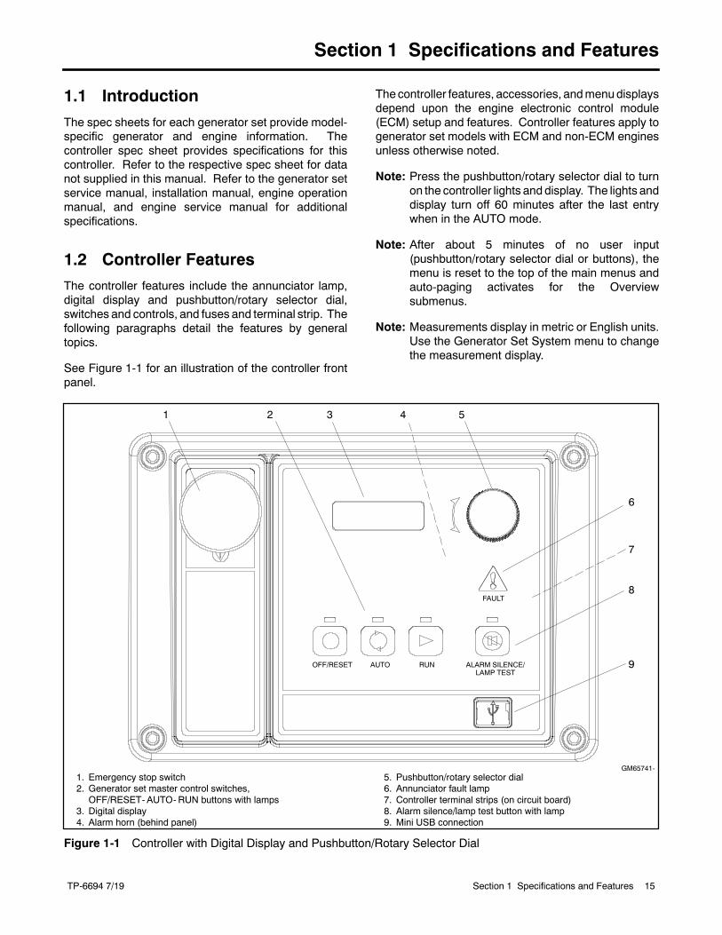
See Figure 1-1 for an illustration of the controller frontpanel.
The controller features, accessories, andmenudisplaysdepend upon the engine electronic control module(ECM) setup and features. Controller features apply togenerator set models with ECM and non-ECM enginesunless otherwise noted.
Note: Press the pushbutton/rotary selector dial to turnon the controller lights and display. The lights anddisplay turn off 60 minutes after the last entrywhen in the AUTO mode.
Note: After about 5 minutes of no user input(pushbutton/rotary selector dial or buttons), themenu is reset to the top of the main menus andauto-paging activates for the Overviewsubmenus.
Note: Measurements display in metric or English units.Use the Generator Set System menu to changethe measurement display.
1. Emergency stop switch2. Generator set master control switches,
OFF/RESET- AUTO-RUN buttons with lamps3. Digital display4. Alarm horn (behind panel)
5. Pushbutton/rotary selector dial6. Annunciator fault lamp7. Controller terminal strips (on circuit board)8. Alarm silence/lamp test button with lamp9. Mini USB connection
GM65741-
1 2 4 5
7
8
3
6
FAULT
OFF/RESET AUTO RUN ALARM SILENCE/LAMP TEST
9
Figure 1-1 Controller with Digital Display and Pushbutton/Rotary Selector Dial
TP-6694 7/1916 Section 1 Specifications and Features
1.2.1 Switches and Controls
Note: US/Metric Display is selectable in Section1.2.3—Digital Display—Generator Set SystemMenu.
AlarmHorn. Thealarmhorn alerts the operator or otherattendants that a shutdown or warning condition exists.
Alarm (Horn) Silence. The alarm silence/lamp testswitch silences the alarm horn at the operator’sdiscretion. Press the master control switch AUTObutton before pressing the alarm silence/lamp testbutton. The alarm horn cannot be silenced unless themaster control switch AUTO button is pressed.
Note: Additional alarm silencing options are shown inSection 1.2.3—Digital Display—Generator SetSystem Menu.
Restore alarm horn switches at all locations includingthose on remote annunciator kits after correcting thefault shutdown to avoid reactivating the alarmhorn. SeeSection 2—Operation, 2.4.8 Controller Resetting forresetting the controller.
Emergency Stop. The operator-activated pushbuttonimmediately shuts down the generator set in emergencysituations. Reset the emergency stop switch aftershutdown by pulling the emergency stop switchoutward. Use theemergency stop switch for emergencyshutdowns only. Use the master control switchOFF/RESET button for normal shutdowns.
Generator Set Master Control Switches(OFF/RESET-AUTO-RUN). These switches reset thecontroller fault lamps and start/stops the generator set.Additional information in shown in Section 2—Operation.
Lamp Test. Press and hold the Alarm Silence/LampTest button for two seconds to test the controllerindicator lamps, alarm horn, and digital display.
Manual Speed Adjust (Engine RPM). The controlallows varying the engine speed for applications usingclosed transition ATS. The user can set the nominalrunning frequency slightly above or below the utilityfrequency to ensure that synchronization occurs.Additional information is shown in 2.7.7 GenSetSystem. Available as a factory-installed option orrequires a new factory personality profile.
Pushbutton/Rotary Selector Dial. This controlprovides access to the menus for monitoring. Press theselector dial to activate the digital display and to selectchoices shown on the display. Rotate the dial tonavigate through the menus.
The pushbutton/rotary selector dial has several featuresand functions:
D Momentarily press the dial to activate the digitaldisplay if dark.
D Rotate the dial to navigate through the mainmenus—turn clockwise to go forward (down) andcounterclockwise to go back (up). The menus do notwrap to the beginning.
D Press the dial at a given main menu to access thesubmenus within the selected main menu.
D When in the submenu, rotate the dial to navigatethrough the submenu—clockwise to go forward(down) and counterclockwise to go back (up). Themenus do not wrap to the beginning.
D Momentarily press the dial when in the submenu tomake a user selection choice (if available) or to goback to the respective main menu.
D Press thedial for at least 3 seconds to return to the topof themainmenus (Overview) regardless if you are inthe main menus or submenus.
D After about 5 minutes of no user input (pushbutton/rotary selector dial or buttons), themenu resets to thetop of the main menus and auto-paging activates forthe Overview submenus.
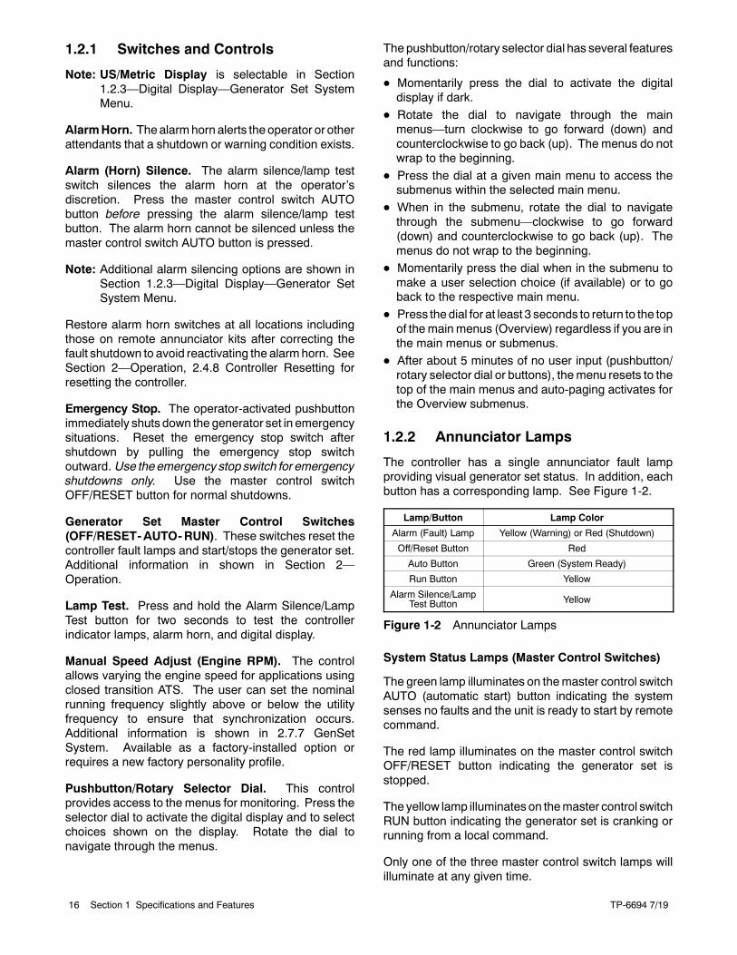
1.2.2 Annunciator Lamps
The controller has a single annunciator fault lampproviding visual generator set status. In addition, eachbutton has a corresponding lamp. See Figure 1-2.
Lamp/Button Lamp Color
Alarm (Fault) Lamp Yellow (Warning) or Red (Shutdown)
Off/Reset Button Red
Auto Button Green (System Ready)
Run Button Yellow
Alarm Silence/LampTest Button Yellow
Figure 1-2 Annunciator Lamps
System Status Lamps (Master Control Switches)
The green lamp illuminates on themaster control switchAUTO (automatic start) button indicating the systemsenses no faults and the unit is ready to start by remotecommand.
The red lamp illuminates on the master control switchOFF/RESET button indicating the generator set isstopped.
The yellow lamp illuminates on themaster control switchRUN button indicating the generator set is cranking orrunning from a local command.
Only one of the three master control switch lamps willilluminate at any given time.
TP-6694 7/19 17Section 1 Specifications and Features
Alarm Silence Lamp. Yellow lamp illuminatesindicating the alarm horn was silenced.
(System) Fault Lamp. Yellow lamp illuminatesindicating a warning condition or red lamp illuminatesindicating a shutdown condition. See System WarningFault Lamp andSystemShutdownFault Lamp followingfor system fault conditions.
System Warning Fault Lamp. Yellow lamp identifiesan existing fault condition that does not shut down thegenerator set. A continuing system warning faultcondition may cause a system shutdown. Correct allsystem warnings as soon as practical.
See Section 2.4.5, System Fault Warning Lamp withDigital Displays, for definitions of the items listed. Thefollowing conditions cause a system warning:
D AC sensing lossD Auxiliary input (analog or digital)
D Battery charger communication loss
D Battery charger fault *
Note: Optional input sensors not required with chargerGM87448.
D Battery charger identity conflict
D Battery charger parameter mismatch
D Battery faultD Common warning
D Critical high fuel level (diesel-poweredmodels only) *
D Default parameters loaded
D ECM diagnostics (multiple engine inputs)
D Fuel tank leak (diesel-powered models only) *D Ground fault *
D High battery voltage
D High coolant temperature
D High fuel level (diesel-powered models only) *
D Input/output communication loss
D Low battery voltageD Low coolant temperature
D Low cranking voltage
D Low engine oil level *
D Low fuel (level for diesel-powered models) *
D Low fuel (pressure for gas-powered models) *D Low oil pressure
D Not-in-auto (master control switch)D Speed sensor fault
* Requires optional input sensors with all battery chargers exceptbattery charger GM87448.
System Shutdown Fault Lamp. Red lamp indicatesthat the generator set has shut down because of a faultcondition. The unit will not start without resetting thecontroller, see Section 2.4.8, Controller Resettingprocedure.
See Section 2.4.6, System Fault Shutdown Lamp withDigital Displays, for definitions of the items listed. Thefollowing conditions cause a system shutdown:
D AC sensing loss
D Alternator protection
D Auxiliary input (analog or digital)
D Common fault
D ECM address conflict
D ECM communications lossD ECM diagnostics (multiple engine inputs)
D ECM model mismatch
D Emergency stop
D Enclosure temperature: high shutdown (available onselect Telecom units only)
D Engine over speedD Engine under speed
D File system error (controller firmware fault)D Fuel tank leak (diesel-powered models only) *
D High coolant temperature
D Internal failureD kW overload
D Locked rotor (failed to crank)
D Loss of fuel
D Low coolant level *
D Low engine oil level *
D Low fuel level (diesel-powered models only) *D Low oil pressure
D Megajector communications loss(GM/PSI and Doosan gas-powered models only)
D Metering communication loss
D No coolant temperature signal
D No oil pressure signalD Overcrank
D Overfrequency
D Overvoltage (each phase)
D Run relay overload
D UnderfrequencyD Undervoltage (each phase)
D (Voltage) regulator communication loss
* Requires optional input sensors.
TP-6694 7/1918 Section 1 Specifications and Features
1.2.3 Digital Display
Press the pushbutton/rotary selector dial to turn on thecontroller lamps and display. The lamps and displayturn off 60 minutes after the last entry.
Note: The APM402 controller takes about 5- 10seconds to power on.
The generator set must be running for some displays toindicate values. If the generator set is not running somevalues will display zero or N/A (not available).
Some displays are engine dependent, refer to theAppendix, Controller Displays from the Engine ECM.
The 12-character, 2-line backlit heated display providesgenerator set and engine data, system status, and faultinformation. See Figure 1-1. The digital display showsabbreviations in some instances, refer to 1.3.1 StatusEvent and Fault Specifications for the abbreviations andtheir full descriptions.
Note: US/Metric Unit Display is selectable inGenerator Set System.
Note: Display Contrast is selectable in Generator SetSystem. The contrast display adjustment allowsuser selected resolution values to improve digitaldisplay clarity.
Note: After about 5 minutes of no user input(pushbutton/rotary selector dial or buttons), themenu resets to the top of the main menus andauto-paging activates for the Overviewsubmenus.
The main menus are listed below. Within each mainmenu are multiple submenus with descriptionsfollowing.
D OverviewD Engine Metering
D Generator Metering
D GenSet Information
D GenSet Run Time
D GenSet System
D GenSet Calibration (Decision-Makerr 3000controllers before Version 3.0.25)
D Voltage Regulation
D Digital Inputs
D Digital Outputs
D Analog Inputs
D Event LogD Volt Select
Overview Menu
When a new shutdown or warning fault occurs, theauto-paging display feature activates.
Active Shutdowns display if any are present. Thisalerts the user to single or multiple shutdown faultconditions. See 1.2.2—Annunciator Lamps—SystemShutdown Fault Lamp for a list of possible shutdownfaults.
ActiveWarnings display if any are present. This alertsthe user to single or multiple warning fault conditions.See 1.2.2—Annunciator Lamps—System WarningFault Lamp for a list of possible warning faults.
Generator Set State displays the generator set status:
D OffD Standby
D Running
D Cooldown
D Stopping
Average Volts Line-to-Line value displays. Forthree-phase configurations the average line-to-linevoltage of L1, L2, and L3 is displayed. Single-phaseconfigurations show the L1-L2 voltage.
Frequency (Hz) value displays for the output ACvoltage.
Current value displays as the average for three-phaseconfigurations or the current value for L1-L2 withsingle-phase configurations.
Average kW displays. For three-phase configurationsthe average line-to-line kilowatts of L1, L2, and L3 isdisplayed. Single-phase configurations show the L1-L2kilowatts.
Coolant Temperature diplays for the engine coolanttemperature.
Oil Pressure displays the engine oil pressure.
Fuel Level % displays the fuel tank level for diesel-powered models when so equipped.
Fuel Pressure displays fuel pressure for someengines.Refer to the Appendix, Controller Displays from theEngine ECM.
Battery displays the DC voltage of the engine startingbattery(ies).
CHG1 and CHG2 display battery charger voltage andcurrent (amps) if one or two CAN-enabled 10 Ampbattery chargers (GM87448 only) have beenconnected. Shows N/A if charger GM87448 was
TP-6694 7/19 19Section 1 Specifications and Features
connected and then removed. (DEC3000 version 4.11or higher, and APM402)
Engine Run Time displays the total run time hours.
Software Version displays in the Overviewmenu. Usethe version number to determine if an upgrade isneeded and/or when troubleshooting the controller.
Engine Metering Menu
Note: The Engine Metering Menu may vary dependingupon if the selector dial is rotated clockwise orcounterclockwise.
Engine Speed (Tachometer) displays the enginespeed in RPM.
Oil Pressure displays the engine oil pressure. Thisvalue also shows in the Overview Menu.
Coolant Temperature displays the engine coolanttemperature. This value also shows in the OverviewMenu.
Fuel Level % displays the fuel tank level for diesel-powered models if so equipped. This value also showsin the Overview Menu.
Battery displays the DC voltage of the engine startingbattery(ies). This value also shows in the OverviewMenu.
Fuel Pressure displays fuel pressure for someengines.Refer to the Appendix, Controller Displays from theEngine ECM. This value also shows in the OverviewMenu.
Generator Metering Menu
Total Power kVA and kW displays alternator output asactual output values.
Rated Power displays alternator output as apercentage of the entered data value.
Volts displays the alternator output AC voltages. Thedisplay shows all line-to-line and line-to-neutral voltagecombinations for three-phase or single-phaseconfigurations.
Current displays the alternator output AC amps. Thedisplay shows each line (L1-L2-L3) of three-phasemodels or L1-L2 current for single-phase models.
Frequency (Hz) value displays for the output ACvoltage. This value also shows in the Overview Menu.
Reset Calibration providing the means to reset theconfiguration values is available in this menu.
The calibration values are reviewable at all times andprovide the calibration of the voltage and currentsensing logic. Changing the system voltage orreplacing the circuit board requires a calibrationadjustment.
To enable calibration, start the generator set and selectthe Volts L1-L2 display. Then push and hold thepushbutton/rotary selector dial until the CalibrationEnabled popup appears. Calibration of each display isnow available. The display will show the followingvalues for three-phase generator sets. Single-phasegenerator sets will only display items marked (*).
D Volts L1-L2 *
D Volts L2-L3
D Volts L3-L1D Volts L1-N *
D Volts L2-N *
D Volts L3-ND Current L1 *
D Current L2 *
D Current L3
The user can change individual values or can selectReset Calib?-Yes to reset all values. The Reset Calib?display will only show if calibration is enabled. Refer tothe requirements shown with Generator Set Calibrationin 2.4.7 Status and Notice Digital Displays.
To disable calibration, Rotate the pushbutton/rotaryselector dial until the <-Return popup appears.Momentarily press the pushbutton/rotary selector dial.Stop the generator set if not already done.
Generator Set Information Menu
GenSet M/N displays the generator set model number.
GenSet S/N displays the generator set serial number.
Controller S/N displays the controller serial number.
Generator Set Run Time Menu
Engine Run Time displays the total run time hours.This value also shows in the Overview Menu.
Engine Loaded displays the total loaded hours.
Engine Starts displays the total number of generatorset startup events.
Total Energy displays the total kW hours.
TP-6694 7/1920 Section 1 Specifications and Features
Generator Set System Menu
The values in this menus are user-entered for thegenerator set configuration and are NOT measuredvalues of the generator set.
Changes to theGenerator Set Systemmenu require theuse of SiteTecht software except for Measure Systemand Contrast selections.
System Frequency displays the programmer-enteredL1-L2-L3 output voltage frequency for three-phase orthe L1-L2 output voltage frequency for single-phase.
System Phase displays the programmer-enteredconfiguration as Single Phase, Single Phase Dog Leg,Three Phase Wye, or Three Phase Delta.
System Voltage displays the programmer-enteredL1-L2-L3 output voltage for three-phase or the L1-L2output voltage for single-phase.
Power Rating displays the programmer entered kWvalue for the generator set.
Amp Rating displays the programmer entered currentvalue for the generator set.
Power Type displays the programmer enteredgenerator set application configuration as Standby orPrime.
Battery Voltage displays the engine electrical system12 or 24 volts.
Measurement System displays the user selected unitof measure as Metric or English.
Contrast displays user selected resolution values toimprove digital display clarity.
Alarm (Horn) Silence displays the programmerselected alarm silence method as Always or Auto Onlyusing SiteTecht software. The Always selection allowsthe alarm to be silenced in any of theOFF/RESET- AUTO-RUN modes. The Auto Onlyselection allows silencing of the alarm only while in theAuto mode.
Note: Press the Alarm Silence/Lamp Test button tosilence the alarm horn.
Manual Speed Adjust (Engine RPM) is available as auser selectable adjustment. The user can set thenominal running frequency slightly above or below theutility frequency to ensure that synchronization occurs.Refer to 2.7.7 GenSet System for more information.Available as a factory-installed option or requires a newfactory personality profile.
Generator Set (Reset) Calibration Menu
This menu is only available in Decision-Makerr 3000controller firmware versions before 3.0.25. OnDecision-Makerr 3000 controllers with later firmwareversions, or on APM402 controllers, go to GeneratorMetering Menu—Reset Calibration.
The calibration values are reviewable at all times andprovide the calibration of the voltage and currentsensing logic. Changing the system voltage orreplacing the circuit board requires a calibrationadjustment. In order to review the values when thegenerator set is NOT running, enter Yes when the EnterCalib? is displayed. The user can review the values butattempting to change the values will cause a Cannotcalibrate error message.
If the unit is NOT running and No is entered when theEnter Calib? is shown, the display returns to theGenerator Set Calibration main menu and entry to theGenerator Set Calibration menu is denied.
If the unit is running and Yes is entered when the EnterCalib? is shown, the display will show the followingvalues for three-phase generator sets. Single-phasegenerator sets will only display items marked (*).
D Volts L1-L2 *
D Volts L2-L3
D Volts L3-L1
D Volts L1-N *
D Volts L2-N *D Volts L3-N
D Current L1 *D Current L2 *
D Current L3
The user can change individual values or can enter Yeswhen Reset all Calib? is displayed. At the end of theGenerator Set Calibration menu, Exit calibration isshown. Press the pushbutton/rotary selector dial to exitthis menu. Refer to the requirements shown withGenerator Set Calibration in 2.4.7 Status and NoticeDigital Displays.
TP-6694 7/19 21Section 1 Specifications and Features
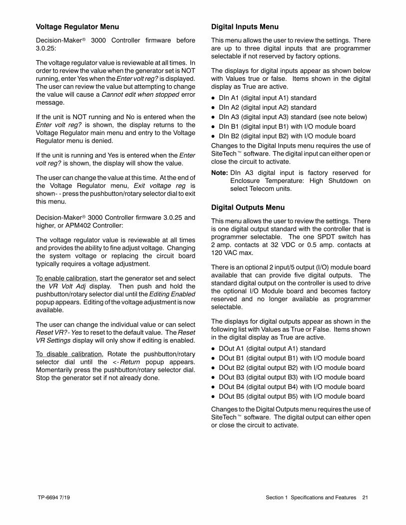
Voltage Regulator Menu
Decision-Makerr 3000 Controller firmware before3.0.25:
The voltage regulator value is reviewable at all times. Inorder to review the value when the generator set is NOTrunning, enter Yeswhen theEnter volt reg? is displayed.The user can review the value but attempting to changethe value will cause a Cannot edit when stopped errormessage.
If the unit is NOT running and No is entered when theEnter volt reg? is shown, the display returns to theVoltage Regulator main menu and entry to the VoltageRegulator menu is denied.
If the unit is running and Yes is entered when the Entervolt reg? is shown, the display will show the value.
The user can change the value at this time. At the end ofthe Voltage Regulator menu, Exit voltage reg isshown- - press thepushbutton/rotary selector dial to exitthis menu.
Decision-Makerr 3000 Controller firmware 3.0.25 andhigher, or APM402 Controller:
The voltage regulator value is reviewable at all timesand provides the ability to fine adjust voltage. Changingthe system voltage or replacing the circuit boardtypically requires a voltage adjustment.
To enable calibration, start the generator set and selectthe VR Volt Adj display. Then push and hold thepushbutton/rotary selector dial until the Editing Enabledpopupappears. Editing of the voltageadjustment is nowavailable.
The user can change the individual value or can selectReset VR?-Yes to reset to the default value. TheResetVR Settings display will only show if editing is enabled.
To disable calibration, Rotate the pushbutton/rotaryselector dial until the <-Return popup appears.Momentarily press the pushbutton/rotary selector dial.Stop the generator set if not already done.
Digital Inputs Menu
This menu allows the user to review the settings. Thereare up to three digital inputs that are programmerselectable if not reserved by factory options.
The displays for digital inputs appear as shown belowwith Values true or false. Items shown in the digitaldisplay as True are active.
D DIn A1 (digital input A1) standard
D DIn A2 (digital input A2) standardD DIn A3 (digital input A3) standard (see note below)
D DIn B1 (digital input B1) with I/O module board
D DIn B2 (digital input B2) with I/O module board
Changes to the Digital Inputs menu requires the use ofSiteTecht software. The digital input can either openorclose the circuit to activate.
Note: DIn A3 digital input is factory reserved forEnclosure Temperature: High Shutdown onselect Telecom units.
Digital Outputs Menu
This menu allows the user to review the settings. Thereis one digital output standard with the controller that isprogrammer selectable. The one SPDT switch has2 amp. contacts at 32 VDC or 0.5 amp. contacts at120 VAC max.
There is an optional 2 input/5 output (I/O) module boardavailable that can provide five digital outputs. Thestandard digital output on the controller is used to drivethe optional I/O Module board and becomes factoryreserved and no longer available as programmerselectable.
The displays for digital outputs appear as shown in thefollowing list with Values as True or False. Items shownin the digital display as True are active.
D DOut A1 (digital output A1) standard
D DOut B1 (digital output B1) with I/O module boardD DOut B2 (digital output B2) with I/O module boardD DOut B3 (digital output B3) with I/O module board
D DOut B4 (digital output B4) with I/O module board
D DOut B5 (digital output B5) with I/O module board
Changes to theDigital Outputsmenu requires the use ofSiteTecht software. The digital output can either openor close the circuit to activate.
TP-6694 7/1922 Section 1 Specifications and Features
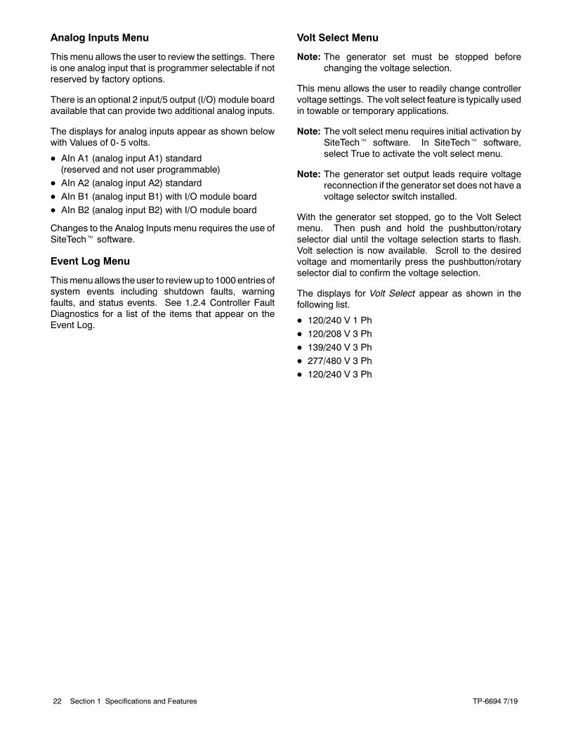
Analog Inputs Menu
This menu allows the user to review the settings. Thereis one analog input that is programmer selectable if notreserved by factory options.
There is an optional 2 input/5 output (I/O) module boardavailable that can provide two additional analog inputs.
The displays for analog inputs appear as shown belowwith Values of 0- 5 volts.
D AIn A1 (analog input A1) standard(reserved and not user programmable)
D AIn A2 (analog input A2) standard
D AIn B1 (analog input B1) with I/O module board
D AIn B2 (analog input B2) with I/O module board
Changes to the Analog Inputs menu requires the use ofSiteTecht software.
Event Log Menu
Thismenuallows the user to reviewup to 1000entries ofsystem events including shutdown faults, warningfaults, and status events. See 1.2.4 Controller FaultDiagnostics for a list of the items that appear on theEvent Log.
Volt Select Menu
Note: The generator set must be stopped beforechanging the voltage selection.
This menu allows the user to readily change controllervoltage settings. The volt select feature is typically usedin towable or temporary applications.
Note: The volt select menu requires initial activation bySiteTecht software. In SiteTecht software,select True to activate the volt select menu.
Note: The generator set output leads require voltagereconnection if the generator set does not have avoltage selector switch installed.
With the generator set stopped, go to the Volt Selectmenu. Then push and hold the pushbutton/rotaryselector dial until the voltage selection starts to flash.Volt selection is now available. Scroll to the desiredvoltage and momentarily press the pushbutton/rotaryselector dial to confirm the voltage selection.
The displays for Volt Select appear as shown in thefollowing list.
D 120/240 V 1 Ph
D 120/208 V 3 Ph
D 139/240 V 3 Ph
D 277/480 V 3 PhD 120/240 V 3 Ph
TP-6694 7/19 23Section 1 Specifications and Features
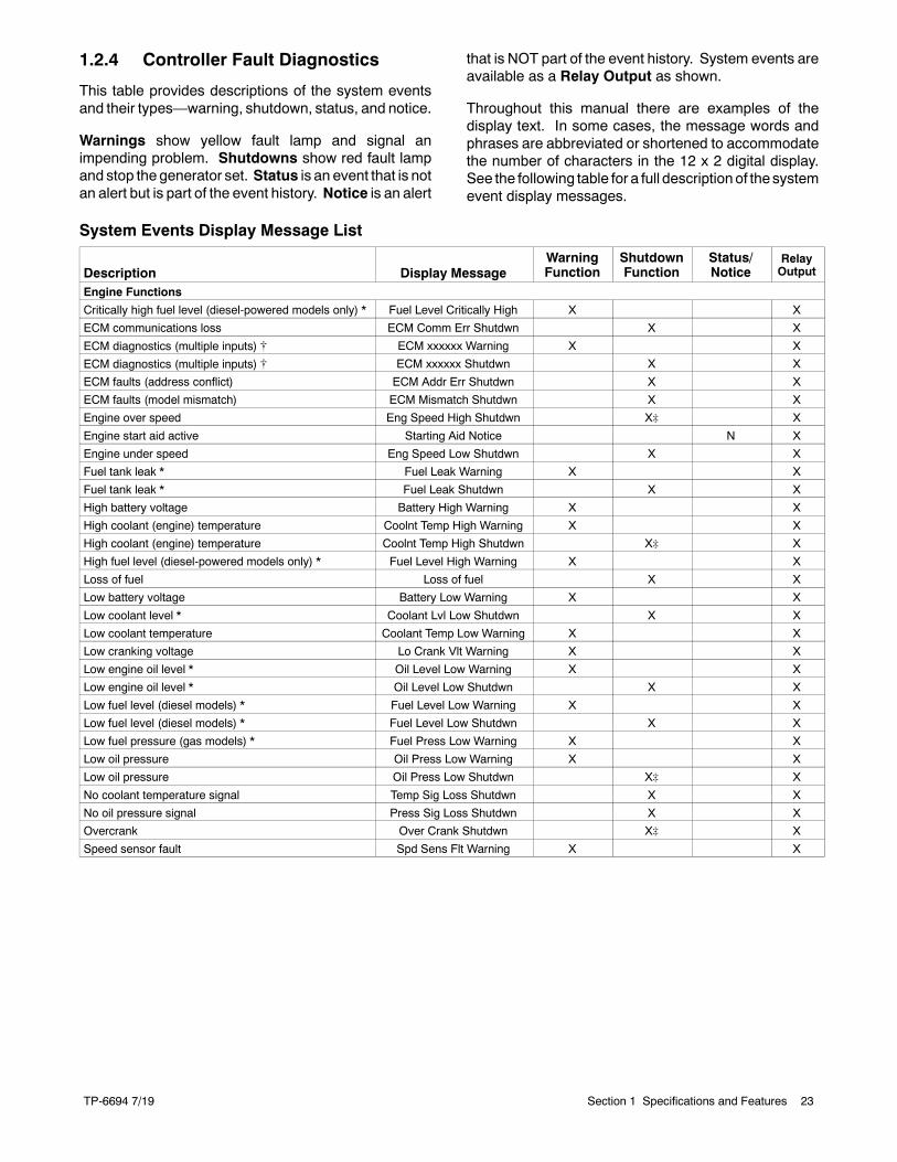
1.2.4 Controller Fault Diagnostics
This table provides descriptions of the system eventsand their types—warning, shutdown, status, and notice.
Warnings show yellow fault lamp and signal animpending problem. Shutdowns show red fault lampand stop the generator set. Status is an event that is notan alert but is part of the event history. Notice is an alert
that is NOT part of the event history. System events areavailable as a Relay Output as shown.
Throughout this manual there are examples of thedisplay text. In some cases, the message words andphrases are abbreviated or shortened to accommodatethe number of characters in the 12 x 2 digital display.See the following table for a full descriptionof the systemevent display messages.
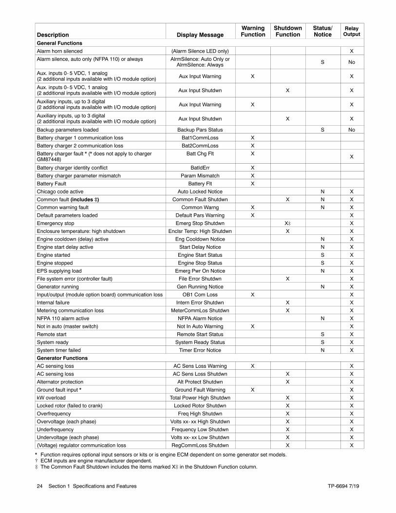
System Events Display Message List
Description Display MessageWarningFunction
ShutdownFunction
Status/Notice
RelayOutput
Engine Functions
Critically high fuel level (diesel-powered models only) * Fuel Level Critically High X X
ECM communications loss ECM Comm Err Shutdwn X X
ECM diagnostics (multiple inputs) [ ECM xxxxxx Warning X X
ECM diagnostics (multiple inputs) [ ECM xxxxxx Shutdwn X X
ECM faults (address conflict) ECM Addr Err Shutdwn X X
ECM faults (model mismatch) ECM Mismatch Shutdwn X X
Engine over speed Eng Speed High Shutdwn X] X
Engine start aid active Starting Aid Notice N X
Engine under speed Eng Speed Low Shutdwn X X
Fuel tank leak * Fuel Leak Warning X X
Fuel tank leak * Fuel Leak Shutdwn X X
High battery voltage Battery High Warning X X
High coolant (engine) temperature Coolnt Temp High Warning X X
High coolant (engine) temperature Coolnt Temp High Shutdwn X] X
High fuel level (diesel-powered models only) * Fuel Level High Warning X X
Loss of fuel Loss of fuel X X
Low battery voltage Battery Low Warning X X
Low coolant level * Coolant Lvl Low Shutdwn X X
Low coolant temperature Coolant Temp Low Warning X X
Low cranking voltage Lo Crank Vlt Warning X X
Low engine oil level * Oil Level Low Warning X X
Low engine oil level * Oil Level Low Shutdwn X X
Low fuel level (diesel models) * Fuel Level Low Warning X X
Low fuel level (diesel models) * Fuel Level Low Shutdwn X X
Low fuel pressure (gas models) * Fuel Press Low Warning X X
Low oil pressure Oil Press Low Warning X X
Low oil pressure Oil Press Low Shutdwn X] X
No coolant temperature signal Temp Sig Loss Shutdwn X X
No oil pressure signal Press Sig Loss Shutdwn X X
Overcrank Over Crank Shutdwn X] X
Speed sensor fault Spd Sens Flt Warning X X
TP-6694 7/1924 Section 1 Specifications and Features
DescriptionRelayOutput
Status/Notice
ShutdownFunction
WarningFunctionDisplay Message
General Functions
Alarm horn silenced (Alarm Silence LED only) X
Alarm silence, auto only (NFPA 110) or always AlrmSilence: Auto Only orAlrmSilence: Always S No
Aux. inputs 0- 5 VDC, 1 analog(2 additional inputs available with I/O module option) Aux Input Warning X X
Aux. inputs 0- 5 VDC, 1 analog(2 additional inputs available with I/O module option) Aux Input Shutdwn X X
Auxiliary inputs, up to 3 digital(2 additional inputs available with I/O module option) Aux Input Warning X X
Auxiliary inputs, up to 3 digital(2 additional inputs available with I/O module option) Aux Input Shutdwn X X
Backup parameters loaded Backup Pars Status S No
Battery charger 1 communication loss Bat1CommLoss X
Battery charger 2 communication loss Bat2CommLoss X
Battery charger fault * (* does not apply to chargerGM87448)
Batt Chg Flt XX
Battery charger identity conflict BatIdErr X
Battery charger parameter mismatch Param Mismatch X
Battery Fault Battery Flt X
Chicago code active Auto Locked Notice N X
Common fault (includes ]) Common Fault Shutdwn X N X
Common warning fault Common Warng X N X
Default parameters loaded Default Pars Warning X X
Emergency stop Emerg Stop Shutdwn X] X
Enclosure temperature: high shutdown Enclsr Temp: High Shutdwn X X
Engine cooldown (delay) active Eng Cooldown Notice N X
Engine start delay active Start Delay Notice N X
Engine started Engine Start Status S X
Engine stopped Engine Stop Status S X
EPS supplying load Emerg Pwr On Notice N X
File system error (controller fault) File Error Shutdwn X X
Generator running Gen Running Notice N X
Input/output (module option board) communication loss OB1 Com Loss X X
Internal failure Intern Error Shutdwn X X
Metering communication loss MeterCommLos Shutdwn X X
NFPA 110 alarm active NFPA Alarm Notice N X
Not in auto (master switch) Not In Auto Warning X X
Remote start Remote Start Status S X
System ready System Ready Status S X
System timer failed Timer Error Notice N X
Generator Functions
AC sensing loss AC Sens Loss Warning X X
AC sensing loss AC Sens Loss Shutdwn X X
Alternator protection Alt Protect Shutdwn X X
Ground fault input * Ground Fault Warning X X
kW overload Total Power High Shutdwn X X
Locked rotor (failed to crank) Locked Rotor Shutdwn X X
Overfrequency Freq High Shutdwn X X
Overvoltage (each phase) Volts xx- xx High Shutdwn X X
Underfrequency Frequency Low Shutdwn X X
Undervoltage (each phase) Volts xx- xx Low Shutdwn X X
(Voltage) regulator communication loss RegCommLoss Shutdwn X X
* Function requires optional input sensors or kits or is engine ECM dependent on some generator set models.[ ECM inputs are engine manufacturer dependent.] The Common Fault Shutdown includes the items marked X] in the Shutdown Function column.
TP-6694 7/19 25Section 1 Specifications and Features
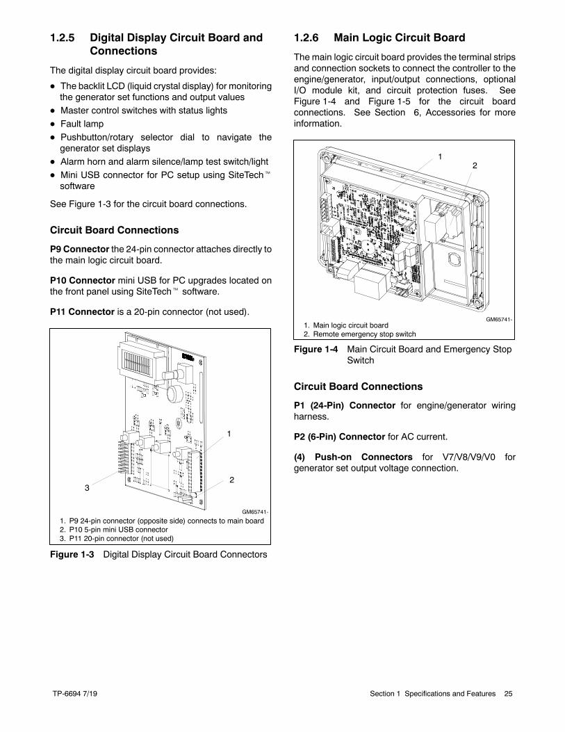
1.2.5 Digital Display Circuit Board andConnections
The digital display circuit board provides:
D The backlit LCD (liquid crystal display) for monitoringthe generator set functions and output values
D Master control switches with status lights
D Fault lamp
D Pushbutton/rotary selector dial to navigate thegenerator set displays
D Alarm horn and alarm silence/lamp test switch/light
D Mini USB connector for PC setup using SiteTechtsoftware
See Figure 1-3 for the circuit board connections.
Circuit Board Connections
P9 Connector the 24-pin connector attaches directly tothe main logic circuit board.
P10 Connector mini USB for PC upgrades located onthe front panel using SiteTecht software.
P11 Connector is a 20-pin connector (not used).
1. P9 24-pin connector (opposite side) connects to main board2. P10 5-pin mini USB connector3. P11 20-pin connector (not used)
GM65741-
1
23
Figure 1-3 Digital Display Circuit Board Connectors
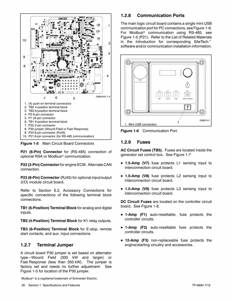
1.2.6 Main Logic Circuit Board
The main logic circuit board provides the terminal stripsand connection sockets to connect the controller to theengine/generator, input/output connections, optionalI/O module kit, and circuit protection fuses. SeeFigure 1-4 and Figure 1-5 for the circuit boardconnections. See Section 6, Accessories for moreinformation.
1. Main logic circuit board2. Remote emergency stop switch
GM65741-
12
Figure 1-4 Main Circuit Board and Emergency StopSwitch
Circuit Board Connections
P1 (24-Pin) Connector for engine/generator wiringharness.
P2 (6-Pin) Connector for AC current.
(4) Push-on Connectors for V7/V8/V9/V0 forgenerator set output voltage connection.
TP-6694 7/1926 Section 1 Specifications and Features
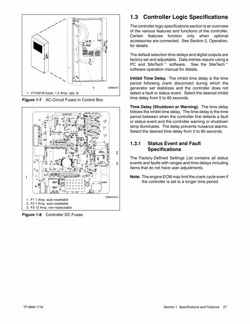
1. (4) push-on terminal connectors2. TB2 4-position terminal block3. TB3 6-position terminal block4. P2 6-pin connector5. P1 24-pin connector6. TB1 6-position terminal block7. P22 3-pin connector8. P30 jumper (Wound Field or Fast Response)9. P23 8-pin connector (RJ45)10. P21 6-pin connector (for RS-485 communication)
GM64345-1-A
1
2
3
4
56
10
7
9
8
Figure 1-5 Main Circuit Board Connectors
P21 (6-Pin) Connector for (RS-485) connection ofoptional RSA or Modbusr communication.
P22 (3-Pin) Connector for engineECM. AlternateCANconnection.
P23 (8-Pin) Connector (RJ45) for optional input/output(I/O) module circuit board.
Refer to Section 6.2, Accessory Connections forspecific connections of the following terminal blockconnections.
TB1 (6-Position) Terminal Block for analog and digitalinputs.
TB2 (4-Position) Terminal Block for K1 relay outputs.
TB3 (6-Position) Terminal Block for E-stop, remotestart contacts, and aux. input connections.
1.2.7 Terminal Jumper
A circuit board P30 jumper is set based on alternatortype—Wound Field (300 kW and larger) orFast Response (less than 350 kW). The jumper isfactory set and needs no further adjustment. SeeFigure 1-5 for location of the P30 jumper.
1.2.8 Communication Ports
The main logic circuit board contains a single mini USBcommunication port for PCconnections, seeFigure 1-6.For Modbusr communication using RS-485, seeFigure 1-5 (P21). Refer to the List of Related Materialsin the Introduction for corresponding SiteTechtsoftware and/or communication installation information.
1. Mini USB connectionGM65741-
1
Figure 1-6 Communication Port
1.2.9 Fuses
AC Circuit Fuses (TB5). Fuses are located inside thegenerator set control box. See Figure 1-7
D 1.5-Amp (V7) fuse protects L1 sensing input tointerconnection circuit board.
D 1.5-Amp (V8) fuse protects L2 sensing input tointerconnection circuit board.
D 1.5-Amp (V9) fuse protects L3 sensing input tointerconnection circuit board.
DC Circuit Fuses are located on the controller circuitboard. See Figure 1-8.
D 1-Amp (F1) auto-resettable, fuse protects thecontroller circuits.
D 1-Amp (F2) auto-resettable fuse protects thecontroller circuits.
D 12-Amp (F3) non-replaceable fuse protects theengine/starting circuitry and accessories.
Modbusr is a registered trademark of Schneider Electric.
TP-6694 7/19 27Section 1 Specifications and Features
1. V7/V8/V9 fuses, 1.5 Amp. (qty. 3)
GM694071
Figure 1-7 AC Circuit Fuses in Control Box
1. F1 1 Amp. auto-resettable2. F2 1 Amp. auto-resettable3. F3 12 Amp. non-replaceable
GM64345-C
1
2
3
Figure 1-8 Controller DC Fuses
1.3 Controller Logic Specifications
The controller logic specifications section is an overviewof the various features and functions of the controller.Certain features function only when optionalaccessories are connected. See Section 2, Operation,for details.
The default selection time delays and digital outputs arefactory set and adjustable. Data entries require using aPC and SiteTecht software. See the SiteTechtsoftware operation manual for details.
Inhibit Time Delay. The inhibit time delay is the timeperiod following crank disconnect during which thegenerator set stabilizes and the controller does notdetect a fault or status event. Select the desired inhibittime delay from 0 to 60 seconds.
TIme Delay (Shutdown or Warning). The time delayfollows the inhibit time delay. The time delay is the timeperiod between when the controller first detects a faultor status event and the controller warning or shutdownlamp illuminates. The delay prevents nuisance alarms.Select the desired time delay from 0 to 60 seconds.
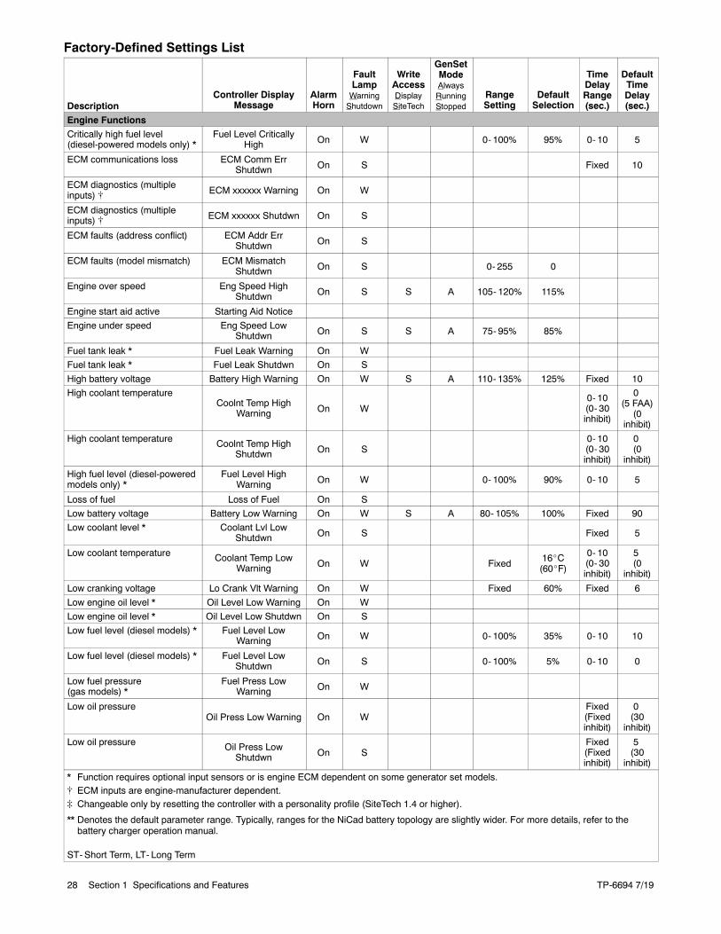
1.3.1 Status Event and FaultSpecifications
The Factory-Defined Settings List contains all statusevents and faults with ranges and time delays includingitems that do not have user adjustments.
Note: The engine ECMmay limit the crank cycle even ifthe controller is set to a longer time period.
TP-6694 7/1928 Section 1 Specifications and Features
Factory-Defined Settings List
DescriptionController Display
MessageAlarmHorn
FaultLampWarningShutdown
WriteAccessDisplaySiteTech
GenSetModeAlwaysRunningStopped
RangeSetting
DefaultSelection
TimeDelayRange(sec.)
DefaultTimeDelay(sec.)
Engine FunctionsCritically high fuel level(diesel-powered models only) *
Fuel Level CriticallyHigh On W 0- 100% 95% 0- 10 5
ECM communications loss ECM Comm ErrShutdwn On S Fixed 10
ECM diagnostics (multipleinputs) [ ECM xxxxxx Warning On W
ECM diagnostics (multipleinputs) [ ECM xxxxxx Shutdwn On S
ECM faults (address conflict) ECM Addr ErrShutdwn On S
ECM faults (model mismatch) ECM MismatchShutdwn On S 0- 255 0
Engine over speed Eng Speed HighShutdwn On S S A 105- 120% 115%
Engine start aid active Starting Aid Notice
Engine under speed Eng Speed LowShutdwn On S S A 75- 95% 85%
Fuel tank leak * Fuel Leak Warning On W
Fuel tank leak * Fuel Leak Shutdwn On S
High battery voltage Battery High Warning On W S A 110- 135% 125% Fixed 10
High coolant temperatureCoolnt Temp High
Warning On W0- 10(0- 30inhibit)
0(5 FAA)
(0inhibit)
High coolant temperature Coolnt Temp HighShutdwn On S
0- 10(0- 30inhibit)
0(0
inhibit)
High fuel level (diesel-poweredmodels only) *
Fuel Level HighWarning On W 0- 100% 90% 0- 10 5
Loss of fuel Loss of Fuel On S
Low battery voltage Battery Low Warning On W S A 80- 105% 100% Fixed 90
Low coolant level * Coolant Lvl LowShutdwn On S Fixed 5
Low coolant temperature Coolant Temp LowWarning On W Fixed
16_C(60_F)
0- 10(0- 30inhibit)
5(0
inhibit)
Low cranking voltage Lo Crank Vlt Warning On W Fixed 60% Fixed 6
Low engine oil level * Oil Level Low Warning On W
Low engine oil level * Oil Level Low Shutdwn On S
Low fuel level (diesel models) * Fuel Level LowWarning On W 0- 100% 35% 0- 10 10
Low fuel level (diesel models) * Fuel Level LowShutdwn On S 0- 100% 5% 0- 10 0
Low fuel pressure(gas models) *
Fuel Press LowWarning On W
Low oil pressureOil Press Low Warning On W
Fixed(Fixedinhibit)
0(30
inhibit)
Low oil pressure Oil Press LowShutdwn On S
Fixed(Fixedinhibit)
5(30
inhibit)
* Function requires optional input sensors or is engine ECM dependent on some generator set models.[ ECM inputs are engine-manufacturer dependent.] Changeable only by resetting the controller with a personality profile (SiteTech 1.4 or higher).
** Denotes the default parameter range. Typically, ranges for the NiCad battery topology are slightly wider. For more details, refer to thebattery charger operation manual.
ST- Short Term, LT- Long Term
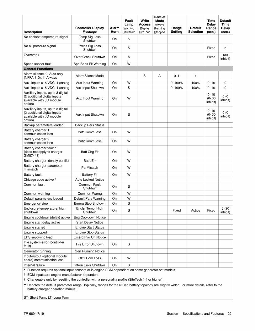
TP-6694 7/19 29Section 1 Specifications and Features
Description
DefaultTimeDelay(sec.)
TimeDelayRange(sec.)
DefaultSelection
RangeSetting
GenSetModeAlwaysRunningStopped
WriteAccessDisplaySiteTech
FaultLampWarningShutdown
AlarmHorn
Controller DisplayMessage
No coolant temperature signal Temp Sig LossShutdwn On S
No oil pressure signal Press Sig LossShutdwn On S Fixed 5
OvercrankOver Crank Shutdwn On S Fixed
(30inhibit)
Speed sensor fault Spd Sens Flt Warning On W
General FunctionsAlarm silence, 0- Auto only(NFPA 110), 1- Always AlarmSilenceMode S A 0- 1 1
Aux. inputs 0- 5 VDC, 1 analog Aux Input Warning On W 0- 100% 100% 0- 10 0
Aux. inputs 0- 5 VDC, 1 analog Aux Input Shutdwn On S 0- 100% 100% 0- 10 0
Auxiliary inputs, up to 3 digital(2 additional digital inputsavailable with I/O moduleoption)
Aux Input Warning On W0- 10(0- 30inhibit)
0 (0inhibit)
Auxiliary inputs, up to 3 digital(2 additional digital inputsavailable with I/O moduleoption)
Aux Input Shutdwn On S0- 10(0- 30inhibit)
0 (0inhibit)
Backup parameters loaded Backup Pars Status
Battery charger 1communication loss Bat1CommLoss On W
Battery charger 2communication loss Bat2CommLoss On W
Battery charger fault *(does not apply to chargerGM87448)
Batt Chg Flt On W
Battery charger identity conflict BatIdErr On W
Battery charger parametermismatch ParMisatch On W
Battery fault Battery Flt On W
Chicago code active * Auto Locked Notice
Common fault Common FaultShutdwn On S
Common warning Common Warng On W
Default parameters loaded Default Pars Warning On W
Emergency stop Emerg Stop Shutdwn On S
Enclosure temperature: highshutdown
Enclsr Temp: HighShutdwn On S Fixed Active Fixed
5 (20inhibit)
Engine cooldown (delay) active Eng Cooldown Notice
Engine start delay active Start Delay Notice
Engine started Engine Start Status
Engine stopped Engine Stop Status
EPS supplying load Emerg Pwr On Notice
File system error (controllerfault) File Error Shutdwn On S
Generator running Gen Running Notice
Input/output (optional moduleboard) communication loss OB1 Com Loss On W
Internal failure Intern Error Shutdwn On S* Function requires optional input sensors or is engine ECM dependent on some generator set models.[ ECM inputs are engine-manufacturer dependent.] Changeable only by resetting the controller with a personality profile (SiteTech 1.4 or higher).
** Denotes the default parameter range. Typically, ranges for the NiCad battery topology are slightly wider. For more details, refer to thebattery charger operation manual.
ST- Short Term, LT- Long Term
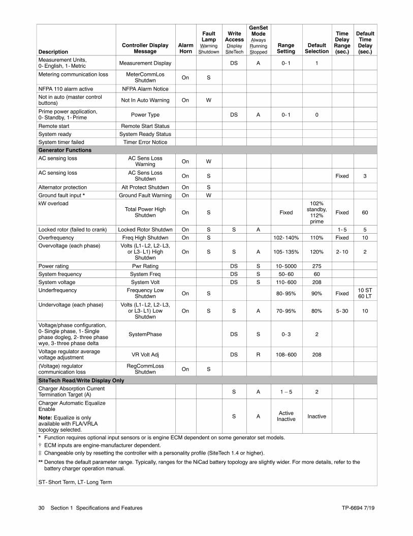
TP-6694 7/1930 Section 1 Specifications and Features
Description
DefaultTimeDelay(sec.)
TimeDelayRange(sec.)
DefaultSelection
RangeSetting
GenSetModeAlwaysRunningStopped
WriteAccessDisplaySiteTech
FaultLampWarningShutdown
AlarmHorn
Controller DisplayMessage
Measurement Units,0- English, 1-Metric Measurement Display DS A 0- 1 1
Metering communication loss MeterCommLosShutdwn On S
NFPA 110 alarm active NFPA Alarm Notice
Not in auto (master controlbuttons) Not In Auto Warning On W
Prime power application,0- Standby, 1- Prime Power Type DS A 0- 1 0
Remote start Remote Start Status
System ready System Ready Status
System timer failed Timer Error Notice
Generator Functions
AC sensing loss AC Sens LossWarning On W
AC sensing loss AC Sens LossShutdwn On S Fixed 3
Alternator protection Alt Protect Shutdwn On S
Ground fault input * Ground Fault Warning On W
kW overloadTotal Power High
Shutdwn On S Fixed
102%standby,112%prime
Fixed 60
Locked rotor (failed to crank) Locked Rotor Shutdwn On S S A 1- 5 5
Overfrequency Freq High Shutdwn On S 102- 140% 110% Fixed 10
Overvoltage (each phase) Volts (L1- L2, L2- L3,or L3- L1) High
ShutdwnOn S S A 105- 135% 120% 2- 10 2
Power rating Pwr Rating DS S 10- 5000 275
System frequency System Freq DS S 50- 60 60
System voltage System Volt DS S 110- 600 208
Underfrequency Frequency LowShutdwn On S 80- 95% 90% Fixed
10 ST60 LT
Undervoltage (each phase) Volts (L1- L2, L2- L3,or L3- L1) Low
ShutdwnOn S S A 70- 95% 80% 5- 30 10
Voltage/phase configuration,0- Single phase, 1- Singlephase dogleg, 2- three phasewye, 3- three phase delta
SystemPhase DS S 0- 3 2
Voltage regulator averagevoltage adjustment VR Volt Adj DS R 108- 600 208
(Voltage) regulatorcommunication loss
RegCommLossShutdwn On S
SiteTech Read/Write Display OnlyCharger Absorption CurrentTermination Target (A) S A 1 – 5 2
Charger Automatic EqualizeEnable
Note: Equalize is onlyavailable with FLA/VRLAtopology selected.
S AActiveInactive Inactive
* Function requires optional input sensors or is engine ECM dependent on some generator set models.[ ECM inputs are engine-manufacturer dependent.] Changeable only by resetting the controller with a personality profile (SiteTech 1.4 or higher).
** Denotes the default parameter range. Typically, ranges for the NiCad battery topology are slightly wider. For more details, refer to thebattery charger operation manual.
ST- Short Term, LT- Long Term
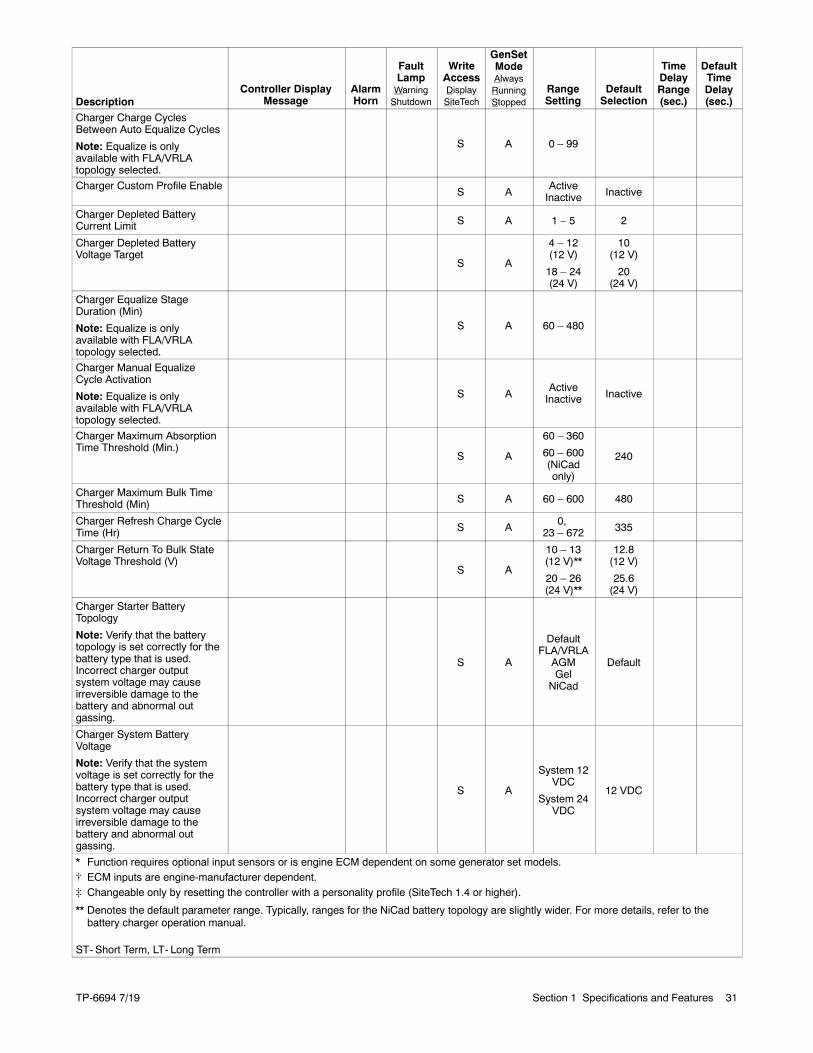
TP-6694 7/19 31Section 1 Specifications and Features
Description
DefaultTimeDelay(sec.)
TimeDelayRange(sec.)
DefaultSelection
RangeSetting
GenSetModeAlwaysRunningStopped
WriteAccessDisplaySiteTech
FaultLampWarningShutdown
AlarmHorn
Controller DisplayMessage
Charger Charge CyclesBetween Auto Equalize Cycles
Note: Equalize is onlyavailable with FLA/VRLAtopology selected.
S A 0 – 99
Charger Custom Profile EnableS A
ActiveInactive Inactive
Charger Depleted BatteryCurrent Limit S A 1 – 5 2
Charger Depleted BatteryVoltage Target
S A
4 – 12(12 V)
18 – 24(24 V)
10(12 V)
20(24 V)
Charger Equalize StageDuration (Min)
Note: Equalize is onlyavailable with FLA/VRLAtopology selected.
S A 60 – 480
Charger Manual EqualizeCycle Activation
Note: Equalize is onlyavailable with FLA/VRLAtopology selected.
S AActiveInactive Inactive
Charger Maximum AbsorptionTime Threshold (Min.)
S A
60 – 360
60 – 600(NiCadonly)
240
Charger Maximum Bulk TimeThreshold (Min) S A 60 – 600 480
Charger Refresh Charge CycleTime (Hr) S A
0,23 – 672 335
Charger Return To Bulk StateVoltage Threshold (V)
S A
10 – 13(12 V)**
20 – 26(24 V)**
12.8(12 V)
25.6(24 V)
Charger Starter BatteryTopology
Note: Verify that the batterytopology is set correctly for thebattery type that is used.Incorrect charger outputsystem voltage may causeirreversible damage to thebattery and abnormal outgassing.
S A
DefaultFLA/VRLA
AGMGel
NiCad
Default
Charger System BatteryVoltage
Note: Verify that the systemvoltage is set correctly for thebattery type that is used.Incorrect charger outputsystem voltage may causeirreversible damage to thebattery and abnormal outgassing.
S A
System 12VDC
System 24VDC
12 VDC
* Function requires optional input sensors or is engine ECM dependent on some generator set models.[ ECM inputs are engine-manufacturer dependent.] Changeable only by resetting the controller with a personality profile (SiteTech 1.4 or higher).
** Denotes the default parameter range. Typically, ranges for the NiCad battery topology are slightly wider. For more details, refer to thebattery charger operation manual.
ST- Short Term, LT- Long Term
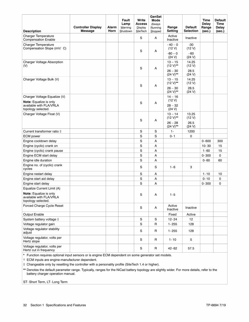
TP-6694 7/1932 Section 1 Specifications and Features
Description
DefaultTimeDelay(sec.)
TimeDelayRange(sec.)
DefaultSelection
RangeSetting
GenSetModeAlwaysRunningStopped
WriteAccessDisplaySiteTech
FaultLampWarningShutdown
AlarmHorn
Controller DisplayMessage
Charger TemperatureCompensation Enable S A
ActiveInactive Inactive
Charger TemperatureCompensation Slope (mV/ C)
S A
- 40 – 0(12 V)
-80 – 0(24 V)
-30(12 V)
- 60(24 V)
Charger Voltage Absorption(V)
S A
13 – 15(12 V)**
26 – 30(24 V)**
14.25(12 V)
28.5(24 V)
Charger Voltage Bulk (V)
S A
13 – 15(12 V)**
26 – 30(24 V)**
14.25(12 V)
28.5(24 V)
Charger Voltage Equalize (V)
Note: Equalize is onlyavailable with FLA/VRLAtopology selected.
S A
14 – 16(12 V)
28 – 32(24 V)
Charger Voltage Float (V)
S A
13 – 14(12 V)**
26 – 28(24 V)**
13.25(12 V)
26.5(24 V)
Current transformer ratio ] S S 1- 1200
ECM power S S 0- 1 0
Engine cooldown delay S A 0- 600 300
Engine (cyclic) crank on S A 10- 30 15
Engine (cyclic) crank pause S A 1- 60 15
Engine ECM start delay S A 0- 300 0
Engine idle duration S A 0- 60 60
Engine no. of (cyclic) crankcycles S S 1- 6 3
Engine restart delay S A 1- 10 10
Engine start aid delay S A 0- 10 0
Engine start delay S A 0- 300 0
Equalize Current Limit (A)
Note: Equalize is onlyavailable with FLA/VRLAtopology selected.
S A 1–5
Forced Charge Cycle ResetS A
ActiveInactive Inactive
Output Enable Fixed Active
System battery voltage ] S S 12- 24 12
Voltage regulator gain S R 1- 255 128
Voltage regulator stabilityadjust S R 1- 255 128
Voltage regulator, volts perHertz slope S R 1- 10 5
Voltage regulator, volts perHertz cut in frequency S R 42- 62 57.5
* Function requires optional input sensors or is engine ECM dependent on some generator set models.[ ECM inputs are engine-manufacturer dependent.] Changeable only by resetting the controller with a personality profile (SiteTech 1.4 or higher).
** Denotes the default parameter range. Typically, ranges for the NiCad battery topology are slightly wider. For more details, refer to thebattery charger operation manual.
ST- Short Term, LT- Long Term
TP-6694 7/19 33Section 1 Specifications and Features
1.3.2 Voltage Regulator and CalibrationSpecifications
The controller has a voltage regulation function that isinternal to the processor. This means that no externalvoltage regulator is necessary. The voltage regulationof the controller uses root mean square (rms) sensingfor fast response to changes in indicated and regulatedvoltages resulting in excellent regulation accuracy.
1.3.3 Voltage Regulator Adjustments
The descriptions of the voltage regulator adjustmentsand features follow. Refer to the Factory-DefinedSettings List shown in 1.3.1 for voltage regulatoradjustments. See Appendix C, Voltage RegulatorDefinitions and Adjustments, for additional informationand to customize adjustments for specific applications.
Voltage Adjustment. The voltage adjustment allowsthe user to enter the desired generator set output level.This regulated level setting is the average of the threeline-to-line voltages in three-phase configurations orL1-to-L2 in single phase configurations.
Submenus display the individual line-to-line voltages.These voltages are for reference only and are relevantin unbalanced load conditions. The voltage adjustsetpoint can be changed to accommodate an importantphase in an unbalanced system.
Underfrequency Unload Frequency Setpoint. Thisadjustment affects the voltagedroop (volts perHz)whenload is applied and underfrequency occurs. Theunderfrequency unload setting defines the setpointwhere underfrequency starts. Any frequency below thesetpoint causes the voltage to drop thus reducing theload allowing the engine speed to recover according tothe underfrequency unload slope setting.
Engine speed recovery depends upon characteristicssuch as engine make, fuel type, load types, andoperating conditions. The underfrequency unloadsetting should match the engine speed recoverycharacteristics for the application.
Underfrequency Unload Slope. This settingdetermines how much the voltage drops during anunderfrequency condition. Typically, applying a largeelectrical load causes a dip in engine speed andfrequency. The voltage regulator reduces voltage,allowing engine speed recovery. The volts-per-Hzsetting determines the amount of voltage drop.
RegulatorGain. Regulator gain refers to the gain of thecontrol system. Generally, the higher the gain the fasterthe system responds to changes and the lower the gain,the more stable the system.
If the voltage is slow to recover when loads are appliedor removed, increase the regulator gain. If the voltage isunstable, decrease the regulator gain.

TP-6694 7/1934 Section 1 Specifications and Features
Notes
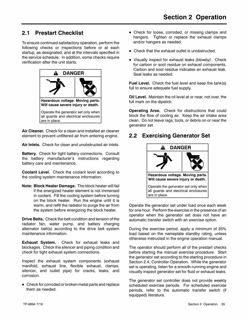
TP-6694 7/19 35Section 2 Operation
Section 2 Operation
2.1 Prestart Checklist
To ensure continued satisfactory operation, perform thefollowing checks or inspections before or at eachstartup, as designated, and at the intervals specified inthe service schedule. In addition, some checks requireverification after the unit starts.
Hazardous voltage. Moving parts.Will cause severe injury or death.
Operate the generator set only whenall guards and electrical enclosuresare in place.
DANGER
Air Cleaner. Check for a clean and installed air cleanerelement to prevent unfiltered air from entering engine.
Air Inlets. Check for clean and unobstructed air inlets.
Battery. Check for tight battery connections. Consultthe battery manufacturer’s instructions regardingbattery care and maintenance.
Coolant Level. Check the coolant level according tothe cooling system maintenance information.
Note: Block Heater Damage. The block heater will failif the energized heater element is not immersedin coolant. Fill the cooling system before turningon the block heater. Run the engine until it iswarm, and refill the radiator to purge the air fromthe system before energizing the block heater.
DriveBelts. Check the belt condition and tension of theradiator fan, water pump, and battery chargingalternator belt(s) according to the drive belt systemmaintenance information.
Exhaust System. Check for exhaust leaks andblockages. Check the silencer and piping condition andcheck for tight exhaust system connections.
Inspect the exhaust system components (exhaustmanifold, exhaust line, flexible exhaust, clamps,silencer, and outlet pipe) for cracks, leaks, andcorrosion.
D Check for corroded or brokenmetal parts and replacethem as needed.
D Check for loose, corroded, or missing clamps andhangers. Tighten or replace the exhaust clampsand/or hangers as needed.
D Check that the exhaust outlet is unobstructed.
D Visually inspect for exhaust leaks (blowby). Checkfor carbon or soot residue on exhaust components.Carbon and soot residue indicates an exhaust leak.Seal leaks as needed.
Fuel Level. Check the fuel level and keep the tank(s)full to ensure adequate fuel supply.
Oil Level. Maintain the oil level at or near, not over, thefull mark on the dipstick.
Operating Area. Check for obstructions that couldblock the flow of cooling air. Keep the air intake areaclean. Do not leave rags, tools, or debris on or near thegenerator set.
2.2 Exercising Generator Set
Hazardous voltage. Moving parts.Will cause severe injury or death.
Operate the generator set only whenall guards and electrical enclosuresare in place.
DANGER
Operate the generator set under load once each weekfor one hour. Perform the exercise in the presence of anoperator when the generator set does not have anautomatic transfer switch with an exercise option.
During the exercise period, apply a minimum of 35%load based on the nameplate standby rating, unlessotherwise instructed in the engine operation manual.
The operator should perform all of the prestart checksbefore starting the manual exercise procedure. Startthe generator set according to the starting procedure inSection 2.4, Controller Operation. While the generatorset is operating, listen for a smooth-running engine andvisually inspect generator set for fluid or exhaust leaks.
The generator set controller does not provide weeklyscheduled exercise periods. For scheduled exerciseperiods, refer to the automatic transfer switch (ifequipped) literature.
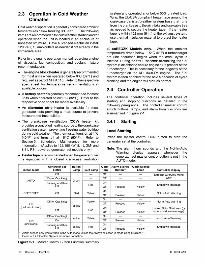
TP-6694 7/1936 Section 2 Operation
2.3 Operation in Cold WeatherClimates
Coldweather operation is generally considered ambienttemperatures below freezing 0C (32F). The followingitemsare recommended for coldweather starting and/oroperation when the unit is located in an enclosure orunheated structure. Have a licensed electrician install120 VAC, 15 amp outlets as needed if not already in theimmediate area.
Refer to the engine operation manual regarding engineoil viscosity, fuel composition, and coolant mixturerecommendations.
D The engine block heater is generally recommendedfor most units when operated below 0C (32F) andrequired as part of NFPA 110. Refer to the respectivespec sheet for temperature recommendations inavailable options.
D A battery heater is generally recommended for mostunits when operated below 0C (32F). Refer to therespective spec sheet for model availability.
D An alternator strip heater is available for mostgenerator sets providing a heat source to preventmoisture and frost buildup.
D The crankcase ventilation (CCV) heater kitprovides a controlled heating source to the crankcaseventilation system preventing freezing water buildupduring cold weather. The thermostat turns on at 4_C(40_F) and turns off at 16_C (60_F). Refer toSection 3, Scheduled Maintenance for moreinformation. (Applies to 125/150 kW, 8.1 L GM- and8.8 L PSI- powered generator set models only.)
D Heater tape is recommendedwhen the generator setis equipped with a closed crankcase ventilation
system and operated at or below 50% of rated load.Wrap the UL/CSA compliant heater tape around thecrankcase canister/breather system hose that runsfrom the crankcase to the air intake and use cable tiesas needed to secure the heater tape. If the heatertape is within 152 mm (6 in.) of the exhaust system,use thermal insulation material to protect the heatertape.
40- 60REOZK Models only. When the ambienttemperature drops below - 15_C (5_F) a turbochargerpre-lube sequence begins when the crank cycle isinitiated. During the first 10 seconds of cranking, the fuelsystem is disabled to ensure engine oil is present at theturbocharger. This is necessary for the longevity of theturbocharger on the KDI 3404TM engine. The fuelsystem is then enabled for the next 5 seconds of cycliccranking and the engine will start as normal.
2.4 Controller Operation
The controller operation includes several types ofstarting and stopping functions as detailed in thefollowing paragraphs. The controller master controlswitch buttons, lamps, and alarm horn functions aresummarized in Figure 2-1.
2.4.1 Starting
Local Starting
Press the master control RUN button to start thegenerator set at the controller.
Note: The alarm horn sounds and the Not-In-AutoWarning display appears whenever thegenerator set master control button is not in theAUTO mode.
Button ModeGenerator Set
StatusButtonLamp Fault Lamp
AlarmHorn
Alarm SilenceButton *
Alarm SilenceLamp Controller Display
AUTO
Off
Green
— Off — — Scrolling Overview MenuOnlyOn (or Cranking) — Off — —
Running and thenOff Red
On — —Shutdown Message
Off Pressed Yellow
OFF/RESET Off Red YellowOn — —
Not In Auto WarningOff Pressed Yellow
RUN(unit fails to start)
Off (or Cranking)
Yellow
YellowOn — —
Not in Auto WarningOff Pressed Yellow
Off RedOn — — Locked Rotor Shutdown (or
other shutdown message)Off Pressed Yellow
RUN(unit starts)
Off (or Cranking)Yellow Yellow
On — —Not in Auto Warming
On Off Pressed Yellow
Running and thenOff Yellow Red
On — —Shutdown Message
Off Pressed Yellow
* Alarm silence only works when in the Auto mode unless the Always selection is made using SiteTecht.Refer to 2.7.7 GenSet System for more information.
Figure 2-1 Master Control Button Function Summary
TP-6694 7/19 37Section 2 Operation
Note: The transient start/stop function of the controllerprevents accidental cranking of the rotating engine.The generator set stops and recranks when theOFF/RESET button is momentarily pressed andthen the RUN button is pressed.
Auto Starting
Press the master control AUTO button to allow startupby the automatic transfer switch or remote start/stopswitch (connected to controller terminals 3 and 4).
Terminals 3 and 4 connect to a circuit that automaticallystarts the generator set crank cycle when an externalsource closes the circuit.
Note: The controller provides up to 30 seconds ofprogrammable cyclic cranking and up to60 seconds rest with up to 6 cycles. The defaultsetting is 15 seconds cranking and 15 secondsrest for 3 cycles. Make cyclic crankingadjustments using SiteTecht software.
Prime Power Switch
The controller has an optional prime power mode ofoperation. The prime power mode requires installationof an optional prime power switch kit. See Section 6,Accessories, for instructions on how to install theoptional prime power switch kit. The prime power switchkit prevents engine starting battery drain when thegenerator set is shut down and no external batterycharging is available.
Move theprimepower switch locatedon the junctionboxto the CONTROLLER ON position before attempting tostart the generator set. When the prime power mode isoff, all controller functions including the digital display,LEDs, and alarm horn are operative.
Stop the generator set using the stopping procedures inSection 2.4.2 before placing the generator set in theprime power mode. Move the prime power switchlocated on the junction box to the CONTROLLER OFFposition. When the generator set is is the prime powermode, all controller functions including the digitaldisplay, LEDs, alarm horn, and communications areinoperative.
2.4.2 Stopping (User Stopping andFault Shutdown)
Normal Stopping
Run the generator set without load for 5 minutes toensure adequate engine cooldown.
The controller has a programmable cooldown timer thatfunctions only when the master control button is in theAUTO mode. To stop the generator set, press thegenerator set master control OFF/RESET button andwait until the generator set comes to a complete stop.
Note: The cooldown cycle times out before thegenerator set stops when a remote switch orautomatic transfer switch initiates the generatorset start/stop sequence.
Emergency Stopping
Use the controller emergency stop switch or optionalremote emergency stop for immediate shutdown.
The emergency stop switch bypasses the time delayengine cooldown and immediately shuts down thegenerator set.
Note: Use the emergency stop switch(es) foremergency shutdowns only. Use the generatorset master control OFF/RESET button for normalshutdowns.
The controller fault lamp lights and the unit shuts downwhen the local or remote emergency stop switchactivates.
2.4.3 Emergency Stop Switch Resetting
Use the following procedure to reset the generator setafter shutdown by a local or remote emergency stopswitch. Refer to Section 2.4.8, Controller Resettingprocedure, to restart the generator set following a faultshutdown.
1. Investigate and correct the cause of theemergency stop.
2. Reset the optional remote emergency stop switch byreplacing the glass piece,whenequipped. Additionalglass rods are available as a service part. Reset thecontroller emergency stop switch by pulling theswitch dial outward.
3. Press the generator set master controlOFF/RESET button.
4. After resetting all faults using the controller resetprocedure in Section 2.4.8, press the generator setmaster control RUN or AUTO button to restart thegenerator set. The generator set will not crank untilthe reset procedure completes.
TP-6694 7/1938 Section 2 Operation
2.4.4 System Status Lamps
The (OFF/RESET- AUTO-RUN)master control buttonsindicate the status condition with an integrated lamp atthe button.
The green lamp illuminates on themaster control AUTO(automatic start) button indicating the system senses nofaults and the unit is ready to start by remote command.
The red lamp illuminates on the master controlOFF/RESET button indicating the generator set isstopped.
The yellow lamp illuminates on the master control RUNbutton indicating the generator set is cranking or runningfrom a local command.
Only one of the three master control button lamps willilluminate at any given time.
2.4.5 System Fault Warning Lamp withDigital Displays
The system FAULT lamp glows yellow and the alarmhorn sounds indicating a warning fault but does not shutdown the generator set. The fault lamp illuminatesyellow and the alarm horn sounds when the fuel tanklevel on diesel-fueled models approaches empty. Thisfault requires an optional low fuel level switch for thelamp to function. The local display shows Fuel LevelLow Warning. See Section 2.4.8, Controller Resettingprocedure, for instructions on resetting a systemwarning.
When the system warning lamp is on and no messagedisplays, rotate the selector dial to view messages.When the system warning continues, it may lead to afault and cause a system shutdown.
Use the Silence Alarm button to silence the alarm hornat the operator’s discretion.
If the controller is setup for an NFPA 110 application,press the AUTO button before silencing the alarm horn.The alarm horn cannot be silenced unless the mastercontrol button is in the AUTO mode. See 2.4.7 Statusand Notice Digital Displays for more information.
Note: Text shown in italics in this section of the manualrepresents digital display messages.
AC Sensing Loss. The fault lamp illuminates yellowand the alarm horn sounds when the controller does notdetect the nominal generator set AC output voltage aftercrank disconnect. The controller displaysACSensLossWarning.
Auxiliary Input (Warning). The fault lamp illuminatesyellow and the alarm horn sounds when an auxiliarydigital or analog input signals the controller. The digitalinputs do not function during first the 30 seconds afterstartup. Use SiteTecht software to define inputs asshutdowns or warnings. The local display shows AuxInput Warning.
Battery Charger Communication Loss. The warningfault lamp on the controller illuminates yellow and thealarm horn sounds when CAN communication with thebattery charger has been lost. Local display showseither bat1CommLoss or bat2CommLoss.
Note: bat2CommLoss indicates communication lossfor battery charger number 2. bat2CommLoss isonly relevant for generator sets with more thanone battery charger.
Battery Charger Fault. Thewarning lamp on controllerilluminates yellow and the alarm horn sounds when thebattery charger malfunctions. Local display shows BattChg Flt.
Battery Charger Identity Conflict. The warning lampon the controller illuminates yellow and the alarm hornsounds when there is a CAN address communicationerror. The battery charger has the same CAN addressas another generator set component. To correct a CANaddress error, verify the address identification in theharness and power cycle the controller. Local displayshows BatIdErr.
Battery Charger Parameter Mismatch. The warninglamp on controller illuminates yellow and the alarm hornsounds when the battery charger metering is not inrange of the specified parameters. Local display showsParMisatch.
Battery Fault. The warning lamp on controllerilluminates yellow and the alarm horn sounds whenthere is an issue with the battery such as a connectionproblem or a dead battery. When the temperaturecompensation sensor is connected, whether active orinactive, and the temperature rises above 60_C (140_F)or below - 20_C (- 4_F), the battery failure warning willalso be displayed indicating that the battery is unable totake charge due to temperature. Absorption timeout willalso cause a failure since the battery was unable toaccept the expected charge in the time frame givenwhich indicates a potential battery issue. Local displayshows Battery Flt.
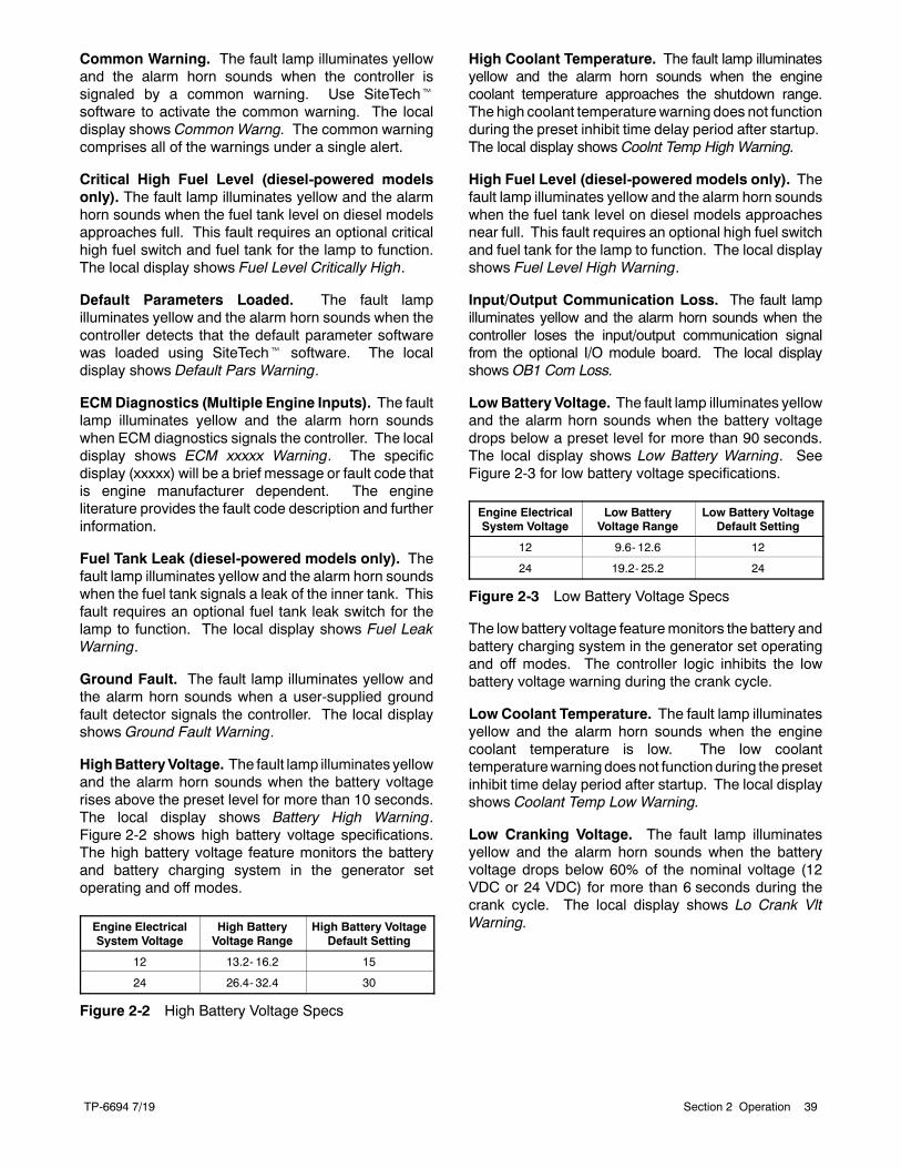
TP-6694 7/19 39Section 2 Operation
Common Warning. The fault lamp illuminates yellowand the alarm horn sounds when the controller issignaled by a common warning. Use SiteTechtsoftware to activate the common warning. The localdisplay shows Common Warng. The common warningcomprises all of the warnings under a single alert.
Critical High Fuel Level (diesel-powered modelsonly). The fault lamp illuminates yellow and the alarmhorn sounds when the fuel tank level on diesel modelsapproaches full. This fault requires an optional criticalhigh fuel switch and fuel tank for the lamp to function.The local display shows Fuel Level Critically High.
Default Parameters Loaded. The fault lampilluminates yellow and the alarm horn sounds when thecontroller detects that the default parameter softwarewas loaded using SiteTecht software. The localdisplay shows Default Pars Warning.
ECMDiagnostics (Multiple Engine Inputs). The faultlamp illuminates yellow and the alarm horn soundswhen ECM diagnostics signals the controller. The localdisplay shows ECM xxxxx Warning. The specificdisplay (xxxxx) will be a brief message or fault code thatis engine manufacturer dependent. The engineliterature provides the fault code description and furtherinformation.
Fuel Tank Leak (diesel-powered models only). Thefault lamp illuminates yellow and the alarm horn soundswhen the fuel tank signals a leak of the inner tank. Thisfault requires an optional fuel tank leak switch for thelamp to function. The local display shows Fuel LeakWarning.
Ground Fault. The fault lamp illuminates yellow andthe alarm horn sounds when a user-supplied groundfault detector signals the controller. The local displayshows Ground Fault Warning.
HighBatteryVoltage. The fault lamp illuminates yellowand the alarm horn sounds when the battery voltagerises above the preset level for more than 10 seconds.The local display shows Battery High Warning.Figure 2-2 shows high battery voltage specifications.The high battery voltage feature monitors the batteryand battery charging system in the generator setoperating and off modes.
Engine ElectricalSystem Voltage
High BatteryVoltage Range
High Battery VoltageDefault Setting
12 13.2- 16.2 15
24 26.4- 32.4 30
Figure 2-2 High Battery Voltage Specs
High Coolant Temperature. The fault lamp illuminatesyellow and the alarm horn sounds when the enginecoolant temperature approaches the shutdown range.The high coolant temperaturewarning does not functionduring the preset inhibit time delay period after startup.The local display shows Coolnt Temp High Warning.
High Fuel Level (diesel-powered models only). Thefault lamp illuminates yellow and the alarm horn soundswhen the fuel tank level on diesel models approachesnear full. This fault requires an optional high fuel switchand fuel tank for the lamp to function. The local displayshows Fuel Level High Warning.
Input/Output Communication Loss. The fault lampilluminates yellow and the alarm horn sounds when thecontroller loses the input/output communication signalfrom the optional I/O module board. The local displayshows OB1 Com Loss.
LowBattery Voltage. The fault lamp illuminates yellowand the alarm horn sounds when the battery voltagedrops below a preset level for more than 90 seconds.The local display shows Low Battery Warning. SeeFigure 2-3 for low battery voltage specifications.
Engine ElectricalSystem Voltage
Low BatteryVoltage Range
Low Battery VoltageDefault Setting
12 9.6- 12.6 12
24 19.2- 25.2 24
Figure 2-3 Low Battery Voltage Specs
The low battery voltage featuremonitors the battery andbattery charging system in the generator set operatingand off modes. The controller logic inhibits the lowbattery voltage warning during the crank cycle.
Low Coolant Temperature. The fault lamp illuminatesyellow and the alarm horn sounds when the enginecoolant temperature is low. The low coolanttemperaturewarningdoesnot function during the presetinhibit time delay period after startup. The local displayshows Coolant Temp Low Warning.
Low Cranking Voltage. The fault lamp illuminatesyellow and the alarm horn sounds when the batteryvoltage drops below 60% of the nominal voltage (12VDC or 24 VDC) for more than 6 seconds during thecrank cycle. The local display shows Lo Crank VltWarning.
TP-6694 7/1940 Section 2 Operation
Low Engine Oil Level. The fault lamp illuminatesyellow and the alarm horn sounds because of lowengine oil level. This fault feature requires an optionallowengineoil level sensor for the lamp to function. Localdisplay shows Oil Level Low Warning.
Low Fuel Level (diesel-powered models only). Thefault lamp illuminates yellow and the alarm horn soundswhen the fuel tank level on diesel-fueled modelsapproaches empty. This fault requires an optional lowfuel level switch for the lamp to function. The localdisplay shows Fuel Level Low Warning.
Low Fuel Pressure (gas-poweredmodels only). Thefault lamp illuminates yellow and the alarm horn soundswhen low fuel pressure on gaseous-fueled modelsoccurs. This fault requires an optional low fuel pressureswitch for the lamp to function. The local display showsFuel Press Low Warning.
Low Oil Pressure. The fault lamp illuminates yellowand the alarm horn soundswhen the engine oil pressureapproaches the shutdown range. The low oil pressurewarning does not function during first the 30 secondsafter startup. The local display shows Oil Press LowWarning.
Not in Auto (Generator Master Control Switches).The fault lamp illuminates yellow and the alarm hornsounds when the generator set master control button isin the RUN or OFF/RESET mode. The local displayshows Not In Auto Warning.
Speed Sensor Fault. The fault lamp illuminates yellowand the alarm horn sounds when the speed signal isabsent for one secondwhile the generator set runs. Thelocal display shows Spd Sens Flt Warning.
2.4.6 System Fault Shutdown LampWith Digital Displays
The system FAULT lamp glows red, the alarm hornsounds, and the unit shuts down to indicate a faultshutdown under the following conditions. See Section2.4.8,ControllerResetting procedure, for information onresetting a system shutdown.
Use the AlarmOff button to silence the alarm horn at theoperator’s discretion.
If the controller is set up for an NFPA 110 application,press the AUTO button before silencing the alarm horn.The alarm horn cannot be silenced unless the mastercontrol button is in the AUTO mode. See 2.4.7 Statusand Notice Digital Displays for more information.
Note: Text shown in italics in this section of the manualrepresents digital display messages.
AC Sensing Loss. The fault lamp illuminates red, thealarm horn sounds, and the unit shuts down when thecontroller does not detect the nominal generator set ACoutput voltage for more than 3 seconds after crankdisconnect. The controller displays AC Sens LossShutdwn.
Alternator Protection. The fault lamp illuminates redand the unit shuts down because of an alternatoroverload or short circuit. The local display shows AltProtect Shutdwn. See Appendix D, AlternatorProtection for more information.
Auxiliary Input (Shutdown). The fault lampilluminates red, the alarm horn sounds, and the unitshuts down when an auxiliary digital or analog inputssignals the controller. The digital inputs do not functionduring first the 30 seconds after startup. UseSiteTechtsoftware to define inputs as shutdowns or warnings.The local display shows Aux Input Shutdwn.
Common Fault. The fault lamp illuminates red, thealarm horn sounds, and the unit shuts down when thecontroller is signaled by a common fault. UseSiteTecht software to activate the common faultshutdown. The local display shows Common FaultShutdwn. The common fault comprises the followingshutdowns under a single alert.
D Emergency stop
D Engine over speed
D High coolant temperatureD Low oil pressure
D Overcrank
ECMAddress Conflict. The fault lamp illuminates red,the alarm horn sounds, and the unit shuts down whenthe controller detects an error with the ECM address.The local display shows ECMAddr Err Shutdwn.
ECM Communications Loss. The fault lampilluminates red, the alarm horn sounds, and the unitshuts down when the ECM communication link isdisrupted. The local display shows ECM Comm ErrShutdwn.
ECMDiagnostics (Multiple Engine Inputs). The faultlamp illuminates red, the alarm horn sounds, and theunit shuts down when ECM diagnostics signals thecontroller. The local display shows ECM xxxxxShutdwn. The specific display (xxxxx) will be a briefmessage or fault code that is engine manufacturerdependent. The engine literature provides the faultcode description and further information.
TP-6694 7/19 41Section 2 Operation
ECMModel Mismatch. The fault lamp illuminates red,the alarm horn sounds, and the unit shuts down whenthe controller detects an error with the ECMmodel. Thelocal display shows ECM Mismatch Shutdwn.
Emergency Stop. The fault lamp illuminates red, thealarm horn sounds, and the unit shuts down when thelocal or optional remote emergency stop switchactivates. The local display shows Emerg StopShutdwn.
Enclosure Temperature: High Shutdown (Availableon select Telecom units only). The fault lampilluminates red, the alarm horn sounds, and the unitshuts down when the enclosure reaches hightemperature. The digital input does not function duringfirst the 20 seconds after startup and has a 5 seconddelay. The local display shows Enclsr Temp: HighShutdwn.
Engine Over Speed. The fault lamp illuminates red, thealarmhorn sounds, and the unit shuts down immediatelywhen the governed frequency on 50 and 60 Hz modelsexceeds the over speed setting. The local displayshows Eng Speed High Shutdwn.
Engine Under Speed. The fault lamp illuminates red,the alarm horn sounds, and the unit shuts downimmediately when the governed frequency on 50 and60 Hzmodels drops below theunder speed setting. Thelocal display shows Eng Speed Low Shutdwn.
File System Error. The fault lamp illuminates red, thealarm horn sounds, and the unit shuts down when theinternal controller diagnostics detect a firmware fileerror. The local display shows File Error Shutdwn.
Fuel Tank Leak (diesel-powered models only). Thefault lamp illuminates red, the alarm horn sounds, andthe unit shuts down when the fuel tank signals a leak ofthe inner tank. This fault requires an optional fuel tankleak switch for the lamp to function. The local displayshows Fuel Leak Shutdwn.
HighCoolant Temperature. The fault lamp illuminatesred, the alarm horn sounds, and the unit shuts downbecause of high engine coolant temperature. The highcoolant temperature shutdown does not function duringthe preset inhibit time delay period after startup. Thelocal display shows Coolnt Temp High Shutdwn.
Note: The high engine temperature shutdown functionand the low coolant level shutdown function areindependent. A low coolant level condition maynot activate the high engine temperature switch.
Internal Fault. The fault lamp illuminates red, the alarmhorn sounds, and the unit shuts down when the internaldiagnostics detect a controller malfunction. The localdisplay shows Intern Error Shutdwn.
kWOverload. The fault lamp illuminates red, the alarmhorn sounds, and the unit shuts down when thegenerator set supplies more than 102% of the ratedstandby output kW (or 112% of the rated prime poweroutput kW) for more than 60 seconds. The local displayshows Total Power High Shutdwn.
Locked Rotor (failed to crank). If none of the speedsensing inputs show engine rotation within the presettime delay of initiating engine cranking, the ignition andcrank circuits turn off for the preset period and the cyclerepeats. The fault lamp illuminates red, the alarm hornsounds, and the unit shuts down after the second cycleof the preset period of cranking. The local display showsLocked Rotor Shutdown.
Loss of Fuel. The fault lamp illuminates red and thealarm horn sounds when the unit shuts down withoutreceiving a signal from the controller to do so. Ondiesel-fueled units this condition includes fuel pumpfailure, loss of fuel prime, and/or an empty fuel tank. Ongaseous-fueled units this condition includes loss of fuelpressure and/or an empty fuel tank. The local displayshows Loss of Fuel.
LowCoolant Level. The fault lamp illuminates red, thealarm horn sounds, and the unit shuts down because oflow coolant level. Shutdown occurs 5 seconds after lowcoolant level is detected. Local display shows CoolantLvl Low Shutdwn.
Low Engine Oil Level. The fault lamp illuminates red,the alarm horn sounds, and the unit shuts downbecause of low engine oil level. This fault featurerequires an optional low engine oil level sensor for thelamp to function. Local display shows Oil Level LowShutdwn.
Low Fuel Level (diesel-powered models only). Thefault lamp illuminates red, the alarm horn sounds, andthe unit shuts down when the fuel tank level ondiesel-fueled models approaches empty. This faultrequires an optional low fuel level switch for the lamp tofunction. The local display shows Fuel Level LowShutdwn.
Low Oil Pressure. The fault lamp illuminates red, thealarm horn sounds, and the unit shuts down because oflow oil pressure. The shutdown occurs 5 seconds afterthe low pressure condition is detected. The low oilpressure shutdown does not function during first the30 seconds after startup. The local display shows OilPress Low Shutdwn.
MegaJector Communications Loss (GM/PSI andDoosan gas-powered models only). The fault lampilluminates red, the alarm horn sounds, and the unitshuts down when the communication link is disrupted.The local display shows MJ Comm Loss.
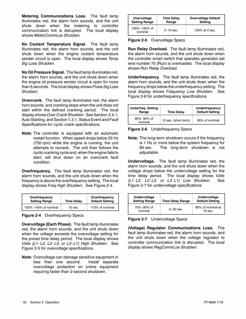
TP-6694 7/1942 Section 2 Operation
Metering Communications Loss. The fault lampilluminates red, the alarm horn sounds, and the unitshuts down when the metering to controllercommunication link is disrupted. The local displayshows MeterCommLos Shutdwn.
No Coolant Temperature Signal. The fault lampilluminates red, the alarm horn sounds, and the unitshuts down when the engine coolant temperaturesender circuit is open. The local display shows TempSig Loss Shutdwn.
NoOil PressureSignal. The fault lamp illuminates red,the alarm horn sounds, and the unit shuts down whenthe engine oil pressure sender circuit is open for morethan 5 seconds. The local display showsPressSig LossShutdwn.
Overcrank. The fault lamp illuminates red, the alarmhorn sounds, and cranking stops when the unit does notstart within the defined cranking period. The localdisplay showsOverCrankShutdwn. SeeSection 2.4.1,Auto Starting, and Section 1.3.1, Status Event and FaultSpecifications for cyclic crank specifications.
Note: The controller is equipped with an automaticrestart function. When speed drops below 25 Hz(750 rpm) while the engine is running, the unitattempts to recrank. The unit then follows thecyclic cranking cycle and,when the engine fails tostart, will shut down on an overcrank faultcondition.
Overfrequency. The fault lamp illuminates red, thealarm horn sounds, and the unit shuts down when thefrequency is above the overfrequency setting. The localdisplay shows Freq High Shutdwn. See Figure 2-4.
OverfrequencySetting Range Time Delay
OverfrequencyDefault Setting
102%- 140% of nominal 10 sec. 110% of nominal
Figure 2-4 Overfrequency Specs
Overvoltage (Each Phase). The fault lamp illuminatesred, the alarm horn sounds, and the unit shuts downwhen the voltage exceeds the overvoltage setting forthe preset time delay period. The local display showsVolts (L1- L2, L2- L3, or L3- L1) High Shutdwn. SeeFigure 2-5 for overvoltage specifications.
Note: Overvoltage can damage sensitive equipment inless than one second. Install separateovervoltage protection on online equipmentrequiring faster than 2-second shutdown.
OvervoltageSetting Range
Time DelayRange
Overvoltage DefaultSetting
105%- 135% ofnominal 2- 10 sec. 120% at 2 sec.
Figure 2-5 Overvoltage Specs
Run Relay Overload. The fault lamp illuminates red,the alarm horn sounds, and the unit shuts down whenthe controller smart switch that operates generator setwire number 70 (Run) is overloaded. The local displayshows Run Relay Overload.
Underfrequency. The fault lamp illuminates red, thealarm horn sounds, and the unit shuts down when thefrequency drops below the underfrequency setting. Thelocal display shows Frequency Low Shutdwn. SeeFigure 2-6 for underfrequency specifications.
Underfreq. SettingRange Time Delay
UnderfrequencyDefault Setting
80%- 95% ofnominal 10 sec. (short term) 90% of nominal
Figure 2-6 Underfrequency Specs
Note: The long-term shutdown occurs if the frequencyis 1 Hz or more below the system frequency for60 sec. The long-term shutdown is notadjustable.
Undervoltage. The fault lamp illuminates red, thealarm horn sounds, and the unit shuts down when thevoltage drops below the undervoltage setting for thetime delay period. The local display shows Volts(L1- L2, L2- L3, or L3- L1) Low Shutdwn. SeeFigure 2-7 for undervoltage specifications
UndervoltageSetting Range Time Delay Range
UndervoltageDefault Setting
70%- 95% ofnominal 5- 30 sec.
80% of nominal at10 sec.
Figure 2-7 Undervoltage Specs
(Voltage) Regulator Communications Loss. Thefault lamp illuminates red, the alarm horn sounds, andthe unit shuts down when the voltage regulator tocontroller communication link is disrupted. The localdisplay shows RegCommLos Shutdwn.
TP-6694 7/19 43Section 2 Operation
2.4.7 Status and Notice Digital Displays
Warnings and shutdown faults appear on the digitaldisplay and become part of the event history. Beyondthe warnings and shutdowns there are several eventswhich also appear on the digital display. Status is anevent that is not an alert but is part of the event history.Notice is an alert that is not part of the event history.
The controller allows a selected number of changes bythe user for setting up the controller application whichare covered in this section.
Note: Text shown in italics in this section of the manualrepresents digital display messages.
AlarmSilence. This statusmessage indicates whetherthe alarm horn can be silenced in any button mode(OFF/RESET- AUTO-RUN) or requires the AUTObutton be pressed first compliant per NFPA 110. UseSiteTecht software to change this setting. See Section2.4.8,ControllerResetting procedure, for information onresetting the system.
The local display shows AlrmSilence: Always when thealarm horn can be silenced with the master controlbuttons in any position (default setting).
The local display shows AlrmSilence: Auto Only whenthe alarm horn can be silenced only when in the AUTOmode.
Backup Parameters Loaded. This status messageindicates that backup parameter firmware is now loadedon the controller using SiteTecht software. The localdisplay shows Backup Pars Status.
Chicago Code Active. This notice message indicatesthat a pass code is required to access the controller.Use SiteTecht software to set up the feature. The localdisplay shows Auto Locked Notice.
Emergency Power System (EPS) Supplying Load.This notice message indicates when the generator setsupplies more than 1% of the rated standby outputcurrent. The local display shows Emerg Pwr OnNotice.
Engine Cooldown (Delay) Active. This noticemessage indicates that the delay for engine cooldown isactive where the generator set will continue to run afterthe OFF/RESET button is pressed. The unit willcontinue to run until the time delay times out. The localdisplay shows Eng Cooldown Notice.
Engine Start Aid Active. This notice messageindicates that the start aid is active and will energize anengine equipped preheat or ether system during thecrank cycle. Use SiteTecht software to set up thisfeature. The local display shows Starting Aid Notice.
Engine Start Delay Active. This notice messageindicates that the delay for engine start is active wherethe generator set will not start right after the RUN buttonis pressed. The unit will start cranking after the timedelay times out. The local display shows Start DelayNotice.
Engine Started. This status indicates that thegenerator set start circuit is closedallowing theengine tocrank and run. The local display shows Engine StartStatus.
Engine Stopped. This status indicates that thegenerator set start circuit is open causing the engine toshut down. The local display showsEngineStopStatus.
Generator Running. This notice indicates that thegenerator set has started and is running. The localdisplay shows Gen Running Notice.
TP-6694 7/1944 Section 2 Operation
Generator Set Calibration (User Defined). Thisselectable display is in the GenSet Calibration Menuallowing the user to calibrate the controller andgenerator set. Use thePushbutton/Rotary Selector Dialto navigate and select this feature.
Changes to this displaymust be donewith the generatorset running. The local display shows Enter calib? No orYes. Select No to make no change. Select Yes tocalibrate the following values:
D Volts L1- L2: x.x V
D Volts L2- L3: x.x V
D Volts L3- L1: x.x VD Volts L1- N: x.x V
D Volts L2- N: x.x VD Volts L3- N: x.x V
D Current L1: x.x A
D Current L2: x.x A
D Current L3: x.x A
The user can individually calibrate the values above orreset all of them. The local displayReset all calib? No orYes. Select No to make no changes and exit GenSetCalibration. Select Yes to reset all of the values.
When calibrating voltage, the metered value and thenumber being entered as the calibrated value must bewithin 10% of the system operating voltage.
When calibrating current, the metered value must be atleast 25% of the rated current on units smaller than100 kW and at least 50 amps on units rated larger than100 kW. The number being entered as the calibratedvalue must be within 10% of the metered value.
Measurement Units (User Defined). This selectabledisplay is in the GenSet SystemMenu allowing the userto choose betweenMetric andEnglish displays. Use thePushbutton/Rotary Selector Dial to navigate and selectthis feature. Changes to this display can be done withthe generator set running or stopped. The local displayshows Meas Units: Metric or Meas Units: English.
NFPA 110 Alarm Active. This notice messageindicates that the alarm for NFPA110 is active. The faultlamp illuminates yellow (warning) or red (shutdown), thealarm horn sounds, and the units shuts down (if ashutdown fault is detected) when the NFPA 110 faultsignals the controller. The local display shows therespective fault message. TheNFPA110 faults include:
D Battery charger faultD EPS supplying loadD High battery voltageD High coolant temperature shutdownD High coolant temperature warningD High engine speedD Low battery voltageD Low coolant levelD Low coolant temperature warningD Low fuel (level or pressure)D Low oil pressure shutdownD Low oil pressure warningD Master switch not in autoD Overcrank
Remote Start. This status indicates that the generatorset start circuit was closed from a remote locationallowing the engine to crank and run. The remotelocation is typically a set of contacts on a transfer switchor remote start switch. The local display showsRemoteStart Status.
SystemReady. This status indicates that the generatorset is in the AUTOmode and available to start if the startcircuit is closed. The local display shows SystemReady.
System Timer Failed. This notice indicates that thecontroller timer logic has failed to time out a designatedfunction. The local display shows Timer Error Notice.
Voltage Regulator Adjustment (User Defined). Thisfeature is in the Voltage Regulator Menu allowing theuser to fine adjust the output voltage. Use thePushbutton/Rotary Selector Dial to navigate and selectthis feature. Changes to this display must be done withthe generator set running. The local display showsEnter volt reg? No or Yes. Select No to exit the voltageregulator menu. Select Yes to change the local displayVR Volt Adj: xxx.x V.
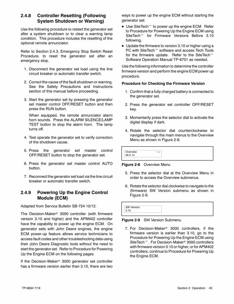
TP-6694 7/19 45Section 2 Operation
2.4.8 Controller Resetting (FollowingSystem Shutdown or Warning)
Use the following procedure to restart the generator setafter a system shutdown or to clear a warning lampcondition. This procedure includes the resetting of theoptional remote annunciator.
Refer to Section 2.4.3, Emergency Stop Switch ResetProcedure, to reset the generator set after anemergency stop.
1. Disconnect the generator set load using the linecircuit breaker or automatic transfer switch.
2. Correct the cause of the fault shutdown or warning.See the Safety Precautions and Instructionssection of this manual before proceeding.
3. Start the generator set by pressing the generatorset master control OFF/RESET button and thenpress the RUN button.
When equipped, the remote annunciator alarmhorn sounds. Press the ALARM SILENCE/LAMPTEST button to stop the alarm horn. The lampturns off.
4. Test operate the generator set to verify correctionof the shutdown cause.
5. Press the generator set master controlOFF/RESET button to stop the generator set.
6. Press the generator set master control AUTObutton.
7. Reconnect the generator set load via the line circuitbreaker or automatic transfer switch.
2.4.9 Powering Up the Engine ControlModule (ECM)
Adapted from Service Bulletin SB-724 10/12.
The Decision-Makerr 3000 controller (with firmwareversion 3.10 and higher) and the APM402 controllerhave the capability to power up the engine ECM. Ongenerator sets with John Deere engines, the engineECM power-up feature allows service technicians toaccess fault codes and other troubleshooting data usingtheir John Deere Diagnostic tools without the need tostart the generator set. Refer to Procedure for PoweringUp the Engine ECM on the following pages.
If the Decision-Makerr 3000 generator set controllerhas a firmware version earlier than 3.10, there are two
ways to power up the engine ECM without starting thegenerator set:
D Use SiteTecht to power up the engine ECM. Referto Procedure for Powering Up the Engine ECM usingSiteTecht for Firmware Versions Before 3.10following.
D Update the firmware to version 3.10 or higher using aPC with SiteTecht software and access Tech Toolsfor the firmware update. Refer to the SiteTechtSoftware Operation Manual TP-6701 as needed.
Use the following information to determine the controllerfirmware version and perform the engine ECMpower upprocedure.
Procedure for Checking the Firmware Version
1. Confirm that a fully charged battery is connected tothe generator set.
2. Press the generator set controller OFF/RESETkey.
3. Momentarily press the selector dial to activate thedigital display if dark.
4. Rotate the selector dial counterclockwise tonavigate through the main menus to the OverviewMenu as shown in Figure 2-8.
Overview - - >##.# hr
Figure 2-8 Overview Menu
5. Press the selector dial at the Overview Menu inorder to access the Overview submenus.
6. Rotate the selector dial clockwise to navigate to the(firmware) SW Version submenu as shown inFigure 2-9.
SW Version:3.10
Figure 2-9 SW Version Submenu
7. For Decision-Makerr 3000 controllers, if thefirmware version is earlier than 3.10, go to theProcedure for Powering Up the Engine ECM usingSiteTecht. For Decision-Makerr 3000 controllerswith firmware version 3.10or higher, or for APM402controllers, continue to Procedure for Powering Upthe Engine ECM.
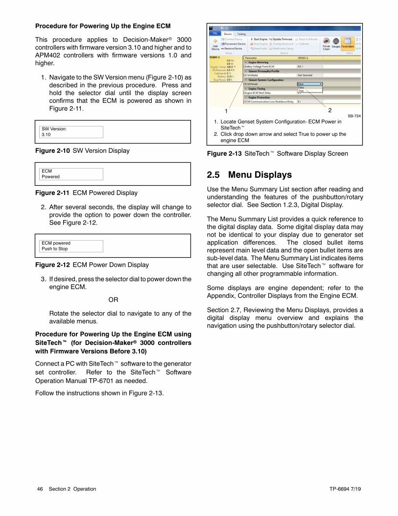
TP-6694 7/1946 Section 2 Operation
Procedure for Powering Up the Engine ECM
This procedure applies to Decision-Makerr 3000controllers with firmware version 3.10 and higher and toAPM402 controllers with firmware versions 1.0 andhigher.
1. Navigate to the SWVersion menu (Figure 2-10) asdescribed in the previous procedure. Press andhold the selector dial until the display screenconfirms that the ECM is powered as shown inFigure 2-11.
SW Version:3.10
Figure 2-10 SW Version Display
ECMPowered
Figure 2-11 ECM Powered Display
2. After several seconds, the display will change toprovide the option to power down the controller.See Figure 2-12.
ECM poweredPush to Stop
Figure 2-12 ECM Power Down Display
3. If desired, press the selector dial to power down theengine ECM.
OR
Rotate the selector dial to navigate to any of theavailable menus.
Procedure for Powering Up the Engine ECM usingSiteTecht (for Decision-Makerr 3000 controllerswith Firmware Versions Before 3.10)
Connect a PCwith SiteTecht software to the generatorset controller. Refer to the SiteTecht SoftwareOperation Manual TP-6701 as needed.
Follow the instructions shown in Figure 2-13.
1. Locate Genset System Configuration- ECM Power inSiteTecht
2. Click drop down arrow and select True to power up theengine ECM
SB-7241 2
Figure 2-13 SiteTecht Software Display Screen
2.5 Menu Displays
Use the Menu Summary List section after reading andunderstanding the features of the pushbutton/rotaryselector dial. See Section 1.2.3, Digital Display.
The Menu Summary List provides a quick reference tothe digital display data. Some digital display data maynot be identical to your display due to generator setapplication differences. The closed bullet itemsrepresent main level data and the open bullet items aresub-level data. TheMenuSummary List indicates itemsthat are user selectable. Use SiteTecht software forchanging all other programmable information.
Some displays are engine dependent; refer to theAppendix, Controller Displays from the Engine ECM.
Section 2.7, Reviewing the Menu Displays, provides adigital display menu overview and explains thenavigation using the pushbutton/rotary selector dial.
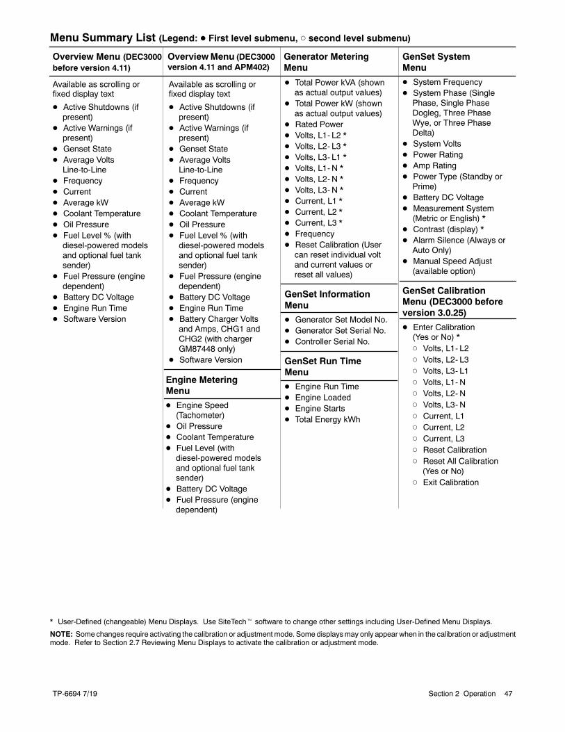
TP-6694 7/19 47Section 2 Operation
Menu Summary List (Legend: D First level submenu, d second level submenu)
GenSet SystemMenu
D System FrequencyD System Phase (SinglePhase, Single PhaseDogleg, Three PhaseWye, or Three PhaseDelta)
D System VoltsD Power RatingD Amp RatingD Power Type (Standby orPrime)
D Battery DC VoltageD Measurement System(Metric or English) *
D Contrast (display) *D Alarm Silence (Always orAuto Only)
D Manual Speed Adjust(available option)
GenSet CalibrationMenu (DEC3000 beforeversion 3.0.25)
D Enter Calibration(Yes or No) *d Volts, L1- L2d Volts, L2- L3d Volts, L3- L1d Volts, L1- Nd Volts, L2- Nd Volts, L3- Nd Current, L1d Current, L2d Current, L3d Reset Calibrationd Reset All Calibration(Yes or No)
d Exit Calibration
D Total Power kVA (shownas actual output values)
D Total Power kW (shownas actual output values)
D Rated PowerD Volts, L1- L2 *D Volts, L2- L3 *D Volts, L3- L1 *D Volts, L1- N *D Volts, L2- N *D Volts, L3- N *D Current, L1 *D Current, L2 *D Current, L3 *D FrequencyD Reset Calibration (Usercan reset individual voltand current values orreset all values)
GenSet InformationMenu
D Generator Set Model No.D Generator Set Serial No.D Controller Serial No.
GenSet Run TimeMenu
D Engine Run TimeD Engine LoadedD Engine StartsD Total Energy kWh
Overview Menu (DEC3000before version 4.11)
OverviewMenu (DEC3000version 4.11 and APM402)
Available as scrolling orfixed display text
D Active Shutdowns (ifpresent)
D Active Warnings (ifpresent)
D Genset StateD Average VoltsLine-to-Line
D FrequencyD CurrentD Average kWD Coolant TemperatureD Oil PressureD Fuel Level % (withdiesel-powered modelsand optional fuel tanksender)
D Fuel Pressure (enginedependent)
D Battery DC VoltageD Engine Run TimeD Software Version
Engine MeteringMenu
D Engine Speed(Tachometer)
D Oil PressureD Coolant TemperatureD Fuel Level (withdiesel-powered modelsand optional fuel tanksender)
D Battery DC VoltageD Fuel Pressure (enginedependent)
Generator MeteringMenu
Available as scrolling orfixed display text
D Active Shutdowns (ifpresent)
D Active Warnings (ifpresent)
D Genset StateD Average Volts
Line-to-LineD FrequencyD CurrentD Average kWD Coolant TemperatureD Oil PressureD Fuel Level % (with
diesel-powered modelsand optional fuel tanksender)
D Fuel Pressure (enginedependent)
D Battery DC VoltageD Engine Run TimeD Battery Charger Volts
and Amps, CHG1 andCHG2 (with chargerGM87448 only)
D Software Version
* User-Defined (changeable) Menu Displays. Use SiteTecht software to change other settings including User-Defined Menu Displays.
NOTE: Some changes require activating the calibration or adjustment mode. Some displaysmay only appear when in the calibration or adjustmentmode. Refer to Section 2.7 Reviewing Menu Displays to activate the calibration or adjustment mode.
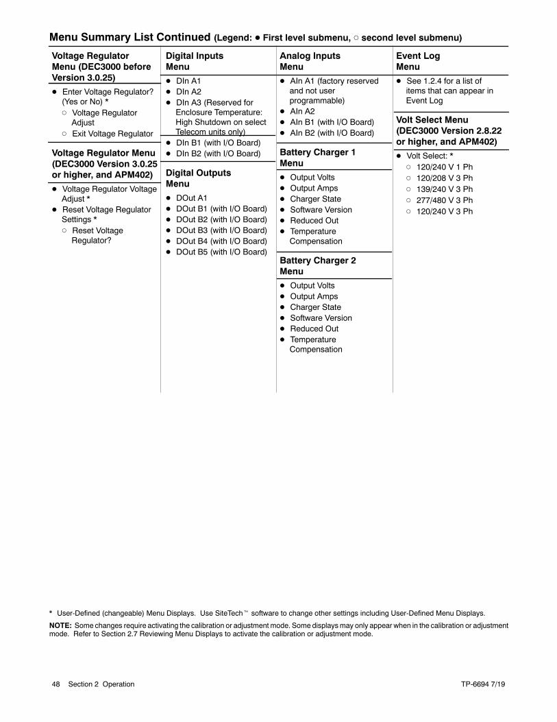
TP-6694 7/1948 Section 2 Operation
Menu Summary List Continued (Legend: D First level submenu, d second level submenu)
Event LogMenu
D See 1.2.4 for a list ofitems that can appear inEvent Log
Volt Select Menu(DEC3000 Version 2.8.22or higher, and APM402)
D Volt Select: *d 120/240 V 1 Phd 120/208 V 3 Phd 139/240 V 3 Phd 277/480 V 3 Phd 120/240 V 3 Ph
Analog InputsMenu
D AIn A1 (factory reservedand not userprogrammable)
D AIn A2D AIn B1 (with I/O Board)D AIn B2 (with I/O Board)
Battery Charger 1Menu
D Output VoltsD Output AmpsD Charger StateD Software VersionD Reduced OutD TemperatureCompensation
Battery Charger 2Menu
D Output VoltsD Output AmpsD Charger StateD Software VersionD Reduced OutD TemperatureCompensation
Digital InputsMenu
D DIn A1D DIn A2D DIn A3 (Reserved for
Enclosure Temperature:High Shutdown on selectTelecom units only)
D DIn B1 (with I/O Board)D DIn B2 (with I/O Board)
Digital OutputsMenu
D DOut A1D DOut B1 (with I/O Board)D DOut B2 (with I/O Board)D DOut B3 (with I/O Board)D DOut B4 (with I/O Board)D DOut B5 (with I/O Board)
Voltage RegulatorMenu (DEC3000 beforeVersion 3.0.25)
D Enter Voltage Regulator?(Yes or No) *d Voltage RegulatorAdjust
d Exit Voltage Regulator
Voltage Regulator Menu(DEC3000 Version 3.0.25or higher, and APM402)
D Voltage Regulator VoltageAdjust *
D Reset Voltage RegulatorSettings *d Reset VoltageRegulator?
* User-Defined (changeable) Menu Displays. Use SiteTecht software to change other settings including User-Defined Menu Displays.
NOTE: Some changes require activating the calibration or adjustment mode. Some displaysmay only appear when in the calibration or adjustmentmode. Refer to Section 2.7 Reviewing Menu Displays to activate the calibration or adjustment mode.
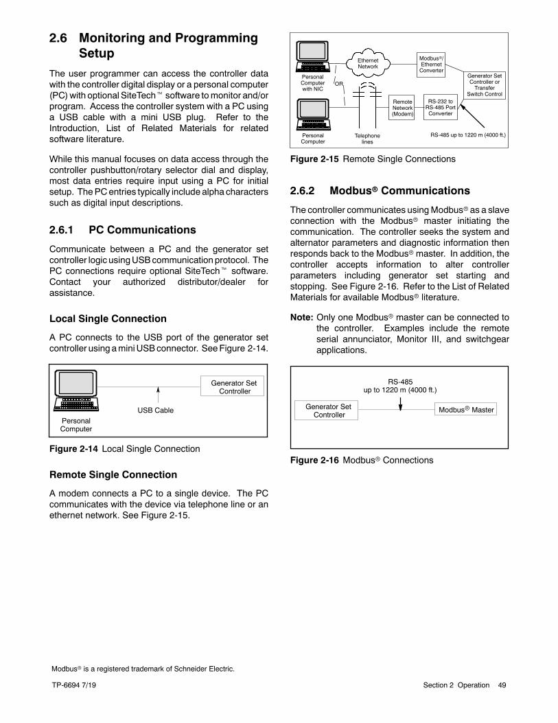
TP-6694 7/19 49Section 2 Operation
2.6 Monitoring and ProgrammingSetup
The user programmer can access the controller datawith the controller digital display or a personal computer(PC)with optional SiteTecht software tomonitor and/orprogram. Access the controller system with a PC usinga USB cable with a mini USB plug. Refer to theIntroduction, List of Related Materials for relatedsoftware literature.
While this manual focuses on data access through thecontroller pushbutton/rotary selector dial and display,most data entries require input using a PC for initialsetup. ThePCentries typically include alpha characterssuch as digital input descriptions.
2.6.1 PC Communications
Communicate between a PC and the generator setcontroller logic usingUSBcommunication protocol. ThePC connections require optional SiteTecht software.Contact your authorized distributor/dealer forassistance.
Local Single Connection
A PC connects to the USB port of the generator setcontroller using aminiUSBconnector. SeeFigure 2-14.
PersonalComputer
Generator SetController
USB Cable
Figure 2-14 Local Single Connection
Remote Single Connection
A modem connects a PC to a single device. The PCcommunicates with the device via telephone line or anethernet network. See Figure 2-15.
PersonalComputerwith NIC
EthernetNetwork
RemoteNetwork(Modem)
RS-232 toRS-485 PortConverter
Modbusr/EthernetConverter
OR
Telephonelines
PersonalComputer
Generator SetController orTransfer
Switch Control
RS-485 up to 1220 m (4000 ft.)
Figure 2-15 Remote Single Connections
2.6.2 Modbusr Communications
The controller communicates usingModbusr as a slaveconnection with the Modbusr master initiating thecommunication. The controller seeks the system andalternator parameters and diagnostic information thenresponds back to the Modbusrmaster. In addition, thecontroller accepts information to alter controllerparameters including generator set starting andstopping. See Figure 2-16. Refer to the List of RelatedMaterials for available Modbusr literature.
Note: Only one Modbusr master can be connected tothe controller. Examples include the remoteserial annunciator, Monitor III, and switchgearapplications.
Generator SetController
Modbusr Master
RS-485up to 1220 m (4000 ft.)
Figure 2-16 Modbusr Connections
Modbusr is a registered trademark of Schneider Electric.
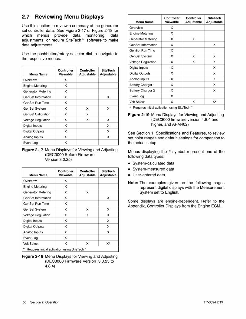
TP-6694 7/1950 Section 2 Operation
2.7 Reviewing Menu Displays
Use this section to review a summary of the generatorset controller data. See Figure 2-17 or Figure 2-18 forwhich menus provide data monitoring, dataadjustments, or require SiteTecht software to makedata adjustments.
Use the pushbutton/rotary selector dial to navigate tothe respective menus.
Menu NameControllerViewable
ControllerAdjustable
SiteTechAdjustable
Overview X
Engine Metering X
Generator Metering X
GenSet Information X X
GenSet Run Time X
GenSet System X X X
GenSet Calibration X X
Voltage Regulation X X X
Digital Inputs X X
Digital Outputs X X
Analog Inputs X X
Event Log X
Figure 2-17 Menu Displays for Viewing and Adjusting(DEC3000 Before FirmwareVersion 3.0.25)
Menu NameControllerViewable
ControllerAdjustable
SiteTechAdjustable
Overview X
Engine Metering X
Generator Metering X X
GenSet Information X X
GenSet Run Time X
GenSet System X X X
Voltage Regulation X X X
Digital Inputs X X
Digital Outputs X X
Analog Inputs X X
Event Log X
Volt Select X X X*
* Requires initial activation using SiteTecht
Figure 2-18 Menu Displays for Viewing and Adjusting(DEC3000 Firmware Version 3.0.25 to4.8.4)
Menu NameControllerViewable
ControllerAdjustable
SiteTechAdjustable
Overview X
Engine Metering X
Generator Metering X X
GenSet Information X X
GenSet Run Time X
GenSet System X X X
Voltage Regulation X X X
Digital Inputs X X
Digital Outputs X X
Analog Inputs X X
Battery Charger 1 X X
Battery Charger 2 X X
Event Log X
Volt Select X X X*
* Requires initial activation using SiteTecht
Figure 2-19 Menu Displays for Viewing and Adjusting(DEC3000 firmware version 4.8.4 andhigher, and APM402)
See Section 1, Specifications and Features, to reviewset point ranges and default settings for comparison tothe actual setup.
Menus displaying the # symbol represent one of thefollowing data types:
D System-calculated data
D System-measured data
D User-entered data
Note: The examples given on the following pagesrepresent digital displays with the MeasurementSystem set to English.
Some displays are engine-dependent. Refer to theAppendix, Controller Displays from the Engine ECM.
TP-6694 7/19 51Section 2 Operation
2.7.1 Error Messages
Certain entries or attempted entries may cause thecontroller to display an error message. Some of theerror messages shown here are also shown as part of2.4.5 System Fault Warning Lamp with Digital Displaysand 2.4.6 System Fault Shutdown Lamp with DigitalDisplays.
CannotCalibrate appearswhenattempting to calibratethe voltage and current values in theGenSet Calibrationmenu with the unit stopped. The unit must be running inorder to make adjustments.
Cannot Edit When Stopped appears in the VoltageRegulatormenu when attempting to change theVRVoltAdj value when the unit is not running.
Default Parameters Loaded. The fault lampilluminates yellow and the alarm horn sounds when thecontroller detects that the default parameter settingswere loaded using SiteTecht software. The localdisplay shows Default Pars Warning.
ECMAddress Conflict. The fault lamp illuminates red,the alarm horn sounds, and the unit shuts down whenthe controller detects an error with the ECM address.The local display shows ECMAddr Err Shutdwn.
ECMModel Mismatch. The fault lamp illuminates red,the alarm horn sounds, and the unit shuts down whenthe controller detects an error with the ECMmodel. Thelocal display shows ECM Mismatch Shutdwn.
File System Error. The fault lamp illuminates red, thealarm horn sounds, and the unit shuts down when theinternal controller diagnostics detect a firmware fileerror. The local display shows File Error Shutdwn.
Max Alternator Current Low. The current value listedin the maximum alternator current personalityparameter is too low compared to the kW setting withinthe personality.
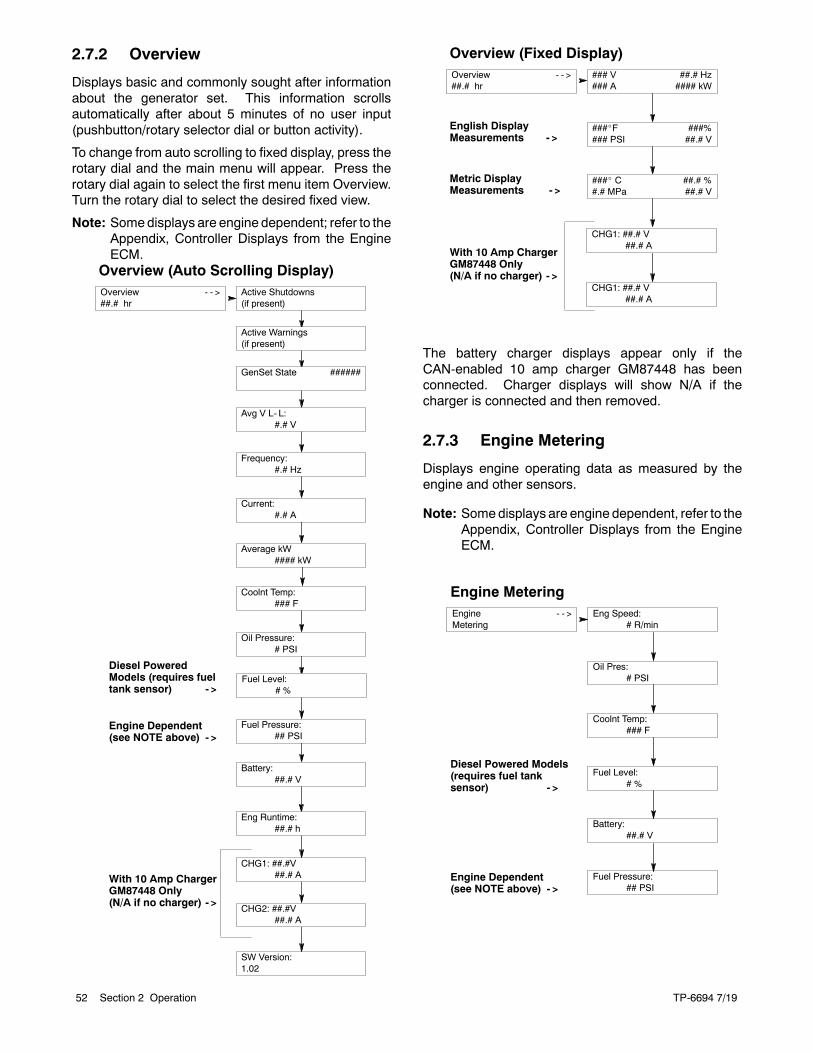
TP-6694 7/1952 Section 2 Operation
2.7.2 Overview
Displays basic and commonly sought after informationabout the generator set. This information scrollsautomatically after about 5 minutes of no user input(pushbutton/rotary selector dial or button activity).
To change from auto scrolling to fixed display, press therotary dial and the main menu will appear. Press therotary dial again to select the first menu item Overview.Turn the rotary dial to select the desired fixed view.
Note: Somedisplays are engine dependent; refer to theAppendix, Controller Displays from the EngineECM.
Overview (Auto Scrolling Display)Overview - - >##.# hr
Average kW#### kW
SW Version:1.02
Coolnt Temp:### F
Diesel PoweredModels (requires fueltank sensor) - >
Engine Dependent(see NOTE above) - >
Active Shutdowns(if present)
Active Warnings(if present)
GenSet State ######
Avg V L- L:#.# V
Frequency:#.# Hz
Current:#.# A
Oil Pressure:# PSI
Fuel Level:# %
Fuel Pressure:## PSI
Battery:##.# V
Eng Runtime:##.# h
CHG1: ##.#V##.# A
CHG2: ##.#V##.# A
With 10 Amp ChargerGM87448 Only(N/A if no charger) - >
Overview (Fixed Display)Overview - - >##.# hr
###_ C ##.# %#.# MPa ##.# V
### V ##.# Hz### A #### kW
###_F ###%### PSI ##.# V
English DisplayMeasurements - >
Metric DisplayMeasurements - >
CHG1: ##.# V##.# A
CHG1: ##.# V##.# A
With 10 Amp ChargerGM87448 Only(N/A if no charger) - >
The battery charger displays appear only if theCAN-enabled 10 amp charger GM87448 has beenconnected. Charger displays will show N/A if thecharger is connected and then removed.
2.7.3 Engine Metering
Displays engine operating data as measured by theengine and other sensors.
Note: Somedisplays are engine dependent, refer to theAppendix, Controller Displays from the EngineECM.
Engine MeteringEngine - - >Metering
Coolnt Temp:### F
Eng Speed:# R/min
Oil Pres:# PSI
Fuel Pressure:## PSI
Fuel Level:# %
Battery:##.# V
Diesel Powered Models(requires fuel tanksensor) - >
Engine Dependent(see NOTE above) - >
TP-6694 7/19 53Section 2 Operation
2.7.4 Generator Metering (andCalibration)
Displays generator output data including line-to-line andline-to-neutral voltages, current, frequency, totalkilowatts, and total kVA. The menu displaysthree-phase voltage and current readings whenapplicable.
All menu displays apply to both single-phase or three-phase voltages on the menu overview. The phasedesignation does not appear in the controller menudisplays. Some displays will show 0 values whensingle-phase connections are shown.
Note: For Decision-Makerr 3000 controllers withfirmware versions before 3.0.25, see Section2.7.8 for generator calibration.
Display also provides access to the calibration factorsfor metering (volts and amps). Changing the systemvoltage or replacing the main logic control circuit boardrequires calibration adjustment. Connect ameter with aminimum accuracy of 1% to the generator set outputleads to calibrate the voltage-sensing logic.
To enable calibration, start the generator set and selectthe Volts L1-L2 display. Then push and hold thepushbutton/rotary selector dial until the CalibrationEnabled popup appears. Calibration of each display isnow available. The display will show the following
values for three-phase generator sets. Single-phasegenerator sets will only display items marked (*).
D Volts L1-L2 *
D Volts L2-L3
D Volts L3-L1
D Volts L1-N *D Volts L2-N *
D Volts L3-ND Current L1 *
D Current L2 *
D Current L3
The user can change individual values or can selectReset Calib?-Yes to reset all voltage and currentvalues. The Reset Calib? display will only show ifcalibration is enabled.
When calibrating voltage, the metered value and thenumber being entered as the calibrated value must bewithin 10% of the system operating voltage.
When calibrating current, the metered value must be atleast 25% of the rated current on units smaller than100 kW and at least 50 amps on units rated larger than100 kW. The number being entered as the calibratedvalue must within 10% of the metered value.
To disable calibration, Rotate the pushbutton/rotaryselector dial until the <-Return popup appears.
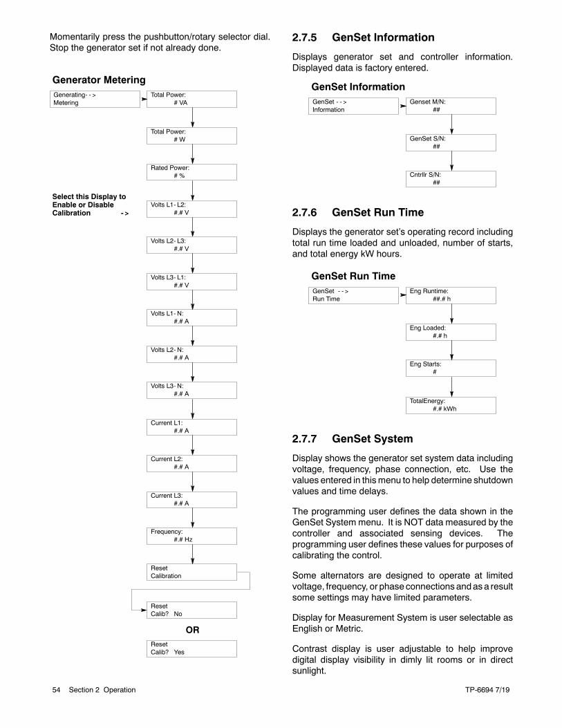
TP-6694 7/1954 Section 2 Operation
Momentarily press the pushbutton/rotary selector dial.Stop the generator set if not already done.
Generator MeteringGenerating- - >Metering
Rated Power:# %
Total Power:# VA
Total Power:# W
Volts L2- L3:#.# V
Volts L1- L2:#.# V
Volts L1- N:#.# A
Volts L3- L1:#.# V
Volts L3- N:#.# A
Volts L2- N:#.# A
Current L2:#.# A
Current L1:#.# A
Frequency:#.# Hz
Current L3:#.# A
Select this Display toEnable or DisableCalibration - >
ResetCalibration
ResetCalib? No
ResetCalib? Yes
OR
2.7.5 GenSet Information
Displays generator set and controller information.Displayed data is factory entered.
GenSet InformationGenSet - - >Information
Cntrllr S/N:##
Genset M/N:##
GenSet S/N:##
2.7.6 GenSet Run Time
Displays the generator set’s operating record includingtotal run time loaded and unloaded, number of starts,and total energy kW hours.
GenSet Run TimeGenSet - - >Run Time
Eng Starts:#
Eng Runtime:##.# h
Eng Loaded:#.# h
TotalEnergy:#.# kWh
2.7.7 GenSet System
Display shows the generator set system data includingvoltage, frequency, phase connection, etc. Use thevalues entered in thismenu to help determine shutdownvalues and time delays.
The programming user defines the data shown in theGenSet System menu. It is NOT data measured by thecontroller and associated sensing devices. Theprogramming user defines these values for purposes ofcalibrating the control.
Some alternators are designed to operate at limitedvoltage, frequency, or phaseconnections andasa resultsome settings may have limited parameters.
Display for Measurement System is user selectable asEnglish or Metric.
Contrast display is user adjustable to help improvedigital display visibility in dimly lit rooms or in directsunlight.
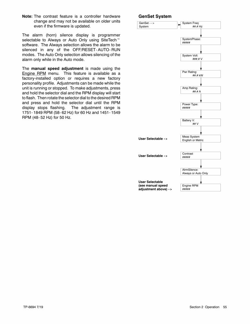
TP-6694 7/19 55Section 2 Operation
Note: The contrast feature is a controller hardwarechange and may not be available on older unitseven if the firmware is updated.
The alarm (horn) silence display is programmerselectable to Always or Auto Only using SiteTechtsoftware. The Always selection allows the alarm to besilenced in any of the OFF/RESET- AUTO-RUNmodes. The Auto Only selection allows silencing of thealarm only while in the Auto mode.
The manual speed adjustment is made using theEngine RPM menu. This feature is available as afactory-installed option or requires a new factorypersonality profile. Adjustments can be made while theunit is running or stopped. To make adjustments, pressand hold the selector dial and the RPM display will startto flash. Then rotate the selector dial to the desiredRPMand press and hold the selector dial until the RPMdisplay stops flashing. The adjustment range is1751- 1849 RPM (58- 62 Hz) for 60 Hz and 1451- 1549RPM (48- 52 Hz) for 50 Hz.
GenSet SystemGenSet - - >System
SystemPhase:#####
System Volt:###.# V
System Freq:##.# Hz
Amp Rating:##.# A
Pwr Rating:##.# kW
Battery V:## V
Power Type:#####
AlrmSilence:Always or Auto Only
User Selectable - >Meas SystemEnglish or Metric
Contrast#####User Selectable - >
Engine RPM#####
User Selectable(see manual speedadjustment above) - >
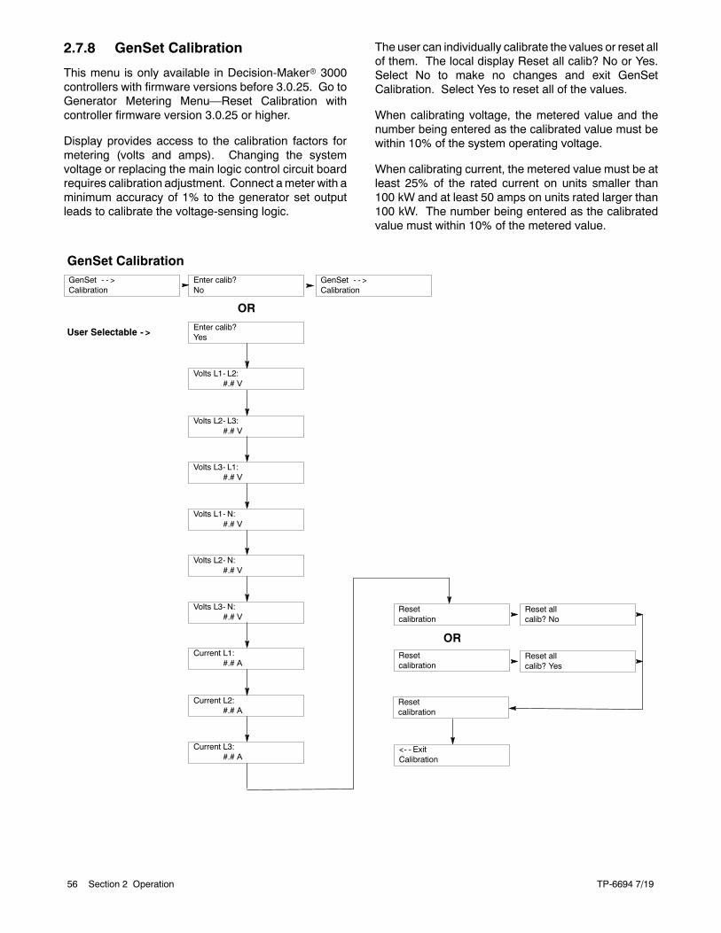
TP-6694 7/1956 Section 2 Operation
2.7.8 GenSet Calibration
This menu is only available in Decision-Makerr 3000controllers with firmware versions before 3.0.25. Go toGenerator Metering Menu—Reset Calibration withcontroller firmware version 3.0.25 or higher.
Display provides access to the calibration factors formetering (volts and amps). Changing the systemvoltage or replacing the main logic control circuit boardrequires calibration adjustment. Connect ameter with aminimum accuracy of 1% to the generator set outputleads to calibrate the voltage-sensing logic.
The user can individually calibrate the values or reset allof them. The local display Reset all calib? No or Yes.Select No to make no changes and exit GenSetCalibration. Select Yes to reset all of the values.
When calibrating voltage, the metered value and thenumber being entered as the calibrated value must bewithin 10% of the system operating voltage.
When calibrating current, the metered value must be atleast 25% of the rated current on units smaller than100 kW and at least 50 amps on units rated larger than100 kW. The number being entered as the calibratedvalue must within 10% of the metered value.
GenSet CalibrationGenSet - - >Calibration
Volts L1- L2:#.# V
Enter calib?No
Enter calib?Yes
Volts L3- L1:#.# V
Volts L2- L3:#.# V
Volts L2- N:#.# V
Volts L1- N:#.# V
Current L1:#.# A
Volts L3- N:#.# V
Current L3:#.# A
Current L2:#.# A
Resetcalibration
Resetcalibration
GenSet - - >Calibration
<- - ExitCalibration
Reset allcalib? No
Resetcalibration
Reset allcalib? Yes
OR
OR
User Selectable - >
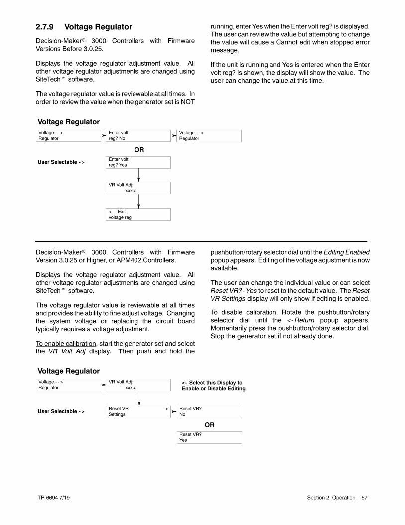
TP-6694 7/19 57Section 2 Operation
2.7.9 Voltage Regulator
Decision-Makerr 3000 Controllers with FirmwareVersions Before 3.0.25.
Displays the voltage regulator adjustment value. Allother voltage regulator adjustments are changed usingSiteTecht software.
The voltage regulator value is reviewable at all times. Inorder to review the value when the generator set is NOT
running, enter Yeswhen theEnter volt reg? is displayed.The user can review the value but attempting to changethe value will cause a Cannot edit when stopped errormessage.
If the unit is running and Yes is entered when the Entervolt reg? is shown, the display will show the value. Theuser can change the value at this time.
Voltage RegulatorVoltage - - >Regulator
VR Volt Adj:xxx.x
Enter voltreg? No
Enter voltreg? Yes
<- - Exitvoltage reg
Voltage - - >Regulator
OR
User Selectable - >
Decision-Makerr 3000 Controllers with FirmwareVersion 3.0.25 or Higher, or APM402 Controllers.
Displays the voltage regulator adjustment value. Allother voltage regulator adjustments are changed usingSiteTecht software.
The voltage regulator value is reviewable at all timesand provides the ability to fine adjust voltage. Changingthe system voltage or replacing the circuit boardtypically requires a voltage adjustment.
To enable calibration, start the generator set and selectthe VR Volt Adj display. Then push and hold the
pushbutton/rotary selector dial until the Editing Enabledpopupappears. Editing of the voltageadjustment is nowavailable.
The user can change the individual value or can selectReset VR?-Yes to reset to the default value. TheResetVR Settings display will only show if editing is enabled.
To disable calibration, Rotate the pushbutton/rotaryselector dial until the <-Return popup appears.Momentarily press the pushbutton/rotary selector dial.Stop the generator set if not already done.
Voltage RegulatorVoltage - - >Regulator
VR Volt Adj:xxx.x
Reset VR?No
Reset VR?Yes
Reset VR - >Settings
OR
User Selectable - >
<- Select this Display toEnable or Disable Editing
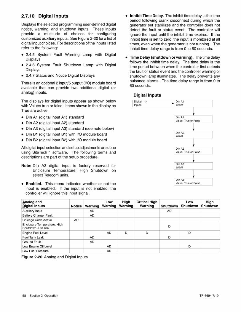
TP-6694 7/1958 Section 2 Operation
2.7.10 Digital Inputs
Displays the selected programming user-defined digitalnotice, warning, and shutdown inputs. These inputsprovide a multitude of choices for configuringcustomized auxiliary inputs. See Figure 2-20 for a list ofdigital input choices. For descriptions of the inputs listedrefer to the following:
D 2.4.5 System Fault Warning Lamp with DigitalDisplays
D 2.4.6 System Fault Shutdown Lamp with DigitalDisplays
D 2.4.7 Status and Notice Digital Displays
There is an optional 2 input/5 output (I/O) module boardavailable that can provide two additional digital (oranalog) inputs.
The displays for digital inputs appear as shown belowwith Values true or false. Items shown in the display asTrue are active.
D DIn A1 (digital input A1) standardD DIn A2 (digital input A2) standard
D DIn A3 (digital input A3) standard (see note below)
D DIn B1 (digital input B1) with I/O module board
D DIn B2 (digital input B2) with I/O module board
All digital input selection and setup adjustments are doneusing SiteTecht software. The following terms anddescriptions are part of the setup procedure.
Note: DIn A3 digital input is factory reserved forEnclosure Temperature: High Shutdown onselect Telecom units.
D Enabled. This menu indicates whether or not theinput is enabled. If the input is not enabled, thecontroller will ignore this input signal.
D Inhibit Time Delay. The inhibit time delay is the timeperiod following crank disconnect during which thegenerator set stabilizes and the controller does notdetect the fault or status event. The controller willignore the input until the inhibit time expires. If theinhibit time is set to zero, the input is monitored at alltimes, even when the generator is not running. Theinhibit time delay range is from 0 to 60 seconds.
D TimeDelay (shutdownorwarning). The time delayfollows the inhibit time delay. The time delay is thetime period between when the controller first detectsthe fault or status event and the controller warning orshutdown lamp illuminates. The delay prevents anynuisance alarms. The time delay range is from 0 to60 seconds.
Digital InputsDigital - - >Inputs
DIn A2#####
DIn A1#####
DIn A1Value: True or False
DIn A3#####
DIn A2Value: True or False
DIn A3Value: True or False
Analog andDigital Inputs Notice Warning
LowWarning
HighWarning
Critical HighWarning Shutdown
LowShutdown
HighShutdown
Auxiliary Input AD AD
Battery Charger Fault ADChicago Code Active ADEnclosure Temperature: HighShutdown (Din A3) D
Engine Fuel Level AD D D DFuel Tank Leak AD DGround Fault ADLow Engine Oil Level AD DLow Fuel Pressure AD
Figure 2-20 Analog and Digital Inputs
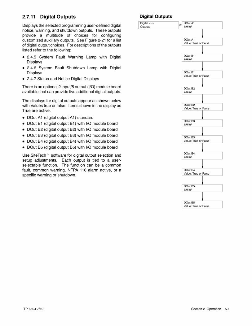
TP-6694 7/19 59Section 2 Operation
2.7.11 Digital Outputs
Displays the selected programming user-defined digitalnotice, warning, and shutdown outputs. These outputsprovide a multitude of choices for configuringcustomized auxiliary outputs. See Figure 2-21 for a listof digital output choices. For descriptions of the outputslisted refer to the following:
D 2.4.5 System Fault Warning Lamp with DigitalDisplays
D 2.4.6 System Fault Shutdown Lamp with DigitalDisplays
D 2.4.7 Status and Notice Digital Displays
There is an optional 2 input/5 output (I/O) module boardavailable that can provide five additional digital outputs.
The displays for digital outputs appear as shown belowwith Values true or false. Items shown in the display asTrue are active.
D DOut A1 (digital output A1) standard
D DOut B1 (digital output B1) with I/O module boardD DOut B2 (digital output B2) with I/O module board
D DOut B3 (digital output B3) with I/O module board
D DOut B4 (digital output B4) with I/O module board
D DOut B5 (digital output B5) with I/O module board
Use SiteTecht software for digital output selection andsetup adjustments. Each output is tied to a user-selectable function. The function can be a commonfault, common warning, NFPA 110 alarm active, or aspecific warning or shutdown.
Digital OutputsDigital - - >Outputs
DOut B1#####
DOut A1#####
DOut A1Value: True or False
DOut B2#####
DOut B1Value: True or False
DOut B3#####
DOut B2Value: True or False
DOut B4#####
DOut B3Value: True or False
DOut B5#####
DOut B4Value: True or False
DOut B5Value: True or False
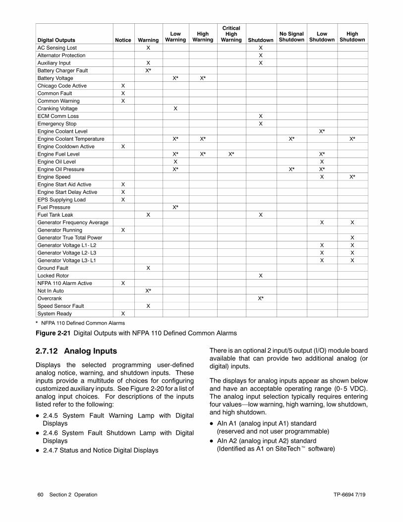
TP-6694 7/1960 Section 2 Operation
Digital Outputs Notice WarningLow
WarningHigh
Warning
CriticalHigh
Warning ShutdownNo SignalShutdown
LowShutdown
HighShutdown
AC Sensing Lost X XAlternator Protection XAuxiliary Input X XBattery Charger Fault X*
Battery Voltage X* X*Chicago Code Active XCommon Fault XCommon Warning XCranking Voltage X
ECM Comm Loss XEmergency Stop XEngine Coolant Level X*Engine Coolant Temperature X* X* X* X*Engine Cooldown Active X
Engine Fuel Level X* X* X* X*Engine Oil Level X XEngine Oil Pressure X* X* X*Engine Speed X X*Engine Start Aid Active X
Engine Start Delay Active XEPS Supplying Load XFuel Pressure X*Fuel Tank Leak X XGenerator Frequency Average X X
Generator Running XGenerator True Total Power XGenerator Voltage L1- L2 X XGenerator Voltage L2- L3 X XGenerator Voltage L3- L1 X X
Ground Fault XLocked Rotor XNFPA 110 Alarm Active XNot In Auto X*Overcrank X*
Speed Sensor Fault XSystem Ready X
* NFPA 110 Defined Common Alarms
Figure 2-21 Digital Outputs with NFPA 110 Defined Common Alarms
2.7.12 Analog Inputs
Displays the selected programming user-definedanalog notice, warning, and shutdown inputs. Theseinputs provide a multitude of choices for configuringcustomized auxiliary inputs. See Figure 2-20 for a list ofanalog input choices. For descriptions of the inputslisted refer to the following:
D 2.4.5 System Fault Warning Lamp with DigitalDisplays
D 2.4.6 System Fault Shutdown Lamp with DigitalDisplays
D 2.4.7 Status and Notice Digital Displays
There is an optional 2 input/5 output (I/O) module boardavailable that can provide two additional analog (ordigital) inputs.
The displays for analog inputs appear as shown belowand have an acceptable operating range (0- 5 VDC).The analog input selection typically requires enteringfour values—low warning, high warning, low shutdown,and high shutdown.
D AIn A1 (analog input A1) standard(reserved and not user programmable)
D AIn A2 (analog input A2) standard(Identified as A1 on SiteTecht software)
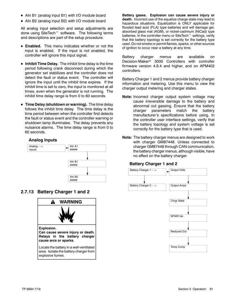
TP-6694 7/19 61Section 2 Operation
D AIn B1 (analog input B1) with I/O module board
D AIn B2 (analog input B2) with I/O module board
All analog input selection and setup adjustments aredone using SiteTecht software. The following termsand descriptions are part of the setup procedure.
D Enabled. This menu indicates whether or not theinput is enabled. If the input is not enabled, thecontroller will ignore this input signal.
D Inhibit Time Delay. The inhibit time delay is the timeperiod following crank disconnect during which thegenerator set stabilizes and the controller does notdetect the fault or status event. The controller willignore the input until the inhibit time expires. If theinhibit time is set to zero, the input is monitored at alltimes, even when the generator is not running. Theinhibit time delay range is from 0 to 60 seconds.
D TimeDelay (shutdownorwarning). The time delayfollows the inhibit time delay. The time delay is thetime period between when the controller first detectsthe fault or status event and the controller warning orshutdown lamp illuminates. The delay prevents anynuisance alarms. The time delay range is from 0 to60 seconds.
Analog InputsAnalog - - >Inputs
AIn B2#####
AIn A1#####
AIn B1#####
2.7.13 Battery Charger 1 and 2
Explosion.Can cause severe injury or death.Relays in the battery chargercause arcs or sparks.
Locate the battery in a well-ventilatedarea. Isolate the battery charger fromexplosive fumes.
WARNING
Battery gases. Explosion can cause severe injury ordeath. Incorrect use of the equalize charge state may lead tohazardous situations. Equalization is ONLY applicable forflooded lead acid (FLA) type batteries and will damage gel,absorbed glass mat (AGM), or nickel-cadmium (NiCad) typebatteries. In the controller menu or SiteTecht settings, verifythat the battery topology is set correctly for the battery typeused. Do not smoke or permit flames, sparks, or other sourcesof ignition to occur near a battery at any time.
Battery charger menus are available onDecision-Makerr 3000 Controllers with controllerfirmware version 4.8.4 and higher, and on APM402controllers.
Battery Charger 1 and 2 menus provide battery chargerinformation and metering. Use this menu to view thecharger output metering and charger states.
Note: Incorrect charger output system voltage maycause irreversible damage to the battery andabnormal out gassing. Ensure that the batterycharger parameters match the batterymanufacturer’s specifications before using. Inthe controller user interface settings, verify thatthe battery topology and system voltage is setcorrectly for the battery type that is used.
Note: The battery charger menus are designed to workwith charger GM87448. Unless connected tocharger GM87448 through CAN communication,the battery chargermenus, although visible, haveno effect on the battery charger.
Battery Charger 1 and 2Battery Charger 1 - - > Output Volts
Output Amps
Chrgr State
SFWR Ver
Reduced Out
Temp Comp
Battery Charger 2 - - >
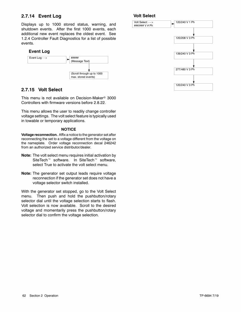
TP-6694 7/1962 Section 2 Operation
2.7.14 Event Log
Displays up to 1000 stored status, warning, andshutdown events. After the first 1000 events, eachadditional new event replaces the oldest event. See1.2.4 Controller Fault Diagnostics for a list of possibleevents.
Event LogEvent Log - - > #####
(Message Text)
(Scroll through up to 1000max. stored events)
2.7.15 Volt Select
This menu is not available on Decision-Makerr 3000Controllers with firmware versions before 2.8.22.
This menu allows the user to readily change controllervoltage settings. The volt select feature is typically usedin towable or temporary applications.
NOTICEVoltage reconnection. Affix a notice to thegenerator set afterreconnecting the set to a voltage different from the voltage onthe nameplate. Order voltage reconnection decal 246242from an authorized service distributor/dealer.
Note: The volt select menu requires initial activation bySiteTecht software. In SiteTecht software,select True to activate the volt select menu.
Note: The generator set output leads require voltagereconnection if the generator set does not have avoltage selector switch installed.
With the generator set stopped, go to the Volt Selectmenu. Then push and hold the pushbutton/rotaryselector dial until the voltage selection starts to flash.Volt selection is now available. Scroll to the desiredvoltage and momentarily press the pushbutton/rotaryselector dial to confirm the voltage selection.
Volt SelectVolt Select: - - >###/### V # Ph
120/240 V 1 Ph
120/208 V 3 Ph
139/240 V 3 Ph
277/480 V 3 Ph
120/240 V 3 Ph
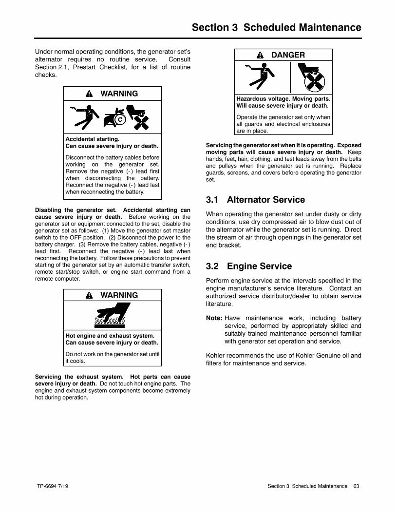
TP-6694 7/19 63Section 3 Scheduled Maintenance
Section 3 Scheduled Maintenance
Under normal operating conditions, the generator set’salternator requires no routine service. ConsultSection 2.1, Prestart Checklist, for a list of routinechecks.
Accidental starting.Can cause severe injury or death.
Disconnect the battery cables beforeworking on the generator set.Remove the negative (- ) lead firstwhen disconnecting the battery.Reconnect the negative (- ) lead lastwhen reconnecting the battery.
WARNING
Disabling the generator set. Accidental starting cancause severe injury or death. Before working on thegenerator set or equipment connected to the set, disable thegenerator set as follows: (1) Move the generator set masterswitch to the OFF position. (2) Disconnect the power to thebattery charger. (3) Remove the battery cables, negative (- )lead first. Reconnect the negative (- ) lead last whenreconnecting the battery. Follow these precautions to preventstarting of the generator set by an automatic transfer switch,remote start/stop switch, or engine start command from aremote computer.
Hot engine and exhaust system.Can cause severe injury or death.
Do not work on the generator set untilit cools.
WARNING
Servicing the exhaust system. Hot parts can causesevere injury or death. Do not touch hot engine parts. Theengine and exhaust system components become extremelyhot during operation.
Hazardous voltage. Moving parts.Will cause severe injury or death.
Operate the generator set only whenall guards and electrical enclosuresare in place.
DANGER
Servicing the generator setwhen it is operating. Exposedmoving parts will cause severe injury or death. Keephands, feet, hair, clothing, and test leads away from the beltsand pulleys when the generator set is running. Replaceguards, screens, and covers before operating the generatorset.
3.1 Alternator Service
When operating the generator set under dusty or dirtyconditions, use dry compressed air to blow dust out ofthe alternator while the generator set is running. Directthe stream of air through openings in the generator setend bracket.
3.2 Engine Service
Perform engine service at the intervals specified in theengine manufacturer’s service literature. Contact anauthorized service distributor/dealer to obtain serviceliterature.
Note: Have maintenance work, including batteryservice, performed by appropriately skilled andsuitably trained maintenance personnel familiarwith generator set operation and service.
Kohler recommends the use of Kohler Genuine oil andfilters for maintenance and service.
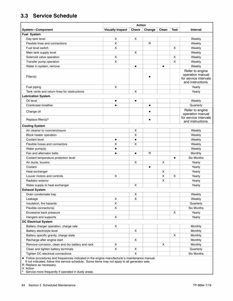
TP-6694 7/1964 Section 3 Scheduled Maintenance
3.3 Service Schedule
Action
System—Component Visually Inspect Check Change Clean Test Interval
Fuel System
Day tank level X X Weekly
Flexible lines and connections X R Weekly
Fuel level switch X X Weekly
Main tank supply level X Weekly
Solenoid valve operation X X Weekly
Transfer pump operation X X Weekly
Water in system, remove D D Weekly
Filter(s) D
Refer to engineoperation manualfor service intervalsand instructions.
Fuel piping X Yearly
Tank vents and return lines for obstructions X Yearly
Lubrication System
Oil level D D Weekly
Crankcase breather D D Quarterly
Change oil D Refer to engineoperation manualfor service intervalsand instructions.Replace filter(s)* D
Cooling System
Air cleaner to room/enclosure X Weekly
Block heater operation X Weekly
Coolant level D D Weekly
Flexible hoses and connectors X X Weekly
Water pump(s) D Weekly
Fan and alternator belts D D R Monthly
Coolant temperature protection level D Six Months
Air ducts, louvers X X Yearly
Coolant D Yearly
Heat exchanger X Yearly
Louver motors and controls X X X Yearly
Radiator exterior X Yearly
Water supply to heat exchanger X Yearly
Exhaust System
Drain condensate trap X Weekly
Leakage X X Weekly
Insulation, fire hazards X Quarterly
Flexible connector(s) X Six Months
Excessive back pressure X Yearly
Hangers and supports X Yearly
DC Electrical System
Battery charger operation, charge rate X Monthly
Battery electrolyte level X Monthly
Battery specific gravity, charge state X Monthly
Recharge after engine start X Monthly
Remove corrosion, clean and dry battery and rack X X Monthly
Clean and tighten battery terminals X X Quarterly
Tighten DC electrical connections X Six Months
D Follow procedures and frequencies indicated in the engine manufacturer’s maintenance manual.If not indicated, follow this service schedule. Some items may not apply to all generator sets.
R Replace as necessary.X Action* Service more frequently if operated in dusty areas.
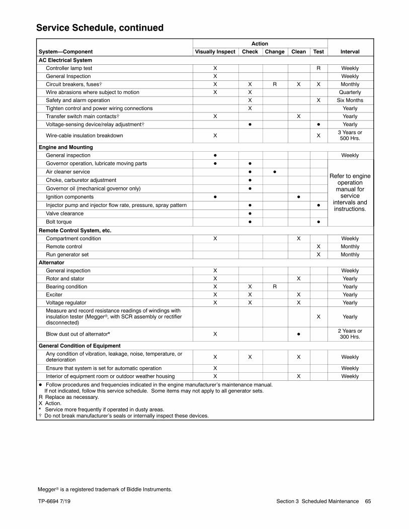
TP-6694 7/19 65Section 3 Scheduled Maintenance
Service Schedule, continued
Action
System—Component Visually Inspect Check Change Clean Test Interval
AC Electrical System
Controller lamp test X R Weekly
General Inspection X Weekly
Circuit breakers, fuses[ X X R X X Monthly
Wire abrasions where subject to motion X X Quarterly
Safety and alarm operation X X Six Months
Tighten control and power wiring connections X Yearly
Transfer switch main contacts[ X X Yearly
Voltage-sensing device/relay adjustment[ D D Yearly
Wire-cable insulation breakdown X X3 Years or500 Hrs.
Engine and Mounting
General inspection D Weekly
Governor operation, lubricate moving parts D D
Refer to engineoperationmanual forservice
intervals andinstructions.
Air cleaner service D D
Choke, carburetor adjustment D
Governor oil (mechanical governor only) D
Ignition components D D
Injector pump and injector flow rate, pressure, spray pattern D D
Valve clearance D
Bolt torque D D
Remote Control System, etc.
Compartment condition X X Weekly
Remote control X Monthly
Run generator set X Monthly
Alternator
General inspection X Weekly
Rotor and stator X X Yearly
Bearing condition X X R Yearly
Exciter X X X Yearly
Voltage regulator X X X Yearly
Measure and record resistance readings of windings withinsulation tester (Meggerr, with SCR assembly or rectifierdisconnected)
X Yearly
Blow dust out of alternator* X D2 Years or300 Hrs.
General Condition of Equipment
Any condition of vibration, leakage, noise, temperature, ordeterioration X X X Weekly
Ensure that system is set for automatic operation X Weekly
Interior of equipment room or outdoor weather housing X X Weekly
D Follow procedures and frequencies indicated in the engine manufacturer’s maintenance manual.If not indicated, follow this service schedule. Some items may not apply to all generator sets.
R Replace as necessary.X Action.* Service more frequently if operated in dusty areas.[ Do not break manufacturer’s seals or internally inspect these devices.
Meggerr is a registered trademark of Biddle Instruments.
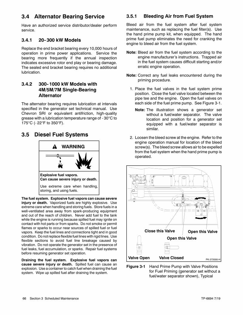
TP-6694 7/1966 Section 3 Scheduled Maintenance
3.4 Alternator Bearing Service
Have an authorized service distributor/dealer performservice.
3.4.1 20- 300 kW Models
Replace the end bracket bearing every 10,000 hours ofoperation in prime power applications. Service thebearing more frequently if the annual inspectionindicates excessive rotor end play or bearing damage.The sealed end bracket bearing requires no additionallubrication.
3.4.2 300- 1000 kW Models with4M/5M/7M Single-BearingAlternator
The alternator bearing requires lubrication at intervalsspecified in the generator set technical manual. UseChevron SRI or equivalent antifriction, high-qualitygrease with a lubrication temperature range of - 30C to175C (- 22F to 350F).
3.5 Diesel Fuel Systems
Explosive fuel vapors.Can cause severe injury or death.
Use extreme care when handling,storing, and using fuels.
WARNING
The fuel system. Explosive fuel vapors can cause severeinjury or death. Vaporized fuels are highly explosive. Useextreme care when handling and storing fuels. Store fuels in awell-ventilated area away from spark-producing equipmentand out of the reach of children. Never add fuel to the tankwhile the engine is running because spilled fuel may ignite oncontact with hot parts or from sparks. Do not smoke or permitflames or sparks to occur near sources of spilled fuel or fuelvapors. Keep the fuel lines and connections tight and in goodcondition. Donot replace flexible fuel lineswith rigid lines. Useflexible sections to avoid fuel line breakage caused byvibration. Do not operate the generator set in the presence offuel leaks, fuel accumulation, or sparks. Repair fuel systemsbefore resuming generator set operation.
Draining the fuel system. Explosive fuel vapors cancause severe injury or death. Spilled fuel can cause anexplosion. Use a container to catch fuel when draining the fuelsystem. Wipe up spilled fuel after draining the system.
3.5.1 Bleeding Air from Fuel System
Bleed air from the fuel system after fuel systemmaintenance, such as replacing the fuel filter(s). Usethe hand prime pump kit, when equipped. The handprime fuel pump eliminates the need for cranking theengine to bleed air from the fuel system.
Note: Bleed air from the fuel system according to theengine manufacturer’s instructions. Trapped airin the fuel system causes difficult starting and/orerratic engine operation.
Note: Correct any fuel leaks encountered during thepriming procedure.
1. Place the fuel valves in the fuel system primeposition. Close the fuel valve located between thepipe tee and the engine. Open the fuel valves oneach side of the fuel prime pump. See Figure 3-1.
Note: The illustration shows a generator setwithout a fuel/water separator. The valvelocation and position for a generator setequipped with a fuel/water separator issimilar.
2. Loosen the bleed screw at the engine. Refer to theengine operation manual for location of the bleedscrew(s). The bleed screwallowsair to beexpelledfrom the fuel system when the hand prime pump isoperated.
PK-272000-HValve Open Valve Closed
Close this Valve Open this Valve
Open this Valve
Figure 3-1 Hand Prime Pump with Valve Positionsfor Fuel Priming (generator set without afuel/water separator shown), Typical
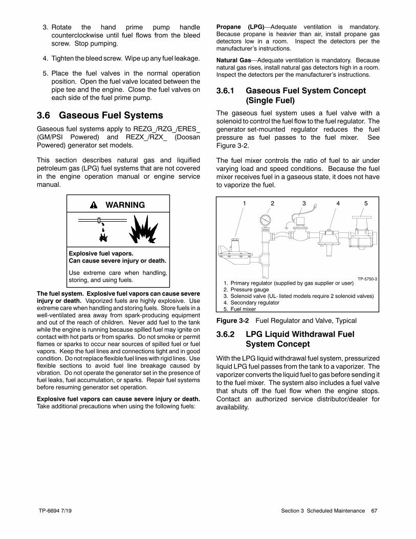
TP-6694 7/19 67Section 3 Scheduled Maintenance
3. Rotate the hand prime pump handlecounterclockwise until fuel flows from the bleedscrew. Stop pumping.
4. Tighten the bleed screw. Wipe upany fuel leakage.
5. Place the fuel valves in the normal operationposition. Open the fuel valve located between thepipe tee and the engine. Close the fuel valves oneach side of the fuel prime pump.
3.6 Gaseous Fuel SystemsGaseous fuel systems apply to REZG_/RZG_/ERES_(GM/PSI Powered) and REZX_/RZX_ (DoosanPowered) generator set models.
This section describes natural gas and liquifiedpetroleum gas (LPG) fuel systems that are not coveredin the engine operation manual or engine servicemanual.
Explosive fuel vapors.Can cause severe injury or death.
Use extreme care when handling,storing, and using fuels.
WARNING
The fuel system. Explosive fuel vapors can cause severeinjury or death. Vaporized fuels are highly explosive. Useextreme care when handling and storing fuels. Store fuels in awell-ventilated area away from spark-producing equipmentand out of the reach of children. Never add fuel to the tankwhile the engine is running because spilled fuel may ignite oncontact with hot parts or from sparks. Do not smoke or permitflames or sparks to occur near sources of spilled fuel or fuelvapors. Keep the fuel lines and connections tight and in goodcondition. Donot replace flexible fuel lineswith rigid lines. Useflexible sections to avoid fuel line breakage caused byvibration. Do not operate the generator set in the presence offuel leaks, fuel accumulation, or sparks. Repair fuel systemsbefore resuming generator set operation.
Explosive fuel vapors can cause severe injury or death.Take additional precautions when using the following fuels:
Propane (LPG)—Adequate ventilation is mandatory.Because propane is heavier than air, install propane gasdetectors low in a room. Inspect the detectors per themanufacturer’s instructions.
Natural Gas—Adequate ventilation is mandatory. Becausenatural gas rises, install natural gas detectors high in a room.Inspect the detectors per the manufacturer’s instructions.
3.6.1 Gaseous Fuel System Concept(Single Fuel)
The gaseous fuel system uses a fuel valve with asolenoid to control the fuel flow to the fuel regulator. Thegenerator set-mounted regulator reduces the fuelpressure as fuel passes to the fuel mixer. SeeFigure 3-2.
The fuel mixer controls the ratio of fuel to air undervarying load and speed conditions. Because the fuelmixer receives fuel in a gaseous state, it does not haveto vaporize the fuel.
TP-5750-31. Primary regulator (supplied by gas supplier or user)2. Pressure gauge3. Solenoid valve (UL- listed models require 2 solenoid valves)4. Secondary regulator5. Fuel mixer
1 2 3 4 5
Figure 3-2 Fuel Regulator and Valve, Typical
3.6.2 LPG Liquid Withdrawal FuelSystem Concept
With the LPG liquid withdrawal fuel system, pressurizedliquid LPG fuel passes from the tank to a vaporizer. Thevaporizer converts the liquid fuel to gas before sending itto the fuel mixer. The system also includes a fuel valvethat shuts off the fuel flow when the engine stops.Contact an authorized service distributor/dealer foravailability.
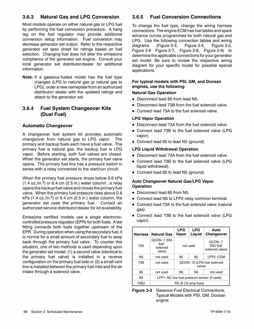
TP-6694 7/1968 Section 3 Scheduled Maintenance
3.6.3 Natural Gas and LPG ConversionMost models operate on either natural gas or LPG fuelby performing the fuel conversion procedure. A hangtag on the fuel regulator may provide additionalconversion setup information. Fuel conversion maydecrease generator set output. Refer to the respectivegenerator set spec sheet for ratings based on fuelselection. Changing fuel does not alter the emissionscompliance of the generator set engine. Consult yourlocal generator set distributor/dealer for additionalinformation.
Note: If a gaseous-fueled model has the fuel typechanged (LPG to natural gas or natural gas toLPG), order a new nameplate from an authorizeddistributor/ dealer with the updated ratings andattach to the generator set.
3.6.4 Fuel System Changeover Kits(Dual Fuel)
Automatic Changeover
A changeover fuel system kit provides automaticchangeover from natural gas to LPG vapor. Theprimary and backup fuels each have a fuel valve. Theprimary fuel is natural gas; the backup fuel is LPGvapor. Before starting, both fuel valves are closed.When the generator set starts, the primary fuel valveopens. The primary fuel line has a pressure switch inseries with a relay connected to the start/run circuit.
When the primary fuel pressure drops below 0.6 kPa(1.4 oz./in.2) or 6.4 cm (2.5 in.) water column , a relayopens the backup fuel valve and closes the primary fuelvalve. When the primary fuel pressure rises above 0.6kPa (1.4 oz./in.2) or 6.4 cm (2.5 in.) water column, thegenerator set uses the primary fuel. Contact anauthorized service distributor/dealer for kit availability.
Emissions certified models use a single electronic-controlled pressure regulator (EPR) for both fuels. A teefitting connects both fuels together upstream of theEPR. During operationwhenusing the secondary fuel, itis normal for a small amount of secondary fuel to seepback through the primary fuel valve. To counter thissituation, one of two methods is used depending uponthe generator set model: (1) a second valve (identical tothe primary fuel valve) is installed in a reverseconfiguration on the primary fuel side or (2) a small ventline is installed between the primary fuel inlet and the airintake through a solenoid valve.
3.6.5 Fuel Conversion Connections
To change the fuel type, change the wiring harnessconnections. The engine ECMhas fuel tables and sparkadvance curves programmed for both natural gas andLPG. Use the following connection tables and wiringdiagrams (Figure 3-3, Figure 3-4, Figure 3-5,Figure 3-6 Figure 3-7, Figure 3-8, Figure 3-9) todetermine theapplicable connections for your generatorset model. Be sure to review the respective wiringdiagram for your specific model for possible specialapplications.
For typical models with PSI, GM, and Doosanengines, use the following:
Natural Gas Operation
D Disconnect lead 65 from lead N5.
D Disconnect lead 73B from the fuel solenoid valve.
D Connect lead 73A to the fuel solenoid valve.
LPG Vapor Operation
D Disconnect lead 73A from the fuel solenoid valve.
D Connect lead 73B to the fuel solenoid valve (LPGvapor).
D Connect lead 65 to lead N5 (ground).
LPG Liquid Withdrawal Operation
D Disconnect lead 73A from the fuel solenoid valve.
D Connect lead 73B to the fuel solenoid valve (LPGliquid withdrawal).
D Connect lead 65 to lead N5 (ground).
Auto Changeover Natural Gas/LPG VaporOperation
D Disconnect lead 65 from N5.
D Connect lead N5 to LFP2 relay common terminal.D Connect lead 73A to the fuel solenoid valve (naturalgas).
D Connect lead 73B to the fuel solenoid valve (LPGvapor).
Harness Natural GasLPGVapor
LPGLiquid
AutoChangeover
73A
QCON- 7 (NGfuel
solenoidvalve)
not usedQCON- 7(NG fuel
solenoid valve)
N5 not used 65 65 LFP2-COM
73B not used QCON- 10 (LPG fuel solenoidvalve)
65 not used N5 N5 not used
63 LFP1-NC low fuel pressure sensor (if used)
70E2 P6- B (15 amp fuse)
Figure 3-3 Gaseous Fuel Electrical Connections,Typical Models with PSI, GM, Doosanengine
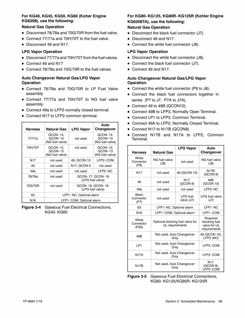
TP-6694 7/19 69Section 3 Scheduled Maintenance
For KG40, KG45, KG50, KG60 (Koher EngineKG6208), use the following:
Natural Gas Operation
D Disconnect 78/78a and 70G/70R from the fuel valve.
D Connect 77/77a and 70H/70T to the fuel valve.
D Disconnect 49 and N17.
LPG Vapor Operation
D Disconnect 77/77a and 70H/70T from the fuel valves.
D Connect 49 and N17
D Connect 78/78a and 70G/70R to the fuel valves.
Auto Changeover Natural Gas/LPG VaporOperation
D Connect 78/78a and 70G/70R to LP Fuel Valveassembly.
D Connect 77/77a and 70H/70T to NG fuel valveassembly.
D Connect 49a to LFP2 normally closed terminal.
D Connect N17 to LFP2 common terminal.
Harness Natural Gas LPG VaporAuto
Changeover
77/77aQCON- 14,QCON- 15
(NG fuel valve)not used
QCON- 14,QCON- 15
(NG fuel valve)
70H/70T QCON- 12,QCON- 13
(NG fuel valve)
not used QCON- 12,QCON- 13
(NG fuel valve)
N17 not used 49, QCON 10 LFP2-COM
49 not used N17, QCON 9 not used
49a not used not used LFP2-NC
78/78a not used QCON- 17, QCON- 19(LPG fuel valve)
70G/70R not used QCON- 16, QCON- 18(LPG fuel valve)
63 LFP1-NC, Optional alarm
N16 LFP1-COM, Optional alarm
Figure 3-4 Gaseous Fuel Electrical Connections,KG40- KG60
For KG80- KG125, KG80R- KG125R (Kohler Engine KG6208TA), use the following:Natural Gas OperationD Disconnect the black fuel connector (J7).D Disconnect 49 and N17.D Connect the white fuel connector (J8).
LPG Vapor OperationD Disconnect the white fuel connector (J8).
D Connect the black fuel connector (J7).
D Connect 49 and N17.
Auto Changeover Natural Gas/LPG Vapor OperationD Connect the white fuel connector (P8 to J8).D Connect the black fuel connectors together inseries (P7 to J7, P7A to J7A).
D Connect 49 to 49B (QCON10).D Connect 49B to LFP3, Normally Open Terminal.D Connect LP1 to LFP3, Common Terminal.D Connect 49A to LFP2, Normally Closed Terminal. D Connect N17 to N17B (QCON9).D Connect N17B and N17A to LFP2, CommonTerminal.
Harness Natural GasLPG Vapor Auto
Changeover
WhiteConnector
(P8)
NG fuel valve(J8) not used
NG fuel valve(J8)
N17 not used 49 (QCON 10)N17B
(QCON 9)
49 not usedN17
(QCON 9)49B
(QCON 10)
49a not used not used LFP2-NC
BlackConnector
(P7)not used
LPG fuelvalve (J7)
LPG fuel valve(J7)
63 LFP1-NC, Optional alarm LFP1-NC
N16 LFP1-COM, Optional alarm LFP1-COM
WhiteConnector(P30)
Optional blocking fuel valve forUL requirements
Requiredblocking fuelvalve for ULrequirements
49BNot used, Auto Changeover
Only49 (QCON 10),LFP3 (NO)
LP1Not used, Auto Changeover
Only LFP3- COM
N17ANot used, Auto Changeover
Only LFP2- COM
N17BNot used, Auto Changeover
Only
N17(QCON 9),LFP2- COM
Figure 3-5 Gaseous Fuel Electrical Connections,KG80- KG125/KG80R- KG125R
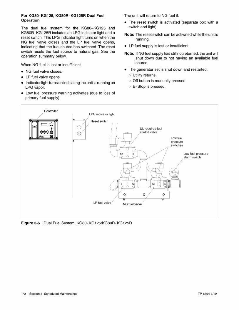
TP-6694 7/1970 Section 3 Scheduled Maintenance
For KG80-KG125, KG80R-KG125R Dual FuelOperation
The dual fuel system for the KG80–KG125 andKG80R–KG125R includes an LPG indicator light and areset switch. This LPG indicator light turns on when theNG fuel valve closes and the LP fuel valve opens,indicating that the fuel source has switched. The resetswitch resets the fuel source to natural gas. See theoperation summary below.
When NG fuel is lost or insufficient
D NG fuel valve closes.
D LP fuel valve opens.D Indicator light turns on indicating the unit is runningonLPG vapor.
D Low fuel pressure warning activates (due to loss ofprimary fuel supply).
The unit will return to NG fuel if:
D The reset switch is activated (separate box with aswitch and light).
Note: The reset switch can be activated while the unit isrunning.
D LP fuel supply is lost or insufficient.
Note: If NG fuel supply has still not returned, the unit willshut down due to not having an available fuelsource.
D The generator set is shut down and restarted.
d Utility returns.
d Off button is manually pressed.d E- Stop is pressed.
UL required fuelshutoff valve
Low fuelpressureswitches
Low fuel pressurealarm switch
NG fuel valveLP fuel valve
Reset switch
LPG indicator lightController
Figure 3-6 Dual Fuel System, KG80- KG125/KG80R- KG125R
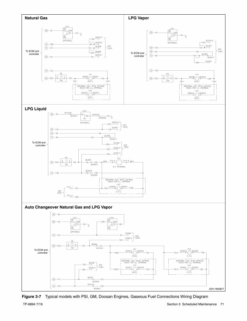
TP-6694 7/19 71Section 3 Scheduled Maintenance
ADV-7600B-F
Natural Gas LPG Vapor
LPG Liquid
Auto Changeover Natural Gas and LPG Vapor
To ECM andcontroller To ECM and
controller
To ECM andcontroller
To ECM andcontroller
Figure 3-7 Typical models with PSI, GM, Doosan Engines, Gaseous Fuel Connections Wiring Diagram
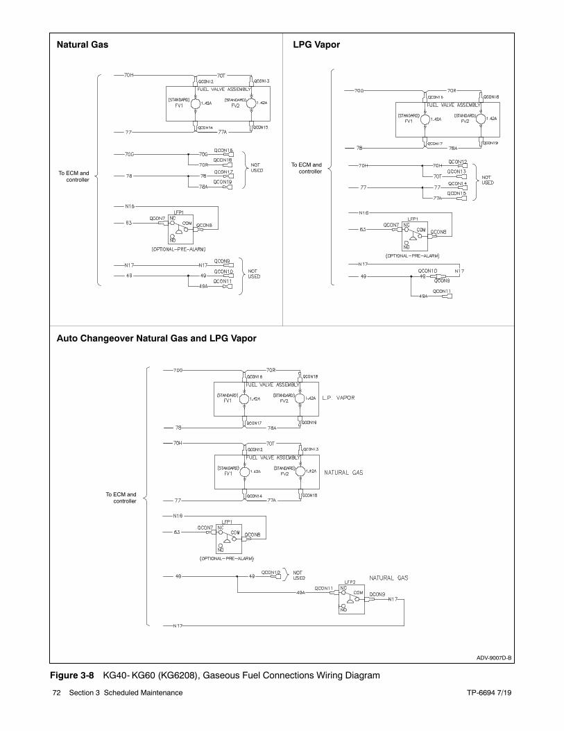
TP-6694 7/1972 Section 3 Scheduled Maintenance
ADV-9007D-B
Natural Gas LPG Vapor
Auto Changeover Natural Gas and LPG Vapor
To ECM andcontroller
To ECM andcontroller
To ECM andcontroller
Figure 3-8 KG40- KG60 (KG6208), Gaseous Fuel Connections Wiring Diagram
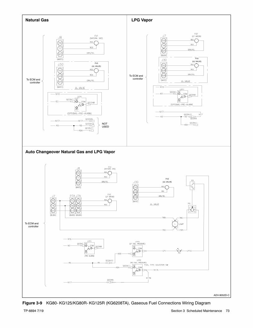
TP-6694 7/19 73Section 3 Scheduled Maintenance
ADV-9052D-C
Natural Gas LPG Vapor
Auto Changeover Natural Gas and LPG Vapor
To ECM andcontroller
To ECM andcontroller
To ECM andcontroller
NOTUSED
FV3
(UL VALVE)
FV3
(UL VALVE)
FV3
(UL VALVE)
Figure 3-9 KG80- KG125/KG80R- KG125R (KG6208TA), Gaseous Fuel Connections Wiring Diagram
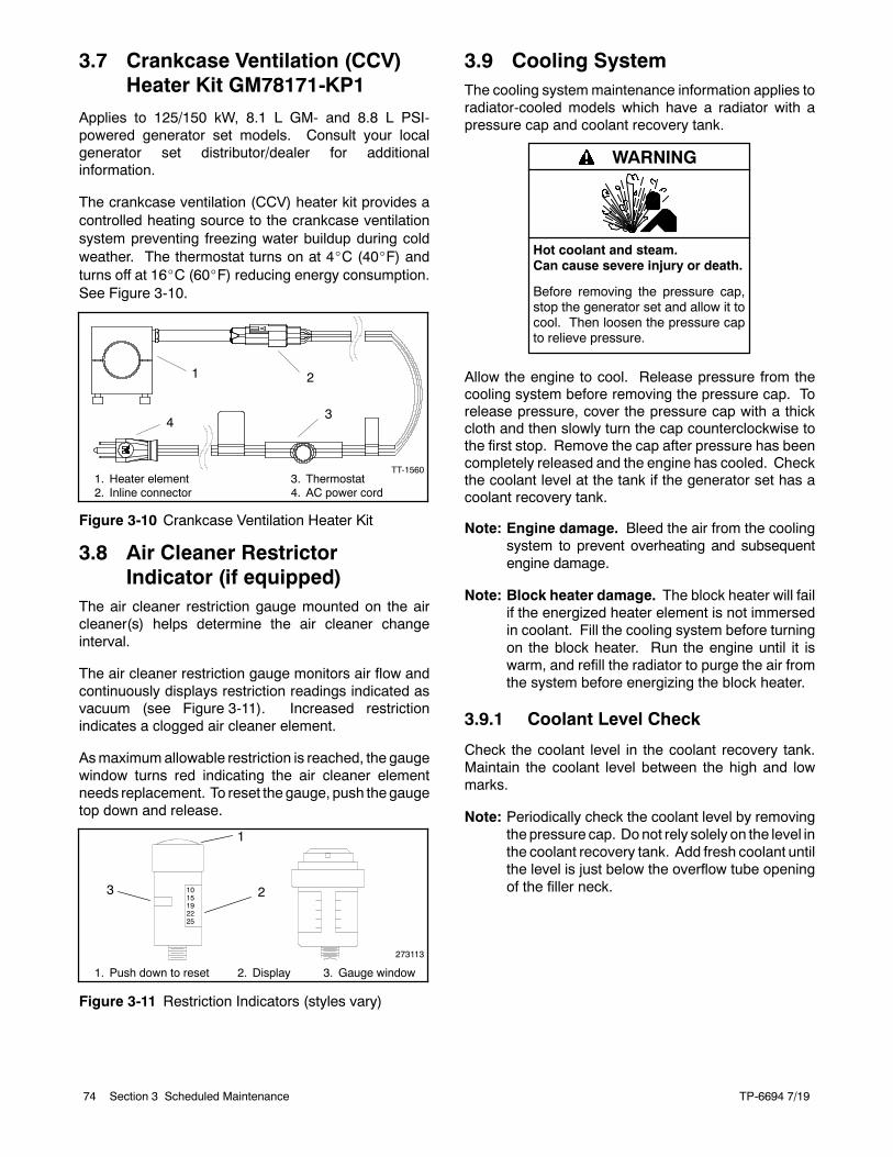
TP-6694 7/1974 Section 3 Scheduled Maintenance
3.7 Crankcase Ventilation (CCV)Heater Kit GM78171-KP1
Applies to 125/150 kW, 8.1 L GM- and 8.8 L PSI-powered generator set models. Consult your localgenerator set distributor/dealer for additionalinformation.
The crankcase ventilation (CCV) heater kit provides acontrolled heating source to the crankcase ventilationsystem preventing freezing water buildup during coldweather. The thermostat turns on at 4_C (40_F) andturns off at 16_C (60_F) reducing energy consumption.See Figure 3-10.
1. Heater element2. Inline connector
TT-1560
1 2
34
3. Thermostat4. AC power cord
Figure 3-10 Crankcase Ventilation Heater Kit
3.8 Air Cleaner RestrictorIndicator (if equipped)
The air cleaner restriction gauge mounted on the aircleaner(s) helps determine the air cleaner changeinterval.
The air cleaner restriction gauge monitors air flow andcontinuously displays restriction readings indicated asvacuum (see Figure 3-11). Increased restrictionindicates a clogged air cleaner element.
Asmaximumallowable restriction is reached, the gaugewindow turns red indicating the air cleaner elementneeds replacement. To reset the gauge, push thegaugetop down and release.
273113
1015192225
1
23
1. Push down to reset 2. Display 3. Gauge window
Figure 3-11 Restriction Indicators (styles vary)
3.9 Cooling SystemThe cooling systemmaintenance information applies toradiator-cooled models which have a radiator with apressure cap and coolant recovery tank.
Hot coolant and steam.Can cause severe injury or death.
Before removing the pressure cap,stop the generator set and allow it tocool. Then loosen the pressure capto relieve pressure.
WARNING
Allow the engine to cool. Release pressure from thecooling system before removing the pressure cap. Torelease pressure, cover the pressure cap with a thickcloth and then slowly turn the cap counterclockwise tothe first stop. Remove the cap after pressure has beencompletely released and the engine has cooled. Checkthe coolant level at the tank if the generator set has acoolant recovery tank.
Note: Engine damage. Bleed the air from the coolingsystem to prevent overheating and subsequentengine damage.
Note: Block heater damage. The block heater will failif the energized heater element is not immersedin coolant. Fill the cooling system before turningon the block heater. Run the engine until it iswarm, and refill the radiator to purge the air fromthe system before energizing the block heater.
3.9.1 Coolant Level Check
Check the coolant level in the coolant recovery tank.Maintain the coolant level between the high and lowmarks.
Note: Periodically check the coolant level by removingthe pressure cap. Donot rely solely on the level inthe coolant recovery tank. Add fresh coolant untilthe level is just below the overflow tube openingof the filler neck.
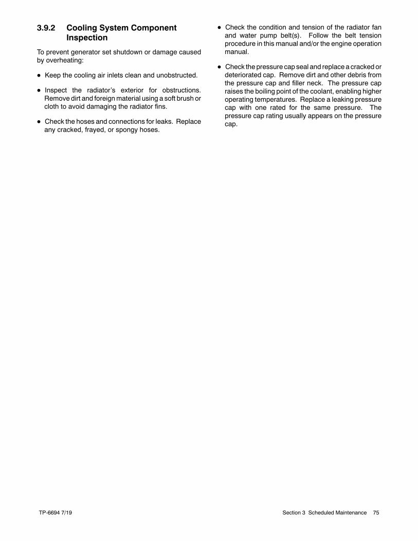
TP-6694 7/19 75Section 3 Scheduled Maintenance
3.9.2 Cooling System ComponentInspection
To prevent generator set shutdown or damage causedby overheating:
D Keep the cooling air inlets clean and unobstructed.
D Inspect the radiator’s exterior for obstructions.Remove dirt and foreignmaterial using a soft brush orcloth to avoid damaging the radiator fins.
D Check the hoses and connections for leaks. Replaceany cracked, frayed, or spongy hoses.
D Check the condition and tension of the radiator fanand water pump belt(s). Follow the belt tensionprocedure in this manual and/or the engine operationmanual.
D Check thepressure cap seal and replacea crackedordeteriorated cap. Remove dirt and other debris fromthe pressure cap and filler neck. The pressure capraises the boiling point of the coolant, enabling higheroperating temperatures. Replace a leaking pressurecap with one rated for the same pressure. Thepressure cap rating usually appears on the pressurecap.
TP-6694 7/1976 Section 3 Scheduled Maintenance
3.9.3 Procedure to Drain CoolingSystem
For optimum protection, drain, flush, and refill thecooling system at the intervals listed in the serviceschedule.
Note: Dispose of all waste materials (oil, fuel, coolant,filters, and gaskets) in an environmentally safemanner.
1. Deenergize the block heater, if equipped.
2. Remove the pressure cap to allow the entiresystem to drain and prevent air pockets fromrestricting coolant flow through the engine block.
3. Open the radiator and/or engine block coolantdrain valve(s) and allow the system to drain.
4. If the inside of the radiator has mineral deposits orthe used coolant contains dirt or grease, refer toSection 3.9.4, Procedure to Flush and Clean theCooling System. If the cooling system does nothave mineral deposits, go to Section 3.9.5,Procedure to Refill the Cooling System.
3.9.4 Procedure to Flush and CleanCooling System
Use the instructions in the engine operation manualwhen available to flush and clean the cooling system.Otherwise, use the following procedure and the coolingsystem cleaner manufacturer’s instructions.
1. Flush the cooling system with clean water.
2. If the inside of the radiator still has mineraldeposits, use a radiator cleaner to remove theremaining deposits following the manufacturer’sinstructions.
3. Drain, clean, and flush the coolant recovery tank.
3.9.5 Procedure to Refill CoolingSystem
See the generator set spec sheet for coolant capacity.
Note: Do not add coolant to a hot engine. Addingcoolant to a hot engine can cause the cylinderblock or cylinder head to crack. Wait until theengine has cooled.
1. Remove the pressure cap.
2. Close the radiator and/or engine block coolantdrain valve(s) and tighten the cooling system hoseclamps.
3. Open the air-bleed petcocks, if equipped. Closethe air-bleed petcocks when coolant begins to flowfrom them.
4. Add coolant additives or water pump lubricantsaccording to the engine manufacturer’srecommendations in the engine operation manual.
5. Fill the cooling system with a coolant/antifreezemixture based on the engine manufacturer’srecommendation.
6. Replace the pressure cap.
7. Fill the coolant recovery tank to the low mark.
8. Operate generator set until the thermostat openswhen the upper cooling system hose warms.
9. Stop the engine and allow it to cool.
10. Check and repair any coolant leaks.
11. Remove the pressure cap.
12. Add coolant to bring the coolant level to just belowthe overflow tube opening of the filler neck.
13. Replace the pressure cap.
14. Maintain the coolant level in the coolant recoverytank between the high and low marks.
Air pockets often form in the engine water jacketwhen the coolant system is refilled. Check thecoolant level in the coolant recovery tank after eachgenerator set operation and add coolant asnecessary until the coolant level stabilizes. Thencheck the coolant at the interval specified in theservice schedule.
15. Reenergize the block heater, if equipped.
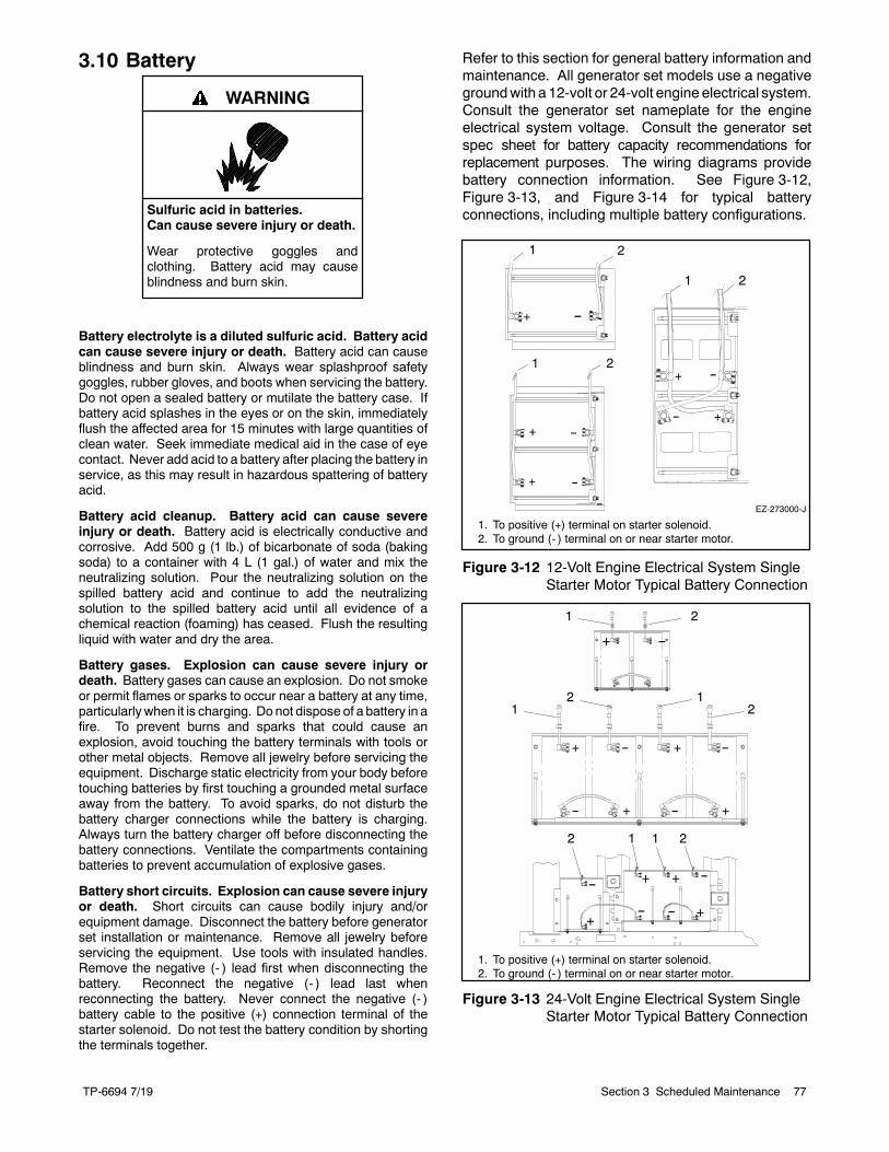
TP-6694 7/19 77Section 3 Scheduled Maintenance
3.10 Battery
Sulfuric acid in batteries.Can cause severe injury or death.
Wear protective goggles andclothing. Battery acid may causeblindness and burn skin.
WARNING
Battery electrolyte is a diluted sulfuric acid. Battery acidcan cause severe injury or death. Battery acid can causeblindness and burn skin. Always wear splashproof safetygoggles, rubber gloves, and boots when servicing the battery.Do not open a sealed battery or mutilate the battery case. Ifbattery acid splashes in the eyes or on the skin, immediatelyflush the affected area for 15 minutes with large quantities ofclean water. Seek immediate medical aid in the case of eyecontact. Never add acid to a battery after placing the battery inservice, as this may result in hazardous spattering of batteryacid.
Battery acid cleanup. Battery acid can cause severeinjury or death. Battery acid is electrically conductive andcorrosive. Add 500 g (1 lb.) of bicarbonate of soda (bakingsoda) to a container with 4 L (1 gal.) of water and mix theneutralizing solution. Pour the neutralizing solution on thespilled battery acid and continue to add the neutralizingsolution to the spilled battery acid until all evidence of achemical reaction (foaming) has ceased. Flush the resultingliquid with water and dry the area.
Battery gases. Explosion can cause severe injury ordeath. Battery gases can cause an explosion. Do not smokeor permit flames or sparks to occur near a battery at any time,particularly when it is charging. Do not dispose of a battery in afire. To prevent burns and sparks that could cause anexplosion, avoid touching the battery terminals with tools orother metal objects. Remove all jewelry before servicing theequipment. Discharge static electricity from your body beforetouching batteries by first touching a grounded metal surfaceaway from the battery. To avoid sparks, do not disturb thebattery charger connections while the battery is charging.Always turn the battery charger off before disconnecting thebattery connections. Ventilate the compartments containingbatteries to prevent accumulation of explosive gases.
Battery short circuits. Explosion can cause severe injuryor death. Short circuits can cause bodily injury and/orequipment damage. Disconnect the battery before generatorset installation or maintenance. Remove all jewelry beforeservicing the equipment. Use tools with insulated handles.Remove the negative (- ) lead first when disconnecting thebattery. Reconnect the negative (- ) lead last whenreconnecting the battery. Never connect the negative (- )battery cable to the positive (+) connection terminal of thestarter solenoid. Do not test the battery condition by shortingthe terminals together.
Refer to this section for general battery information andmaintenance. All generator set models use a negativegroundwith a 12-volt or 24-volt engine electrical system.Consult the generator set nameplate for the engineelectrical system voltage. Consult the generator setspec sheet for battery capacity recommendations forreplacement purposes. The wiring diagrams providebattery connection information. See Figure 3-12,Figure 3-13, and Figure 3-14 for typical batteryconnections, including multiple battery configurations.
EZ-273000-J
1 2
1 2
1 2
1. To positive (+) terminal on starter solenoid.2. To ground (- ) terminal on or near starter motor.
Figure 3-12 12-Volt Engine Electrical System SingleStarter Motor Typical Battery Connection
1
11
1 1
2
2
2
2
2
1. To positive (+) terminal on starter solenoid.2. To ground (- ) terminal on or near starter motor.
Figure 3-13 24-Volt Engine Electrical System SingleStarter Motor Typical Battery Connection
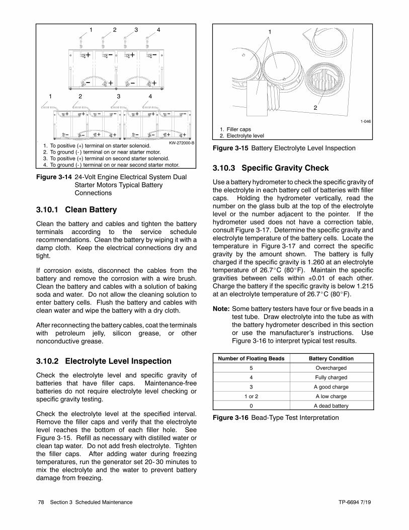
TP-6694 7/1978 Section 3 Scheduled Maintenance
4321
1 2 3 4
KW-272000-B1. To positive (+) terminal on starter solenoid.2. To ground (- ) terminal on or near starter motor.3. To positive (+) terminal on second starter solenoid.4. To ground (- ) terminal on or near second starter motor.
Figure 3-14 24-Volt Engine Electrical System DualStarter Motors Typical BatteryConnections
3.10.1 Clean Battery
Clean the battery and cables and tighten the batteryterminals according to the service schedulerecommendations. Clean the battery by wiping it with adamp cloth. Keep the electrical connections dry andtight.
If corrosion exists, disconnect the cables from thebattery and remove the corrosion with a wire brush.Clean the battery and cables with a solution of bakingsoda and water. Do not allow the cleaning solution toenter battery cells. Flush the battery and cables withclean water and wipe the battery with a dry cloth.
After reconnecting the battery cables, coat the terminalswith petroleum jelly, silicon grease, or othernonconductive grease.
3.10.2 Electrolyte Level Inspection
Check the electrolyte level and specific gravity ofbatteries that have filler caps. Maintenance-freebatteries do not require electrolyte level checking orspecific gravity testing.
Check the electrolyte level at the specified interval.Remove the filler caps and verify that the electrolytelevel reaches the bottom of each filler hole. SeeFigure 3-15. Refill as necessary with distilled water orclean tap water. Do not add fresh electrolyte. Tightenthe filler caps. After adding water during freezingtemperatures, run the generator set 20- 30 minutes tomix the electrolyte and the water to prevent batterydamage from freezing.
1-046
1
2
1. Filler caps2. Electrolyte level
Figure 3-15 Battery Electrolyte Level Inspection
3.10.3 Specific Gravity Check
Use a battery hydrometer to check the specific gravity ofthe electrolyte in each battery cell of batteries with fillercaps. Holding the hydrometer vertically, read thenumber on the glass bulb at the top of the electrolytelevel or the number adjacent to the pointer. If thehydrometer used does not have a correction table,consult Figure 3-17. Determine the specific gravity andelectrolyte temperature of the battery cells. Locate thetemperature in Figure 3-17 and correct the specificgravity by the amount shown. The battery is fullycharged if the specific gravity is 1.260 at an electrolytetemperature of 26.7_C (80_F). Maintain the specificgravities between cells within 0.01 of each other.Charge the battery if the specific gravity is below 1.215at an electrolyte temperature of 26.7_C (80_F).
Note: Some battery testers have four or five beads in atest tube. Draw electrolyte into the tube as withthe battery hydrometer described in this sectionor use the manufacturer’s instructions. UseFigure 3-16 to interpret typical test results.
Number of Floating Beads Battery Condition
5 Overcharged
4 Fully charged
3 A good charge
1 or 2 A low charge
0 A dead battery
Figure 3-16 Bead-Type Test Interpretation
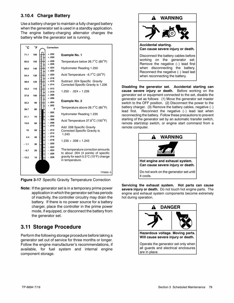
TP-6694 7/19 79Section 3 Scheduled Maintenance
3.10.4 Charge Battery
Use a battery charger tomaintain a fully charged batterywhen the generator set is used in a standby application.The engine battery-charging alternator charges thebattery while the generator set is running.
10
20
30
40
50
60
70
80
90
100
110
120
130
140
150
160
- 12.2
- 6.7
- 1.1
4.4
10
21.1
26.7
32.2
37.8
43.3
48.9
54.4
60.0
65.6
71.1
15.6
+ .032+ .030
+ .028+ .026
+ .024+ .022
+ .020
+ .018+ .016+ .014
+ .012+ .010+ .008+ .006
+ .004+ .002
- .002
- .004- . 006- .008- .010
- .012- .014- .016- .018
- .020
- .022- .024- .026
- .028
C F
Example No. 1
Temperature below 26.7C (80F)
Hydrometer Reading 1.250
Acid Temperature - 6.7C (20F)
Subtract .024 Specific GravityCorrected Specific Gravity is 1.226
1.250 - .024 = 1.226
Example No. 2
Temperature above 26.7C (80F)
Hydrometer Reading 1.235
Acid Temperature 37.8C (100F)
Add .008 Specific GravityCorrected Specific Gravity is1.243
1.235 + .008 = 1.243
The temperature correction amountsto about .004 (4 points) of specificgravity for each 5.5C (10F) changein temperature.
Correction
TP6895- 6
0
Figure 3-17 Specific Gravity Temperature Correction
Note: If the generator set is in a temporary prime powerapplication inwhich the generator set has periodsof inactivity, the controller circuitry may drain thebattery. If there is no power source for a batterycharger, place the controller in the prime powermode, if equipped, or disconnect the battery fromthe generator set.
3.11 Storage Procedure
Perform the following storage procedure before taking agenerator set out of service for three months or longer.Follow the engine manufacturer’s recommendations, ifavailable, for fuel system and internal enginecomponent storage.
Accidental starting.Can cause severe injury or death.
Disconnect the battery cables beforeworking on the generator set.Remove the negative (- ) lead firstwhen disconnecting the battery.Reconnect the negative (- ) lead lastwhen reconnecting the battery.
WARNING
Disabling the generator set. Accidental starting cancause severe injury or death. Before working on thegenerator set or equipment connected to the set, disable thegenerator set as follows: (1) Move the generator set masterswitch to the OFF position. (2) Disconnect the power to thebattery charger. (3) Remove the battery cables, negative (- )lead first. Reconnect the negative (- ) lead last whenreconnecting the battery. Follow these precautions to preventstarting of the generator set by an automatic transfer switch,remote start/stop switch, or engine start command from aremote computer.
Hot engine and exhaust system.Can cause severe injury or death.
Do not work on the generator set untilit cools.
WARNING
Servicing the exhaust system. Hot parts can causesevere injury or death. Do not touch hot engine parts. Theengine and exhaust system components become extremelyhot during operation.
Hazardous voltage. Moving parts.Will cause severe injury or death.
Operate the generator set only whenall guards and electrical enclosuresare in place.
DANGER
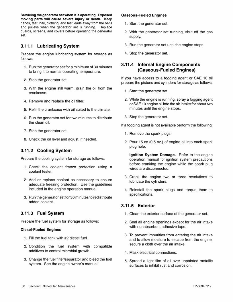
TP-6694 7/1980 Section 3 Scheduled Maintenance
Servicing the generator set when it is operating. Exposedmoving parts will cause severe injury or death. Keephands, feet, hair, clothing, and test leads away from the beltsand pulleys when the generator set is running. Replaceguards, screens, and covers before operating the generatorset.
3.11.1 Lubricating System
Prepare the engine lubricating system for storage asfollows:
1. Run the generator set for aminimum of 30minutesto bring it to normal operating temperature.
2. Stop the generator set.
3. With the engine still warm, drain the oil from thecrankcase.
4. Remove and replace the oil filter.
5. Refill the crankcase with oil suited to the climate.
6. Run the generator set for two minutes to distributethe clean oil.
7. Stop the generator set.
8. Check the oil level and adjust, if needed.
3.11.2 Cooling System
Prepare the cooling system for storage as follows:
1. Check the coolant freeze protection using acoolant tester.
2. Add or replace coolant as necessary to ensureadequate freezing protection. Use the guidelinesincluded in the engine operation manual.
3. Run the generator set for 30minutes to redistributeadded coolant.
3.11.3 Fuel System
Prepare the fuel system for storage as follows:
Diesel-Fueled Engines
1. Fill the fuel tank with #2 diesel fuel.
2. Condition the fuel system with compatibleadditives to control microbial growth.
3. Change the fuel filter/separator and bleed the fuelsystem. See the engine owner’s manual.
Gaseous-Fueled Engines
1. Start the generator set.
2. With the generator set running, shut off the gassupply.
3. Run the generator set until the engine stops.
4. Stop the generator set.
3.11.4 Internal Engine Components(Gaseous-Fueled Engines)
If you have access to a fogging agent or SAE 10 oilprepare the pistons and cylinders for storage as follows:
1. Start the generator set.
2. While the engine is running, spray a fogging agentor SAE10 engine oil into the air intake for about twominutes until the engine stops.
3. Stop the generator set.
If a fogging agent is not available perform the following:
1. Remove the spark plugs.
2. Pour 15 cc (0.5 oz.) of engine oil into each sparkplug hole.
Ignition System Damage. Refer to the engineoperation manual for ignition system precautionsbefore cranking the engine while the spark plugwires are disconnected.
3. Crank the engine two or three revolutions tolubricate the cylinders.
4. Reinstall the spark plugs and torque them tospecifications.
3.11.5 Exterior
1. Clean the exterior surface of the generator set.
2. Seal all engine openings except for the air intakewith nonabsorbent adhesive tape.
3. To prevent impurities from entering the air intakeand to allow moisture to escape from the engine,secure a cloth over the air intake.
4. Mask electrical connections.
5. Spread a light film of oil over unpainted metallicsurfaces to inhibit rust and corrosion.

TP-6694 7/19 81Section 3 Scheduled Maintenance
3.11.6 Battery
Perform battery storage after all other storageprocedures.
1. Confirm that the generator set is stopped.
2. Disconnect the battery(ies), negative (- ) lead first.
3. Clean the battery. Refer to Section 3.10.1 for thebattery cleaning procedure.
4. Place the battery in a cool, dry location.
5. Connect the battery to a battery charger or chargeitmonthlywith a trickle battery charger. Refer to thebattery chargermanufacturer’s recommendations.
Maintain a full charge to extend battery life.
TP-6694 7/1982
Section 4 General Troubleshooting
Section 4 General Troubleshooting
This section contains generator set troubleshooting,diagnostic, and repair information.
Use the following charts to diagnose and correctcommon problems. First check for simple causes suchas a dead engine starting battery or an open circuitbreaker. The charts include a list of common problems,possible causes of the problem, recommendedcorrective actions, and references to detailedinformation or repair procedures.
Maintain a record of repairs and adjustments performedon the equipment. If the procedures in this manual donot explain how to correct the problem, contact anauthorized distributor/dealer. Use the record to helpdescribe the problem and repairs or adjustments madeto the equipment.
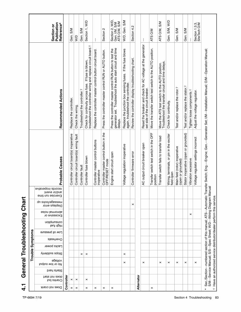
TP-66947/19
TP-6694 7/19 83Section 4 Troubleshooting
4.1
GeneralTroubleshootingChart
TroubleSym
ptoms
ProbableCauses
Recommended
Actions
Sectionor
Publication
Reference*
Doesnotcrank
Cranksbutdoesnotstart
Startshard
Noorlowoutputvoltage
Stopssuddenly
Lackspower
Overheats
Lowoilpressure
Highfuelconsumption
Excessiveorabnormalnoise
Displayserrormessage/locksup
Exerciseruntimeand/oreventrecordsinoperative
Controller
xx
Controllercircuitboard(s)inoperative
Replace
thecontroller.
Gen.S
/M
xx
Controllercircuitboard(s)wiring
fault
Check
thewiring.
W/D
xControllerfault
Troubleshootthe
controller.[
Gen.S
/M
xx
xControllerfuse
blow
nCheck
forcontinuityacross
fuse.Iffuse
isblow
n,troubleshootthecontrollerwiring
andreplacecircuitboard.[
Section1,W/D
xControllermastercontrolbuttons
inoperative
Replace
thecontrollermastercontrolbuttoncircuitboard.
—
xControllermastercontrolbuttoninthe
OFF/RESETmode
Press
thecontrollermastercontrolR
UNorAUTObutton.
Section2
xEnginestartcircuitopen
Press
thecontrollermastercontrolR
UNbuttontotestthe
generatorset.Troubleshootthe
autostartcircuitand
time
delays.
Section2,W/D,
Gen.I/M,S
/MATSO/M,S
/M
xx
Voltage
regulationinoperative
Replace
thejunctionboxsensingfuses.
Ifthefuse
blow
sagain,troubleshootthecontroller.
W/D,G
en.S
/M
xControllerfirmwareerror
Reviewthecontrollerdisplaytroubleshootingchart.
Section4.2
Alternator
xACoutputcircuitbreakeropen
ResetthebreakerandcheckforACvoltage
atthegenerator
setsideofthecircuitbreaker.
—
xTransfersw
itchtestsw
itchintheOFF
position
Movethetransfersw
itchtestsw
itchtotheAUTOposition.
ATSO/M
xTransfersw
itchfails
totransferload
MovetheATStestsw
itchtotheAUTOposition.
Troubleshootthe
transfercircuitand
timedelays.
ATSO/M,S
/M
xWiring,terminals,orpinintheexciter
fieldopen
Check
forcontinuity.
Gen.S
/M,W
/D
xMainfield(rotor)inoperative
(openorgrounded)
Testand/orreplacetherotor.[
Gen.S
/M
xStatorinoperative(openorgrounded)
Testand/orreplacethestator.[
Gen.S
/M
xVibrationexcessive
Tighten
loosecomponents.[
—
xVoltage
regulatorsettingsincorrect
Adjustthe
voltage
regulator.
Section1.3.3,
SiteTech
O/M
*Sec./S
ection—
numberedsectionofthismanual;ATS—Autom
aticTransferSwitch;Eng.—
Engine;Gen.—
GeneratorSet;I/M—InstallationManual;O/M—OperationManual;
S/M—Service
Manual;S/S—SpecSheet;W
/D—Wiring
Diagram
Manual
[Havean
authorized
servicedistributor/dealerperformthisservice.
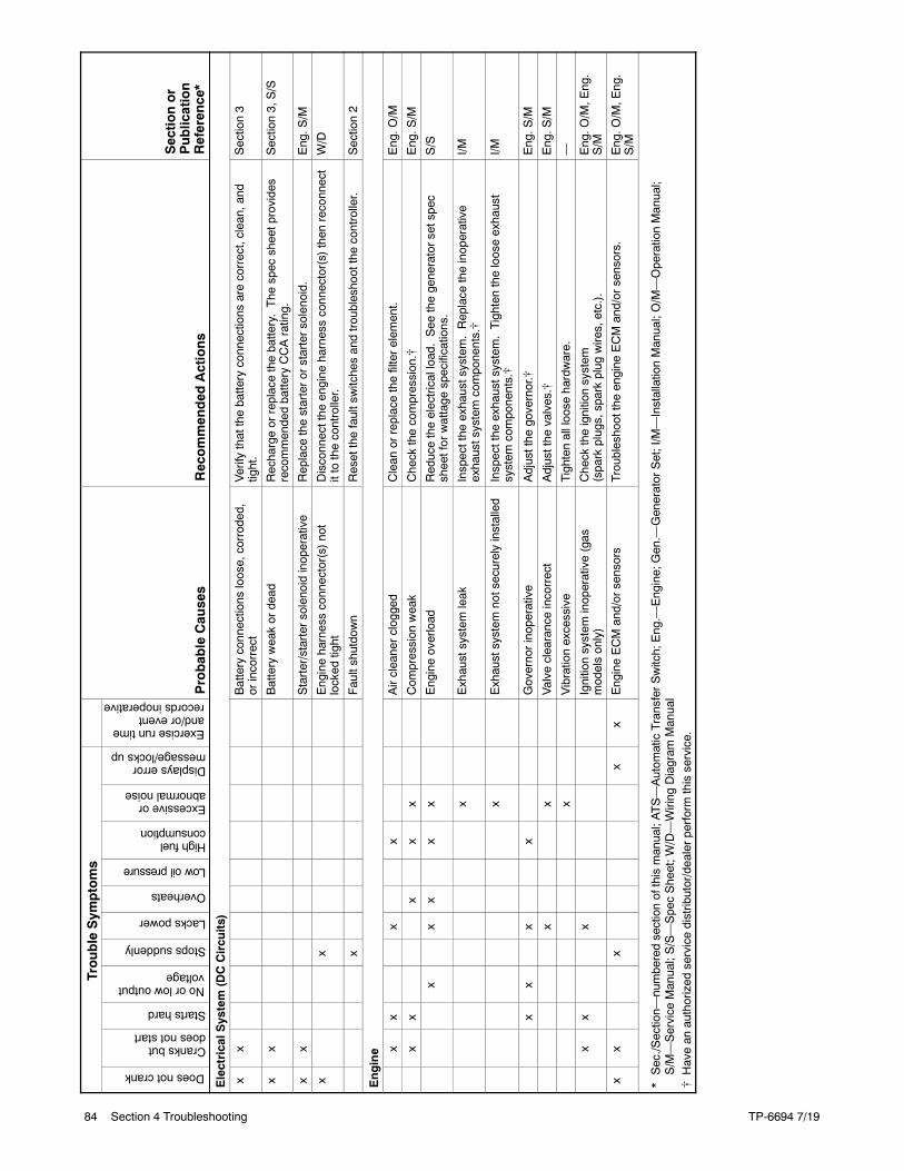
TP-6694 7/1984 Section 4 Troubleshooting
Sectionor
Publication
Reference*
Recommended
Actions
ProbableCauses
TroubleSym
ptoms
Sectionor
Publication
Reference*
Recommended
Actions
ProbableCauses
Exerciseruntimeand/oreventrecordsinoperative
Displayserrormessage/locksup
Excessiveorabnormalnoise
Highfuelconsumption
Lowoilpressure
Overheats
Lackspower
Stopssuddenly
Noorlowoutputvoltage
Startshard
Cranksbutdoesnotstart
Doesnotcrank
ElectricalS
ystem(DCCircuits)
xx
Batteryconnections
loose,corroded,
orincorrect
Verify
thatthebatteryconnections
arecorrect,clean,and
tight.
Section3
xx
Batteryweakordead
Rechargeorreplacethebattery.The
spec
sheetprovides
recommendedbatteryCCArating.
Section3,S/S
xx
Starter/startersolenoidinoperative
Replace
thestarterorstartersolenoid.
Eng.S
/M
xx
Engineharnessconnector(s)not
locked
tight
Disconnectthe
engine
harnessconnector(s)then
reconnect
ittothecontroller.
W/D
xFaultshutdown
Resetthefaultswitchesandtroubleshootthecontroller.
Section2
Engine x
xx
xAircleanerclogged
Clean
orreplacethefilterelem
ent.
Eng.O
/M
xx
xx
xCom
pression
weak
Check
thecompression.[
Eng.S
/M
xx
xx
xEngineoverload
Reducetheelectricalload.See
thegeneratorsetspec
sheetforwattage
specifications.
S/S
xExhaustsystem
leak
Inspectthe
exhaustsystem.Replace
theinoperative
exhaustsystemcomponents.[
I/M
xExhaustsystem
notsecurelyinstalled
Inspectthe
exhaustsystem.Tightenthelooseexhaust
system
components.[
I/M
xx
xx
Governorinoperative
Adjustthe
governor.[
Eng.S
/M
xx
Valve
clearanceincorrect
Adjustthe
valves.[
Eng.S
/M
xVibrationexcessive
Tighten
allloose
hardware.
—
xx
xIgnitionsystem
inoperative(gas
modelsonly)
Check
theignitionsystem
(sparkplugs,sparkplug
wires,etc.).
Eng.O
/M,E
ng.
S/M
xx
xx
xEngineECMand/orsensors
Troubleshootthe
engine
ECMand/orsensors.
Eng.O
/M,E
ng.
S/M
*Sec./S
ection—
numberedsectionofthismanual;ATS—Autom
aticTransferSwitch;Eng.—
Engine;Gen.—
GeneratorSet;I/M—InstallationManual;O/M—OperationManual;
S/M—Service
Manual;S/S—SpecSheet;W
/D—Wiring
Diagram
Manual
[Havean
authorized
servicedistributor/dealerperformthisservice.
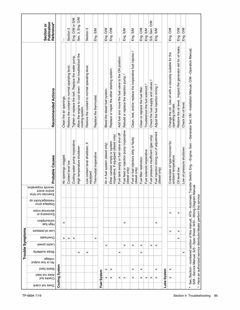
TP-66947/19
TP-6694 7/19 85Section 4 Troubleshooting
Sectionor
Publication
Reference*
Recommended
Actions
ProbableCauses
TroubleSym
ptoms
Sectionor
Publication
Reference*
Recommended
Actions
ProbableCauses
Exerciseruntimeand/oreventrecordsinoperative
Displayserrormessage/locksup
Excessiveorabnormalnoise
Highfuelconsumption
Lowoilpressure
Overheats
Lackspower
Stopssuddenly
Noorlowoutputvoltage
Startshard
Cranksbutdoesnotstart
Doesnotcrank
CoolingSystem
xx
Airopenings
clogged
Clean
theairopenings.
—
xCoolantlevellow
Restorethecoolanttonormaloperatinglevel.
Section3
xCoolingwaterpumpinoperative
Tighten
orreplacethebelt.Replace
thewaterpump.
Eng.O
/MorS/M
xHightemperatureshutdown
Allowtheengine
tocooldown.
Thentroubleshootthe
coolingsystem
.Sec.3,E
ng.O
/M
xLowcoolantlevelshutdown,if
equipped
Restorethecoolanttonormaloperatinglevel.
Section3
xThermostatinoperative
Replace
thethermostat.
Eng.S
/M
FuelSystem
xx
xAirinfuelsystem
(dieselonly)
Bleed
thedieselfuelsystem
.Eng.O
/M
xx
Ethercanisterem
ptyorsystem
inoperative,ifequipped
(dieselonly)
Replace
orrepairtheetherstartingsystem
.Eng.O
/M
xx
Fueltankem
ptyorfuelvalveshutoff
Add
fuelandmovethefuelvalvetotheONposition.
—
xx
xFuelfeedorinjectionpumpinoperative
(dieselonly)
Rebuildorreplacetheinjectionpump.[
Eng.S
/M
xx
xFuelorfuelinjectorsdirtyorfaulty
(dieselonly)
Clean,test,and/orreplacetheinoperativefuelinjector.[
Eng.S
/M
xx
xx
Fuelfilterrestriction
Clean
orreplacethefuelfilter.
Eng.O
/M
xFuelsolenoidinoperative
Troubleshootthe
fuelsolenoid.[
Eng.S
/M
xx
Fuelpressureinsufficient(gasonly)
Check
thefuelsupplyandvalves.[
S/S,G
en.O
/M
xx
xx
Fuelinjectiontim
ingoutofadjustment
(dieselonly)
Adjustthe
fuelinjectiontim
ing.[
Eng.S
/M
LubeSystem
xx
xx
Crankcase
oiltypeincorrectfor
ambienttem
perature
Changetheoil.Use
oilw
ithaviscosity
suitableforthe
operatingclimate.
Eng.O
/M
xx
xOillevellow
Restoretheoillevel.Inspectthe
generatorsetforoilleaks.
Eng.O
/M
xLowoilpressureshutdown
Check
theoillevel.
Eng.O
/M
*Sec./S
ection—
numberedsectionofthismanual;ATS—Autom
aticTransferSwitch;Eng.—
Engine;Gen.—
GeneratorSet;I/M—InstallationManual;O/M—OperationManual;
S/M—Service
Manual;S/S—SpecSheet;W
/D—Wiring
Diagram
Manual
[Havean
authorized
servicedistributor/dealerperformthisservice.
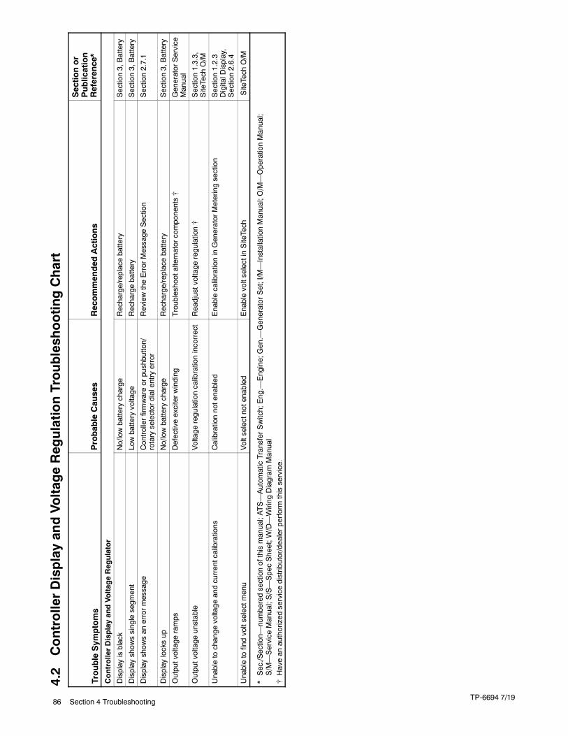
TP-6694 7/1986 Section 4 Troubleshooting
4.2
ControllerDisplayandVoltageRegulationTroubleshootingChart
TroubleSym
ptoms
ProbableCauses
Recommended
Actions
Sectionor
Publication
Reference*
ControllerDisplayandVoltageRegulator
Display
isblack
No/lowbatterycharge
Recharge/replacebattery
Section3,Battery
Display
show
ssinglesegm
ent
Lowbatteryvoltage
Rechargebattery
Section3,Battery
Display
show
san
errormessage
Controllerfirmwareorpushbutton/
rotaryselectordialentryerror
ReviewtheErrorMessage
Section
Section2.7.1
Display
locksup
No/lowbatterycharge
Recharge/replacebattery
Section3,Battery
Outputvoltage
ramps
Defectiveexciterwinding
Troubleshootalternatorcomponents[
GeneratorService
Manual
Outputvoltage
unstable
Voltage
regulationcalibrationincorrect
Readjustvoltage
regulation[
Section1.3.3,
SiteTech
O/M
Unabletochange
voltage
andcurrentcalibrations
Calibrationnotenabled
EnablecalibrationinGeneratorMeteringsection
Section1.2.3
DigitalD
isplay,
Section2.6.4
Unabletofindvoltselectmenu
Voltselectnotenabled
EnablevoltselectinSiteTech
SiteTech
O/M
*Sec./S
ection—
numberedsectionofthismanual;ATS—Autom
aticTransferSwitch;Eng.—
Engine;Gen.—
GeneratorSet;I/M—InstallationManual;O/M—OperationManual;
S/M—Service
Manual;S/S—SpecSheet;W
/D—Wiring
Diagram
Manual
[Havean
authorized
servicedistributor/dealerperformthisservice.

TP-6694 7/19 87
Notes
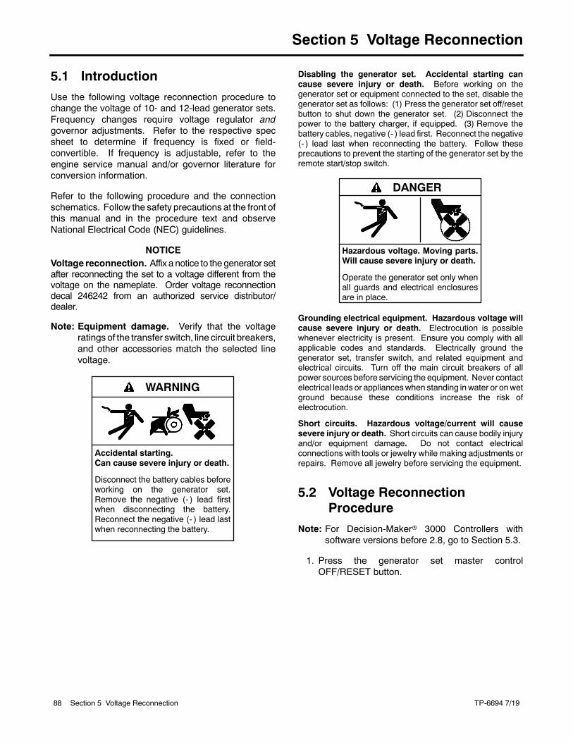
TP-6694 7/1988 Section 5 Voltage Reconnection
Section 5 Voltage Reconnection
5.1 Introduction
Use the following voltage reconnection procedure tochange the voltage of 10- and 12-lead generator sets.Frequency changes require voltage regulator andgovernor adjustments. Refer to the respective specsheet to determine if frequency is fixed or field-convertible. If frequency is adjustable, refer to theengine service manual and/or governor literature forconversion information.
Refer to the following procedure and the connectionschematics. Follow the safety precautions at the front ofthis manual and in the procedure text and observeNational Electrical Code (NEC) guidelines.
NOTICEVoltage reconnection. Affix a notice to thegenerator setafter reconnecting the set to a voltage different from thevoltage on the nameplate. Order voltage reconnectiondecal 246242 from an authorized service distributor/dealer.
Note: Equipment damage. Verify that the voltageratings of the transfer switch, line circuit breakers,and other accessories match the selected linevoltage.
Accidental starting.Can cause severe injury or death.
Disconnect the battery cables beforeworking on the generator set.Remove the negative (- ) lead firstwhen disconnecting the battery.Reconnect the negative (- ) lead lastwhen reconnecting the battery.
WARNING
Disabling the generator set. Accidental starting cancause severe injury or death. Before working on thegenerator set or equipment connected to the set, disable thegenerator set as follows: (1) Press the generator set off/resetbutton to shut down the generator set. (2) Disconnect thepower to the battery charger, if equipped. (3) Remove thebattery cables, negative (- ) lead first. Reconnect the negative(- ) lead last when reconnecting the battery. Follow theseprecautions to prevent the starting of the generator set by theremote start/stop switch.
Hazardous voltage. Moving parts.Will cause severe injury or death.
Operate the generator set only whenall guards and electrical enclosuresare in place.
DANGER
Grounding electrical equipment. Hazardous voltage willcause severe injury or death. Electrocution is possiblewhenever electricity is present. Ensure you comply with allapplicable codes and standards. Electrically ground thegenerator set, transfer switch, and related equipment andelectrical circuits. Turn off the main circuit breakers of allpower sources before servicing the equipment. Never contactelectrical leads or applianceswhen standing inwater or onwetground because these conditions increase the risk ofelectrocution.
Short circuits. Hazardous voltage/current will causesevere injury or death. Short circuits can cause bodily injuryand/or equipment damage. Do not contact electricalconnections with tools or jewelry while making adjustments orrepairs. Remove all jewelry before servicing the equipment.
5.2 Voltage ReconnectionProcedure
Note: For Decision-Makerr 3000 Controllers withsoftware versions before 2.8, go to Section 5.3.
1. Press the generator set master controlOFF/RESET button.
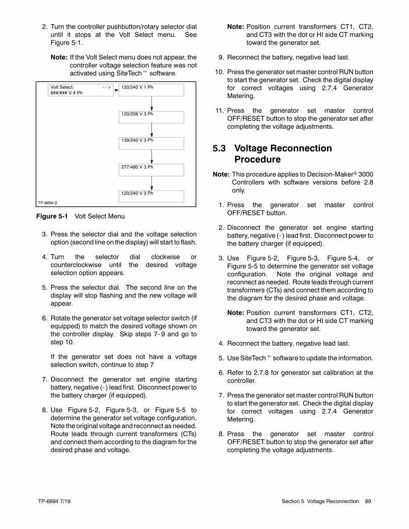
TP-6694 7/19 89Section 5 Voltage Reconnection
2. Turn the controller pushbutton/rotary selector dialuntil it stops at the Volt Select menu. SeeFigure 5-1.
Note: If the Volt Select menu does not appear, thecontroller voltage selection feature was notactivated using SiteTecht software.
Volt Select: - - >###/### V # Ph
139/240 V 3 Ph
120/240 V 1 Ph
120/208 V 3 Ph
120/240 V 3 Ph
277/480 V 3 Ph
TP-6694-2
Figure 5-1 Volt Select Menu
3. Press the selector dial and the voltage selectionoption (second line on the display) will start to flash.
4. Turn the selector dial clockwise orcounterclockwise until the desired voltageselection option appears.
5. Press the selector dial. The second line on thedisplay will stop flashing and the new voltage willappear.
6. Rotate the generator set voltage selector switch (ifequipped) to match the desired voltage shown onthe controller display. Skip steps 7- 9 and go tostep 10.
If the generator set does not have a voltageselection switch, continue to step 7
7. Disconnect the generator set engine startingbattery, negative (- ) lead first. Disconnect power tothe battery charger (if equipped).
8. Use Figure 5-2, Figure 5-3, or Figure 5-5 todetermine the generator set voltage configuration.Note the original voltage and reconnect as needed.Route leads through current transformers (CTs)and connect them according to the diagram for thedesired phase and voltage.
Note: Position current transformers CT1, CT2,and CT3 with the dot or HI side CT markingtoward the generator set.
9. Reconnect the battery, negative lead last.
10. Press the generator set master control RUN buttonto start the generator set. Check the digital displayfor correct voltages using 2.7.4 GeneratorMetering.
11. Press the generator set master controlOFF/RESET button to stop the generator set aftercompleting the voltage adjustments.
5.3 Voltage ReconnectionProcedure
Note: This procedure applies to Decision-Makerr 3000Controllers with software versions before 2.8only.
1. Press the generator set master controlOFF/RESET button.
2. Disconnect the generator set engine startingbattery, negative (- ) lead first. Disconnect power tothe battery charger (if equipped).
3. Use Figure 5-2, Figure 5-3, Figure 5-4, orFigure 5-5 to determine the generator set voltageconfiguration. Note the original voltage andreconnect as needed. Route leads through currenttransformers (CTs) and connect them according tothe diagram for the desired phase and voltage.
Note: Position current transformers CT1, CT2,and CT3 with the dot or HI side CT markingtoward the generator set.
4. Reconnect the battery, negative lead last.
5. Use SiteTecht software to update the information.
6. Refer to 2.7.8 for generator set calibration at thecontroller.
7. Press the generator set master control RUN buttonto start the generator set. Check the digital displayfor correct voltages using 2.7.4 GeneratorMetering.
8. Press the generator set master controlOFF/RESET button to stop the generator set aftercompleting the voltage adjustments.
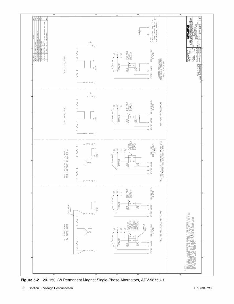
TP-6694 7/1990 Section 5 Voltage Reconnection
Figure 5-2 20- 150 kW Permanent Magnet Single-Phase Alternators, ADV-5875U-1
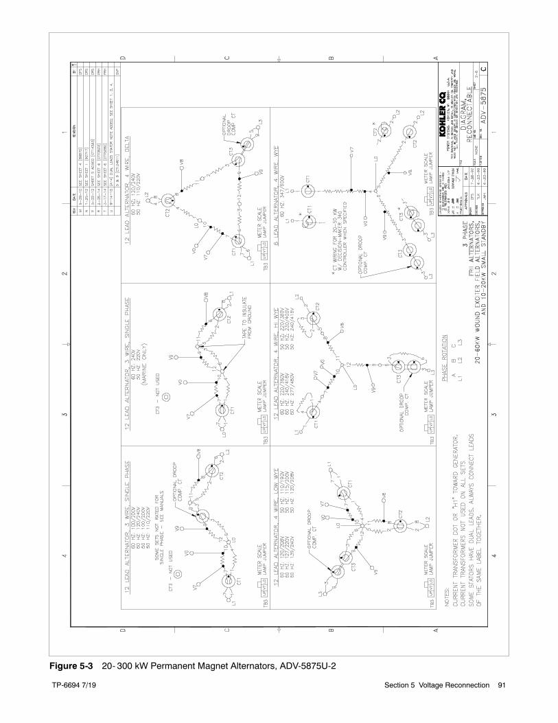
TP-6694 7/19 91Section 5 Voltage Reconnection
Figure 5-3 20- 300 kW Permanent Magnet Alternators, ADV-5875U-2
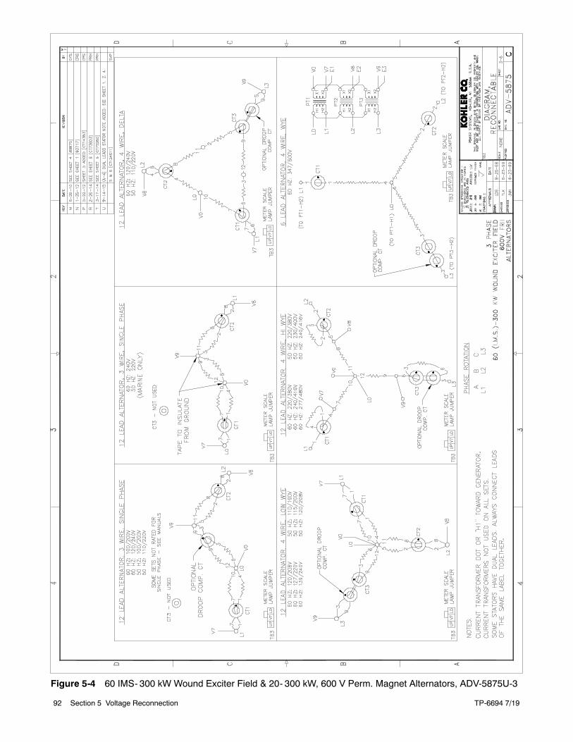
TP-6694 7/1992 Section 5 Voltage Reconnection
Figure 5-4 60 IMS- 300 kW Wound Exciter Field & 20- 300 kW, 600 V Perm. Magnet Alternators, ADV-5875U-3
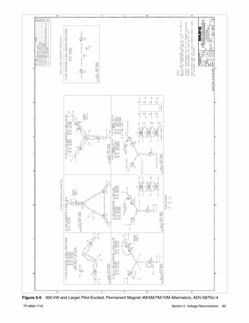
TP-6694 7/19 93Section 5 Voltage Reconnection
Figure 5-5 300 kW and Larger Pilot-Excited, Permanent Magnet 4M/5M/7M/10M Alternators, ADV-5875U-4
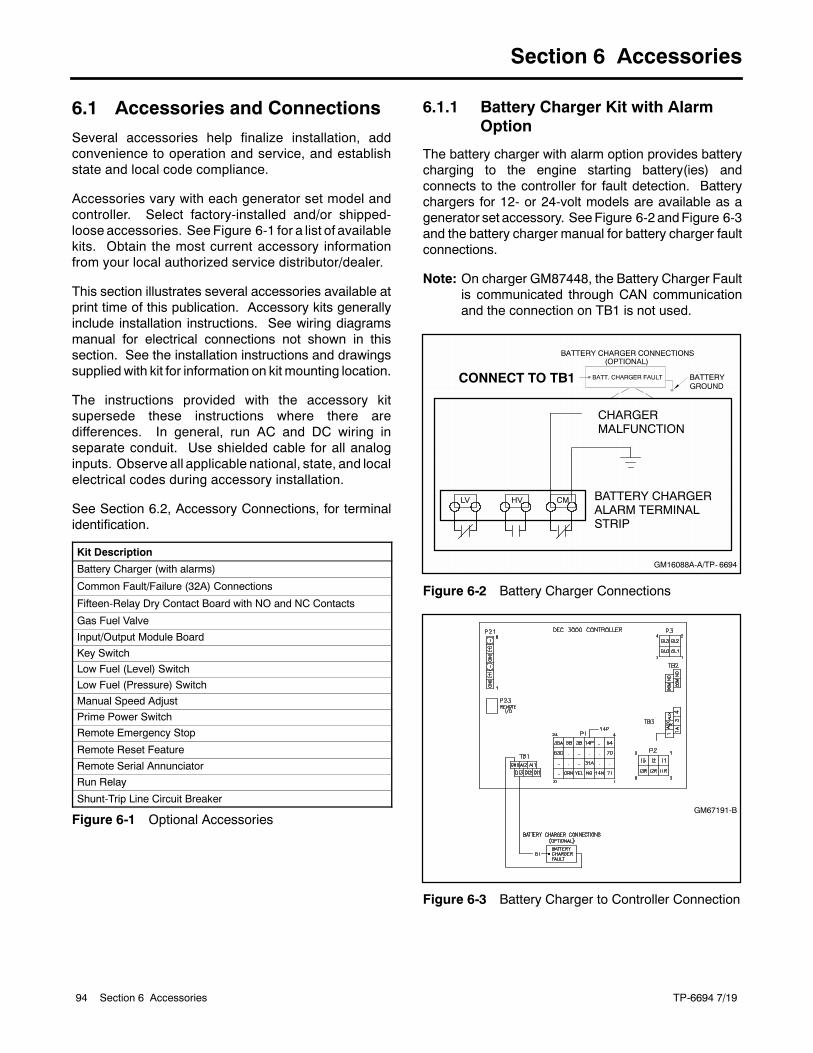
TP-6694 7/1994 Section 6 Accessories
Section 6 Accessories
6.1 Accessories and Connections
Several accessories help finalize installation, addconvenience to operation and service, and establishstate and local code compliance.
Accessories vary with each generator set model andcontroller. Select factory-installed and/or shipped-loose accessories. See Figure 6-1 for a list of availablekits. Obtain the most current accessory informationfrom your local authorized service distributor/dealer.
This section illustrates several accessories available atprint time of this publication. Accessory kits generallyinclude installation instructions. See wiring diagramsmanual for electrical connections not shown in thissection. See the installation instructions and drawingssupplied with kit for information on kit mounting location.
The instructions provided with the accessory kitsupersede these instructions where there aredifferences. In general, run AC and DC wiring inseparate conduit. Use shielded cable for all analoginputs. Observe all applicable national, state, and localelectrical codes during accessory installation.
See Section 6.2, Accessory Connections, for terminalidentification.
Kit Description
Battery Charger (with alarms)
Common Fault/Failure (32A) Connections
Fifteen-Relay Dry Contact Board with NO and NC Contacts
Gas Fuel Valve
Input/Output Module Board
Key Switch
Low Fuel (Level) Switch
Low Fuel (Pressure) Switch
Manual Speed Adjust
Prime Power Switch
Remote Emergency Stop
Remote Reset Feature
Remote Serial Annunciator
Run Relay
Shunt-Trip Line Circuit Breaker
Figure 6-1 Optional Accessories
6.1.1 Battery Charger Kit with AlarmOption
The battery charger with alarm option provides batterycharging to the engine starting battery(ies) andconnects to the controller for fault detection. Batterychargers for 12- or 24-volt models are available as agenerator set accessory. SeeFigure 6-2 andFigure 6-3and the battery charger manual for battery charger faultconnections.
Note: On charger GM87448, the Battery Charger Faultis communicated through CAN communicationand the connection on TB1 is not used.
GM16088A-A/TP- 6694
BATTERY CHARGERALARM TERMINALSTRIP
CHARGERMALFUNCTION
LV HV CM
CONNECT TO TB1
Figure 6-2 Battery Charger Connections
GM67191-B
Figure 6-3 Battery Charger to Controller Connection
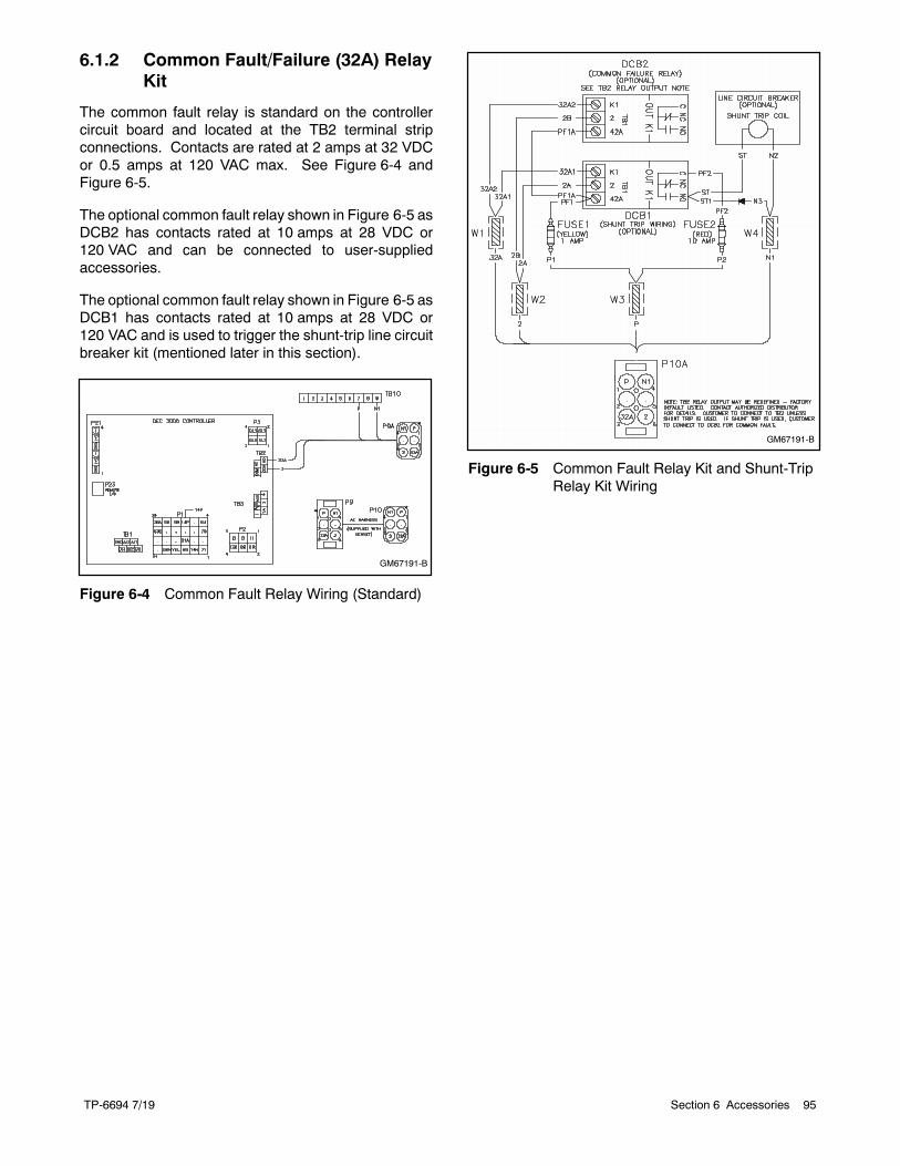
TP-6694 7/19 95Section 6 Accessories
6.1.2 Common Fault/Failure (32A) RelayKit
The common fault relay is standard on the controllercircuit board and located at the TB2 terminal stripconnections. Contacts are rated at 2 amps at 32 VDCor 0.5 amps at 120 VAC max. See Figure 6-4 andFigure 6-5.
The optional common fault relay shown in Figure 6-5 asDCB2 has contacts rated at 10 amps at 28 VDC or120 VAC and can be connected to user-suppliedaccessories.
The optional common fault relay shown in Figure 6-5 asDCB1 has contacts rated at 10 amps at 28 VDC or120 VAC and is used to trigger the shunt-trip line circuitbreaker kit (mentioned later in this section).
GM67191-B
Figure 6-4 Common Fault Relay Wiring (Standard)
GM67191-B
Figure 6-5 Common Fault Relay Kit and Shunt-TripRelay Kit Wiring
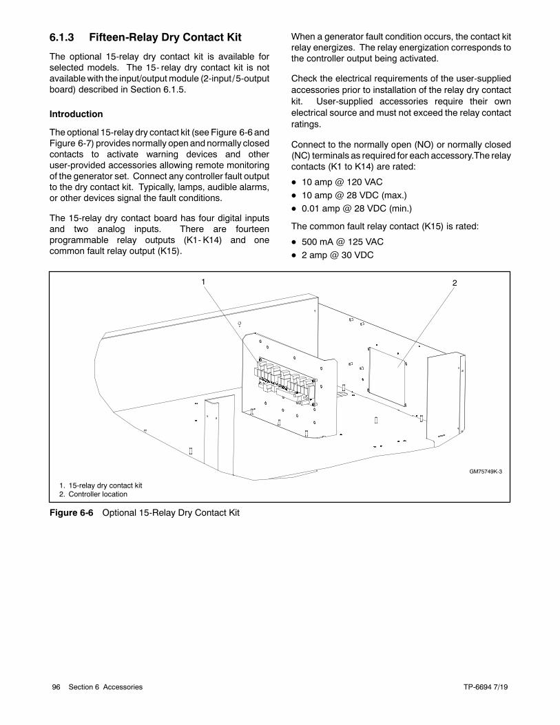
TP-6694 7/1996 Section 6 Accessories
6.1.3 Fifteen-Relay Dry Contact Kit
The optional 15-relay dry contact kit is available forselected models. The 15- relay dry contact kit is notavailablewith the input/outputmodule (2-input/5-outputboard) described in Section 6.1.5.
Introduction
The optional 15-relay dry contact kit (see Figure 6-6 andFigure 6-7) provides normally openandnormally closedcontacts to activate warning devices and otheruser-provided accessories allowing remote monitoringof the generator set. Connect any controller fault outputto the dry contact kit. Typically, lamps, audible alarms,or other devices signal the fault conditions.
The 15-relay dry contact board has four digital inputsand two analog inputs. There are fourteenprogrammable relay outputs (K1- K14) and onecommon fault relay output (K15).
When a generator fault condition occurs, the contact kitrelay energizes. The relay energization corresponds tothe controller output being activated.
Check the electrical requirements of the user-suppliedaccessories prior to installation of the relay dry contactkit. User-supplied accessories require their ownelectrical source and must not exceed the relay contactratings.
Connect to the normally open (NO) or normally closed(NC) terminals as required for each accessory.The relaycontacts (K1 to K14) are rated:
D 10 amp @ 120 VAC
D 10 amp @ 28 VDC (max.)D 0.01 amp @ 28 VDC (min.)
The common fault relay contact (K15) is rated:
D 500 mA @ 125 VAC
D 2 amp @ 30 VDC
1
GM75749K-3
1. 15-relay dry contact kit2. Controller location
2
Figure 6-6 Optional 15-Relay Dry Contact Kit
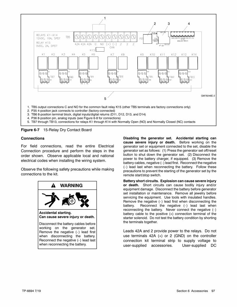
TP-6694 7/19 97Section 6 Accessories
GM78246E-2
1. TB5 output connections C and NO for the common fault relay K15 (other TB5 terminals are factory connections only)2. P35 4-position jack connects to controller (factory-connected)3. TB6 8-position terminal block, digital inputs/digital returns (D11, D12, D13, and D14)4. P36 8-position pin, analog inputs (see Figure 6-8 for connections)5. TB7 through TB13, connections for relays K1 through K14 with Normally Open (NO) and Normally Closed (NC) contacts
2 3 4
5
1
Figure 6-7 15-Relay Dry Contact Board
Connections
For field connections, read the entire ElectricalConnection procedure and perform the steps in theorder shown. Observe applicable local and nationalelectrical codes when installing the wiring system.
Observe the following safety precautions while makingconnections to the kit.
Accidental starting.Can cause severe injury or death.
Disconnect the battery cables beforeworking on the generator set.Remove the negative (- ) lead firstwhen disconnecting the battery.Reconnect the negative (- ) lead lastwhen reconnecting the battery.
WARNING
Disabling the generator set. Accidental starting cancause severe injury or death. Before working on thegenerator set or equipment connected to the set, disable thegenerator set as follows: (1) Press the generator set off/resetbutton to shut down the generator set. (2) Disconnect thepower to the battery charger, if equipped. (3) Remove thebattery cables, negative (- ) lead first. Reconnect the negative(- ) lead last when reconnecting the battery. Follow theseprecautions to prevent the starting of the generator set by theremote start/stop switch.
Battery short circuits. Explosion can cause severe injuryor death. Short circuits can cause bodily injury and/orequipment damage. Disconnect the battery before generatorset installation or maintenance. Remove all jewelry beforeservicing the equipment. Use tools with insulated handles.Remove the negative (- ) lead first when disconnecting thebattery. Reconnect the negative (- ) lead last whenreconnecting the battery. Never connect the negative (- )battery cable to the positive (+) connection terminal of thestarter solenoid. Do not test the battery condition by shortingthe terminals together.
Leads 42A and 2 provide power to the relays. Do notuse terminals 42A (+) or 2 (GND) on the controllerconnection kit terminal strip to supply voltage touser-supplied accessories. User-supplied DC
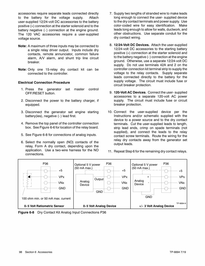
TP-6694 7/1998 Section 6 Accessories
accessories require separate leads connected directlyto the battery for the voltage supply. Attachuser-supplied 12/24-volt DC accessories to the batterypositive (+) connection at the starter solenoid and to thebattery negative (- ) connection at the engine ground.The 120 VAC accessories require a user-suppliedvoltage source.
Note: A maximum of three inputs may be connected toa single relay driver output. Inputs include drycontacts, remote annunciator, common failurealarm, A/V alarm, and shunt trip line circuitbreaker.
Note: Only one 15-relay dry contact kit can beconnected to the controller.
Electrical Connection Procedure
1. Press the generator set master controlOFF/RESET button.
2. Disconnect the power to the battery charger, ifequipped.
3. Disconnect the generator set engine startingbattery(ies), negative (- ) lead first.
4. Remove the top panel of the controller connectionbox. See Figure 6-6 for location of the relay board.
5. See Figure 6-8 for connections of analog inputs.
6. Select the normally open (NO) contacts of therelay, Form A dry contact, depending upon theapplication. Use a two-wire harness for the NOconnections.
7. Supply two lengths of stranded wire to make leadslong enough to connect the user- supplied deviceto the dry contact terminals and power supply. Usecolor-coded wire for easy identification. Makeleads long enough to allow for walls, ductwork, andother obstructions. Use separate conduit for thedry contact wiring.
8. 12/24-Volt DC Devices. Attach the user-supplied12/24-volt DC accessories to the starting batterypositive (+) connection at the starter solenoid andto the battery negative (- ) connection at the engineground. Otherwise, use a separate 12/24-volt DCsupply. Do not use terminals 42A and 2 on thecontroller connection kit terminal strip to supply thevoltage to the relay contacts. Supply separateleads connected directly to the battery for thesupply voltage. The circuit must include fuse orcircuit breaker protection.
9. 120-Volt AC Devices. Connect the user- suppliedaccessories to a separate 120-volt AC powersupply. The circuit must include fuse or circuitbreaker protection.
10. Connect the user-supplied device per theInstructions and/or schematic supplied with thedevice to a power source and to the dry contactterminals. Cut the user-supplied leads to length,strip lead ends, crimp on spade terminals (notsupplied), and connect the leads to the relaycontact screw terminals. Route the wiring for therelay dry contacts away from the generator setoutput leads.
11. Repeat Step 6 for the remaining dry contact relays.
TP-6694-6
+5
VPx
VNx
GND
P36
100 ohm min. or 50 mA max. current
+5
VPx
VNx
GND
P36
AnalogDevice
GND
Output
Optional 5 V power(50 mA max.)
+5
VPx
VNx
GND
P36
AnalogDevice
GND
Optional 5 V power(50 mA max.)
+
-
0- 5 Volt Ratiometric Sensor 0- 5 Volt Analog Device +/- 3 Volt Analog Device
Figure 6-8 Dry Contact Kit Analog Input Connections P36
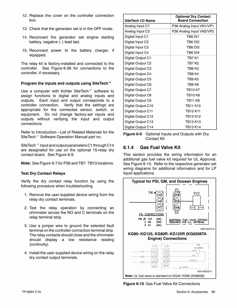
TP-6694 7/19 99Section 6 Accessories
12. Replace the cover on the controller connectionbox.
13. Check that the generator set is in the OFF mode.
14. Reconnect the generator set engine startingbattery, negative (- ) lead last.
15. Reconnect power to the battery charger, ifequipped.
The relay kit is factory-installed and connected to thecontroller. See Figure 6-36 for connections to thecontroller, if necessary.
Program the inputs and outputs using SiteTecht
Use a computer with Kohler SiteTecht software toassign functions to digital and analog inputs andoutputs. Each input and output corresponds to acontroller connection. Verify that the settings areappropriate for the connected sensor, switch, orequipment. Do not change factory-set inputs andoutputs without verifying the input and outputconnections.
Refer to Introduction—List of Related Materials for theSiteTecht Software Operation Manual part no.
SiteTecht input andoutput parametersC1 throughC14are designated for use on the optional 15-relay drycontact board. See Figure 6-9.
Note: See Figure 6-7 for P36 and TB7- TB13 locations.
Test Dry Contact Relays
Verify the dry contact relay function by using thefollowing procedure when troubleshooting.
1. Remove the user-supplied device wiring from therelay dry contact terminals.
2. Test the relay operation by connecting anohmmeter across the NO and C terminals on therelay terminal strip.
3. Use a jumper wire to ground the selected faultterminal on the controller connection terminal strip.The relay contacts should close and the ohmmetershould display a low resistance reading(continuity).
4. Install the user-supplied device wiring on the relaydry contact output terminals.
SiteTech I/O NameOptional Dry ContactBoard Connection
Analog Input C1 P36 Analog Input VN1/VP1
Analog Input C2 P36 Analog Input VN2/VP2
Digital Input C1 TB6 DI1
Digital Input C2 TB6 DI2
Digital Input C3 TB6 DI3
Digital Input C4 TB6 DI4
Digital Output C1 TB7 K1
Digital Output C2 TB7 K2
Digital Output C3 TB8 K3
Digital Output C4 TB8 K4
Digital Output C5 TB9 K5
Digital Output C6 TB9 K6
Digital Output C7 TB10 K7
Digital Output C8 TB10 K8
Digital Output C9 TB11 K9
Digital Output C10 TB11 K10
Digital Output C11 TB12 K11
Digital Output C12 TB12 K12
Digital Output C13 TB13 K13
Digital Output C14 TB13 K14
Figure 6-9 Optional Inputs and Outputs with DryContact Kit
6.1.4 Gas Fuel Valve KitThis section provides the wiring information for anadditional gas fuel valve kit required for UL Approval.See Figure 6-10. Refer to the respective generator setwiring diagrams for additional information and for LPliquid applications.
GM72401D-D
KG80-KG125, KG80R-KG125R (KG6208TAEngine) Connections
Typical for PSI, GM, and Doosan Engines
ADV-9052D-C
Note: UL fuel valve is standard on KG40- KG60 (KG6208).
FV3
(UL VALVE)
Figure 6-10 Gas Fuel Valve Kit Connections
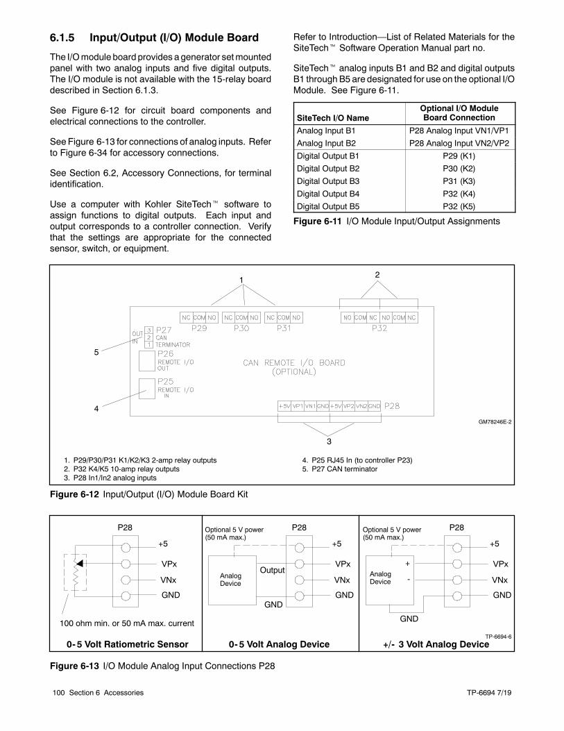
TP-6694 7/19100 Section 6 Accessories
6.1.5 Input/Output (I/O) Module Board
The I/Omodule board provides agenerator setmountedpanel with two analog inputs and five digital outputs.The I/O module is not available with the 15-relay boarddescribed in Section 6.1.3.
See Figure 6-12 for circuit board components andelectrical connections to the controller.
See Figure 6-13 for connections of analog inputs. Referto Figure 6-34 for accessory connections.
See Section 6.2, Accessory Connections, for terminalidentification.
Use a computer with Kohler SiteTecht software toassign functions to digital outputs. Each input andoutput corresponds to a controller connection. Verifythat the settings are appropriate for the connectedsensor, switch, or equipment.
Refer to Introduction—List of Related Materials for theSiteTecht Software Operation Manual part no.
SiteTecht analog inputs B1 and B2 and digital outputsB1 throughB5 are designated for use on the optional I/OModule. See Figure 6-11.
SiteTech I/O NameOptional I/O ModuleBoard Connection
Analog Input B1 P28 Analog Input VN1/VP1
Analog Input B2 P28 Analog Input VN2/VP2
Digital Output B1 P29 (K1)
Digital Output B2 P30 (K2)
Digital Output B3 P31 (K3)
Digital Output B4 P32 (K4)
Digital Output B5 P32 (K5)
Figure 6-11 I/O Module Input/Output Assignments
GM78246E-2
1. P29/P30/P31 K1/K2/K3 2-amp relay outputs2. P32 K4/K5 10-amp relay outputs3. P28 In1/In2 analog inputs
4. P25 RJ45 In (to controller P23)5. P27 CAN terminator
12
3
4
5
Figure 6-12 Input/Output (I/O) Module Board Kit
TP-6694-6
+5
VPx
VNx
GND
P28
100 ohm min. or 50 mA max. current
+5
VPx
VNx
GND
P28
AnalogDevice
GND
Output
Optional 5 V power(50 mA max.)
+5
VPx
VNx
GND
P28
AnalogDevice
GND
Optional 5 V power(50 mA max.)
+
-
0- 5 Volt Ratiometric Sensor 0- 5 Volt Analog Device +/- 3 Volt Analog Device
Figure 6-13 I/O Module Analog Input Connections P28
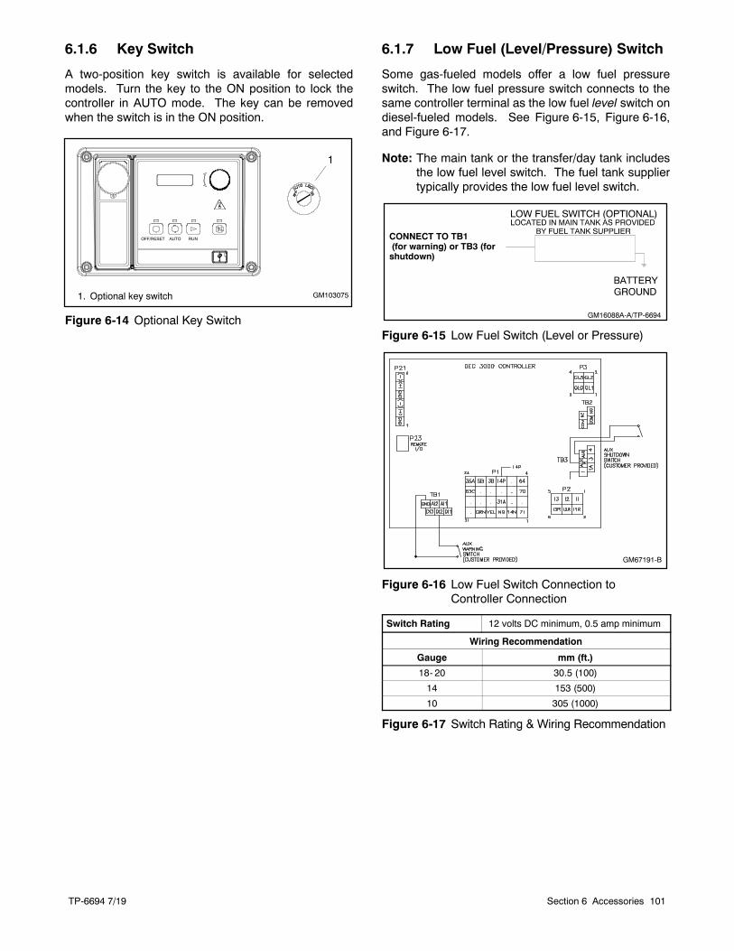
TP-6694 7/19 101Section 6 Accessories
6.1.6 Key Switch
A two-position key switch is available for selectedmodels. Turn the key to the ON position to lock thecontroller in AUTO mode. The key can be removedwhen the switch is in the ON position.
GM103075
OFF/RESET AUTO RUN
1
1. Optional key switch
Figure 6-14 Optional Key Switch
6.1.7 Low Fuel (Level/Pressure) Switch
Some gas-fueled models offer a low fuel pressureswitch. The low fuel pressure switch connects to thesame controller terminal as the low fuel level switch ondiesel-fueled models. See Figure 6-15, Figure 6-16,and Figure 6-17.
Note: The main tank or the transfer/day tank includesthe low fuel level switch. The fuel tank suppliertypically provides the low fuel level switch.
GM16088A-A/TP-6694
CONNECT TO TB1(for warning) or TB3 (forshutdown)
Figure 6-15 Low Fuel Switch (Level or Pressure)
GM67191-B
Figure 6-16 Low Fuel Switch Connection toController Connection
Switch Rating 12 volts DC minimum, 0.5 amp minimum
Wiring Recommendation
Gauge mm (ft.)
18- 20 30.5 (100)
14 153 (500)
10 305 (1000)
Figure 6-17 Switch Rating & Wiring Recommendation
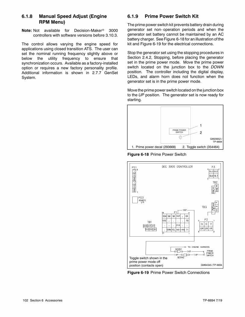
TP-6694 7/19102 Section 6 Accessories
6.1.8 Manual Speed Adjust (EngineRPM Menu)
Note: Not available for Decision-Makerr 3000controllers with software versions before 3.10.3.
The control allows varying the engine speed forapplications using closed transition ATS. The user canset the nominal running frequency slightly above orbelow the utility frequency to ensure thatsynchronization occurs. Available as a factory-installedoption or requires a new factory personality profile.Additional information is shown in 2.7.7 GenSetSystem.
6.1.9 Prime Power Switch Kit
The prime power switch kit prevents battery drain duringgenerator set non- operation periods and when thegenerator set battery cannot be maintained by an ACbattery charger. SeeFigure 6-18 for an illustration of thekit and Figure 6-19 for the electrical connections.
Stop the generator set using the stopping procedures inSection 2.4.2, Stopping, before placing the generatorset in the prime power mode. Move the prime powerswitch located on the junction box to the DOWNposition. The controller including the digital display,LEDs, and alarm horn does not function when thegenerator set is in the prime power mode.
Move theprimepower switch locatedon the junctionboxto the UP position. The generator set is now ready forstarting.
1. Prime power decal (293668)
PRIME POWERSWITCH
GM20652-/TP-6694
1
2
2. Toggle switch (354464)
Figure 6-18 Prime Power Switch
GM64345-/TP-6694
Toggle switch shown in theprime power mode offposition (contacts open)
Figure 6-19 Prime Power Switch Connections
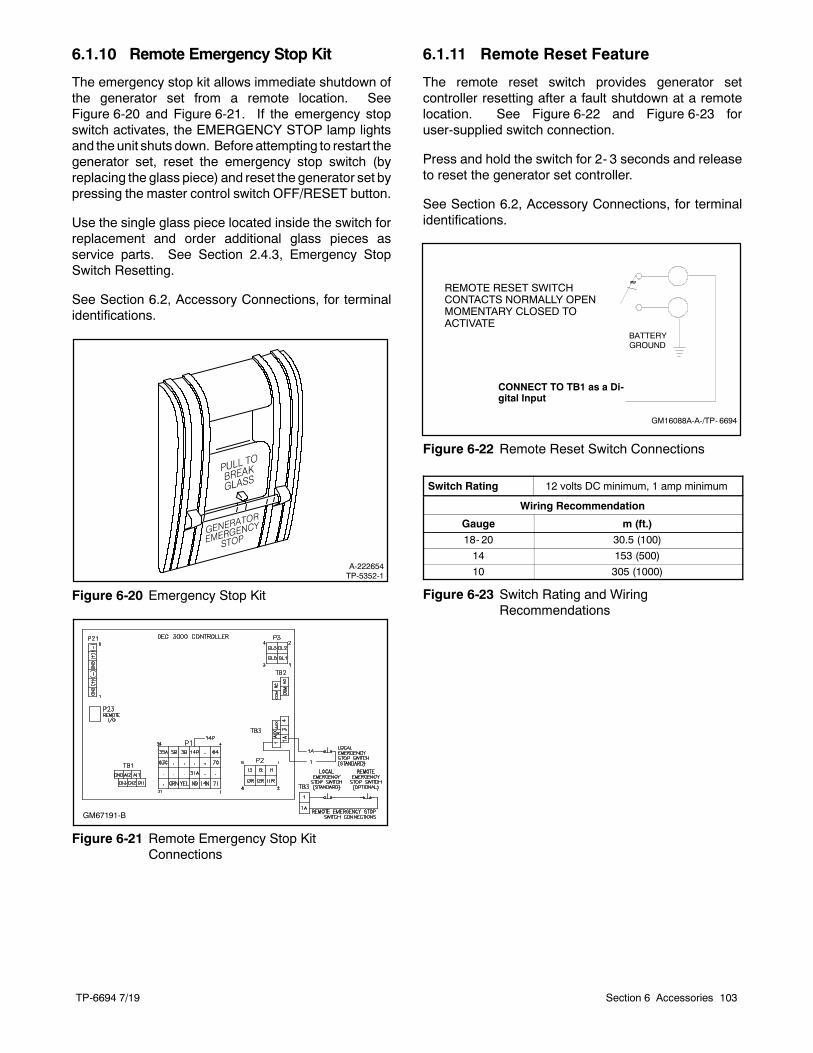
TP-6694 7/19 103Section 6 Accessories
6.1.10 Remote Emergency Stop Kit
The emergency stop kit allows immediate shutdown ofthe generator set from a remote location. SeeFigure 6-20 and Figure 6-21. If the emergency stopswitch activates, the EMERGENCY STOP lamp lightsand the unit shuts down. Before attempting to restart thegenerator set, reset the emergency stop switch (byreplacing the glass piece) and reset the generator set bypressing the master control switch OFF/RESET button.
Use the single glass piece located inside the switch forreplacement and order additional glass pieces asservice parts. See Section 2.4.3, Emergency StopSwitch Resetting.
See Section 6.2, Accessory Connections, for terminalidentifications.
A-222654TP-5352-1
Figure 6-20 Emergency Stop Kit
GM67191-B
Figure 6-21 Remote Emergency Stop KitConnections
6.1.11 Remote Reset Feature
The remote reset switch provides generator setcontroller resetting after a fault shutdown at a remotelocation. See Figure 6-22 and Figure 6-23 foruser-supplied switch connection.
Press and hold the switch for 2- 3 seconds and releaseto reset the generator set controller.
See Section 6.2, Accessory Connections, for terminalidentifications.
REMOTE RESET SWITCHCONTACTS NORMALLY OPENMOMENTARY CLOSED TOACTIVATE
GM16088A-A-/TP- 6694
CONNECT TO TB1 as a Di-gital Input
Figure 6-22 Remote Reset Switch Connections
Switch Rating 12 volts DC minimum, 1 amp minimum
Wiring Recommendation
Gauge m (ft.)
18- 20 30.5 (100)
14 153 (500)
10 305 (1000)
Figure 6-23 Switch Rating and WiringRecommendations
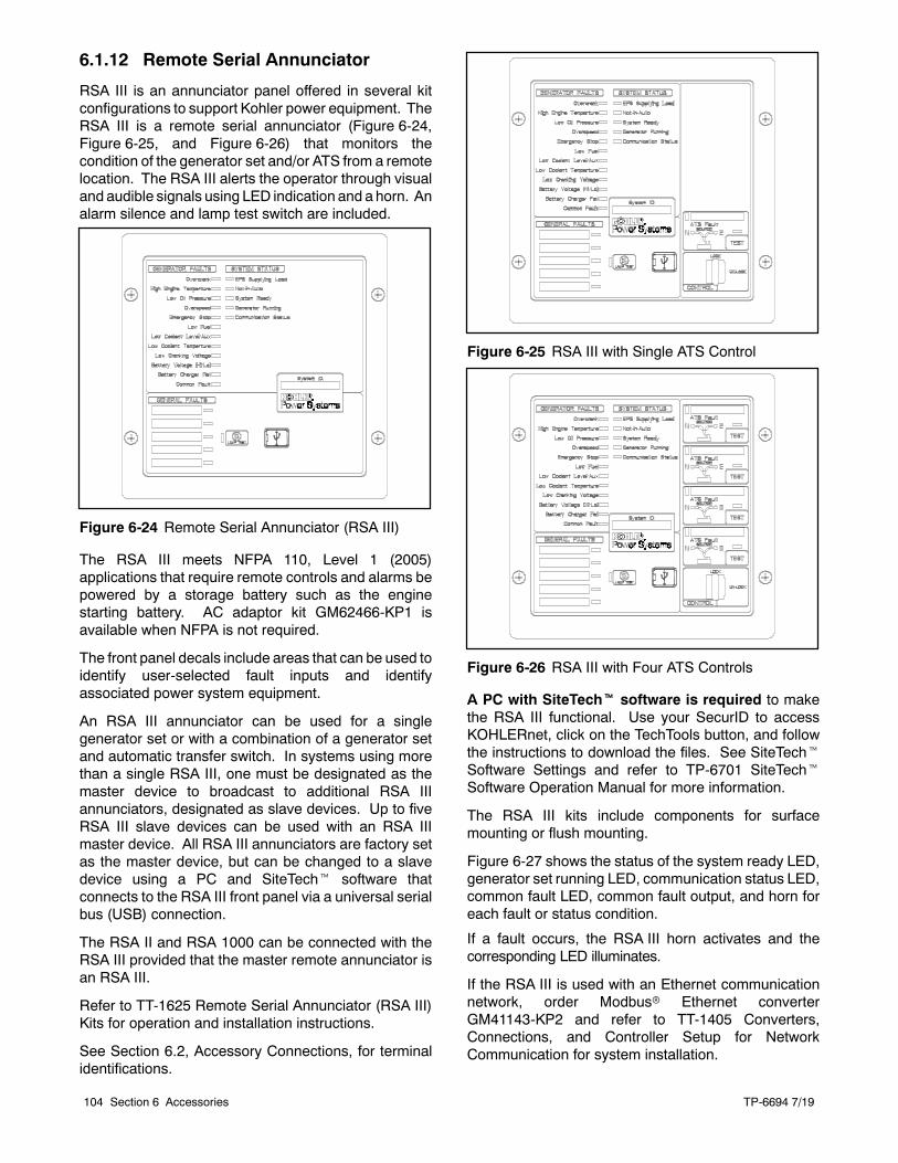
TP-6694 7/19104 Section 6 Accessories
6.1.12 Remote Serial Annunciator
RSA III is an annunciator panel offered in several kitconfigurations to support Kohler power equipment. TheRSA III is a remote serial annunciator (Figure 6-24,Figure 6-25, and Figure 6-26) that monitors thecondition of the generator set and/or ATS from a remotelocation. The RSA III alerts the operator through visualand audible signals using LED indication and a horn. Analarm silence and lamp test switch are included.
Figure 6-24 Remote Serial Annunciator (RSA III)
The RSA III meets NFPA 110, Level 1 (2005)applications that require remote controls and alarms bepowered by a storage battery such as the enginestarting battery. AC adaptor kit GM62466-KP1 isavailable when NFPA is not required.
The front panel decals include areas that can be used toidentify user-selected fault inputs and identifyassociated power system equipment.
An RSA III annunciator can be used for a singlegenerator set or with a combination of a generator setand automatic transfer switch. In systems using morethan a single RSA III, one must be designated as themaster device to broadcast to additional RSA IIIannunciators, designated as slave devices. Up to fiveRSA III slave devices can be used with an RSA IIImaster device. All RSA III annunciators are factory setas the master device, but can be changed to a slavedevice using a PC and SiteTecht software thatconnects to the RSA III front panel via a universal serialbus (USB) connection.
The RSA II and RSA 1000 can be connected with theRSA III provided that the master remote annunciator isan RSA III.
Refer to TT-1625 Remote Serial Annunciator (RSA III)Kits for operation and installation instructions.
See Section 6.2, Accessory Connections, for terminalidentifications.
Figure 6-25 RSA III with Single ATS Control
Figure 6-26 RSA III with Four ATS Controls
A PC with SiteTecht software is required to makethe RSA III functional. Use your SecurID to accessKOHLERnet, click on the TechTools button, and followthe instructions to download the files. See SiteTechtSoftware Settings and refer to TP-6701 SiteTechtSoftware Operation Manual for more information.
The RSA III kits include components for surfacemounting or flush mounting.
Figure 6-27 shows the status of the system ready LED,generator set running LED, communication status LED,common fault LED, common fault output, and horn foreach fault or status condition.
If a fault occurs, the RSA III horn activates and thecorresponding LED illuminates.
If the RSA III is used with an Ethernet communicationnetwork, order Modbusr Ethernet converterGM41143-KP2 and refer to TT-1405 Converters,Connections, and Controller Setup for NetworkCommunication for system installation.
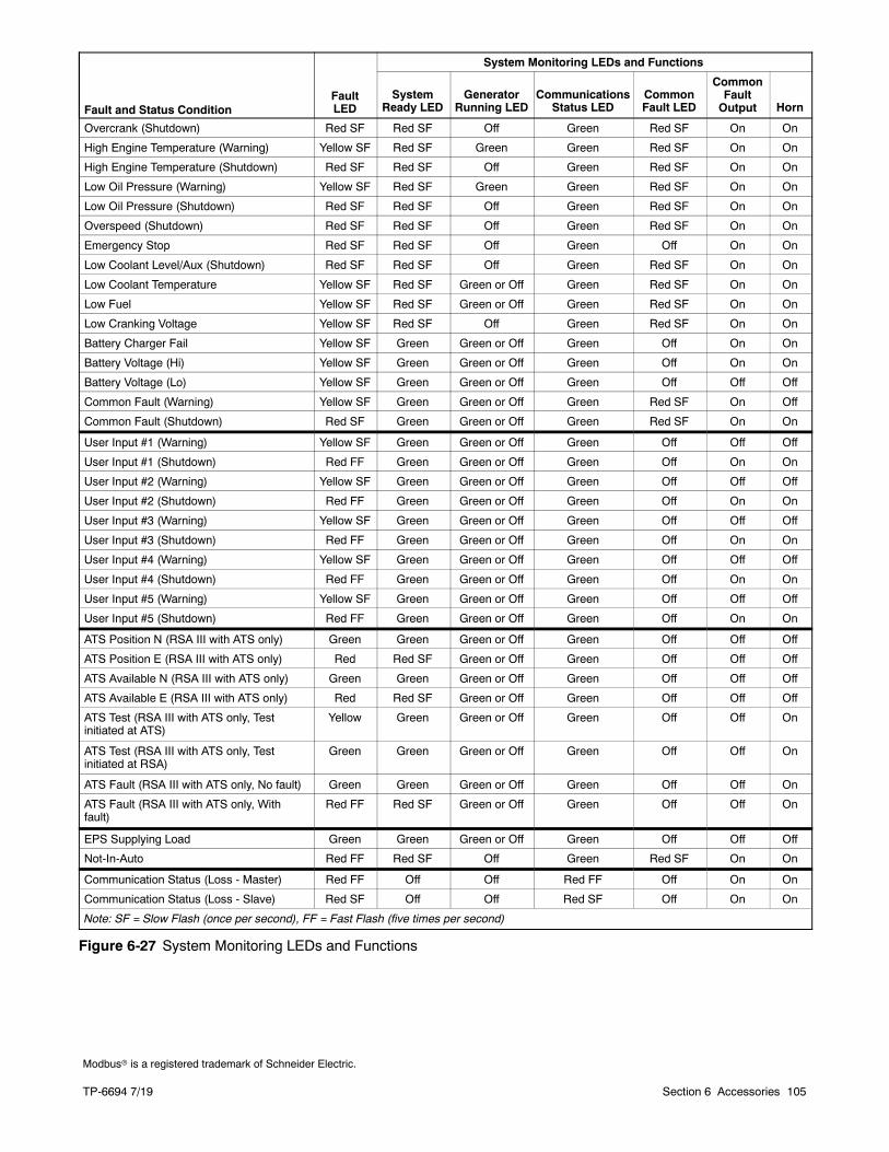
TP-6694 7/19 105Section 6 Accessories
Fault and Status ConditionFaultLED
System Monitoring LEDs and Functions
SystemReady LED
GeneratorRunning LED
CommunicationsStatus LED
CommonFault LED
CommonFaultOutput Horn
Overcrank (Shutdown) Red SF Red SF Off Green Red SF On On
High Engine Temperature (Warning) Yellow SF Red SF Green Green Red SF On On
High Engine Temperature (Shutdown) Red SF Red SF Off Green Red SF On On
Low Oil Pressure (Warning) Yellow SF Red SF Green Green Red SF On On
Low Oil Pressure (Shutdown) Red SF Red SF Off Green Red SF On On
Overspeed (Shutdown) Red SF Red SF Off Green Red SF On On
Emergency Stop Red SF Red SF Off Green Off On On
Low Coolant Level/Aux (Shutdown) Red SF Red SF Off Green Red SF On On
Low Coolant Temperature Yellow SF Red SF Green or Off Green Red SF On On
Low Fuel Yellow SF Red SF Green or Off Green Red SF On On
Low Cranking Voltage Yellow SF Red SF Off Green Red SF On On
Battery Charger Fail Yellow SF Green Green or Off Green Off On On
Battery Voltage (Hi) Yellow SF Green Green or Off Green Off On On
Battery Voltage (Lo) Yellow SF Green Green or Off Green Off Off Off
Common Fault (Warning) Yellow SF Green Green or Off Green Red SF On Off
Common Fault (Shutdown) Red SF Green Green or Off Green Red SF On On
User Input #1 (Warning) Yellow SF Green Green or Off Green Off Off Off
User Input #1 (Shutdown) Red FF Green Green or Off Green Off On On
User Input #2 (Warning) Yellow SF Green Green or Off Green Off Off Off
User Input #2 (Shutdown) Red FF Green Green or Off Green Off On On
User Input #3 (Warning) Yellow SF Green Green or Off Green Off Off Off
User Input #3 (Shutdown) Red FF Green Green or Off Green Off On On
User Input #4 (Warning) Yellow SF Green Green or Off Green Off Off Off
User Input #4 (Shutdown) Red FF Green Green or Off Green Off On On
User Input #5 (Warning) Yellow SF Green Green or Off Green Off Off Off
User Input #5 (Shutdown) Red FF Green Green or Off Green Off On On
ATS Position N (RSA III with ATS only) Green Green Green or Off Green Off Off Off
ATS Position E (RSA III with ATS only) Red Red SF Green or Off Green Off Off Off
ATS Available N (RSA III with ATS only) Green Green Green or Off Green Off Off Off
ATS Available E (RSA III with ATS only) Red Red SF Green or Off Green Off Off Off
ATS Test (RSA III with ATS only, Testinitiated at ATS)
Yellow Green Green or Off Green Off Off On
ATS Test (RSA III with ATS only, Testinitiated at RSA)
Green Green Green or Off Green Off Off On
ATS Fault (RSA III with ATS only, No fault) Green Green Green or Off Green Off Off On
ATS Fault (RSA III with ATS only, Withfault)
Red FF Red SF Green or Off Green Off Off On
EPS Supplying Load Green Green Green or Off Green Off Off Off
Not-In-Auto Red FF Red SF Off Green Red SF On On
Communication Status (Loss - Master) Red FF Off Off Red FF Off On On
Communication Status (Loss - Slave) Red SF Off Off Red SF Off On On
Note: SF = Slow Flash (once per second), FF = Fast Flash (five times per second)
Figure 6-27 System Monitoring LEDs and Functions
Modbusr is a registered trademark of Schneider Electric.
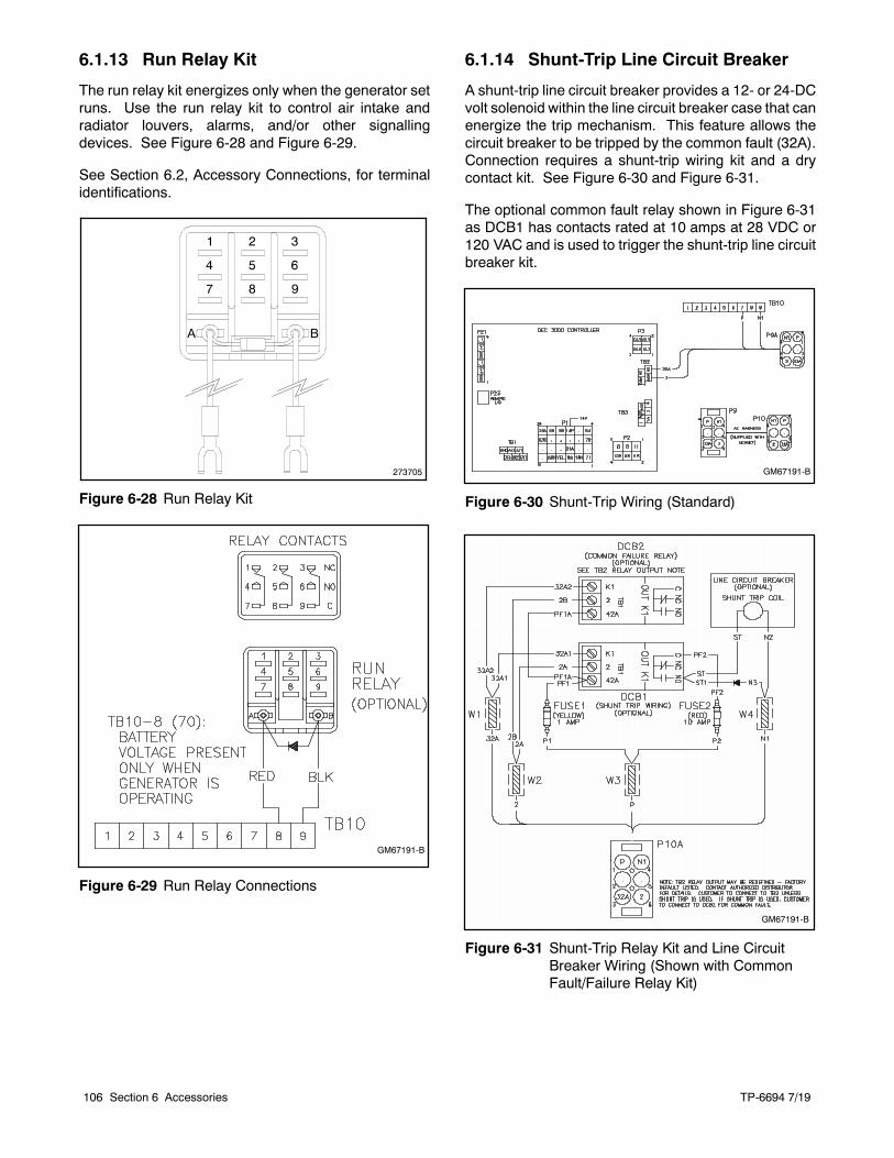
TP-6694 7/19106 Section 6 Accessories
6.1.13 Run Relay Kit
The run relay kit energizes only when the generator setruns. Use the run relay kit to control air intake andradiator louvers, alarms, and/or other signallingdevices. See Figure 6-28 and Figure 6-29.
See Section 6.2, Accessory Connections, for terminalidentifications.
273705
Figure 6-28 Run Relay Kit
GM67191-B
Figure 6-29 Run Relay Connections
6.1.14 Shunt-Trip Line Circuit Breaker
A shunt-trip line circuit breaker provides a 12- or 24-DCvolt solenoid within the line circuit breaker case that canenergize the trip mechanism. This feature allows thecircuit breaker to be tripped by the common fault (32A).Connection requires a shunt-trip wiring kit and a drycontact kit. See Figure 6-30 and Figure 6-31.
The optional common fault relay shown in Figure 6-31as DCB1 has contacts rated at 10 amps at 28 VDC or120 VAC and is used to trigger the shunt-trip line circuitbreaker kit.
GM67191-B
Figure 6-30 Shunt-Trip Wiring (Standard)
GM67191-B
Figure 6-31 Shunt-Trip Relay Kit and Line CircuitBreaker Wiring (Shown with CommonFault/Failure Relay Kit)
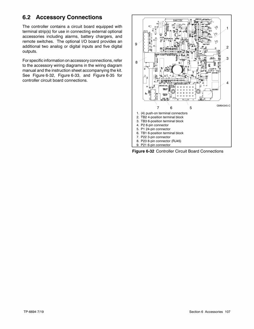
TP-6694 7/19 107Section 6 Accessories
6.2 Accessory Connections
The controller contains a circuit board equipped withterminal strip(s) for use in connecting external optionalaccessories including alarms, battery chargers, andremote switches. The optional I/O board provides anadditional two analog or digital inputs and five digitaloutputs.
For specific information on accessory connections, referto the accessory wiring diagrams in the wiring diagrammanual and the instruction sheet accompanying the kit.See Figure 6-32, Figure 6-33, and Figure 6-35 forcontroller circuit board connections.
1. (4) push-on terminal connectors2. TB2 4-position terminal block3. TB3 6-position terminal block4. P2 6-pin connector5. P1 24-pin connector6. TB1 6-position terminal block7. P22 3-pin connector8. P23 8-pin connector (RJ45)9. P21 6-pin connector
GM64345-C
1
2
3
4
56
9
7
8
Figure 6-32 Controller Circuit Board Connections
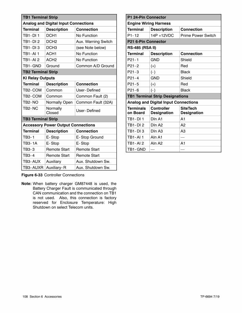
TP-6694 7/19108 Section 6 Accessories
TB1 Terminal Strip
Analog and Digital Input Connections
Terminal Description Connection
TB1- DI 1 DCH1 No Function
TB1- DI 2 DCH2 Aux. Warning Switch
TB1- DI 3 DCH3 (see Note below)
TB1- AI 1 ACH1 No Function
TB1- AI 2 ACH2 No Function
TB1-GND Ground Common A/D Ground
TB2 Terminal Strip
KI Relay Outputs
Terminal Description Connection
TB2- COM Common User- Defined
TB2- COM Common Common Fault (2)
TB2- NO Normally Open Common Fault (32A)
TB2- NC NormallyClosed User- Defined
TB3 Terminal Strip
Accessory Power Output Connections
Terminal Description Connection
TB3- 1 E- Stop E- Stop Ground
TB3- 1A E- Stop E- Stop
TB3- 3 Remote Start Remote Start
TB3- 4 Remote Start Remote Start
TB3- AUX Auxiliary Aux. Shutdown Sw.
TB3- AUXR Auxiliary- R Aux. Shutdown Sw.
P1 24-Pin Connector
Engine Wiring Harness
Terminal Description Connection
P1- 12 14P +12VDC Prime Power Switch
P21 6-Pin Connector
RS-485 (RSA II)
Terminal Description Connection
P21- 1 GND Shield
P21- 2 (+) Red
P21- 3 (- ) Black
P21- 4 GND Shield
P21- 5 (+) Red
P21- 6 (- ) Black
TB1 Terminal Strip Designations
Analog and Digital Input Connections
Terminalson Board
ControllerDesignation
SiteTechDesignation
TB1- DI 1 DIn A1 A1
TB1- DI 2 DIn A2 A2
TB1- DI 3 DIn A3 A3
TB1- AI 1 AIn A1 —
TB1- AI 2 AIn A2 A1
TB1-GND — —
Figure 6-33 Controller Connections
Note: When battery charger GM87448 is used, theBattery Charger Fault is communicated throughCAN communication and the connection on TB1is not used. Also, this connection is factoryreserved for Enclosure Temperature: HighShutdown on select Telecom units.
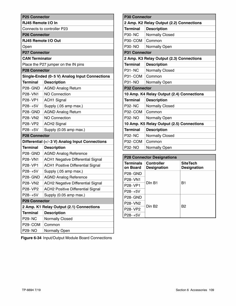
TP-6694 7/19 109Section 6 Accessories
P25 Connector
RJ45 Remote I/O In
Connects to controller P23
P26 Connector
RJ45 Remote I/O Out
Open
P27 Connector
CAN Terminator
Place the P27 jumper on the IN pins
P28 Connector
Single-Ended (0- 5 V) Analog Input Connections
Terminal Description
P28-GND AGND Analog Return
P28- VN1 NO Connection
P28- VP1 ACH1 Signal
P28- +5V Supply (.05 amp max.)
P28- GND AGND Analog Return
P28- VN2 NO Connection
P28- VP2 ACH2 Signal
P28- +5V Supply (0.05 amp max.)
P28 Connector
Differential (+/- 3 V) Analog Input Connections
Terminal Description
P28-GND AGND Analog Reference
P28- VN1 ACH1 Negative Differential Signal
P28- VP1 ACH1 Positive Differential Signal
P28- +5V Supply (.05 amp max.)
P28- GND AGND Analog Reference
P28- VN2 ACH2 Negative Differential Signal
P28- VP2 ACH2 Positive Differential Signal
P28- +5V Supply (0.05 amp max.)
P29 Connector
2 Amp. K1 Relay Output (2.1) Connections
Terminal Description
P29- NC Normally Closed
P29- COM Common
P29- NO Normally Open
P30 Connector
2 Amp. K2 Relay Output (2.2) Connections
Terminal Description
P30- NC Normally Closed
P30- COM Common
P30- NO Normally Open
P31 Connector
2 Amp. K3 Relay Output (2.3) Connections
Terminal Description
P31- NC Normally Closed
P31- COM Common
P31- NO Normally Open
P32 Connector
10 Amp. K4 Relay Output (2.4) Connections
Terminal Description
P32- NC Normally Closed
P32- COM Common
P32- NO Normally Open
10 Amp. K5 Relay Output (2.5) Connections
Terminal Description
P32- NC Normally Closed
P32- COM Common
P32- NO Normally Open
P28 Connector Designations
Terminalson Board
ControllerDesignation
SiteTechDesignation
P28-GND
DIn B1 B1P28- VN1
P28- VP1
P28- +5V
P28-GND
Din B2 B2P28- VN2
P28- VP2
P28- +5V
Figure 6-34 Input/Output Module Board Connections
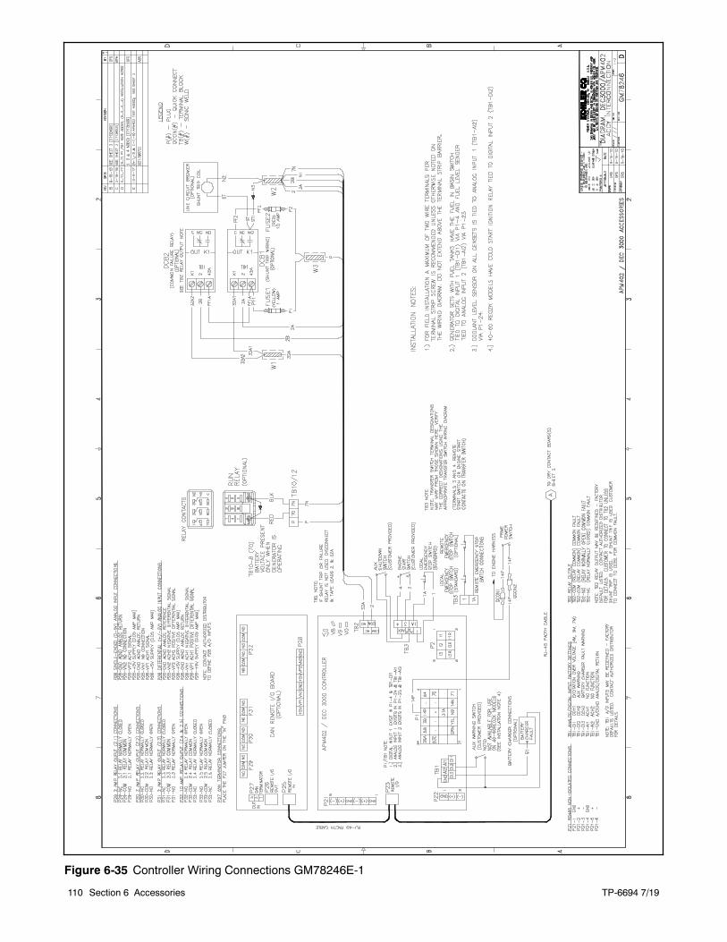
TP-6694 7/19110 Section 6 Accessories
Figure 6-35 Controller Wiring Connections GM78246E-1
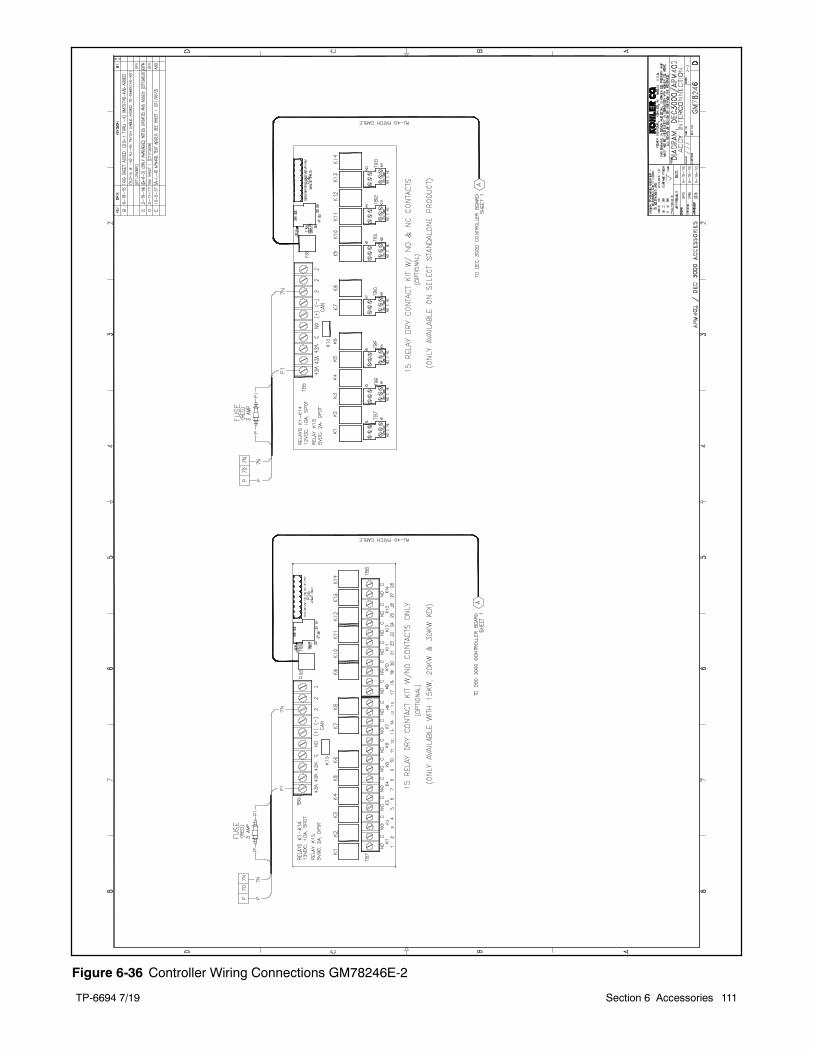
TP-6694 7/19 111Section 6 Accessories
Figure 6-36 Controller Wiring Connections GM78246E-2
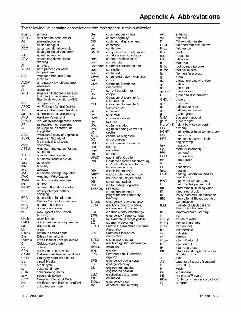
TP-6694 7/19112 Appendix
Appendix A Abbreviations
The following list contains abbreviations that may appear in this publication.
A, amp ampereABDC after bottom dead centerAC alternating currentA/D analog to digitalADC advanced digital control;
analog to digital converteradj. adjust, adjustmentADV advertising dimensional
drawingAh amp-hourAHWT anticipatory high water
temperatureAISI American Iron and Steel
InstituteALOP anticipatory low oil pressurealt. alternatorAl aluminumANSI American National Standards
Institute (formerly AmericanStandards Association, ASA)
AO anticipatory onlyAPDC Air Pollution Control DistrictAPI American Petroleum Instituteapprox. approximate, approximatelyAPU Auxiliary Power UnitAQMD Air Quality Management DistrictAR as required, as requestedAS as supplied, as stated, as
suggestedASE American Society of EngineersASME American Society of
Mechanical Engineersassy. assemblyASTM American Society for Testing
MaterialsATDC after top dead centerATS automatic transfer switchauto. automaticaux. auxiliaryavg. averageAVR automatic voltage regulatorAWG American Wire GaugeAWM appliance wiring materialbat. batteryBBDC before bottom dead centerBC battery charger, battery
chargingBCA battery charging alternatorBCI Battery Council InternationalBDC before dead centerBHP brake horsepowerblk. black (paint color), block
(engine)blk. htr. block heaterBMEP brake mean effective pressurebps bits per secondbr. brassBTDC before top dead centerBtu British thermal unitBtu/min. British thermal units per minuteC Celsius, centigradecal. calorieCAN controller area networkCARB California Air Resources BoardCAT5 Category 5 (network cable)CB circuit breakerCC crank cyclecc cubic centimeterCCA cold cranking ampsccw. counterclockwiseCEC Canadian Electrical Codecert. certificate, certification, certifiedcfh cubic feet per hour
cfm cubic feet per minuteCG center of gravityCID cubic inch displacementCL centerlinecm centimeterCMOS complementary metal oxide
substrate (semiconductor)com communications (port)coml commercialComl/Rec Commercial/Recreationalconn. connectioncont. continuedCPVC chlorinated polyvinyl chloridecrit. criticalCSA Canadian Standards
AssociationCT current transformerCu coppercUL Canadian Underwriter’s
LaboratoriesCUL Canadian Underwriter’s
Laboratoriescu. in. cubic inchcw. clockwiseCWC city water-cooledcyl. cylinderD/A digital to analogDAC digital to analog converterdB decibeldB(A) decibel (A weighted)DC direct currentDCR direct current resistancedeg., degreedept. departmentdia. diameterDI/EO dual inlet/end outletDIN Deutsches Institut fur Normung
e. V. (also Deutsche IndustrieNormenausschuss)
DIP dual inline packageDPDT double-pole, double-throwDPST double-pole, single-throwDS disconnect switchDVR digital voltage regulatorE2PROM, EEPROM
electrically-erasableprogrammable read-onlymemory
E, emer. emergency (power source)ECM electronic control module,
engine control moduleEDI electronic data interchangeEFR emergency frequency relaye.g. for example (exempli gratia)EG electronic governorEGSA Electrical Generating Systems
AssociationEIA Electronic Industries
AssociationEI/EO end inlet/end outletEMI electromagnetic interferenceemiss. emissioneng. engineEPA Environmental Protection
AgencyEPS emergency power systemER emergency relayES engineering special,
engineered specialESD electrostatic dischargeest. estimatedE-Stop emergency stopetc. et cetera (and so forth)
exh. exhaustext. externalF Fahrenheit, femaleFHM flat head machine (screw)fl. oz. fluid ounceflex. flexiblefreq. frequencyFS full scaleft. foot, feetft. lb. foot pounds (torque)ft./min. feet per minuteftp file transfer protocolg gramga. gauge (meters, wire size)gal. gallongen. generatorgenset generator setGFI ground fault interrupter
GND, groundgov. governorgph gallons per hourgpm gallons per minutegr. grade, grossGRD equipment groundgr. wt. gross weightH x W x D height by width by depthHC hex capHCHT high cylinder head temperatureHD heavy dutyHET high exhaust temp., high
engine temp.hex hexagonHg mercury (element)HH hex headHHC hex head capHP horsepowerhr. hourHS heat shrinkhsg. housingHVAC heating, ventilation, and air
conditioningHWT high water temperatureHz hertz (cycles per second)IBC International Building CodeIC integrated circuitID inside diameter, identificationIEC International Electrotechnical
CommissionIEEE Institute of Electrical and
Electronics EngineersIMS improved motor startingin. inchin. H2O inches of waterin. Hg inches of mercuryin. lb. inch poundsInc. incorporatedind. industrialint. internalint./ext. internal/externalI/O input/outputIP internet protocolISO International Organization for
StandardizationJ jouleJIS Japanese Industry Standardk kilo (1000)K kelvinkA kiloampereKB kilobyte (210 bytes)KBus Kohler communication protocolkg kilogram
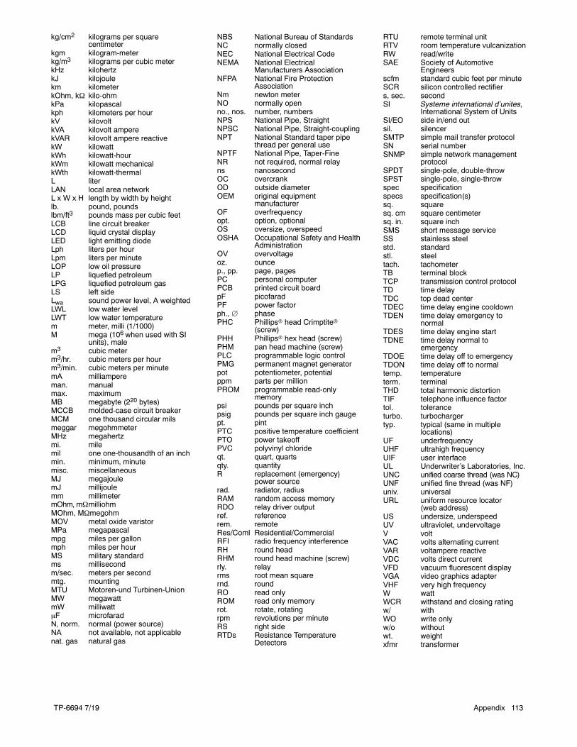
TP-6694 7/19 Appendix 113
kg/cm2 kilograms per squarecentimeter
kgm kilogram-meterkg/m3 kilograms per cubic meterkHz kilohertzkJ kilojoulekm kilometerkOhm, k kilo-ohmkPa kilopascalkph kilometers per hourkV kilovoltkVA kilovolt amperekVAR kilovolt ampere reactivekW kilowattkWh kilowatt-hourkWm kilowatt mechanicalkWth kilowatt-thermalL literLAN local area networkL x W x H length by width by heightlb. pound, poundslbm/ft3 pounds mass per cubic feetLCB line circuit breakerLCD liquid crystal displayLED light emitting diodeLph liters per hourLpm liters per minuteLOP low oil pressureLP liquefied petroleumLPG liquefied petroleum gasLS left sideLwa sound power level, A weightedLWL low water levelLWT low water temperaturem meter, milli (1/1000)M mega (106 when used with SI
units), malem3 cubic meterm3/hr. cubic meters per hourm3/min. cubic meters per minutemA milliampereman. manualmax. maximumMB megabyte (220 bytes)MCCB molded-case circuit breakerMCM one thousand circular milsmeggar megohmmeterMHz megahertzmi. milemil one one-thousandth of an inchmin. minimum, minutemisc. miscellaneousMJ megajoulemJ millijoulemm millimetermOhm, mmilliohmMOhm, MmegohmMOV metal oxide varistorMPa megapascalmpg miles per gallonmph miles per hourMS military standardms millisecondm/sec. meters per secondmtg. mountingMTU Motoren-und Turbinen-UnionMW megawattmW milliwattF microfaradN, norm. normal (power source)NA not available, not applicablenat. gas natural gas
NBS National Bureau of StandardsNC normally closedNEC National Electrical CodeNEMA National Electrical
Manufacturers AssociationNFPA National Fire Protection
AssociationNm newton meterNO normally openno., nos. number, numbersNPS National Pipe, StraightNPSC National Pipe, Straight-couplingNPT National Standard taper pipe
thread per general useNPTF National Pipe, Taper-FineNR not required, normal relayns nanosecondOC overcrankOD outside diameterOEM original equipment
manufacturerOF overfrequencyopt. option, optionalOS oversize, overspeedOSHA Occupational Safety and Health
AdministrationOV overvoltageoz. ouncep., pp. page, pagesPC personal computerPCB printed circuit boardpF picofaradPF power factorph., phasePHC Phillipsr head Crimptiter
(screw)PHH Phillipsr hex head (screw)PHM pan head machine (screw)PLC programmable logic controlPMG permanent magnet generatorpot potentiometer, potentialppm parts per millionPROM programmable read-only
memorypsi pounds per square inchpsig pounds per square inch gaugept. pintPTC positive temperature coefficientPTO power takeoffPVC polyvinyl chlorideqt. quart, quartsqty. quantityR replacement (emergency)
power sourcerad. radiator, radiusRAM random access memoryRDO relay driver outputref. referencerem. remoteRes/Coml Residential/CommercialRFI radio frequency interferenceRH round headRHM round head machine (screw)rly. relayrms root mean squarernd. roundRO read onlyROM read only memoryrot. rotate, rotatingrpm revolutions per minuteRS right sideRTDs Resistance Temperature
Detectors
RTU remote terminal unitRTV room temperature vulcanizationRW read/writeSAE Society of Automotive
Engineersscfm standard cubic feet per minuteSCR silicon controlled rectifiers, sec. secondSI Systeme international d’unites,
International System of UnitsSI/EO side in/end outsil. silencerSMTP simple mail transfer protocolSN serial numberSNMP simple network management
protocolSPDT single-pole, double-throwSPST single-pole, single-throwspec specificationspecs specification(s)sq. squaresq. cm square centimetersq. in. square inchSMS short message serviceSS stainless steelstd. standardstl. steeltach. tachometerTB terminal blockTCP transmission control protocolTD time delayTDC top dead centerTDEC time delay engine cooldownTDEN time delay emergency to
normalTDES time delay engine startTDNE time delay normal to
emergencyTDOE time delay off to emergencyTDON time delay off to normaltemp. temperatureterm. terminalTHD total harmonic distortionTIF telephone influence factortol. toleranceturbo. turbochargertyp. typical (same in multiple
locations)UF underfrequencyUHF ultrahigh frequencyUIF user interfaceUL Underwriter’s Laboratories, Inc.UNC unified coarse thread (was NC)UNF unified fine thread (was NF)univ. universalURL uniform resource locator
(web address)US undersize, underspeedUV ultraviolet, undervoltageV voltVAC volts alternating currentVAR voltampere reactiveVDC volts direct currentVFD vacuum fluorescent displayVGA video graphics adapterVHF very high frequencyW wattWCR withstand and closing ratingw/ withWO write onlyw/o withoutwt. weightxfmr transformer
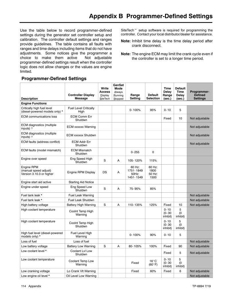
TP-6694 7/19114 Appendix
Appendix B Programmer-Defined Settings
Use the table below to record programmer-definedsettings during the generator set controller setup andcalibration. The controller default settings and rangesprovide guidelines. The table contains all faults withranges and time delays including items that do not haveadjustments. Some notices give the programmer achoice to make them active Not adjustableprogrammer-defined settings result when the controllerlogic does not allow changes or the values are enginelimited.
SiteTecht setup software is required for programming thecontroller. Contact your local distributor/dealer for assistance.
Note: Inhibit time delay is the time delay period aftercrank disconnect.
Note: The engine ECMmay limit the crank cycle even ifthe controller is set to a longer time period.
Programmer-Defined Settings
DescriptionController Display
Message
WriteAccessDisplaySiteTech
GenSetModeAlwaysRunningStopped
RangeSetting
DefaultSelection
TimeDelayRange(sec.)
DefaultTimeDelay(sec.)
Programmer-DefinedSettings
Engine Functions
Critically high fuel level(diesel-powered models only) *
Fuel Level CriticallyHigh 0- 100% 95% 0- 10 5
ECM communications loss ECM Comm ErrShutdwn Fixed 10 Not adjustable
ECM diagnostics (multipleinputs) [ ECM xxxxxx Warning Not adjustable
ECM diagnostics (multipleinputs) [ ECM xxxxxx Shutdwn Not adjustable
ECM faults (address conflict) ECM Addr ErrShutdwn Not adjustable
ECM faults (model mismatch) ECM MismatchShutdwn 0- 255 0
Engine over speed Eng Speed HighShutdwn S A 105- 120% 115%
Engine RPM(manual speed adjust)Version 3.10.3 or higher Engine RPM Display DS A
60 Hz:1751- 184950Hz:
1451- 1549
60 Hz:180050 Hz:1500
Engine start aid active Starting Aid Notice
Engine under speed Eng Speed LowShutdwn S A 75- 95% 85%
Fuel tank leak * Fuel Leak Warning Not adjustable
Fuel tank leak * Fuel Leak Shutdwn Not adjustable
High battery voltage Battery High Warning S A 110- 135% 125% Fixed 10 Not adjustable
High coolant temperature Coolnt Temp HighWarning
0- 10(0- 30inhibit)
5(0
inhibit)
High coolant temperature Coolnt Temp HighShutdwn
0- 10(0- 30inhibit)
5(0
inhibit)
High fuel level (diesel-poweredmodels only) *
Fuel Level HighWarning 0- 100% 90% 0- 10 5
Loss of fuel Loss of fuel Not adjustable
Low battery voltage Battery Low Warning S A 80- 105% 100% Fixed 90 Not adjustable
Low coolant level * Coolant Lvl LowShutdwn Fixed 5 Not adjustable
Low coolant temperature Coolant Temp LowWarning Fixed 16_C
(60_F)
0- 10(0- 30inhibit)
5(0
inhibit)
Low cranking voltage Lo Crank Vlt Warning Fixed 60% Fixed 6 Not adjustable
Low engine oil level * Oil Level Low Warning Not adjustable
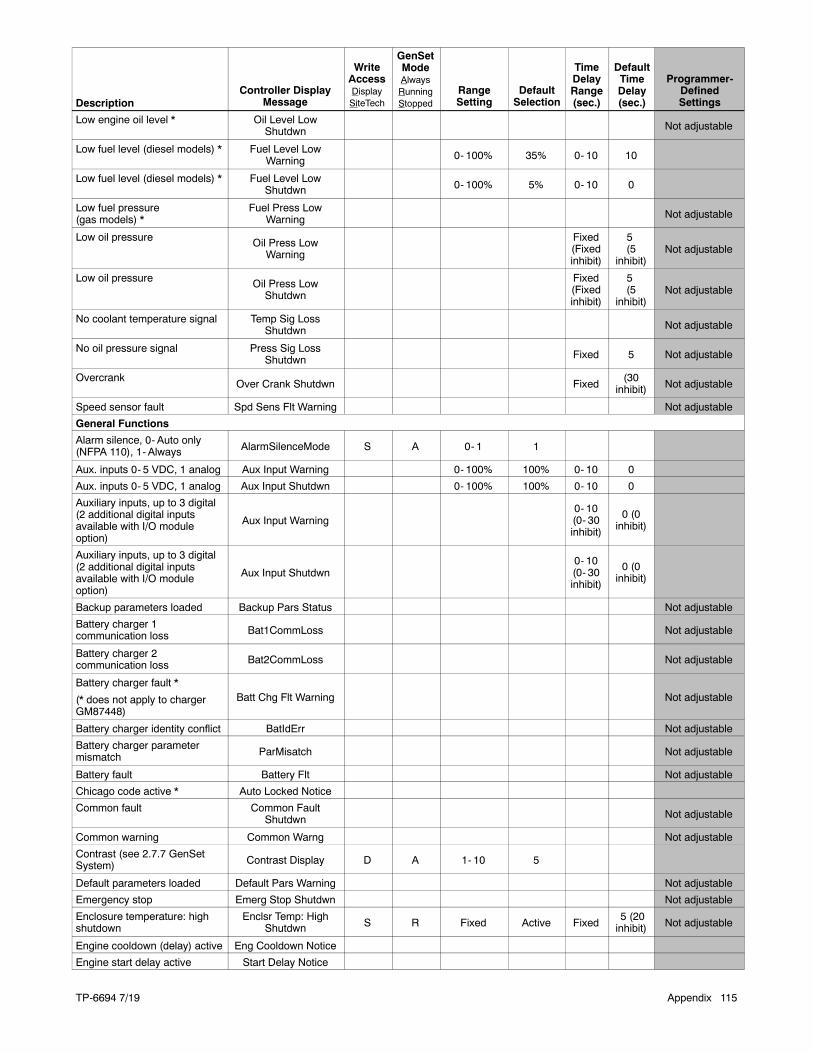
TP-6694 7/19 Appendix 115
Description
Programmer-DefinedSettings
DefaultTimeDelay(sec.)
TimeDelayRange(sec.)
DefaultSelection
RangeSetting
GenSetModeAlwaysRunningStopped
WriteAccessDisplaySiteTech
Controller DisplayMessage
Low engine oil level * Oil Level LowShutdwn Not adjustable
Low fuel level (diesel models) * Fuel Level LowWarning 0- 100% 35% 0- 10 10
Low fuel level (diesel models) * Fuel Level LowShutdwn 0- 100% 5% 0- 10 0
Low fuel pressure(gas models) *
Fuel Press LowWarning Not adjustable
Low oil pressure Oil Press LowWarning
Fixed(Fixedinhibit)
5(5
inhibit)Not adjustable
Low oil pressure Oil Press LowShutdwn
Fixed(Fixedinhibit)
5(5
inhibit)Not adjustable
No coolant temperature signal Temp Sig LossShutdwn Not adjustable
No oil pressure signal Press Sig LossShutdwn Fixed 5 Not adjustable
OvercrankOver Crank Shutdwn Fixed
(30inhibit) Not adjustable
Speed sensor fault Spd Sens Flt Warning Not adjustable
General Functions
Alarm silence, 0- Auto only(NFPA 110), 1- Always AlarmSilenceMode S A 0- 1 1
Aux. inputs 0- 5 VDC, 1 analog Aux Input Warning 0- 100% 100% 0- 10 0
Aux. inputs 0- 5 VDC, 1 analog Aux Input Shutdwn 0- 100% 100% 0- 10 0
Auxiliary inputs, up to 3 digital(2 additional digital inputsavailable with I/O moduleoption)
Aux Input Warning0- 10(0- 30inhibit)
0 (0inhibit)
Auxiliary inputs, up to 3 digital(2 additional digital inputsavailable with I/O moduleoption)
Aux Input Shutdwn0- 10(0- 30inhibit)
0 (0inhibit)
Backup parameters loaded Backup Pars Status Not adjustable
Battery charger 1communication loss Bat1CommLoss Not adjustable
Battery charger 2communication loss Bat2CommLoss Not adjustable
Battery charger fault *
(* does not apply to chargerGM87448)
Batt Chg Flt Warning Not adjustable
Battery charger identity conflict BatIdErr Not adjustable
Battery charger parametermismatch ParMisatch Not adjustable
Battery fault Battery Flt Not adjustable
Chicago code active * Auto Locked Notice
Common fault Common FaultShutdwn Not adjustable
Common warning Common Warng Not adjustable
Contrast (see 2.7.7 GenSetSystem) Contrast Display D A 1- 10 5
Default parameters loaded Default Pars Warning Not adjustable
Emergency stop Emerg Stop Shutdwn Not adjustable
Enclosure temperature: highshutdown
Enclsr Temp: HighShutdwn S R Fixed Active Fixed
5 (20inhibit) Not adjustable
Engine cooldown (delay) active Eng Cooldown Notice
Engine start delay active Start Delay Notice

TP-6694 7/19116 Appendix
Description
Programmer-DefinedSettings
DefaultTimeDelay(sec.)
TimeDelayRange(sec.)
DefaultSelection
RangeSetting
GenSetModeAlwaysRunningStopped
WriteAccessDisplaySiteTech
Controller DisplayMessage
Engine started Engine Start Status Not adjustable
Engine stopped Engine Stop Status Not adjustable
EPS supplying load Emerg Pwr On Notice Not adjustable
File system error (controllerfault) File Error Shutdwn Not adjustable
Generator running Gen Running Notice Not adjustable
Input/output (optional moduleboard) communication loss OB1 Com Loss Not adjustable
Internal failure Intern Error Shutdwn Not adjustable
Measurement Units,0- English, 1-Metric Measurement Display DS A 0- 1 1
Metering communication loss MeterCommLosShutdwn Not adjustable
NFPA 110 alarm active NFPA Alarm Notice
Not in auto (master controlbuttons) Not In Auto Warning Not adjustable
Prime power application,0- Standby, 1- Prime Power Type DS A 0- 1 0
Remote start Remote Start Status Not adjustable
System ready System Ready Status Not adjustable
System timer failed Timer Error Notice Not adjustable
Generator Functions
AC sensing loss AC Sens LossWarning Not adjustable
AC sensing loss AC Sens LossShutdwn Fixed 3 Not adjustable
Alternator protection Alt Protect Shutdwn Not adjustable
Ground fault input * Ground Fault Warning Not adjustable
kW overloadTotal Power High
Shutdwn Fixed
102%standby,112%prime
Fixed 60 Not adjustable
Locked rotor (failed to crank) Locked RotorShutdwn S A 1- 5 5
Overfrequency Freq High Shutdwn 102- 140% 110% Fixed 10 Not adjustable
Overvoltage (each phase) Volts (L1- L2, L2- L3,or L3- L1) High
ShutdwnS A 105- 135% 120% 2- 10 2
Power rating Pwr Rating DS S 10- 5000 275
System frequency System Freq DS S 50- 60 60
System voltage System Volt DS S 110- 600 208
Underfrequency Frequency LowShutdwn 80- 95% 90% Fixed
10 ST60 LT Not adjustable
Undervoltage (each phase) Volts (L1- L2, L2- L3,or L3- L1) Low
ShutdwnS A 70- 95% 80% 5- 30 10
Voltage/phase configuration,0- Single phase, 1- Singlephase dogleg, 2- three phasewye, 3- three phase delta
SystemPhase DS S 0- 3 2
Voltage regulator averagevoltage adjustment VR Volt Adj DS R 108- 600 208
(Voltage) regulatorcommunication loss
RegCommLossShutdwn Not adjustable
SiteTech Read/Write Display Only
Charger Absorption CurrentTermination Target (A) S A 1 – 5 2
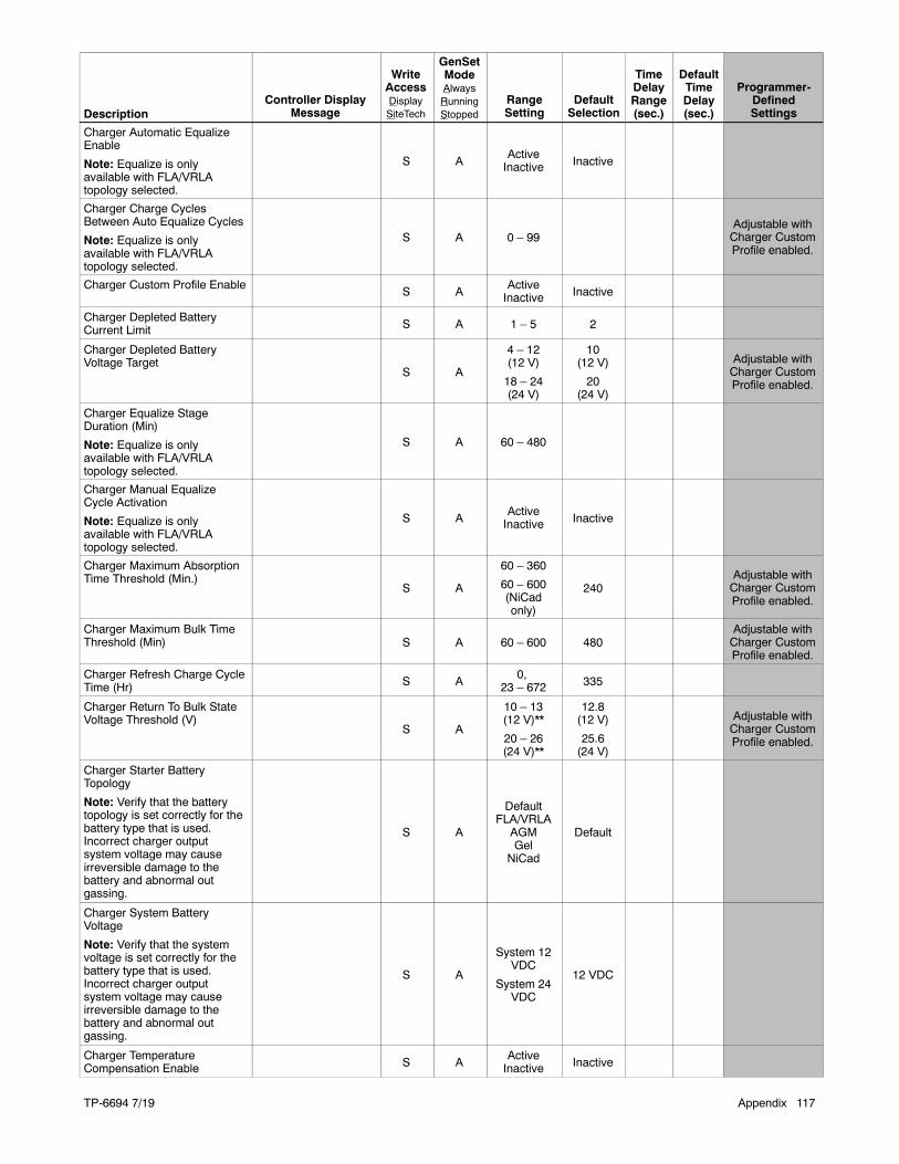
TP-6694 7/19 Appendix 117
Description
Programmer-DefinedSettings
DefaultTimeDelay(sec.)
TimeDelayRange(sec.)
DefaultSelection
RangeSetting
GenSetModeAlwaysRunningStopped
WriteAccessDisplaySiteTech
Controller DisplayMessage
Charger Automatic EqualizeEnable
Note: Equalize is onlyavailable with FLA/VRLAtopology selected.
S AActiveInactive Inactive
Charger Charge CyclesBetween Auto Equalize Cycles
Note: Equalize is onlyavailable with FLA/VRLAtopology selected.
S A 0 – 99Adjustable withCharger CustomProfile enabled.
Charger Custom Profile EnableS A
ActiveInactive Inactive
Charger Depleted BatteryCurrent Limit S A 1 – 5 2
Charger Depleted BatteryVoltage Target
S A
4 – 12(12 V)
18 – 24(24 V)
10(12 V)
20(24 V)
Adjustable withCharger CustomProfile enabled.
Charger Equalize StageDuration (Min)
Note: Equalize is onlyavailable with FLA/VRLAtopology selected.
S A 60 – 480
Charger Manual EqualizeCycle Activation
Note: Equalize is onlyavailable with FLA/VRLAtopology selected.
S AActiveInactive Inactive
Charger Maximum AbsorptionTime Threshold (Min.)
S A
60 – 360
60 – 600(NiCadonly)
240Adjustable withCharger CustomProfile enabled.
Charger Maximum Bulk TimeThreshold (Min) S A 60 – 600 480
Adjustable withCharger CustomProfile enabled.
Charger Refresh Charge CycleTime (Hr) S A
0,23 – 672 335
Charger Return To Bulk StateVoltage Threshold (V)
S A
10 – 13(12 V)**
20 – 26(24 V)**
12.8(12 V)
25.6(24 V)
Adjustable withCharger CustomProfile enabled.
Charger Starter BatteryTopology
Note: Verify that the batterytopology is set correctly for thebattery type that is used.Incorrect charger outputsystem voltage may causeirreversible damage to thebattery and abnormal outgassing.
S A
DefaultFLA/VRLA
AGMGel
NiCad
Default
Charger System BatteryVoltage
Note: Verify that the systemvoltage is set correctly for thebattery type that is used.Incorrect charger outputsystem voltage may causeirreversible damage to thebattery and abnormal outgassing.
S A
System 12VDC
System 24VDC
12 VDC
Charger TemperatureCompensation Enable S A
ActiveInactive Inactive
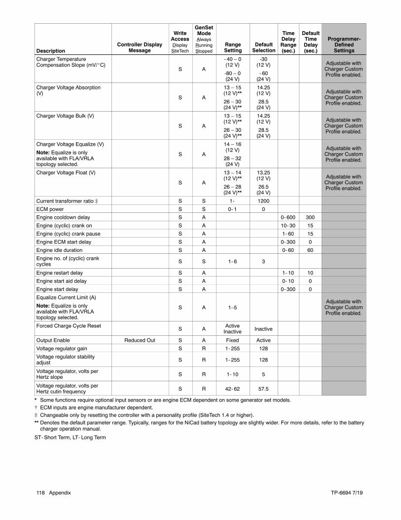
TP-6694 7/19118 Appendix
Description
Programmer-DefinedSettings
DefaultTimeDelay(sec.)
TimeDelayRange(sec.)
DefaultSelection
RangeSetting
GenSetModeAlwaysRunningStopped
WriteAccessDisplaySiteTech
Controller DisplayMessage
Charger TemperatureCompensation Slope (mV/_C)
S A
- 40 – 0(12 V)
-80 – 0(24 V)
-30(12 V)
- 60(24 V)
Adjustable withCharger CustomProfile enabled.
Charger Voltage Absorption(V)
S A
13 – 15(12 V)**
26 – 30(24 V)**
14.25(12 V)
28.5(24 V)
Adjustable withCharger CustomProfile enabled.
Charger Voltage Bulk (V)
S A
13 – 15(12 V)**
26 – 30(24 V)**
14.25(12 V)
28.5(24 V)
Adjustable withCharger CustomProfile enabled.
Charger Voltage Equalize (V)
Note: Equalize is onlyavailable with FLA/VRLAtopology selected.
S A
14 – 16(12 V)
28 – 32(24 V)
Adjustable withCharger CustomProfile enabled.
Charger Voltage Float (V)
S A
13 – 14(12 V)**
26 – 28(24 V)**
13.25(12 V)
26.5(24 V)
Adjustable withCharger CustomProfile enabled.
Current transformer ratio ] S S 1- 1200
ECM power S S 0- 1 0
Engine cooldown delay S A 0- 600 300
Engine (cyclic) crank on S A 10- 30 15
Engine (cyclic) crank pause S A 1- 60 15
Engine ECM start delay S A 0- 300 0
Engine idle duration S A 0- 60 60
Engine no. of (cyclic) crankcycles S S 1- 6 3
Engine restart delay S A 1- 10 10
Engine start aid delay S A 0- 10 0
Engine start delay S A 0- 300 0
Equalize Current Limit (A)
Note: Equalize is onlyavailable with FLA/VRLAtopology selected.
S A 1–5Adjustable withCharger CustomProfile enabled.
Forced Charge Cycle ResetS A
ActiveInactive Inactive
Output Enable Reduced Out S A Fixed Active
Voltage regulator gain S R 1- 255 128
Voltage regulator stabilityadjust S R 1- 255 128
Voltage regulator, volts perHertz slope S R 1- 10 5
Voltage regulator, volts perHertz cutin frequency S R 42- 62 57.5
* Some functions require optional input sensors or are engine ECM dependent on some generator set models.[ ECM inputs are engine manufacturer dependent.] Changeable only by resetting the controller with a personality profile (SiteTech 1.4 or higher).** Denotes the default parameter range. Typically, ranges for the NiCad battery topology are slightly wider. For more details, refer to the batterycharger operation manual.
ST- Short Term, LT- Long Term

TP-6694 7/19 Appendix 119
Notes
TP-6694 7/19120 Appendix
Appendix C Voltage Regulator Definitions and Adjustments
The following definitions and adjustment/settingspecifications are intended for users planning to adjustthe voltage regulator beyond the default settings inorder to customize the alternator for a specificapplication.
This information is not intended to be a comprehensiveexplanation of all the terms mentioned. There arenumerous documents available that define these termsmore completely than described herein. Any userplanning to change the generator set controlleradjustment settings or to apply the generator set tothese types of applications should understand theseterms.
This appendix contains references to other sections ofthis manual. Please refer to these sections for furtherinformation and explanation.
Paralleling generator sets can be a complicated anddangerous exercise. Application programming must beperformed by appropriately skilled and suitably-trainedpersonnel.
Definitions
Underfrequency Unloading
Underfrequency unloading is a function used in thealternator excitation control system to improve theoverall generator set system (engine and alternator)response. In particular, underfrequency unloadingrelates to large-block load applications. When appliedto engine-driven alternators, large-block loads cause asubsequent transient torque load on the engine. Thistorque load can reduce the engine’s speed below thenormal operating point. Typically, the engine speedcontroller or governor will compensate for this bycommanding an increase in fuel. If, however, the fuelsystem is inadequate to recover from a relatively largeload, the speed may never recover. In these instances,other measures must be taken. This is where theunderfrequency unloading occurs.
When the excitation control system detects a drop in thespeed or electrical frequency below somepredetermined point, the control system enters anunloading condition. This can be described as movingto a lower voltage regulation point. By reducing theoutput voltage of the alternator, the load on thegenerator set is reduced. This can be shown
mathematically byOhm’s law,which states that power isequal to the voltage squared divided by the impedance.As the voltage is reduced, the power delivered by thealternator decreases by a squared relationship. Since itis the power in the alternator that translates into enginetorque, the engine load is also reduced.
By changing various parameters of this compensationtechnique, the controlling system can be tailored tomatch the performance capabilities of most engine andalternator combinations. The point at which theunloading begins to act or how much unloading occurscan be adjusted to impact maximum voltage droop,maximum speed droop, or time to recover. Someapplications may not need unloading and, in thesecases, set the unloading parameter to disable thefunction. These parameters are further describedbelow. An example is provided to help clarify therelationship between these parameters.
Underfrequency Unload Slope
Underfrequency unload slope is the term used todescribe the amount that the voltage is reduced,per-cycle-per-second or per-hertz (Hz), when in anunderfrequency condition. The slope or schedule issometimes called the volts-per-hertz slope. When theelectrical frequency drops below the cut-in point (seebelow), the excitation control system temporarilyreduces the regulated voltage to reduce the subsequenttorque on the engine. The amount that the controlsystem reduces voltage is defined as the product ormultiplication of the slope and the amount of frequencyor speed below the cut-in point. For every Hz below thecut-in point, the control system reduces the line-to-linevoltage by an amount equal to the slope.
Because each engine responds differently to thevarious loads encountered, the slope may be adjustedto improve the system response. If, when large loadsare applied to the generator set, the engine speed dropsbelow the acceptable limit (as determined by theparticular loads applied), the slope may need to beincreased. Increasing the slopewill cause the voltage todroop more during load applications, consequentlyreducing the load torque on the engine and allowing thespeed to increase. If, however, the voltage drops belowan acceptable lower limit (as determined by theparticular loads connected to the generator set), a lowerslope may work better. The underfrequency unloadingfunction may be disabled by setting the slope to zero.
TP-6694 7/19 Appendix 121
Frequency Setpoint or Cut-In Point
Thepoint atwhich the underfrequency unloadingbeginsto take effect is adjustable, allowing the system to betailored for each application. Because thecharacteristics of the engine have the largest effect onthe system’s performance, the engine’s responseshould determine the unloading point. The unloadingsetpoint is the frequency below which the excitationcontrol will reduce the voltage so that the engine maybegin to recover.
The cut-in point, or frequency setpoint, should be set0.5- 3.0 Hz lower than the normal steady-state band ofoperation. If the engine normally operates within a verynarrow range of speeds close to the nominal, a setpointof 0.5 to 1.0 Hz below nominal should be suitable. If theengine normally operates over a wide range of speeds,the setpoint may need to be 2.0- 3.0 Hz from thenominal. The underfrequency unloading function canbe eliminated by setting the cut-in point below theminimum expected operating frequency.
Example
A90 kW load is applied to a 100 kW, 60Hz generator setdriven by a turbocharged diesel engine with anelectronic controlmodule (ECM). The speed drops 10%and takes 20 seconds to recover to at least 59.5Hz. Thevoltage,meanwhile, drops from480 to 460and recoversto 480 within 15 seconds. Therefore, someunderfrequency unloading should be provided. A goodstarting point would be a frequency setpoint or cut-in of59 Hz. A slope of 15 volts per-cycle-per-second isappropriate as well. If after these adjustments thespeed recovers very quickly, in about 5 seconds, but thevoltage drops below 440 volts, the slope should bereduced to 12 volts per cycle. More adjusting may berequired to get themost desirable compromise betweenspeed and voltage.
Three-Phase Sensing
Three-phase sensing describes how the excitationcontrol or voltage regulator determines the condition ofthe alternator output voltage. Early types of regulatorssensed the voltage on just one phase of the alternator.Single-phase sensing is not uncommon today as mostalternators are designed to produce balanced, equalvoltage on all three phases. If the loads applied to thegenerator set including no load are equal and balanced,the output voltage on each phase will be nearly equal.
However, in some applications, individual phases mayhave unequal or unbalanced loads. In these cases, theoutput voltages will not be equal on each phase. In
general, the phase with the greatest load will have thelowest voltage while the phase with the least load willhave the highest voltage. This is true regardless of thetype of sensing used in the regulator system. Asingle-phase sensing excitation controller will keep thevoltage of the sensed phase at the voltage adjustmentvalue. A three-phase sensing system will average thethree phases and hold the average to the adjustmentsetting. The average is the sum of the voltages of threephases divided by 3.
As stated above, three-phase sensing does noteliminate the unequal voltage phenomenon.Three-phase sensing balances the inequality of voltagebetween the phases to the desired value. In otherwords, if a system with unbalanced loads uses asingle-phase control feedback, the voltage on thesensed phase would be at the setpoint while the othertwo phases would vary by their proportional loads. Forexample, if the sensed phase had rated load while thetwo other phases were only loaded at half the ratedvalue, those two phases would have higher-than-ratedvoltage which may be undesirable. If a three-phasesensing feedback were utilized, the phase with ratedload would be regulated to a voltage slightly below therated voltage while the other two phases would beslightly above the rated voltage (but lower than in theprevious case). The sum of the three, divided by 3,would be equal to the regulation setpoint.
In a single-phase system, line-to-line voltage is heldequal to the line-to-line voltage adjust setting. In athree-phase system, theaverageof the three line-to-linevoltage is regulated to the voltage adjust setting. Insome cases, it may be desirable to keep one phase at aparticular value. Modify the voltageadjust setting higheror lower accordingly for any unique requirements for theparticular application.
Adjustment and SettingSpecifications
Voltage Adjust
The voltage adjust is entered as the rated or otherwisedesired line-to-line voltage. The average of theline-to-line voltages is then regulated to thecorresponding value as previously described. Thesetting may be as fine as tenths of volts. The voltageadjust defaults to the rated system voltage wheneverthe system voltage is changed. The voltage adjust maybe set to any value within 10% of the system voltage.The upper limit is 10% above the system voltage andthe lower limit is 10% below the system voltage.
TP-6694 7/19122 Appendix
As a reference, the present voltage adjust setting isdisplayed as well as the average value of the line-to-linevoltages. The individual line-to-line voltages are alsodisplayed on the subsequent menu screens. Thisallows the user to monitor any individual phase, ifdesired.
The voltage adjust setting may be changed by meansother than the menu including user-defined digital inputor remote communications. If voltage adjustmentoccurs, the new value will be displayed accordingly inthe voltage adjust menu.
Underfrequency Unload Enable
The underfrequency unload enablemenu is used to turnthe underfrequency unload on or off. A YES entry willturn the feature on and the display will show ENABLEDYES. A NO entry will turn the feature off and the displaywill show ENABLED NO. The underfrequency unloaddefaults to an enabled (ON) condition.
Frequency Setpoint
The frequency setpoint is the cut-in point forunderfrequency unloading. At any operating frequencybelow the frequency setpoint, the output voltage will bereduced. The frequencymay be entered with resolutionto tenths of a Hz. The range of acceptable entries is 30to 70 Hz. The default value is one cycle-per-second (ortwo for non-ECM engines) below the normal systemfrequency. The frequency setpoint changes to thedefault value if the system frequency changes. A settingof 30Hz essentially disables the underfrequency unloadfeature because most engines do not normally drop tospeeds this low, even during load applications.
Underfrequency Unload Slope
The slope determines how much voltage is reducedduring an unloading condition. The line-to-line voltageis regulated to a value less than the voltage adjustsetting by this amount for every cycle below thefrequency setpoint. The voltage may be entered withresolution as fine as one-tenth of one volt. The defaultvalue is 2.0 volts per-cycle-per-second. A zero entry forthe slope in effect turns the underfrequency unloadfeature off.

TP-6694 7/19 Appendix 123
Notes
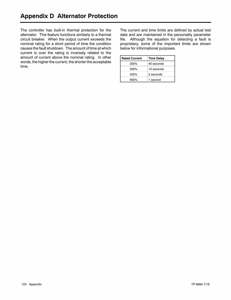
TP-6694 7/19124 Appendix
Appendix D Alternator Protection
The controller has built-in thermal protection for thealternator. This feature functions similarly to a thermalcircuit breaker. When the output current exceeds thenominal rating for a short period of time the conditioncauses the fault shutdown. The amount of time at whichcurrent is over the rating is inversely related to theamount of current above the nominal rating. In otherwords, the higher the current, the shorter the acceptabletime.
The current and time limits are defined by actual testdata and are maintained in the personality parameterfile. Although the equation for detecting a fault isproprietary, some of the important limits are shownbelow for informational purposes.
Rated Current Time Delay
200% 40 seconds
300% 10 seconds
425% 5 seconds
950% 1 second

TP-6694 7/19 Appendix 125
Notes

TP-6694 7/19126 Appendix
Appendix E Controller Displays from the Engine ECM
The controller display showing engine information isdependent upon the engine manufacturer and thecorresponding Engine Control Module (ECM). Thefollowing list indicates which engine displays areavailable by the engine manufacturer. This informationis subject to change by the engine manufacturer.
Note: See the generator set specification sheet forengine model identification.
Some engines do not have an ECM and in some casesthe ECM information is not available as a controllerdisplay. In these situations, critical information like oilpressure and coolant temperature are displayed by thecontroller using independent engine sensors not usedby the ECM.
Controller Displaysas Provided by the
Engine ECM
Engine Manufacturer (and model)
KohlerDiesel
(KDI M, TM*)
KohlerDiesel
(KDI TCR)
Kohler Gas(KG2204,KG2204T)
GM/PSI andKohler Gas(KG6208,KG6208T) DD/MTU Doosan
JohnDeere Volvo
Intake air pressure S/D DIntake air Temperature D D S/D D D DCoolant level D D D D D DCoolant temperature D C/S/D C/S/D C/S/D C/S/D C/S/D C/S/DCrankcase pressure DECM battery voltage S S/D S S SEngine model number S S S S S S SEngine serial number S S S S S S SEngine speed C/S/D C/S/D C/S/D C/S/D C/S/D C/S/D C/S/D C/S/DFuel pressure D C/S/D C/S C/S/D C/S[ C/S/DFuel rate S S S S SFuel temperature D S S/D SOil level S[ S/D[ S[ S[ S[Oil pressure C/S/D D C/S/D C/S/D C/S/D C/S/D C/S/DOil temperature S D SDC = Value displayed on controller, S = Value displayed in Site Tech, D = ECU diagnostic is supported
* Electronic governor and ECM are optional on KDI M and TM engines.
[ Controller uses local analog input to obtain this information
NOTE: REOZMD/ROZMC (Mitsubishi engines) have an ECM but do not send signals to the generator set controller.

TP-6694 7/19 Appendix 127
Notes

Original Instructions (English)
E 2010, 2011, 2014, 2015, 2017, 2018, 2019 by Kohler Co. All rights reserved.
TP-6694 7/19lKOHLER CO., Kohler, Wisconsin 53044Phone 920-457-4441, Fax 920-459-1646For the nearest sales/service outlet in theUS and Canada, phone 1-800-544-2444KOHLERPower.com