Embed Size (px)
Citation preview
Industrial Generator Sets
Models:
20--2000 kW
Controllers:Decision-Maker 3+, 16-LightSoftware (Code) Version 1.10 or higher
Decision-Maker 1
TP-6161 6/05b
Operation
TP-6161 6/052
Engine exhaust from this product contains chemicals
known to the State of California to cause cancer, birth
defects, or other reproductive harm.
WARNING
California Proposition 65
Product Identification Information
Product identification numbers determine service parts.
Record the product identification numbers in the spaces
below immediately after unpacking the products so that
the numbers are readily available for future reference.
Record field-installed kit numbers after installing the
kits.
Generator Set Identification Numbers
Record the product identification numbers from the
generator set nameplate(s).
Model Designation
Specification Number
Serial Number
Accessory Number Accessory Description
Controller Identification
Record the controller description from the generator set
operation manual, spec sheet, or sales invoice.
Controller Description
Engine Identification
Record the product identification information from the
engine nameplate.
Manufacturer
Model Designation
Serial Number
Table of Contents
TP-6161 6/05 Table of Contents 3
Product Identification Information 2. . . . . . . . . . . . . . . . . . . . . . . . . . . . . . . . . . . . . . . . . . . . . . . . . . . . . . . . . . . .
Safety Precautions and Instructions 5. . . . . . . . . . . . . . . . . . . . . . . . . . . . . . . . . . . . . . . . . . . . . . . . . . . . . . . .
Introduction 11. . . . . . . . . . . . . . . . . . . . . . . . . . . . . . . . . . . . . . . . . . . . . . . . . . . . . . . . . . . . . . . . . . . . . . . . . . . . . . .
Abbreviations 11. . . . . . . . . . . . . . . . . . . . . . . . . . . . . . . . . . . . . . . . . . . . . . . . . . . . . . . . . . . . . .
List of Related Materials 11. . . . . . . . . . . . . . . . . . . . . . . . . . . . . . . . . . . . . . . . . . . . . . . . . . . . .
Service Assistance 12. . . . . . . . . . . . . . . . . . . . . . . . . . . . . . . . . . . . . . . . . . . . . . . . . . . . . . . . . . . . . . . . . . . . . . . .
Section 1 Specifications and Features 13. . . . . . . . . . . . . . . . . . . . . . . . . . . . . . . . . . . . . . . . . . . . . . . . . . . . . .
1.1 Introduction 13. . . . . . . . . . . . . . . . . . . . . . . . . . . . . . . . . . . . . . . . . . . . . . . . . . . . . . . . . .
1.2 16-Light Controller Features 13. . . . . . . . . . . . . . . . . . . . . . . . . . . . . . . . . . . . . . . . . . . .
1.2.1 Annunciator Panel Lamps 14. . . . . . . . . . . . . . . . . . . . . . . . . . . . . . . . . . . . . .
1.2.2 Auxiliary Fault Lamp 15. . . . . . . . . . . . . . . . . . . . . . . . . . . . . . . . . . . . . . . . . . .
1.2.3 Fuses 15. . . . . . . . . . . . . . . . . . . . . . . . . . . . . . . . . . . . . . . . . . . . . . . . . . . . . . .
1.2.4 Analog Meters and Gauges 15. . . . . . . . . . . . . . . . . . . . . . . . . . . . . . . . . . . . .
1.2.5 Switches and Controls 16. . . . . . . . . . . . . . . . . . . . . . . . . . . . . . . . . . . . . . . . .
1.2.6 Terminal Strips 16. . . . . . . . . . . . . . . . . . . . . . . . . . . . . . . . . . . . . . . . . . . . . . . .
1.2.7 DIP Switches 17. . . . . . . . . . . . . . . . . . . . . . . . . . . . . . . . . . . . . . . . . . . . . . . . .
1.3 Expanded Decision-Maker 1 Controller 18. . . . . . . . . . . . . . . . . . . . . . . . . . . . . . . . . . .
Section 2 Operation 19. . . . . . . . . . . . . . . . . . . . . . . . . . . . . . . . . . . . . . . . . . . . . . . . . . . . . . . . . . . . . . . . . . . . . . .
2.1 Prestart Checklist 19. . . . . . . . . . . . . . . . . . . . . . . . . . . . . . . . . . . . . . . . . . . . . . . . . . . . .
2.2 Generator Set Exercising 19. . . . . . . . . . . . . . . . . . . . . . . . . . . . . . . . . . . . . . . . . . . . . . .
2.3 16-Light Controller Features 19. . . . . . . . . . . . . . . . . . . . . . . . . . . . . . . . . . . . . . . . . . . .
2.3.1 Normal Operation 19. . . . . . . . . . . . . . . . . . . . . . . . . . . . . . . . . . . . . . . . . . . . .
2.3.2 Prime Power Mode Operation 20. . . . . . . . . . . . . . . . . . . . . . . . . . . . . . . . . .
2.3.3 Emergency Stopping 20. . . . . . . . . . . . . . . . . . . . . . . . . . . . . . . . . . . . . . . . . .
2.3.4 Fault Shutdowns 21. . . . . . . . . . . . . . . . . . . . . . . . . . . . . . . . . . . . . . . . . . . . . .
2.3.5 Controller Resetting After a Fault Shutdown 21. . . . . . . . . . . . . . . . . . . . . . .
2.4 Expanded Decision-Maker 1 Controller 22. . . . . . . . . . . . . . . . . . . . . . . . . . . . . . . . . . .
2.4.1 Generator Set Starting 22. . . . . . . . . . . . . . . . . . . . . . . . . . . . . . . . . . . . . . . . .
2.4.2 Generator Set Stopping 22. . . . . . . . . . . . . . . . . . . . . . . . . . . . . . . . . . . . . . . .
2.4.3 Fault Shutdowns 22. . . . . . . . . . . . . . . . . . . . . . . . . . . . . . . . . . . . . . . . . . . . . .
2.4.4 Controller Resetting After a Fault Shutdown 22. . . . . . . . . . . . . . . . . . . . . . .
Section 3 Scheduled Maintenance 23. . . . . . . . . . . . . . . . . . . . . . . . . . . . . . . . . . . . . . . . . . . . . . . . . . . . . . . . . .
3.1 Alternator Service 23. . . . . . . . . . . . . . . . . . . . . . . . . . . . . . . . . . . . . . . . . . . . . . . . . . . . .
3.2 Engine Service 23. . . . . . . . . . . . . . . . . . . . . . . . . . . . . . . . . . . . . . . . . . . . . . . . . . . . . . .
3.3 Service Schedule 24. . . . . . . . . . . . . . . . . . . . . . . . . . . . . . . . . . . . . . . . . . . . . . . . . . . . .
3.4 Alternator Bearing Service 26. . . . . . . . . . . . . . . . . . . . . . . . . . . . . . . . . . . . . . . . . . . . . .
3.4.1 20--300 kW Models 26. . . . . . . . . . . . . . . . . . . . . . . . . . . . . . . . . . . . . . . . . . . .
3.4.2 350--2000 kW Models with Single- Bearing Alternator 26. . . . . . . . . . . . . .
3.4.3 1250--2000 kW Model with Two- Bearing Alternator 26. . . . . . . . . . . . . . . .
3.5 Diesel Fuel Systems 26. . . . . . . . . . . . . . . . . . . . . . . . . . . . . . . . . . . . . . . . . . . . . . . . . . .
3.5.1 Bleeding Air from the Fuel System 26. . . . . . . . . . . . . . . . . . . . . . . . . . . . . . .
3.5.2 Subbase Inner Fuel Tank Alarm 27. . . . . . . . . . . . . . . . . . . . . . . . . . . . . . . . .
3.6 Gas/Gasoline Fuel Systems 28. . . . . . . . . . . . . . . . . . . . . . . . . . . . . . . . . . . . . . . . . . . .
3.6.1 Gaseous Fuel System Concept 28. . . . . . . . . . . . . . . . . . . . . . . . . . . . . . . . .
3.6.2 LP Liquid Withdrawal Fuel System Concept 28. . . . . . . . . . . . . . . . . . . . . . .
3.6.3 LP Gas/Natural Gas Conversion for Straight Gas Fuel System 28. . . . . . .
3.6.4 Fuel System Changeover Kits 29. . . . . . . . . . . . . . . . . . . . . . . . . . . . . . . . . . .
3.6.5 Carburetor Adjustment 29. . . . . . . . . . . . . . . . . . . . . . . . . . . . . . . . . . . . . . . . .
3.6.6 Fuel System Maintenance 30. . . . . . . . . . . . . . . . . . . . . . . . . . . . . . . . . . . . . .
Table of Contents, continued
TP-6161 6/05Table of Contents4
3.7 Cooling System 30. . . . . . . . . . . . . . . . . . . . . . . . . . . . . . . . . . . . . . . . . . . . . . . . . . . . . . .
3.7.1 Coolant Level Check 30. . . . . . . . . . . . . . . . . . . . . . . . . . . . . . . . . . . . . . . . . . .
3.7.2 Cooling System Component Inspection 31. . . . . . . . . . . . . . . . . . . . . . . . . . .
3.7.3 Cooling System Drainage Procedure 31. . . . . . . . . . . . . . . . . . . . . . . . . . . . .
3.7.4 Cooling System Flush and Clean Procedure 31. . . . . . . . . . . . . . . . . . . . . .
3.7.5 Cooling System Refilling Procedure 31. . . . . . . . . . . . . . . . . . . . . . . . . . . . . .
3.8 Fan Bearing Lubrication 32. . . . . . . . . . . . . . . . . . . . . . . . . . . . . . . . . . . . . . . . . . . . . . . .
3.9 Battery 33. . . . . . . . . . . . . . . . . . . . . . . . . . . . . . . . . . . . . . . . . . . . . . . . . . . . . . . . . . . . . . .
3.9.1 Cleaning 35. . . . . . . . . . . . . . . . . . . . . . . . . . . . . . . . . . . . . . . . . . . . . . . . . . . . .
3.9.2 Electrolyte Level Inspection 35. . . . . . . . . . . . . . . . . . . . . . . . . . . . . . . . . . . . .
3.9.3 Specific Gravity Check 35. . . . . . . . . . . . . . . . . . . . . . . . . . . . . . . . . . . . . . . . .
3.9.4 Charging 36. . . . . . . . . . . . . . . . . . . . . . . . . . . . . . . . . . . . . . . . . . . . . . . . . . . . .
3.10 Detroit Diesel Engine Control Systems 36. . . . . . . . . . . . . . . . . . . . . . . . . . . . . . . . . . .
3.10.1 Features 36. . . . . . . . . . . . . . . . . . . . . . . . . . . . . . . . . . . . . . . . . . . . . . . . . . . . .
3.10.2 DDEC Engine Diagnostics 36. . . . . . . . . . . . . . . . . . . . . . . . . . . . . . . . . . . . . .
3.11 Engine Control Systems 37. . . . . . . . . . . . . . . . . . . . . . . . . . . . . . . . . . . . . . . . . . . . . . . .
3.12 Storage Procedure 37. . . . . . . . . . . . . . . . . . . . . . . . . . . . . . . . . . . . . . . . . . . . . . . . . . . .
3.12.1 Lubricating System 37. . . . . . . . . . . . . . . . . . . . . . . . . . . . . . . . . . . . . . . . . . . .
3.12.2 Cooling System 38. . . . . . . . . . . . . . . . . . . . . . . . . . . . . . . . . . . . . . . . . . . . . . .
3.12.3 Fuel System 38. . . . . . . . . . . . . . . . . . . . . . . . . . . . . . . . . . . . . . . . . . . . . . . . . .
3.12.4 Internal Engine Components (Gas/Gasoline-Fueled Engines) 38. . . . . . .
3.12.5 Exterior 38. . . . . . . . . . . . . . . . . . . . . . . . . . . . . . . . . . . . . . . . . . . . . . . . . . . . . .
3.12.6 Battery 39. . . . . . . . . . . . . . . . . . . . . . . . . . . . . . . . . . . . . . . . . . . . . . . . . . . . . . .
Section 4 Troubleshooting 41. . . . . . . . . . . . . . . . . . . . . . . . . . . . . . . . . . . . . . . . . . . . . . . . . . . . . . . . . . . . . . . . .
Section 5 Generator Set Reconnection 45. . . . . . . . . . . . . . . . . . . . . . . . . . . . . . . . . . . . . . . . . . . . . . . . . . . . .
5.1 Voltage Reconnection 45. . . . . . . . . . . . . . . . . . . . . . . . . . . . . . . . . . . . . . . . . . . . . . . . .
5.2 Overvoltage Shutdown Adjustment (16-Light Controller only) 50. . . . . . . . . . . . . . . .
Section 6 Accessories 53. . . . . . . . . . . . . . . . . . . . . . . . . . . . . . . . . . . . . . . . . . . . . . . . . . . . . . . . . . . . . . . . . . . . .
6.1 Accessories and Connections 53. . . . . . . . . . . . . . . . . . . . . . . . . . . . . . . . . . . . . . . . . . .
6.1.1 Audiovisual Alarm (M) 53. . . . . . . . . . . . . . . . . . . . . . . . . . . . . . . . . . . . . . . . . .
6.1.2 Common Failure Relay Kit (M) 53. . . . . . . . . . . . . . . . . . . . . . . . . . . . . . . . . .
6.1.3 Controller Connection Kit (M) 53. . . . . . . . . . . . . . . . . . . . . . . . . . . . . . . . . . .
6.1.4 Dry Contact Kit (Single Relay) (M) 54. . . . . . . . . . . . . . . . . . . . . . . . . . . . . . .
6.1.5 Dry Contact Kits (10, 14, and 20 Relay) (M) 54. . . . . . . . . . . . . . . . . . . . . . .
6.1.6 Engine Prealarm Senders (M) 55. . . . . . . . . . . . . . . . . . . . . . . . . . . . . . . . . . .
6.1.7 FASTCHECK Diagnostic Tester (M) 55. . . . . . . . . . . . . . . . . . . . . . . . . . . . . .
6.1.8 Float/Equalize Battery Charger Kit with Alarm Option (M) 55. . . . . . . . . . .
6.1.9 Line Circuit Breaker 55. . . . . . . . . . . . . . . . . . . . . . . . . . . . . . . . . . . . . . . . . . .
6.1.10 Low Fuel Switch (M) 56. . . . . . . . . . . . . . . . . . . . . . . . . . . . . . . . . . . . . . . . . . .
6.1.11 Remote Annunciator Kit (M) 56. . . . . . . . . . . . . . . . . . . . . . . . . . . . . . . . . . . .
6.1.12 Remote Emergency Stop Kit (M) 56. . . . . . . . . . . . . . . . . . . . . . . . . . . . . . . .
6.1.13 Remote Serial Annunciator (M) 57. . . . . . . . . . . . . . . . . . . . . . . . . . . . . . . . . .
6.1.14 Run Relay Kit 57. . . . . . . . . . . . . . . . . . . . . . . . . . . . . . . . . . . . . . . . . . . . . . . . .
6.1.15 Safeguard Breaker 57. . . . . . . . . . . . . . . . . . . . . . . . . . . . . . . . . . . . . . . . . . . .
6.1.16 Accessory and Prime Power Terminal Strip Connections (M) 58. . . . . . . .
Appendix A Abbreviations 61. . . . . . . . . . . . . . . . . . . . . . . . . . . . . . . . . . . . . . . . . . . . . . . . . . . . . . . . . . . . . . . .
TP-6161 6/05 5Safety Precautions and Instructions
Safety Precautions and Instructions
IMPORTANT SAFETY INSTRUCTIONS.
Electromechanical equipment,including generator sets, transferswitches,switchgear, andaccessories,
can cause bodily harm and poselife-threatening danger whenimproperly installed, operated, ormaintained. To prevent accidents beaware of potential dangers and actsafely. Read and follow all safety
precautions and instructions. SAVETHESE INSTRUCTIONS.
Thismanual hasseveral typesofsafetyprecautions and instructions: Danger,Warning, Caution, and Notice.
DANGER
Danger indicates the presence of ahazard that will cause severe
personal injury,death, orsubstantialproperty damage.
WARNING
Warning indicates the presence of ahazard that can cause severe
personal injury,death,orsubstantialproperty damage.
CAUTION
Caution indicates the presence of ahazard that will or can cause minor
personal injury or property damage.
NOTICE
Notice communicates installation,operation, or maintenance informationthat is safety related but not hazardrelated.
Safety decals affixed to the equipment
in prominent places alert the operatoror service technician to potentialhazards and explain how to act safely.The decals are shown throughout thispublication to improve operatorrecognition. Replace missing or
damaged decals.
Accidental Starting
Accidental starting.Can cause severe injury or death.
Disconnect the battery cables beforeworking on the generator set.
Remove the negative (--) lead firstwhen disconnecting the battery.Reconnect the negative (--) lead lastwhen reconnecting the battery.
WARNING
Disabling the generator set.Accidental starting can causesevere injury or death. Beforeworking on the generator set orconnected equipment, disable the
generator set as follows: (1) Move thegenerator set master switch to theOFFposition. (2) Disconnect the power tothe battery charger. (3) Remove thebattery cables, negative (--) lead first.Reconnect the negative (--) lead last
when reconnecting the battery. Followthese precautions to prevent starting ofthe generator set by an automatictransfer switch, remote start/stopswitch, or engine start command fromaremote computer.
Battery
Sulfuric acid in batteries.Can cause severe injury or death.
Wear protective goggles andclothing. Battery acid may cause
blindness and burn skin.
WARNING
Explosion.Can cause severe injury or death.Relays in the battery chargercause arcs or sparks.
Locate the battery in awell-ventilatedarea. Isolate thebattery charger fromexplosive fumes.
WARNING
Battery electrolyte is a dilutedsulfuric acid. Batteryacidcancausesevere injury or death. Battery acid
can cause blindness and burn skin.Always wear splashproof safetygoggles, rubber gloves, and bootswhen servicing the battery. Do notopen a sealed battery or mutilate thebattery case. If battery acid splashes in
the eyes or on the skin, immediatelyflush the affected area for 15 minuteswith large quantities of clean water.Seek immediatemedical aid in thecaseof eye contact. Never add acid to a
battery after placing the battery inservice, as thismay result inhazardousspattering of battery acid.
Battery acid cleanup. Battery acidcan cause severe injury or death.Battery acid is electrically conductive
and corrosive. Add 500 g (1 lb.) ofbicarbonate of soda (baking soda) to acontainer with 4 L (1 gal.) of water andmix the neutralizing solution. Pour theneutralizing solution on the spilledbattery acid and continue to add the
neutralizing solution to the spilledbattery acid until all evidence of achemical reaction (foaming) hasceased. Flush the resulting liquid withwater and dry the area.
Battery gases. Explosion can cause
severe injury or death. Battery gasescan cause an explosion. Do not smokeorpermit flamesor sparks to occurneara battery at any time, particularly whenit is charging. Do not dispose of abattery in a fire. To prevent burns and
sparks that could cause an explosion,avoid touching the battery terminalswith tools or other metal objects.Removeall jewelrybefore servicing theequipment. Discharge static electricityfrom your body before touching
batteries by first touching a grounded
TP-6161 6/056 Safety Precautions and Instructions
metal surfaceaway from thebattery. Toavoid sparks, do not disturb the batterycharger connections while the batteryis charging. Always turn the battery
charger off before disconnecting thebattery connections. Ventilate thecompartments containing batteries toprevent accumulation of explosivegases.
Battery short circuits. Explosion
can cause severe injury or death.Short circuits can cause bodily injuryand/or equipment damage.Disconnect the battery beforegenerator set installation ormaintenance. Remove all jewelry
before servicing the equipment. Usetools with insulated handles. Removethe negative (--) lead first whendisconnecting the battery. Reconnectthe negative (--) lead last whenreconnecting the battery. Never
connect the negative (--) battery cableto the positive (+) connection terminalof the starter solenoid. Do not test thebattery condition by shorting theterminals together.
Engine Backfire/FlashFire
Fire.Can cause severe injury or death.
Do not smoke or permit flames orsparks near fuels or the fuel system.
WARNING
Servicing the fuel system. A flashfirecancausesevere injuryordeath.Do not smoke or permit flames orsparks near the carburetor, fuel line,fuel filter, fuel pump, or other potential
sources of spilled fuels or fuel vapors.Catch fuels in an approved containerwhen removing the fuel line orcarburetor.
Servicing the air cleaner. A suddenbackfire can cause severe injury or
death. Do not operate the generatorset with the air cleaner removed.
Combustible materials. A fire cancause severe injury or death.Generator set engine fuels and fuel
vapors are flammable and explosive.Handle these materials carefully tominimize the risk of fire or explosion.
Equip the compartment or nearby areawith a fully charged fire extinguisher.Select a fire extinguisher rated ABC orBC for electrical fires or as
recommended by the local fire code oran authorized agency. Train allpersonnel on fire extinguisheroperation and fire preventionprocedures.
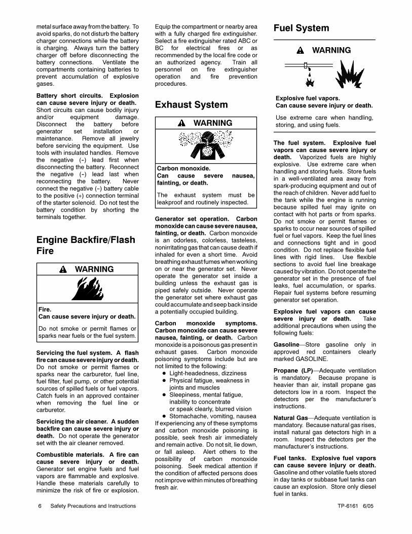
Exhaust System
Carbon monoxide.
Can cause severe nausea,
fainting, or death.
The exhaust system must be
leakproof and routinely inspected.
WARNING
Generator set operation. Carbonmonoxidecancauseseverenausea,fainting, or death. Carbon monoxideis an odorless, colorless, tasteless,
nonirritating gas that can cause death ifinhaled for even a short time. Avoidbreathingexhaust fumeswhenworkingon or near the generator set. Neveroperate the generator set inside abuilding unless the exhaust gas is
piped safely outside. Never operatethe generator set where exhaust gascouldaccumulateandseepback insidea potentially occupied building.
Carbon monoxide symptoms.Carbonmonoxide can cause severe
nausea, fainting, or death. Carbonmonoxide isapoisonousgaspresent inexhaust gases. Carbon monoxidepoisoning symptoms include but arenot limited to the following:
Light-headedness, dizziness
Physical fatigue, weakness injoints and muscles
Sleepiness, mental fatigue,inability to concentrateor speak clearly, blurred vision
Stomachache, vomiting, nauseaIf experiencing any of these symptomsand carbon monoxide poisoning ispossible, seek fresh air immediatelyand remain active. Do not sit, lie down,or fall asleep. Alert others to the
possibility of carbon monoxidepoisoning. Seek medical attention ifthe condition of affected persons doesnot improvewithinminutes of breathingfresh air.
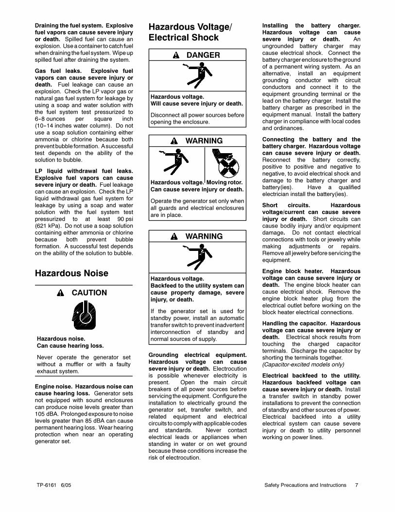
Fuel System
Explosive fuel vapors.
Can cause severe injury or death.
Use extreme care when handling,
storing, and using fuels.
WARNING
The fuel system. Explosive fuelvapors can cause severe injury ordeath. Vaporized fuels are highlyexplosive. Use extreme care whenhandling and storing fuels. Store fuels
in a well-ventilated area away fromspark-producing equipment and out ofthe reach of children. Never add fuel tothe tank while the engine is runningbecause spilled fuel may ignite oncontact with hot parts or from sparks.
Do not smoke or permit flames orsparks to occur near sources of spilledfuel or fuel vapors. Keep the fuel linesand connections tight and in goodcondition. Do not replace flexible fuellines with rigid lines. Use flexible
sections to avoid fuel line breakagecausedbyvibration. Donotoperate thegenerator set in the presence of fuelleaks, fuel accumulation, or sparks.Repair fuel systems before resuming
generator set operation.
Explosive fuel vapors can causesevere injury or death. Takeadditional precautions when using thefollowing fuels:
Gasoline—Store gasoline only in
approved red containers clearlymarked GASOLINE.
Propane (LP)—Adequate ventilationis mandatory. Because propane isheavier than air, install propane gasdetectors low in a room. Inspect the
detectors per the manufacturer’sinstructions.
Natural Gas—Adequate ventilation ismandatory. Because natural gas rises,install natural gas detectors high in a
room. Inspect the detectors per themanufacturer’s instructions.
Fuel tanks. Explosive fuel vaporscan cause severe injury or death.Gasoline and other volatile fuels storedin day tanks or subbase fuel tanks can
cause an explosion. Store only dieselfuel in tanks.
TP-6161 6/05 7Safety Precautions and Instructions
Draining the fuel system. Explosivefuel vapors can cause severe injuryor death. Spilled fuel can cause anexplosion. Useacontainer to catch fuel
whendraining the fuel system. Wipeupspilled fuel after draining the system.
Gas fuel leaks. Explosive fuelvapors can cause severe injury ordeath. Fuel leakage can cause anexplosion. Check the LP vapor gas or
natural gas fuel system for leakage byusing a soap and water solution withthe fuel system test pressurized to6--8 ounces per square inch(10--14 inches water column). Do not
use a soap solution containing eitherammonia or chlorine because bothpreventbubble formation. Asuccessfultest depends on the ability of thesolution to bubble.
LP liquid withdrawal fuel leaks.
Explosive fuel vapors can causesevere injury or death. Fuel leakagecan cause an explosion. Check the LPliquid withdrawal gas fuel system forleakage by using a soap and watersolution with the fuel system test
pressurized to at least 90 psi(621 kPa). Do not use a soap solutioncontaining either ammonia or chlorinebecause both prevent bubbleformation. A successful test dependson the ability of the solution to bubble.
Hazardous Noise
Hazardous noise.
Can cause hearing loss.
Never operate the generator set
without a muffler or with a faulty
exhaust system.
CAUTION
Engine noise. Hazardous noise cancause hearing loss. Generator setsnot equipped with sound enclosures
can produce noise levels greater than105 dBA. Prolongedexposure tonoiselevels greater than 85 dBA can causepermanent hearing loss. Wear hearingprotection when near an operatinggenerator set.
Hazardous Voltage/Electrical Shock
Hazardous voltage.Will cause severe injury or death.
Disconnect all power sources beforeopening the enclosure.
DANGER
Hazardous voltage.
Can cause severe injury or death.
Operate the generator set only when
all guards and electrical enclosures
are in place.
Moving rotor.
WARNING
Hazardous voltage.
Backfeed to the utility system can
cause property damage, severe
injury, or death.
If the generator set is used for
standby power, install an automatic
transfer switch to prevent inadvertent
interconnection of standby and
normal sources of supply.
WARNING
Grounding electrical equipment.
Hazardous voltage can causesevere injury or death. Electrocutionis possible whenever electricity ispresent. Open the main circuitbreakers of all power sources beforeservicing theequipment. Configure the
installation to electrically ground thegenerator set, transfer switch, andrelated equipment and electricalcircuits to complywithapplicablecodesand standards. Never contactelectrical leads or appliances when
standing in water or on wet groundbecause these conditions increase therisk of electrocution.
Installing the battery charger.Hazardous voltage can causesevere injury or death. Anungrounded battery charger may
cause electrical shock. Connect thebatterychargerenclosure to thegroundof a permanent wiring system. As analternative, install an equipmentgrounding conductor with circuitconductors and connect it to the
equipment grounding terminal or thelead on the battery charger. Install thebattery charger as prescribed in theequipment manual. Install the batterycharger in compliance with local codesand ordinances.
Connecting the battery and thebattery charger. Hazardous voltagecan cause severe injury or death.Reconnect the battery correctly,positive to positive and negative to
negative, to avoid electrical shock anddamage to the battery charger andbattery(ies). Have a qualifiedelectrician install the battery(ies).
Short circuits. Hazardousvoltage/current can cause severe
injury or death. Short circuits cancause bodily injury and/or equipmentdamage. Do not contact electricalconnections with tools or jewelry whilemaking adjustments or repairs.Removeall jewelrybefore servicing the
equipment.
Engine block heater. Hazardousvoltage can cause severe injury ordeath. The engine block heater cancause electrical shock. Remove theengine block heater plug from the
electrical outlet before working on theblock heater electrical connections.
Handling the capacitor. Hazardousvoltage can cause severe injury ordeath. Electrical shock results from
touching the charged capacitorterminals. Discharge the capacitor byshorting the terminals together.(Capacitor-excited models only)
Electrical backfeed to the utility.Hazardous backfeed voltage can
cause severe injury or death. Installa transfer switch in standby powerinstallations to prevent the connectionof standby and other sources of power.Electrical backfeed into a utilityelectrical system can cause severe
injury or death to utility personnelworking on power lines.
TP-6161 6/058 Safety Precautions and Instructions
Testing live electrical circuits.Hazardous voltage or current cancause severe injury or death. Havetrained and qualified personnel take
diagnostic measurements of livecircuits. Use adequately rated testequipment with electrically insulatedprobesand follow the instructionsof thetest equipment manufacturer whenperforming voltage tests. Observe the
following precautions when performingvoltage tests: (1) Remove all jewelry.(2)Standonadry, approvedelectricallyinsulated mat. (3) Do not touch theenclosure or components inside theenclosure. (4) Be prepared for the
system to operate automatically.(600 volts and under)
Heavy Equipment
Unbalanced weight.
Improper lifting can cause severe
injury or death and equipment
damage.
Do not use lifting eyes.
Lift the generator set using lifting bars
inserted through the lifting holes on
the skid.
WARNING
Hot Parts
Hot coolant and steam.
Can cause severe injury or death.
Before removing the pressure cap,
stop the generator set and allow it to
cool. Then loosen the pressure cap
to relieve pressure.
WARNING
Hot engine and exhaust system.
Can cause severe injury or death.
Do not work on the generator set until
it cools.
WARNING
Servicing the alternator. Hot partscan cause severe injury or death.Avoid touching the alternator field orexciter armature. When shorted, thealternator field and exciter armature
become hot enough to cause severeburns.
Checking the coolant level. Hotcoolant can cause severe injury ordeath. Allow the engine to cool.
Release pressure from the coolingsystem before removing the pressurecap. To release pressure, cover thepressure capwith a thick cloth and thenslowly turn the cap counterclockwise tothe first stop. Remove the cap after
pressure has been completelyreleased and the engine has cooled.Check the coolant level at the tank if thegenerator set has a coolant recoverytank.
Servicing the exhaust system. Hot
parts can cause severe injury ordeath. Do not touch hot engine parts.The engine and exhaust systemcomponents become extremely hotduring operation.
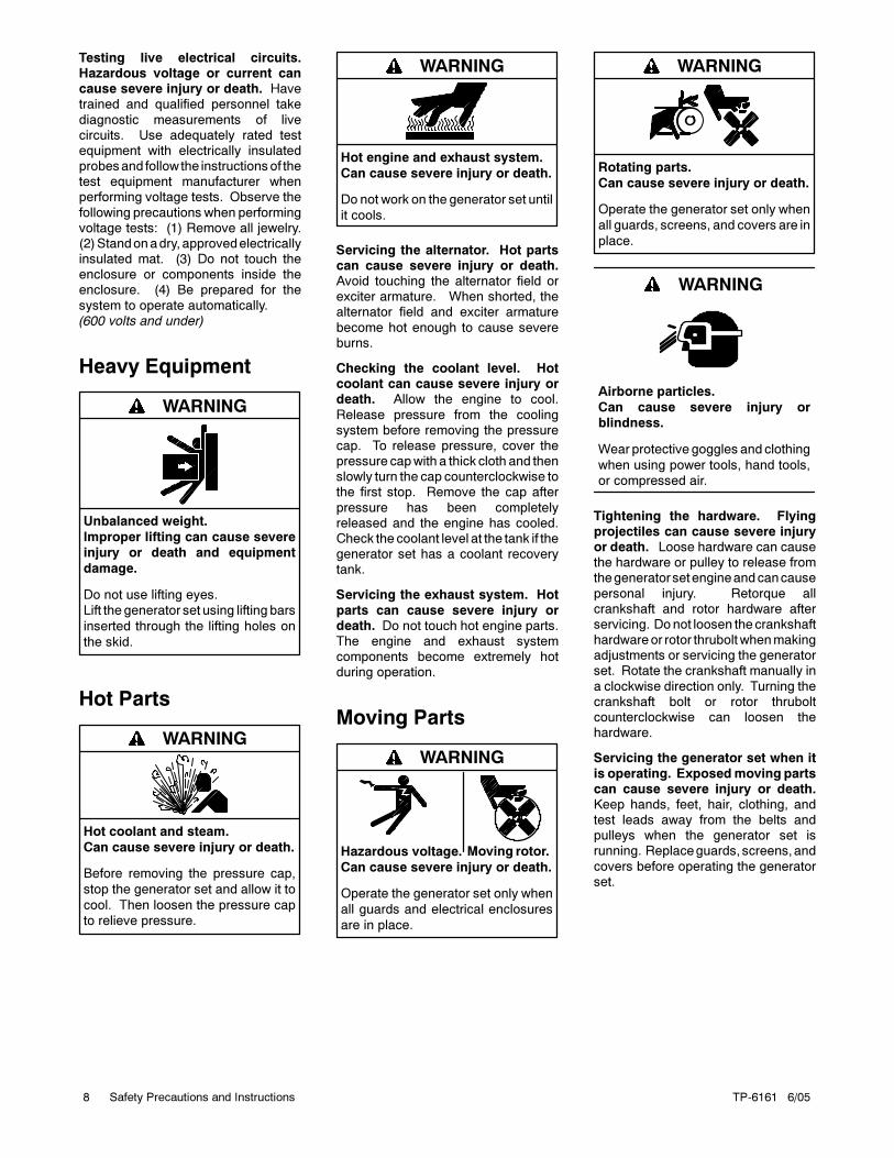
Moving Parts
Hazardous voltage.
Can cause severe injury or death.
Operate the generator set only when
all guards and electrical enclosures
are in place.
Moving rotor.
WARNING
Rotating parts.
Can cause severe injury or death.
Operate the generator set only when
all guards, screens, and covers are in
place.
WARNING
Airborne particles.
Can cause severe injury or
blindness.
Wear protective goggles and clothing
when using power tools, hand tools,
or compressed air.
WARNING
Tightening the hardware. Flyingprojectiles can cause severe injuryor death. Loose hardware can causethe hardware or pulley to release fromthegeneratorsetengineandcancause
personal injury. Retorque allcrankshaft and rotor hardware afterservicing. Donot loosen thecrankshafthardwareor rotor thrubolt whenmakingadjustments or servicing the generatorset. Rotate the crankshaft manually in
a clockwise direction only. Turning thecrankshaft bolt or rotor thruboltcounterclockwise can loosen thehardware.
Servicing the generator set when it
is operating. Exposedmoving partscan cause severe injury or death.Keep hands, feet, hair, clothing, andtest leads away from the belts andpulleys when the generator set isrunning. Replaceguards, screens,and
covers before operating the generatorset.
TP-6161 6/05 9Safety Precautions and Instructions
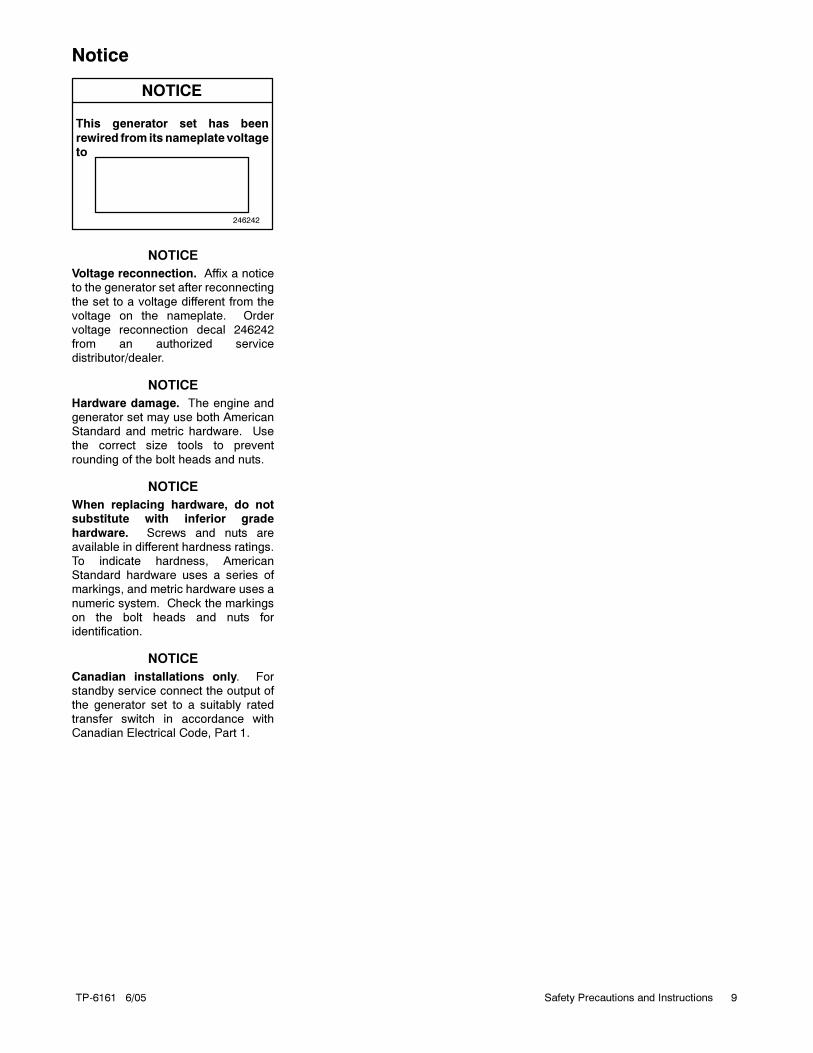
Notice
NOTICE
This generator set has been
rewired from its nameplate voltage
to
246242
NOTICE
Voltage reconnection. Affix a noticeto the generator set after reconnecting
the set to a voltage different from thevoltage on the nameplate. Ordervoltage reconnection decal 246242from an authorized servicedistributor/dealer.
NOTICE
Hardware damage. The engine andgenerator set may use both AmericanStandard and metric hardware. Usethe correct size tools to prevent
rounding of the bolt heads and nuts.
NOTICE
When replacing hardware, do notsubstitute with inferior grade
hardware. Screws and nuts areavailable in different hardness ratings.To indicate hardness, AmericanStandard hardware uses a series ofmarkings, and metric hardware uses a
numeric system. Check the markingson the bolt heads and nuts foridentification.
NOTICE
Canadian installations only. Forstandby service connect the output ofthe generator set to a suitably ratedtransfer switch in accordance withCanadian Electrical Code, Part 1.

TP-6161 6/0510 Safety Precautions and Instructions
Notes
TP-6161 6/05 11Introduction
Introduction
This manual provides operation instructions for
20--2000 kW generator sets equipped with the following
controllers:
Decision-Maker™ 3+, 16-Light
Decision-Maker™ 1
Wiring diagrammanuals are available separately. Refer
to the engine operation manual for generator set engine
scheduled maintenance information.
Information in this publication represents data available
at the time of print. Kohler Co. reserves the right to
change this publication and the products represented
without notice and without any obligation or liability
whatsoever.
Read this manual and carefully follow all procedures
and safety precautions to ensure proper equipment
operation and to avoid bodily injury. Read and follow the
Safety Precautions and Instructions section at the
beginning of this manual. Keep this manual with the
equipment for future reference.
The equipment service requirements are very important
to safe and efficient operation. Inspect the parts often
and perform required service at the prescribed intervals.
Maintenance work must be performed by appropriately
skilled and suitably trained maintenance personnel
familiar with generator set operation and service.
Abbreviations
This publication makes use of numerous abbreviations.
Typically, the word(s) are spelled out along with the
abbreviation in parentheses when shown for the first
time in a section. Appendix A, Abbreviations, also
includes many abbreviation definitions.
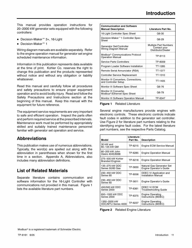
List of Related Materials
Separate literature contains communication and
software information for the 16-Light Controller with
communications not provided in this manual. Figure 1
lists the available literature part numbers.
Communication and Software
Manual Description Literature Part No.
16-Light Controller Spec Sheet G6-30
Decision-Maker1 Controller SpecSheet G6-29
Generator Set/ControllerWiring Diagram Manual
Multiple Part NumbersContact your
Distributor/Dealer
Modbus Communications ProtocolOperation Manual TP-6113
Service Parts Controllers TP-6009
Program Loader Software Installation TT-1285
Remote Serial Annunciator (RSA) TT-1377
Controller Service Replacement TT-1310
Monitor III Converters, Connections,and Controller Setup TT-1405
Monitor III Software Spec Sheet G6-76
Monitor III Converter,Modbus/Ethernet Spec Sheet G6-79
Monitor III Software Operation Manual TP-6347
Figure 1 Related Literature
Several engine manufacturers provide engines with
electronic controls. These electronic controls indicate
fault codes in addition to the generator set controller.
Use Figure 2 for literature part numbers relating to the
identifying engine fault codes. For the latest literature
part numbers, see the respective Parts Catalog.
Model
Literature
Part No. Description
30 kW and80--125 kW GM TP-6215 Engine ECM Service Manual
80--200 kW JohnDeere 4045/6068 TP-6285 Engine Operation Manual
275--500 kW KohlerBranded Engines TP-6218 Engine Operation Manual
135--275 kW DDCSeries 50/60 Gas TP-5830
Natural Gas Generator SetEngine Operator’s Guide
230--450 kW DDCSeries 60 TP-6056
DDEC IV Application andInstallation Manual
230--450 kW DDCSeries 60 TP-5611 Engine Operator’s Guide
450/500 kW DDCSeries 2000 TP-6361
DDEC IV ECMTroubleshooting Guide
650--1000 kW DDCSeries 2000 TP-6375
Engine OperatingInstructions (MDEC)
1350--2000 kWDDC/MTU Series 4000 TP-6237
Engine OperatingInstructions (MDEC)
Figure 2 Related Engine Literature
Modbus is a registered trademark of Schneider Electric.
TP-6161 6/0512 Service Assistance
Service Assistance
For professional advice on generator set power
requirements and conscientious service, please contact
your nearest Kohler distributor or dealer.
Consult the Yellow Pages under the heading
Generators—Electric
Visit the Kohler Power Systems website at
KohlerPowerSystems.com
Look at the labels and stickers on your Kohler product
or review the appropriate literature or documents
included with the product
Call toll free in the US and Canada 1-800-544-2444
Outside the US andCanada, call the nearest regional
office
Headquarters Europe, Middle East, Africa
(EMEA)
Kohler Power Systems
ZI Senia 122
12, rue des Hauts Flouviers
94517 Thiais Cedex
France
Phone: (33) 1 41 735500
Fax: (33) 1 41 735501
Asia Pacific
Power Systems Asia Pacific Regional Office
Singapore, Republic of Singapore
Phone: (65) 6264-6422
Fax: (65) 6264-6455
China
North China Regional Office, Beijing
Phone: (86) 10 6518 7950
(86) 10 6518 7951
(86) 10 6518 7952
Fax: (86) 10 6518 7955
East China Regional Office, Shanghai
Phone: (86) 21 6288 0500
Fax: (86) 21 6288 0550
India, Bangladesh, Sri Lanka
India Regional Office
Bangalore, India
Phone: (91) 80 3366208
(91) 80 3366231
Fax: (91) 80 3315972
Japan, Korea
North Asia Regional Office
Tokyo, Japan
Phone: (813) 3440-4515
Fax: (813) 3440-2727
Latin America
Latin America Regional Office
Lakeland, Florida, USA
Phone: (863) 619-7568
Fax: (863) 701-7131
TP-6161 6/05 13Section 1 Specifications and Features
Section 1 Specifications and Features
1.1 Introduction
The specification sheets for each generator set provide
specific generator and engine information. Refer to the
respective specification sheet for data not supplied in
this manual. Consult the generator set service manual,
installation manual, engine operation manual, and
engine service manual for additional specifications.
1.2 16-Light Controller Features
The 16-light controller can operate in either the normal
mode or the prime powermode. The prime powermode
allows reduced controller current draw in applications
without a battery charger, minimizing battery drain by
the controller circuitry. See Section 2.3.2, Prime Power
Mode Operation, for more information.
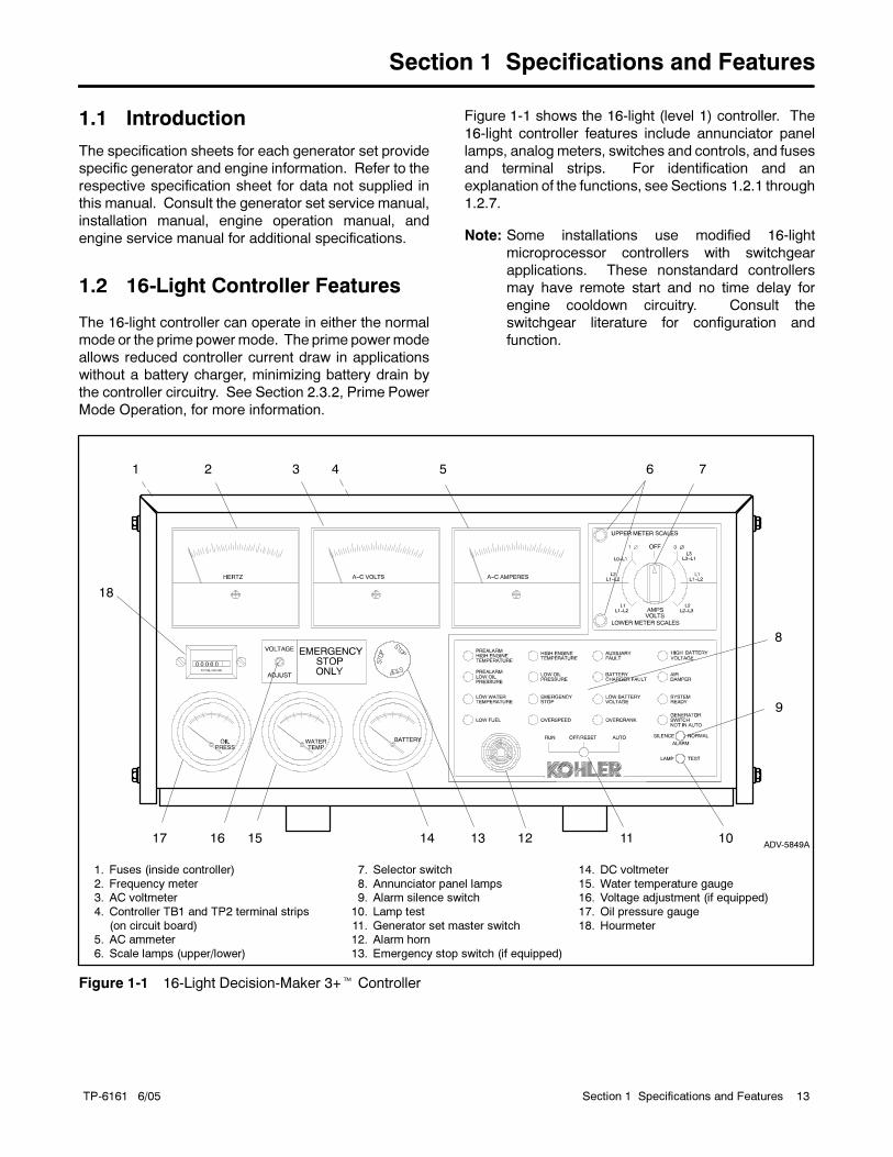
Figure 1-1 shows the 16-light (level 1) controller. The
16-light controller features include annunciator panel
lamps, analog meters, switches and controls, and fuses
and terminal strips. For identification and an
explanation of the functions, see Sections 1.2.1 through
1.2.7.
Note: Some installations use modified 16-light
microprocessor controllers with switchgear
applications. These nonstandard controllers
may have remote start and no time delay for
engine cooldown circuitry. Consult the
switchgear literature for configuration and
function.
1. Fuses (inside controller)
2. Frequency meter3. AC voltmeter
4. Controller TB1 and TP2 terminal strips
(on circuit board)5. AC ammeter
6. Scale lamps (upper/lower)
ADV-5849A
1 2 3 4 5 6 7
8
10111214 13151617
18
9
∅∅ ∅
7. Selector switch
8. Annunciator panel lamps9. Alarm silence switch
10. Lamp test
11. Generator set master switch12. Alarm horn
13. Emergency stop switch (if equipped)
14. DC voltmeter
15. Water temperature gauge16. Voltage adjustment (if equipped)
17. Oil pressure gauge
18. Hourmeter
Figure 1-1 16-Light Decision-Maker 3+ Controller
TP-6161 6/0514 Section 1 Specifications and Features
The 16-light controller with communications has a new
circuit board GM28725 that is different in appearance
and has additional functions from the earlier versions
but is a direct replacement for earlier version circuit
boards including A-336415. Features of the new
circuit board include the following items:
Red circuit board, previous versions are green.
Terminal strips (TB1, TB2, and TB3).
SW1 DIP switch (8 switches).
Communication connector P21 for Modbus to
download new application program software or to
connect the remote serial annunciator using RS-485
communications. Requires RS-485 to RS-232
converter for downloading application program.
Communication connector P22 for J1939 engine
communication.
New Application Program Software. Contact your
local authorized distributor for application program
updateswhen instructed to do so during troubleshooting
and/or when adding specific accessories. Refer to
TT--1285 Program Loader Software instruction for
additional download information.
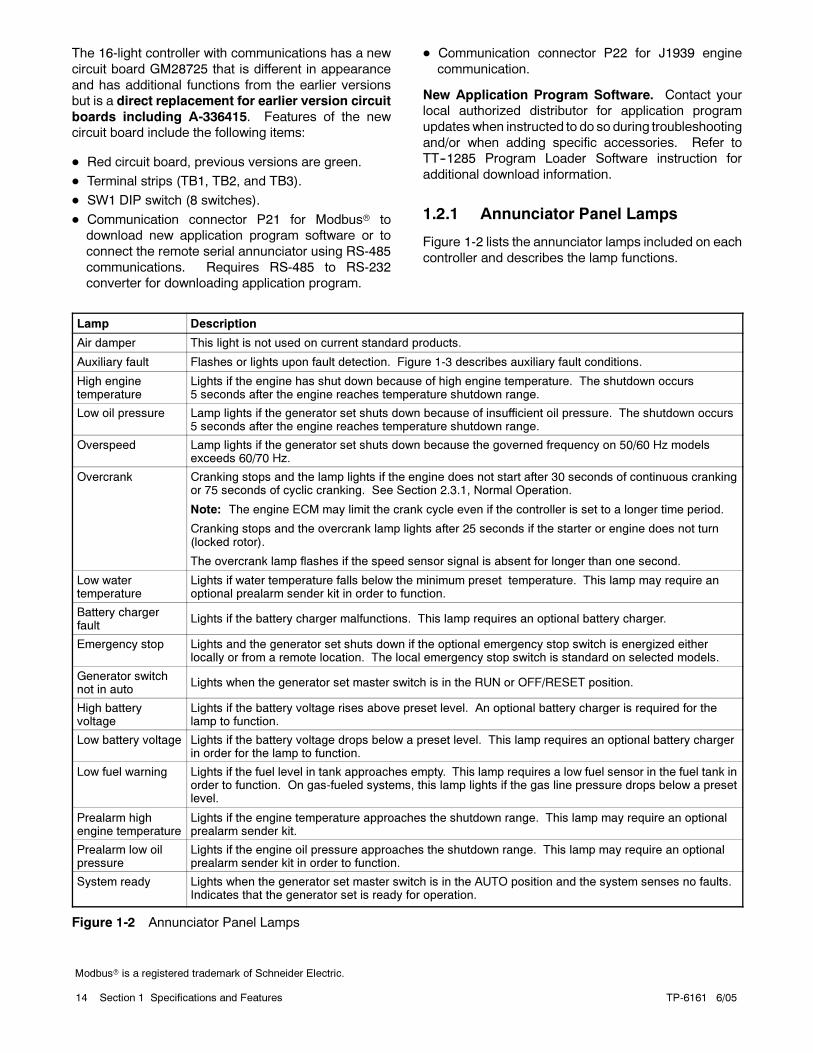
1.2.1 Annunciator Panel Lamps
Figure 1-2 lists the annunciator lamps included on each
controller and describes the lamp functions.
Lamp Description
Air damper This light is not used on current standard products.
Auxiliary fault Flashes or lights upon fault detection. Figure 1-3 describes auxiliary fault conditions.
High enginetemperature
Lights if the engine has shut down because of high engine temperature. The shutdown occurs5 seconds after the engine reaches temperature shutdown range.
Low oil pressure Lamp lights if the generator set shuts down because of insufficient oil pressure. The shutdown occurs5 seconds after the engine reaches temperature shutdown range.
Overspeed Lamp lights if the generator set shuts down because the governed frequency on 50/60 Hz modelsexceeds 60/70 Hz.
Overcrank Cranking stops and the lamp lights if the engine does not start after 30 seconds of continuous crankingor 75 seconds of cyclic cranking. See Section 2.3.1, Normal Operation.
Note: The engine ECM may limit the crank cycle even if the controller is set to a longer time period.
Cranking stops and the overcrank lamp lights after 25 seconds if the starter or engine does not turn(locked rotor).
The overcrank lamp flashes if the speed sensor signal is absent for longer than one second.
Low watertemperature
Lights if water temperature falls below the minimum preset temperature. This lamp may require anoptional prealarm sender kit in order to function.
Battery chargerfault
Lights if the battery charger malfunctions. This lamp requires an optional battery charger.
Emergency stop Lights and the generator set shuts down if the optional emergency stop switch is energized eitherlocally or from a remote location. The local emergency stop switch is standard on selected models.
Generator switchnot in auto
Lights when the generator set master switch is in the RUN or OFF/RESET position.
High batteryvoltage
Lights if the battery voltage rises above preset level. An optional battery charger is required for thelamp to function.
Low battery voltage Lights if the battery voltage drops below a preset level. This lamp requires an optional battery chargerin order for the lamp to function.
Low fuel warning Lights if the fuel level in tank approaches empty. This lamp requires a low fuel sensor in the fuel tank inorder to function. On gas-fueled systems, this lamp lights if the gas line pressure drops below a presetlevel.
Prealarm highengine temperature
Lights if the engine temperature approaches the shutdown range. This lamp may require an optionalprealarm sender kit.
Prealarm low oilpressure
Lights if the engine oil pressure approaches the shutdown range. This lamp may require an optionalprealarm sender kit in order to function.
System ready Lights when the generator set master switch is in the AUTO position and the system senses no faults.Indicates that the generator set is ready for operation.
Figure 1-2 Annunciator Panel Lamps
Modbus is a registered trademark of Schneider Electric.
TP-6161 6/05 15Section 1 Specifications and Features
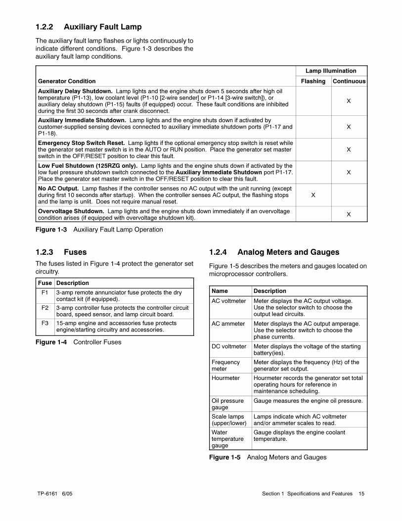
1.2.2 Auxiliary Fault Lamp
The auxiliary fault lamp flashes or lights continuously to
indicate different conditions. Figure 1-3 describes the
auxiliary fault lamp conditions.
Lamp Illumination
Generator Condition Flashing Continuous
Auxiliary Delay Shutdown. Lamp lights and the engine shuts down 5 seconds after high oiltemperature (P1-13), low coolant level (P1-10 [2-wire sender] or P1-14 [3-wire switch]), orauxiliary delay shutdown (P1-15) faults (if equipped) occur. These fault conditions are inhibitedduring the first 30 seconds after crank disconnect.
X
Auxiliary Immediate Shutdown. Lamp lights and the engine shuts down if activated bycustomer-supplied sensing devices connected to auxiliary immediate shutdown ports (P1-17 andP1-18).
X
Emergency Stop Switch Reset. Lamp lights if the optional emergency stop switch is reset whilethe generator set master switch is in the AUTO or RUN position. Place the generator set masterswitch in the OFF/RESET position to clear this fault.
X
Low Fuel Shutdown (125RZG only). Lamp lights and the engine shuts down if activated by thelow fuel pressure shutdown switch connected to the Auxiliary Immediate Shutdown port P1-17.Place the generator set master switch in the OFF/RESET position to clear this fault.
X
No AC Output. Lamp flashes if the controller senses no AC output with the unit running (exceptduring first 10 seconds after startup). When the controller senses AC output, the flashing stopsand the lamp is unlit. Does not require manual reset.
X
Overvoltage Shutdown. Lamp lights and the engine shuts down immediately if an overvoltagecondition arises (if equipped with overvoltage shutdown kit).
X
Figure 1-3 Auxiliary Fault Lamp Operation
1.2.3 Fuses
The fuses listed in Figure 1-4 protect the generator set
circuitry.
Fuse Description
F1 3-amp remote annunciator fuse protects the drycontact kit (if equipped).
F2 3-amp controller fuse protects the controller circuitboard, speed sensor, and lamp circuit board.
F3 15-amp engine and accessories fuse protectsengine/starting circuitry and accessories.
Figure 1-4 Controller Fuses
1.2.4 Analog Meters and Gauges
Figure 1-5 describes the meters and gauges located on
microprocessor controllers.
Name Description
AC voltmeter Meter displays the AC output voltage.Use the selector switch to choose theoutput lead circuits.
AC ammeter Meter displays the AC output amperage.Use the selector switch to choose thephase currents.
DC voltmeter Meter displays the voltage of the startingbattery(ies).
Frequencymeter
Meter displays the frequency (Hz) of thegenerator set output.
Hourmeter Hourmeter records the generator set totaloperating hours for reference inmaintenance scheduling.
Oil pressuregauge
Gauge measures the engine oil pressure.
Scale lamps(upper/lower)
Lamps indicate which AC voltmeterand/or ammeter scales to read.
Watertemperaturegauge
Gauge displays the engine coolanttemperature.
Figure 1-5 Analog Meters and Gauges
TP-6161 6/0516 Section 1 Specifications and Features
1.2.5 Switches and Controls
Figure 1-6 describes the switches and controls located
on microprocessor controllers.
Name Description
Alarm horn Horn sounds if any fault or prealarmcondition exists (except emergency stop,battery charger fault, high battery voltage, orlow battery voltage). Place the generator setmaster switch in the AUTO position beforesilencing the alarm horn. See controllerresetting procedure in Section 2.3.5,Controller Resetting After a Fault Shutdown.
Alarmsilenceswitch
Switch silences the alarm during service.Place the generator set master switch in theAUTO position before silencing the alarmhorn. To avoid reactivating the alarm horn,restore all alarm horn switches (controller,remote annunciator, and audiovisual alarm)to their normal positions after correcting thefault. See controller resetting procedure inSection 2.3.5, Controller Resetting After aFault Shutdown.
Emergencystop switch
Switch (if equipped) immediately shuts downthe generator set in emergency situations.Reset the emergency stop switch aftershutdown by rotating the switch clockwise.Use the emergency stop switch foremergency shutdowns only. Use thegenerator set master switch for normalshutdowns. The local emergency stopswitch is standard on selected generatorsets.
Generatorset masterswitch
Switch functions as the controller reset andgenerator set operation switch. Refer toSection 2.3.1, Normal Operation, Section2.3.2, Prime Power Mode Operation, andSection 2.3.5, Controller Resetting After aFault Shutdown.
Lamp testswitch
Switch displays the controller indicatorlamps.
Selectorswitch
Switch selects the generator set outputcircuits to measure. When switched to aposition with three circuit labels, the metersdisplay the amperage on the lead shown inthe upper label and the voltage between thetwo leads shown in the lower label. The ACammeter and voltmeter function only withthe switch in the ON position.
Voltageadjustmentcontrol, ifequipped
Control fine tunes (±5%) the generator setoutput voltage. Used with 20--400 kWpermanent magnet/wound field alternatormodels only. The voltage adjustment on350--2000 kW pilot-excited models is locatedin the generator junction box.
Figure 1-6 Switches and Controls
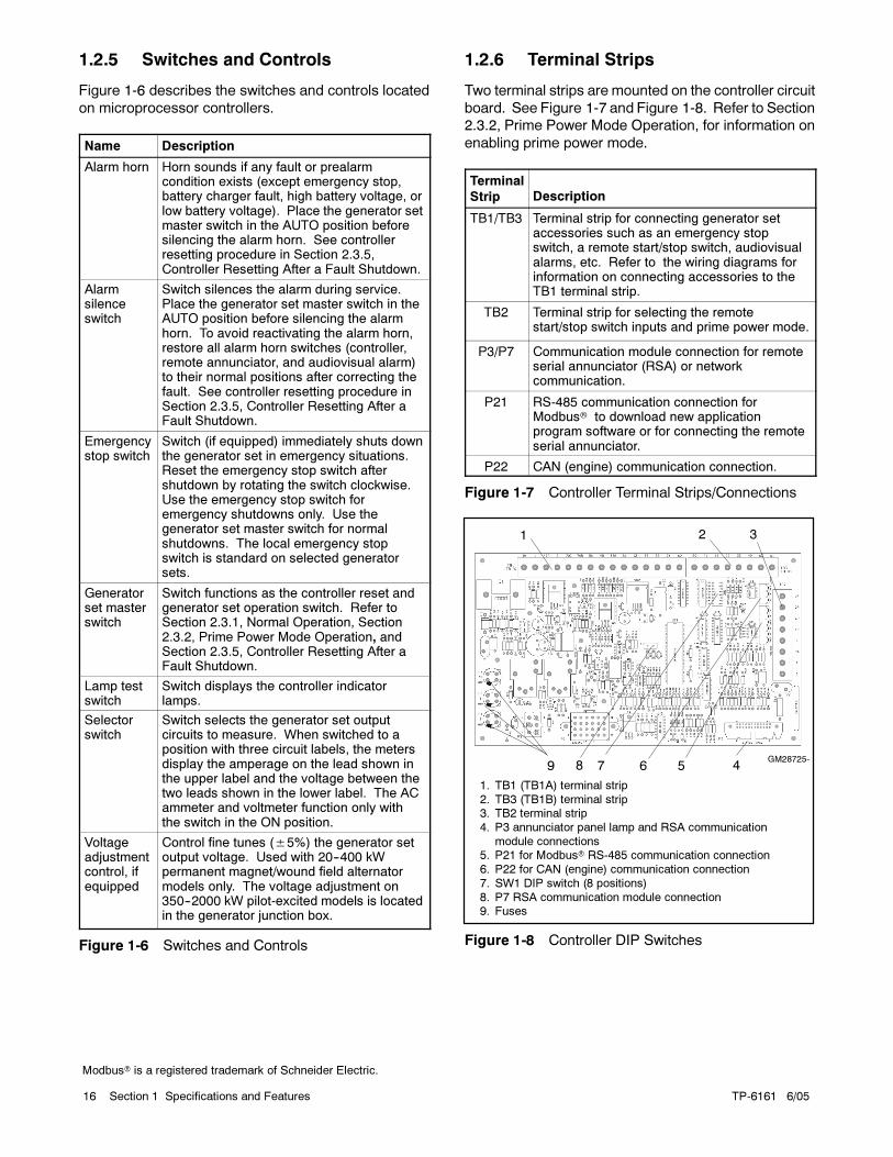
1.2.6 Terminal Strips
Two terminal strips are mounted on the controller circuit
board. See Figure 1-7 and Figure 1-8. Refer to Section
2.3.2, Prime Power Mode Operation, for information on
enabling prime power mode.
Terminal
Strip Description
TB1/TB3 Terminal strip for connecting generator setaccessories such as an emergency stopswitch, a remote start/stop switch, audiovisualalarms, etc. Refer to the wiring diagrams forinformation on connecting accessories to theTB1 terminal strip.
TB2 Terminal strip for selecting the remotestart/stop switch inputs and prime power mode.
P3/P7 Communication module connection for remoteserial annunciator (RSA) or networkcommunication.
P21 RS-485 communication connection forModbus to download new applicationprogram software or for connecting the remoteserial annunciator.
P22 CAN (engine) communication connection.
Figure 1-7 Controller Terminal Strips/Connections
1. TB1 (TB1A) terminal strip
2. TB3 (TB1B) terminal strip3. TB2 terminal strip
4. P3 annunciator panel lamp and RSA communication
module connections5. P21 for Modbus RS-485 communication connection
6. P22 for CAN (engine) communication connection
7. SW1 DIP switch (8 positions)
8. P7 RSA communication module connection9. Fuses
GM28725-569 7
2 31
48
Figure 1-8 Controller DIP Switches
Modbus is a registered trademark of Schneider Electric.
TP-6161 6/05 17Section 1 Specifications and Features
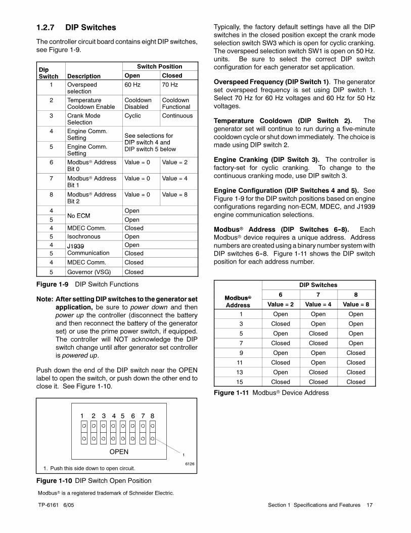
1.2.7 DIP Switches
The controller circuit board contains eight DIP switches,
see Figure 1-9.
DipSwitch Position
DipSwitch Description Open Closed
1 Overspeedselection
60 Hz 70 Hz
2 TemperatureCooldown Enable
CooldownDisabled
CooldownFunctional
3 Crank ModeSelection
Cyclic Continuous
4 Engine Comm.Setting See selections for
DIP switch 4 and5 Engine Comm.
Setting
DIP switch 4 andDIP switch 5 below
6 Modbus AddressBit 0
Value = 0 Value = 2
7 Modbus AddressBit 1
Value = 0 Value = 4
8 Modbus AddressBit 2
Value = 0 Value = 8
4N ECM
Open
5No ECM
Open
4 MDEC Comm. Closed
5 Isochronous Open
4 J1939 Open
5J1939Communication Closed
4 MDEC Comm. Closed
5 Governor (VSG) Closed
Figure 1-9 DIP Switch Functions
Note: After settingDIP switches to thegenerator set
application, be sure to power down and then
power up the controller (disconnect the battery
and then reconnect the battery of the generator
set) or use the prime power switch, if equipped.
The controller will NOT acknowledge the DIP
switch change until after generator set controller
is powered up.
Push down the end of the DIP switch near the OPEN
label to open the switch, or push down the other end to
close it. See Figure 1-10.
6126
1. Push this side down to open circuit.
OPEN
1 2 3
1
4 5 6 7 8
Figure 1-10 DIP Switch Open Position
Typically, the factory default settings have all the DIP
switches in the closed position except the crank mode
selection switch SW3 which is open for cyclic cranking.
The overspeed selection switch SW1 is open on 50 Hz.
units. Be sure to select the correct DIP switch
configuration for each generator set application.
Overspeed Frequency (DIP Switch 1). The generator
set overspeed frequency is set using DIP switch 1.
Select 70 Hz for 60 Hz voltages and 60 Hz for 50 Hz
voltages.
Temperature Cooldown (DIP Switch 2). The
generator set will continue to run during a five-minute
cooldown cycle or shut down immediately. The choice is
made using DIP switch 2.
Engine Cranking (DIP Switch 3). The controller is
factory-set for cyclic cranking. To change to the
continuous cranking mode, use DIP switch 3.
Engine Configuration (DIP Switches 4 and 5). See
Figure 1-9 for the DIP switch positions based on engine
configurations regarding non-ECM, MDEC, and J1939
engine communication selections.
Modbus Address (DIP Switches 6--8). Each
Modbus device requires a unique address. Address
numbers are created using a binary number systemwith
DIP switches 6--8. Figure 1-11 shows the DIP switch
position for each address number.
DIP Switches
Modbus6 7 8
Modbus
Address Value = 2 Value = 4 Value = 8
1 Open Open Open
3 Closed Open Open
5 Open Closed Open
7 Closed Closed Open
9 Open Open Closed
11 Closed Open Closed
13 Open Closed Closed
15 Closed Closed Closed
Figure 1-11 Modbus Device Address
Modbus is a registered trademark of Schneider Electric.
TP-6161 6/0518 Section 1 Specifications and Features
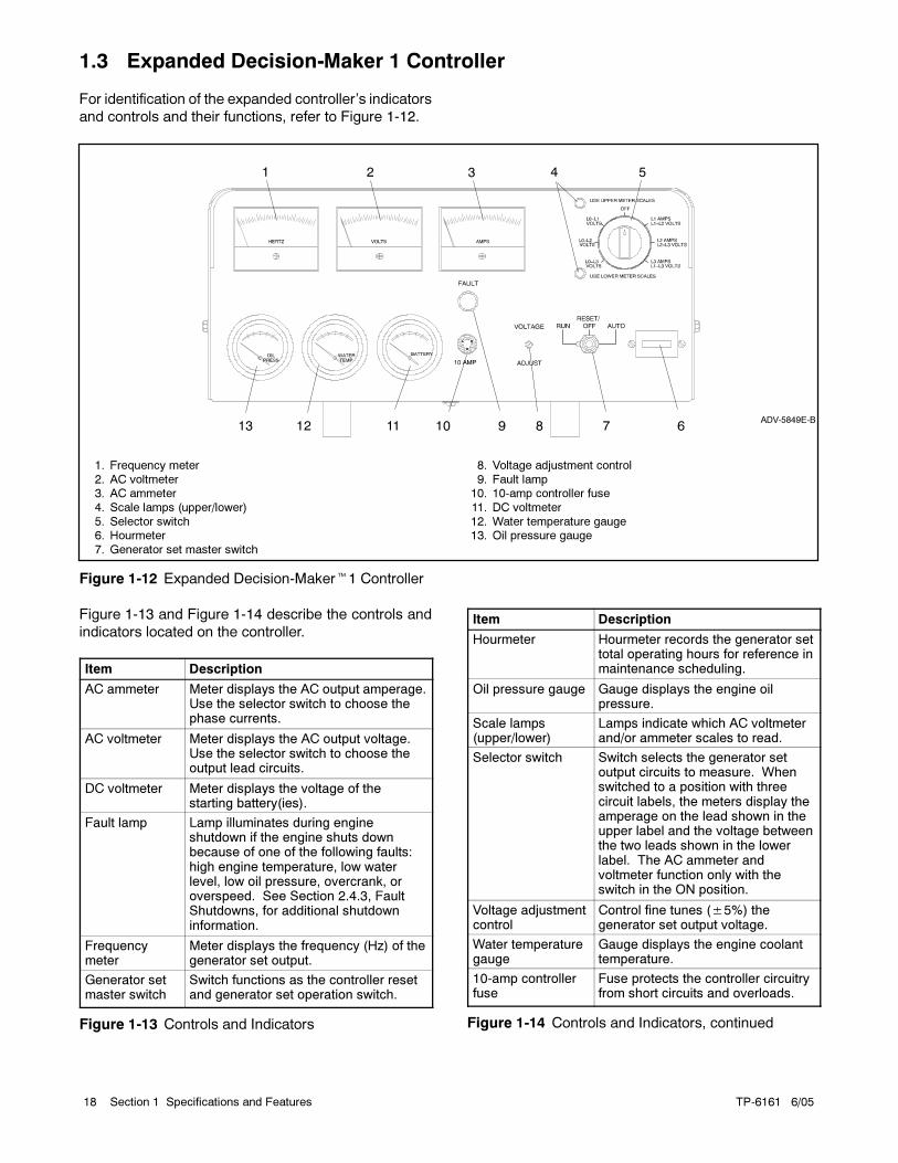
1.3 Expanded Decision-Maker 1 Controller
For identification of the expanded controller’s indicators
and controls and their functions, refer to Figure 1-12.
1
10111213ADV-5849E-B
789
2 3 4 5
6
1. Frequency meter
2. AC voltmeter3. AC ammeter
4. Scale lamps (upper/lower)
5. Selector switch6. Hourmeter
7. Generator set master switch
8. Voltage adjustment control
9. Fault lamp10. 10-amp controller fuse
11. DC voltmeter
12. Water temperature gauge13. Oil pressure gauge
Figure 1-12 Expanded Decision-Maker1 Controller
Figure 1-13 and Figure 1-14 describe the controls and
indicators located on the controller.
Item Description
AC ammeter Meter displays the AC output amperage.Use the selector switch to choose thephase currents.
AC voltmeter Meter displays the AC output voltage.Use the selector switch to choose theoutput lead circuits.
DC voltmeter Meter displays the voltage of thestarting battery(ies).
Fault lamp Lamp illuminates during engineshutdown if the engine shuts downbecause of one of the following faults:high engine temperature, low waterlevel, low oil pressure, overcrank, oroverspeed. See Section 2.4.3, FaultShutdowns, for additional shutdowninformation.
Frequencymeter
Meter displays the frequency (Hz) of thegenerator set output.
Generator setmaster switch
Switch functions as the controller resetand generator set operation switch.
Figure 1-13 Controls and Indicators
Item Description
Hourmeter Hourmeter records the generator settotal operating hours for reference inmaintenance scheduling.
Oil pressure gauge Gauge displays the engine oilpressure.
Scale lamps(upper/lower)
Lamps indicate which AC voltmeterand/or ammeter scales to read.
Selector switch Switch selects the generator setoutput circuits to measure. Whenswitched to a position with threecircuit labels, the meters display theamperage on the lead shown in theupper label and the voltage betweenthe two leads shown in the lowerlabel. The AC ammeter andvoltmeter function only with theswitch in the ON position.
Voltage adjustmentcontrol
Control fine tunes (±5%) thegenerator set output voltage.
Water temperaturegauge
Gauge displays the engine coolanttemperature.
10-amp controllerfuse
Fuse protects the controller circuitryfrom short circuits and overloads.
Figure 1-14 Controls and Indicators, continued
TP-6161 6/05 19Section 2 Operation
Section 2 Operation
2.1 Prestart Checklist
To ensure continued satisfactory operation, perform the
following checks or inspections before or at each
startup, as designated, and at the intervals specified in
the service schedule. In addition, some checks require
verification after the unit starts.
Air Cleaner. Check for a clean and installed air cleaner
element to prevent unfiltered air from entering the
engine.
Battery. Check for tight battery connections. Consult
the battery manufacturer’s instructions regarding
battery care and maintenance.
Coolant Level. Check the coolant level according to
the cooling system maintenance information.
Note: Block heater damage. The block heater will fail
if the energized heater element is not immersed
in coolant. Fill the cooling system before turning
on the block heater. Run the engine until it is
warm, and refill the radiator to purge the air from
the system before energizing the block heater.
Drive Belts. Check the belt condition and tension of the
radiator fan, water pump, and battery charging
alternator belt(s).
Exhaust System. Check for exhaust leaks and
blockages. Check the silencer and piping condition and
check for tight exhaust system connections.
Inspect the exhaust system components (exhaust
manifold, exhaust line, flexible exhaust, clamps,
silencer, and outlet pipe) for cracks, leaks, and
corrosion.
Check for corroded or brokenmetal parts and replace
them as needed.
Check for loose, corroded, or missing clamps and
hangers. Tighten or replace the exhaust clamps and/
or hangers as needed.
Check that the exhaust outlet is unobstructed.
Visually inspect for exhaust leaks (blowby). Check
for carbon or soot residue on exhaust components.
Carbon and soot residue indicates an exhaust leak.
Seal leaks as needed.
Fuel Level. Check the fuel level and fill the tank(s)
regularly to ensure adequate fuel supply.
Lamp Test. Press the lamp test button, if equipped, to
verify that all controller LEDs illuminate.
Oil Level. Maintain the oil level at or near, not over, the
full mark on the dipstick. Keep the oil level in the
mechanical governor, if equipped, at or near the full
level.
Operating Area. Check for obstructions that could
block the flow of cooling air. Keep the air intake area
clean. Do not leave rags, tools, or debris on or near the
generator set.
2.2 Generator Set Exercising
Operate the generator set under load once each week
for one hour. Perform the exercise in the presence of an
operator if the generator set does not have a
programmed exercise mode or an automatic transfer
switch with an exercise option.
During the exercise period apply aminimumof 35% load
based on the nameplate standby rating, unless
otherwise instructed in the engine operation manual.
The operator should perform all of the prestart checks
before starting the exercise procedure. Start the
generator set according to the starting procedure in the
controller section of this manual. While the generator
set is operating, listen for a smooth-running engine and
visually inspect the generator set for fluid or exhaust
leaks.
2.3 16-Light Controller Features
2.3.1 Normal Operation
Local Starting. Move the generator set master switch
to the RUN position to start the generator set at the
controller.
Note: The alarm horn sounds and the Not in Auto lamp
lights when the generator set master switch is not
in the AUTO position.
Note: The transient start/stop function of the16-light
controller prevents accidental cranking of the
rotating engine. If the generator set master
switch is momentarily placed in the OFF/RESET
position and then is returned to the RUN position,
the generator set slows to 750 rpm (25 Hz) and
recranks before returning to rated speed.
TP-6161 6/0520 Section 2 Operation
Automatic Starting. Move the generator set master
switch to the AUTO position to allow startup by an
automatic transfer switch or a remote start/stop switch.
Refer to the wiring diagrams for remote switch
connection information.
The engine cranks up to 30 seconds continuously or
75 seconds cyclically (crank 15 seconds, rest 15 seconds,
crank 15 seconds, etc.) before shutting down on an
overcrank fault.
Note: The engine ECMmay limit the crank cycle even if
the controller is set to a longer time period.
Select the cyclic or continuous cranking mode on the
controller circuit board. See Section 1.2.7 DIP switches.
Stopping. Run the generator set without load for
5 minutes to ensure adequate engine cooldown. To
stop the generator set, place the generator set master
switch in the OFF/RESET position and wait until the
generator set stops completely.
Note: The generator set continues to run during a
5-minute cooldown cycle if a remote switch or
automatic transfer switch signals the engine to
stop.
Note: The controller circuit board DIP switches allow
disabling the engine cooldown function.
2.3.2 Prime Power Mode Operation
The controller can operate in either the normal mode or
the prime power mode. In prime power mode, the
controller draws less current when the generator set
master switch is in theOFF/RESET position, minimizing
the battery drain. Use the prime power mode for
installations that do not have a battery charger to help
prevent discharging the battery when the generator set
is not operating.
Moving the generator set master switch to the
OFF/RESET position disables all controller functions.
Moving the generator set master switch to the AUTO
position restores controller functions.
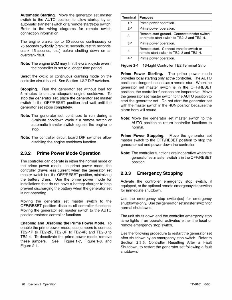
Enabling and Disabling the Prime Power Mode. To
enable the prime power mode, use jumpers to connect
TB2-1P to TB2-2P, TB2-3P to TB2-4P, and TB2-3 to
TB2-4. To deactivate the prime power mode, remove
these jumpers. See Figure 1-7, Figure 1-8, and
Figure 2-1.
Terminal Purpose
1P Prime power operation.
2P Prime power operation.
3Remote start ground. Connect transfer switchor remote start switch to TB2--3 and TB2--4.
3P Prime power operation.
4Remote start. Connect transfer switch orremote start switch to TB2--3 and TB2--4.
4P Prime power operation.
Figure 2-1 16-Light Controller TB2 Terminal Strip
Prime Power Starting. The prime power mode
provides local starting only at the controller. The AUTO
position no longer functions as a remote start. When the
generator set master switch is in the OFF/RESET
position, the controller functions are inoperative. Move
the generator set master switch to the AUTO position to
start the generator set. Do not start the generator set
with the master switch in the RUN position because the
alarm horn will sound.
Note: Move the generator set master switch to the
AUTO position to return controller functions to
normal.
Prime Power Stopping. Move the generator set
master switch to the OFF/RESET position to stop the
generator set and power down the controller.
Note: The controller functions are inoperative when the
generator setmaster switch is in theOFF/RESET
position.
2.3.3 Emergency Stopping
Activate the controller emergency stop switch, if
equipped, or the optional remote emergency stop switch
for immediate shutdown.
Use the emergency stop switch(es) for emergency
shutdowns only. Use thegenerator setmaster switch for
normal shutdowns.
The unit shuts down and the controller emergency stop
lamp lights if an operator activates either the local or
remote emergency stop switch.
Use the following procedure to restart the generator set
after shutdown by an emergency stop switch. Refer to
Section 2.3.5, Controller Resetting After a Fault
Shutdown, to restart the generator set following a fault
shutdown.
TP-6161 6/05 21Section 2 Operation
Emergency Stop Switch Resetting Procedure
1. Investigate the cause of the emergency stop and
correct the circuit or wiring problem(s).
2. If the remote emergency stop switch was activated,
reset the switch by replacing the glass piece. If the
controller-mounted emergency stop switch (if
equipped) was activated, reset the controller
emergency stop switch by rotating the switch
clockwise until it springs back to its original position.
Note: The controller auxiliary fault lamp lights if the
generator set master switch is in the RUN or
AUTO position during the resetting
procedure.
3. Toggle the generator set master switch to the
OFF/RESET position and then to the RUN or
AUTO position to restart the generator set. The
generator set does not crank until the resetting
procedure is completed.
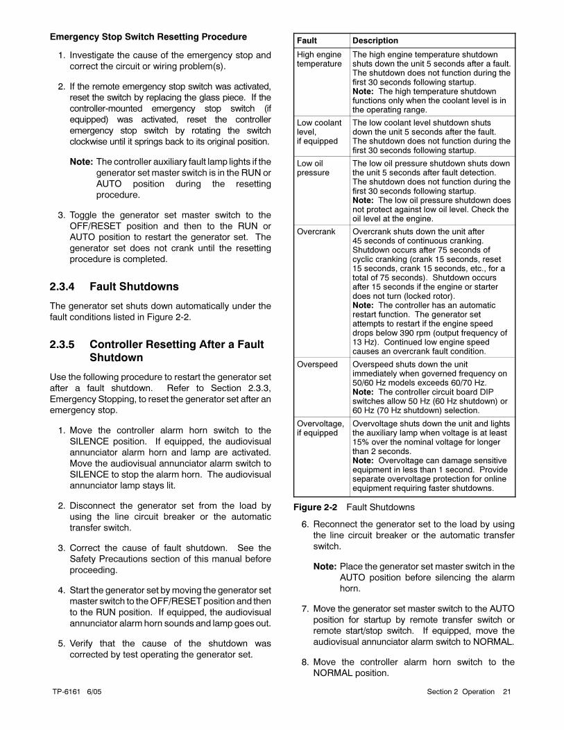
2.3.4 Fault Shutdowns
The generator set shuts down automatically under the
fault conditions listed in Figure 2-2.
2.3.5 Controller Resetting After a Fault
Shutdown
Use the following procedure to restart the generator set
after a fault shutdown. Refer to Section 2.3.3,
Emergency Stopping, to reset the generator set after an
emergency stop.
1. Move the controller alarm horn switch to the
SILENCE position. If equipped, the audiovisual
annunciator alarm horn and lamp are activated.
Move the audiovisual annunciator alarm switch to
SILENCE to stop the alarm horn. The audiovisual
annunciator lamp stays lit.
2. Disconnect the generator set from the load by
using the line circuit breaker or the automatic
transfer switch.
3. Correct the cause of fault shutdown. See the
Safety Precautions section of this manual before
proceeding.
4. Start the generator set bymoving the generator set
master switch to theOFF/RESETposition and then
to the RUN position. If equipped, the audiovisual
annunciator alarm horn sounds and lamp goes out.
5. Verify that the cause of the shutdown was
corrected by test operating the generator set.
Fault Description
High enginetemperature
The high engine temperature shutdownshuts down the unit 5 seconds after a fault.The shutdown does not function during thefirst 30 seconds following startup.Note: The high temperature shutdownfunctions only when the coolant level is inthe operating range.
Low coolantlevel,if equipped
The low coolant level shutdown shutsdown the unit 5 seconds after the fault.The shutdown does not function during thefirst 30 seconds following startup.
Low oilpressure
The low oil pressure shutdown shuts downthe unit 5 seconds after fault detection.The shutdown does not function during thefirst 30 seconds following startup.Note: The low oil pressure shutdown doesnot protect against low oil level. Check theoil level at the engine.
Overcrank Overcrank shuts down the unit after45 seconds of continuous cranking.Shutdown occurs after 75 seconds ofcyclic cranking (crank 15 seconds, reset15 seconds, crank 15 seconds, etc., for atotal of 75 seconds). Shutdown occursafter 15 seconds if the engine or starterdoes not turn (locked rotor).Note: The controller has an automaticrestart function. The generator setattempts to restart if the engine speeddrops below 390 rpm (output frequency of13 Hz). Continued low engine speedcauses an overcrank fault condition.
Overspeed Overspeed shuts down the unitimmediately when governed frequency on50/60 Hz models exceeds 60/70 Hz.Note: The controller circuit board DIPswitches allow 50 Hz (60 Hz shutdown) or60 Hz (70 Hz shutdown) selection.
Overvoltage,if equipped
Overvoltage shuts down the unit and lightsthe auxiliary lamp when voltage is at least15% over the nominal voltage for longerthan 2 seconds.Note: Overvoltage can damage sensitiveequipment in less than 1 second. Provideseparate overvoltage protection for onlineequipment requiring faster shutdowns.
Figure 2-2 Fault Shutdowns
6. Reconnect the generator set to the load by using
the line circuit breaker or the automatic transfer
switch.
Note: Place the generator set master switch in the
AUTO position before silencing the alarm
horn.
7. Move the generator set master switch to the AUTO
position for startup by remote transfer switch or
remote start/stop switch. If equipped, move the
audiovisual annunciator alarm switch to NORMAL.
8. Move the controller alarm horn switch to the
NORMAL position.
TP-6161 6/0522 Section 2 Operation
2.4 Expanded Decision-Maker 1
Controller
2.4.1 Generator Set Starting
Local Starting. Move the generator set to the RUN
position to immediately start the generator set.
Automatic Starting. Move the generator set master
switch to the AUTO position to allow startup by the
automatic transfer switch or the remote start/stop switch
connected to controller terminals TB1-3 and TB1-4.
Note: The controller allows up to 30 seconds of
continuous cranking before overcrank shutdown
occurs.
Note: The engine ECMmay limit the crank cycle even if
the controller is set to a longer time period.
2.4.2 Generator Set Stopping
Local Stopping
1. Run the generator set at no load for 5 minutes to
ensure adequate engine cooldown.
2. Move the generator set master switch to the
OFF/RESET position. The engine stops.
Automatic Stopping
1. The automatic transfer switch (ATS) or other
device disconnects the load from the generator set.
2. The generator set continues to run for a preset time
if the ATS is equipped with an engine cooldown
time delay.
3. The ATS opens the connection between controller
terminals TB1-3 and TB1-4. The generator set
shuts down if the generator set master switch is in
the AUTO position.
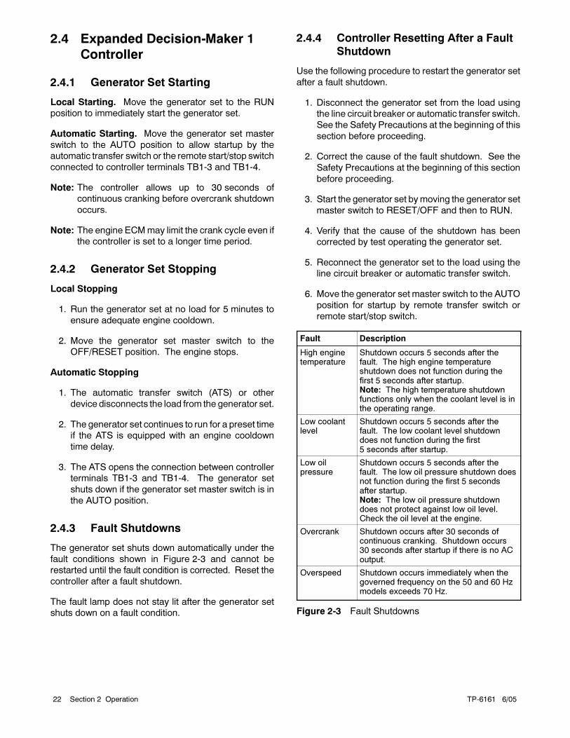
2.4.3 Fault Shutdowns
The generator set shuts down automatically under the
fault conditions shown in Figure 2-3 and cannot be
restarted until the fault condition is corrected. Reset the
controller after a fault shutdown.
The fault lamp does not stay lit after the generator set
shuts down on a fault condition.
2.4.4 Controller Resetting After a Fault
Shutdown
Use the following procedure to restart the generator set
after a fault shutdown.
1. Disconnect the generator set from the load using
the line circuit breaker or automatic transfer switch.
See the Safety Precautions at the beginning of this
section before proceeding.
2. Correct the cause of the fault shutdown. See the
Safety Precautions at the beginning of this section
before proceeding.
3. Start the generator set bymoving the generator set
master switch to RESET/OFF and then to RUN.
4. Verify that the cause of the shutdown has been
corrected by test operating the generator set.
5. Reconnect the generator set to the load using the
line circuit breaker or automatic transfer switch.
6. Move the generator set master switch to the AUTO
position for startup by remote transfer switch or
remote start/stop switch.
Fault Description
High enginetemperature
Shutdown occurs 5 seconds after thefault. The high engine temperatureshutdown does not function during thefirst 5 seconds after startup.Note: The high temperature shutdownfunctions only when the coolant level is inthe operating range.
Low coolantlevel
Shutdown occurs 5 seconds after thefault. The low coolant level shutdowndoes not function during the first5 seconds after startup.
Low oilpressure
Shutdown occurs 5 seconds after thefault. The low oil pressure shutdown doesnot function during the first 5 secondsafter startup.Note: The low oil pressure shutdowndoes not protect against low oil level.Check the oil level at the engine.
Overcrank Shutdown occurs after 30 seconds ofcontinuous cranking. Shutdown occurs30 seconds after startup if there is no ACoutput.
Overspeed Shutdown occurs immediately when thegoverned frequency on the 50 and 60 Hzmodels exceeds 70 Hz.
Figure 2-3 Fault Shutdowns
TP-6161 6/05 23Section 3 Scheduled Maintenance
Section 3 Scheduled Maintenance
Under normal operating conditions, the generator set’s
alternator requires no normal service. Consult the
prestart checklist in Section 2.1 for a list of routine
checks.
3.1 Alternator Service
When operating the generator set under dusty or dirty
conditions, use dry compressed air to blow dust out of
the alternator while the generator set is running. Direct
the stream of air through openings in the generator set
end bracket.
3.2 Engine Service
Perform engine service at the intervals specified in the
engine manufacturer’s service literature. Contact an
authorized service distributor/dealer to obtain service
literature.
Note: Have maintenance work, including battery
service, performed by appropriately skilled and
suitably trained maintenance personnel familiar
with generator set operation and service.
Accidental starting.Can cause severe injury or death.
Disconnect the battery cables beforeworking on the generator set.
Remove the negative (--) lead firstwhen disconnecting the battery.Reconnect the negative (--) lead lastwhen reconnecting the battery.
WARNING
Disabling the generator set. Accidental starting cancause severe injury or death. Before working on thegenerator set or connected equipment, disable the generatorset as follows: (1) Move thegenerator setmaster switch to the
OFFposition. (2) Disconnect thepower to thebattery charger.(3) Remove the battery cables, negative (--) lead first.Reconnect the negative (--) lead last when reconnecting thebattery. Follow these precautions to prevent starting of thegenerator set by an automatic transfer switch, remotestart/stop switch, or engine start command from a remote
computer.
Hot engine and exhaust system.
Can cause severe injury or death.
Do not work on the generator set until
it cools.
WARNING
Servicing the exhaust system. Hot parts can causesevere injury or death. Do not touch hot engine parts. Theengine and exhaust system components become extremelyhot during operation.
Hazardous voltage.
Can cause severe injury or death.
Operate the generator set only when
all guards and electrical enclosures
are in place.
Moving rotor.
WARNING
Servicing thegenerator setwhen it is operating. Exposedmoving parts can cause severe injury or death. Keephands, feet, hair, clothing, and test leads away from the beltsand pulleys when the generator set is running. Replace
guards, screens, and covers before operating the generatorset.
TP-6161 6/0524 Section 3 Scheduled Maintenance
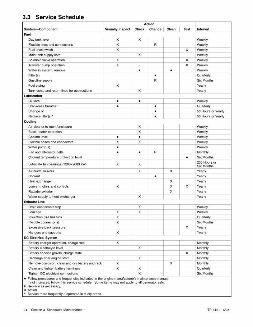
3.3 Service ScheduleAction
System—Component Visually Inspect Check Change Clean Test Interval
Fuel
Day tank level X X Weekly
Flexible lines and connections X R Weekly
Fuel level switch X X Weekly
Main tank supply level X Weekly
Solenoid valve operation X X Weekly
Transfer pump operation X X Weekly
Water in system, remove Weekly
Filter(s) Quarterly
Gasoline supply R Six Months
Fuel piping X Yearly
Tank vents and return lines for obstructions X Yearly
Lubrication
Oil level Weekly
Crankcase breather Quarterly
Change oil 50 Hours or Yearly
Replace filter(s)* 50 Hours or Yearly
Cooling
Air cleaner to room/enclosure X Weekly
Block heater operation X Weekly
Coolant level Weekly
Flexible hoses and connectors X X Weekly
Water pump(s) Weekly
Fan and alternator belts R Monthly
Coolant temperature protection level Six Months
Lubricate fan bearings (1200--2000 kW) X X200 Hours orSix Months
Air ducts, louvers X X Yearly
Coolant Yearly
Heat exchanger X Yearly
Louver motors and controls X X X Yearly
Radiator exterior X Yearly
Water supply to heat exchanger X Yearly
Exhaust Line
Drain condensate trap X Weekly
Leakage X X Weekly
Insulation, fire hazards X Quarterly
Flexible connector(s) X Six Months
Excessive back pressure X Yearly
Hangers and supports X Yearly
DC Electrical System
Battery charger operation, charge rate X Monthly
Battery electrolyte level X Monthly
Battery specific gravity, charge state X Monthly
Recharge after engine start X Monthly
Remove corrosion, clean and dry battery and rack X X Monthly
Clean and tighten battery terminals X X Quarterly
Tighten DC electrical connections X Six Months
Follow procedures and frequencies indicated in the engine manufacturer’s maintenance manual.If not indicated, follow this service schedule. Some items may not apply to all generator sets.
R Replace as necessary.X Action* Service more frequently if operated in dusty areas.
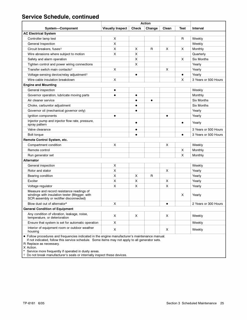
TP-6161 6/05 25Section 3 Scheduled Maintenance
Service Schedule, continuedAction
System—Component Visually Inspect Check Change Clean Test Interval
AC Electrical System
Controller lamp test X R Weekly
General Inspection X Weekly
Circuit breakers, fuses X X R X X Monthly
Wire abrasions where subject to motion X X Quarterly
Safety and alarm operation X X Six Months
Tighten control and power wiring connections X Yearly
Transfer switch main contacts X X Yearly
Voltage-sensing device/relay adjustment Yearly
Wire-cable insulation breakdown X X 3 Years or 500 Hours
Engine and Mounting
General inspection Weekly
Governor operation, lubricate moving parts Monthly
Air cleaner service Six Months
Choke, carburetor adjustment Six Months
Governor oil (mechanical governor only) Yearly
Ignition components Yearly
Injector pump and injector flow rate, pressure,spray pattern
Yearly
Valve clearance 3 Years or 500 Hours
Bolt torque 3 Years or 500 Hours
Remote Control System, etc.
Compartment condition X X Weekly
Remote control X Monthly
Run generator set X Monthly
Alternator
General inspection X Weekly
Rotor and stator X X Yearly
Bearing condition X X R Yearly
Exciter X X X Yearly
Voltage regulator X X X Yearly
Measure and record resistance readings ofwindings with insulation tester (Megger, withSCR assembly or rectifier disconnected)
X Yearly
Blow dust out of alternator* X 2 Years or 300 Hours
General Condition of Equipment
Any condition of vibration, leakage, noise,temperature, or deterioration
X X X Weekly
Ensure that system is set for automatic operation X Weekly
Interior of equipment room or outdoor weatherhousing
X X Weekly
Follow procedures and frequencies indicated in the engine manufacturer’s maintenance manual.If not indicated, follow this service schedule. Some items may not apply to all generator sets.
R Replace as necessary.X Action.* Service more frequently if operated in dusty areas. Do not break manufacturer’s seals or internally inspect these devices.
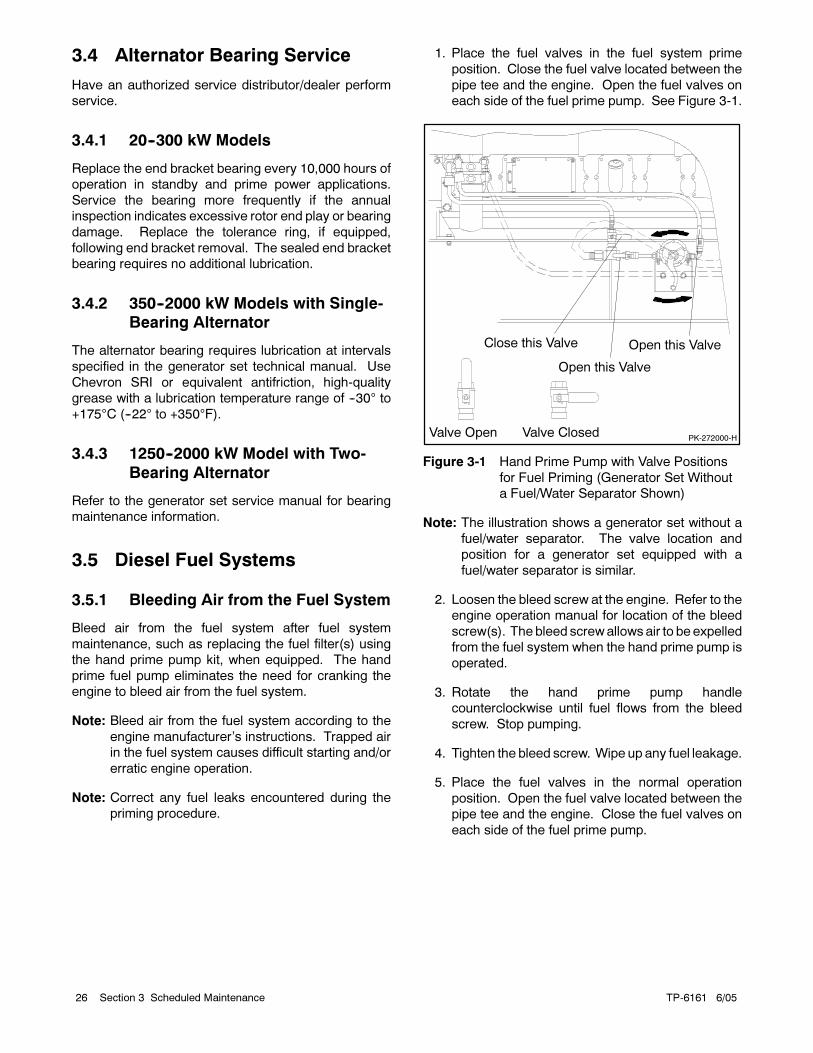
TP-6161 6/0526 Section 3 Scheduled Maintenance
3.4 Alternator Bearing Service
Have an authorized service distributor/dealer perform
service.
3.4.1 20--300 kW Models
Replace the end bracket bearing every 10,000 hours of
operation in standby and prime power applications.
Service the bearing more frequently if the annual
inspection indicates excessive rotor end play or bearing
damage. Replace the tolerance ring, if equipped,
following end bracket removal. The sealed end bracket
bearing requires no additional lubrication.
3.4.2 350--2000 kW Models with Single-
Bearing Alternator
The alternator bearing requires lubrication at intervals
specified in the generator set technical manual. Use
Chevron SRI or equivalent antifriction, high-quality
grease with a lubrication temperature range of --30° to
+175°C (--22° to +350°F).
3.4.3 1250--2000 kW Model with Two-
Bearing Alternator
Refer to the generator set service manual for bearing
maintenance information.
3.5 Diesel Fuel Systems
3.5.1 Bleeding Air from the Fuel System
Bleed air from the fuel system after fuel system
maintenance, such as replacing the fuel filter(s) using
the hand prime pump kit, when equipped. The hand
prime fuel pump eliminates the need for cranking the
engine to bleed air from the fuel system.
Note: Bleed air from the fuel system according to the
engine manufacturer’s instructions. Trapped air
in the fuel system causes difficult starting and/or
erratic engine operation.
Note: Correct any fuel leaks encountered during the
priming procedure.
1. Place the fuel valves in the fuel system prime
position. Close the fuel valve located between the
pipe tee and the engine. Open the fuel valves on
each side of the fuel prime pump. See Figure 3-1.
PK-272000-HValve Open Valve Closed
Close this Valve Open this Valve
Open this Valve
Figure 3-1 Hand Prime Pump with Valve Positions
for Fuel Priming (Generator Set Without
a Fuel/Water Separator Shown)
Note: The illustration shows a generator set without a
fuel/water separator. The valve location and
position for a generator set equipped with a
fuel/water separator is similar.
2. Loosen the bleed screw at the engine. Refer to the
engine operation manual for location of the bleed
screw(s). The bleed screwallows air to be expelled
from the fuel system when the hand prime pump is
operated.
3. Rotate the hand prime pump handle
counterclockwise until fuel flows from the bleed
screw. Stop pumping.
4. Tighten the bleed screw. Wipe up any fuel leakage.
5. Place the fuel valves in the normal operation
position. Open the fuel valve located between the
pipe tee and the engine. Close the fuel valves on
each side of the fuel prime pump.
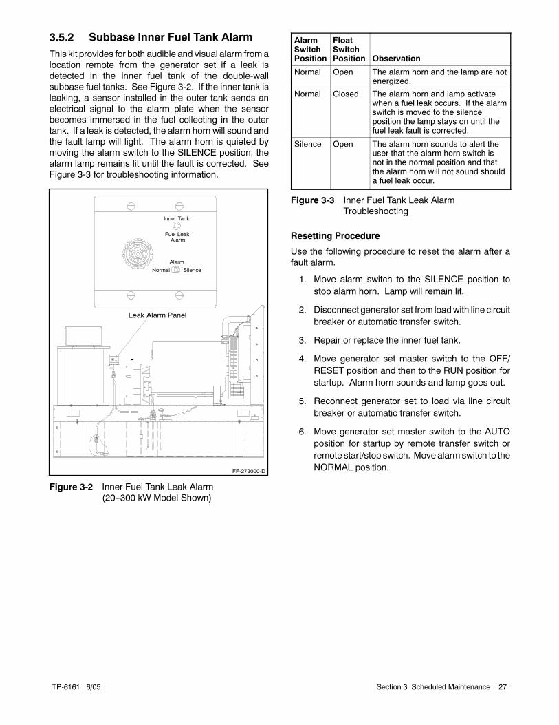
TP-6161 6/05 27Section 3 Scheduled Maintenance
3.5.2 Subbase Inner Fuel Tank Alarm
This kit provides for both audible and visual alarm froma
location remote from the generator set if a leak is
detected in the inner fuel tank of the double-wall
subbase fuel tanks. See Figure 3-2. If the inner tank is
leaking, a sensor installed in the outer tank sends an
electrical signal to the alarm plate when the sensor
becomes immersed in the fuel collecting in the outer
tank. If a leak is detected, the alarm horn will sound and
the fault lamp will light. The alarm horn is quieted by
moving the alarm switch to the SILENCE position; the
alarm lamp remains lit until the fault is corrected. See
Figure 3-3 for troubleshooting information.
Alarm
Normal Silence
Inner Tank
Fuel LeakAlarm
Leak Alarm Panel
FF-273000-D
Figure 3-2 Inner Fuel Tank Leak Alarm
(20--300 kW Model Shown)
AlarmSwitchPosition
FloatSwitchPosition Observation
Normal Open The alarm horn and the lamp are notenergized.
Normal Closed The alarm horn and lamp activatewhen a fuel leak occurs. If the alarmswitch is moved to the silenceposition the lamp stays on until thefuel leak fault is corrected.
Silence Open The alarm horn sounds to alert theuser that the alarm horn switch isnot in the normal position and thatthe alarm horn will not sound shoulda fuel leak occur.
Figure 3-3 Inner Fuel Tank Leak Alarm
Troubleshooting
Resetting Procedure
Use the following procedure to reset the alarm after a
fault alarm.
1. Move alarm switch to the SILENCE position to
stop alarm horn. Lamp will remain lit.
2. Disconnect generator set from loadwith line circuit
breaker or automatic transfer switch.
3. Repair or replace the inner fuel tank.
4. Move generator set master switch to the OFF/
RESET position and then to the RUN position for
startup. Alarm horn sounds and lamp goes out.
5. Reconnect generator set to load via line circuit
breaker or automatic transfer switch.
6. Move generator set master switch to the AUTO
position for startup by remote transfer switch or
remote start/stop switch. Move alarmswitch to the
NORMAL position.
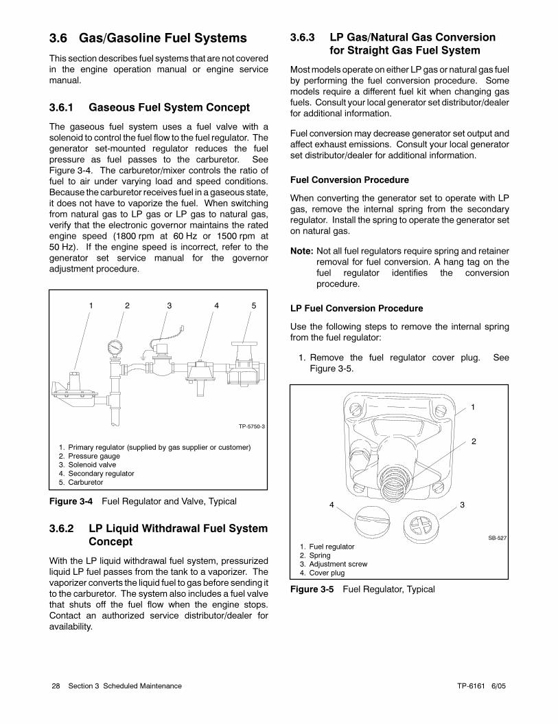
TP-6161 6/0528 Section 3 Scheduled Maintenance
3.6 Gas/Gasoline Fuel Systems
This section describes fuel systems that are not covered
in the engine operation manual or engine service
manual.
3.6.1 Gaseous Fuel System Concept
The gaseous fuel system uses a fuel valve with a
solenoid to control the fuel flow to the fuel regulator. The
generator set-mounted regulator reduces the fuel
pressure as fuel passes to the carburetor. See
Figure 3-4. The carburetor/mixer controls the ratio of
fuel to air under varying load and speed conditions.
Because the carburetor receives fuel in a gaseous state,
it does not have to vaporize the fuel. When switching
from natural gas to LP gas or LP gas to natural gas,
verify that the electronic governor maintains the rated
engine speed (1800 rpm at 60 Hz or 1500 rpm at
50 Hz). If the engine speed is incorrect, refer to the
generator set service manual for the governor
adjustment procedure.
1 2 3 4 5
TP-5750-3
1. Primary regulator (supplied by gas supplier or customer)
2. Pressure gauge3. Solenoid valve
4. Secondary regulator
5. Carburetor
Figure 3-4 Fuel Regulator and Valve, Typical
3.6.2 LP Liquid Withdrawal Fuel System
Concept
With the LP liquid withdrawal fuel system, pressurized
liquid LP fuel passes from the tank to a vaporizer. The
vaporizer converts the liquid fuel to gas before sending it
to the carburetor. The system also includes a fuel valve
that shuts off the fuel flow when the engine stops.
Contact an authorized service distributor/dealer for
availability.
3.6.3 LP Gas/Natural Gas Conversion
for Straight Gas Fuel System
Mostmodels operate on either LPgas or natural gas fuel
by performing the fuel conversion procedure. Some
models require a different fuel kit when changing gas
fuels. Consult your local generator set distributor/dealer
for additional information.
Fuel conversion may decrease generator set output and
affect exhaust emissions. Consult your local generator
set distributor/dealer for additional information.
Fuel Conversion Procedure
When converting the generator set to operate with LP
gas, remove the internal spring from the secondary
regulator. Install the spring to operate the generator set
on natural gas.
Note: Not all fuel regulators require spring and retainer
removal for fuel conversion. A hang tag on the
fuel regulator identifies the conversion
procedure.
LP Fuel Conversion Procedure
Use the following steps to remove the internal spring
from the fuel regulator:
1. Remove the fuel regulator cover plug. See
Figure 3-5.
SB-527
1. Fuel regulator
2. Spring3. Adjustment screw
4. Cover plug
1
2
34
Figure 3-5 Fuel Regulator, Typical
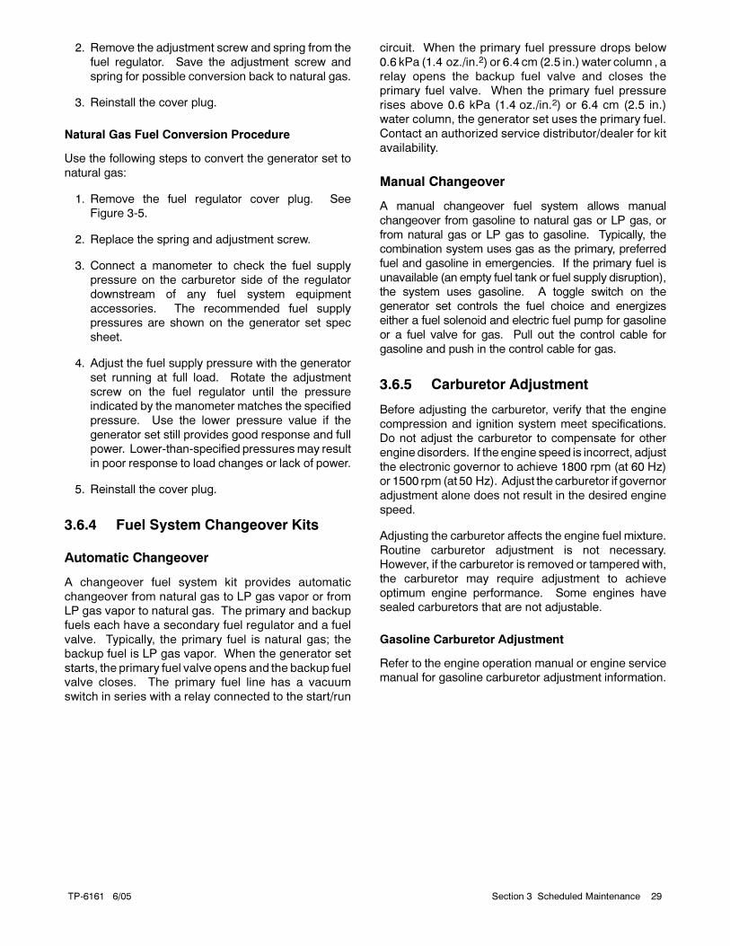
TP-6161 6/05 29Section 3 Scheduled Maintenance
2. Remove the adjustment screw and spring from the
fuel regulator. Save the adjustment screw and
spring for possible conversion back to natural gas.
3. Reinstall the cover plug.
Natural Gas Fuel Conversion Procedure
Use the following steps to convert the generator set to
natural gas:
1. Remove the fuel regulator cover plug. See
Figure 3-5.
2. Replace the spring and adjustment screw.
3. Connect a manometer to check the fuel supply
pressure on the carburetor side of the regulator
downstream of any fuel system equipment
accessories. The recommended fuel supply
pressures are shown on the generator set spec
sheet.
4. Adjust the fuel supply pressure with the generator
set running at full load. Rotate the adjustment
screw on the fuel regulator until the pressure
indicated by the manometer matches the specified
pressure. Use the lower pressure value if the
generator set still provides good response and full
power. Lower-than-specified pressuresmay result
in poor response to load changes or lack of power.
5. Reinstall the cover plug.
3.6.4 Fuel System Changeover Kits
Automatic Changeover
A changeover fuel system kit provides automatic
changeover from natural gas to LP gas vapor or from
LP gas vapor to natural gas. The primary and backup
fuels each have a secondary fuel regulator and a fuel
valve. Typically, the primary fuel is natural gas; the
backup fuel is LP gas vapor. When the generator set
starts, the primary fuel valve opens and the backup fuel
valve closes. The primary fuel line has a vacuum
switch in series with a relay connected to the start/run
circuit. When the primary fuel pressure drops below
0.6 kPa (1.4 oz./in.2) or 6.4 cm (2.5 in.) water column , a
relay opens the backup fuel valve and closes the
primary fuel valve. When the primary fuel pressure
rises above 0.6 kPa (1.4 oz./in.2) or 6.4 cm (2.5 in.)
water column, the generator set uses the primary fuel.
Contact an authorized service distributor/dealer for kit
availability.
Manual Changeover
A manual changeover fuel system allows manual
changeover from gasoline to natural gas or LP gas, or
from natural gas or LP gas to gasoline. Typically, the
combination system uses gas as the primary, preferred
fuel and gasoline in emergencies. If the primary fuel is
unavailable (an empty fuel tank or fuel supply disruption),
the system uses gasoline. A toggle switch on the
generator set controls the fuel choice and energizes
either a fuel solenoid and electric fuel pump for gasoline
or a fuel valve for gas. Pull out the control cable for
gasoline and push in the control cable for gas.
3.6.5 Carburetor Adjustment
Before adjusting the carburetor, verify that the engine
compression and ignition system meet specifications.
Do not adjust the carburetor to compensate for other
engine disorders. If the engine speed is incorrect, adjust
the electronic governor to achieve 1800 rpm (at 60 Hz)
or 1500 rpm (at 50 Hz). Adjust the carburetor if governor
adjustment alone does not result in the desired engine
speed.
Adjusting the carburetor affects the engine fuel mixture.
Routine carburetor adjustment is not necessary.
However, if the carburetor is removed or tampered with,
the carburetor may require adjustment to achieve
optimum engine performance. Some engines have
sealed carburetors that are not adjustable.
Gasoline Carburetor Adjustment
Refer to the engine operation manual or engine service
manual for gasoline carburetor adjustment information.
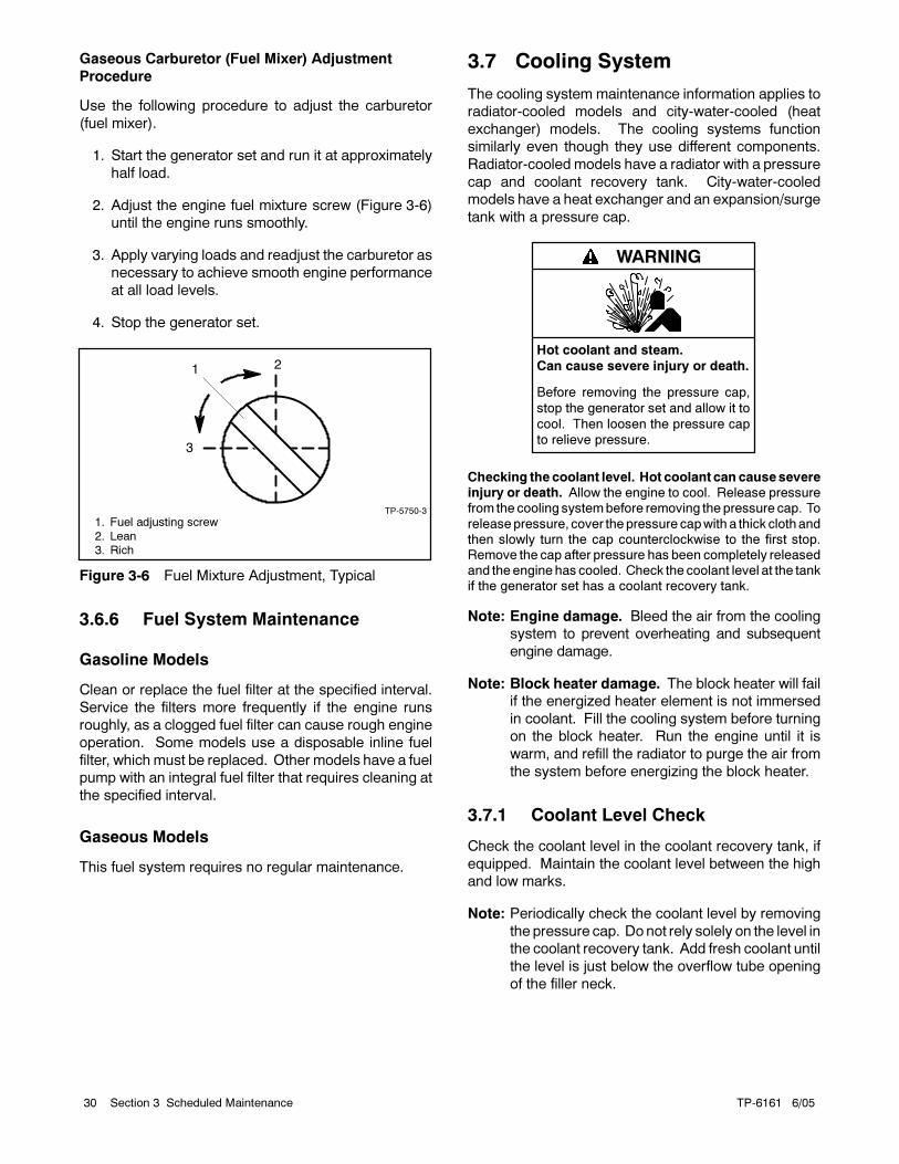
TP-6161 6/0530 Section 3 Scheduled Maintenance
Gaseous Carburetor (Fuel Mixer) Adjustment
Procedure
Use the following procedure to adjust the carburetor
(fuel mixer).
1. Start the generator set and run it at approximately
half load.
2. Adjust the engine fuel mixture screw (Figure 3-6)
until the engine runs smoothly.
3. Apply varying loads and readjust the carburetor as
necessary to achieve smooth engine performance
at all load levels.
4. Stop the generator set.
1 2
3
TP-5750-3
1. Fuel adjusting screw
2. Lean3. Rich
Figure 3-6 Fuel Mixture Adjustment, Typical
3.6.6 Fuel System Maintenance
Gasoline Models
Clean or replace the fuel filter at the specified interval.
Service the filters more frequently if the engine runs
roughly, as a clogged fuel filter can cause rough engine
operation. Some models use a disposable inline fuel
filter, which must be replaced. Other models have a fuel
pump with an integral fuel filter that requires cleaning at
the specified interval.
Gaseous Models
This fuel system requires no regular maintenance.
3.7 Cooling System
The cooling system maintenance information applies to
radiator-cooled models and city-water-cooled (heat
exchanger) models. The cooling systems function
similarly even though they use different components.
Radiator-cooled models have a radiator with a pressure
cap and coolant recovery tank. City-water-cooled
models have a heat exchanger and an expansion/surge
tank with a pressure cap.
Hot coolant and steam.
Can cause severe injury or death.
Before removing the pressure cap,
stop the generator set and allow it to
cool. Then loosen the pressure cap
to relieve pressure.
WARNING
Checking the coolant level. Hot coolant can causesevereinjury or death. Allow the engine to cool. Release pressurefrom the cooling systembefore removing thepressure cap. To
releasepressure, cover thepressure capwith a thick clothandthen slowly turn the cap counterclockwise to the first stop.Remove the cap after pressure has been completely releasedand theenginehas cooled. Check the coolant level at the tankif the generator set has a coolant recovery tank.
Note: Engine damage. Bleed the air from the cooling
system to prevent overheating and subsequent
engine damage.
Note: Block heater damage. The block heater will fail
if the energized heater element is not immersed
in coolant. Fill the cooling system before turning
on the block heater. Run the engine until it is
warm, and refill the radiator to purge the air from
the system before energizing the block heater.
3.7.1 Coolant Level Check
Check the coolant level in the coolant recovery tank, if
equipped. Maintain the coolant level between the high
and low marks.
Note: Periodically check the coolant level by removing
the pressure cap. Do not rely solely on the level in
the coolant recovery tank. Add fresh coolant until
the level is just below the overflow tube opening
of the filler neck.
TP-6161 6/05 31Section 3 Scheduled Maintenance
3.7.2 Cooling System Component
Inspection
To prevent generator set shutdown or damage caused
by overheating:
Keep the cooling air inlets clean and unobstructed.
Inspect the radiator’s exterior for obstructions.
Remove dirt and foreignmaterial using a soft brush or
cloth to avoid damaging the radiator fins.
Check the hoses and connections for leaks. Replace
any cracked, frayed, or spongy hoses.
Check the condition and tension of the radiator fan
and water pump belt(s). Follow the belt tension
procedure in this manual and/or the engine operation
manual.
Check the pressure cap seal and replacea crackedor
deteriorated cap. Remove dirt and other debris from
the pressure cap and filler neck. The pressure cap
raises the boiling point of the coolant, enabling higher
operating temperatures. Replace a leaking pressure
cap with one rated for the same pressure. The
pressure cap rating usually appears on the pressure
cap.
3.7.3 Cooling System Drainage
Procedure
For optimum protection, drain, flush, and refill the
cooling system at the intervals listed in the service
schedule.
Note: Dispose of all waste materials (oil, fuel, coolant,
filters, and gaskets) in an environmentally safe
manner.
1. Deenergize the block heater, if equipped.
2. Remove the pressure cap to allow the entire
system to drain and prevent air pockets from
restricting coolant flow through the engine block.
3. Open the radiator and/or engine block coolant
drain valve(s) and allow the system to drain.
4. If the inside of the radiator has mineral deposits or
the used coolant contains dirt or grease, refer to
Section 3.7.4, Cooling System Flush and Clean
Procedure. If the cooling system does not have
mineral deposits, go to Section 3.7.5, Cooling
System Refilling Procedure.
3.7.4 Cooling System Flush and Clean
Procedure
Use the instructions in the engine operation manual
when available to flush and clean the cooling system.
Otherwise, use the following procedure and the cooling
system cleaner manufacturer’s instructions.
1. Flush the cooling system with clean water.
2. If the inside of the radiator still has mineral
deposits, use a radiator cleaner to remove the
remaining deposits following the manufacturer’s
instructions.
3. Drain, clean, and flush the coolant recovery tank.
3.7.5 Cooling System Refilling
Procedure
See the generator set spec sheet for coolant capacity.
Note: Do not add coolant to a hot engine. Adding
coolant to a hot engine can cause the cylinder
block or cylinder head to crack. Wait until the
engine has cooled.
1. Remove the pressure cap.
2. Close radiator and/or engine block coolant drain
valve(s) and tighten cooling system hose clamps.
3. Open the air-bleed petcocks, if equipped. Close
the air-bleed petcocks when coolant begins to flow
from them.
4. Add coolant additives or water pump lubricants
according to the engine manufacturer’s
recommendations in the engine operation manual.
5. Fill the cooling system with the recommended
coolant/antifreeze mixture of 50% ethylene glycol
and 50% clean, softened water to inhibit
rust/corrosion and prevent freezing.
Note: A coolant solution of 50% ethylene glycol
provides freezing protection to --37°C
(--34°F) and overheating protection to
129°C (265°F). A coolant solution
containing less than 50% ethylene glycol
may not provide adequate freezing and
overheating protection. A coolant solution
containing more than 50% ethylene glycol
can cause engine or component damage.
Do not use alcohol or methanol antifreeze
or mix them with the specified coolant.
Refer to the engine operation manual for
recommendations regarding the coolant
mixture to use in extreme temperatures.
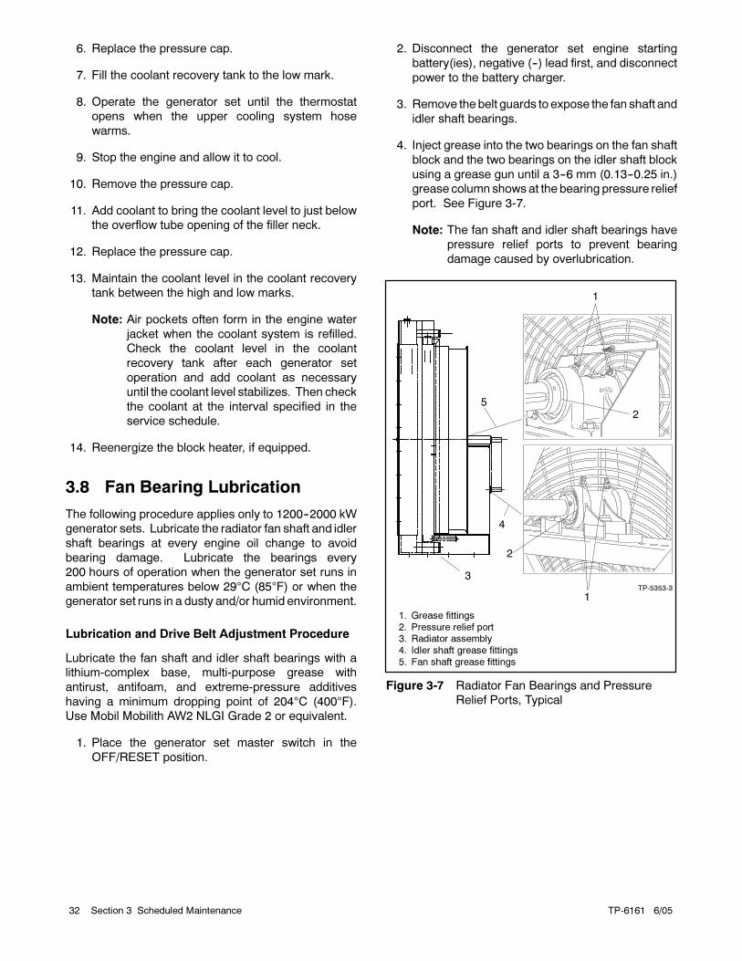
TP-6161 6/0532 Section 3 Scheduled Maintenance
6. Replace the pressure cap.
7. Fill the coolant recovery tank to the low mark.
8. Operate the generator set until the thermostat
opens when the upper cooling system hose
warms.
9. Stop the engine and allow it to cool.
10. Remove the pressure cap.
11. Add coolant to bring the coolant level to just below
the overflow tube opening of the filler neck.
12. Replace the pressure cap.
13. Maintain the coolant level in the coolant recovery
tank between the high and low marks.
Note: Air pockets often form in the engine water
jacket when the coolant system is refilled.
Check the coolant level in the coolant
recovery tank after each generator set
operation and add coolant as necessary
until the coolant level stabilizes. Then check
the coolant at the interval specified in the
service schedule.
14. Reenergize the block heater, if equipped.
3.8 Fan Bearing Lubrication
The following procedure applies only to 1200--2000 kW
generator sets. Lubricate the radiator fan shaft and idler
shaft bearings at every engine oil change to avoid
bearing damage. Lubricate the bearings every
200 hours of operation when the generator set runs in
ambient temperatures below 29°C (85°F) or when the
generator set runs in a dusty and/or humid environment.
Lubrication and Drive Belt Adjustment Procedure
Lubricate the fan shaft and idler shaft bearings with a
lithium-complex base, multi-purpose grease with
antirust, antifoam, and extreme-pressure additives
having a minimum dropping point of 204°C (400°F).
Use Mobil Mobilith AW2 NLGI Grade 2 or equivalent.
1. Place the generator set master switch in the
OFF/RESET position.
2. Disconnect the generator set engine starting
battery(ies), negative (--) lead first, and disconnect
power to the battery charger.
3. Remove the belt guards to expose the fan shaft and
idler shaft bearings.
4. Inject grease into the two bearings on the fan shaft
block and the two bearings on the idler shaft block
using a grease gun until a 3--6 mm (0.13--0.25 in.)
grease column showsat the bearing pressure relief
port. See Figure 3-7.
Note: The fan shaft and idler shaft bearings have
pressure relief ports to prevent bearing
damage caused by overlubrication.
1
2
TP-5353-3
3
1
25
4
1. Grease fittings
2. Pressure relief port3. Radiator assembly
4. Idler shaft grease fittings
5. Fan shaft grease fittings
Figure 3-7 Radiator Fan Bearings and Pressure
Relief Ports, Typical
TP-6161 6/05 33Section 3 Scheduled Maintenance
5. Remove excess grease from the bearing pressure
relief ports.
6. Inspect the fan drive belt and replace if it is damaged
or worn. Check the fan belt tension using a poly
V-belt tension gauge and adjust the tension, if
necessary. See Figure 3-8.
Generator Set
Model
New Belt,
N (lbf.)
Used Belt,*
N (lbf.)
1200-2000 kW2450--2890(550--650)
1650--1910(370--430)
* A belt is considered used after 50 hours of service.
Figure 3-8 Poly V-Belt Tension Specifications
7. Reinstall the belt guards using the original
hardware.
8. Reconnect the generator set engine starting
battery(ies), negative (--) lead last.
9. Test run the generator set for a few minutes and
listen for belt noise (squeal) indicating a slipping
belt. Stop the generator set.
If the belt slips after the belt tension procedure, clean the
pulley surfaces and repeat the belt tension procedure. If
slippage continues, replace the fan belt.
3.9 Battery
Sulfuric acid in batteries.Can cause severe injury or death.
Wear protective goggles andclothing. Battery acid may cause
blindness and burn skin.
WARNING
Battery gases. Explosion can cause severe injury ordeath. Battery gases can cause an explosion. Do not smokeor permit flames or sparks to occur near a battery at any time,particularlywhen it is charging. Donot disposeof abattery ina
fire. To prevent burns and sparks that could cause anexplosion, avoid touching the battery terminals with tools orother metal objects. Remove all jewelry before servicing theequipment. Discharge static electricity from your body beforetouching batteries by first touching a grounded metal surfaceaway from the battery. To avoid sparks, do not disturb the
battery charger connections while the battery is charging.Always turn the battery charger off before disconnecting thebattery connections. Ventilate the compartments containingbatteries to prevent accumulation of explosive gases.
Battery short circuits. Explosion can cause severe injuryor death. Short circuits can cause bodily injury and/or
equipment damage. Disconnect the battery before generatorset installation or maintenance. Remove all jewelry beforeservicing the equipment. Use tools with insulated handles.Remove the negative (--) lead first when disconnecting thebattery. Reconnect the negative (--) lead last whenreconnecting the battery. Never connect the negative (--)
battery cable to the positive (+) connection terminal of thestarter solenoid. Do not test the battery condition by shortingthe terminals together.
Battery electrolyte is a diluted sulfuric acid. Battery acidcan cause severe injury or death. Battery acid can causeblindness and burn skin. Always wear splashproof safety
goggles, rubber gloves, and boots when servicing the battery.Do not open a sealed battery or mutilate the battery case. Ifbattery acid splashes in the eyes or on the skin, immediatelyflush the affected area for 15 minutes with large quantities ofclean water. Seek immediate medical aid in the case of eye
contact. Never addacid to a battery after placing the battery inservice, as this may result in hazardous spattering of batteryacid.
Battery acid cleanup. Battery acid can cause severeinjury or death. Battery acid is electrically conductive andcorrosive. Add 500 g (1 lb.) of bicarbonate of soda (baking
soda) to a container with 4 L (1 gal.) of water and mix theneutralizing solution. Pour the neutralizing solution on thespilled battery acid and continue to add the neutralizingsolution to the spilled battery acid until all evidence of achemical reaction (foaming) has ceased. Flush the resultingliquid with water and dry the area.
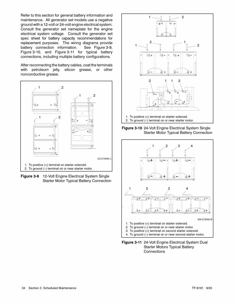
TP-6161 6/0534 Section 3 Scheduled Maintenance
Refer to this section for general battery information and
maintenance. All generator set models use a negative
groundwith a 12-volt or 24-volt engine electrical system.
Consult the generator set nameplate for the engine
electrical system voltage. Consult the generator set
spec sheet for battery capacity recommendations for
replacement purposes. The wiring diagrams provide
battery connection information. See Figure 3-9,
Figure 3-10, and Figure 3-11 for typical battery
connections, including multiple battery configurations.
After reconnecting the battery cables, coat the terminals
with petroleum jelly, silicon grease, or other
nonconductive grease.
EZ-273000-J
1 2
1 2
1 2
1. To positive (+) terminal on starter solenoid.
2. To ground (--) terminal on or near starter motor.
Figure 3-9 12-Volt Engine Electrical System Single
Starter Motor Typical Battery Connection
1
11
1 1
2
2
2
2
2
1. To positive (+) terminal on starter solenoid.
2. To ground (--) terminal on or near starter motor.
Figure 3-10 24-Volt Engine Electrical System Single
Starter Motor Typical Battery Connection
4321
1 2 3 4
KW-272000-B
1. To positive (+) terminal on starter solenoid.
2. To ground (--) terminal on or near starter motor.3. To positive (+) terminal on second starter solenoid.
4. To ground (--) terminal on or near second starter motor.
Figure 3-11 24-Volt Engine Electrical System Dual
Starter Motors Typical Battery
Connections
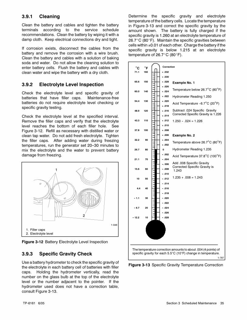
TP-6161 6/05 35Section 3 Scheduled Maintenance
3.9.1 Cleaning
Clean the battery and cables and tighten the battery
terminals according to the service schedule
recommendations. Clean the battery by wiping it with a
damp cloth. Keep electrical connections dry and tight.
If corrosion exists, disconnect the cables from the
battery and remove the corrosion with a wire brush.
Clean the battery and cables with a solution of baking
soda and water. Do not allow the cleaning solution to
enter battery cells. Flush the battery and cables with
clean water and wipe the battery with a dry cloth.
3.9.2 Electrolyte Level Inspection
Check the electrolyte level and specific gravity of
batteries that have filler caps. Maintenance-free
batteries do not require electrolyte level checking or
specific gravity testing.
Check the electrolyte level at the specified interval.
Remove the filler caps and verify that the electrolyte
level reaches the bottom of each filler hole. See
Figure 3-12. Refill as necessary with distilled water or
clean tap water. Do not add fresh electrolyte. Tighten
the filler caps. After adding water during freezing
temperatures, run the generator set 20--30 minutes to
mix the electrolyte and the water to prevent battery
damage from freezing.
1-046
1
2
1. Filler caps
2. Electrolyte level
Figure 3-12 Battery Electrolyte Level Inspection
3.9.3 Specific Gravity Check
Use a battery hydrometer to check the specific gravity of
the electrolyte in each battery cell of batteries with filler
caps. Holding the hydrometer vertically, read the
number on the glass bulb at the top of the electrolyte
level or the number adjacent to the pointer. If the
hydrometer used does not have a correction table,
consult Figure 3-13.
Determine the specific gravity and electrolyte
temperature of the battery cells. Locate the temperature
in Figure 3-13 and correct the specific gravity by the
amount shown. The battery is fully charged if the
specific gravity is 1.260 at an electrolyte temperature of
26.7C (80F). Maintain the specific gravities between
cells within ±0.01 of each other. Charge the battery if the
specific gravity is below 1.215 at an electrolyte
temperature of 26.7C (80F).
10
20
30
40
50
60
70
80
90
100
110
120
130
140
150
160
-- 12.2
-- 6.7
-- 1.1
4.4
10
21.1
26.7
32.2
37.8
43.3
48.9
54.4
60.0
65.6
71.1
15.6
+ .032
+ .030
+ .028
+ .026
+ .024
+ .022
+ .020
+ .018
+ .016
+ .014
+ .012
+ .010
+ .008
+ .006
+ .004
+ .002
0
-- .002
-- .004
--. 006
-- .008
-- .010
-- .012
-- .014
-- .016
-- .018
-- .020
-- .022
-- .024
-- .026
-- .028
°C °F
Example No. 1
Temperature below 26.7°C (80°F)
Hydrometer Reading 1.250
Acid Temperature --6.7°C (20°F)
Subtract .024 Specific GravityCorrected Specific Gravity is 1.226
1.250 -- .024 = 1.226
Example No. 2
Temperature above 26.7°C (80°F)
Hydrometer Reading 1.235
Acid Temperature 37.8°C (100°F)
Add .008 Specific GravityCorrected Specific Gravity is1.243
1.235 + .008 = 1.243
The temperature correction amounts to about .004 (4 points) ofspecific gravity for each 5.5°C (10°F) change in temperature.
Correction
1-787
Figure 3-13 Specific Gravity Temperature Correction
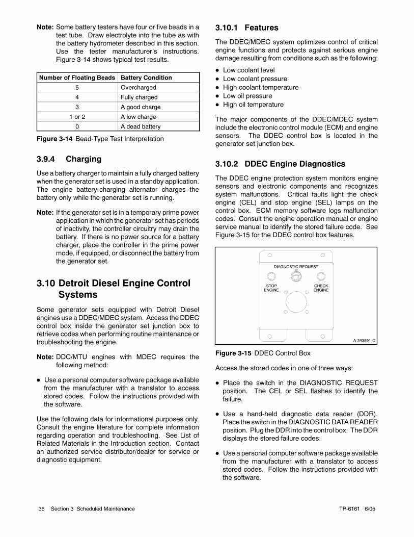
TP-6161 6/0536 Section 3 Scheduled Maintenance
Note: Some battery testers have four or five beads in a
test tube. Draw electrolyte into the tube as with
the battery hydrometer described in this section.
Use the tester manufacturer’s instructions.
Figure 3-14 shows typical test results.
Number of Floating Beads Battery Condition
5 Overcharged
4 Fully charged
3 A good charge
1 or 2 A low charge
0 A dead battery
Figure 3-14 Bead-Type Test Interpretation
3.9.4 Charging
Use a battery charger tomaintain a fully charged battery
when the generator set is used in a standby application.
The engine battery-charging alternator charges the
battery only while the generator set is running.
Note: If the generator set is in a temporary prime power
application in which the generator set has periods
of inactivity, the controller circuitry may drain the
battery. If there is no power source for a battery
charger, place the controller in the prime power
mode, if equipped, or disconnect the battery from
the generator set.
3.10 Detroit Diesel Engine Control
Systems
Some generator sets equipped with Detroit Diesel
engines use aDDEC/MDECsystem. Access theDDEC
control box inside the generator set junction box to
retrieve codes when performing routine maintenance or
troubleshooting the engine.
Note: DDC/MTU engines with MDEC requires the
following method:
Use a personal computer software package available
from the manufacturer with a translator to access
stored codes. Follow the instructions provided with
the software.
Use the following data for informational purposes only.
Consult the engine literature for complete information
regarding operation and troubleshooting. See List of
Related Materials in the Introduction section. Contact
an authorized service distributor/dealer for service or
diagnostic equipment.
3.10.1 Features
The DDEC/MDEC system optimizes control of critical
engine functions and protects against serious engine
damage resulting from conditions such as the following:
Low coolant level
Low coolant pressure
High coolant temperature
Low oil pressure
High oil temperature
The major components of the DDEC/MDEC system
include the electronic control module (ECM) and engine
sensors. The DDEC control box is located in the
generator set junction box.
3.10.2 DDEC Engine Diagnostics
The DDEC engine protection system monitors engine
sensors and electronic components and recognizes
system malfunctions. Critical faults light the check
engine (CEL) and stop engine (SEL) lamps on the
control box. ECM memory software logs malfunction
codes. Consult the engine operation manual or engine
service manual to identify the stored failure code. See
Figure 3-15 for the DDEC control box features.
A-343591-C
Figure 3-15 DDEC Control Box
Access the stored codes in one of three ways:
Place the switch in the DIAGNOSTIC REQUEST
position. The CEL or SEL flashes to identify the
failure.
Use a hand-held diagnostic data reader (DDR).
Place the switch in theDIAGNOSTICDATAREADER
position. Plug theDDR into the control box. TheDDR
displays the stored failure codes.
Use a personal computer software package available
from the manufacturer with a translator to access
stored codes. Follow the instructions provided with
the software.
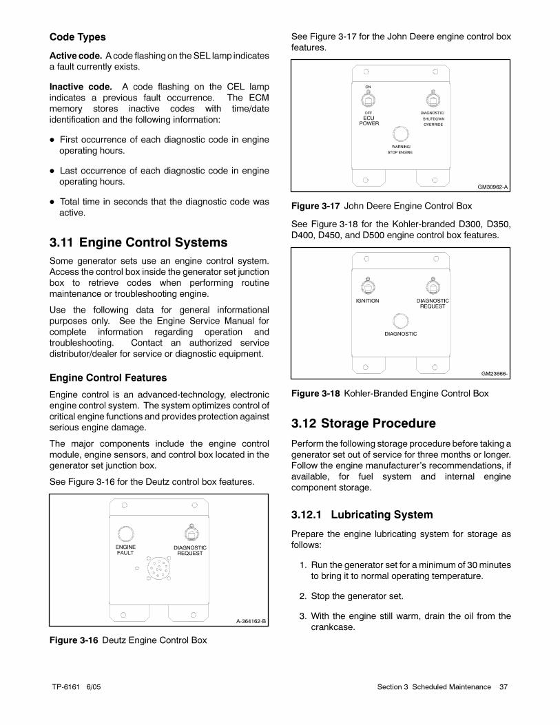
TP-6161 6/05 37Section 3 Scheduled Maintenance
Code Types
Active code. Acode flashing on theSEL lamp indicates
a fault currently exists.
Inactive code. A code flashing on the CEL lamp
indicates a previous fault occurrence. The ECM
memory stores inactive codes with time/date
identification and the following information:
First occurrence of each diagnostic code in engine
operating hours.
Last occurrence of each diagnostic code in engine
operating hours.
Total time in seconds that the diagnostic code was
active.
3.11 Engine Control Systems
Some generator sets use an engine control system.
Access the control box inside the generator set junction
box to retrieve codes when performing routine
maintenance or troubleshooting engine.
Use the following data for general informational
purposes only. See the Engine Service Manual for
complete information regarding operation and
troubleshooting. Contact an authorized service
distributor/dealer for service or diagnostic equipment.
Engine Control Features
Engine control is an advanced-technology, electronic
engine control system. The system optimizes control of
critical engine functions and provides protection against
serious engine damage.
The major components include the engine control
module, engine sensors, and control box located in the
generator set junction box.
See Figure 3-16 for the Deutz control box features.
A-364162-B
Figure 3-16 Deutz Engine Control Box
See Figure 3-17 for the John Deere engine control box
features.
GM30962-A
Figure 3-17 John Deere Engine Control Box
See Figure 3-18 for the Kohler-branded D300, D350,
D400, D450, and D500 engine control box features.
GM23666-
Figure 3-18 Kohler-Branded Engine Control Box
3.12 Storage Procedure
Perform the following storage procedure before taking a
generator set out of service for three months or longer.
Follow the engine manufacturer’s recommendations, if
available, for fuel system and internal engine
component storage.
3.12.1 Lubricating System
Prepare the engine lubricating system for storage as
follows:
1. Run the generator set for a minimum of 30 minutes
to bring it to normal operating temperature.
2. Stop the generator set.
3. With the engine still warm, drain the oil from the
crankcase.
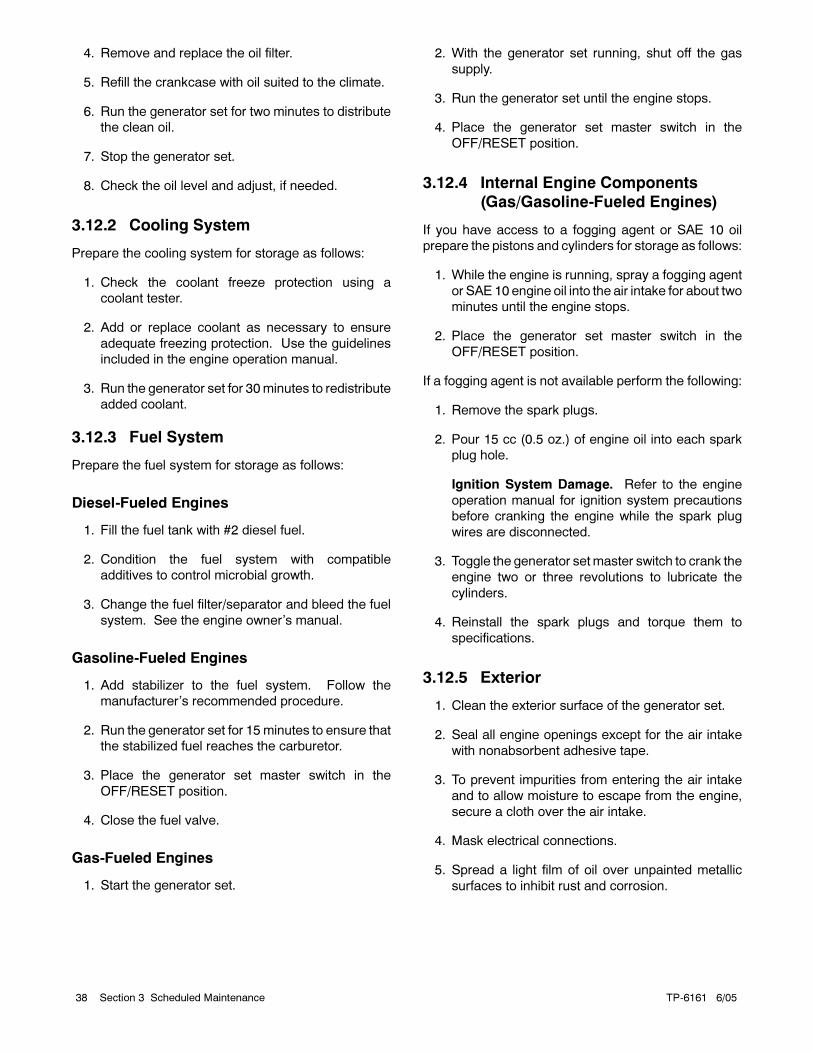
TP-6161 6/0538 Section 3 Scheduled Maintenance
4. Remove and replace the oil filter.
5. Refill the crankcase with oil suited to the climate.
6. Run the generator set for two minutes to distribute
the clean oil.
7. Stop the generator set.
8. Check the oil level and adjust, if needed.
3.12.2 Cooling System
Prepare the cooling system for storage as follows:
1. Check the coolant freeze protection using a
coolant tester.
2. Add or replace coolant as necessary to ensure
adequate freezing protection. Use the guidelines
included in the engine operation manual.
3. Run the generator set for 30minutes to redistribute
added coolant.
3.12.3 Fuel System
Prepare the fuel system for storage as follows:
Diesel-Fueled Engines
1. Fill the fuel tank with #2 diesel fuel.
2. Condition the fuel system with compatible
additives to control microbial growth.
3. Change the fuel filter/separator and bleed the fuel
system. See the engine owner’s manual.
Gasoline-Fueled Engines
1. Add stabilizer to the fuel system. Follow the
manufacturer’s recommended procedure.
2. Run the generator set for 15 minutes to ensure that
the stabilized fuel reaches the carburetor.
3. Place the generator set master switch in the
OFF/RESET position.
4. Close the fuel valve.
Gas-Fueled Engines
1. Start the generator set.
2. With the generator set running, shut off the gas
supply.
3. Run the generator set until the engine stops.
4. Place the generator set master switch in the
OFF/RESET position.
3.12.4 Internal Engine Components
(Gas/Gasoline-Fueled Engines)
If you have access to a fogging agent or SAE 10 oil
prepare the pistons and cylinders for storage as follows:
1. While the engine is running, spray a fogging agent
or SAE 10 engine oil into the air intake for about two
minutes until the engine stops.
2. Place the generator set master switch in the
OFF/RESET position.
If a fogging agent is not available perform the following:
1. Remove the spark plugs.
2. Pour 15 cc (0.5 oz.) of engine oil into each spark
plug hole.
Ignition System Damage. Refer to the engine
operation manual for ignition system precautions
before cranking the engine while the spark plug
wires are disconnected.
3. Toggle the generator setmaster switch to crank the
engine two or three revolutions to lubricate the
cylinders.
4. Reinstall the spark plugs and torque them to
specifications.
3.12.5 Exterior
1. Clean the exterior surface of the generator set.
2. Seal all engine openings except for the air intake
with nonabsorbent adhesive tape.
3. To prevent impurities from entering the air intake
and to allow moisture to escape from the engine,
secure a cloth over the air intake.
4. Mask electrical connections.
5. Spread a light film of oil over unpainted metallic
surfaces to inhibit rust and corrosion.
TP-6161 6/05 39Section 3 Scheduled Maintenance
3.12.6 Battery
Perform battery storage after all other storage
procedures.
1. Place the generator set master switch in the
OFF/RESET position.
2. Disconnect the battery(ies), negative (--) lead first.
3. Clean the battery. Refer to Section 3.9.1 for the
battery cleaning procedure.
4. Place the battery in a cool, dry location.
5. Connect the battery to a float/equalize battery
charger or charge it monthly with a trickle battery
charger. Refer to the battery charger
manufacturer’s recommendations.
Maintain a full charge to extend battery life.

TP-6161 6/0540 Section 3 Scheduled Maintenance
Notes
TP-6161 6/05 41Section 4 Troubleshooting
Section 4 Troubleshooting
This section contains generator set troubleshooting,
diagnostic, and repair information.
Use the chart on the following page to diagnose and
correct common problems. First check for simple
causes such as a dead engine starting battery or an
open circuit breaker. The chart includes a list of
common problems, possible causes of the problem,
recommended corrective actions, and references to
detailed information or repair procedures.
Maintain a record of repairs and adjustments performed
on the equipment. If the procedures in this manual do
not explain how to correct the problem, contact an
authorized distributor/dealer. Use the record to help
describe the problem and repairs or adjustments made
to the equipment.
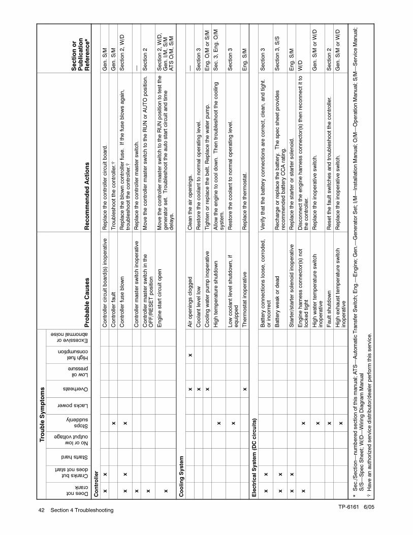
TP-6161 6/0542 Section 4 Troubleshooting
Trouble
Symptoms
Doesnotcrank
Cranksbutdoesnotstart
Startshard
Noorlowoutputvoltage
Stopssuddenly
Lackspower
Overheats
Lowoilpressure
Highfuelconsumption
Excessiveorabnormalnoise
Probable
Causes
RecommendedActions
Sectionor
Publication
Reference*
Controller
xx
Controllercircuitboard(s)inoperative
Replacethecontrollercircuitboard.
Gen.S/M
xControllerfault
Troubleshootthecontroller.
Gen.S/M
xx
xControlle
rfuseblown
Replacetheblowncontrolle
rfuse.Ifthefuseblowsagain,
troubleshootthecontroller.
Section2,W/D
xControlle
rmasterswitchinoperative
Replacethecontrolle
rmasterswitch.
—
xControlle
rmasterswitchin
the
OFF/RESETposition
Movethecontrolle
rmasterswitchto
theRUNorAUTO
position.
Section2
xEnginestartcircuitopen
Movethecontrolle
rmasterswitchto
theRUNpositionto
testthe
generatorset.
Troubleshoottheauto
startcircuitandtime
delays.
Section2,W/D,
Gen.I/M,S/M
ATSO/M
,S/M
CoolingSystem
xx
Airopeningsclogged
Cleantheairopenings.
—
xCoolantlevellow
Restore
thecoolantto
norm
aloperatinglevel.
Section3
xCoolin
gwaterpumpinoperative
Tightenorreplacethebelt.Replacethewaterpump.
Eng.O/M
orS/M
xHightemperature
shutdown
Allo
wtheengineto
cooldown.Thentroubleshootthecoolin
gsystem.
Sec.3,Eng.O/M
xLowcoolantlevelshutdown,if
equipped
Restore
thecoolantto
norm
aloperatinglevel.
Section3
xTherm
ostatinoperative
Replacethetherm
ostat.
Eng.S/M
ElectricalSystem
(DCcircuits)
xx
Battery
connectionsloose,corroded,
orincorrect
Verify
thatthebattery
connectionsare
correct,clean,andtight.
Section3
xx
Battery
weakordead
Rechargeorreplacethebattery.Thespecsheetprovides
recommendedbattery
CCArating.
Section3,S/S
xx
Starter/startersolenoid
inoperative
Replacethestarterorstartersolenoid.
Eng.S/M
xx
Engineharnessconnector(s)not
lockedtight
Disconnecttheengineharnessconnector(s)thenreconnectitto
thecontroller.
W/D
xHighwatertemperature
switch
inoperative
Replacetheinoperativeswitch.
Gen.S/M
orW/D
xFaultshutdown
Resetthefaultswitchesandtroubleshootthecontrolle
r.Section2
xHighexhausttemperature
switch
inoperative
Replacetheinoperativeswitch.
Gen.S/M
orW/D
*Sec./Section—numberedsectionofthismanual;ATS—AutomaticTransferSwitch;Eng.—
Engine;Gen.—
GeneratorSet;I/M—InstallationManual;O/M
—OperationManual;S/M
—ServiceManual;
S/S—SpecSheet;W/D—WiringDiagram
Manual
Haveanauthorizedservicedistributor/dealerperform
this
service.
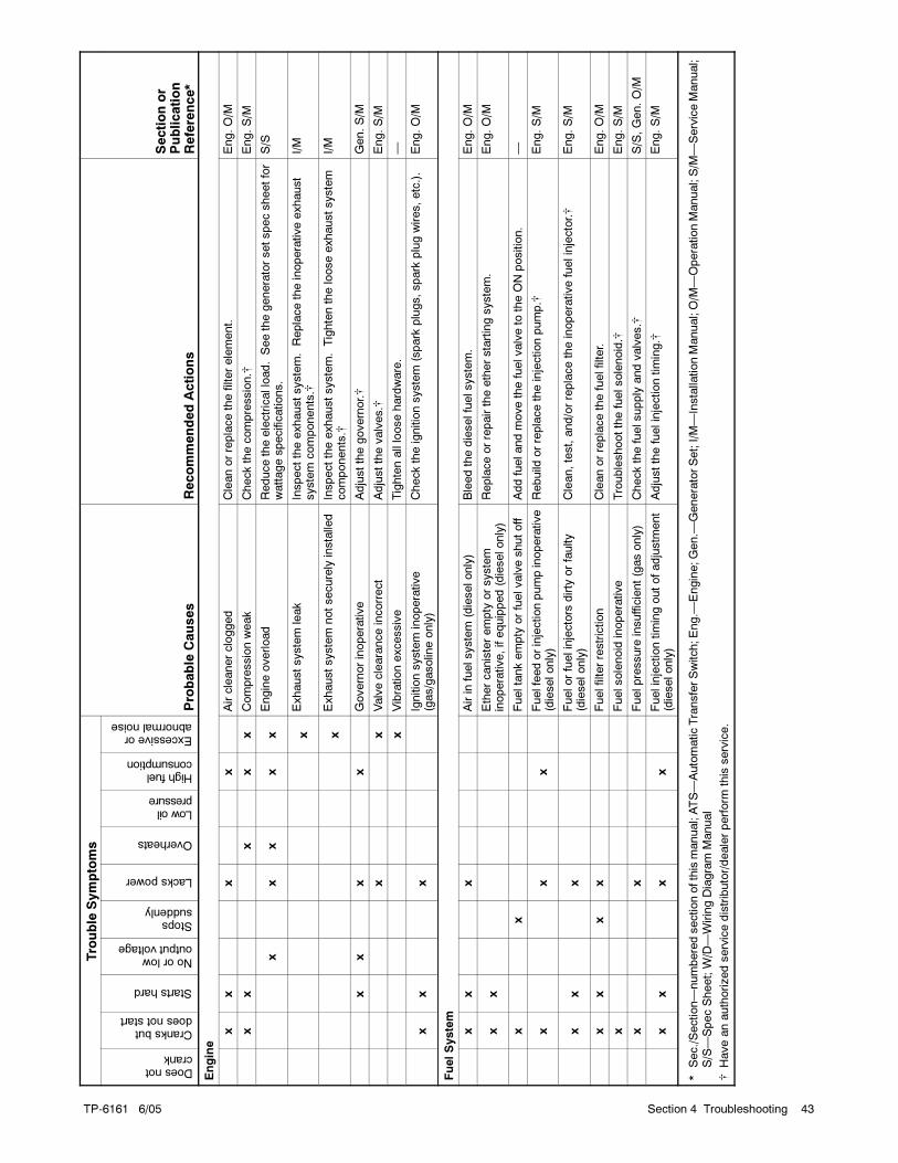
TP-6161
6/05
TP-6161 6/05 43Section 4 Troubleshooting
Sectionor
Publication
Reference*
RecommendedActions
Probable
Causes
Trouble
Symptoms
Sectionor
Publication
Reference*
RecommendedActions
Probable
Causes
Excessiveorabnormalnoise
Highfuelconsumption
Lowoilpressure
Overheats
Lackspower
Stopssuddenly
Noorlowoutputvoltage
Startshard
Cranksbutdoesnotstart
Doesnotcrank
Engine
xx
xx
Aircleanerclogged
Cleanorreplacethefilterelement.
Eng.O/M
xx
xx
xCompressionweak
Checkthecompression.
Eng.S/M
xx
xx
xEngineoverload
Reducetheelectricalload.Seethegeneratorsetspecsheetfor
wattagespecifications.
S/S
xExhaustsystem
leak
Inspecttheexhaustsystem.Replacetheinoperativeexhaust
system
components.
I/M
xExhaustsystem
notsecurely
installe
dInspecttheexhaustsystem.Tightenthelooseexhaustsystem
components.
I/M
xx
xx
Governorinoperative
Adjustthegovernor.
Gen.S/M
xx
Valveclearanceincorrect
Adjustthevalves.
Eng.S/M
xVibrationexcessive
Tightenallloosehardware.
—
xx
xIgnitionsystem
inoperative
(gas/gasolin
eonly)
Checktheignitionsystem
(spark
plugs,spark
plugwires,etc.).
Eng.O/M
FuelSystem
xx
xAirin
fuelsystem
(dieselonly)
Bleedthedieselfuelsystem.
Eng.O/M
xx
Ethercanisterempty
orsystem
inoperative,ifequipped(dieselonly)
Replaceorrepairtheetherstartingsystem.
Eng.O/M
xx
Fueltankempty
orfuelvalveshutoff
Addfuelandmovethefuelvalveto
theONposition.
—
xx
xFuelfeedorinjectionpumpinoperative
(dieselonly)
Rebuild
orreplacetheinjectionpump.
Eng.S/M
xx
xFuelorfuelinjectors
dirty
orfaulty
(dieselonly)
Clean,test,and/orreplacetheinoperativefuelinjector.
Eng.S/M
xx
xx
Fuelfilterrestriction
Cleanorreplacethefuelfilter.
Eng.O/M
xFuelsolenoid
inoperative
Troubleshootthefuelsolenoid.
Eng.S/M
xx
Fuelpressure
insufficient(gasonly)
Checkthefuelsupply
andvalves.
S/S,Gen.O/M
xx
xx
Fuelinjectiontimingoutofadjustm
ent
(dieselonly)
Adjustthefuelinjectiontiming.
Eng.S/M
*Sec./Section—numberedsectionofthismanual;ATS—AutomaticTransferSwitch;Eng.—
Engine;Gen.—
GeneratorSet;I/M—InstallationManual;O/M
—OperationManual;S/M
—ServiceManual;
S/S—SpecSheet;W/D—WiringDiagram
Manual
Haveanauthorizedservicedistributor/dealerperform
this
service.
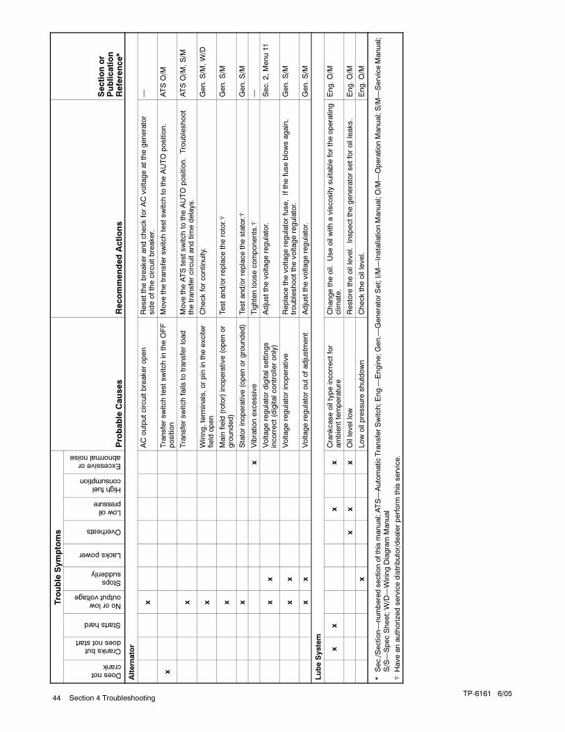
TP-6161 6/0544 Section 4 Troubleshooting
Sectionor
Publication
Reference*
RecommendedActions
Probable
Causes
Trouble
Symptoms
Sectionor
Publication
Reference*
RecommendedActions
Probable
Causes
Excessiveorabnormalnoise
Highfuelconsumption
Lowoilpressure
Overheats
Lackspower
Stopssuddenly
Noorlowoutputvoltage
Startshard
Cranksbutdoesnotstart
Doesnotcrank
Altern
ator
xACoutputcircuitbreakeropen
ResetthebreakerandcheckforACvoltageatthegenerator
sideofthecircuitbreaker.
—
xTransferswitchtestswitchin
theOFF
position
Movethetransferswitchtestswitchto
theAUTO
position.
ATSO/M
xTransferswitchfails
totransferload
MovetheATStestswitchto
theAUTO
position.Troubleshoot
thetransfercircuitandtimedelays.
ATSO/M
,S/M
xWiring,term
inals,orpin
intheexciter
field
open
Checkforcontinuity.
Gen.S/M
,W/D
xMain
field
(rotor)inoperative(openor
grounded)
Testand/orreplacetherotor.
Gen.S/M
xStatorinoperative(openorgrounded)
Testand/orreplacethestator.
Gen.S/M
xVibrationexcessive
Tightenloosecomponents.
—
xx
Voltageregulatordigitalsettings
incorrect(digitalcontrolleronly)
Adjustthevoltageregulator.
Sec.2,Menu11
xx
Voltageregulatorinoperative
Replacethevoltageregulatorfuse,Ifthefuseblowsagain,
troubleshootthevoltageregulator.
Gen.S/M
xx
Voltageregulatoroutofadjustm
ent
Adjustthevoltageregulator.
Gen.S/M
LubeSystem
xx
xx
Crankcaseoiltypeincorrectfor
ambienttemperature
Changetheoil.
Useoilwithaviscositysuitable
fortheoperating
clim
ate.
Eng.O/M
xx
xOillevellow
Restore
theoillevel.
Inspectthegeneratorsetforoilleaks.
Eng.O/M
xLowoilpressure
shutdown
Checktheoillevel.
Eng.O/M
*Sec./Section—numberedsectionofthismanual;ATS—AutomaticTransferSwitch;Eng.—
Engine;Gen.—
GeneratorSet;I/M—InstallationManual;O/M
—OperationManual;S/M
—ServiceManual;
S/S—SpecSheet;W/D—WiringDiagram
Manual
Haveanauthorizedservicedistributor/dealerperform
this
service.
TP-6161 6/05 45Section 5 Generator Set Reconnection
Section 5 Generator Set Reconnection
5.1 Voltage Reconnection
To change the voltage of 10- or 12-lead generator sets,
use the following voltage reconnection procedure.
Adjust the governor and voltage regulator for frequency
changes. Consult the generator set service manual for
frequency adjustment information.
Voltage reconnection. Affix a notice to the generator setafter reconnecting the set to a voltage different from thevoltage on the nameplate. Order voltage reconnectiondecal 246242 from an authorized service distributor/dealer.
Equipment damage. Verify that the voltage ratings of
the transfer switch, line circuit breakers, and other
accessories match the selected line voltage.
Accidental starting.Can cause severe injury or death.
Disconnect the battery cables beforeworking on the generator set.
Remove the negative (--) lead firstwhen disconnecting the battery.Reconnect the negative (--) lead lastwhen reconnecting the battery.
WARNING
Disabling the generator set. Accidental starting cancause severe injury or death. Before working on thegenerator set or equipment connected to the set, disable thegenerator set as follows: (1) Turn the generator set masterswitch and switchgear engine control switch to the OFFposition. (2) Disconnect the power to the battery charger.
(3) Remove the battery cables, negative (--) lead first.Reconnect the negative (--) lead last when reconnecting thebattery. Follow theseprecautions to prevent the starting of thegenerator set by an automatic transfer switch or a remotestart/stop switch.
Disabling the generator set. Accidental starting can
cause severe injury or death. Before working on thegenerator set or connected equipment, disable the generatorset as follows: (1) Move thegenerator setmaster switch to theOFFposition. (2) Disconnect thepower to thebattery charger.(3) Remove the battery cables, negative (--) lead first.Reconnect the negative (--) lead last when reconnecting the
battery. Follow these precautions to prevent starting of thegenerator set by an automatic transfer switch, remotestart/stop switch, or engine start command from a remotecomputer.
Hazardous voltage.
Can cause severe injury or death.
Operate the generator set only when
all guards and electrical enclosures
are in place.
Moving rotor.
WARNING
Short circuits. Hazardous voltage/current can causesevere injury or death. Short circuits can cause bodily injuryand/or equipment damage. Do not contact electricalconnections with tools or jewelry whilemaking adjustments orrepairs. Remove all jewelry before servicing the equipment.
Reconnect the generator set stator leads to change the
output phase or voltage. Refer to the following
procedure and the connection schematics shown in
Figure 5-1, Figure 5-2, Figure 5-3, and Figure 5-4.
Follow the safety precautions at the front of this manual
and in the text and observe National Electrical Code
(NEC) guidelines.
Voltage Reconnection Procedure
1. Place the generator set master switch in the
OFF/RESET position.
2. Disconnect the generator set engine starting
battery, negative (--) lead first. Disconnect power to
the battery charger (if equipped).
3. Use Figure 5-1, Figure 5-2, Figure 5-3, or
Figure 5-4 to determine the generator set voltage
configuration. Note the original voltage and
reconnect as needed. Route leads through current
transformers (CTs) and connect them according to
the diagram for desired phase and voltage.
Note: Position current transformers CT1, CT2,
and CT3 with the dot or HI side toward the
generator set.
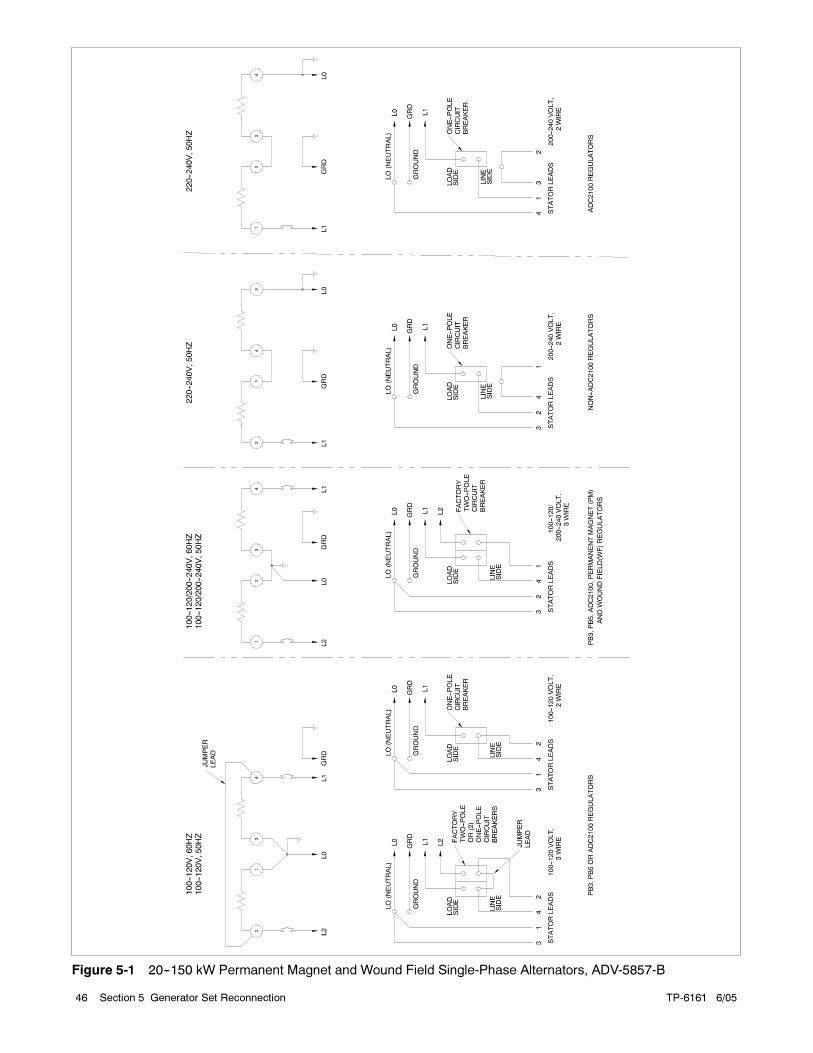
TP-6161 6/0546 Section 5 Generator Set Reconnection
Figure 5-1 20--150 kW Permanent Magnet and Wound Field Single-Phase Alternators, ADV-5857-B
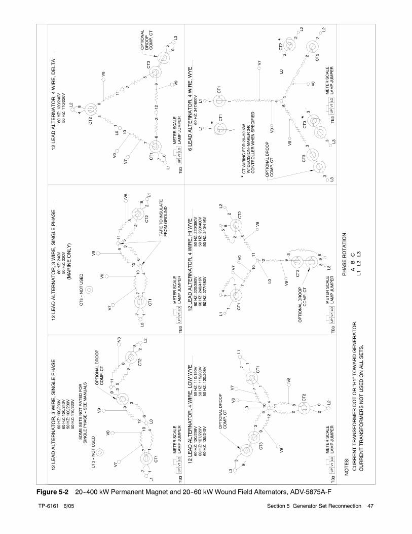
TP-6161 6/05 47Section 5 Generator Set Reconnection
Figure 5-2 20--400 kW Permanent Magnet and 20--60 kW Wound Field Alternators, ADV-5875A-F
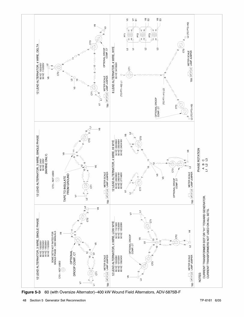
TP-6161 6/0548 Section 5 Generator Set Reconnection
Figure 5-3 60 (with Oversize Alternator)--400 kW Wound Field Alternators, ADV-5875B-F
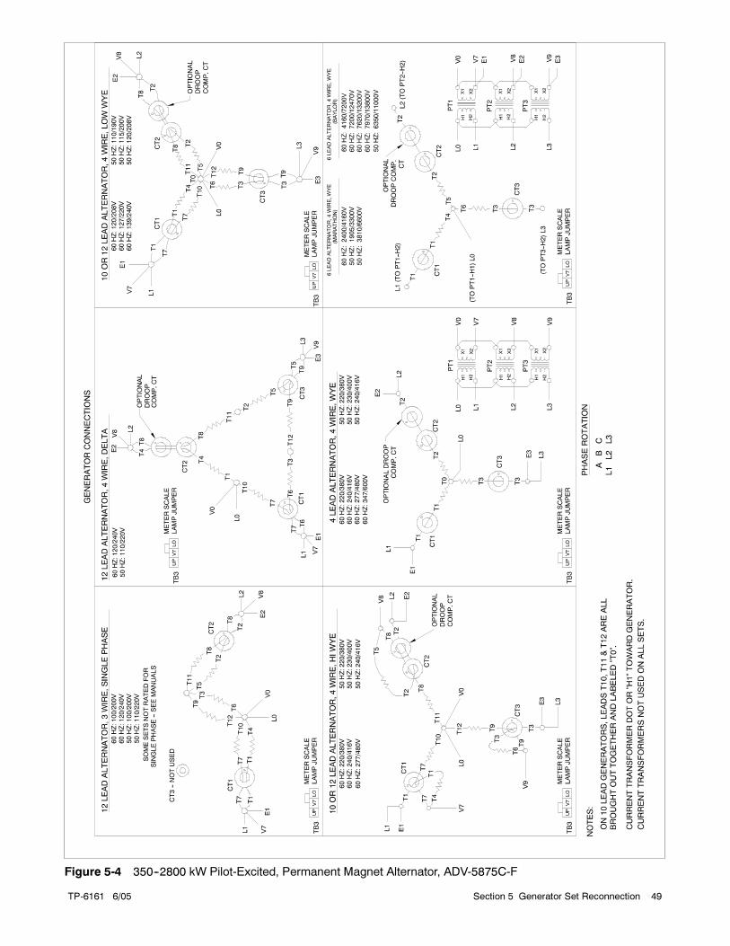
TP-6161 6/05 49Section 5 Generator Set Reconnection
Figure 5-4 350--2800 kW Pilot-Excited, Permanent Magnet Alternator, ADV-5875C-F
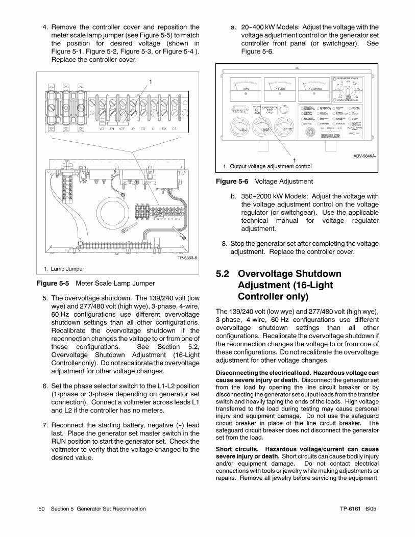
TP-6161 6/0550 Section 5 Generator Set Reconnection
4. Remove the controller cover and reposition the
meter scale lamp jumper (see Figure 5-5) to match
the position for desired voltage (shown in
Figure 5-1, Figure 5-2, Figure 5-3, or Figure 5-4 ).
Replace the controller cover.
TP-5353-6
1
1. Lamp Jumper
Figure 5-5 Meter Scale Lamp Jumper
5. The overvoltage shutdown. The 139/240 volt (low
wye) and 277/480 volt (high wye), 3-phase, 4-wire,
60 Hz configurations use different overvoltage
shutdown settings than all other configurations.
Recalibrate the overvoltage shutdown if the
reconnection changes the voltage to or from one of
these configurations. See Section 5.2,
Overvoltage Shutdown Adjustment (16-Light
Controller only). Do not recalibrate the overvoltage
adjustment for other voltage changes.
6. Set the phase selector switch to the L1-L2 position
(1-phase or 3-phase depending on generator set
connection). Connect a voltmeter across leads L1
and L2 if the controller has no meters.
7. Reconnect the starting battery, negative (--) lead
last. Place the generator set master switch in the
RUN position to start the generator set. Check the
voltmeter to verify that the voltage changed to the
desired value.
a. 20--400 kWModels: Adjust the voltage with the
voltage adjustment control on the generator set
controller front panel (or switchgear). See
Figure 5-6.
ADV-5849A-
11. Output voltage adjustment control
EMERGENCY
STOP
ONLY
OFF/RESET
PREALARMHIGH ENGINETEMPERATURE
PREALARMLOW OILPRESSURE
LOW WATERTEMPERATURE
LOW FUEL
HIGH ENGINETEMPERATURE
LOW OILPRESSURE
EMERGENCYSTOP
OVERSPEED
AUXILIARYFAULT
BATTERYCHARGER FAULT
LOW BATTERYVOLTAGE
OVERCRANK
AUXILIARYPREALARM
AIRDAMPER
SYSTEMREADY
GENERATORSWITCHNOT IN AUTO
NORMALSILENCE
LAMP TEST
ALARMAUTORUN
HERTZ A--C VOLTS A--C AMPERES
BATTERYWATERTEMP
OILPRESS
0 0 0 0 0TOTAL HOURS
LOWER METER SCALES
3OFF1
UPPER METER SCALES
AMPSVOLTS
L0--L1L3
L3--L1
L2L1--L2
L1L1--L2
L1L1--L2
L2L2--L3
SVOLTAGE
ADJUST
O
Figure 5-6 Voltage Adjustment
b. 350--2000 kW Models: Adjust the voltage with
the voltage adjustment control on the voltage
regulator (or switchgear). Use the applicable
technical manual for voltage regulator
adjustment.
8. Stop the generator set after completing the voltage
adjustment. Replace the controller cover.
5.2 Overvoltage Shutdown
Adjustment (16-Light
Controller only)
The 139/240 volt (low wye) and 277/480 volt (high wye),
3-phase, 4-wire, 60 Hz configurations use different
overvoltage shutdown settings than all other
configurations. Recalibrate the overvoltage shutdown if
the reconnection changes the voltage to or from one of
these configurations. Do not recalibrate the overvoltage
adjustment for other voltage changes.
Disconnecting theelectrical load. Hazardous voltagecan
cause severe injury or death. Disconnect the generator setfrom the load by opening the line circuit breaker or bydisconnecting the generator set output leads from the transferswitch and heavily taping the ends of the leads. High voltagetransferred to the load during testing may cause personalinjury and equipment damage. Do not use the safeguard
circuit breaker in place of the line circuit breaker. Thesafeguard circuit breaker does not disconnect the generatorset from the load.
Short circuits. Hazardous voltage/current can causesevere injury or death. Short circuits can cause bodily injuryand/or equipment damage. Do not contact electrical
connections with tools or jewelry whilemaking adjustments orrepairs. Remove all jewelry before servicing the equipment.
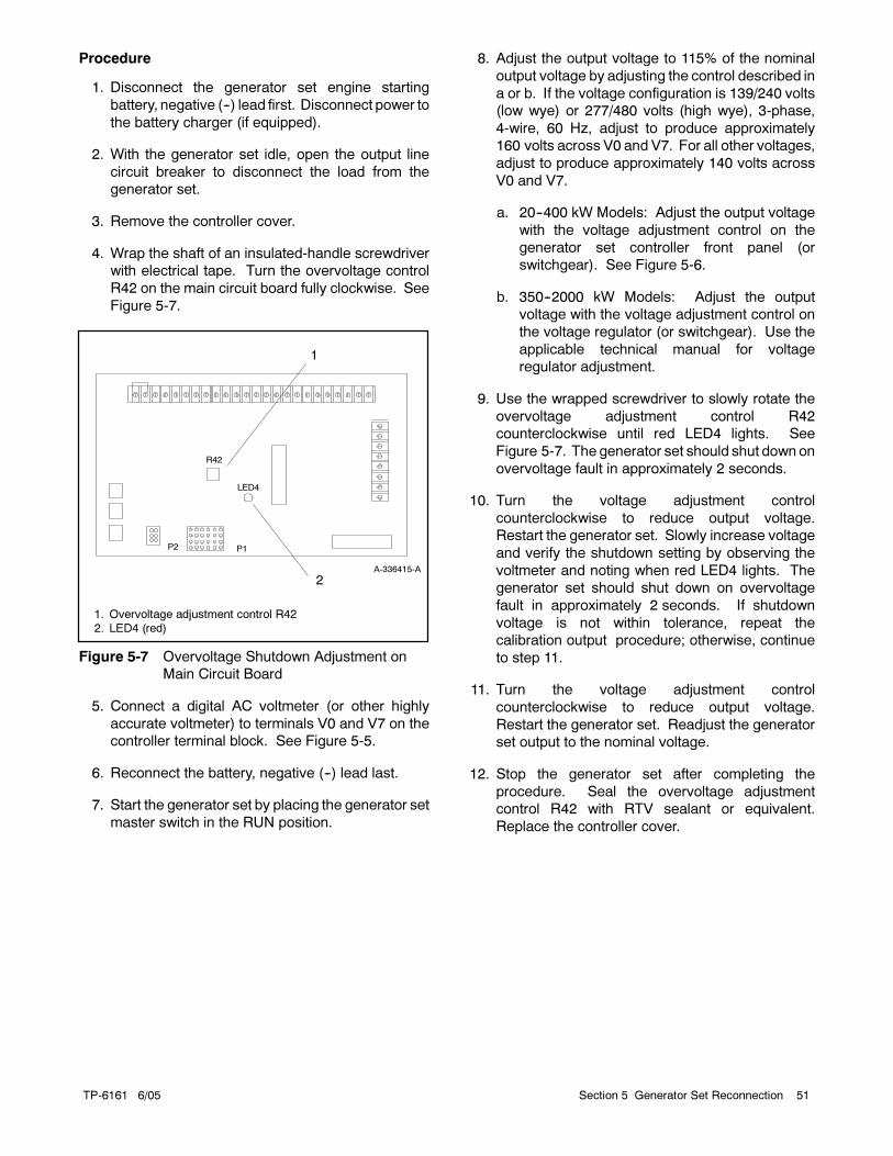
TP-6161 6/05 51Section 5 Generator Set Reconnection
Procedure
1. Disconnect the generator set engine starting
battery, negative (--) lead first. Disconnect power to
the battery charger (if equipped).
2. With the generator set idle, open the output line
circuit breaker to disconnect the load from the
generator set.
3. Remove the controller cover.
4. Wrap the shaft of an insulated-handle screwdriver
with electrical tape. Turn the overvoltage control
R42 on the main circuit board fully clockwise. See
Figure 5-7.
P1P2
A-336415-A
2
R42
LED4
1. Overvoltage adjustment control R42
2. LED4 (red)
1
Figure 5-7 Overvoltage Shutdown Adjustment on
Main Circuit Board
5. Connect a digital AC voltmeter (or other highly
accurate voltmeter) to terminals V0 and V7 on the
controller terminal block. See Figure 5-5.
6. Reconnect the battery, negative (--) lead last.
7. Start the generator set by placing the generator set
master switch in the RUN position.
8. Adjust the output voltage to 115% of the nominal
output voltage by adjusting the control described in
a or b. If the voltage configuration is 139/240 volts
(low wye) or 277/480 volts (high wye), 3-phase,
4-wire, 60 Hz, adjust to produce approximately
160 volts across V0 and V7. For all other voltages,
adjust to produce approximately 140 volts across
V0 and V7.
a. 20--400 kW Models: Adjust the output voltage
with the voltage adjustment control on the
generator set controller front panel (or
switchgear). See Figure 5-6.
b. 350--2000 kW Models: Adjust the output
voltage with the voltage adjustment control on
the voltage regulator (or switchgear). Use the
applicable technical manual for voltage
regulator adjustment.
9. Use the wrapped screwdriver to slowly rotate the
overvoltage adjustment control R42
counterclockwise until red LED4 lights. See
Figure 5-7. The generator set should shut downon
overvoltage fault in approximately 2 seconds.
10. Turn the voltage adjustment control
counterclockwise to reduce output voltage.
Restart the generator set. Slowly increase voltage
and verify the shutdown setting by observing the
voltmeter and noting when red LED4 lights. The
generator set should shut down on overvoltage
fault in approximately 2 seconds. If shutdown
voltage is not within tolerance, repeat the
calibration output procedure; otherwise, continue
to step 11.
11. Turn the voltage adjustment control
counterclockwise to reduce output voltage.
Restart the generator set. Readjust the generator
set output to the nominal voltage.
12. Stop the generator set after completing the
procedure. Seal the overvoltage adjustment
control R42 with RTV sealant or equivalent.
Replace the controller cover.

TP-6161 6/0552 Section 5 Generator Set Reconnection
Notes
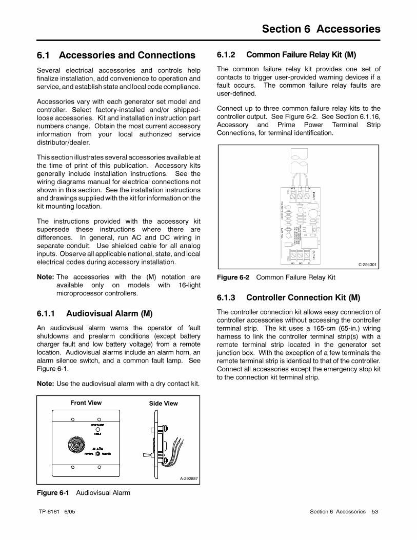
TP-6161 6/05 53Section 6 Accessories
Section 6 Accessories
6.1 Accessories and Connections
Several electrical accessories and controls help
finalize installation, add convenience to operation and
service, and establish state and local code compliance.
Accessories vary with each generator set model and
controller. Select factory-installed and/or shipped-
loose accessories. Kit and installation instruction part
numbers change. Obtain the most current accessory
information from your local authorized service
distributor/dealer.
This section illustrates several accessories available at
the time of print of this publication. Accessory kits
generally include installation instructions. See the
wiring diagrams manual for electrical connections not
shown in this section. See the installation instructions
and drawings suppliedwith the kit for information on the
kit mounting location.
The instructions provided with the accessory kit
supersede these instructions where there are
differences. In general, run AC and DC wiring in
separate conduit. Use shielded cable for all analog
inputs. Observe all applicable national, state, and local
electrical codes during accessory installation.
Note: The accessories with the (M) notation are
available only on models with 16-light
microprocessor controllers.
6.1.1 Audiovisual Alarm (M)
An audiovisual alarm warns the operator of fault
shutdowns and prealarm conditions (except battery
charger fault and low battery voltage) from a remote
location. Audiovisual alarms include an alarm horn, an
alarm silence switch, and a common fault lamp. See
Figure 6-1.
Note: Use the audiovisual alarm with a dry contact kit.
Front View Side View
A-292887
Figure 6-1 Audiovisual Alarm
6.1.2 Common Failure Relay Kit (M)
The common failure relay kit provides one set of
contacts to trigger user-provided warning devices if a
fault occurs. The common failure relay faults are
user-defined.
Connect up to three common failure relay kits to the
controller output. See Figure 6-2. See Section 6.1.16,
Accessory and Prime Power Terminal Strip
Connections, for terminal identification.
C-294301
Figure 6-2 Common Failure Relay Kit
6.1.3 Controller Connection Kit (M)
The controller connection kit allows easy connection of
controller accessories without accessing the controller
terminal strip. The kit uses a 165-cm (65-in.) wiring
harness to link the controller terminal strip(s) with a
remote terminal strip located in the generator set
junction box. With the exception of a few terminals the
remote terminal strip is identical to that of the controller.
Connect all accessories except the emergency stop kit
to the connection kit terminal strip.
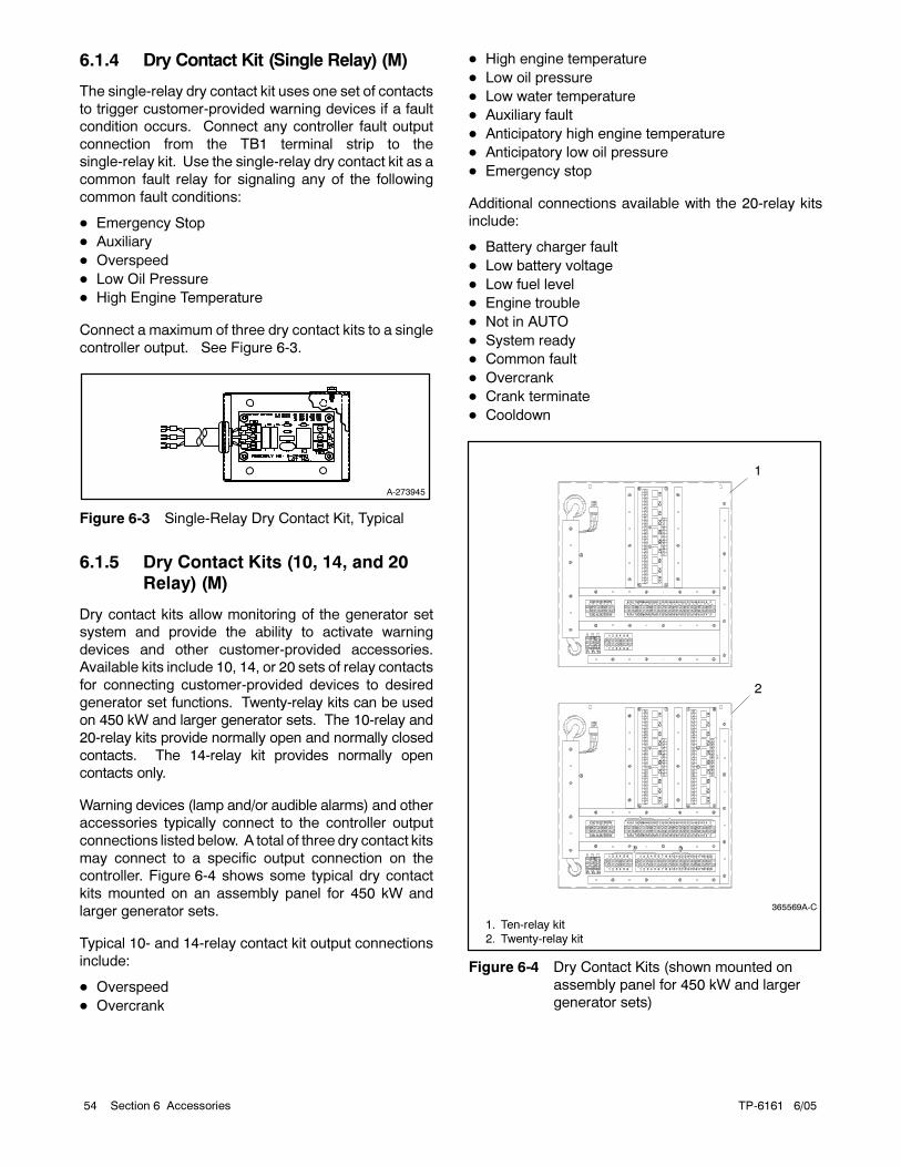
TP-6161 6/0554 Section 6 Accessories
6.1.4 Dry Contact Kit (Single Relay) (M)
The single-relay dry contact kit uses one set of contacts
to trigger customer-provided warning devices if a fault
condition occurs. Connect any controller fault output
connection from the TB1 terminal strip to the
single-relay kit. Use the single-relay dry contact kit as a
common fault relay for signaling any of the following
common fault conditions:
Emergency Stop
Auxiliary
Overspeed
Low Oil Pressure
High Engine Temperature
Connect a maximum of three dry contact kits to a single
controller output. See Figure 6-3.
A-273945
Figure 6-3 Single-Relay Dry Contact Kit, Typical
6.1.5 Dry Contact Kits (10, 14, and 20
Relay) (M)
Dry contact kits allow monitoring of the generator set
system and provide the ability to activate warning
devices and other customer-provided accessories.
Available kits include 10, 14, or 20 sets of relay contacts
for connecting customer-provided devices to desired
generator set functions. Twenty-relay kits can be used
on 450 kW and larger generator sets. The 10-relay and
20-relay kits provide normally open and normally closed
contacts. The 14-relay kit provides normally open
contacts only.
Warning devices (lamp and/or audible alarms) and other
accessories typically connect to the controller output
connections listed below. A total of three dry contact kits
may connect to a specific output connection on the
controller. Figure 6-4 shows some typical dry contact
kits mounted on an assembly panel for 450 kW and
larger generator sets.
Typical 10- and 14-relay contact kit output connections
include:
Overspeed
Overcrank
High engine temperature
Low oil pressure
Low water temperature
Auxiliary fault
Anticipatory high engine temperature
Anticipatory low oil pressure
Emergency stop
Additional connections available with the 20-relay kits
include:
Battery charger fault
Low battery voltage
Low fuel level
Engine trouble
Not in AUTO
System ready
Common fault
Overcrank
Crank terminate
Cooldown
K7
70C
70C
242A707NC1C2C0 C3
6541 32
F1 F3F2
21 43 5 6
70C0 C2C1 C3 7N 42A2
4 3616335 406260 80 4138 362612 3932A4870R56 32
6332A5670R 48 2612 3839 6036 4180 62 3235 40
K10
K9
K8
61 4 3
K6
K5
K4
K3
K2
K1
S
1. Ten-relay kit
2. Twenty-relay kit
365569A-C
K7
K7
70C
70C
242A707NC1C2C0 C3
6541 32
F1 F3F2
21 43 5 6
70C0 C2C1 C3 7N 42A2
4 3616335 406260 80 4138 362612 3932A4870R56 32
17
171516121110 13765 8 91 2 43 14
21 43 65 87 109 111213141516
201819
1918 20
6332A5670R 48 2612 3839 6036 4180 62 3235 40
K10
K9
K8
61 4 3
K10
K9
K8
K6
K5
K4
K3
K2
K1
K6
K5
K4
K3
K2
K1
S
M N
1
2
Figure 6-4 Dry Contact Kits (shown mounted on
assembly panel for 450 kW and larger
generator sets)
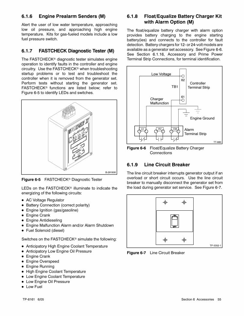
TP-6161 6/05 55Section 6 Accessories
6.1.6 Engine Prealarm Senders (M)
Alert the user of low water temperature, approaching
low oil pressure, and approaching high engine
temperature. Kits for gas-fueled models include a low
fuel pressure switch.
6.1.7 FASTCHECK Diagnostic Tester (M)
The FASTCHECK diagnostic tester simulates engine
operation to identify faults in the controller and engine
circuitry. Use the FASTCHECK when troubleshooting
startup problems or to test and troubleshoot the
controller when it is removed from the generator set.
Perform tests without starting the generator set.
FASTCHECK functions are listed below; refer to
Figure 6-5 to identify LEDs and switches.
B-291930
Figure 6-5 FASTCHECK Diagnostic Tester
LEDs on the FASTCHECK illuminate to indicate the
energizing of the following circuits:
AC Voltage Regulator
Battery Connection (correct polarity)
Engine Ignition (gas/gasoline)
Engine Crank
Engine Antidieseling
Engine Malfunction Alarm and/or Alarm Shutdown
Fuel Solenoid (diesel)
Switches on the FASTCHECK simulate the following:
Anticipatory High Engine Coolant Temperature
Anticipatory Low Engine Oil Pressure
Engine Crank
Engine Overspeed
Engine Running
High Engine Coolant Temperature
Low Engine Coolant Temperature
Low Engine Oil Pressure
Low Fuel
6.1.8 Float/Equalize Battery Charger Kit
with Alarm Option (M)
The float/equalize battery charger with alarm option
provides battery charging to the engine starting
battery(ies) and connects to the controller for fault
detection. Battery chargers for 12- or 24-volt models are
available as a generator set accessory. See Figure 6-6.
See Section 6.1.16, Accessory and Prime Power
Terminal Strip Connections, for terminal identification.
ControllerTerminal Strip
Low Voltage
ChargerMalfunction
AlarmTerminal Strip
LV HV CM
TT-680
TB1
62
61
Engine Ground
Figure 6-6 Float/Equalize Battery Charger
Connections
6.1.9 Line Circuit Breaker
The line circuit breaker interrupts generator output if an
overload or short circuit occurs. Use the line circuit
breaker to manually disconnect the generator set from
the load during generator set service. See Figure 6-7.
TP-5352-1
Figure 6-7 Line Circuit Breaker
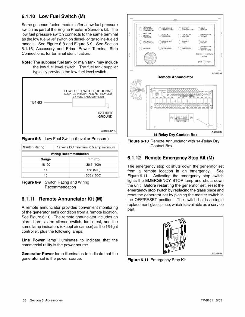
TP-6161 6/0556 Section 6 Accessories
6.1.10 Low Fuel Switch (M)
Some gaseous-fueled models offer a low fuel pressure
switch as part of the Engine Prealarm Senders kit. The
low fuel pressure switch connects to the same terminal
as the low fuel level switch on diesel- or gasoline-fueled
models. See Figure 6-8 and Figure 6-9. See Section
6.1.16, Accessory and Prime Power Terminal Strip
Connections, for terminal identification.
Note: The subbase fuel tank or main tank may include
the low fuel level switch. The fuel tank supplier
typically provides the low fuel level switch.
GM16088A-A
TB1-63
Figure 6-8 Low Fuel Switch (Level or Pressure)
Switch Rating 12 volts DC minimum, 0.5 amp minimum
Wiring Recommendation
Gauge mm (ft.)
18--20 30.5 (100)
14 153 (500)
10 305 (1000)
Figure 6-9 Switch Rating and Wiring
Recommendation
6.1.11 Remote Annunciator Kit (M)
A remote annunciator provides convenient monitoring
of the generator set’s condition from a remote location.
See Figure 6-10. The remote annunciator includes an
alarm horn, alarm silence switch, lamp test, and the
same lamp indicators (except air damper) as the 16-light
controller, plus the following lamps:
Line Power lamp illuminates to indicate that the
commercial utility is the power source.
Generator Power lamp illuminates to indicate that the
generator set is the power source.
Remote Annunciator
14-Relay Dry Contact BoxA-293983
A-258782
NO C CNO CNO CNO CNO CNO CNO CNO CNO CNO CNO CNO CNO CNOK1 K2 K3 K4 K5 K6 K7 K8 K9 K10 K11 K12 K13 K14
INPUTCONTACT RATINGS: 10A@120VAC RES. LOAD.01A@28VDC MIN.10A@28VDC MAX.
PCB ASSY A--320639
LOT NO.
42A 2 K1 K2 K3 K4 K5 K6 K7 K8 K9 K10K11 K13K14K12
10 AMP
42B
FBA--1
P
Figure 6-10 Remote Annunciator with 14-Relay Dry
Contact Box
6.1.12 Remote Emergency Stop Kit (M)
The emergency stop kit shuts down the generator set
from a remote location in an emergency. See
Figure 6-11. Activating the emergency stop switch
lights the EMERGENCY STOP lamp and shuts down
the unit. Before restarting the generator set, reset the
emergency stop switch by replacing the glass piece and
reset the generator set by placing the master switch in
the OFF/RESET position. The switch holds a single
replacement glass piece, which is available as a service
part.
A-222654
Figure 6-11 Emergency Stop Kit
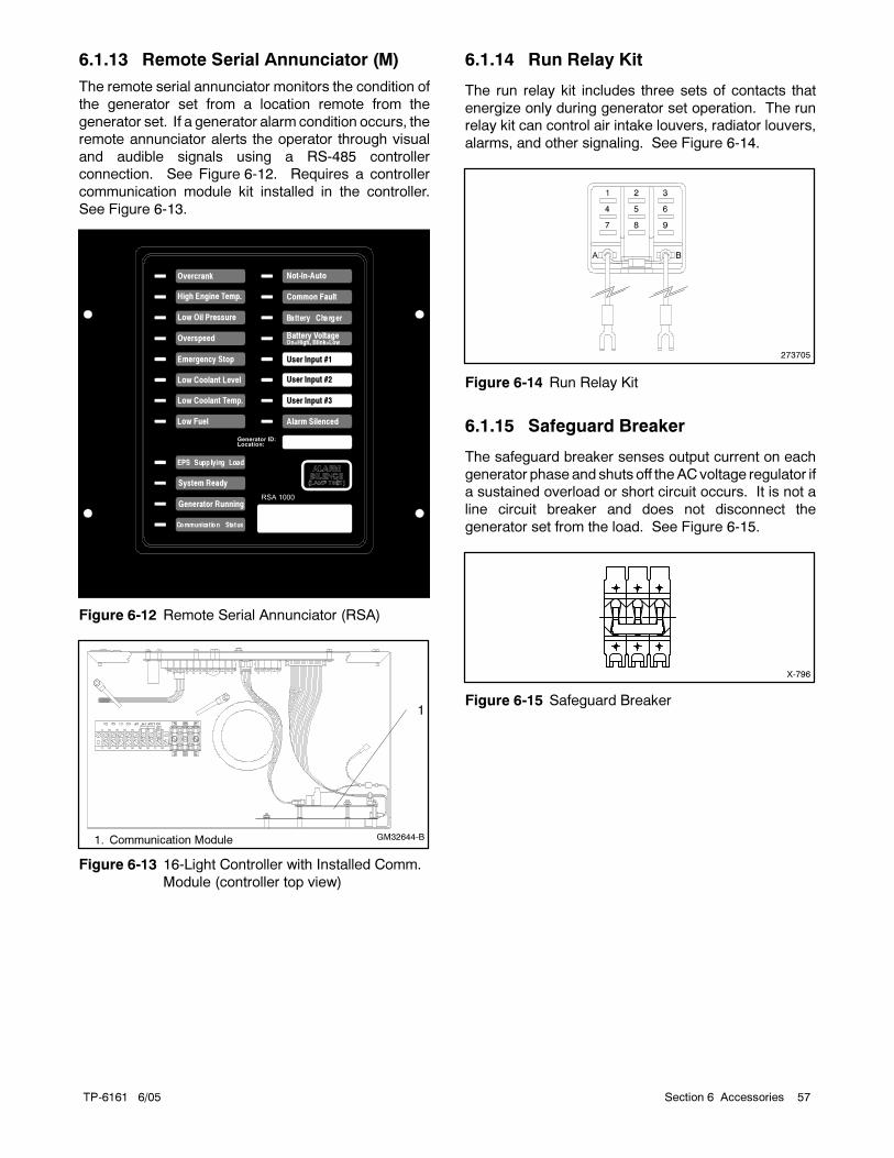
TP-6161 6/05 57Section 6 Accessories
6.1.13 Remote Serial Annunciator (M)
The remote serial annunciator monitors the condition of
the generator set from a location remote from the
generator set. If a generator alarm condition occurs, the
remote annunciator alerts the operator through visual
and audible signals using a RS-485 controller
connection. See Figure 6-12. Requires a controller
communication module kit installed in the controller.
See Figure 6-13.
Overcrank
High Engine Temp.
Low Oil Pressure
Overspeed
Emergency Stop
Low Coolant Level
Low Coolant Temp.
Low Fuel
System Ready
Generator Running
Not-In-Auto
Common Fault
Battery Voltage
Alarm Silenced
On=High, Blink=Low
User Input #1
User Input #2
User Input #3
Figure 6-12 Remote Serial Annunciator (RSA)
1. Communication Module GM32644-B
1
Figure 6-13 16-Light Controller with Installed Comm.
Module (controller top view)
6.1.14 Run Relay Kit
The run relay kit includes three sets of contacts that
energize only during generator set operation. The run
relay kit can control air intake louvers, radiator louvers,
alarms, and other signaling. See Figure 6-14.
273705
Figure 6-14 Run Relay Kit
6.1.15 Safeguard Breaker
The safeguard breaker senses output current on each
generator phase and shuts off theACvoltage regulator if
a sustained overload or short circuit occurs. It is not a
line circuit breaker and does not disconnect the
generator set from the load. See Figure 6-15.
X-796
Figure 6-15 Safeguard Breaker
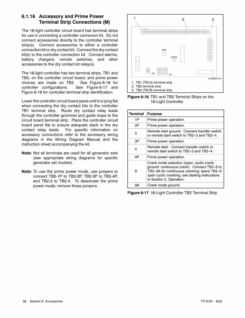
TP-6161 6/0558 Section 6 Accessories
6.1.16 Accessory and Prime Power
Terminal Strip Connections (M)
The 16-light controller circuit board has terminal strips
for use in connecting a controller connecton kit. Do not
connect accessories directly to the controller terminal
strip(s). Connect accessories to either a controller
connection kit or dry contact kit. Connect the dry contact
kit(s) to the controller connection kit. Connect alarms,
battery chargers, remote switches, and other
accessories to the dry contact kit relay(s).
The 16-light controller has two terminal strips, TB1 and
TB2, on the controller circuit board, and prime power
choices are made on TB2. See Figure 6-16 for
controller configurations. See Figure 6-17 and
Figure 6-18 for controller terminal strip identification.
Lower the controller circuit board panel until it is lying flat
when connecting the dry contact kits to the controller
TB1 terminal strip. Route dry contact relay leads
through the controller grommet and guide loops to the
circuit board terminal strip. Place the controller circuit
board panel flat to ensure adequate slack in the dry
contact relay leads. For specific information on
accessory connections refer to the accessory wiring
diagrams in the Wiring Diagram Manual and the
instruction sheet accompanying the kit.
Note: Not all terminals are used for all generator sets
(see appropriate wiring diagrams for specific
generator set models).
Note: To use the prime power mode, use jumpers to
connect TB2-1P to TB2-2P, TB2-3P to TB2-4P,
and TB2-3 to TB2-4. To deactivate the prime
power mode, remove these jumpers.
1 23
P1P2
A-336415-A
R41
LED4
1. TB1 (TB1A) terminal strip
2. TB2 terminal strip3. TB3 (TB1B) terminal strip
Figure 6-16 TB1 and TB2 Terminal Strips on the
16-Light Controller
Terminal Purpose
1P Prime power operation.
2P Prime power operation.
3Remote start ground. Connect transfer switchor remote start switch to TB2--3 and TB2--4.
3P Prime power operation.
4Remote start. Connect transfer switch orremote start switch to TB2--3 and TB2--4.
4P Prime power operation.
9
Crank mode selection (open: cyclic crank,ground: continuous crank). Connect TB2--9 toTB2--9A for continuous cranking; leave TB2--9open cyclic cranking; see starting instructionsin Section 2, Operation.
9A Crank mode ground.
Figure 6-17 16-Light Controller TB2 Terminal Strip
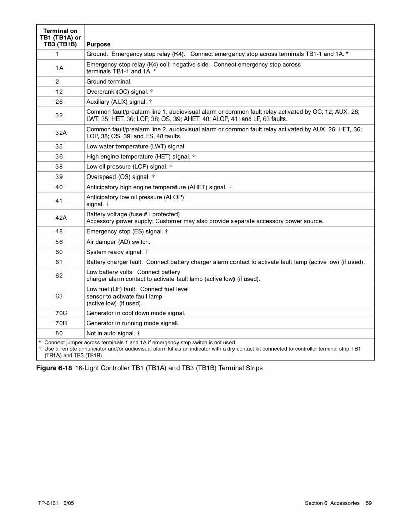
TP-6161 6/05 59Section 6 Accessories
Terminal onTB1 (TB1A) orTB3 (TB1B) Purpose
1 Ground. Emergency stop relay (K4). Connect emergency stop across terminals TB1-1 and 1A. *
1AEmergency stop relay (K4) coil; negative side. Connect emergency stop acrossterminals TB1-1 and 1A. *
2 Ground terminal.
12 Overcrank (OC) signal.
26 Auxiliary (AUX) signal.
32Common fault/prealarm line 1. audiovisual alarm or common fault relay activated by OC, 12; AUX, 26;LWT, 35; HET, 36; LOP, 38; OS, 39; AHET, 40; ALOP, 41; and LF, 63 faults.
32ACommon fault/prealarm line 2. audiovisual alarm or common fault relay activated by AUX, 26; HET, 36;LOP, 38; OS, 39; and ES, 48 faults.
35 Low water temperature (LWT) signal.
36 High engine temperature (HET) signal.
38 Low oil pressure (LOP) signal.
39 Overspeed (OS) signal.
40 Anticipatory high engine temperature (AHET) signal.
41Anticipatory low oil pressure (ALOP)signal.
42ABattery voltage (fuse #1 protected).Accessory power supply; Customer may also provide separate accessory power source.
48 Emergency stop (ES) signal.
56 Air damper (AD) switch.
60 System ready signal.
61 Battery charger fault. Connect battery charger alarm contact to activate fault lamp (active low) (if used).
62Low battery volts. Connect batterycharger alarm contact to activate fault lamp (active low) (if used).
63Low fuel (LF) fault. Connect fuel levelsensor to activate fault lamp(active low) (if used).
70C Generator in cool down mode signal.
70R Generator in running mode signal.
80 Not in auto signal.
* Connect jumper across terminals 1 and 1A if emergency stop switch is not used. Use a remote annunciator and/or audiovisual alarm kit as an indicator with a dry contact kit connected to controller terminal strip TB1
(TB1A) and TB3 (TB1B).
Figure 6-18 16-Light Controller TB1 (TB1A) and TB3 (TB1B) Terminal Strips

TP-6161 6/0560 Section 6 Accessories
Notes
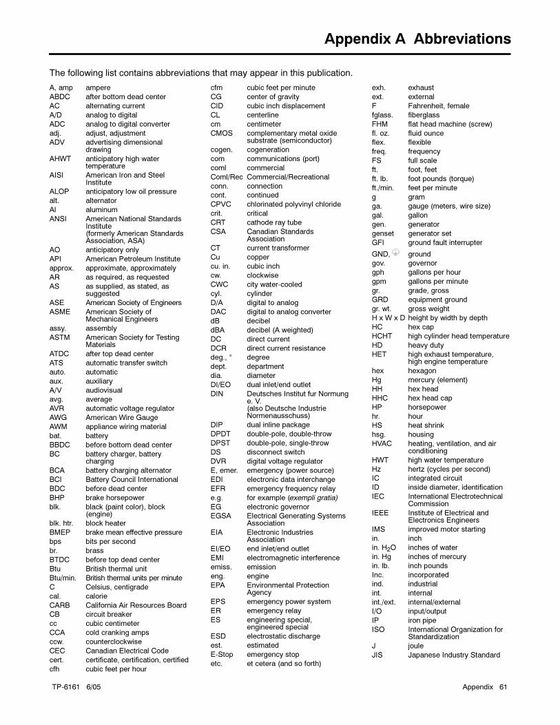
TP-6161 6/05 Appendix 61
Appendix A Abbreviations
The following list contains abbreviations that may appear in this publication.
A, amp ampere
ABDC after bottom dead center
AC alternating current
A/D analog to digital
ADC analog to digital converter
adj. adjust, adjustment
ADV advertising dimensionaldrawing
AHWT anticipatory high watertemperature
AISI American Iron and SteelInstitute
ALOP anticipatory low oil pressure
alt. alternator
Al aluminum
ANSI American National StandardsInstitute(formerly American StandardsAssociation, ASA)
AO anticipatory only
API American Petroleum Institute
approx. approximate, approximately
AR as required, as requested
AS as supplied, as stated, assuggested
ASE American Society of Engineers
ASME American Society ofMechanical Engineers
assy. assembly
ASTM American Society for TestingMaterials
ATDC after top dead center
ATS automatic transfer switch
auto. automatic
aux. auxiliary
A/V audiovisual
avg. average
AVR automatic voltage regulator
AWG American Wire Gauge
AWM appliance wiring material
bat. battery
BBDC before bottom dead center
BC battery charger, batterycharging
BCA battery charging alternator
BCI Battery Council International
BDC before dead center
BHP brake horsepower
blk. black (paint color), block(engine)
blk. htr. block heater
BMEP brake mean effective pressure
bps bits per second
br. brass
BTDC before top dead center
Btu British thermal unit
Btu/min. British thermal units per minute
C Celsius, centigrade
cal. calorie
CARB California Air Resources Board
CB circuit breaker
cc cubic centimeter
CCA cold cranking amps
ccw. counterclockwise
CEC Canadian Electrical Code
cert. certificate, certification, certified
cfh cubic feet per hour
cfm cubic feet per minute
CG center of gravity
CID cubic inch displacement
CL centerline
cm centimeter
CMOS complementary metal oxidesubstrate (semiconductor)
cogen. cogeneration
com communications (port)
coml commercial
Coml/Rec Commercial/Recreational
conn. connection
cont. continued
CPVC chlorinated polyvinyl chloride
crit. critical
CRT cathode ray tube
CSA Canadian StandardsAssociation
CT current transformer
Cu copper
cu. in. cubic inch
cw. clockwise
CWC city water-cooled
cyl. cylinder
D/A digital to analog
DAC digital to analog converter
dB decibel
dBA decibel (A weighted)
DC direct current
DCR direct current resistance
deg., ° degree
dept. department
dia. diameter
DI/EO dual inlet/end outlet
DIN Deutsches Institut fur Normunge. V.(also Deutsche IndustrieNormenausschuss)
DIP dual inline package
DPDT double-pole, double-throw
DPST double-pole, single-throw
DS disconnect switch
DVR digital voltage regulator
E, emer. emergency (power source)
EDI electronic data interchange
EFR emergency frequency relay
e.g. for example (exempli gratia)
EG electronic governor
EGSA Electrical Generating SystemsAssociation
EIA Electronic IndustriesAssociation
EI/EO end inlet/end outlet
EMI electromagnetic interference
emiss. emission
eng. engine
EPA Environmental ProtectionAgency
EPS emergency power system
ER emergency relay
ES engineering special,engineered special
ESD electrostatic discharge
est. estimated
E-Stop emergency stop
etc. et cetera (and so forth)
exh. exhaust
ext. external
F Fahrenheit, female
fglass. fiberglass
FHM flat head machine (screw)
fl. oz. fluid ounce
flex. flexible
freq. frequency
FS full scale
ft. foot, feet
ft. lb. foot pounds (torque)
ft./min. feet per minute
g gram
ga. gauge (meters, wire size)
gal. gallon
gen. generator
genset generator set
GFI ground fault interrupter
GND, ground
gov. governor
gph gallons per hour
gpm gallons per minute
gr. grade, gross
GRD equipment ground
gr. wt. gross weight
H x W x D height by width by depth
HC hex cap
HCHT high cylinder head temperature
HD heavy duty
HET high exhaust temperature,high engine temperature
hex hexagon
Hg mercury (element)
HH hex head
HHC hex head cap
HP horsepower
hr. hour
HS heat shrink
hsg. housing
HVAC heating, ventilation, and airconditioning
HWT high water temperature
Hz hertz (cycles per second)
IC integrated circuit
ID inside diameter, identification
IEC International ElectrotechnicalCommission
IEEE Institute of Electrical andElectronics Engineers
IMS improved motor starting
in. inch
in. H2O inches of water
in. Hg inches of mercury
in. lb. inch pounds
Inc. incorporated
ind. industrial
int. internal
int./ext. internal/external
I/O input/output
IP iron pipe
ISO International Organization forStandardization
J joule
JIS Japanese Industry Standard
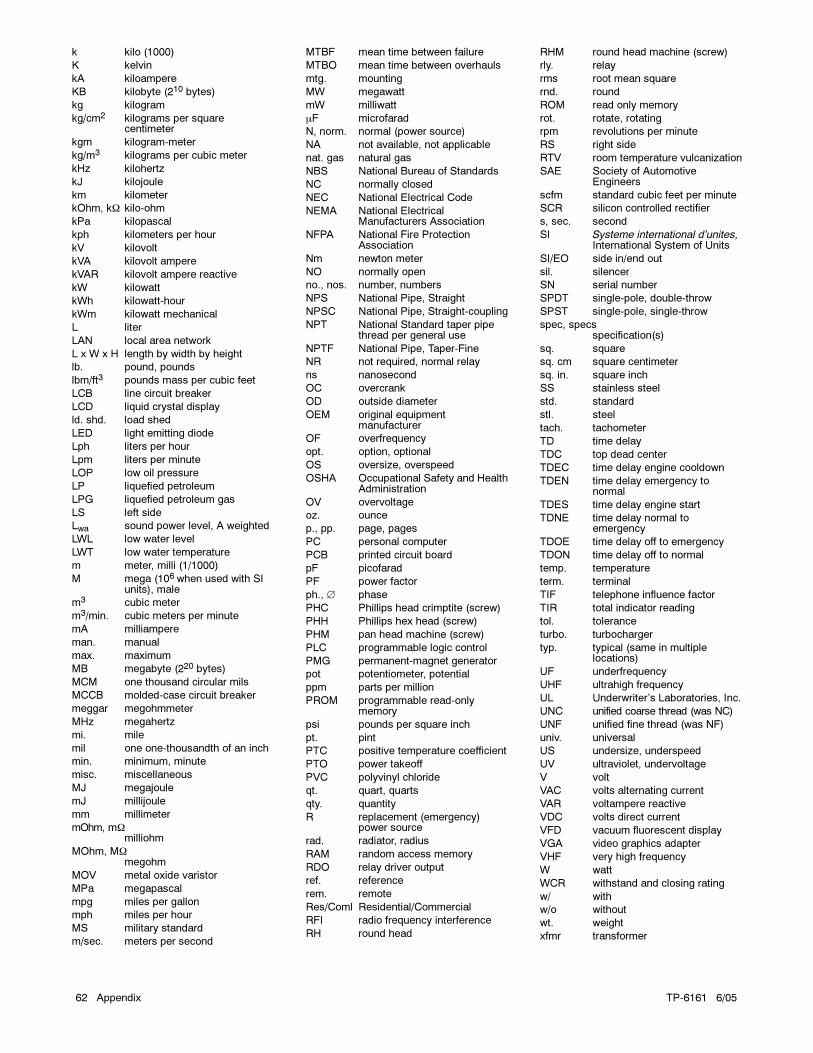
TP-6161 6/0562 Appendix
k kilo (1000)
K kelvin
kA kiloampere
KB kilobyte (210 bytes)
kg kilogram
kg/cm2 kilograms per squarecentimeter
kgm kilogram-meter
kg/m3 kilograms per cubic meter
kHz kilohertz
kJ kilojoule
km kilometer
kOhm, kΩ kilo-ohm
kPa kilopascal
kph kilometers per hour
kV kilovolt
kVA kilovolt ampere
kVAR kilovolt ampere reactive
kW kilowatt
kWh kilowatt-hour
kWm kilowatt mechanical
L liter
LAN local area network
L x W x H length by width by height
lb. pound, pounds
lbm/ft3 pounds mass per cubic feet
LCB line circuit breaker
LCD liquid crystal display
ld. shd. load shed
LED light emitting diode
Lph liters per hour
Lpm liters per minute
LOP low oil pressure
LP liquefied petroleum
LPG liquefied petroleum gas
LS left side
Lwa sound power level, A weighted
LWL low water level
LWT low water temperature
m meter, milli (1/1000)
M mega (106 when used with SIunits), male
m3 cubic meter
m3/min. cubic meters per minute
mA milliampere
man. manual
max. maximum
MB megabyte (220 bytes)
MCM one thousand circular mils
MCCB molded-case circuit breaker
meggar megohmmeter
MHz megahertz
mi. mile
mil one one-thousandth of an inch
min. minimum, minute
misc. miscellaneous
MJ megajoule
mJ millijoule
mm millimeter
mOhm, mΩmilliohm
MOhm, MΩmegohm
MOV metal oxide varistor
MPa megapascal
mpg miles per gallon
mph miles per hour
MS military standard
m/sec. meters per second
MTBF mean time between failure
MTBO mean time between overhauls
mtg. mounting
MW megawatt
mW milliwatt
μF microfarad
N, norm. normal (power source)
NA not available, not applicable
nat. gas natural gas
NBS National Bureau of Standards
NC normally closed
NEC National Electrical Code
NEMA National ElectricalManufacturers Association
NFPA National Fire ProtectionAssociation
Nm newton meter
NO normally open
no., nos. number, numbers
NPS National Pipe, Straight
NPSC National Pipe, Straight-coupling
NPT National Standard taper pipethread per general use
NPTF National Pipe, Taper-Fine
NR not required, normal relay
ns nanosecond
OC overcrank
OD outside diameter
OEM original equipmentmanufacturer
OF overfrequency
opt. option, optional
OS oversize, overspeed
OSHA Occupational Safety and HealthAdministration
OV overvoltage
oz. ounce
p., pp. page, pages
PC personal computer
PCB printed circuit board
pF picofarad
PF power factor
ph., ∅ phase
PHC Phillips head crimptite (screw)
PHH Phillips hex head (screw)
PHM pan head machine (screw)
PLC programmable logic control
PMG permanent-magnet generator
pot potentiometer, potential
ppm parts per million
PROM programmable read-onlymemory
psi pounds per square inch
pt. pint
PTC positive temperature coefficient
PTO power takeoff
PVC polyvinyl chloride
qt. quart, quarts
qty. quantity
R replacement (emergency)power source
rad. radiator, radius
RAM random access memory
RDO relay driver output
ref. reference
rem. remote
Res/Coml Residential/Commercial
RFI radio frequency interference
RH round head
RHM round head machine (screw)
rly. relay
rms root mean square
rnd. round
ROM read only memory
rot. rotate, rotating
rpm revolutions per minute
RS right side
RTV room temperature vulcanization
SAE Society of AutomotiveEngineers
scfm standard cubic feet per minute
SCR silicon controlled rectifier
s, sec. second
SI Systeme international d’unites,International System of Units
SI/EO side in/end out
sil. silencer
SN serial number
SPDT single-pole, double-throw
SPST single-pole, single-throw
spec, specsspecification(s)
sq. square
sq. cm square centimeter
sq. in. square inch
SS stainless steel
std. standard
stl. steel
tach. tachometer
TD time delay
TDC top dead center
TDEC time delay engine cooldown
TDEN time delay emergency tonormal
TDES time delay engine start
TDNE time delay normal toemergency
TDOE time delay off to emergency
TDON time delay off to normal
temp. temperature
term. terminal
TIF telephone influence factor
TIR total indicator reading
tol. tolerance
turbo. turbocharger
typ. typical (same in multiplelocations)
UF underfrequency
UHF ultrahigh frequency
UL Underwriter’s Laboratories, Inc.
UNC unified coarse thread (was NC)
UNF unified fine thread (was NF)
univ. universal
US undersize, underspeed
UV ultraviolet, undervoltage
V volt
VAC volts alternating current
VAR voltampere reactive
VDC volts direct current
VFD vacuum fluorescent display
VGA video graphics adapter
VHF very high frequency
W watt
WCR withstand and closing rating
w/ with
w/o without
wt. weight
xfmr transformer


2004, 2005 by Kohler Co. All rights reserved.
TP-6161 6/05b
KOHLER CO. Kohler, Wisconsin 53044Phone 920-565-3381, Fax 920-459-1646For the nearest sales/service outlet in theUS and Canada, phone 1-800-544-2444KohlerPowerSystems.com
Kohler Power SystemsAsia Pacific Headquarters7 Jurong Pier RoadSingapore 619159Phone (65) 6264-6422, Fax (65) 6264-6455