Embed Size (px)
Citation preview
User Manual
• Built for harsh environments. • Support Gigabit speeds for high-aggregation links.• Scalable, reliable, and flexible.
Industrial Managed Gigabit Ethernet Switch
LEH2004A-4GSFP
Order toll-free in the U.S.: Call 877-877-BBOX (outside U.S. call 724-746-5500)FREE technical support 24 hours a day, 7 days a week: Call 724-746-5500 or fax 724-746-0746www.blackbox.com • [email protected]
Customer Support
Information
724-746-5500 | blackbox.com Page 2
Trademarks Used in this Manual
We‘re here to help! If you have any questions about your application or our products, contact Black Box Tech Support at 724-746-5500
or go to blackbox.com and click on “Talk to Black Box.”You’ll be live with one of our technical experts in less than 60 seconds.
Trademarks Used in this Manual
Black Box and the Double Diamond logo are registered trademarks of BB Technologies, Inc.
Any other trademarks mentioned in this manual are acknowledged to be the property of the trademark owners.
Disclaimer:Black Box Network Services shall not be liable for damages of any kind, including, but not limited to, punitive, consequential or cost of cover damages, resulting from any errors in the product information or specifications set forth in this document and Black Box Network Services may revise this document at any time without notice.

724-746-5500 | blackbox.com Page 3
FCC and IC RFI Statements
Federal Communications Commission and Industry Canada Radio Frequency Interference Statements
This equipment generates, uses, and can radiate radio-frequency energy, and if not installed and used properly, that is, in strict accordance with the manufacturer’s instructions, may cause inter ference to radio communication. It has been tested and found to comply with the limits for a Class A computing device in accordance with the specifications in Subpart B of Part 15 of FCC rules, which are designed to provide reasonable protection against such interference when the equipment is operated in a commercial environment. Operation of this equipment in a residential area is likely to cause interference, in which case the user at his own expense will be required to take whatever measures may be necessary to correct the interference.
Changes or modifications not expressly approved by the party responsible for compliance could void the user’s authority to operate the equipment.
This digital apparatus does not exceed the Class A limits for radio noise emis sion from digital apparatus set out in the Radio Interference Regulation of Industry Canada.
Le présent appareil numérique n’émet pas de bruits radioélectriques dépassant les limites applicables aux appareils numériques de la classe A prescrites dans le Règlement sur le brouillage radioélectrique publié par Industrie Canada.
724-746-5500 | blackbox.com Page 4
NOM Statement
Instrucciones de Seguridad(Normas Oficiales Mexicanas Electrical Safety Statement)1. Todas las instrucciones de seguridad y operación deberán ser leídas antes de que el aparato eléctrico sea operado.
2. Las instrucciones de seguridad y operación deberán ser guardadas para referencia futura.
3. Todas las advertencias en el aparato eléctrico y en sus instrucciones de operación deben ser respetadas.
4. Todas las instrucciones de operación y uso deben ser seguidas.
5. El aparato eléctrico no deberá ser usado cerca del agua—por ejemplo, cerca de la tina de baño, lavabo, sótano mojado o cerca de una alberca, etc.
6. El aparato eléctrico debe ser usado únicamente con carritos o pedestales que sean recomendados por el fabricante.
7. El aparato eléctrico debe ser montado a la pared o al techo sólo como sea recomendado por el fabricante.
8. Servicio—El usuario no debe intentar dar servicio al equipo eléctrico más allá a lo descrito en las instrucciones de operación. Todo otro servicio deberá ser referido a personal de servicio calificado.
9. El aparato eléctrico debe ser situado de tal manera que su posición no interfiera su uso. La colocación del aparato eléctrico sobre una cama, sofá, alfombra o superficie similar puede bloquea la ventilación, no se debe colocar en libreros o gabinetes que impidan el flujo de aire por los orificios de ventilación.
10. El equipo eléctrico deber ser situado fuera del alcance de fuentes de calor como radiadores, registros de calor, estufas u otros aparatos (incluyendo amplificadores) que producen calor.
11. El aparato eléctrico deberá ser connectado a una fuente de poder sólo del tipo descrito en el instructivo de operación, o como se indique en el aparato.
12. Precaución debe ser tomada de tal manera que la tierra fisica y la polarización del equipo no sea eliminada.
13. Los cables de la fuente de poder deben ser guiados de tal manera que no sean pisados ni pellizcados por objetos colocados sobre o contra ellos, poniendo particular atención a los contactos y receptáculos donde salen del aparato.
14. El equipo eléctrico debe ser limpiado únicamente de acuerdo a las recomendaciones del fabricante.
15. En caso de existir, una antena externa deberá ser localizada lejos de las lineas de energia.
16. El cable de corriente deberá ser desconectado del cuando el equipo no sea usado por un largo periodo de tiempo.
17. Cuidado debe ser tomado de tal manera que objectos liquidos no sean derramados sobre la cubierta u orificios de ventilación.
18. Servicio por personal calificado deberá ser provisto cuando: A: El cable de poder o el contacto ha sido dañado; u B: Objectos han caído o líquido ha sido derramado dentro del aparato; o C: El aparato ha sido expuesto a la lluvia; o D: El aparato parece no operar normalmente o muestra un cambio en su desempeño; o E: El aparato ha sido tirado o su cubierta ha sido dañada.
724-746-5500 | blackbox.com Page 5
Table of Contents
Table of Contents
1. Specifications .........................................................................................................................................................................8
2. Overview .............................................................................................................................................................................10 2.1 Introduction .................................................................................................................................................................10 2.2 Features .......................................................................................................................................................................10 2.2.1 Software .............................................................................................................................................................10 2.2.2 Hardware ...........................................................................................................................................................10 2.3 What's Included .......................................................................................................................................................... 11 2.4 Hardware Description .................................................................................................................................................. 12 Industrial Managed Gigabit Ethernet Switch - 4-Port RJ-45, 4-Port Combo RJ-45/SFP (LEH2004A-4GSFP) ............... 12
3. Hardware Installation ...........................................................................................................................................................14 3.1 Installing the Switch on a DIN Rail ...............................................................................................................................14 3.2 Installing the Switch on a Wall .................................................................................................................................... 15 3.3 Cables .........................................................................................................................................................................16 3.3.1 Ethernet Cables ..................................................................................................................................................16 3.3.2 Console Cable .................................................................................................................................................... 17 3.4 Compatible SFPs ..........................................................................................................................................................18
4. Web Management ..............................................................................................................................................................19 4.1 Configuration by Web Browser ...................................................................................................................................19 4.1.1 About Web-based Management .......................................................................................................................19 4.1.2 System Information .............................................................................................................................................20 4.1.3 Front Panel ..........................................................................................................................................................21 4.1.4 Basic Setting .......................................................................................................................................................21 4.1.4.1 Switch setting ...........................................................................................................................................21 4.1.4.2 Admin Password ......................................................................................................................................22 4.1.4.3 IP Setting ................................................................................................................................................. 23 4.1.4.4 Time Setting .............................................................................................................................................23 4.1.4.5 LLDP .........................................................................................................................................................26 4.1.4.6 Modbus TCP .............................................................................................................................................27 4.1.4.7 Auto Provision ..........................................................................................................................................27 4.1.4.8 Backup and Restore ..................................................................................................................................28 4.1.4.9 Upgrade Firmware ....................................................................................................................................29 4.1.5 Redundancy ........................................................................................................................................................30 4.1.5.1 MRP ..........................................................................................................................................................30 4.1.5.2 B-Ring ......................................................................................................................................................31 4.1.5.3 Open-Ring ................................................................................................................................................32 4.1.5.4 B-Chain ....................................................................................................................................................33 4.1.5.5 RSTP—Repeater .......................................................................................................................................34 4.1.5.6 Fast Recovery ............................................................................................................................................34 4.1.5.7 RSTP .........................................................................................................................................................35 4.1.5.8 MSTP ........................................................................................................................................................37 4.1.6 Multicast ............................................................................................................................................................. 41 4.1.6.1 IGMP Snooping ........................................................................................................................................................ 41 4.1.6.2 MVR .........................................................................................................................................................42 4.1.6.3 Static Multicast Filtering ............................................................................................................................42 4.1.7 Port Setting .........................................................................................................................................................43 4.1.7.1 Port Control...............................................................................................................................................43 4.1.7.2 Port Status ................................................................................................................................................44
724-746-5500 | blackbox.com Page 6
Table of Contents
4.1.7.3 Port Alias ...................................................................................................................................................44 4.1.7.4 Rate Limit ..................................................................................................................................................44 4.1.7.5 Port Trunk .................................................................................................................................................45 4.1.7.6 Loop Guard ...............................................................................................................................................47 4.1.8 VLAN ..................................................................................................................................................................47 4.1.8.1 VLAN Configuration – IEEE 802.1Q ...........................................................................................................47 4.1.8.2 VLAN Configuration – Port Based ............................................................................................................49 4.1.9 Traffic Prioritization .............................................................................................................................................50 4.1.9.1 Qos policy .................................................................................................................................................50 4.1.9.2 Port-based priority .................................................................................................................................... 51 4.1.9.3 COS/802.1p .............................................................................................................................................. 51 4.1.9.4 TOS/DSCP .................................................................................................................................................52 4.1.10 DHCP Server ......................................................................................................................................................53 4.1.10.1 DHCP Server—Setting .............................................................................................................................53 4.1.10.2 DHCP Server—Client List ........................................................................................................................54 4.1.10.3 DHCP Server—Port and IP Bindings ........................................................................................................54 4.1.10.4 DHCP Server—DHCP Relay Agent ..........................................................................................................55 4.1.11 SNMP ................................................................................................................................................................56 4.1.11.1 SNMP—Agent Setting .............................................................................................................................56 4.1.11.2 SNMP—Trap Setting ...............................................................................................................................58 4.1.11.3 SNMPV3 ..................................................................................................................................................59 4.1.12 Security .............................................................................................................................................................61 4.1.12.1 Management Security .............................................................................................................................61 4.1.12.2 Static MAC Forwarding ...........................................................................................................................62 4.1.12.3 MAC Blacklist ..........................................................................................................................................63 4.1.12.4 802.1x .....................................................................................................................................................64 4.1.12.5 IP Guard ..................................................................................................................................................66 4.1.13 Warning ............................................................................................................................................................68 4.1.13.1 Fault Alarm ..............................................................................................................................................68 4.1.13.2 System Alarm ..........................................................................................................................................69 4.1.14 Monitor and Diag ..............................................................................................................................................72 4.1.14.1 System Event Log ....................................................................................................................................72 4.1.14.2 MAC Address Table ................................................................................................................................73 4.1.14.3 Port Overview ......................................................................................................................................... 74 4.1.14.4 Port Counters ..........................................................................................................................................75 4.1.14.5 Port Monitoring ......................................................................................................................................76 4.1.14.6 Traffic Monitor ........................................................................................................................................77 4.1.14.7 Ping .........................................................................................................................................................78 4.1.15 Save Configuration ............................................................................................................................................78 4.1.16 Factory Default ..................................................................................................................................................79 4.1.17 System Reboot ..................................................................................................................................................79
5. Command-Line Interface (CLI) Management ......................................................................................................................80 5.1 About CLI Management ..............................................................................................................................................80 5.2 Commands Set List—System Commands Set ..............................................................................................................84 5.3 Commands Set List—Port Commands Set ..................................................................................................................86 5.4 Commands Set List—Trunk command set ..................................................................................................................88 5.5 Commands Set List—VLAN command set ..................................................................................................................89 5.6 Commands Set List—Spanning Tree command set .....................................................................................................90 5.7 Commands Set List—QoS command set .....................................................................................................................91 5.8 Commands Set List—IGMP command set ...................................................................................................................91
724-746-5500 | blackbox.com Page 7
Table of Contents
5.9 Commands Set List—MAC/Filter Table command set .................................................................................................92 5.10 Commands Set List—SNMP command set ..................................................................................................................92 5.11 Commands Set List—Port Mirroring command set .....................................................................................................93 5.12 Commands Set List—802.1x command set .................................................................................................................93 5.13 Commands Set List—TFTP command set ....................................................................................................................94 5.14 Commands Set List—SYSLOG, SMTP, EVENT command set .......................................................................................95 5.15 Commands Set List—SNTP command set ...................................................................................................................96 5.16 Commands Set List— Ring command set ...................................................................................................................97
Appendix A. Time Zones ...........................................................................................................................................................98
724-746-5500 | blackbox.com Page 8
Chapter 1: Specifications
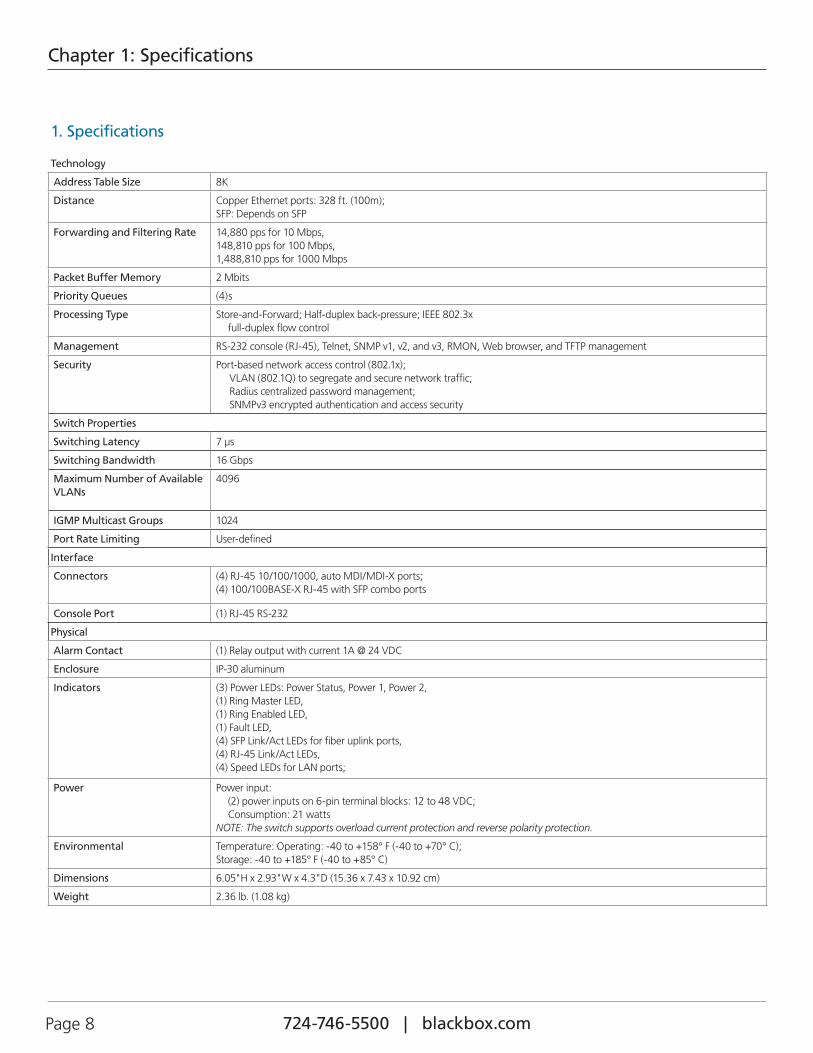
1. Specifications
Technology
Address Table Size 8K
Distance Copper Ethernet ports: 328 ft. (100m);SFP: Depends on SFP
Forwarding and Filtering Rate 14,880 pps for 10 Mbps,148,810 pps for 100 Mbps,1,488,810 pps for 1000 Mbps
Packet Buffer Memory 2 Mbits
Priority Queues (4)s
Processing Type Store-and-Forward; Half-duplex back-pressure; IEEE 802.3x full-duplex flow control
Management RS-232 console (RJ-45), Telnet, SNMP v1, v2, and v3, RMON, Web browser, and TFTP management
Security Port-based network access control (802.1x); VLAN (802.1Q) to segregate and secure network traffic; Radius centralized password management; SNMPv3 encrypted authentication and access security
Switch Properties
Switching Latency 7 µs
Switching Bandwidth 16 Gbps
Maximum Number of Available VLANs
4096
IGMP Multicast Groups 1024
Port Rate Limiting User-defined
Interface
Connectors (4) RJ-45 10/100/1000, auto MDI/MDI-X ports;(4) 100/100BASE-X RJ-45 with SFP combo ports
Console Port (1) RJ-45 RS-232
Physical
Alarm Contact (1) Relay output with current 1A @ 24 VDC
Enclosure IP-30 aluminum
Indicators (3) Power LEDs: Power Status, Power 1, Power 2,(1) Ring Master LED,(1) Ring Enabled LED,(1) Fault LED,(4) SFP Link/Act LEDs for fiber uplink ports,(4) RJ-45 Link/Act LEDs,(4) Speed LEDs for LAN ports;
Power Power input: (2) power inputs on 6-pin terminal blocks: 12 to 48 VDC; Consumption: 21 watts
NOTE: The switch supports overload current protection and reverse polarity protection.
Environmental Temperature: Operating: -40 to +158° F (-40 to +70° C); Storage: -40 to +185° F (-40 to +85° C)
Dimensions 6.05"H x 2.93"W x 4.3"D (15.36 x 7.43 x 10.92 cm)
Weight 2.36 lb. (1.08 kg)
724-746-5500 | blackbox.com Page 9
Chapter 1: Specifications
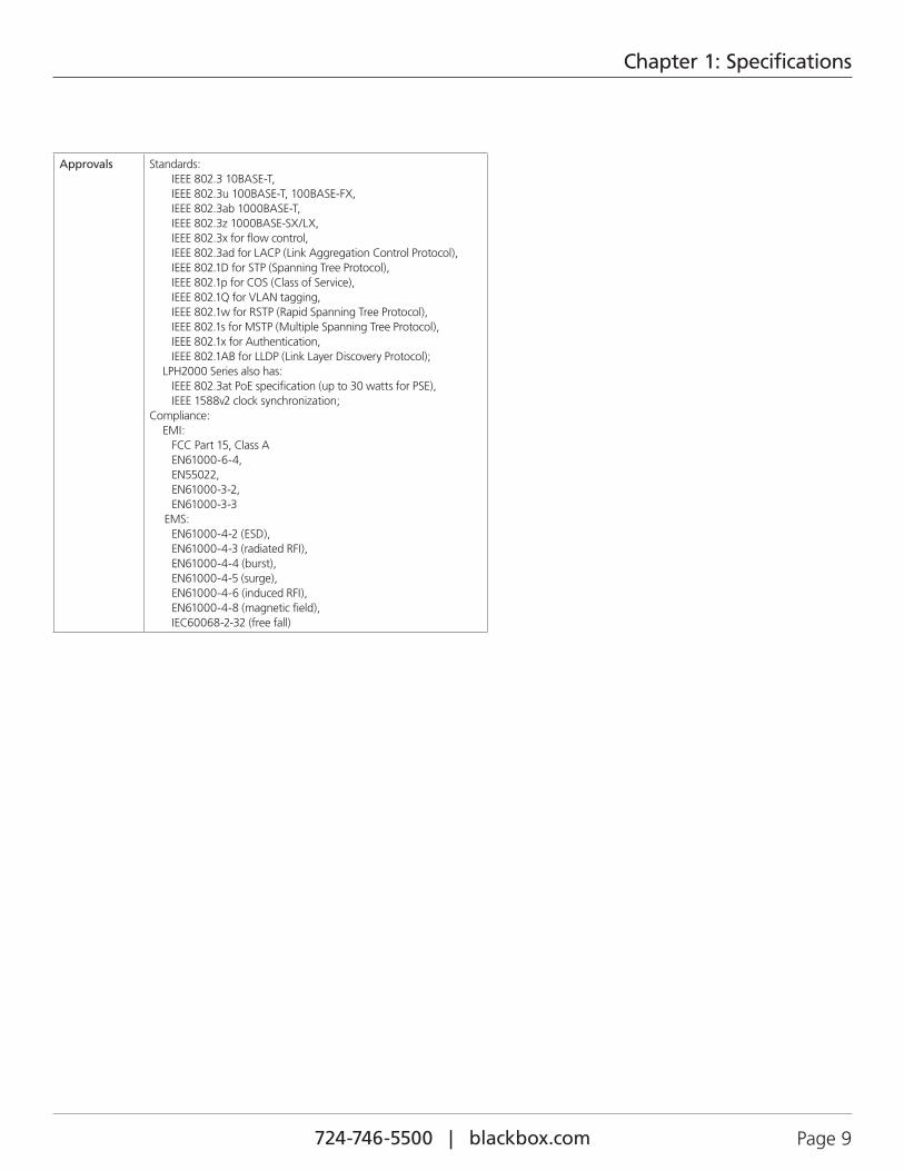
Approvals Standards: IEEE 802.3 10BASE-T, IEEE 802.3u 100BASE-T, 100BASE-FX, IEEE 802.3ab 1000BASE-T, IEEE 802.3z 1000BASE-SX/LX, IEEE 802.3x for flow control, IEEE 802.3ad for LACP (Link Aggregation Control Protocol), IEEE 802.1D for STP (Spanning Tree Protocol), IEEE 802.1p for COS (Class of Service), IEEE 802.1Q for VLAN tagging, IEEE 802.1w for RSTP (Rapid Spanning Tree Protocol), IEEE 802.1s for MSTP (Multiple Spanning Tree Protocol), IEEE 802.1x for Authentication, IEEE 802.1AB for LLDP (Link Layer Discovery Protocol); LPH2000 Series also has: IEEE 802.3at PoE specification (up to 30 watts for PSE), IEEE 1588v2 clock synchronization;
Compliance: EMI: FCC Part 15, Class A EN61000-6-4, EN55022, EN61000-3-2, EN61000-3-3
EMS: EN61000-4-2 (ESD), EN61000-4-3 (radiated RFI), EN61000-4-4 (burst), EN61000-4-5 (surge), EN61000-4-6 (induced RFI), EN61000-4-8 (magnetic field), IEC60068-2-32 (free fall)
724-746-5500 | blackbox.com Page 10
Chapter 2: Overview
2. Overview
2.1 IntroductionThe LEH2004A-4GSFP is a powerful Industrial Managed Gigabit Ethernet Switch. The switch can work in a wide range of temperatures, dusty environments, and humid conditions. You can manage the switches via Web, Telnet, console, or third-party SNMP software, or via the included software utility. Configure multiple switches at the same time and monitor their status.
2.2 Features2.2.1 Software• World’s fastest redundant Ethernet ring: recovery time is less than 20 ms with more than 250 units connected.
• Supports ring coupling, dual homing over redundant Ethernet ring technology.
• Supports SNMPv1/v2c/v3 and RMON and port-based/802.1Q VLAN network management.
• Notifies you of events via email, SNMP trap, and relay output.
• Web-based, Telnet, console, CLI configuration.
• Enable/disable ports, MAC based port security.
• Port based network access control (802.1x).
• Uses VLAN (802.1q) to segregate and secure network traffic.
• Radius centralized password management.
• SNMPv3 encrypted authentication and access security.
• RSTP (802.1w).
• Quality of Service (802.1p) for real-time traffic.
• VLAN (802.1q) with double tagging and GVRP supported.
• IGMP Snooping for multicast filtering.
• Port configuration, status, statistics, mirroring, security.
• Remote Monitoring (RMON).
2.2.2 Hardware Features • Has three redundant DC power inputs.
• Operating temperature is -40 to +158° F (-40 to +70° C), storage temperature is -40 to +185° F (-40 to +85° C).
• Operating humidity is 5% to 95%, non-condensing.
• Casing: IP-30.
• (4) RJ-45 10/100/1000, auto MDI/MDI-X ports; (4) 100/100BASE-X RJ-45 with SFP combo ports
724-746-5500 | blackbox.com Page 11
Chapter 2: Overview
2.3 What’s Included• (1) Industrial Managed Gigabit Ethernet Switch (LEH2004A-4GSFP)
• (8) dust covers (RJ-45)
• (4) dust covers (SFP)
• (5) M3 flat screws
• (1) 6-pin terminal block
• (1) wallmount plate
• (1) console cable RJ-45 to DB9
• (1) 66-mm DIN rail kit (attached)
• (1) Quick Start Guide
To download this user manual from our Web site:
1. Go to www.blackbox.com
2. Enter the part number (LEH2004A-4GSFP) in the search box:
3. Click on the “Resources” tab on the product page, and select the document you wish to download.
If you have any trouble accessing the Black Box site to download the manual, you can contact our Technical Support at 724-746-5500 or [email protected].
724-746-5500 | blackbox.com Page 12
Chapter 2: Overview
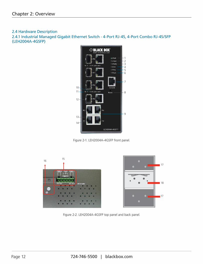
2.4 Hardware Description2.4.1 Industrial Managed Gigabit Ethernet Switch - 4-Port RJ-45, 4-Port Combo RJ-45/SFP (LEH2004A-4GSFP)
1 2 3 4 5 6 7
8
9
10
11
12
13 14
Figure 2-1. LEH2004A-4GSFP front panel.
1516
17
17
18
Figure 2-2. LEH2004A-4GSFP top panel and back panel.
724-746-5500 | blackbox.com Page 13
Chapter 2: Overview
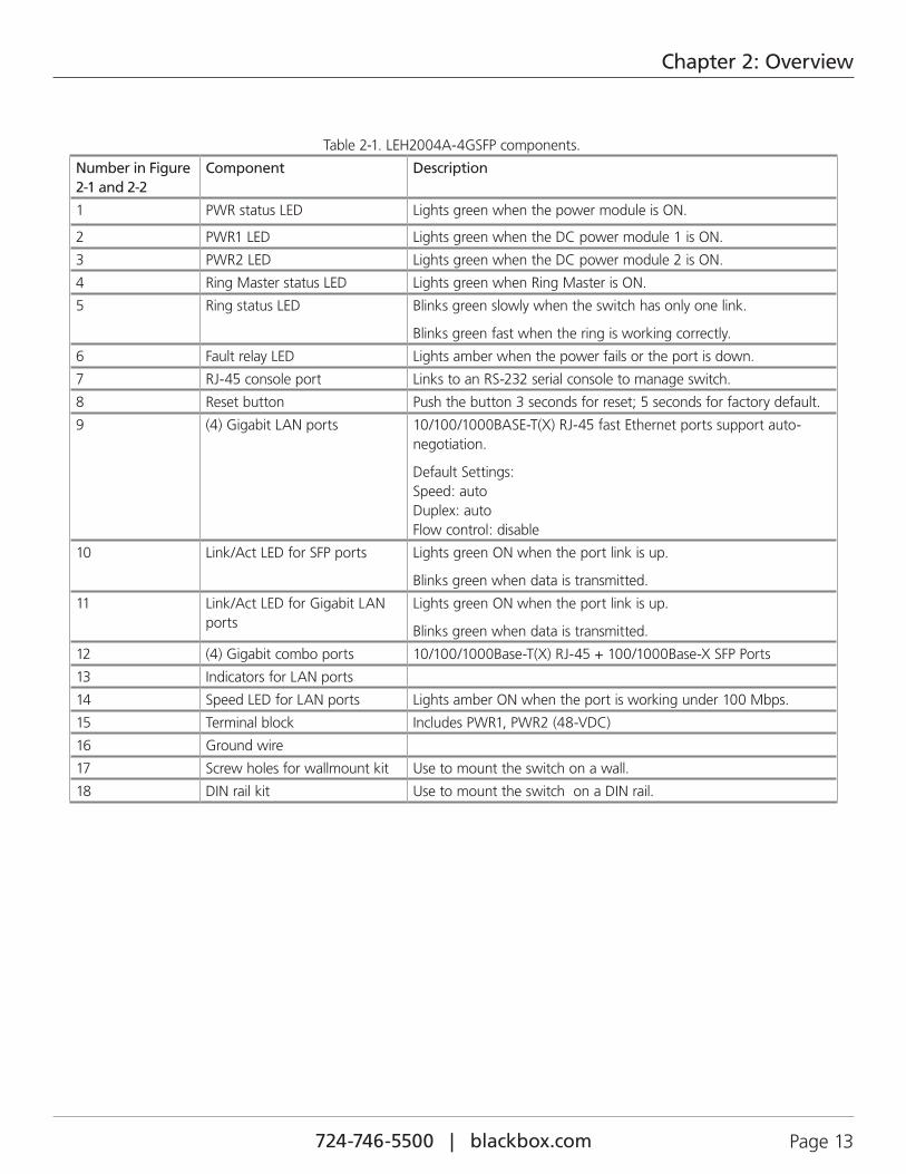
Table 2-1. LEH2004A-4GSFP components.
Number in Figure 2-1 and 2-2
Component Description
1 PWR status LED Lights green when the power module is ON.
2 PWR1 LED Lights green when the DC power module 1 is ON.
3 PWR2 LED Lights green when the DC power module 2 is ON.
4 Ring Master status LED Lights green when Ring Master is ON.
5 Ring status LED Blinks green slowly when the switch has only one link.
Blinks green fast when the ring is working correctly.
6 Fault relay LED Lights amber when the power fails or the port is down.
7 RJ-45 console port Links to an RS-232 serial console to manage switch.
8 Reset button Push the button 3 seconds for reset; 5 seconds for factory default.
9 (4) Gigabit LAN ports 10/100/1000BASE-T(X) RJ-45 fast Ethernet ports support auto-negotiation.
Default Settings: Speed: auto Duplex: auto Flow control: disable
10 Link/Act LED for SFP ports Lights green ON when the port link is up.
Blinks green when data is transmitted.
11 Link/Act LED for Gigabit LAN ports
Lights green ON when the port link is up.
Blinks green when data is transmitted.
12 (4) Gigabit combo ports 10/100/1000Base-T(X) RJ-45 + 100/1000Base-X SFP Ports
13 Indicators for LAN ports
14 Speed LED for LAN ports Lights amber ON when the port is working under 100 Mbps.
15 Terminal block Includes PWR1, PWR2 (48-VDC)
16 Ground wire
17 Screw holes for wallmount kit Use to mount the switch on a wall.
18 DIN rail kit Use to mount the switch on a DIN rail.
724-746-5500 | blackbox.com Page 14
Chapter 3: Hardware Installation
3. Hardware Installation
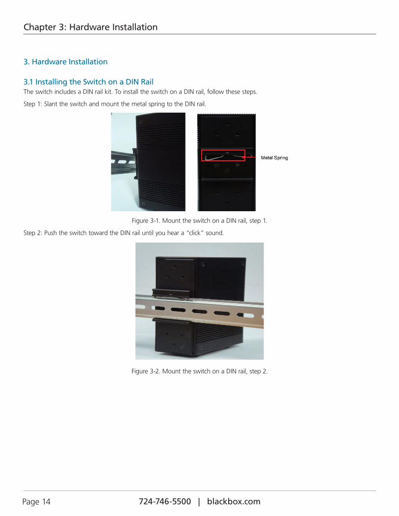
3.1 Installing the Switch on a DIN RailThe switch includes a DIN rail kit. To install the switch on a DIN rail, follow these steps.
Step 1: Slant the switch and mount the metal spring to the DIN rail.
Figure 3-1. Mount the switch on a DIN rail, step 1.
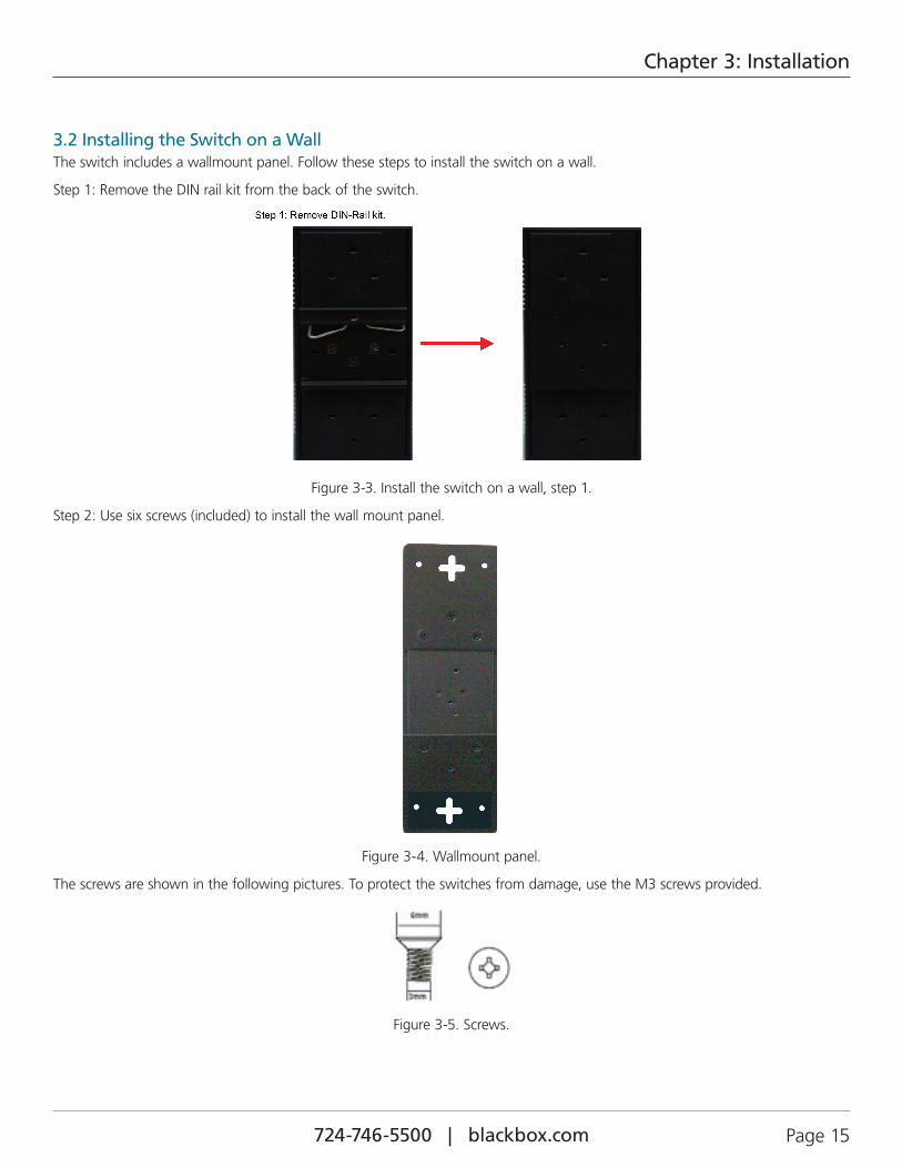
Step 2: Push the switch toward the DIN rail until you hear a “click” sound.
Figure 3-2. Mount the switch on a DIN rail, step 2.
724-746-5500 | blackbox.com Page 15
Chapter 3: Installation
3.2 Installing the Switch on a WallThe switch includes a wallmount panel. Follow these steps to install the switch on a wall.
Step 1: Remove the DIN rail kit from the back of the switch.
Figure 3-3. Install the switch on a wall, step 1.
Step 2: Use six screws (included) to install the wall mount panel.
Figure 3-4. Wallmount panel.
The screws are shown in the following pictures. To protect the switches from damage, use the M3 screws provided.
Figure 3-5. Screws.
724-746-5500 | blackbox.com Page 16
Chapter 3: Hardware Installation
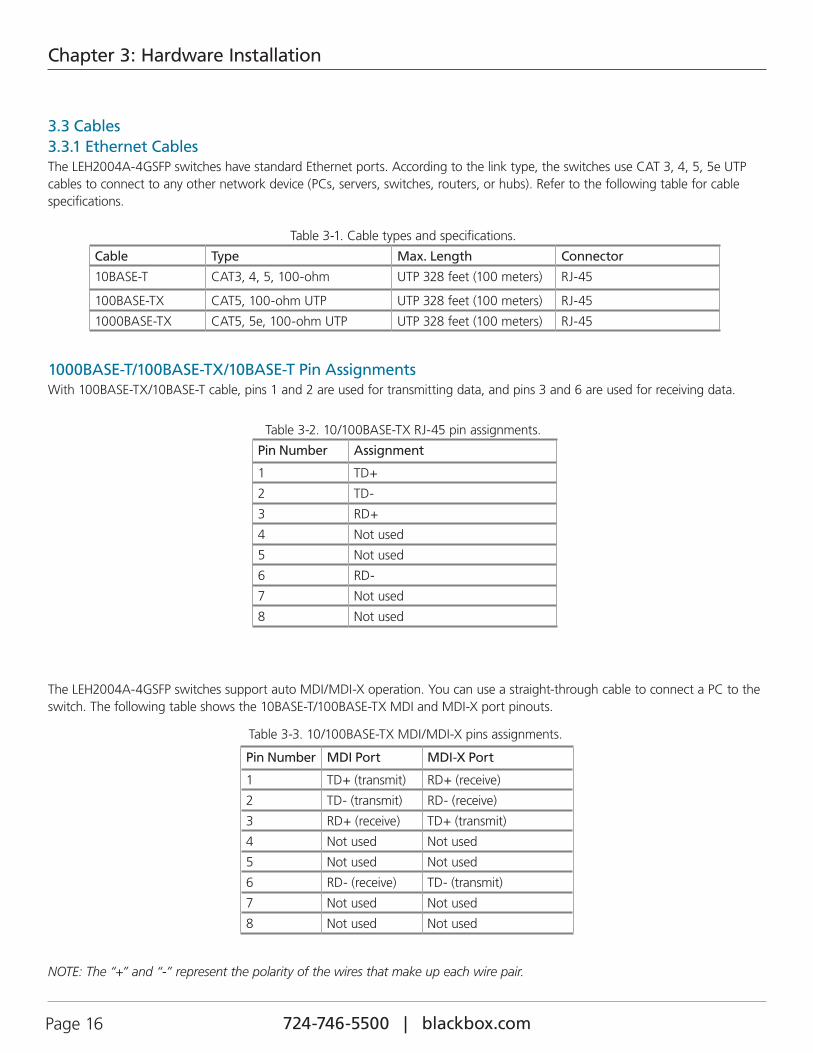
3.3 Cables3.3.1 Ethernet CablesThe LEH2004A-4GSFP switches have standard Ethernet ports. According to the link type, the switches use CAT 3, 4, 5, 5e UTP cables to connect to any other network device (PCs, servers, switches, routers, or hubs). Refer to the following table for cable specifications.
Table 3-1. Cable types and specifications.
Cable Type Max. Length Connector
10BASE-T CAT3, 4, 5, 100-ohm UTP 328 feet (100 meters) RJ-45
100BASE-TX CAT5, 100-ohm UTP UTP 328 feet (100 meters) RJ-45
1000BASE-TX CAT5, 5e, 100-ohm UTP UTP 328 feet (100 meters) RJ-45
1000BASE-T/100BASE-TX/10BASE-T Pin AssignmentsWith 100BASE-TX/10BASE-T cable, pins 1 and 2 are used for transmitting data, and pins 3 and 6 are used for receiving data.
Table 3-2. 10/100BASE-TX RJ-45 pin assignments.
Pin Number Assignment
1 TD+
2 TD-
3 RD+
4 Not used
5 Not used
6 RD-
7 Not used
8 Not used
The LEH2004A-4GSFP switches support auto MDI/MDI-X operation. You can use a straight-through cable to connect a PC to the switch. The following table shows the 10BASE-T/100BASE-TX MDI and MDI-X port pinouts.
Table 3-3. 10/100BASE-TX MDI/MDI-X pins assignments.
Pin Number MDI Port MDI-X Port
1 TD+ (transmit) RD+ (receive)
2 TD- (transmit) RD- (receive)
3 RD+ (receive) TD+ (transmit)
4 Not used Not used
5 Not used Not used
6 RD- (receive) TD- (transmit)
7 Not used Not used
8 Not used Not used
NOTE: The “+” and “-” represent the polarity of the wires that make up each wire pair.
724-746-5500 | blackbox.com Page 17
Chapter 3: Hardware Installation
Table 3-4. 1000BASE-TX MDI/MDI-X Pin Assignments
Pin Number MDI Port MDI-X Port
1 BI_DA+ BI_DB+
2 BI_DA- BI_DB-
3 BI_DB+ BI_DA+
4 BI_DC+ BI_DD+
5 BI_DC- BI_DD-
6 BI_DB- BI_DA-
7 BI_DD+ BI_DC+
8 BI_DD- BI_DC-
NOTE: “+” and “-” signs represent the polarity of the wires that make up each wire pair.
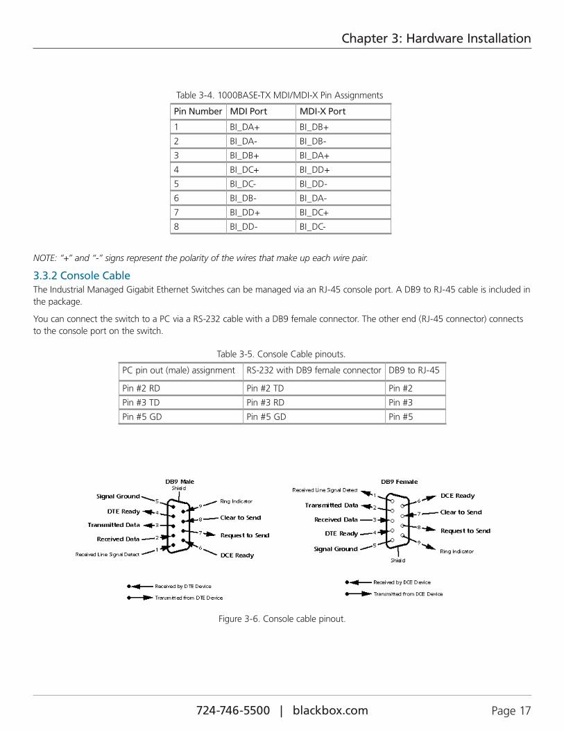
3.3.2 Console CableThe Industrial Managed Gigabit Ethernet Switches can be managed via an RJ-45 console port. A DB9 to RJ-45 cable is included in the package.
You can connect the switch to a PC via a RS-232 cable with a DB9 female connector. The other end (RJ-45 connector) connects to the console port on the switch.
Table 3-5. Console Cable pinouts.
PC pin out (male) assignment RS-232 with DB9 female connector DB9 to RJ-45
Pin #2 RD Pin #2 TD Pin #2
Pin #3 TD Pin #3 RD Pin #3
Pin #5 GD Pin #5 GD Pin #5
Figure 3-6. Console cable pinout.
724-746-5500 | blackbox.com Page 18
Chapter 3: Installation
3.4 Compatible SFPsThe switch has fiber optic ports with SFP connectors. These ports operate uisng multimode (0 to 550 m, 850 nm with 50/125 µm, 62.5/125 µm fiber) cable and in single-mode with LC connector. Remember that the TX port of Switch A should be connected to the RX port of Switch B.
Table 3-6. SFP Modules.
Product Code Description
LFP401 SFP, 155-Mbps Fiber with Extended Diagnostics, 850-nm Multimode, LC, 2 km
LFP402 SFP, 155-Mbps Fiber with Extended Diagnostics, 1310-nm Multimode, LC, 2 km
LFP403 SFP, 155-Mbps Fiber with Extended Diagnostics, 1310-nm, Single-Mode, LC, 30 km
LFP404 SFP, 155-Mbps Fiber with Extended Diagnostics, 1310-nm Single-Mode, Plus, LC, 60 km
LFP411 SFP, 1.25-Gbps Fiber with Extended Diagnostics, 850-nm Multimode, LC, 300 m
LFP412 SFP, 1.25-Gbps Fiber with Extended Diagnostics, 1310-nm Multimode, LC, 2 km
LFP413 SFP, 1.25-Gbps Fiber with Extended Diagnostics, 1310-nm Single-Mode, LC, 10 km
LFP414 SFP, 1.25-Gbps Fiber with Extended Diagnostics, 1310-nm Single-Mode, LC, 30 km
LFP416 SFP with SGMII Interface, 1.25 Gbps, Copper, 10/100/1000BASE-T, Extended Diagnostics
724-746-5500 | blackbox.com Page 19
Chapter 4: Web-Based Browser Management
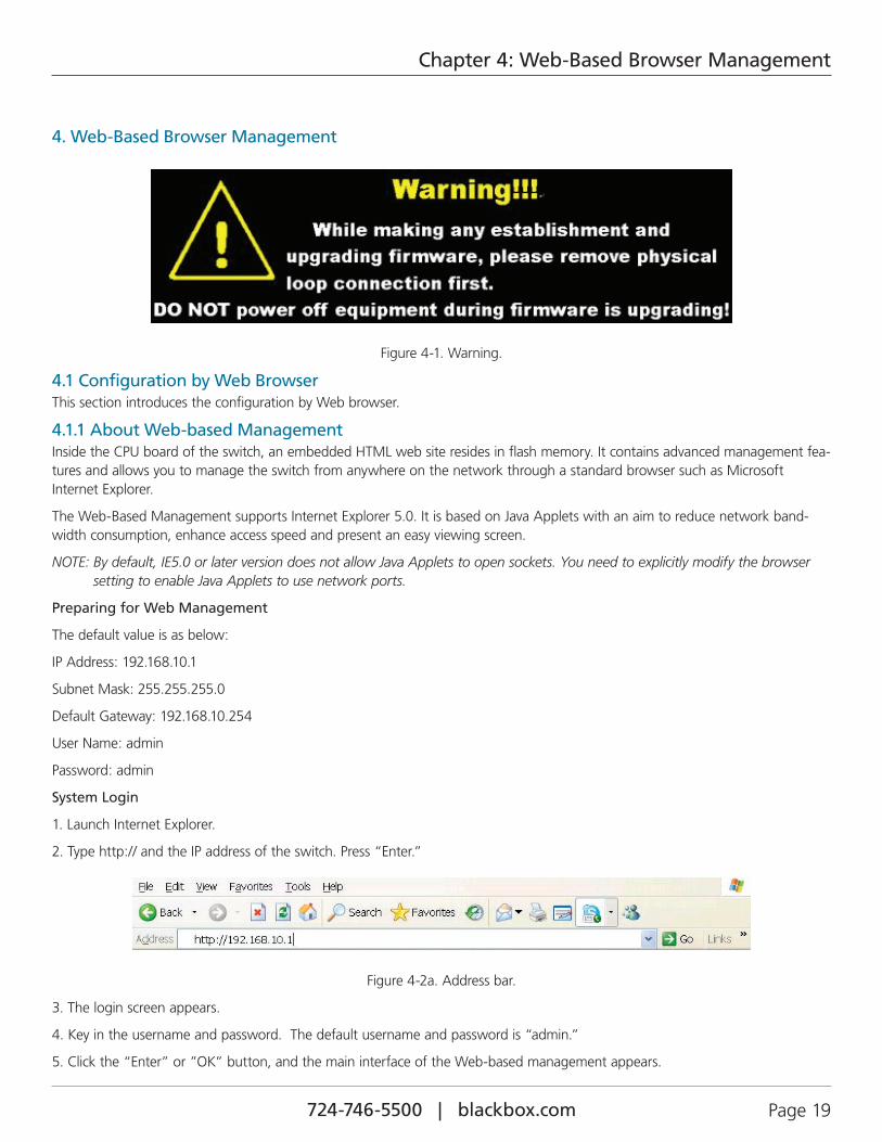
4. Web-Based Browser Management
Figure 4-1. Warning.
4.1 Configuration by Web BrowserThis section introduces the configuration by Web browser.
4.1.1 About Web-based ManagementInside the CPU board of the switch, an embedded HTML web site resides in flash memory. It contains advanced management fea-tures and allows you to manage the switch from anywhere on the network through a standard browser such as Microsoft Internet Explorer.
The Web-Based Management supports Internet Explorer 5.0. It is based on Java Applets with an aim to reduce network band-width consumption, enhance access speed and present an easy viewing screen.
NOTE: By default, IE5.0 or later version does not allow Java Applets to open sockets. You need to explicitly modify the browser setting to enable Java Applets to use network ports.
Preparing for Web Management
The default value is as below:
IP Address: 192.168.10.1
Subnet Mask: 255.255.255.0
Default Gateway: 192.168.10.254
User Name: admin
Password: admin
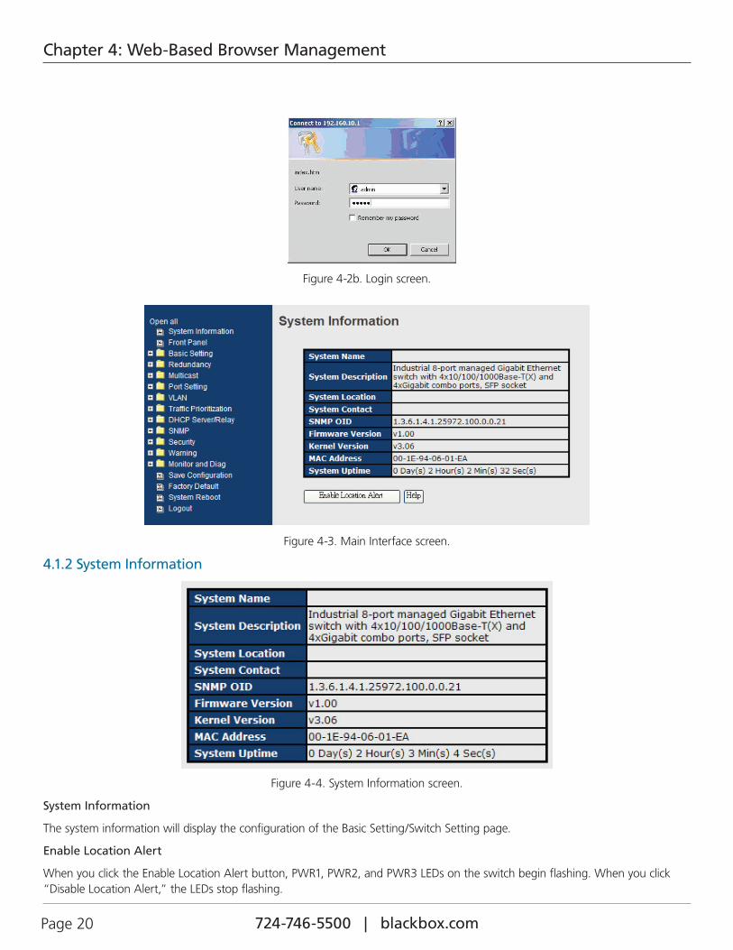
System Login
1. Launch Internet Explorer.
2. Type http:// and the IP address of the switch. Press “Enter.”
Figure 4-2a. Address bar.
3. The login screen appears.
4. Key in the username and password. The default username and password is “admin.”
5. Click the “Enter” or ”OK” button, and the main interface of the Web-based management appears.
724-746-5500 | blackbox.com Page 20
Chapter 4: Web-Based Browser Management
Figure 4-2b. Login screen.
Figure 4-3. Main Interface screen.
4.1.2 System Information
Figure 4-4. System Information screen.
System Information
The system information will display the configuration of the Basic Setting/Switch Setting page.
Enable Location Alert
When you click the Enable Location Alert button, PWR1, PWR2, and PWR3 LEDs on the switch begin flashing. When you click “Disable Location Alert,” the LEDs stop flashing.
724-746-5500 | blackbox.com Page 21
Chapter 4: Web-Based Browser Management
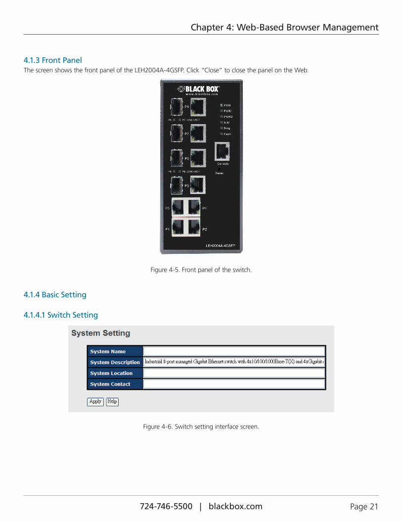
4.1.3 Front PanelThe screen shows the front panel of the LEH2004A-4GSFP. Click “Close” to close the panel on the Web.
Figure 4-5. Front panel of the switch.
4.1.4 Basic Setting
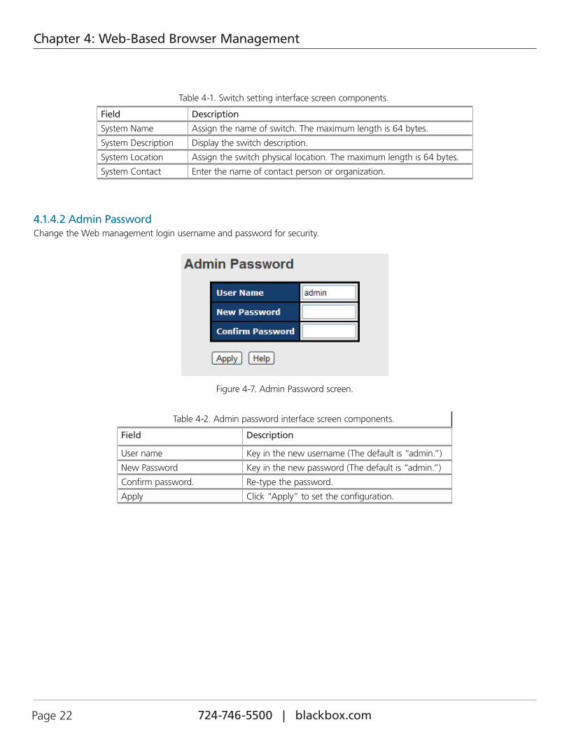
4.1.4.1 Switch Setting
Figure 4-6. Switch setting interface screen.
724-746-5500 | blackbox.com Page 22
Chapter 4: Web-Based Browser Management
Table 4-1. Switch setting interface screen components.
Field Description
System Name Assign the name of switch. The maximum length is 64 bytes.
System Description Display the switch description.
System Location Assign the switch physical location. The maximum length is 64 bytes.
System Contact Enter the name of contact person or organization.
4.1.4.2 Admin PasswordChange the Web management login username and password for security.
Figure 4-7. Admin Password screen.
Table 4-2. Admin password interface screen components.
Field Description
User name Key in the new username (The default is “admin.”)
New Password Key in the new password (The default is “admin.”)
Confirm password. Re-type the password.
Apply Click “Apply” to set the configuration.
724-746-5500 | blackbox.com Page 23
Chapter 4: Web-Based Browser Management
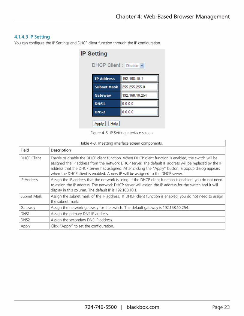
4.1.4.3 IP SettingYou can configure the IP Settings and DHCP client function through the IP configuration.
Figure 4-6. IP Setting interface screen.
Table 4-3. IP setting interface screen components.
Field Description
DHCP Client Enable or disable the DHCP client function. When DHCP client function is enabled, the switch will be assigned the IP address from the network DHCP server. The default IP address will be replaced by the IP address that the DHCP server has assigned. After clicking the “Apply” button, a popup dialog appears when the DHCP client is enabled. A new IP will be assigned to the DHCP server.
IP Address Assign the IP address that the network is using. If the DHCP client function is enabled, you do not need to assign the IP address. The network DHCP server will assign the IP address for the switch and it will display in this column. The default IP is 192.168.10.1.
Subnet Mask Assign the subnet mask of the IP address. If DHCP client function is enabled, you do not need to assign the subnet mask.
Gateway Assign the network gateway for the switch. The default gateway is 192.168.10.254.
DNS1 Assign the primary DNS IP address.
DNS2 Assign the secondary DNS IP address.
Apply Click “Apply” to set the configuration.
724-746-5500 | blackbox.com Page 24
Chapter 4: Web-Based Browser Management
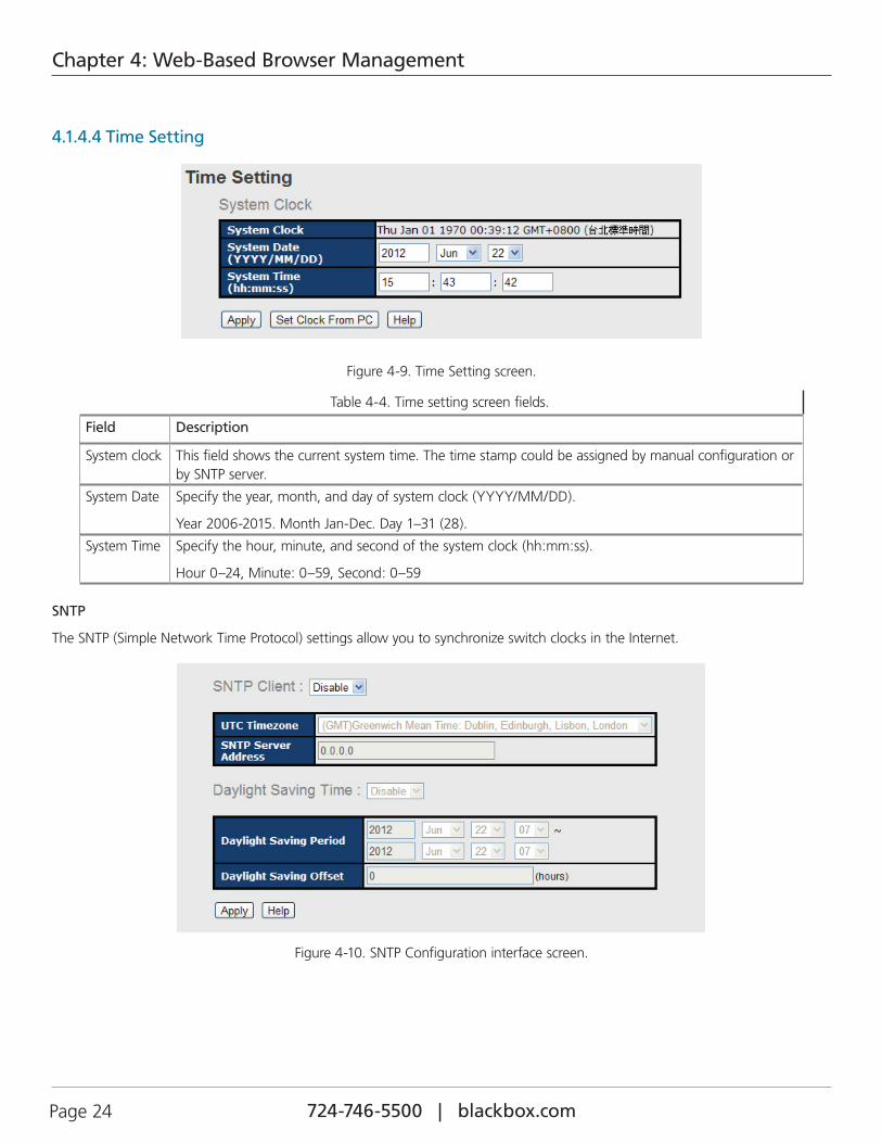
4.1.4.4 Time Setting
Figure 4-9. Time Setting screen.
Table 4-4. Time setting screen fields.
Field Description
System clock This field shows the current system time. The time stamp could be assigned by manual configuration or by SNTP server.
System Date Specify the year, month, and day of system clock (YYYY/MM/DD).
Year 2006-2015. Month Jan-Dec. Day 1–31 (28).
System Time Specify the hour, minute, and second of the system clock (hh:mm:ss).
Hour 0–24, Minute: 0–59, Second: 0–59
SNTP
The SNTP (Simple Network Time Protocol) settings allow you to synchronize switch clocks in the Internet.
Figure 4-10. SNTP Configuration interface screen.
724-746-5500 | blackbox.com Page 25
Chapter 4: Web-Based Browser Management
Table 4-5. SNTP parameters.
Field Description
SNTP Client Enable or disable SNTP function to get the time from the SNTP server.
Daylight Saving Time Enable or disable daylight saving time function. When daylight saving time is enabled, you need to configure the daylight saving time period.
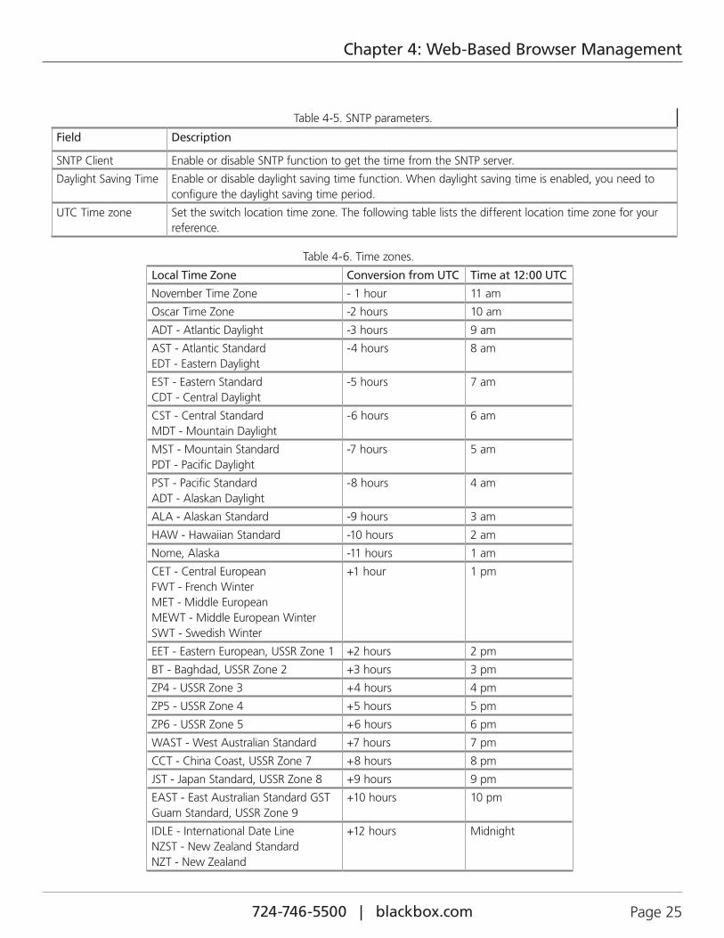
UTC Time zone Set the switch location time zone. The following table lists the different location time zone for your reference.
Table 4-6. Time zones.
Local Time Zone Conversion from UTC Time at 12:00 UTC
November Time Zone - 1 hour 11 am
Oscar Time Zone -2 hours 10 am
ADT - Atlantic Daylight -3 hours 9 am
AST - Atlantic Standard EDT - Eastern Daylight
-4 hours 8 am
EST - Eastern Standard CDT - Central Daylight
-5 hours 7 am
CST - Central Standard MDT - Mountain Daylight
-6 hours 6 am
MST - Mountain Standard PDT - Pacific Daylight
-7 hours 5 am
PST - Pacific Standard ADT - Alaskan Daylight
-8 hours 4 am
ALA - Alaskan Standard -9 hours 3 am
HAW - Hawaiian Standard -10 hours 2 am
Nome, Alaska -11 hours 1 am
CET - Central European FWT - French Winter MET - Middle European MEWT - Middle European Winter SWT - Swedish Winter
+1 hour 1 pm
EET - Eastern European, USSR Zone 1 +2 hours 2 pm
BT - Baghdad, USSR Zone 2 +3 hours 3 pm
ZP4 - USSR Zone 3 +4 hours 4 pm
ZP5 - USSR Zone 4 +5 hours 5 pm
ZP6 - USSR Zone 5 +6 hours 6 pm
WAST - West Australian Standard +7 hours 7 pm
CCT - China Coast, USSR Zone 7 +8 hours 8 pm
JST - Japan Standard, USSR Zone 8 +9 hours 9 pm
EAST - East Australian Standard GST Guam Standard, USSR Zone 9
+10 hours 10 pm
IDLE - International Date Line NZST - New Zealand Standard NZT - New Zealand
+12 hours Midnight
724-746-5500 | blackbox.com Page 26
Chapter 4: Web-Based Browser Management
Table 4-7.
Field Description
SNTP Sever IP Address Set the SNTP server IP address.
Daylight Saving Period Set up the Daylight Saving beginning time and Daylight Saving ending time. Both will be dif-ferent each year.
Daylight Saving Offset Set up the offset time.
Switch Timer Display the switch current time.
Apply Click “Apply” to set the configuration.
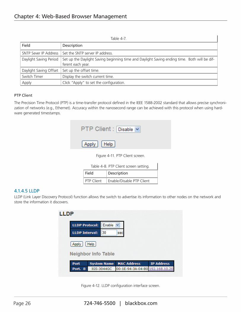
PTP Client
The Precision Time Protocol (PTP) is a time-transfer protocol defined in the IEEE 1588-2002 standard that allows precise synchroni-zation of networks (e.g., Ethernet). Accuracy within the nanosecond range can be achieved with this protocol when using hard-ware generated timestamps.
Figure 4-11. PTP Client screen.
Table 4-8. PTP Client screen setting.
Field Description
PTP Client Enable/Disable PTP Client
4.1.4.5 LLDPLLDP (Link Layer Discovery Protocol) function allows the switch to advertise its information to other nodes on the network and store the information it discovers.
Figure 4-12. LLDP configuration interface screen.
724-746-5500 | blackbox.com Page 27
Chapter 4: Web-Based Browser Management
Table 4-9. LLDP Configuration screen components.
Field Description
LLDP Protocol “Enable” or “Disable” LLDP function.
LLDP Interval The time interval that the switch waits before it resends LLDP (the default setting is 30 seconds).
Apply Click “Apply” to activate the configuration.
Help Display the help file.
Neighbor info table Can show neighbor device information.
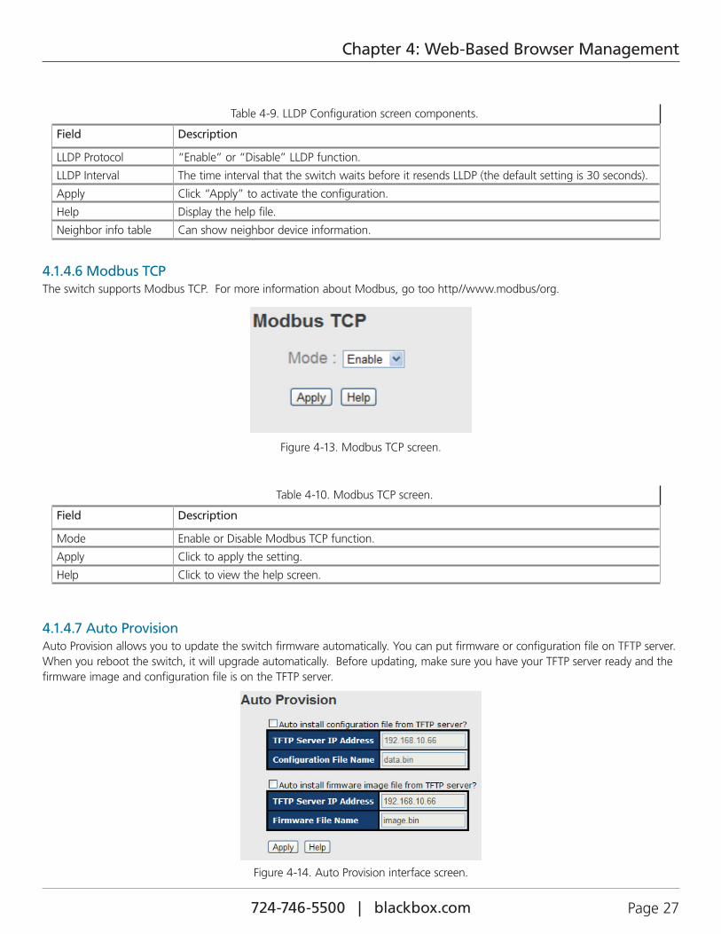
4.1.4.6 Modbus TCPThe switch supports Modbus TCP. For more information about Modbus, go too http//www.modbus/org.
Figure 4-13. Modbus TCP screen.
Table 4-10. Modbus TCP screen.
Field Description
Mode Enable or Disable Modbus TCP function.
Apply Click to apply the setting.
Help Click to view the help screen.
4.1.4.7 Auto ProvisionAuto Provision allows you to update the switch firmware automatically. You can put firmware or configuration file on TFTP server. When you reboot the switch, it will upgrade automatically. Before updating, make sure you have your TFTP server ready and the firmware image and configuration file is on the TFTP server.
Figure 4-14. Auto Provision interface screen.
724-746-5500 | blackbox.com Page 28
Chapter 4: Web-Based Browser Management
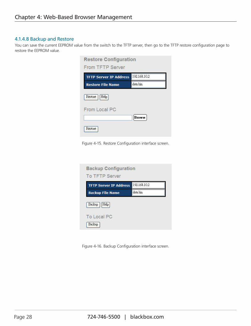
4.1.4.8 Backup and RestoreYou can save the current EEPROM value from the switch to the TFTP server, then go to the TFTP restore configuration page to restore the EEPROM value.
Figure 4-15. Restore Configuration interface screen.
Figure 4-16. Backup Configuration interface screen.
724-746-5500 | blackbox.com Page 29
Chapter 4: Web-Based Browser Management
Table 4-11. Backup and Restore interface screen components.
Field Description
TFTP Server IP Address Fill in the TFTP server IP.
Restore File Name Fill in the file name.
Restore Click “restore” to restore the configurations.
From Local PC Select restore without needing an TFTP server.
Restore File Name Fill in the file name.
Backup button Go back to the previous setting.
Help Click on this button for help.
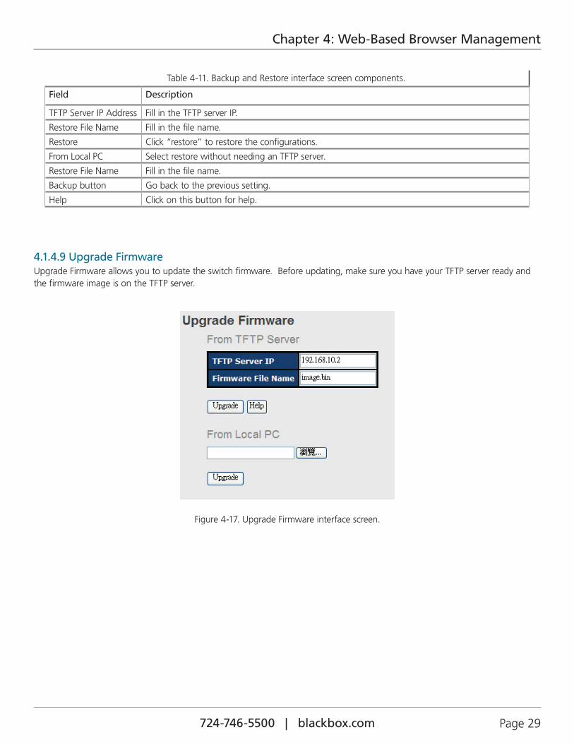
4.1.4.9 Upgrade FirmwareUpgrade Firmware allows you to update the switch firmware. Before updating, make sure you have your TFTP server ready and the firmware image is on the TFTP server.
Figure 4-17. Upgrade Firmware interface screen.
724-746-5500 | blackbox.com Page 30
Chapter 4: Web-Based Browser Management
4.1.5 Redundancy
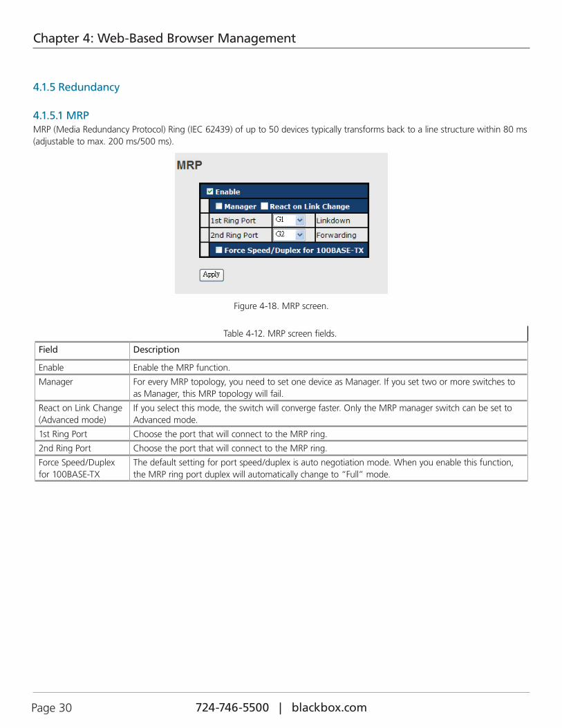
4.1.5.1 MRPMRP (Media Redundancy Protocol) Ring (IEC 62439) of up to 50 devices typically transforms back to a line structure within 80 ms (adjustable to max. 200 ms/500 ms).
Figure 4-18. MRP screen.
Table 4-12. MRP screen fields.
Field Description
Enable Enable the MRP function.
Manager For every MRP topology, you need to set one device as Manager. If you set two or more switches to as Manager, this MRP topology will fail.
React on Link Change (Advanced mode)
If you select this mode, the switch will converge faster. Only the MRP manager switch can be set to Advanced mode.
1st Ring Port Choose the port that will connect to the MRP ring.
2nd Ring Port Choose the port that will connect to the MRP ring.
Force Speed/Duplex for 100BASE-TX
The default setting for port speed/duplex is auto negotiation mode. When you enable this function, the MRP ring port duplex will automatically change to “Full” mode.

724-746-5500 | blackbox.com Page 31
Chapter 4: Web-Based Browser Management
4.1.5.2 B-RingB-Ring recovery time is less than 20 ms. It can reduce unexpected damage caused by network topology changes. B-Ring Supports a 3-Ring topology: B-Ring, Coupling Ring, and Dual Homing.
Figure 4-19. B-Ring interface screen.
Table 4-13. B-Ring interface screen components.
Field Description
Redundant Ring Mark to enable B-Ring.
Enable Ring Master There should be one and only one Ring Master in a B-Ring. However, if there are two or more switches that set Ring Master to enable, the switch with the lowest MAC address will be the actual Ring Master and others will be Backup Masters.
1st Ring Port The primary port when this switch is Ring Master.
2nd Ring Port The backup port when this switch is Ring Master.
Enable Coupling Ring Mark to enable Coupling Ring. Coupling Ring can be used to divide a big ring into two smaller rings to avoid affecting all switches when a network topology changes. It is a good application for connecting two Rings.
Coupling Port Link to Coupling Port of the switch in another ring. Coupling Ring needs four switch to build an active and a backup link.
Set a port as coupling port. The coupled four ports of four switches will run in active/backup mode.
Control Port Link to the control port of the switch in the same ring. This port is used to transmit control signals.
Enable Dual Homing Mark to enable Dual Homing. When you select Dual Homing mode, the Ring will be connected to normal switches through two RSTP links (ex: backbone Switch). The two links work in active/back-up mode, and connect each Ring to the normal switches in RSTP mode.
Apply Click “Apply” to set the configuration.
NOTE: We do not recommend that you set one switch as a Ring Master and a Coupling Ring at the same time because of a heavy load.
724-746-5500 | blackbox.com Page 32
Chapter 4: Web-Based Browser Management
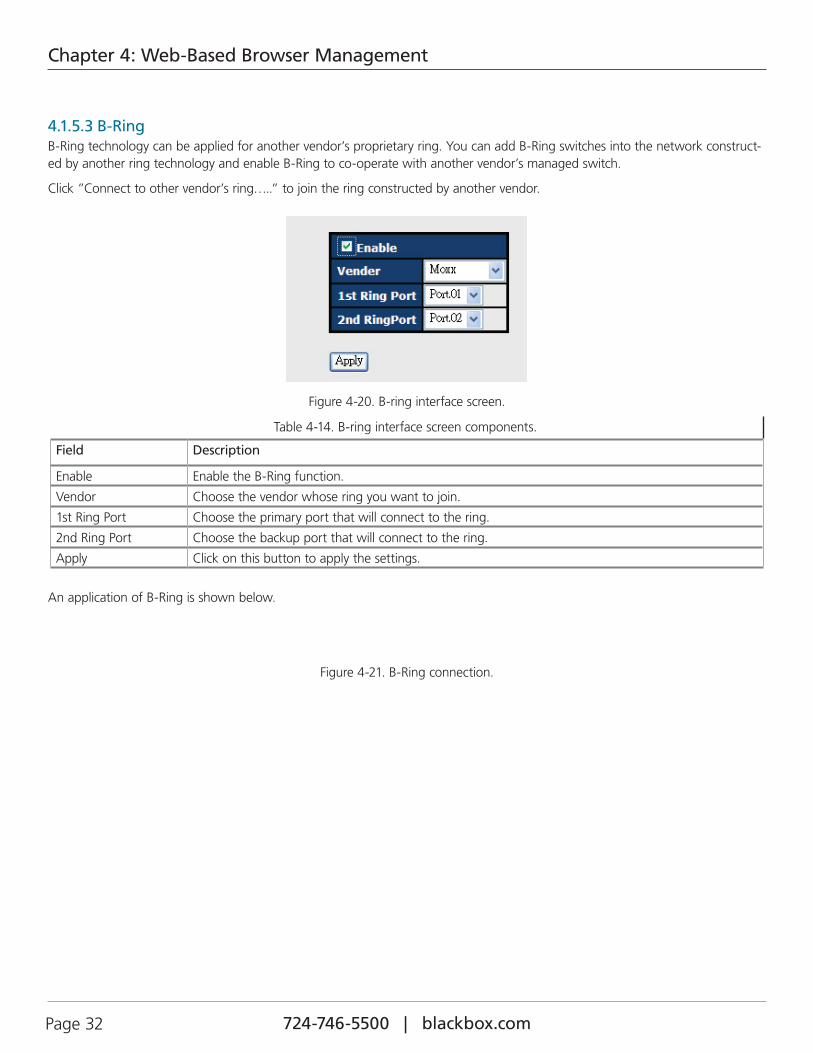
4.1.5.3 B-RingB-Ring technology can be applied for another vendor’s proprietary ring. You can add B-Ring switches into the network construct-ed by another ring technology and enable B-Ring to co-operate with another vendor’s managed switch.
Click ”Connect to other vendor’s ring…..” to join the ring constructed by another vendor.
Figure 4-20. B-ring interface screen.
Table 4-14. B-ring interface screen components.
Field Description
Enable Enable the B-Ring function.
Vendor Choose the vendor whose ring you want to join.
1st Ring Port Choose the primary port that will connect to the ring.
2nd Ring Port Choose the backup port that will connect to the ring.
Apply Click on this button to apply the settings.
An application of B-Ring is shown below.
Figure 4-21. B-Ring connection.
724-746-5500 | blackbox.com Page 33
Chapter 4: Web-Based Browser Management
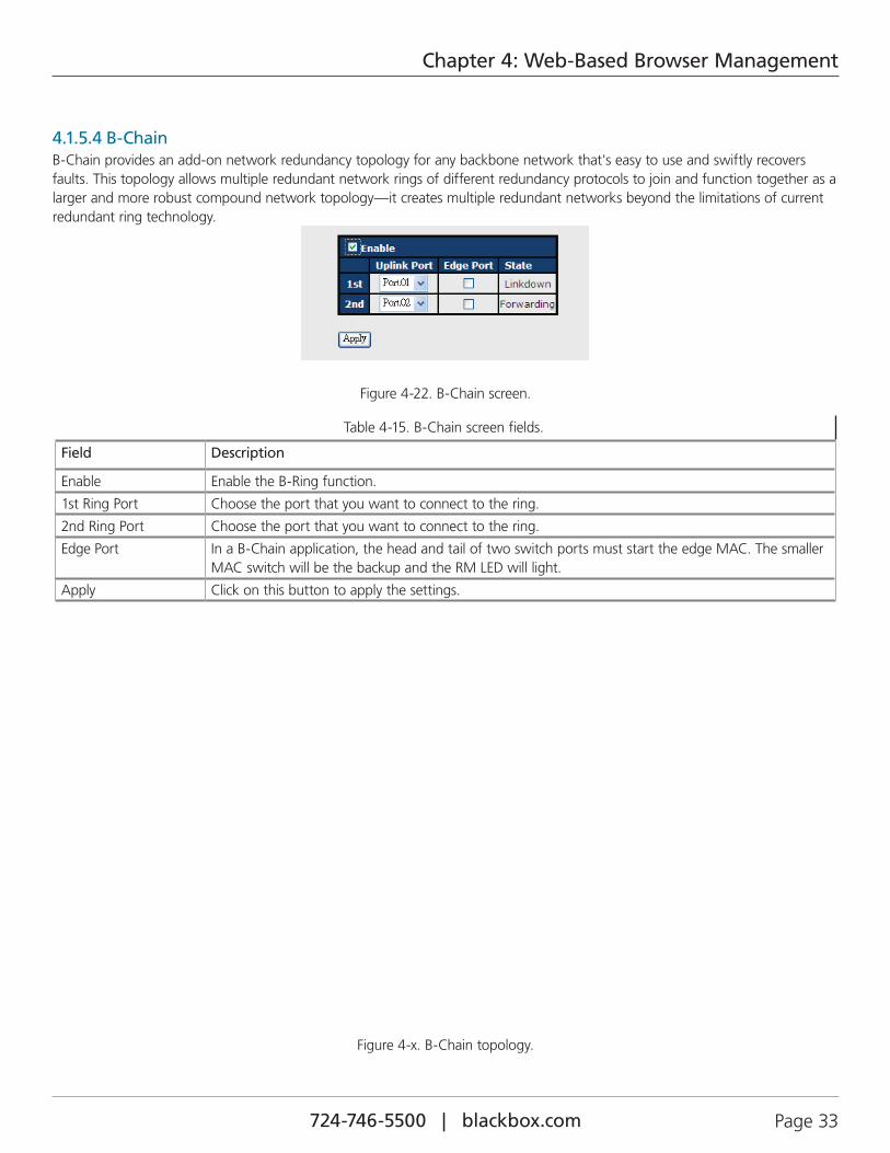
4.1.5.4 B-ChainB-Chain provides an add-on network redundancy topology for any backbone network that's easy to use and swiftly recovers faults. This topology allows multiple redundant network rings of different redundancy protocols to join and function together as a larger and more robust compound network topology—it creates multiple redundant networks beyond the limitations of current redundant ring technology.
Figure 4-22. B-Chain screen.
Table 4-15. B-Chain screen fields.
Field Description
Enable Enable the B-Ring function.
1st Ring Port Choose the port that you want to connect to the ring.
2nd Ring Port Choose the port that you want to connect to the ring.
Edge Port In a B-Chain application, the head and tail of two switch ports must start the edge MAC. The smaller MAC switch will be the backup and the RM LED will light.
Apply Click on this button to apply the settings.
Figure 4-x. B-Chain topology.
724-746-5500 | blackbox.com Page 34
Chapter 4: Web-Based Browser Management
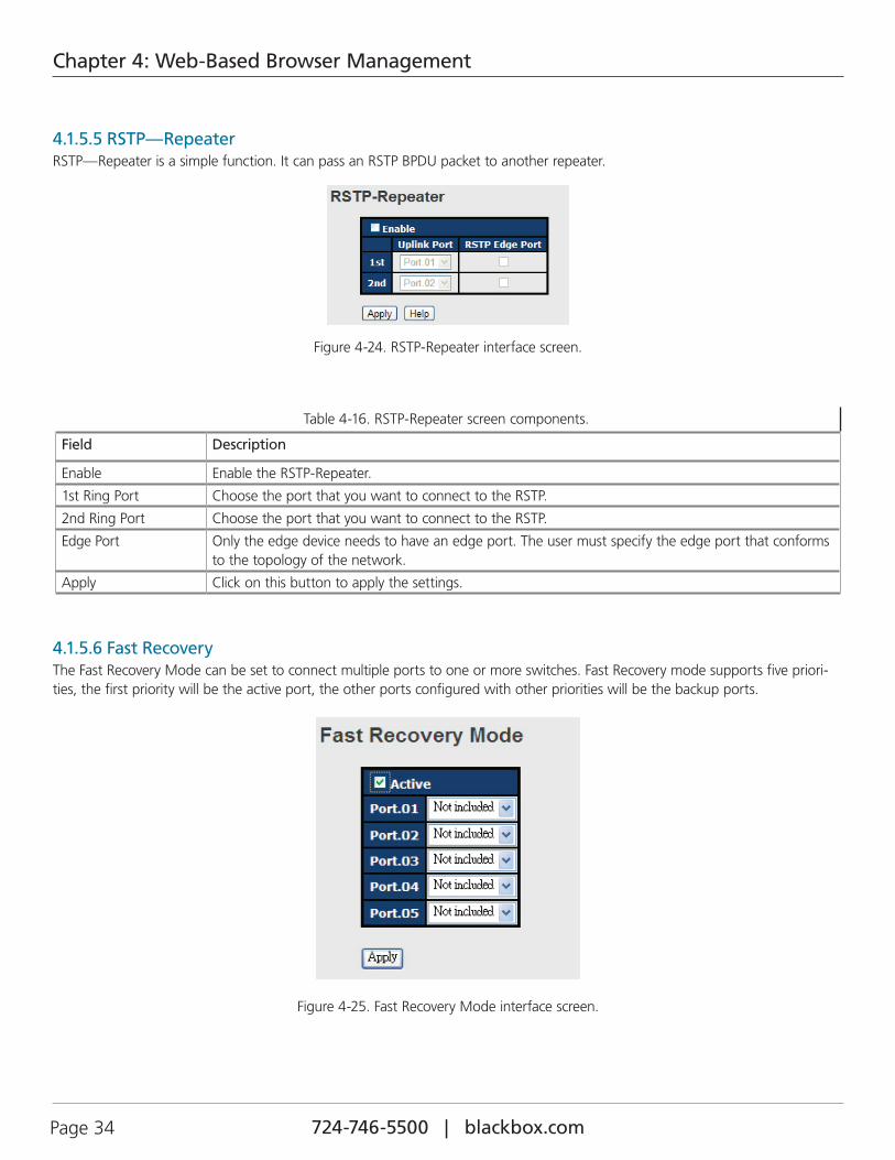
4.1.5.5 RSTP—RepeaterRSTP—Repeater is a simple function. It can pass an RSTP BPDU packet to another repeater.
Figure 4-24. RSTP-Repeater interface screen.
Table 4-16. RSTP-Repeater screen components.
Field Description
Enable Enable the RSTP-Repeater.
1st Ring Port Choose the port that you want to connect to the RSTP.
2nd Ring Port Choose the port that you want to connect to the RSTP.
Edge Port Only the edge device needs to have an edge port. The user must specify the edge port that conforms to the topology of the network.
Apply Click on this button to apply the settings.
4.1.5.6 Fast RecoveryThe Fast Recovery Mode can be set to connect multiple ports to one or more switches. Fast Recovery mode supports five priori-ties, the first priority will be the active port, the other ports configured with other priorities will be the backup ports.
Figure 4-25. Fast Recovery Mode interface screen.
724-746-5500 | blackbox.com Page 35
Chapter 4: Web-Based Browser Management
Table 4-17. Fast Recovery Mode interface screen fields.
Field Description
Active Activate the Fast Recovery mode.
Port Port can be configured as 5 priorities. Only the port configured with first priority will be the active port.
Apply Click on this button to apply the settings.
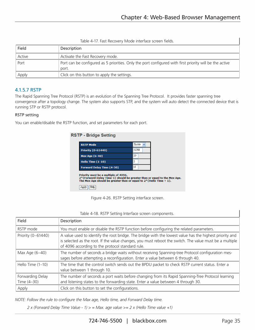
4.1.5.7 RSTPThe Rapid Spanning Tree Protocol (RSTP) is an evolution of the Spanning Tree Protocol. It provides faster spanning tree convergence after a topology change. The system also supports STP, and the system will auto detect the connected device that is running STP or RSTP protocol.
RSTP setting
You can enable/disable the RSTP function, and set parameters for each port.
Figure 4-26. RSTP Setting interface screen.
Table 4-18. RSTP Setting Interface screen components.
Field Description
RSTP mode You must enable or disable the RSTP function before configuring the related parameters.
Priority (0–61440) A value used to identify the root bridge. The bridge with the lowest value has the highest priority and is selected as the root. If the value changes, you must reboot the switch. The value must be a multiple of 4096 according to the protocol standard rule.
Max Age (6–40) The number of seconds a bridge waits without receiving Spanning-tree Protocol configuration mes-sages before attempting a reconfiguration. Enter a value between 6 through 40.
Hello Time (1–10) The time that the control switch sends out the BPDU packet to check RSTP current status. Enter a value between 1 through 10.
Forwarding Delay Time (4–30)
The number of seconds a port waits before changing from its Rapid Spanning-Tree Protocol learning and listening states to the forwarding state. Enter a value between 4 through 30.
Apply Click on this button to set the configurations.
NOTE: Follow the rule to configure the Max age, Hello time, and Forward Delay time.
2 x (Forward Delay Time Value - 1) > = Max. age value >= 2 x (Hello Time value +1)
724-746-5500 | blackbox.com Page 36
Chapter 4: Web-Based Browser Management
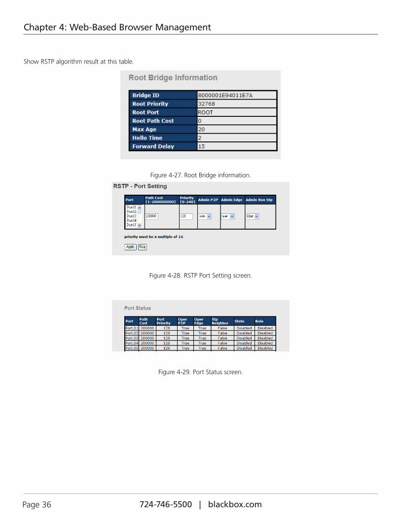
Show RSTP algorithm result at this table.
Figure 4-27. Root Bridge information.
Figure 4-28. RSTP Port Setting screen.
Figure 4-29. Port Status screen.
724-746-5500 | blackbox.com Page 37
Chapter 4: Web-Based Browser Management
Table 4-19. Port Status screen options.
Field Description
Path Cost (1–200000000)
The cost of the path to the other bridge from this transmitting bridge at the specified port. Enter a number 1 through 200000000.
Priority (0–240) Decide which port should be blocked by priority in LAN. Enter a number 0 through 240. The value of priority must be the multiple of 16.
Admin P2P Some of the rapid state transactions that are possible within RSTP depend upon whether the port concerned can only be connected to exactly one other bridge (i.e., It is served by a point-to-point LAN segment), or it can be connected to two or more bridges (i.e., It is served by a shared medium LAN segment). This function allows the P2P status of the link to be manipulated administratively. True means P2P enabling. False means P2P disabling.
Admin Edge This is the port directly connected to end stations, and it cannot create a bridging loop in the net-work. To configure the port as an edge port, set the port to “True.”
Admin Non STP Whether or not the port includes the STP mathematical calculation. True is not including the STP mathematical calculation. False is including the STP mathematic calculation.
Apply Click “Apply” to set the configuration.
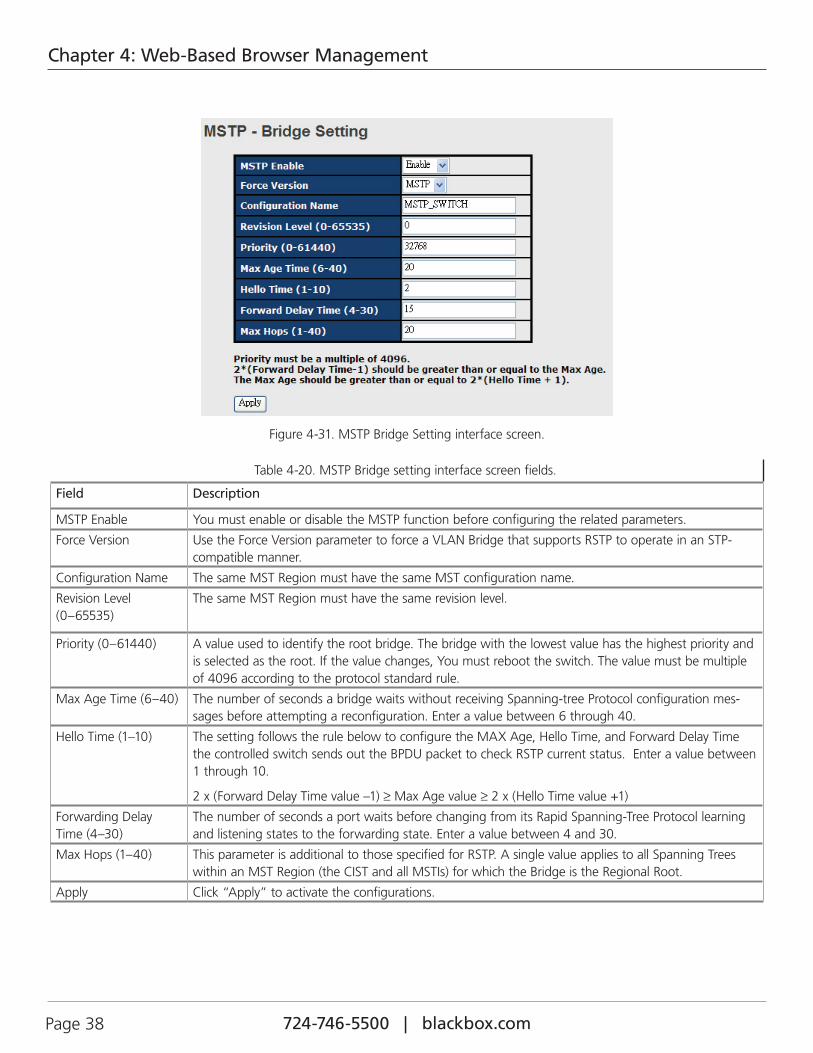
4.1.5.8 MSTPMultiple Spanning Tree Protocol (MSTP) is a standard protocol base on IEEE 802.1s. The function is that several VLANs can be mapping to a reduced number of spanning tree instances because most networks do not need more than a few logical topolo-gies. It supports load balancing scheme and the CPU is sparer than PVST (Cisco proprietary technology).
724-746-5500 | blackbox.com Page 38
Chapter 4: Web-Based Browser Management
Figure 4-31. MSTP Bridge Setting interface screen.
Table 4-20. MSTP Bridge setting interface screen fields.
Field Description
MSTP Enable You must enable or disable the MSTP function before configuring the related parameters.
Force Version Use the Force Version parameter to force a VLAN Bridge that supports RSTP to operate in an STP-compatible manner.
Configuration Name The same MST Region must have the same MST configuration name.
Revision Level (0–65535)
The same MST Region must have the same revision level.
Priority (0–61440) A value used to identify the root bridge. The bridge with the lowest value has the highest priority and is selected as the root. If the value changes, You must reboot the switch. The value must be multiple of 4096 according to the protocol standard rule.
Max Age Time (6–40) The number of seconds a bridge waits without receiving Spanning-tree Protocol configuration mes-sages before attempting a reconfiguration. Enter a value between 6 through 40.
Hello Time (1–10) The setting follows the rule below to configure the MAX Age, Hello Time, and Forward Delay Time the controlled switch sends out the BPDU packet to check RSTP current status. Enter a value between 1 through 10.
2 x (Forward Delay Time value –1) ≥ Max Age value ≥ 2 x (Hello Time value +1)
Forwarding Delay Time (4–30)
The number of seconds a port waits before changing from its Rapid Spanning-Tree Protocol learning and listening states to the forwarding state. Enter a value between 4 and 30.
Max Hops (1–40) This parameter is additional to those specified for RSTP. A single value applies to all Spanning Trees within an MST Region (the CIST and all MSTIs) for which the Bridge is the Regional Root.
Apply Click “Apply” to activate the configurations.
724-746-5500 | blackbox.com Page 39
Chapter 4: Web-Based Browser Management
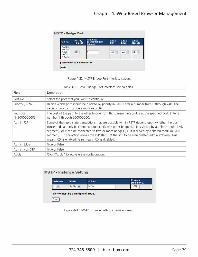
Figure 4-32. MSTP Bridge Port interface screen.
Table 4-21. MSTP Bridge Port interface screen fields.
Field Description
Port No. Select the port that you want to configure.
Priority (0–240) Decide which port should be blocked by priority in LAN. Enter a number from 0 through 240. The value of priority must be a multiple of 16.
Path Cost (1–200000000)
The cost of the path to the other bridge from this transmitting bridge at the specified port. Enter a number 1 through 200000000.
Admin P2P Some of the rapid state transactions that are possible within RSTP depend upon whether the port concerned can only be connected to exactly one other bridge (i.e. It is served by a point-to-point LAN segment), or it can be connected to two or more bridges (i.e. It is served by a shared medium LAN segment). This function allows the P2P status of the link to be manipulated administratively. True means P2P is enabled. False means P2P is disabled.
Admin Edge True or False.
Admin Non STP True or False.
Apply Click “Apply” to activate the configuration.
Figure 4-33. MSTP Instance Setting interface screen.
724-746-5500 | blackbox.com Page 40
Chapter 4: Web-Based Browser Management
Table 4-22. MSTP Instance Setting interface screen fields.
Field Description
Instance Set the instance from 1 to 15.
State Enable or disable the instance.
VLANs Set which VLAN will belong to which instance.
Proprietary (0–61440) A value used to identify the root bridge. The bridge with the lowest value has the highest priority and is selected as the root. If the value changes, you must reboot the switch. he value must be a multiple of 4096 according to the protocol standard rule.
Apply Click “Apply” to activate the configuration.
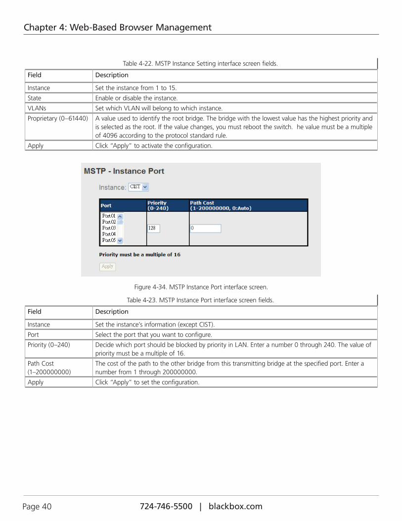
Figure 4-34. MSTP Instance Port interface screen.
Table 4-23. MSTP Instance Port interface screen fields.
Field Description
Instance Set the instance’s information (except CIST).
Port Select the port that you want to configure.
Priority (0–240) Decide which port should be blocked by priority in LAN. Enter a number 0 through 240. The value of priority must be a multiple of 16.
Path Cost (1–200000000)
The cost of the path to the other bridge from this transmitting bridge at the specified port. Enter a number from 1 through 200000000.
Apply Click “Apply” to set the configuration.
724-746-5500 | blackbox.com Page 41
Chapter 4: Web-Based Browser Management
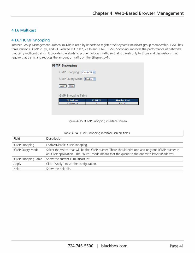
4.1.6 Multicast
4.1.6.1 IGMP SnoopingInternet Group Management Protocol (IGMP) is used by IP hosts to register their dynamic multicast group membership. IGMP has three versions: IGMP v1, v2, and v3. Refer to RFC 1112, 2236 and 3376. IGMP Snooping improves the performance of networks that carry multicast traffic. It provides the ability to prune multicast traffic so that it travels only to those end destinations that require that traffic and reduces the amount of traffic on the Ethernet LAN.
Figure 4-35. IGMP Snooping interface screen.
Table 4-24. IGMP Snooping interface screen fields.
Field Description
IGMP Snooping Enable/Disable IGMP snooping.
IGMP Query Mode Select the switch that will be the IGMP querier. There should exist one and only one IGMP querier in an IGMP application. The "Auto" mode means that the querier is the one with lower IP address.
IGMP Snooping Table Show the current IP multicast list.
Apply Click “Apply” to set the configuration.
Help Show the help file.
724-746-5500 | blackbox.com Page 42
Chapter 4: Web-Based Browser Management
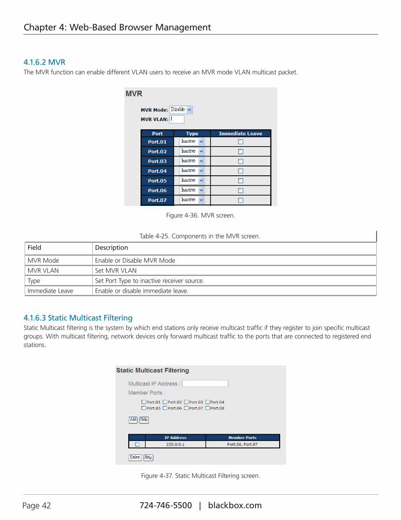
4.1.6.2 MVRThe MVR function can enable different VLAN users to receive an MVR mode VLAN multicast packet.
Figure 4-36. MVR screen.
Table 4-25. Components in the MVR screen.
Field Description
MVR Mode Enable or Disable MVR Mode
MVR VLAN Set MVR VLAN
Type Set Port Type to inactive receiver source.
Immediate Leave Enable or disable immediate leave.
4.1.6.3 Static Multicast FilteringStatic Multicast filtering is the system by which end stations only receive multicast traffic if they register to join specific multicast groups. With multicast filtering, network devices only forward multicast traffic to the ports that are connected to registered end stations.
Figure 4-37. Static Multicast Filtering screen.
724-746-5500 | blackbox.com Page 43
Chapter 4: Web-Based Browser Management
Table 4-26. Static Multicast Filtering screen options.
Field Description
IP Address Assign a multicast group IP address in the range of 224.0.0.0—239.255.255.255
Member Ports Tick the check box beside the port number to include them as the member ports in the specific multicast group IP address.
Add Show current IP multicast list.
Delete Delete an entry from the table.
Help Show the help file.
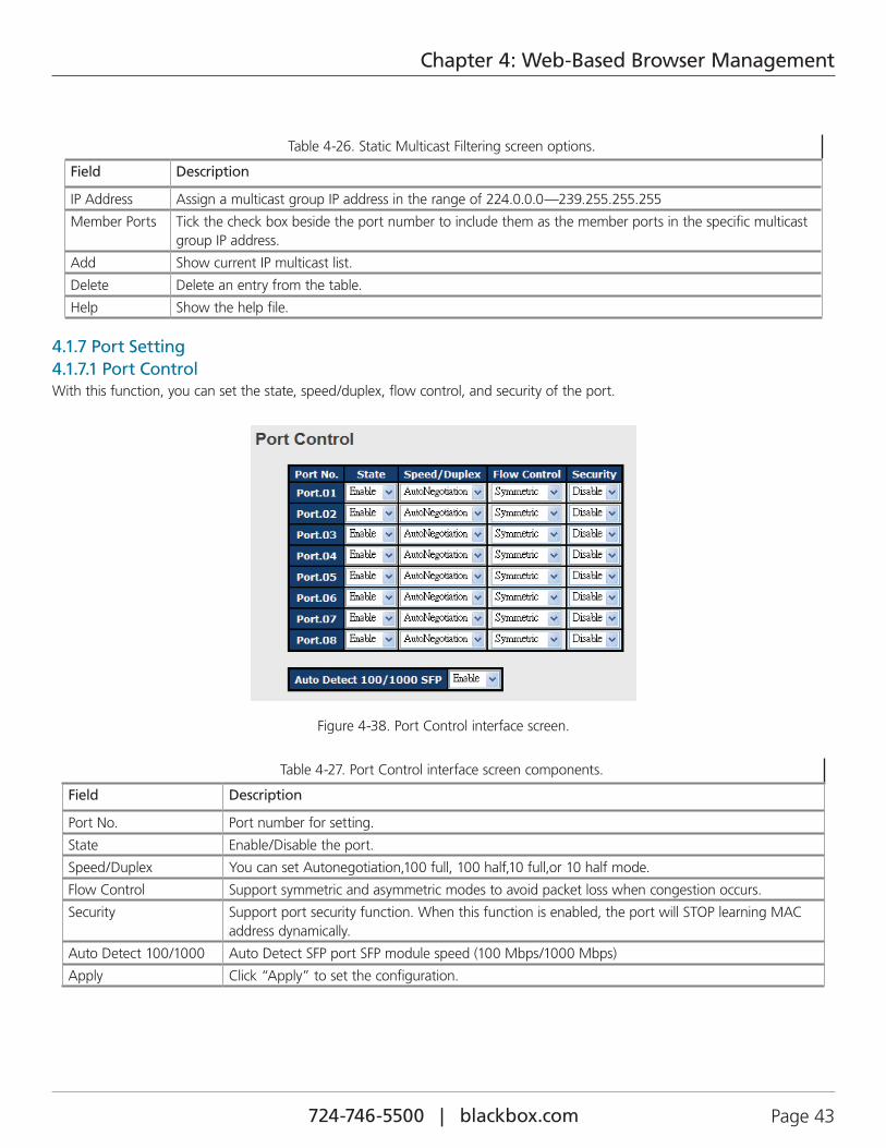
4.1.7 Port Setting4.1.7.1 Port ControlWith this function, you can set the state, speed/duplex, flow control, and security of the port.
Figure 4-38. Port Control interface screen.
Table 4-27. Port Control interface screen components.
Field Description
Port No. Port number for setting.
State Enable/Disable the port.
Speed/Duplex You can set Autonegotiation,100 full, 100 half,10 full,or 10 half mode.
Flow Control Support symmetric and asymmetric modes to avoid packet loss when congestion occurs.
Security Support port security function. When this function is enabled, the port will STOP learning MAC address dynamically.
Auto Detect 100/1000 Auto Detect SFP port SFP module speed (100 Mbps/1000 Mbps)
Apply Click “Apply” to set the configuration.
724-746-5500 | blackbox.com Page 44
Chapter 4: Web-Based Browser Management
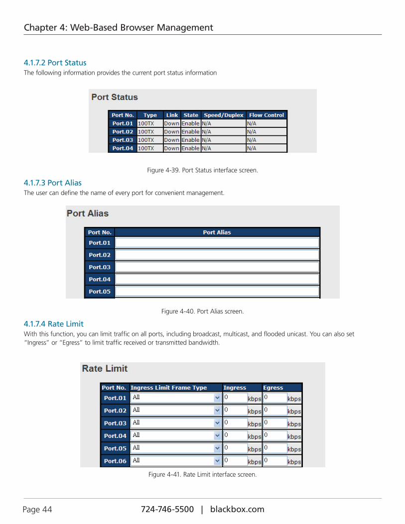
4.1.7.2 Port StatusThe following information provides the current port status information
Figure 4-39. Port Status interface screen.
4.1.7.3 Port AliasThe user can define the name of every port for convenient management.
Figure 4-40. Port Alias screen.
4.1.7.4 Rate LimitWith this function, you can limit traffic on all ports, including broadcast, multicast, and flooded unicast. You can also set “Ingress” or “Egress” to limit traffic received or transmitted bandwidth.
Figure 4-41. Rate Limit interface screen.
724-746-5500 | blackbox.com Page 45
Chapter 4: Web-Based Browser Management
Table 4-28. Rate Limit interface screen components.
Field Description
Ingress Limit Frame Type
You can set “all,” “Broadcast only,” ”Broadcast/Multicast,” or ”Broadcast/Multicast/Flooded Unicast” mode.
Ingress The switch port received traffic.
Egress The switch port transmitted traffic.
Immediate Leave Enable or disable immediate leave.
Apply Click “Apply” to set the configuration.
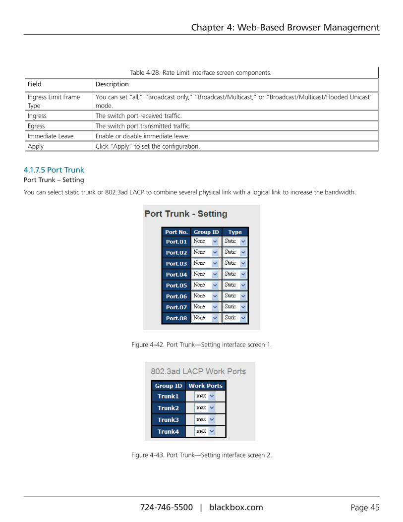
4.1.7.5 Port TrunkPort Trunk – Setting
You can select static trunk or 802.3ad LACP to combine several physical link with a logical link to increase the bandwidth.
Figure 4-42. Port Trunk—Setting interface screen 1.
Figure 4-43. Port Trunk—Setting interface screen 2.
724-746-5500 | blackbox.com Page 46
Chapter 4: Web-Based Browser Management
Table 4-29. Port Trunk —Setting Interface screen options.
Field Description
Group ID Select a port to join a trunk group.
Type Support static trunk and 802.3ad LACP.
Work Port Select the number of active ports in dynamic group (LACP). The default value of work ports is the maximum number of the group. If the number is not the maximum number of ports, the other inactive ports in dynamic group will be suspended (no traffic). Once the active port is broken, the suspended port will be active automatically.
Apply Click “Apply” to set the configuration.
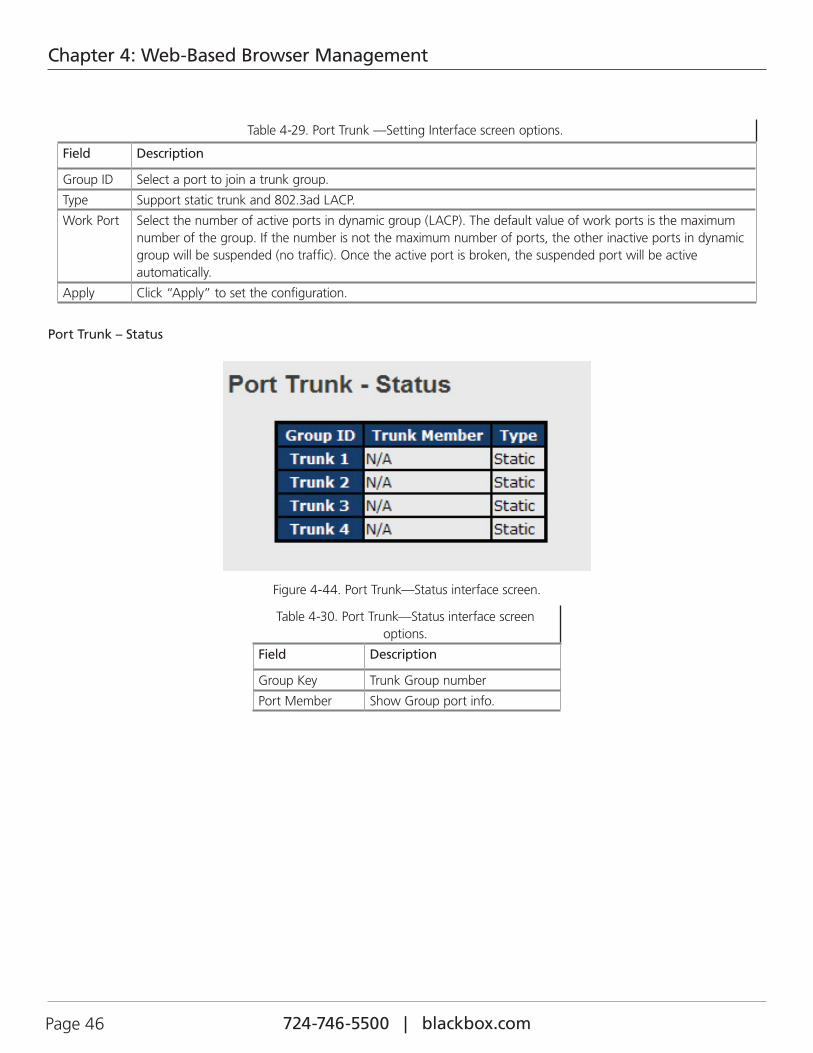
Port Trunk – Status
Figure 4-44. Port Trunk—Status interface screen.
Table 4-30. Port Trunk—Status interface screen options.
Field Description
Group Key Trunk Group number
Port Member Show Group port info.
724-746-5500 | blackbox.com Page 47
Chapter 4: Web-Based Browser Management
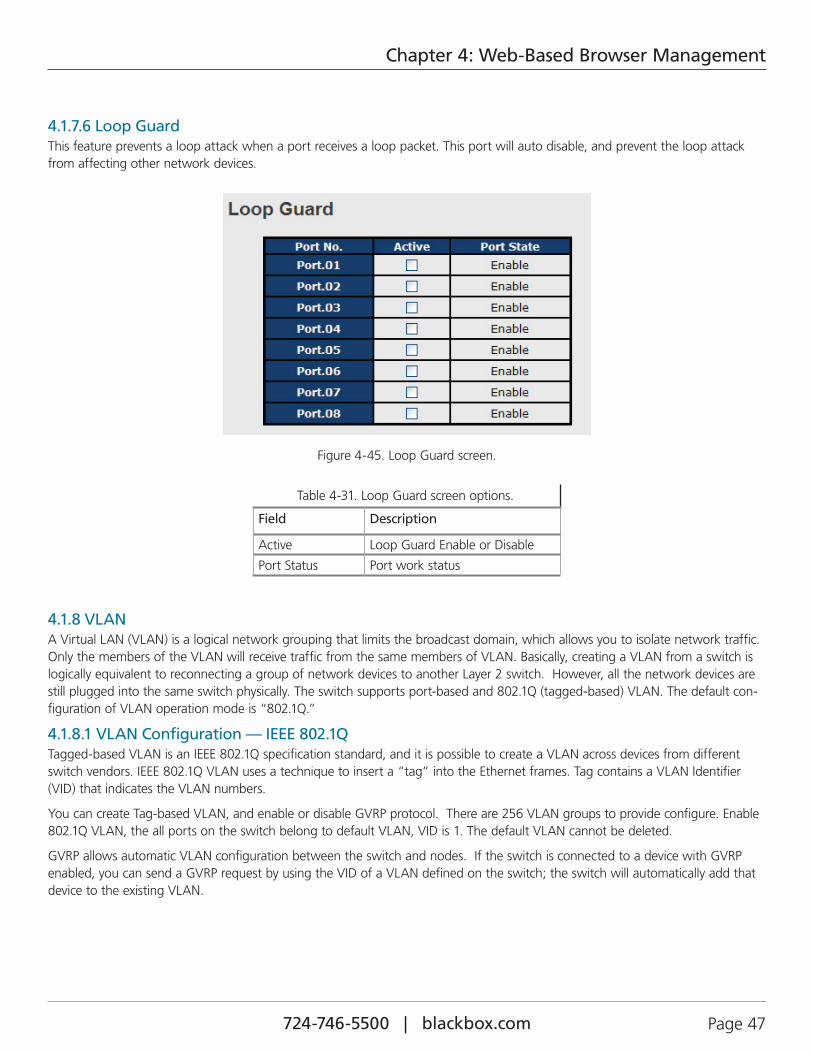
4.1.7.6 Loop GuardThis feature prevents a loop attack when a port receives a loop packet. This port will auto disable, and prevent the loop attack from affecting other network devices.
Figure 4-45. Loop Guard screen.
Table 4-31. Loop Guard screen options.
Field Description
Active Loop Guard Enable or Disable
Port Status Port work status
4.1.8 VLANA Virtual LAN (VLAN) is a logical network grouping that limits the broadcast domain, which allows you to isolate network traffic. Only the members of the VLAN will receive traffic from the same members of VLAN. Basically, creating a VLAN from a switch is logically equivalent to reconnecting a group of network devices to another Layer 2 switch. However, all the network devices are still plugged into the same switch physically. The switch supports port-based and 802.1Q (tagged-based) VLAN. The default con-figuration of VLAN operation mode is “802.1Q.”
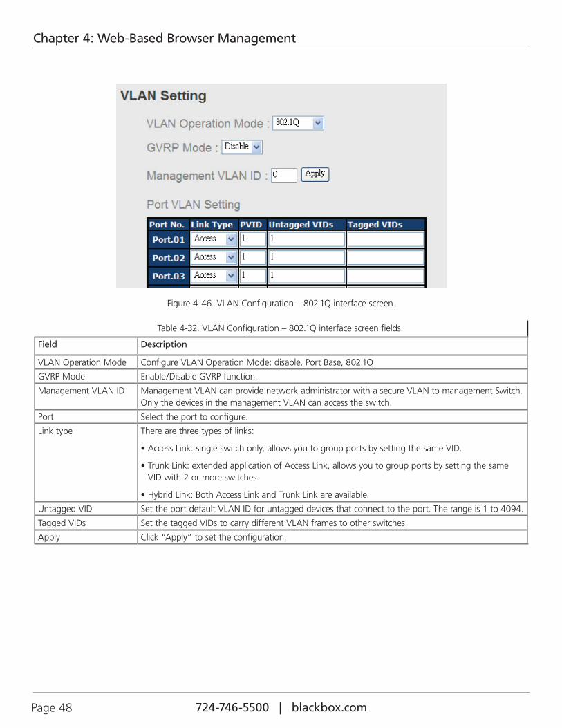
4.1.8.1 VLAN Configuration — IEEE 802.1QTagged-based VLAN is an IEEE 802.1Q specification standard, and it is possible to create a VLAN across devices from different switch vendors. IEEE 802.1Q VLAN uses a technique to insert a “tag” into the Ethernet frames. Tag contains a VLAN Identifier (VID) that indicates the VLAN numbers.
You can create Tag-based VLAN, and enable or disable GVRP protocol. There are 256 VLAN groups to provide configure. Enable 802.1Q VLAN, the all ports on the switch belong to default VLAN, VID is 1. The default VLAN cannot be deleted.
GVRP allows automatic VLAN configuration between the switch and nodes. If the switch is connected to a device with GVRP enabled, you can send a GVRP request by using the VID of a VLAN defined on the switch; the switch will automatically add that device to the existing VLAN.
724-746-5500 | blackbox.com Page 48
Chapter 4: Web-Based Browser Management
Figure 4-46. VLAN Configuration – 802.1Q interface screen.
Table 4-32. VLAN Configuration – 802.1Q interface screen fields.
Field Description
VLAN Operation Mode Configure VLAN Operation Mode: disable, Port Base, 802.1Q
GVRP Mode Enable/Disable GVRP function.
Management VLAN ID Management VLAN can provide network administrator with a secure VLAN to management Switch. Only the devices in the management VLAN can access the switch.
Port Select the port to configure.
Link type There are three types of links:
• Access Link: single switch only, allows you to group ports by setting the same VID.
• Trunk Link: extended application of Access Link, allows you to group ports by setting the same VID with 2 or more switches.
• Hybrid Link: Both Access Link and Trunk Link are available.
Untagged VID Set the port default VLAN ID for untagged devices that connect to the port. The range is 1 to 4094.
Tagged VIDs Set the tagged VIDs to carry different VLAN frames to other switches.
Apply Click “Apply” to set the configuration.
724-746-5500 | blackbox.com Page 49
Chapter 4: Web-Based Browser Management
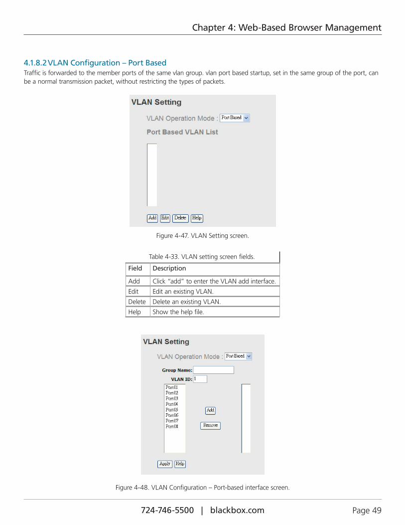
4.1.8.2 VLAN Configuration – Port BasedTraffic is forwarded to the member ports of the same vlan group. vlan port based startup, set in the same group of the port, can be a normal transmission packet, without restricting the types of packets.
Figure 4-47. VLAN Setting screen.
Table 4-33. VLAN setting screen fields.
Field Description
Add Click “add” to enter the VLAN add interface.
Edit Edit an existing VLAN.
Delete Delete an existing VLAN.
Help Show the help file.
Figure 4-48. VLAN Configuration – Port-based interface screen.
724-746-5500 | blackbox.com Page 50
Chapter 4: Web-Based Browser Management
Table 4-34. VLAN Configuration — Port-based interface screen components.
Field Description
Group Name VLAN name.
VLAN ID Specify the VLAN ID.
Add Select a port to join the VLAN group.
Remove Remove port from the VLAN group.
Apply Click “Apply” to set the configuration.
Help Show the help file.
4.1.9 Traffic PrioritizationTraffic Prioritization includes 3 modes: port base, 802.1p/COS, and TOS/DSCP. By traffic prioritization function, you can classify the traffic into four classes for differential network application. LEH2004A-4GSFP support 4 priority queues.
4.1.9.1 QoS policy
Figure 4-49. Traffic Prioritization interface screen.
Table 4-35. Traffic Prioritization interface screen fields.
Field Description
QOS Mode • Port-based: the output priority is determined by the ingress port.
• COS only: the output priority is determined by COS only.
• TOS only: the output priority is determined by TOS only.
• COS first: the output priority is determined by COS and TOS, but COS first.
• TOS first: the output priority is determined by COS and TOS, but TOS first.
QOS policy • Using the 8,4,2,1 weight fair queue scheme: the output queues will follow 8:4:2:1 ratio to transmit packets from the highest to lowest queue. For example: 8 high queue packets, 4 middle queue packets, 2 low queue packets, and the one lowest queue packets are transmitted in one turn.
• Using the strict priority scheme: always the packets in higher queue will be transmitted first until higher queue is empty.
Apply Click “Apply” to set the configurations.
724-746-5500 | blackbox.com Page 51
Chapter 4: Web-Based Browser Management
4.1.9.2 Port-based Priority
Figure 4-50. Port-based Priority interface screen.
Table 4-36. Port-based Priority interface screen fields.
Field Description
Port-based Priority Assign Ports with a priority queue. Four priority queues can be assigned: High, Middle, Low, and Lowest.
Apply Click “Apply” to set the configuration.
Help Show the help file.
4.1.9.3 COS/802.1p
Figure 4-51. COS/802.1p interface screen.
724-746-5500 | blackbox.com Page 52
Chapter 4: Web-Based Browser Management
Table 4-37. COS/802.1p interface screen components.
Field Description
COS/802.1p COS (Class Of Service) is well known as 802.1p. It describes the output priority of a packet that is determined by user priority field in 802.1Q VLAN tag. The priority value supports 0 to 7.The COS value maps to four priority queues: High, Middle, Low, and Lowest.
COS Port Default When an ingress packet has no VLAN tag, a default priority value is assigned and determined by the ingress port.
Apply Click “Apply” to set the configuration.
Help Show the help file.
4.1.9.4 TOS/DSCP
FIgure 4-52. TOS/DSCP interface screen.
Table 4-38. TOS/DSCP interface screen components.
Field Description
TOS/DSCP TOS (Type of Service) is a field in the IP header of a packet. This TOS field is also used by Differentiated Services and is called the Differentiated Services Code Point (DSCP). The output pri-ority of a packet can be determined by this field and the priority value supported ranges from 0 to 63. DSCP value maps to 4 priority queues: High, Middle, Low, and Lowest.
Apply Click “Apply” to set the configuration.
Help Show the help file.
724-746-5500 | blackbox.com Page 53
Chapter 4: Web-Based Browser Management
4.1.10 DHCP Server
4.1.10.1 DHCP Server – SettingThe system provides the DHCP server function. Enable the DHCP server function, and the switch system will be a DHCP server.
Figure 4-53. DHCP Server Configuration interface screen.
Table 4-39. DHCP Server Setting screen components.
Field Description
DHCP server Enable or Disable the DHCP Server function. If you select “Enable,” the switch will be the DHCP server on your local network.
Start IP Address The dynamic IP assigned range. Low IP address is the beginning of the dynamic IP assigned range. For example: dynamic IP assigned range is from 192.168.1.100 to 192.168.1.200. 192.168.1.100 will be the Start IP address.
End IP Address The dynamic IP assigned range. High IP address is the end of the dynamic IP assigned range. For example: dynamic IP assigned range is from 192.168.1.100 to 192.168.1.200. 192.168.1.200 will be the End IP address.
Subnet Mask The dynamic IP assigned range subnet mask.
Gateway The gateway in your network.
DNS Domain Name Server IP Address in your network.
Lease Time (Hour) The period that system will reset the assigned dynamic IP to ensure the IP address is in used.
Apply Click “Apply” to set the configuration.
724-746-5500 | blackbox.com Page 54
Chapter 4: Web-Based Browser Management
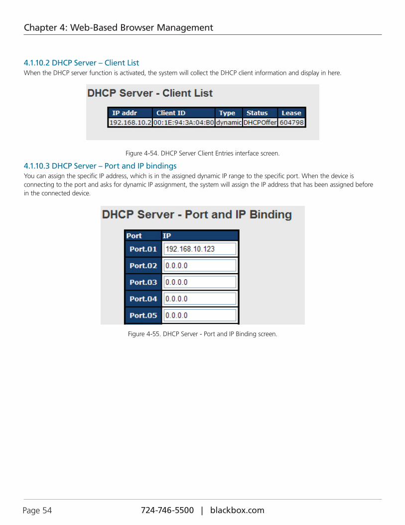
4.1.10.2 DHCP Server – Client ListWhen the DHCP server function is activated, the system will collect the DHCP client information and display in here.
Figure 4-54. DHCP Server Client Entries interface screen.
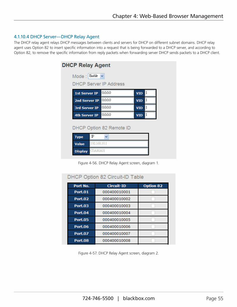
4.1.10.3 DHCP Server – Port and IP bindingsYou can assign the specific IP address, which is in the assigned dynamic IP range to the specific port. When the device is connecting to the port and asks for dynamic IP assignment, the system will assign the IP address that has been assigned before in the connected device.
Figure 4-55. DHCP Server - Port and IP Binding screen.
724-746-5500 | blackbox.com Page 55
Chapter 4: Web-Based Browser Management
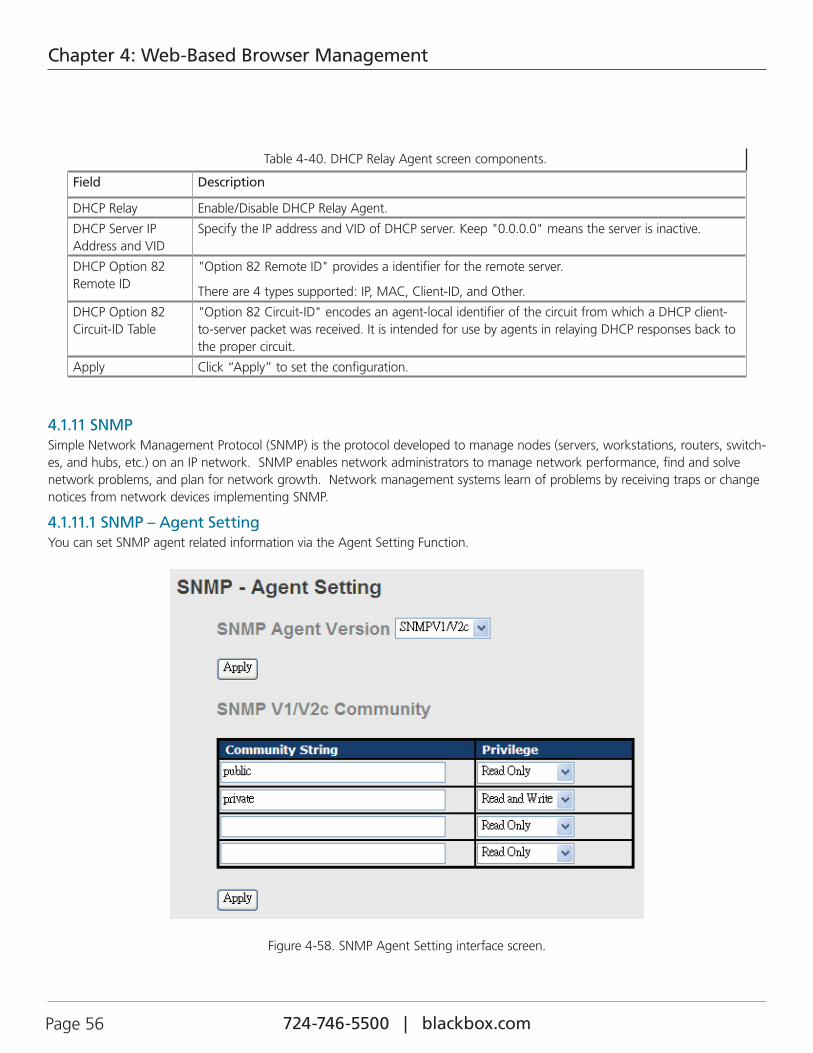
4.1.10.4 DHCP Server—DHCP Relay AgentThe DHCP relay agent relays DHCP messages between clients and servers for DHCP on different subnet domains. DHCP relay agent uses Option 82 to insert specific information into a request that is being forwarded to a DHCP server, and according to Option 82, to remove the specific information from reply packets when forwarding server DHCP sends packets to a DHCP client.
Figure 4-56. DHCP Relay Agent screen, diagram 1.
Figure 4-57. DHCP Relay Agent screen, diagram 2.
724-746-5500 | blackbox.com Page 56
Chapter 4: Web-Based Browser Management
Table 4-40. DHCP Relay Agent screen components.
Field Description
DHCP Relay Enable/Disable DHCP Relay Agent.
DHCP Server IP Address and VID
Specify the IP address and VID of DHCP server. Keep "0.0.0.0" means the server is inactive.
DHCP Option 82 Remote ID
"Option 82 Remote ID" provides a identifier for the remote server.
There are 4 types supported: IP, MAC, Client-ID, and Other.
DHCP Option 82 Circuit-ID Table
"Option 82 Circuit-ID" encodes an agent-local identifier of the circuit from which a DHCP client-to-server packet was received. It is intended for use by agents in relaying DHCP responses back to the proper circuit.
Apply Click “Apply” to set the configuration.
4.1.11 SNMPSimple Network Management Protocol (SNMP) is the protocol developed to manage nodes (servers, workstations, routers, switch-es, and hubs, etc.) on an IP network. SNMP enables network administrators to manage network performance, find and solve network problems, and plan for network growth. Network management systems learn of problems by receiving traps or change notices from network devices implementing SNMP.
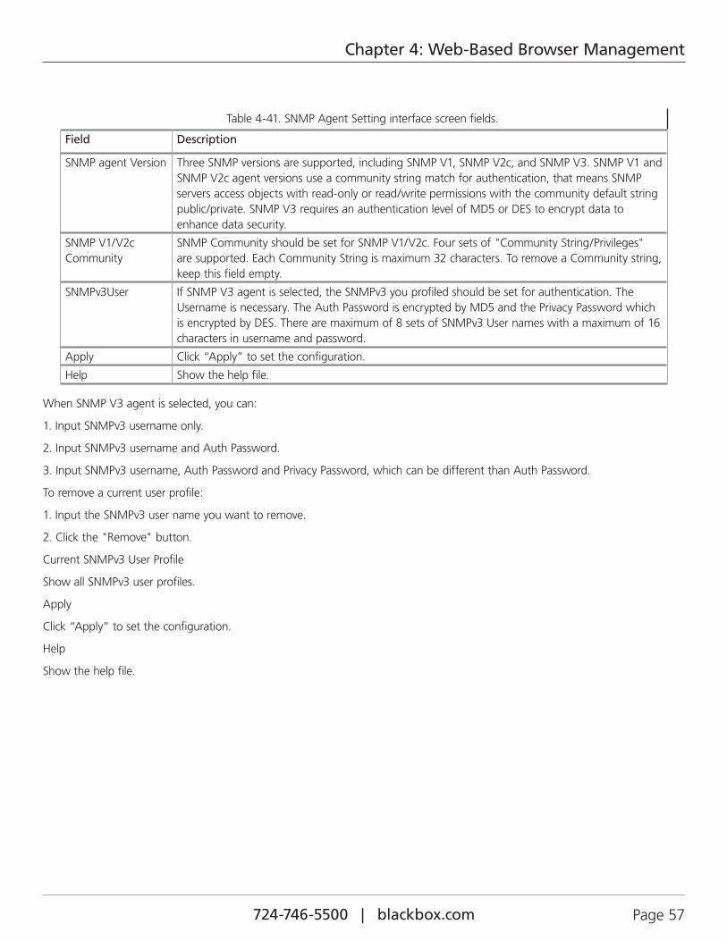
4.1.11.1 SNMP – Agent SettingYou can set SNMP agent related information via the Agent Setting Function.
Figure 4-58. SNMP Agent Setting interface screen.
724-746-5500 | blackbox.com Page 57
Chapter 4: Web-Based Browser Management
Table 4-41. SNMP Agent Setting interface screen fields.
Field Description
SNMP agent Version Three SNMP versions are supported, including SNMP V1, SNMP V2c, and SNMP V3. SNMP V1 and SNMP V2c agent versions use a community string match for authentication, that means SNMP servers access objects with read-only or read/write permissions with the community default string public/private. SNMP V3 requires an authentication level of MD5 or DES to encrypt data to enhance data security.
SNMP V1/V2c Community
SNMP Community should be set for SNMP V1/V2c. Four sets of "Community String/Privileges" are supported. Each Community String is maximum 32 characters. To remove a Community string, keep this field empty.
SNMPv3User If SNMP V3 agent is selected, the SNMPv3 you profiled should be set for authentication. The Username is necessary. The Auth Password is encrypted by MD5 and the Privacy Password which is encrypted by DES. There are maximum of 8 sets of SNMPv3 User names with a maximum of 16 characters in username and password.
Apply Click “Apply” to set the configuration.
Help Show the help file.
When SNMP V3 agent is selected, you can:
1. Input SNMPv3 username only.
2. Input SNMPv3 username and Auth Password.
3. Input SNMPv3 username, Auth Password and Privacy Password, which can be different than Auth Password.
To remove a current user profile:
1. Input the SNMPv3 user name you want to remove.
2. Click the "Remove" button.
Current SNMPv3 User Profile
Show all SNMPv3 user profiles.
Apply
Click “Apply” to set the configuration.
Help
Show the help file.
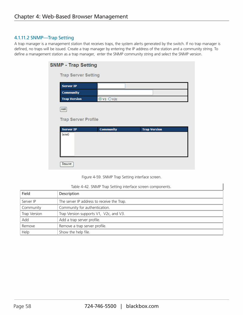
724-746-5500 | blackbox.com Page 58
Chapter 4: Web-Based Browser Management
4.1.11.2 SNMP—Trap SettingA trap manager is a management station that receives traps, the system alerts generated by the switch. If no trap manager is defined, no traps will be issued. Create a trap manager by entering the IP address of the station and a community string. To define a management station as a trap manager, enter the SNMP community string and select the SNMP version.
Figure 4-59. SNMP Trap Setting interface screen.
Table 4-42. SNMP Trap Setting interface screen components.
Field Description
Server IP The server IP address to receive the Trap.
Community Community for authentication.
Trap Version Trap Version supports V1, V2c, and V3.
Add Add a trap server profile.
Remove Remove a trap server profile.
Help Show the help file.
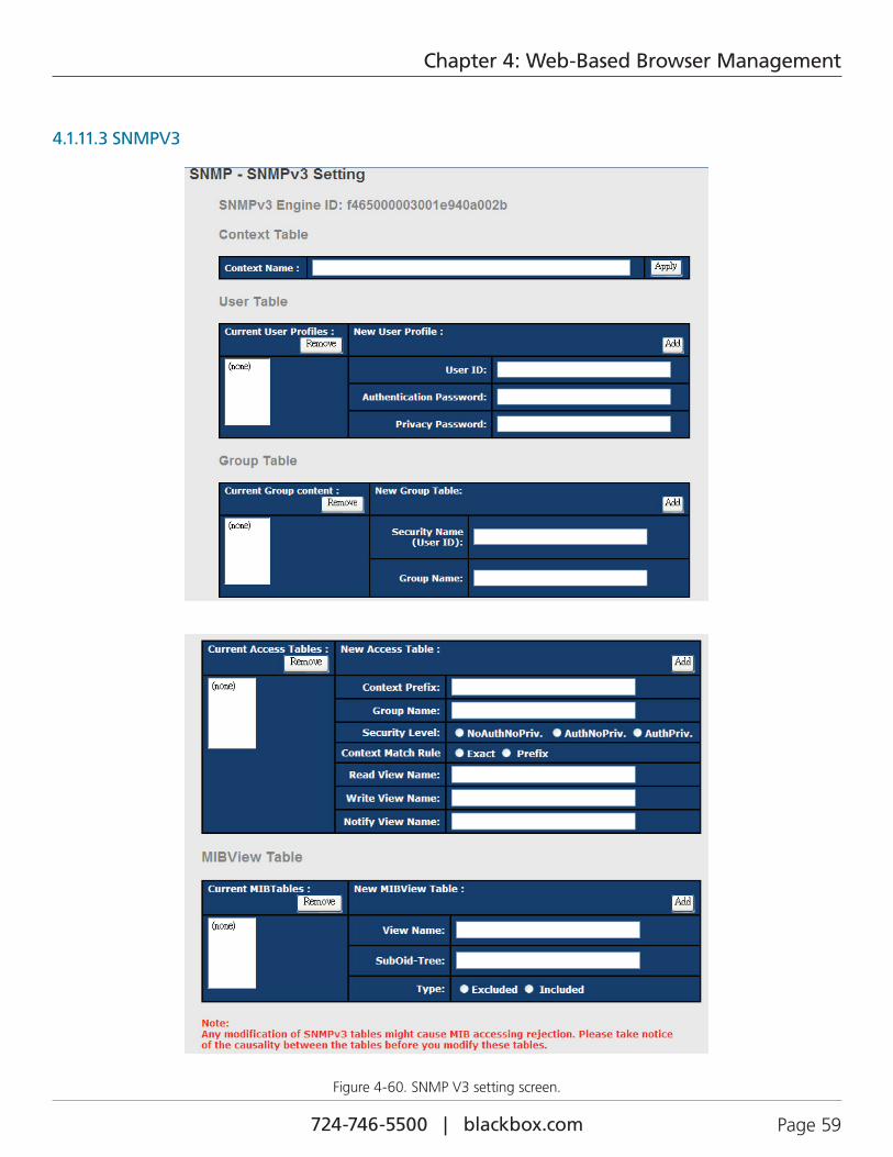
724-746-5500 | blackbox.com Page 59
Chapter 4: Web-Based Browser Management
4.1.11.3 SNMPV3
Figure 4-60. SNMP V3 setting screen.
724-746-5500 | blackbox.com Page 60
Chapter 4: Web-Based Browser Management
Table 4-43. SNMP V3 Setting screen options.
Field Description
Context Table Configure SNMP v3 context table. Assign the context name of the context table. Click "Apply" to change the context name.
User Table 1. Configure SNMP v3 user table. 2. User ID: set up the user name. 3. Authentication Password: set up the authentication password. 4. Privacy Password: set up the private password. 5. Click "Add" to add a context name. 6. Click "Remove" to remove an unwanted context name.
Group Table 1. Configure the SNMP v3 group table. 2. Security Name (User ID): assign the user name that you have set up in the user table. 3. Group Name: set up the group name. 4. Click "Add" to add the context name. 5. Click "Remove" to remove an unwanted context name.
Access Table 1. Configure the SNMP v3 access table. 2. Context Prefix: set up the context name. 3. Group Name: set up the group. 4. Security Level: select the access level. 5. Context Match Rule: select the context match rule. 6. Read View Name: set up the read view. 7. Write View Name: set up the write view. 8. Notify View Name: set up the notify view. 9. Click "Add" to add a context name. 10. Click "Remove" to remove an unwanted context name.
MIBview Table 1. Configure MIB view table. 2. ViewName: set up the name. 3. Sub-Oid Tree: fill the Sub OID. 4. Type: select the type —exclude or included. 5. Click "Add" to add context name. 6. Click "Remove" to remove unwanted context name.
Help Show the help file.
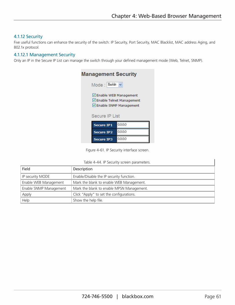
724-746-5500 | blackbox.com Page 61
Chapter 4: Web-Based Browser Management
4.1.12 SecurityFive useful functions can enhance the security of the switch: IP Security, Port Security, MAC Blacklist, MAC address Aging, and 802.1x protocol.
4.1.12.1 Management SecurityOnly an IP in the Secure IP List can manage the switch through your defined management mode (Web, Telnet, SNMP).
Figure 4-61. IP Security interface screen.
Table 4-44. IP Security screen parameters.
Field Description
IP security MODE Enable/Disable the IP security function.
Enable WEB Management Mark the blank to enable WEB Management.
Enable SNMP Management Mark the blank to enable MPSN Management.
Apply Click “Apply” to set the configurations.
Help Show the help file.
724-746-5500 | blackbox.com Page 62
Chapter 4: Web-Based Browser Management
4.1.12.2 Static MAC Forwarding Static MAC Forwarding adds static MAC addresses to hardware forwarding database. If port security is enabled at the Port Control page, only the frames with MAC addresses in this list will be forwarded; otherwise, they will be discarded.
Figure 4-62. Port Security interface screen.
Table 4-45. Port Security interface screen fields.
Field Description
MAC Address Input a MAC Address to a specific port.
Port No. Select a port on the switch.
Add Type in a MAC address and select a port number from the drop down box, then click on the Add button.
Delete Delete the entry.
Help Show the help file.
724-746-5500 | blackbox.com Page 63
Chapter 4: Web-Based Browser Management
4.1.12.3 MAC BlacklistMAC Blacklist can eliminate the traffic forwarding to specific MAC addresses in list. Any frames forwarded to MAC addresses in this list will be discarded. Thus the target device will never receive any frame.
Figure 4-63. MAC Blacklist interface screen.
Table 4-46. MAC Blacklist interface screen options.
Field Description
MAC Address Input a MAC Address to add to the MAC Blacklist.
Port No. Select a switch port.
Add Add an entry to the Blacklist table.
Delete Delete the entry.
Help Show the help file.
724-746-5500 | blackbox.com Page 64
Chapter 4: Web-Based Browser Management
4.1.12.4 802.1x802.1x uses the physical access characteristics of IEEE802 LAN infrastructures to provide authenticated and authorized devices attached to a LAN port. Refer to IEEE 802.1X—Port Based Network Access Control.
Figure 4-64. 802.1x Radius Server interface.
Table 4-47. 802.1x Radius Server interface screen parameters.
Field Description
802.1x Protocol Enable or Disable 802.1x Radius server function.
Radius Server IP The IP address of the authentication server.
Server port Set the UDP port number used by the authentication server to authenticate.
Account port Set the UDP destination port for accounting requests to the specified Radius Server.
Shared Key A key shared between this switch and authentication server.
NAS, Identifier A string used to identify this switch.
Quiet Period Set the time interval between authentication failure and the start of a new authentication attempt.
Tx Period Set the time that the switch can wait for response to an EAP request/identity frame from the client before resending the request.
Supplicant Timeout Set the period of time the switch waits for a supplicant response to an EAP request.
Server Timeout Set the period of time the switch waits for a Radius server response to an authentication request.
Max Requests Set the maximum number of times to retry sending packets to the supplicant.
Re-Auth Period Set the period of time after which clients connected must be re-authenticated.
Apply Click “Apply” to set the configuration.
Help Show the help file.
724-746-5500 | blackbox.com Page 65
Chapter 4: Web-Based Browser Management
802.1x-Port Authorized Mode
Set the 802.1x authorized mode of each port.
Figure 4-65. 802.1x Port Authorize interface screen.
Table 4-48. 802.1x Port Authorize interface screen parameters.
Field Description
Port Authorized Mode • Reject: Force this port to be unauthorized. • Accept: Force this port to be authorized. • Authorize: The state of this port was determined by the outcome of the 802.1x authentication. • Disable: This port will not participate in 802.1x.
Apply Click “Apply” to set the configuration.
Help Show the help file.
802.1x-Port Authorized Mode
Show 802.1x port authorized state.
Figure 4-66. 802.1x Port Authorize State interface screen.
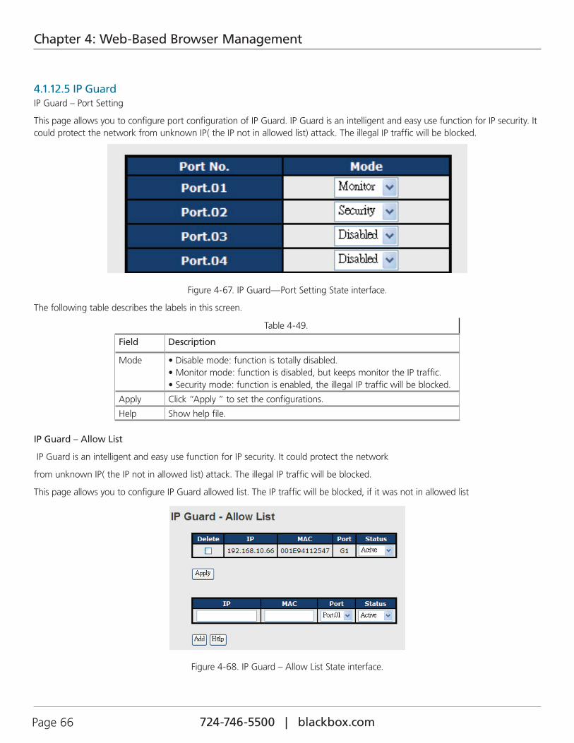
724-746-5500 | blackbox.com Page 66
Chapter 4: Web-Based Browser Management
4.1.12.5 IP GuardIP Guard – Port Setting
This page allows you to configure port configuration of IP Guard. IP Guard is an intelligent and easy use function for IP security. It could protect the network from unknown IP( the IP not in allowed list) attack. The illegal IP traffic will be blocked.
Figure 4-67. IP Guard—Port Setting State interface.
The following table describes the labels in this screen.
Table 4-49.
Field Description
Mode • Disable mode: function is totally disabled. • Monitor mode: function is disabled, but keeps monitor the IP traffic. • Security mode: function is enabled, the illegal IP traffic will be blocked.
Apply Click “Apply ” to set the configurations.
Help Show help file.
IP Guard – Allow List
IP Guard is an intelligent and easy use function for IP security. It could protect the network
from unknown IP( the IP not in allowed list) attack. The illegal IP traffic will be blocked.
This page allows you to configure IP Guard allowed list. The IP traffic will be blocked, if it was not in allowed list
Figure 4-68. IP Guard – Allow List State interface.
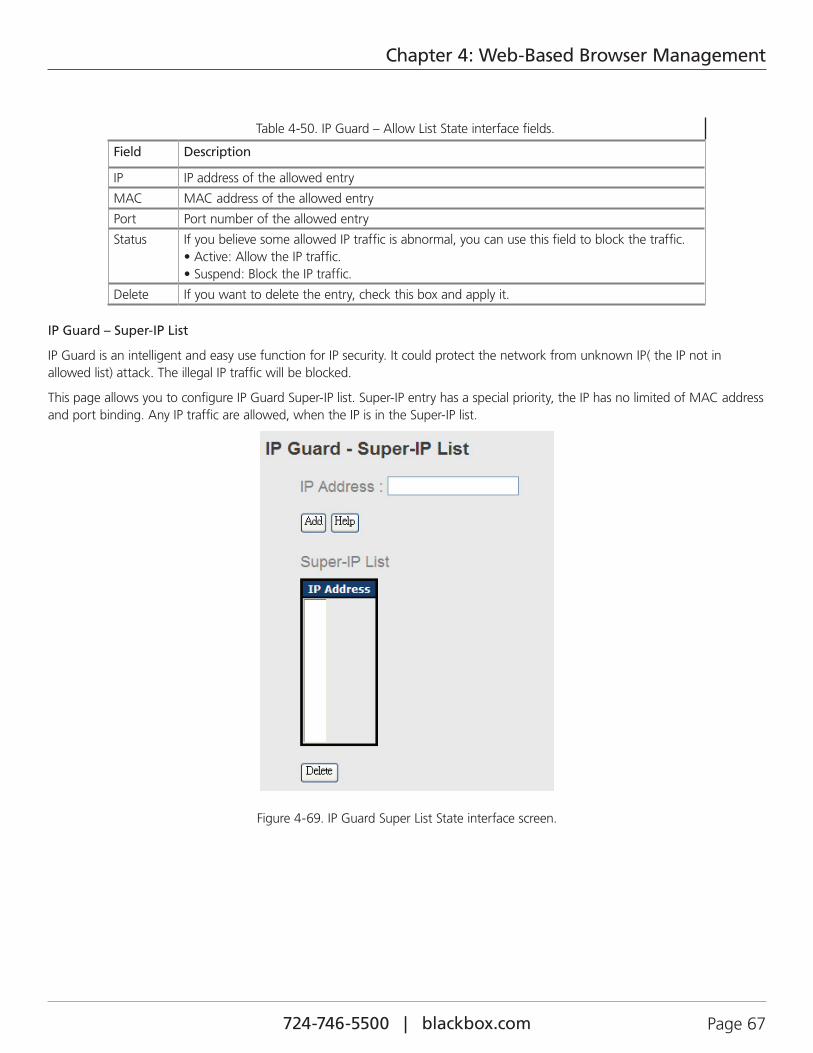
724-746-5500 | blackbox.com Page 67
Chapter 4: Web-Based Browser Management
Table 4-50. IP Guard – Allow List State interface fields.
Field Description
IP IP address of the allowed entry
MAC MAC address of the allowed entry
Port Port number of the allowed entry
Status If you believe some allowed IP traffic is abnormal, you can use this field to block the traffic. • Active: Allow the IP traffic. • Suspend: Block the IP traffic.
Delete If you want to delete the entry, check this box and apply it.
IP Guard – Super-IP List
IP Guard is an intelligent and easy use function for IP security. It could protect the network from unknown IP( the IP not in allowed list) attack. The illegal IP traffic will be blocked.
This page allows you to configure IP Guard Super-IP list. Super-IP entry has a special priority, the IP has no limited of MAC address and port binding. Any IP traffic are allowed, when the IP is in the Super-IP list.
Figure 4-69. IP Guard Super List State interface screen.
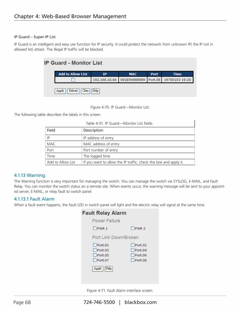
724-746-5500 | blackbox.com Page 68
Chapter 4: Web-Based Browser Management
IP Guard – Super-IP List
IP Guard is an intelligent and easy use function for IP security. It could protect the network from unknown IP( the IP not in allowed list) attack. The illegal IP traffic will be blocked.
Figure 4-70. IP Guard—Monitor List.
The following table describes the labels in this screen.
Table 4-51. IP Guard—Monitor List fields.
Field Description
IP IP address of entry
MAC MAC address of entry
Port Port number of entry
Time The logged time
Add to Allow List If you want to allow the IP traffic, check this box and apply it.
4.1.13 WarningThe Warning function is very important for managing the switch. You can manage the switch via SYSLOG, E-MAIL, and Fault Relay. You can monitor the switch status on a remote site. When events occur, the warning message will be sent to your appoint-ed server, E-MAIL, or relay fault to switch panel.
4.1.13.1 Fault Alarm When a fault event happens, the Fault LED in switch panel will light and the electric relay will signal at the same time.
Figure 4-71. Fault Alarm interface screen.
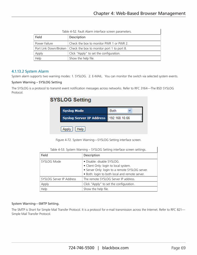
724-746-5500 | blackbox.com Page 69
Chapter 4: Web-Based Browser Management
Table 4-52. Fault Alarm interface screen parameters.
Field Description
Power Failure Check the box to monitor PWR 1 or PWR 2.
Port Link Down/Broken Check the box to monitor port 1 to port 8.
Apply Click “Apply” to set the configuration.
Help Show the help file.
4.1.13.2 System Alarm System alarm supports two warning modes: 1. SYSLOG. 2. E-MAIL. You can monitor the switch via selected system events.
System Warning – SYSLOG Setting
The SYSLOG is a protocol to transmit event notification messages across networks. Refer to RFC 3164—The BSD SYSLOG Protocol.
Figure 4-72. System Warning—SYSLOG Setting interface screen.
Table 4-53. System Warning – SYSLOG Setting interface screen settings.
Field Description
SYSLOG Mode • Disable: disable SYSLOG. • Client Only: login to local system. • Server Only: login to a remote SYSLOG server. • Both: login to both local and remote server.
SYSLOG Server IP Address The remote SYSLOG Server IP address.
Apply Click “Apply” to set the configuration.
Help Show the help file.
System Warning—SMTP Setting.
The SMTP is Short for Simple Mail Transfer Protocol. It is a protocol for e-mail transmission across the Internet. Refer to RFC 821—Simple Mail Transfer Protocol.
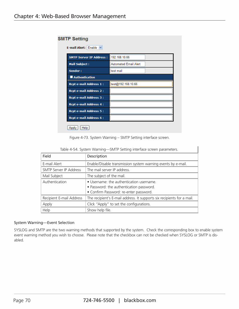
724-746-5500 | blackbox.com Page 70
Chapter 4: Web-Based Browser Management
Figure 4-73. System Warning – SMTP Setting interface screen.
Table 4-54. System Warning—SMTP Setting interface screen parameters.
Field Description
E-mail Alert Enable/Disable transmission system warning events by e-mail.
SMTP Server IP Address The mail server IP address.
Mail Subject The subject of the mail.
Authentication • Username: the authentication username. • Password: the authentication password. • Confirm Password: re-enter password.
Recipient E-mail Address The recipient's E-mail address. It supports six recipients for a mail.
Apply Click “Apply” to set the configurations.
Help Show help file.
System Warning—Event Selection
SYSLOG and SMTP are the two warning methods that supported by the system. Check the corresponding box to enable system event warning method you wish to choose. Please note that the checkbox can not be checked when SYSLOG or SMTP is dis-abled.
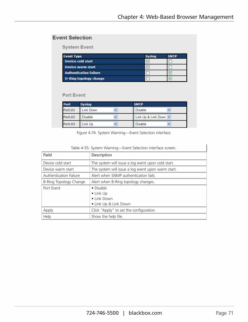
724-746-5500 | blackbox.com Page 71
Chapter 4: Web-Based Browser Management
Figure 4-74. System Warning—Event Selection interface.
Table 4-55. System Warning—Event Selection interface screen.
Field Description
Device cold start The system will issue a log event upon cold start.
Device warm start The system will issue a log event upon warm start.
Authentication Failure Alert when SNMP authentication fails.
B-Ring Topology Change Alert when B-Ring topology changes.
Port Event • Disable • Link Up • Link Down • Link Up & Link Down
Apply Click “Apply” to set the configuration.
Help Show the help file.
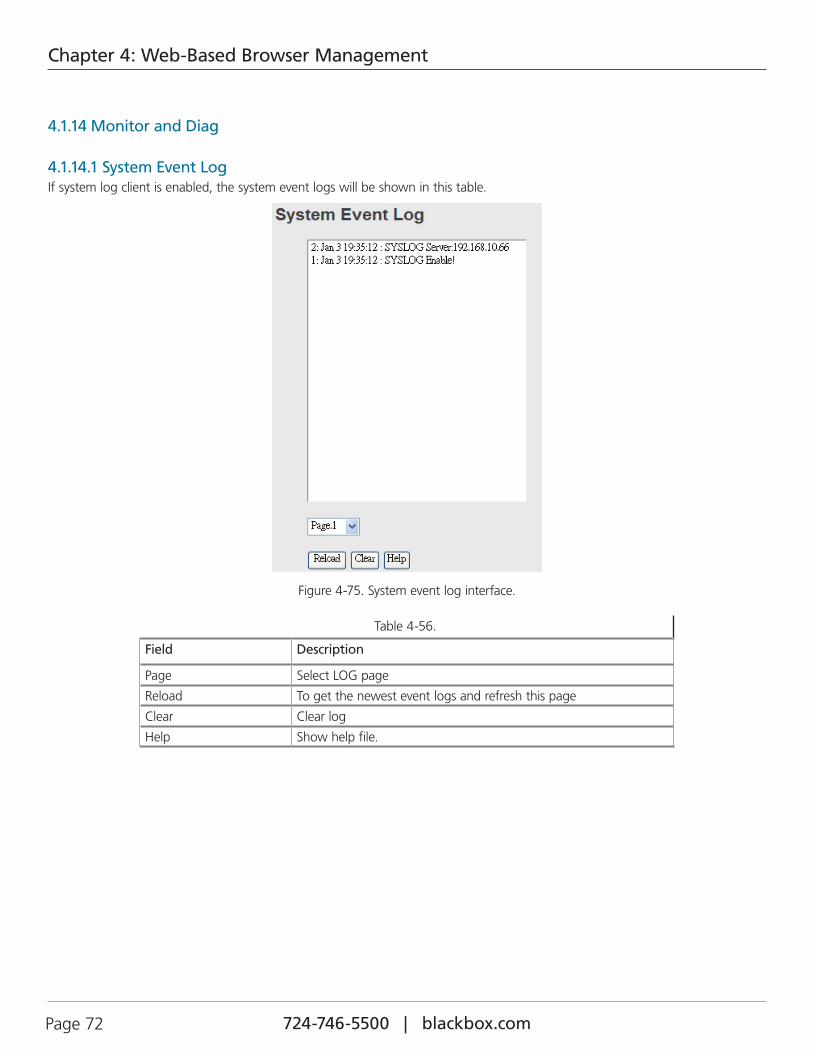
724-746-5500 | blackbox.com Page 72
Chapter 4: Web-Based Browser Management
4.1.14 Monitor and Diag
4.1.14.1 System Event LogIf system log client is enabled, the system event logs will be shown in this table.
Figure 4-75. System event log interface.
Table 4-56.
Field Description
Page Select LOG page
Reload To get the newest event logs and refresh this page
Clear Clear log
Help Show help file.
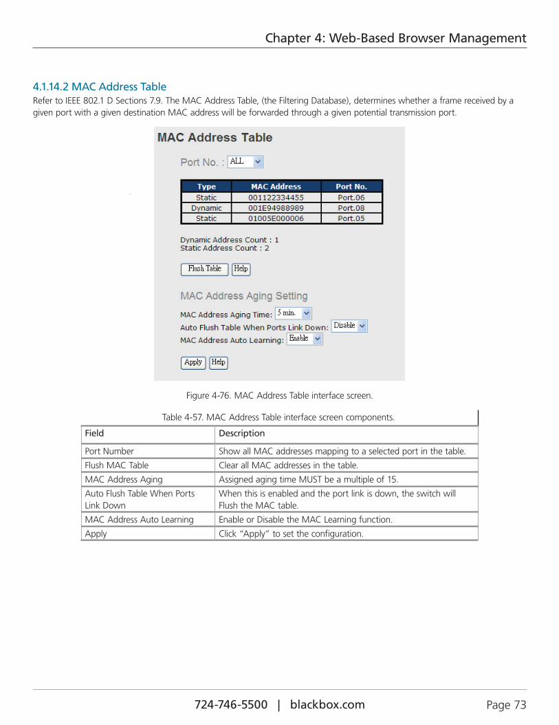
724-746-5500 | blackbox.com Page 73
Chapter 4: Web-Based Browser Management
4.1.14.2 MAC Address TableRefer to IEEE 802.1 D Sections 7.9. The MAC Address Table, (the Filtering Database), determines whether a frame received by a given port with a given destination MAC address will be forwarded through a given potential transmission port.
Figure 4-76. MAC Address Table interface screen.
Table 4-57. MAC Address Table interface screen components.
Field Description
Port Number Show all MAC addresses mapping to a selected port in the table.
Flush MAC Table Clear all MAC addresses in the table.
MAC Address Aging Assigned aging time MUST be a multiple of 15.
Auto Flush Table When Ports Link Down
When this is enabled and the port link is down, the switch will Flush the MAC table.
MAC Address Auto Learning Enable or Disable the MAC Learning function.
Apply Click “Apply” to set the configuration.
724-746-5500 | blackbox.com Page 74
Chapter 4: Web-Based Browser Management
4.1.14.3 Port OverviewPort statistics show several statistics counters for all ports.
Figure 4-77. Port Overview screen.
Table 4-58. Port Overview screen options.
Field Description
Type Show port speed and media type.
Link Show port link status.
State Show ports enabled or disabled.
TX GOOD Packet The number of good packets sent by this port.
TX Bad Packet The number of bad packets sent by this port.
RX GOOD Packet The number of good packets received by this port.
RX Bad Packet The number of bad packets received by this port.
TX Abort Packet The number of packets aborted by this port.
Packet Collision The number of times a collision detected by this port.
Clear Clear all counters.
Help Show help file.
724-746-5500 | blackbox.com Page 75
Chapter 4: Web-Based Browser Management
4.1.14.4 Port CountersThis page shows statistic counters for the port. The "Clear" button is to reset all counters to zero for all ports.
Figure 4-78. Port Counters interface screen.
Table 4-59. Port Counters interface screen options.
Field Description
InGoodOctetsLo The lower 32-bits of the 64-bit InGoodOctets counter. The sum of lengths of all good Ethernet frames received, that is, frames that are not bad frames.
InGoodOctetsHi The upper 32-bits of the 64-bit InGoodOctets counter. The sum of lengths of all good Ethernet frames received, that is frames that are not bad frames.
InBadOctets The sum of lengths of all bad Ethernet frames received.
OutFCSErr The number of frames transmitted with a invalid FCS. Whenever a frame is modified during transmission (e.g., to add or remove a tag) the frames’s original FCS is inspected before a new FCS is added to a modi-fied frame. If the original FCS is invalid, the newFCS is made invalid too and this counter is incremented.
InUnicasts The number of good frames received that have a Unicast destination MAC address.
Deferred The total number of successfully transmitted frames that experienced no collisions but are delayed because the medium was busy during the first attempt. This counter is applicable in half-duplex mode only.
InBroadcasts The number of good frames received that have a Broadcast destination MAC address.
InMulticasts The number of good frames received that have a Multicast destination MAC address.
Octets64 Total frames received (and/or transmitted) with a length of exactly 64 octets, including those with errors.
Octets127 Total frames received (and/or transmitted) with a length of between 65 and 127 octets inclusive, including those with errors.
Octets255 Total frames received (and/or transmitted) with a length of between 128 and 255 octets inclusive, including those with error.
Octets511 Total frames received (and/or transmitted) with a length of between 256 and 511 octets inclusive, including those with error.
Octets1023 Total frames received (and/or transmitted) with a length of between 512 and 1023 octets inclusive, including those with error.
724-746-5500 | blackbox.com Page 76
Chapter 4: Web-Based Browser Management
Table 4-59 (continued). Port Counters interface screen options.
Field Description
OctetsMax Total frames received (and/or transmitted) with a length of between 1024 and MaxSize octets inclusive, including those with error.
OutOctetsLo The lower 32-bit of the 64-bit OutOctets counter. The sum of lengths of all Ethernet frames sent from this MAC.
OutOctetsHi The upper 32-bit of the 64-bit OutOctets counter. The sum of lengths of all Ethernet frames sent from this MAC.
OutUnicasts The number of frames sent that have an Unicast destination MAC address.
Excessive The number frames dropped in the transmit MAC because the frame experienced 16 consecutive collisions. This counter is applicable in half-duplex only and only if DiscardExcessive is one.
OutBroadcasts The number of good frames sent that have a Broadcast destination MAC address.
Single The total number of successfully transmitted frames that experienced exactly one collision. This counter is applicable in half-duplex only.
OutPause The number of good Flow Control frames sent.
InPause The number of good Flow Control frames received.
Multiple The total number of successfully transmitted frames that experienced more than one collision. This counter is applicable in half-duplex only.
Undersize Total frames received with a length of less than 64 octets, but with a valid FCS.
Fragments Total frames received with a length of more than 64 octets and with an invalid FCS.
Oversize Total frames received with a length of more than MaxSize octets, but with a valid FCS.
Jabber Total frames received with a length of more than MaxSize octets, but with an invalid FCS.
InMACRcvErr Total frames received with an RxErr signal from the PHY.
InFCSErr Total frames received with a CRC error not counted in Fragments, Jabber, or RxErr.
Collisions The number of collision events seen by MAC not including those counted in Single, Multiple, Excessive or Late. This counter is applicable in half-duplex only.
Late The number of times a collision is detected later than 512 bits-times into the transmission of a frame. This counter is applicable in half-duplex mode only.
4.1.14.5 Port MonitoringPort monitoring supports TX (egress) only, RX (ingress) only, and TX/RX monitoring. TX monitoring sends any data that egress out checked TX source ports to a selected TX destination port as well. RX monitoring sends any data that ingress in checked RX source ports out to a selected RX destination port as well as sending the frame where it normally would have gone. Note that keep all source ports unchecked in order to disable port monitoring.
Figure 4-79. Port monitoring interface screen.
724-746-5500 | blackbox.com Page 77
Chapter 4: Web-Based Browser Management
Table 4-60. Port monitoring interface screen options.
Field Description
Destination Port The port will receive a copied frame from the source port for monitoring.
Source Port The port will be monitored. Mark TX or RX to monitor.
TX The frames transmitted from the switch port.
RX The frames receive by the switch port.
Apply Click “Apply” to set the configurations.
Clear Clear all blanks (disable the function).
Help Show the help file.
4.1.14.6 Traffic MonitorThe function can monitor switch traffic. If traffic is too large, the switch will send SYSLOG Event or SMTP Mail.
Figure 4-80. System event log interface screen.
Table 4-61. System event log interface screen components.
Field Description
Monitored –Counter Select monitor type
Time-Interval Setting Interval time
Increasing – Quantity Setting alarm Quantity
Event Alarm Select alarm function (SYSLOG or SMTP)
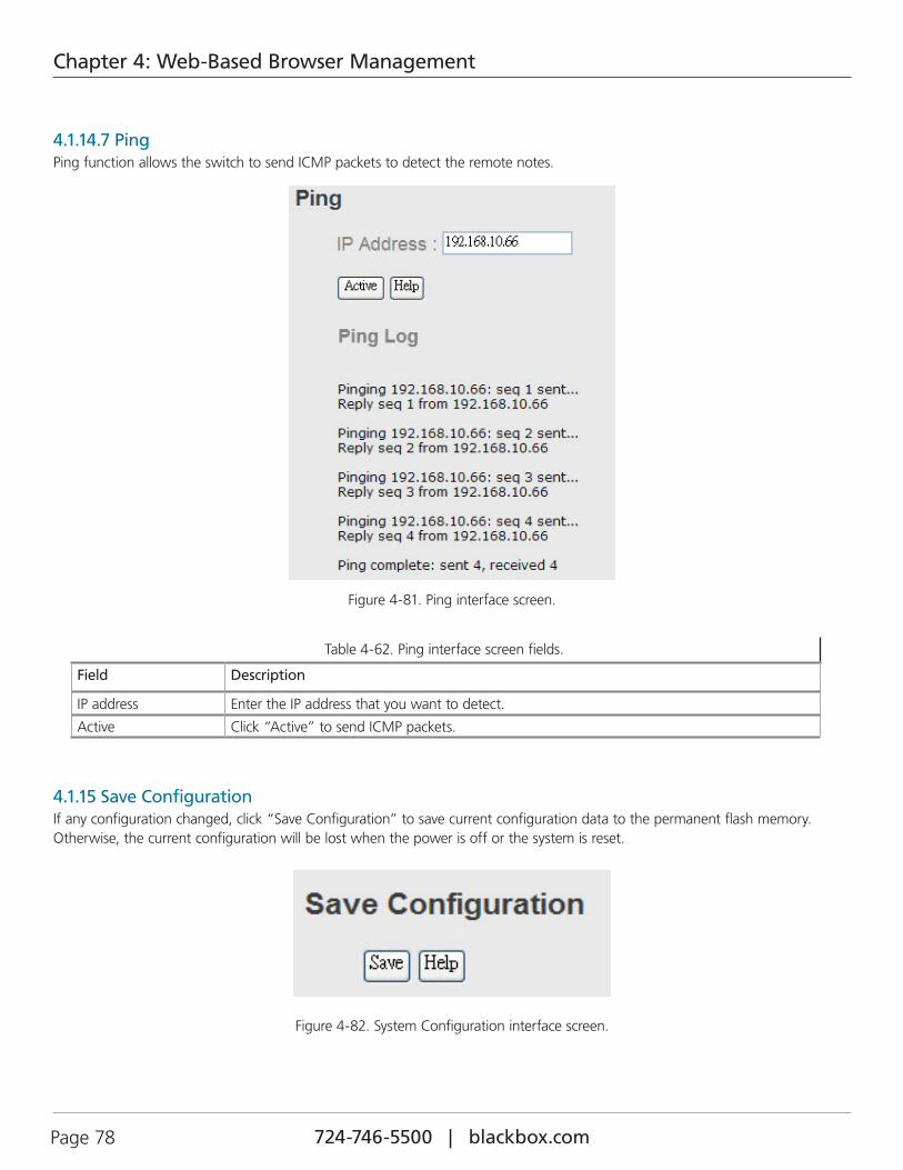
724-746-5500 | blackbox.com Page 78
Chapter 4: Web-Based Browser Management
4.1.14.7 PingPing function allows the switch to send ICMP packets to detect the remote notes.
Figure 4-81. Ping interface screen.
Table 4-62. Ping interface screen fields.
Field Description
IP address Enter the IP address that you want to detect.
Active Click “Active” to send ICMP packets.
4.1.15 Save ConfigurationIf any configuration changed, click “Save Configuration” to save current configuration data to the permanent flash memory. Otherwise, the current configuration will be lost when the power is off or the system is reset.
Figure 4-82. System Configuration interface screen.
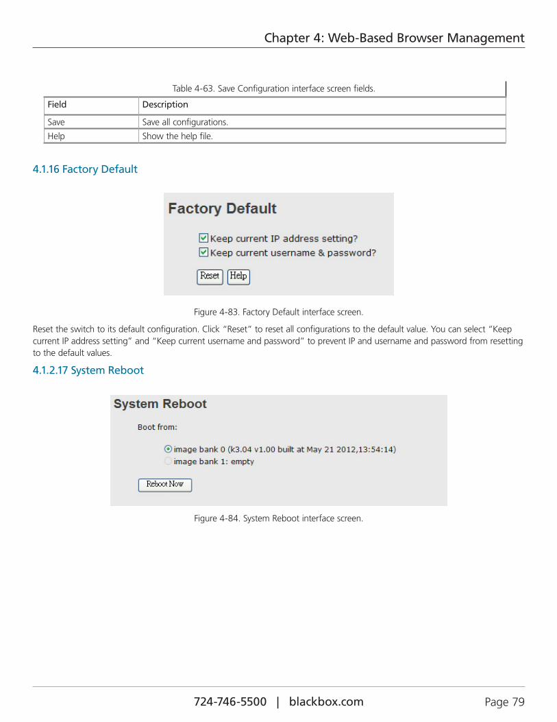
724-746-5500 | blackbox.com Page 79
Chapter 4: Web-Based Browser Management
Table 4-63. Save Configuration interface screen fields.
Field Description
Save Save all configurations.
Help Show the help file.
4.1.16 Factory Default
Figure 4-83. Factory Default interface screen.
Reset the switch to its default configuration. Click “Reset” to reset all configurations to the default value. You can select “Keep current IP address setting” and “Keep current username and password” to prevent IP and username and password from resetting to the default values.
4.1.2.17 System Reboot
Figure 4-84. System Reboot interface screen.
724-746-5500 | blackbox.com Page 80
Chapter 5: Command-Line Management
5. Command-Line Interface Management
5.1 About CLI ManagementThe Industrial Managed Gigabit Ethernet Switch supports Web-based and CLI management. You can use a console or telnet to manage the switch via CLI.
CLI Management Using a RS-232 Serial Console (9600, 8, none, 1, none)
Before Configuring by RS-232 serial console, use an RJ-45 to DB9F cable to connect the switch's RS-232 Console port to your PC’s COM port.
Follow the steps below to access the console via an RS-232 serial cable.
1. From the Windows desktop, click on Start -> Programs -> Accessories -> Communications -> Hyper Terminal
Figure 5-1. HyperTerminal screen.
2. Input a name for new connection.
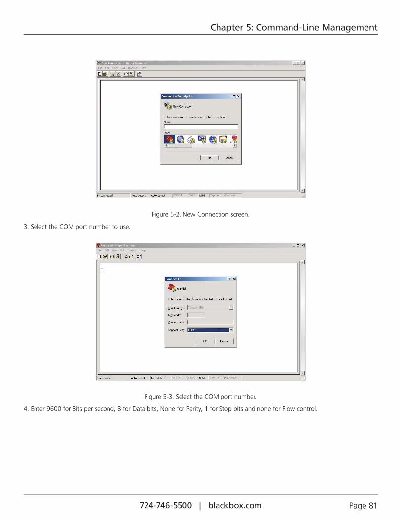
724-746-5500 | blackbox.com Page 81
Chapter 5: Command-Line Management
Figure 5-2. New Connection screen.
3. Select the COM port number to use.
Figure 5-3. Select the COM port number.
4. Enter 9600 for Bits per second, 8 for Data bits, None for Parity, 1 for Stop bits and none for Flow control.
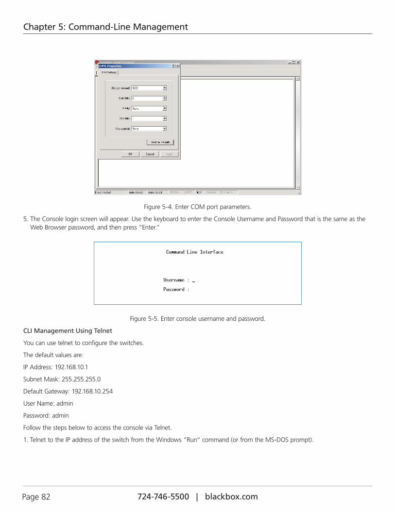
724-746-5500 | blackbox.com Page 82
Chapter 5: Command-Line Management
Figure 5-4. Enter COM port parameters.
5. The Console login screen will appear. Use the keyboard to enter the Console Username and Password that is the same as the Web Browser password, and then press “Enter.”
Figure 5-5. Enter console username and password.
CLI Management Using Telnet
You can use telnet to configure the switches.
The default values are:
IP Address: 192.168.10.1
Subnet Mask: 255.255.255.0
Default Gateway: 192.168.10.254
User Name: admin
Password: admin
Follow the steps below to access the console via Telnet.
1. Telnet to the IP address of the switch from the Windows “Run“ command (or from the MS-DOS prompt).
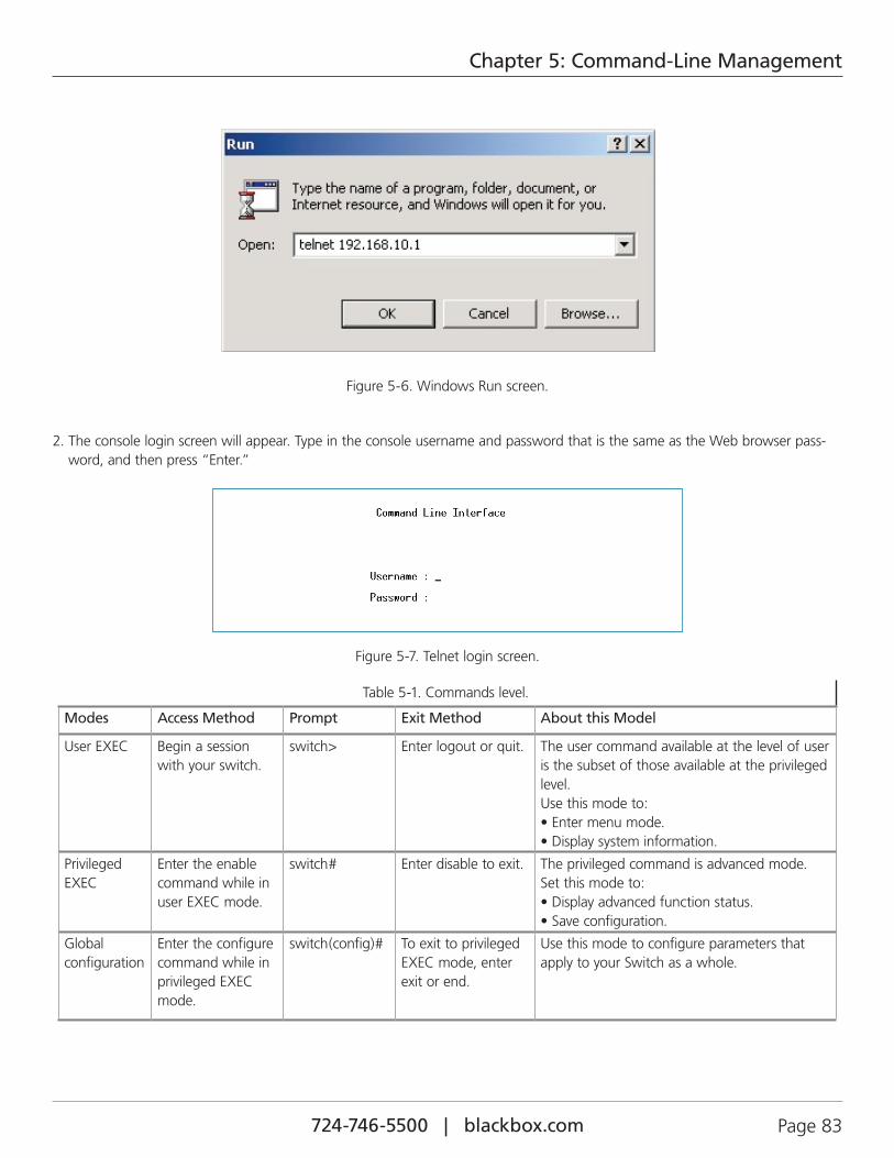
724-746-5500 | blackbox.com Page 83
Chapter 5: Command-Line Management
Figure 5-6. Windows Run screen.
2. The console login screen will appear. Type in the console username and password that is the same as the Web browser pass-word, and then press “Enter.”
Figure 5-7. Telnet login screen.
Table 5-1. Commands level.
Modes Access Method Prompt Exit Method About this Model
User EXEC Begin a session with your switch.
switch> Enter logout or quit. The user command available at the level of user is the subset of those available at the privileged level. Use this mode to: • Enter menu mode. • Display system information.
Privileged EXEC
Enter the enable command while in user EXEC mode.
switch# Enter disable to exit. The privileged command is advanced mode. Set this mode to: • Display advanced function status. • Save configuration.
Global configuration
Enter the configure command while in privileged EXEC mode.
switch(config)# To exit to privileged EXEC mode, enter exit or end.
Use this mode to configure parameters that apply to your Switch as a whole.
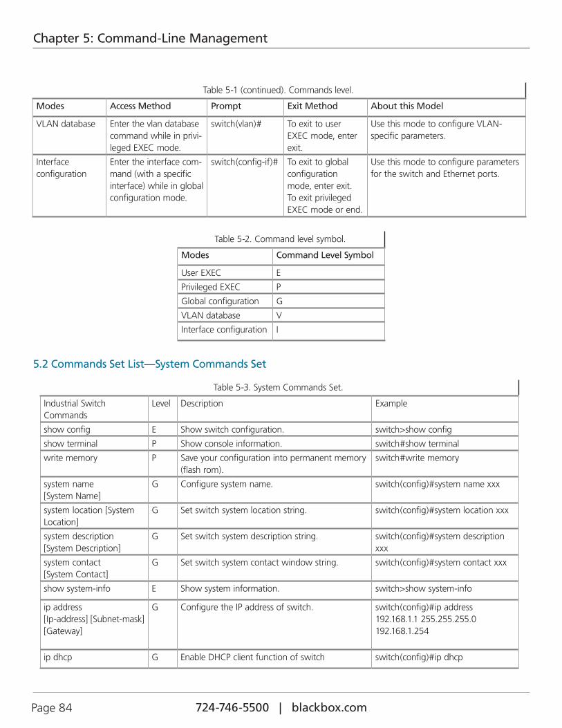
724-746-5500 | blackbox.com Page 84
Chapter 5: Command-Line Management
Table 5-1 (continued). Commands level.
Modes Access Method Prompt Exit Method About this Model
VLAN database Enter the vlan database command while in privi-leged EXEC mode.
switch(vlan)# To exit to user EXEC mode, enter exit.
Use this mode to configure VLAN-specific parameters.
Interface configuration
Enter the interface com-mand (with a specific interface) while in global configuration mode.
switch(config-if)# To exit to global configuration mode, enter exit. To exit privileged EXEC mode or end.
Use this mode to configure parameters for the switch and Ethernet ports.
Table 5-2. Command level symbol.
Modes Command Level Symbol
User EXEC E
Privileged EXEC P
Global configuration G
VLAN database V
Interface configuration I
5.2 Commands Set List—System Commands Set
Table 5-3. System Commands Set.
Industrial Switch Commands
Level Description Example
show config E Show switch configuration. switch>show config
show terminal P Show console information. switch#show terminal
write memory P Save your configuration into permanent memory (flash rom).
switch#write memory
system name [System Name]
G Configure system name. switch(config)#system name xxx
system location [System Location]
G Set switch system location string. switch(config)#system location xxx
system description [System Description]
G Set switch system description string. switch(config)#system description xxx
system contact [System Contact]
G Set switch system contact window string. switch(config)#system contact xxx
show system-info E Show system information. switch>show system-info
ip address [Ip-address] [Subnet-mask] [Gateway]
G Configure the IP address of switch. switch(config)#ip address 192.168.1.1 255.255.255.0 192.168.1.254
ip dhcp G Enable DHCP client function of switch switch(config)#ip dhcp
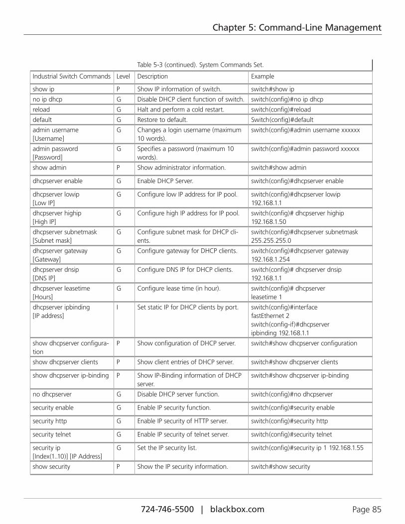
724-746-5500 | blackbox.com Page 85
Chapter 5: Command-Line Management
Table 5-3 (continued). System Commands Set.
Industrial Switch Commands Level Description Example
show ip P Show IP information of switch. switch#show ip
no ip dhcp G Disable DHCP client function of switch. switch(config)#no ip dhcp
reload G Halt and perform a cold restart. switch(config)#reload
default G Restore to default. Switch(config)#default
admin username [Username]
G Changes a login username (maximum 10 words).
switch(config)#admin username xxxxxx
admin password [Password]
G Specifies a password (maximum 10 words).
switch(config)#admin password xxxxxx
show admin P Show administrator information. switch#show admin
dhcpserver enable G Enable DHCP Server. switch(config)#dhcpserver enable
dhcpserver lowip [Low IP]
G Configure low IP address for IP pool. switch(config)#dhcpserver lowip 192.168.1.1
dhcpserver highip [High IP]
G Configure high IP address for IP pool. switch(config)# dhcpserver highip 192.168.1.50
dhcpserver subnetmask [Subnet mask]
G Configure subnet mask for DHCP cli-ents.
switch(config)#dhcpserver subnetmask 255.255.255.0
dhcpserver gateway [Gateway]
G Configure gateway for DHCP clients. switch(config)#dhcpserver gateway 192.168.1.254
dhcpserver dnsip [DNS IP]
G Configure DNS IP for DHCP clients. switch(config)# dhcpserver dnsip 192.168.1.1
dhcpserver leasetime [Hours]
G Configure lease time (in hour). switch(config)# dhcpserver leasetime 1
dhcpserver ipbinding [IP address]
I Set static IP for DHCP clients by port. switch(config)#interface fastEthernet 2 switch(config-if)#dhcpserver ipbinding 192.168.1.1
show dhcpserver configura-tion
P Show configuration of DHCP server. switch#show dhcpserver configuration
show dhcpserver clients P Show client entries of DHCP server. switch#show dhcpserver clients
show dhcpserver ip-binding P Show IP-Binding information of DHCP server.
switch#show dhcpserver ip-binding
no dhcpserver G Disable DHCP server function. switch(config)#no dhcpserver
security enable G Enable IP security function. switch(config)#security enable
security http G Enable IP security of HTTP server. switch(config)#security http
security telnet G Enable IP security of telnet server. switch(config)#security telnet
security ip [Index(1..10)] [IP Address]
G Set the IP security list. switch(config)#security ip 1 192.168.1.55
show security P Show the IP security information. switch#show security
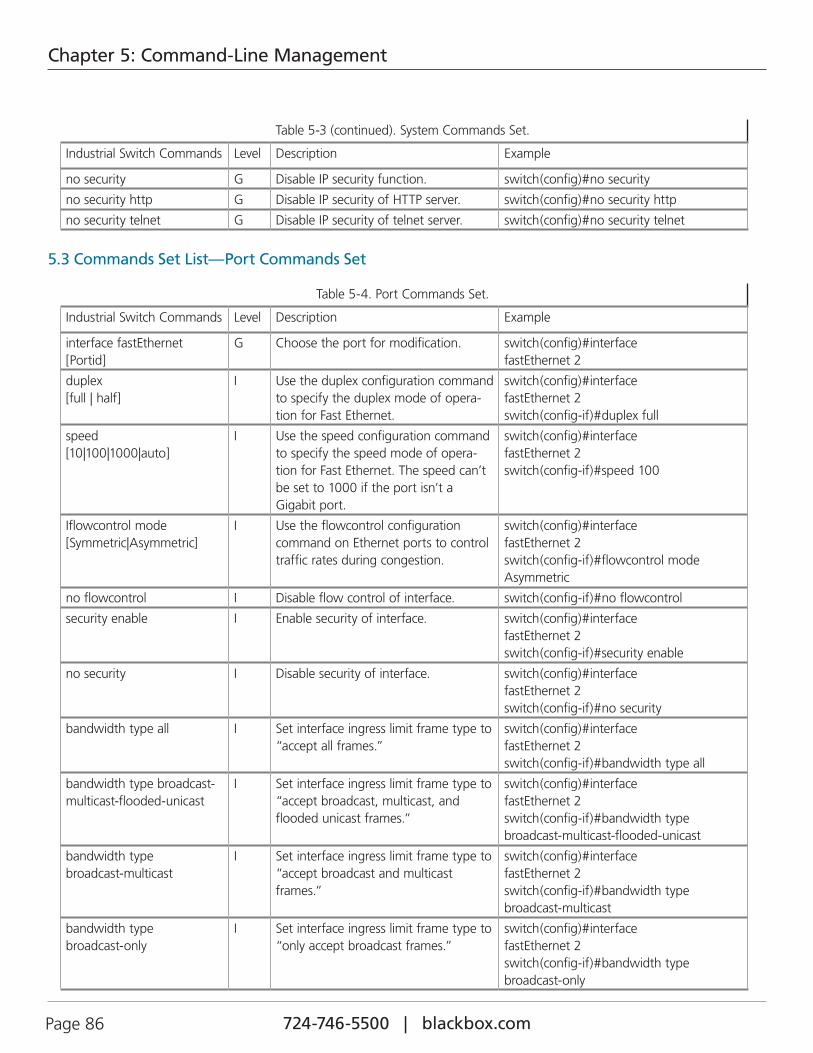
724-746-5500 | blackbox.com Page 86
Chapter 5: Command-Line Management
Table 5-3 (continued). System Commands Set.
Industrial Switch Commands Level Description Example
no security G Disable IP security function. switch(config)#no security
no security http G Disable IP security of HTTP server. switch(config)#no security http
no security telnet G Disable IP security of telnet server. switch(config)#no security telnet
5.3 Commands Set List—Port Commands Set
Table 5-4. Port Commands Set.
Industrial Switch Commands Level Description Example
interface fastEthernet [Portid]
G Choose the port for modification. switch(config)#interface fastEthernet 2
duplex [full | half]
I Use the duplex configuration command to specify the duplex mode of opera-tion for Fast Ethernet.
switch(config)#interface fastEthernet 2 switch(config-if)#duplex full
speed [10|100|1000|auto]
I Use the speed configuration command to specify the speed mode of opera-tion for Fast Ethernet. The speed can’t be set to 1000 if the port isn’t a Gigabit port.
switch(config)#interface fastEthernet 2 switch(config-if)#speed 100
Iflowcontrol mode [Symmetric|Asymmetric]
I Use the flowcontrol configuration command on Ethernet ports to control traffic rates during congestion.
switch(config)#interface fastEthernet 2 switch(config-if)#flowcontrol mode Asymmetric
no flowcontrol I Disable flow control of interface. switch(config-if)#no flowcontrol
security enable I Enable security of interface. switch(config)#interface fastEthernet 2 switch(config-if)#security enable
no security I Disable security of interface. switch(config)#interface fastEthernet 2 switch(config-if)#no security
bandwidth type all I Set interface ingress limit frame type to “accept all frames.”
switch(config)#interface fastEthernet 2 switch(config-if)#bandwidth type all
bandwidth type broadcast-multicast-flooded-unicast
I Set interface ingress limit frame type to “accept broadcast, multicast, and flooded unicast frames.”
switch(config)#interface fastEthernet 2 switch(config-if)#bandwidth type broadcast-multicast-flooded-unicast
bandwidth type broadcast-multicast
I Set interface ingress limit frame type to “accept broadcast and multicast frames.”
switch(config)#interface fastEthernet 2 switch(config-if)#bandwidth type broadcast-multicast
bandwidth type broadcast-only
I Set interface ingress limit frame type to “only accept broadcast frames.”
switch(config)#interface fastEthernet 2 switch(config-if)#bandwidth type broadcast-only
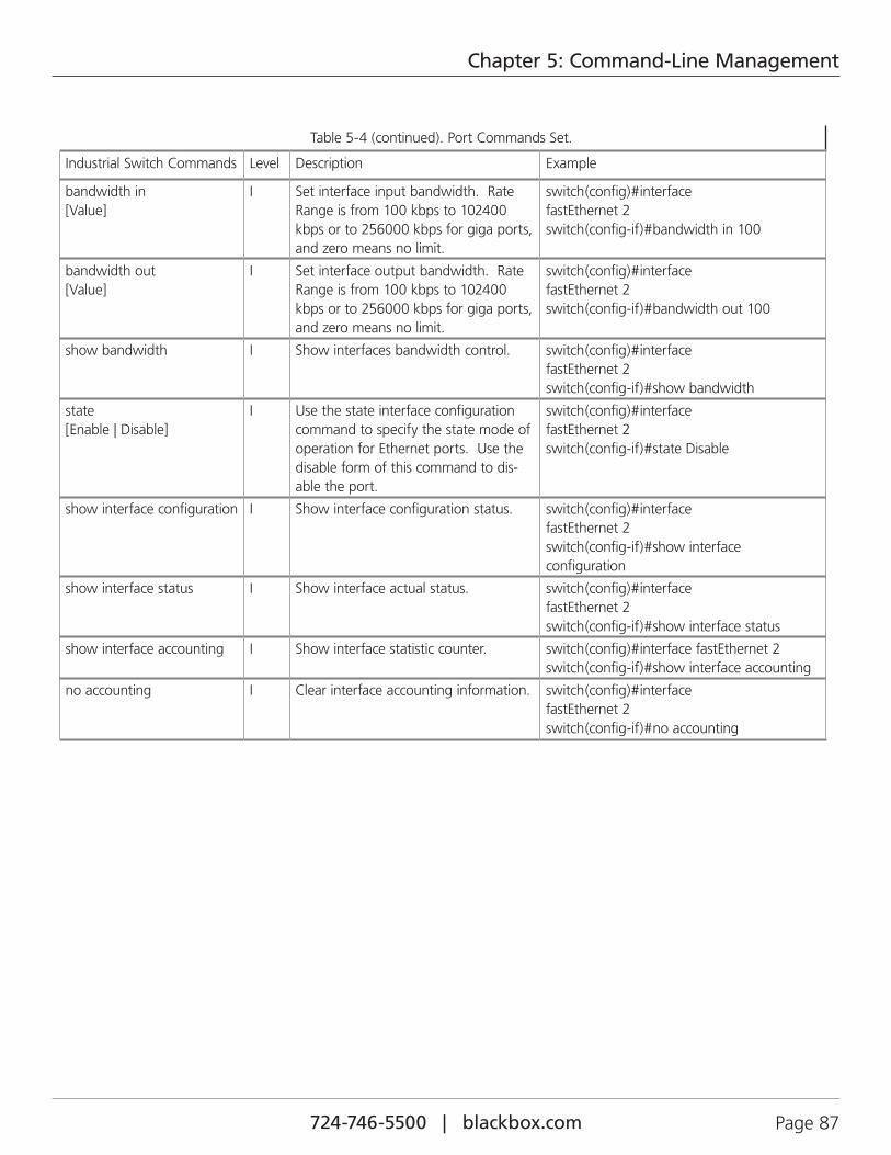
724-746-5500 | blackbox.com Page 87
Chapter 5: Command-Line Management
Table 5-4 (continued). Port Commands Set.
Industrial Switch Commands Level Description Example
bandwidth in [Value]
I Set interface input bandwidth. Rate Range is from 100 kbps to 102400 kbps or to 256000 kbps for giga ports, and zero means no limit.
switch(config)#interface fastEthernet 2 switch(config-if)#bandwidth in 100
bandwidth out [Value]
I Set interface output bandwidth. Rate Range is from 100 kbps to 102400 kbps or to 256000 kbps for giga ports, and zero means no limit.
switch(config)#interface fastEthernet 2 switch(config-if)#bandwidth out 100
show bandwidth I Show interfaces bandwidth control. switch(config)#interface fastEthernet 2 switch(config-if)#show bandwidth
state [Enable | Disable]
I Use the state interface configuration command to specify the state mode of operation for Ethernet ports. Use the disable form of this command to dis-able the port.
switch(config)#interface fastEthernet 2 switch(config-if)#state Disable
show interface configuration I Show interface configuration status. switch(config)#interface fastEthernet 2 switch(config-if)#show interface configuration
show interface status I Show interface actual status. switch(config)#interface fastEthernet 2 switch(config-if)#show interface status
show interface accounting I Show interface statistic counter. switch(config)#interface fastEthernet 2 switch(config-if)#show interface accounting
no accounting I Clear interface accounting information. switch(config)#interface fastEthernet 2 switch(config-if)#no accounting
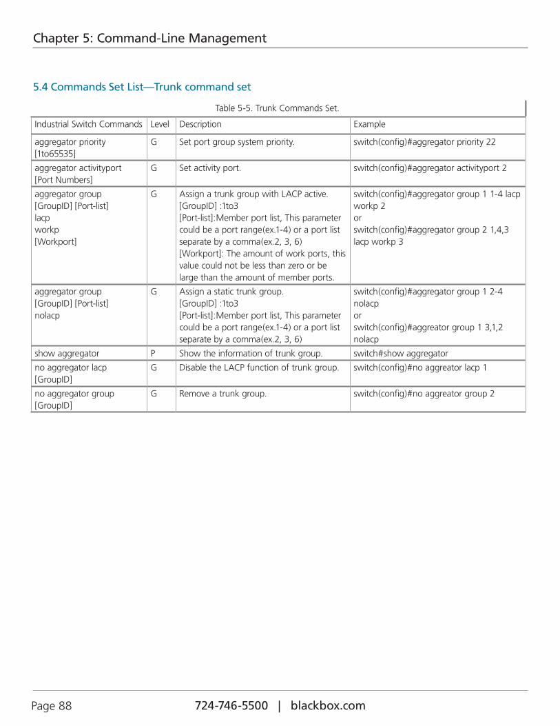
724-746-5500 | blackbox.com Page 88
Chapter 5: Command-Line Management
5.4 Commands Set List—Trunk command set
Table 5-5. Trunk Commands Set.
Industrial Switch Commands Level Description Example
aggregator priority [1to65535]
G Set port group system priority. switch(config)#aggregator priority 22
aggregator activityport [Port Numbers]
G Set activity port. switch(config)#aggregator activityport 2
aggregator group [GroupID] [Port-list] lacp workp [Workport]
G Assign a trunk group with LACP active. [GroupID] :1to3 [Port-list]:Member port list, This parameter could be a port range(ex.1-4) or a port list separate by a comma(ex.2, 3, 6) [Workport]: The amount of work ports, this value could not be less than zero or be large than the amount of member ports.
switch(config)#aggregator group 1 1-4 lacp workp 2 or switch(config)#aggregator group 2 1,4,3 lacp workp 3
aggregator group [GroupID] [Port-list] nolacp
G Assign a static trunk group. [GroupID] :1to3 [Port-list]:Member port list, This parameter could be a port range(ex.1-4) or a port list separate by a comma(ex.2, 3, 6)
switch(config)#aggregator group 1 2-4 nolacp or switch(config)#aggreator group 1 3,1,2 nolacp
show aggregator P Show the information of trunk group. switch#show aggregator
no aggregator lacp [GroupID]
G Disable the LACP function of trunk group. switch(config)#no aggreator lacp 1
no aggregator group [GroupID]
G Remove a trunk group. switch(config)#no aggreator group 2
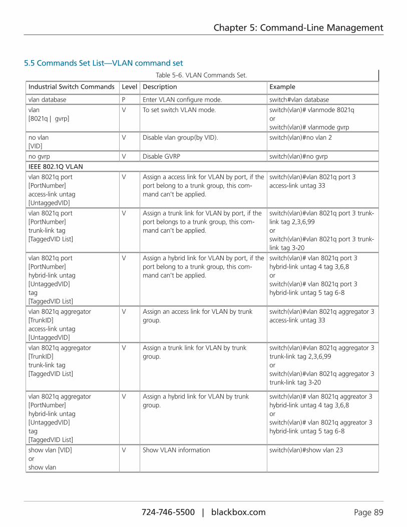
724-746-5500 | blackbox.com Page 89
Chapter 5: Command-Line Management
5.5 Commands Set List—VLAN command setTable 5-6. VLAN Commands Set.
Industrial Switch Commands Level Description Example
vlan database P Enter VLAN configure mode. switch#vlan database
vlan [8021q | gvrp]
V To set switch VLAN mode. switch(vlan)# vlanmode 8021q or switch(vlan)# vlanmode gvrp
no vlan [VID]
V Disable vlan group(by VID). switch(vlan)#no vlan 2
no gvrp V Disable GVRP switch(vlan)#no gvrp
IEEE 802.1Q VLAN
vlan 8021q port [PortNumber] access-link untag [UntaggedVID]
V Assign a access link for VLAN by port, if the port belong to a trunk group, this com-mand can’t be applied.
switch(vlan)#vlan 8021q port 3 access-link untag 33
vlan 8021q port [PortNumber] trunk-link tag [TaggedVID List]
V Assign a trunk link for VLAN by port, if the port belongs to a trunk group, this com-mand can’t be applied.
switch(vlan)#vlan 8021q port 3 trunk-link tag 2,3,6,99 or switch(vlan)#vlan 8021q port 3 trunk-link tag 3-20
vlan 8021q port [PortNumber] hybrid-link untag [UntaggedVID] tag [TaggedVID List]
V Assign a hybrid link for VLAN by port, if the port belong to a trunk group, this com-mand can’t be applied.
switch(vlan)# vlan 8021q port 3 hybrid-link untag 4 tag 3,6,8 or switch(vlan)# vlan 8021q port 3 hybrid-link untag 5 tag 6-8
vlan 8021q aggregator [TrunkID] access-link untag [UntaggedVID]
V Assign an access link for VLAN by trunk group.
switch(vlan)#vlan 8021q aggregator 3 access-link untag 33
vlan 8021q aggregator [TrunkID] trunk-link tag [TaggedVID List]
V Assign a trunk link for VLAN by trunk group.
switch(vlan)#vlan 8021q aggregator 3 trunk-link tag 2,3,6,99 or switch(vlan)#vlan 8021q aggregator 3 trunk-link tag 3-20
vlan 8021q aggregator [PortNumber] hybrid-link untag [UntaggedVID] tag [TaggedVID List]
V Assign a hybrid link for VLAN by trunk group.
switch(vlan)# vlan 8021q aggreator 3 hybrid-link untag 4 tag 3,6,8 or switch(vlan)# vlan 8021q aggreator 3 hybrid-link untag 5 tag 6-8
show vlan [VID] or show vlan
V Show VLAN information switch(vlan)#show vlan 23
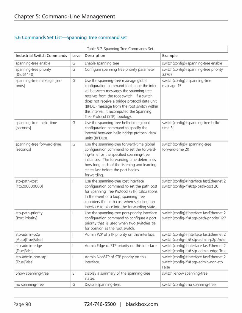
724-746-5500 | blackbox.com Page 90
Chapter 5: Command-Line Management
5.6 Commands Set List—Spanning Tree command set
Table 5-7. Spanning Tree Commands Set.
Industrial Switch Commands Level Description Example
spanning-tree enable G Enable spanning tree switch(config)#spanning-tree enable
spanning-tree priority [0to61440]
G Configure spanning tree priority parameter switch(config)#spanning-tree priority 32767
spanning-tree max-age [sec-onds]
G Use the spanning-tree max-age global configuration command to change the inter-val between messages the spanning tree receives from the root switch. If a switch does not receive a bridge protocol data unit (BPDU) message from the root switch within this interval, it recomputed the Spanning Tree Protocol (STP) topology.
switch(config)# spanning-tree max-age 15
spanning-tree hello-time [seconds]
G Use the spanning-tree hello-time global configuration command to specify the interval between hello bridge protocol data units (BPDUs).
switch(config)#spanning-tree hello-time 3
spanning-tree forward-time [seconds]
G Use the spanning-tree forward-time global configuration command to set the forward-ing-time for the specified spanning-tree instances. The forwarding time determines how long each of the listening and learning states last before the port begins forwarding.
switch(config)# spanning-tree forward-time 20
stp-path-cost [1to200000000]
I Use the spanning-tree cost interface configuration command to set the path cost for Spanning Tree Protocol (STP) calculations. In the event of a loop, spanning tree considers the path cost when selecting an interface to place into the forwarding state.
switch(config)#interface fastEthernet 2 switch(config-if)#stp-path-cost 20
stp-path-priority [Port Priority]
I Use the spanning-tree port-priority interface configuration command to configure a port priority that is used when two switches tie for position as the root switch.
switch(config)#interface fastEthernet 2 switch(config-if)# stp-path-priority 127
stp-admin-p2p [Auto|True|False]
I Admin P2P of STP priority on this interface. switch(config)#interface fastEthernet 2 switch(config-if)# stp-admin-p2p Auto
stp-admin-edge [True|False]
I Admin Edge of STP priority on this interface. switch(config)#interface fastEthernet 2 switch(config-if)# stp-admin-edge True
stp-admin-non-stp [True|False]
I Admin NonSTP of STP priority on this interface.
switch(config)#interface fastEthernet 2 switch(config-if)# stp-admin-non-stp False
Show spanning-tree E Display a summary of the spanning-tree states.
switch>show spanning-tree
no spanning-tree G Disable spanning-tree. switch(config)#no spanning-tree
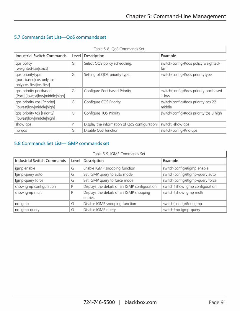
724-746-5500 | blackbox.com Page 91
Chapter 5: Command-Line Management
5.7 Commands Set List—QoS commands set
Table 5-8. QoS Commands Set.
Industrial Switch Commands Level Description Example
qos policy [weighted-fair|strict]
G Select QOS policy scheduling. switch(config)#qos policy weighted-fair
qos prioritytype [port-based|cos-only|tos-only|cos-first|tos-first]
G Setting of QOS priority type. switch(config)#qos prioritytype
qos priority portbased [Port] [lowest|low|middle|high]
G Configure Port-based Priority switch(config)#qos priority portbased 1 low
qos priority cos [Priority][lowest|low|middle|high]
G Configure COS Priority switch(config)#qos priority cos 22 middle
qos priority tos [Priority][lowest|low|middle|high]
G Configure TOS Priority switch(config)#qos priority tos 3 high
show qos P Display the information of QoS configuration switch>show qos
no qos G Disable QoS function switch(config)#no qos
5.8 Commands Set List—IGMP commands set
Table 5-9. IGMP Commands Set.
Industrial Switch Commands Level Description Example
igmp enable G Enable IGMP snooping function switch(config)#igmp enable
Igmp-query auto G Set IGMP query to auto mode switch(config)#Igmp-query auto
Igmp-query force G Set IGMP query to force mode switch(config)#Igmp-query force
show igmp configuration P Displays the details of an IGMP configuration. switch#show igmp configuration
show igmp multi P Displays the details of an IGMP snooping entries.
switch#show igmp multi
no igmp G Disable IGMP snooping function switch(config)#no igmp
no igmp-query G Disable IGMP query switch#no igmp-query
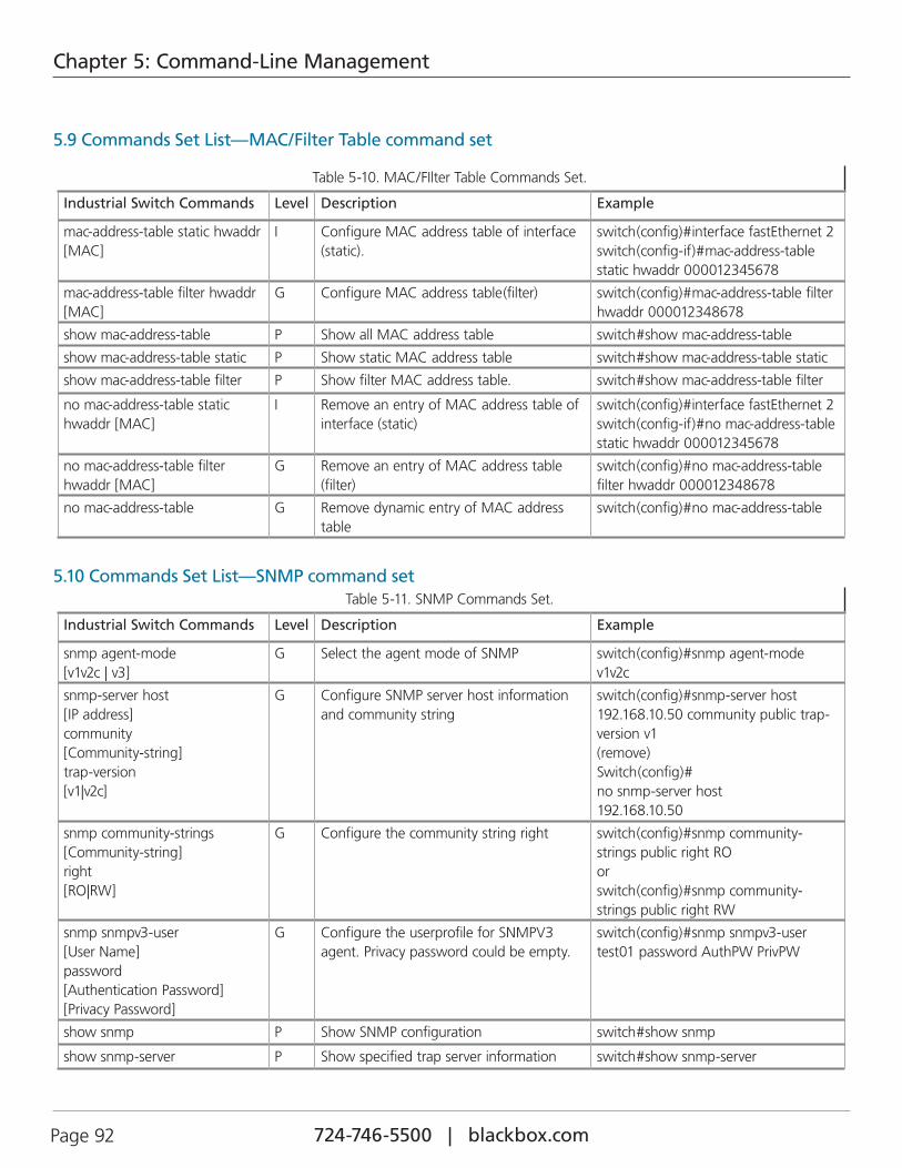
724-746-5500 | blackbox.com Page 92
Chapter 5: Command-Line Management
5.9 Commands Set List—MAC/Filter Table command set
Table 5-10. MAC/FIlter Table Commands Set.
Industrial Switch Commands Level Description Example
mac-address-table static hwaddr [MAC]
I Configure MAC address table of interface (static).
switch(config)#interface fastEthernet 2 switch(config-if)#mac-address-table static hwaddr 000012345678
mac-address-table filter hwaddr [MAC]
G Configure MAC address table(filter) switch(config)#mac-address-table filter hwaddr 000012348678
show mac-address-table P Show all MAC address table switch#show mac-address-table
show mac-address-table static P Show static MAC address table switch#show mac-address-table static
show mac-address-table filter P Show filter MAC address table. switch#show mac-address-table filter
no mac-address-table static hwaddr [MAC]
I Remove an entry of MAC address table of interface (static)
switch(config)#interface fastEthernet 2 switch(config-if)#no mac-address-table static hwaddr 000012345678
no mac-address-table filter hwaddr [MAC]
G Remove an entry of MAC address table (filter)
switch(config)#no mac-address-table filter hwaddr 000012348678
no mac-address-table G Remove dynamic entry of MAC address table
switch(config)#no mac-address-table
5.10 Commands Set List—SNMP command setTable 5-11. SNMP Commands Set.
Industrial Switch Commands Level Description Example
snmp agent-mode [v1v2c | v3]
G Select the agent mode of SNMP switch(config)#snmp agent-mode v1v2c
snmp-server host [IP address] community [Community-string] trap-version [v1|v2c]
G Configure SNMP server host information and community string
switch(config)#snmp-server host 192.168.10.50 community public trap-version v1 (remove) Switch(config)# no snmp-server host 192.168.10.50
snmp community-strings [Community-string] right [RO|RW]
G Configure the community string right switch(config)#snmp community-strings public right RO or switch(config)#snmp community-strings public right RW
snmp snmpv3-user [User Name] password [Authentication Password] [Privacy Password]
G Configure the userprofile for SNMPV3 agent. Privacy password could be empty.
switch(config)#snmp snmpv3-user test01 password AuthPW PrivPW
show snmp P Show SNMP configuration switch#show snmp
show snmp-server P Show specified trap server information switch#show snmp-server
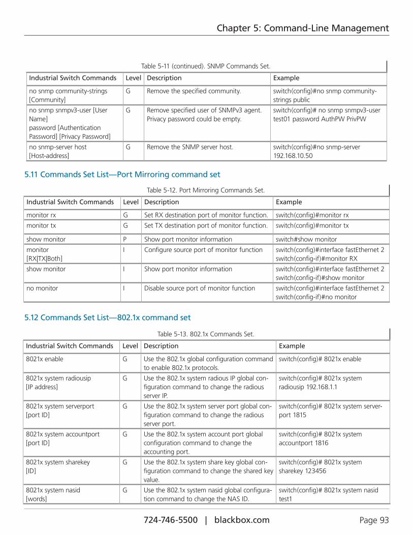
724-746-5500 | blackbox.com Page 93
Chapter 5: Command-Line Management
Table 5-11 (continued). SNMP Commands Set.
Industrial Switch Commands Level Description Example
no snmp community-strings [Community]
G Remove the specified community. switch(config)#no snmp community-strings public
no snmp snmpv3-user [User Name] password [Authentication Password] [Privacy Password]
G Remove specified user of SNMPv3 agent. Privacy password could be empty.
switch(config)# no snmp snmpv3-user test01 password AuthPW PrivPW
no snmp-server host [Host-address]
G Remove the SNMP server host. switch(config)#no snmp-server 192.168.10.50
5.11 Commands Set List—Port Mirroring command set
Table 5-12. Port Mirroring Commands Set.
Industrial Switch Commands Level Description Example
monitor rx G Set RX destination port of monitor function. switch(config)#monitor rx
monitor tx G Set TX destination port of monitor function. switch(config)#monitor tx
show monitor P Show port monitor information switch#show monitor
monitor [RX|TX|Both]
I Configure source port of monitor function switch(config)#interface fastEthernet 2 switch(config-if)#monitor RX
show monitor I Show port monitor information switch(config)#interface fastEthernet 2 switch(config-if)#show monitor
no monitor I Disable source port of monitor function switch(config)#interface fastEthernet 2 switch(config-if)#no monitor
5.12 Commands Set List—802.1x command set
Table 5-13. 802.1x Commands Set.
Industrial Switch Commands Level Description Example
8021x enable G Use the 802.1x global configuration command to enable 802.1x protocols.
switch(config)# 8021x enable
8021x system radiousip [IP address]
G Use the 802.1x system radious IP global con-figuration command to change the radious server IP.
switch(config)# 8021x system radiousip 192.168.1.1
8021x system serverport [port ID]
G Use the 802.1x system server port global con-figuration command to change the radious server port.
switch(config)# 8021x system server-port 1815
8021x system accountport [port ID]
G Use the 802.1x system account port global configuration command to change the accounting port.
switch(config)# 8021x system accountport 1816
8021x system sharekey [ID]
G Use the 802.1x system share key global con-figuration command to change the shared key value.
switch(config)# 8021x system sharekey 123456
8021x system nasid [words]
G Use the 802.1x system nasid global configura-tion command to change the NAS ID.
switch(config)# 8021x system nasid test1
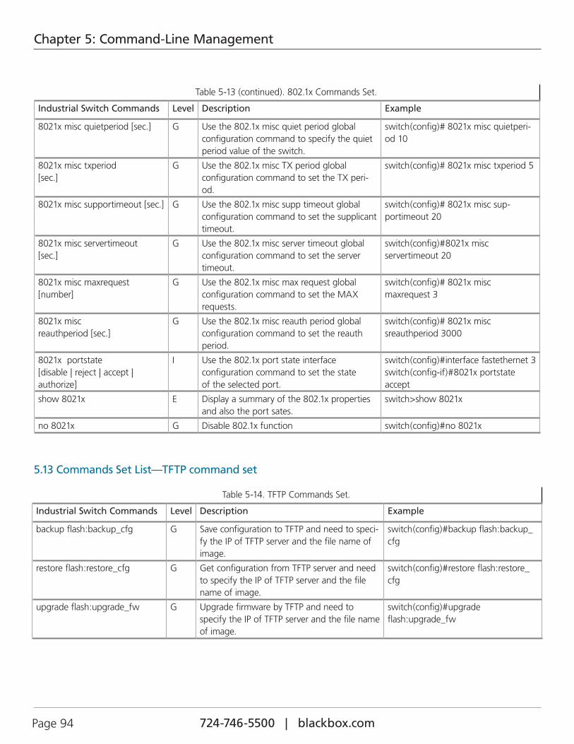
724-746-5500 | blackbox.com Page 94
Chapter 5: Command-Line Management
Table 5-13 (continued). 802.1x Commands Set.
Industrial Switch Commands Level Description Example
8021x misc quietperiod [sec.] G Use the 802.1x misc quiet period global configuration command to specify the quiet period value of the switch.
switch(config)# 8021x misc quietperi-od 10
8021x misc txperiod [sec.]
G Use the 802.1x misc TX period global configuration command to set the TX peri-od.
switch(config)# 8021x misc txperiod 5
8021x misc supportimeout [sec.] G Use the 802.1x misc supp timeout global configuration command to set the supplicant timeout.
switch(config)# 8021x misc sup-portimeout 20
8021x misc servertimeout [sec.]
G Use the 802.1x misc server timeout global configuration command to set the server timeout.
switch(config)#8021x misc servertimeout 20
8021x misc maxrequest [number]
G Use the 802.1x misc max request global configuration command to set the MAX requests.
switch(config)# 8021x misc maxrequest 3
8021x misc reauthperiod [sec.]
G Use the 802.1x misc reauth period global configuration command to set the reauth period.
switch(config)# 8021x misc sreauthperiod 3000
8021x portstate [disable | reject | accept | authorize]
I Use the 802.1x port state interface configuration command to set the state of the selected port.
switch(config)#interface fastethernet 3 switch(config-if)#8021x portstate accept
show 8021x E Display a summary of the 802.1x properties and also the port sates.
switch>show 8021x
no 8021x G Disable 802.1x function switch(config)#no 8021x
5.13 Commands Set List—TFTP command set
Table 5-14. TFTP Commands Set.
Industrial Switch Commands Level Description Example
backup flash:backup_cfg G Save configuration to TFTP and need to speci-fy the IP of TFTP server and the file name of image.
switch(config)#backup flash:backup_cfg
restore flash:restore_cfg G Get configuration from TFTP server and need to specify the IP of TFTP server and the file name of image.
switch(config)#restore flash:restore_cfg
upgrade flash:upgrade_fw G Upgrade firmware by TFTP and need to specify the IP of TFTP server and the file name of image.
switch(config)#upgrade flash:upgrade_fw
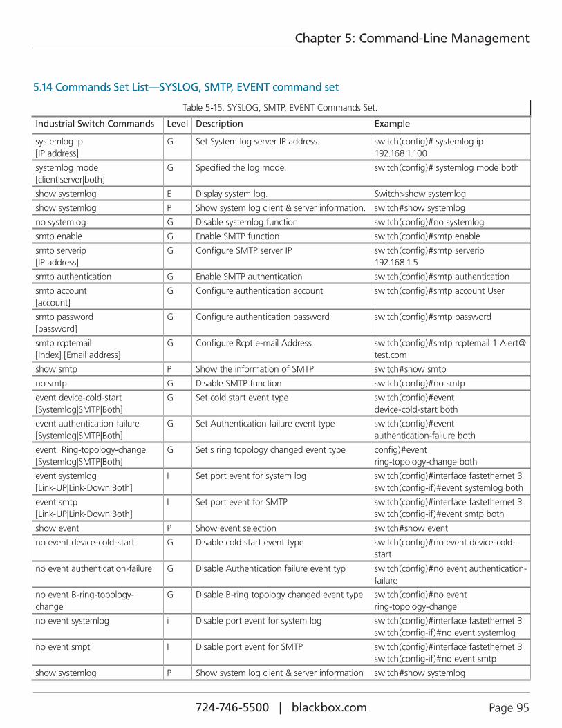
724-746-5500 | blackbox.com Page 95
Chapter 5: Command-Line Management
5.14 Commands Set List—SYSLOG, SMTP, EVENT command set
Table 5-15. SYSLOG, SMTP, EVENT Commands Set.
Industrial Switch Commands Level Description Example
systemlog ip [IP address]
G Set System log server IP address. switch(config)# systemlog ip 192.168.1.100
systemlog mode [client|server|both]
G Specified the log mode. switch(config)# systemlog mode both
show systemlog E Display system log. Switch>show systemlog
show systemlog P Show system log client & server information. switch#show systemlog
no systemlog G Disable systemlog function switch(config)#no systemlog
smtp enable G Enable SMTP function switch(config)#smtp enable
smtp serverip [IP address]
G Configure SMTP server IP switch(config)#smtp serverip 192.168.1.5
smtp authentication G Enable SMTP authentication switch(config)#smtp authentication
smtp account [account]
G Configure authentication account switch(config)#smtp account User
smtp password [password]
G Configure authentication password switch(config)#smtp password
smtp rcptemail [Index] [Email address]
G Configure Rcpt e-mail Address switch(config)#smtp rcptemail 1 [email protected]
show smtp P Show the information of SMTP switch#show smtp
no smtp G Disable SMTP function switch(config)#no smtp
event device-cold-start [Systemlog|SMTP|Both]
G Set cold start event type switch(config)#event device-cold-start both
event authentication-failure [Systemlog|SMTP|Both]
G Set Authentication failure event type switch(config)#event authentication-failure both
event Ring-topology-change [Systemlog|SMTP|Both]
G Set s ring topology changed event type config)#event ring-topology-change both
event systemlog [Link-UP|Link-Down|Both]
I Set port event for system log switch(config)#interface fastethernet 3 switch(config-if)#event systemlog both
event smtp [Link-UP|Link-Down|Both]
I Set port event for SMTP switch(config)#interface fastethernet 3 switch(config-if)#event smtp both
show event P Show event selection switch#show event
no event device-cold-start G Disable cold start event type switch(config)#no event device-cold-start
no event authentication-failure G Disable Authentication failure event typ switch(config)#no event authentication-failure
no event B-ring-topology-change
G Disable B-ring topology changed event type switch(config)#no event ring-topology-change
no event systemlog i Disable port event for system log switch(config)#interface fastethernet 3 switch(config-if)#no event systemlog
no event smpt I Disable port event for SMTP switch(config)#interface fastethernet 3 switch(config-if)#no event smtp
show systemlog P Show system log client & server information switch#show systemlog
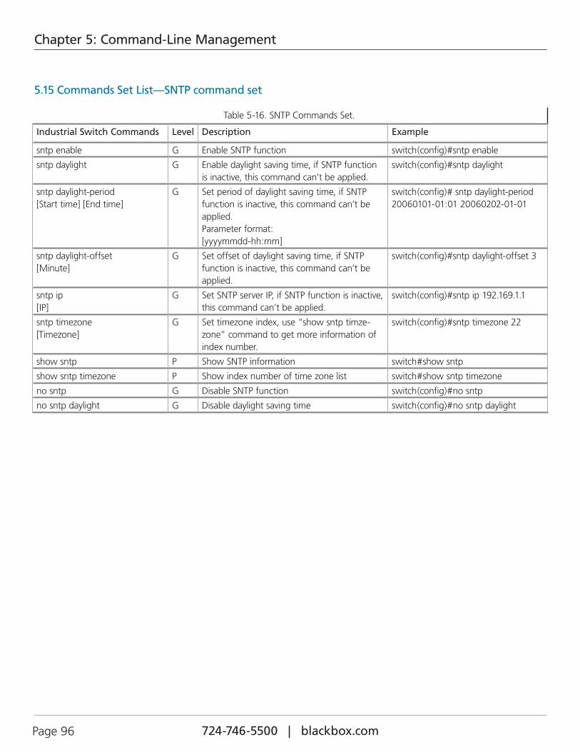
724-746-5500 | blackbox.com Page 96
Chapter 5: Command-Line Management
5.15 Commands Set List—SNTP command set
Table 5-16. SNTP Commands Set.
Industrial Switch Commands Level Description Example
sntp enable G Enable SNTP function switch(config)#sntp enable
sntp daylight G Enable daylight saving time, if SNTP function is inactive, this command can’t be applied.
switch(config)#sntp daylight
sntp daylight-period [Start time] [End time]
G Set period of daylight saving time, if SNTP function is inactive, this command can’t be applied. Parameter format: [yyyymmdd-hh:mm]
switch(config)# sntp daylight-period 20060101-01:01 20060202-01-01
sntp daylight-offset [Minute]
G Set offset of daylight saving time, if SNTP function is inactive, this command can’t be applied.
switch(config)#sntp daylight-offset 3
sntp ip [IP]
G Set SNTP server IP, if SNTP function is inactive, this command can’t be applied.
switch(config)#sntp ip 192.169.1.1
sntp timezone [Timezone]
G Set timezone index, use “show sntp timze-zone” command to get more information of index number.
switch(config)#sntp timezone 22
show sntp P Show SNTP information switch#show sntp
show sntp timezone P Show index number of time zone list switch#show sntp timezone
no sntp G Disable SNTP function switch(config)#no sntp
no sntp daylight G Disable daylight saving time switch(config)#no sntp daylight
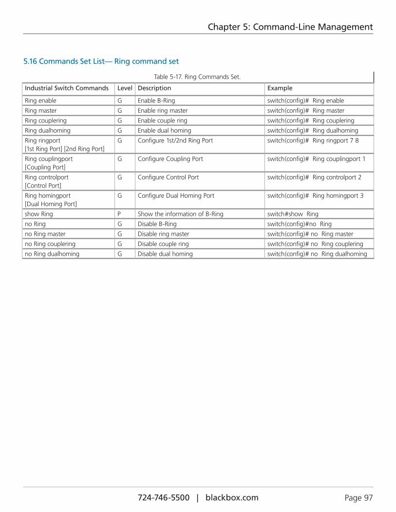
724-746-5500 | blackbox.com Page 97
Chapter 5: Command-Line Management
5.16 Commands Set List— Ring command set
Table 5-17. Ring Commands Set.
Industrial Switch Commands Level Description Example
Ring enable G Enable B-Ring switch(config)# Ring enable
Ring master G Enable ring master switch(config)# Ring master
Ring couplering G Enable couple ring switch(config)# Ring couplering
Ring dualhoming G Enable dual homing switch(config)# Ring dualhoming
Ring ringport [1st Ring Port] [2nd Ring Port]
G Configure 1st/2nd Ring Port switch(config)# Ring ringport 7 8
Ring couplingport [Coupling Port]
G Configure Coupling Port switch(config)# Ring couplingport 1
Ring controlport [Control Port]
G Configure Control Port switch(config)# Ring controlport 2
Ring homingport [Dual Homing Port]
G Configure Dual Homing Port switch(config)# Ring homingport 3
show Ring P Show the information of B-Ring switch#show Ring
no Ring G Disable B-Ring switch(config)#no Ring
no Ring master G Disable ring master switch(config)# no Ring master
no Ring couplering G Disable couple ring switch(config)# no Ring couplering
no Ring dualhoming G Disable dual homing switch(config)# no Ring dualhoming
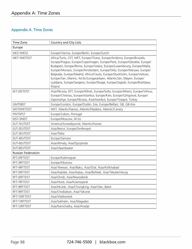
724-746-5500 | blackbox.com Page 98
Appendix A: Time Zones
Appendix A. Time Zones
Time Zone Country and City Lists
Europe
MEZ-1MESZ Europe/Vienna, Europe/Berlin, Europe/Zurich
MET-1METDST Africa/Tunis, CET, MET, Europe/Tirane, Europe/Andorra, Europe/Brussels, Europe/Prague, Europe/Copenhagen, Europe/Paris, Europe/Gibraltar, Europe/Budapest, Europe/Rome, Europe/Vaduz, Europe/Luxembourg, Europe/Malta, Europe/Monaco, Europe/Amsterdam, Europe/Oslo, Europe/Warsaw, Europe/Belgrade, Europe/Madrid, Africa/Ceuta, Europe/Stockholm, Europe/Vatican, Europe/San_Marino, Arctic/Longyearbyen, Atlantic/Jan_Mayen, Europe/Ljubljana, Europe/Sarajevo, Europe/Skopje, Europe/Zagreb, Europe/Bratislava, Poland
EET-2EETDST Asia/Nicosia, EET, Europe/Minsk, Europe/Sofia, Europe/Athens, Europe/Vilnius, Europe/Chisinau, Europe/Istanbul, Europe/Kiev, Europe/Uzhgorod, Europe/Zaporozhye, Europe/Nicosia, Asia/Istanbul, Europe/Tiraspol, Turkey
GMT0BST Europe/London, Europe/Dublin, Eire, Europe/Belfast, GB, GB-Eire
WET0WETDST WET, Atlantic/Faeroe, Atlantic/Madeira, Atlantic/Canary
PWT0PST Europe/Lisbon, Portugal
MST-3MDT Europe/Moscow, W-SU
EUT-1EUTDST America/Scoresbysund, Atlantic/Azores
EUT-2EUTDST Asia/Beirut, Europe/Simferopol
EUT-3EUTDST Asia/Tbilisi
EUT-4EUTDST Europe/Samara
EUT-6EUTDST Asia/Almaty, Asia/Qyzylorda
EUT-8EUTDST Asia/Ulaanbaatar
Russian Federation
RFT-2RFTDST Europe/Kaliningrad
RFT-3RFTDST Europe/Moscow
RFT-4RFTDST Asia/Yerevan, Asia/Baku, Asia/Oral, Asia/Ashkhabad
RFT-5RFTDST Asia/Aqtobe, Asia/Aqtau, Asia/Bishkek, Asia/Yekaterinburg
RFT-6RFTDST Asia/Omsk, Asia/Novosibirsk
RFT-7RFTDST Asia/Hovd, Asia/Krasnoyarsk
RFT-8RFTDST Asia/Irkutsk, Asia/Chungking, Asia/Ulan_Bator
RFT-9RFTDST Asia/Choibalsan, Asia/Yakutsk
RFT-10RFTDST Asia/Vladivostok
RFT-11RFTDST Asia/Sakhalin, Asia/Magadan
RFT-12RFTDST Asia/Kamchatka, Asia/Anadyr
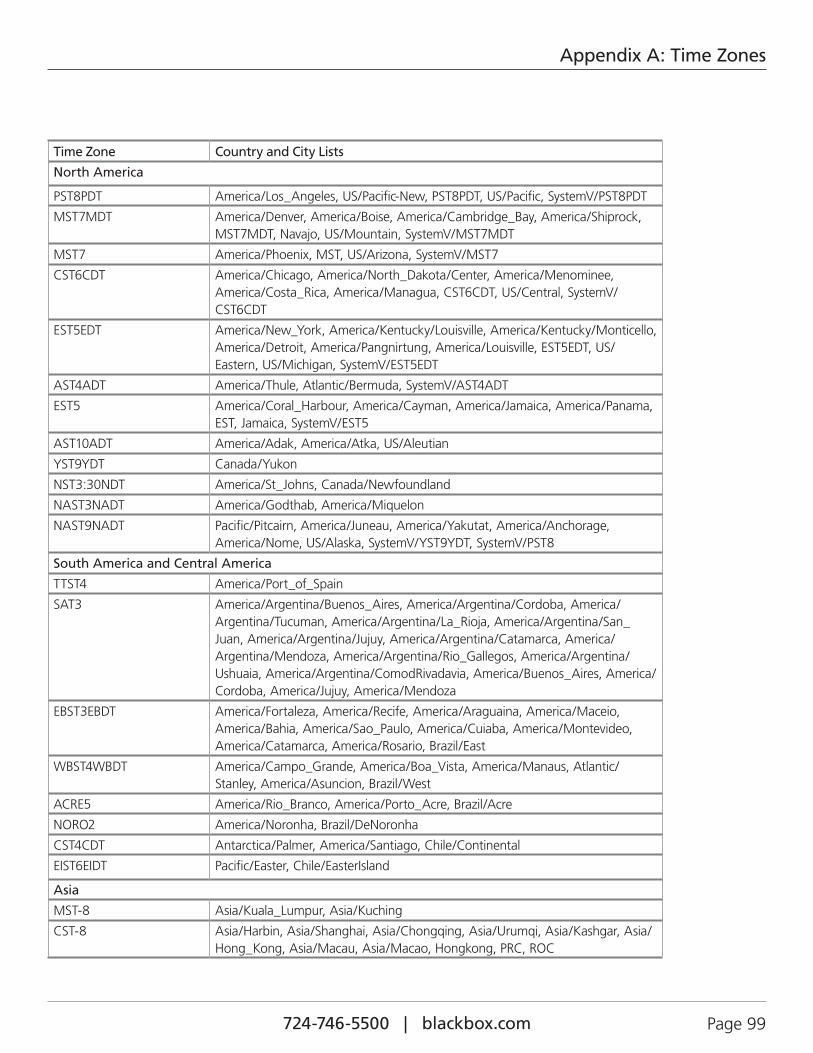
724-746-5500 | blackbox.com Page 99
Appendix A: Time Zones
Time Zone Country and City Lists
North America
PST8PDT America/Los_Angeles, US/Pacific-New, PST8PDT, US/Pacific, SystemV/PST8PDT
MST7MDT America/Denver, America/Boise, America/Cambridge_Bay, America/Shiprock, MST7MDT, Navajo, US/Mountain, SystemV/MST7MDT
MST7 America/Phoenix, MST, US/Arizona, SystemV/MST7
CST6CDT America/Chicago, America/North_Dakota/Center, America/Menominee, America/Costa_Rica, America/Managua, CST6CDT, US/Central, SystemV/CST6CDT
EST5EDT America/New_York, America/Kentucky/Louisville, America/Kentucky/Monticello, America/Detroit, America/Pangnirtung, America/Louisville, EST5EDT, US/Eastern, US/Michigan, SystemV/EST5EDT
AST4ADT America/Thule, Atlantic/Bermuda, SystemV/AST4ADT
EST5 America/Coral_Harbour, America/Cayman, America/Jamaica, America/Panama, EST, Jamaica, SystemV/EST5
AST10ADT America/Adak, America/Atka, US/Aleutian
YST9YDT Canada/Yukon
NST3:30NDT America/St_Johns, Canada/Newfoundland
NAST3NADT America/Godthab, America/Miquelon
NAST9NADT Pacific/Pitcairn, America/Juneau, America/Yakutat, America/Anchorage, America/Nome, US/Alaska, SystemV/YST9YDT, SystemV/PST8
South America and Central America
TTST4 America/Port_of_Spain
SAT3 America/Argentina/Buenos_Aires, America/Argentina/Cordoba, America/Argentina/Tucuman, America/Argentina/La_Rioja, America/Argentina/San_Juan, America/Argentina/Jujuy, America/Argentina/Catamarca, America/Argentina/Mendoza, America/Argentina/Rio_Gallegos, America/Argentina/Ushuaia, America/Argentina/ComodRivadavia, America/Buenos_Aires, America/Cordoba, America/Jujuy, America/Mendoza
EBST3EBDT America/Fortaleza, America/Recife, America/Araguaina, America/Maceio, America/Bahia, America/Sao_Paulo, America/Cuiaba, America/Montevideo, America/Catamarca, America/Rosario, Brazil/East
WBST4WBDT America/Campo_Grande, America/Boa_Vista, America/Manaus, Atlantic/Stanley, America/Asuncion, Brazil/West
ACRE5 America/Rio_Branco, America/Porto_Acre, Brazil/Acre
NORO2 America/Noronha, Brazil/DeNoronha
CST4CDT Antarctica/Palmer, America/Santiago, Chile/Continental
EIST6EIDT Pacific/Easter, Chile/EasterIsland
Asia
MST-8 Asia/Kuala_Lumpur, Asia/Kuching
CST-8 Asia/Harbin, Asia/Shanghai, Asia/Chongqing, Asia/Urumqi, Asia/Kashgar, Asia/Hong_Kong, Asia/Macau, Asia/Macao, Hongkong, PRC, ROC
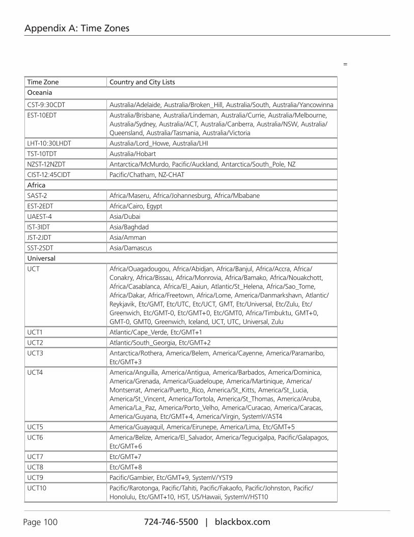
724-746-5500 | blackbox.com Page 100
Appendix A: Time Zones
Time Zone Country and City Lists
Oceania
CST-9:30CDT Australia/Adelaide, Australia/Broken_Hill, Australia/South, Australia/Yancowinna
EST-10EDT Australia/Brisbane, Australia/Lindeman, Australia/Currie, Australia/Melbourne, Australia/Sydney, Australia/ACT, Australia/Canberra, Australia/NSW, Australia/Queensland, Australia/Tasmania, Australia/Victoria
LHT-10:30LHDT Australia/Lord_Howe, Australia/LHI
TST-10TDT Australia/Hobart
NZST-12NZDT Antarctica/McMurdo, Pacific/Auckland, Antarctica/South_Pole, NZ
CIST-12:45CIDT Pacific/Chatham, NZ-CHAT
Africa
SAST-2 Africa/Maseru, Africa/Johannesburg, Africa/Mbabane
EST-2EDT Africa/Cairo, Egypt
UAEST-4 Asia/Dubai
IST-3IDT Asia/Baghdad
JST-2JDT Asia/Amman
SST-2SDT Asia/Damascus
Universal
UCT Africa/Ouagadougou, Africa/Abidjan, Africa/Banjul, Africa/Accra, Africa/Conakry, Africa/Bissau, Africa/Monrovia, Africa/Bamako, Africa/Nouakchott, Africa/Casablanca, Africa/El_Aaiun, Atlantic/St_Helena, Africa/Sao_Tome, Africa/Dakar, Africa/Freetown, Africa/Lome, America/Danmarkshavn, Atlantic/Reykjavik, Etc/GMT, Etc/UTC, Etc/UCT, GMT, Etc/Universal, Etc/Zulu, Etc/Greenwich, Etc/GMT-0, Etc/GMT+0, Etc/GMT0, Africa/Timbuktu, GMT+0, GMT-0, GMT0, Greenwich, Iceland, UCT, UTC, Universal, Zulu
UCT1 Atlantic/Cape_Verde, Etc/GMT+1
UCT2 Atlantic/South_Georgia, Etc/GMT+2
UCT3 Antarctica/Rothera, America/Belem, America/Cayenne, America/Paramaribo, Etc/GMT+3
UCT4 America/Anguilla, America/Antigua, America/Barbados, America/Dominica, America/Grenada, America/Guadeloupe, America/Martinique, America/Montserrat, America/Puerto_Rico, America/St_Kitts, America/St_Lucia, America/St_Vincent, America/Tortola, America/St_Thomas, America/Aruba, America/La_Paz, America/Porto_Velho, America/Curacao, America/Caracas, America/Guyana, Etc/GMT+4, America/Virgin, SystemV/AST4
UCT5 America/Guayaquil, America/Eirunepe, America/Lima, Etc/GMT+5
UCT6 America/Belize, America/El_Salvador, America/Tegucigalpa, Pacific/Galapagos, Etc/GMT+6
UCT7 Etc/GMT+7
UCT8 Etc/GMT+8
UCT9 Pacific/Gambier, Etc/GMT+9, SystemV/YST9
UCT10 Pacific/Rarotonga, Pacific/Tahiti, Pacific/Fakaofo, Pacific/Johnston, Pacific/Honolulu, Etc/GMT+10, HST, US/Hawaii, SystemV/HST10
=
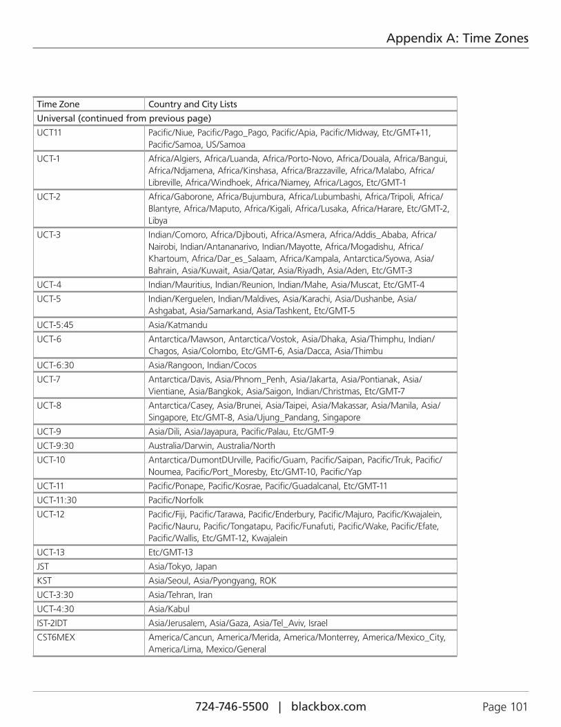
724-746-5500 | blackbox.com Page 101
Appendix A: Time Zones
Time Zone Country and City Lists
Universal (continued from previous page)
UCT11 Pacific/Niue, Pacific/Pago_Pago, Pacific/Apia, Pacific/Midway, Etc/GMT+11, Pacific/Samoa, US/Samoa
UCT-1 Africa/Algiers, Africa/Luanda, Africa/Porto-Novo, Africa/Douala, Africa/Bangui, Africa/Ndjamena, Africa/Kinshasa, Africa/Brazzaville, Africa/Malabo, Africa/Libreville, Africa/Windhoek, Africa/Niamey, Africa/Lagos, Etc/GMT-1
UCT-2 Africa/Gaborone, Africa/Bujumbura, Africa/Lubumbashi, Africa/Tripoli, Africa/Blantyre, Africa/Maputo, Africa/Kigali, Africa/Lusaka, Africa/Harare, Etc/GMT-2, Libya
UCT-3 Indian/Comoro, Africa/Djibouti, Africa/Asmera, Africa/Addis_Ababa, Africa/Nairobi, Indian/Antananarivo, Indian/Mayotte, Africa/Mogadishu, Africa/Khartoum, Africa/Dar_es_Salaam, Africa/Kampala, Antarctica/Syowa, Asia/Bahrain, Asia/Kuwait, Asia/Qatar, Asia/Riyadh, Asia/Aden, Etc/GMT-3
UCT-4 Indian/Mauritius, Indian/Reunion, Indian/Mahe, Asia/Muscat, Etc/GMT-4
UCT-5 Indian/Kerguelen, Indian/Maldives, Asia/Karachi, Asia/Dushanbe, Asia/Ashgabat, Asia/Samarkand, Asia/Tashkent, Etc/GMT-5
UCT-5:45 Asia/Katmandu
UCT-6 Antarctica/Mawson, Antarctica/Vostok, Asia/Dhaka, Asia/Thimphu, Indian/Chagos, Asia/Colombo, Etc/GMT-6, Asia/Dacca, Asia/Thimbu
UCT-6:30 Asia/Rangoon, Indian/Cocos
UCT-7 Antarctica/Davis, Asia/Phnom_Penh, Asia/Jakarta, Asia/Pontianak, Asia/Vientiane, Asia/Bangkok, Asia/Saigon, Indian/Christmas, Etc/GMT-7
UCT-8 Antarctica/Casey, Asia/Brunei, Asia/Taipei, Asia/Makassar, Asia/Manila, Asia/Singapore, Etc/GMT-8, Asia/Ujung_Pandang, Singapore
UCT-9 Asia/Dili, Asia/Jayapura, Pacific/Palau, Etc/GMT-9
UCT-9:30 Australia/Darwin, Australia/North
UCT-10 Antarctica/DumontDUrville, Pacific/Guam, Pacific/Saipan, Pacific/Truk, Pacific/Noumea, Pacific/Port_Moresby, Etc/GMT-10, Pacific/Yap
UCT-11 Pacific/Ponape, Pacific/Kosrae, Pacific/Guadalcanal, Etc/GMT-11
UCT-11:30 Pacific/Norfolk
UCT-12 Pacific/Fiji, Pacific/Tarawa, Pacific/Enderbury, Pacific/Majuro, Pacific/Kwajalein, Pacific/Nauru, Pacific/Tongatapu, Pacific/Funafuti, Pacific/Wake, Pacific/Efate, Pacific/Wallis, Etc/GMT-12, Kwajalein
UCT-13 Etc/GMT-13
JST Asia/Tokyo, Japan
KST Asia/Seoul, Asia/Pyongyang, ROK
UCT-3:30 Asia/Tehran, Iran
UCT-4:30 Asia/Kabul
IST-2IDT Asia/Jerusalem, Asia/Gaza, Asia/Tel_Aviv, Israel
CST6MEX America/Cancun, America/Merida, America/Monterrey, America/Mexico_City, America/Lima, Mexico/General
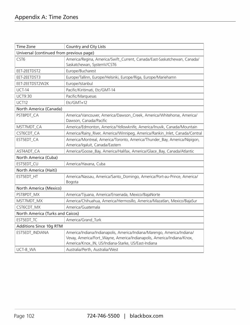
724-746-5500 | blackbox.com Page 102
Appendix A: Time Zones
Time Zone Country and City Lists
Universal (continued from previous page)
CST6 America/Regina, America/Swift_Current, Canada/East-Saskatchewan, Canada/Saskatchewan, SystemV/CST6
EET-2EETDST2 Europe/Bucharest
EET-2EETDST3 Europe/Tallinn, Europe/Helsinki, Europe/Riga, Europe/Mariehamn
EET-2EETDST2W2K Europe/Istanbul
UCT-14 Pacific/Kiritimati, Etc/GMT-14
UCT9:30 Pacific/Marquesas
UCT12 Etc/GMT+12
North America (Canada)
PST8PDT_CA America/Vancouver, America/Dawson_Creek, America/Whitehorse, America/Dawson, Canada/Pacific
MST7MDT_CA America/Edmonton, America/Yellowknife, America/Inuvik, Canada/Mountain
CST6CDT_CA America/Rainy_River, America/Winnipeg, America/Rankin_Inlet, Canada/Central
EST5EDT_CA America/Montreal, America/Toronto, America/Thunder_Bay, America/Nipigon, America/Iqaluit, Canada/Eastern
AST4ADT_CA America/Goose_Bay, America/Halifax, America/Glace_Bay, Canada/Atlantic
North America (Cuba)
EST5EDT_CU America/Havana, Cuba
North America (Haiti)
EST5EDT_HT America/Nassau, America/Santo_Domingo, America/Port-au-Prince, America/Bogota
North America (Mexico)
PST8PDT_MX America/Tijuana, America/Ensenada, Mexico/BajaNorte
MST7MDT_MX America/Chihuahua, America/Hermosillo, America/Mazatlan, Mexico/BajaSur
CST6CDT_MX America/Guatemala
North America (Turks and Caicos)
EST5EDT_TC America/Grand_Turk
Additions Since 10g RTM
EST5EDT_INDIANA America/Indiana/Indianapolis, America/Indiana/Marengo, America/Indiana/Vevay, America/Fort_Wayne, America/Indianapolis, America/Indiana/Knox, America/Knox_IN, US/Indiana-Starke, US/East-Indiana
UCT-8_WA Australia/Perth, Australia/West

724-746-5500 | blackbox.com Page 103
NOTES

724-746-5500 | blackbox.com
About Black BoxBlack Box provides an extensive range of networking and infrastructure products. You’ll find everything from cabinets and racks and power and surge protection products to media converters and Ethernet switches all supported by free, live 24/7 Tech support available in 60 seconds or less.
© Copyright 2015. Black Box Corporation. All rights reserved. Black Box® and the Double Diamond logo are registered trademarks of BB Technologies, Inc. Any third-party trademarks appearing in this manual are acknowledged to be the property of their respective owners.
Black Box Tech Support: FREE! Live. 24/7.
Tech support the way it should be.
Great tech support is just 60 seconds away at 724-746-5500 or blackbox.com.
LEH2004A-4GSFP User Manual, version 1


![[PPT]Fast Ethernet and Gigabit Ethernet - WPIweb.cs.wpi.edu/~rek/Undergrad_Nets/B04/Fast_Ethernet.ppt · Web viewFast Ethernet and Gigabit Ethernet Fast Ethernet (100BASE-T) How to](https://img.pdfslide.net/doc/110x75/5b29d4a97f8b9aad2f8b4e9d/pptfast-ethernet-and-gigabit-ethernet-rekundergradnetsb04fastethernetppt.jpg)