Embed Size (px)
Citation preview
Industrial refrigeration equipmentA guide to equipment eligible for Enhanced Capital Allowances
Technology information leaflet ECA768
Contents
Introduction 01
Background 01
Setting the scene 01
Benefits of purchasing ETL-listed products 02
Industrial refrigeration equipment eligible under the ECA scheme 02
Absorption coolers 03
Air-cooled condensing units 03
Automatic leak detection 04
Automatic air purgers 05
Refrigeration system controls 05
Evaporative condensers 05
Liquid pressure amplification 06
Packaged chillers 07
Refrigeration compressors 08
Calculating the payback of your investment 09
01Industrial refrigeration equipment
1 Eligibility for ECAs is based on a number of factors. Visit www.eca.gov.uk/energy to find out more.2 Food and Drink Industry Refrigeration Initiative, Guide 2, Purchase of efficient refrigeration plant, IOR, July 2007.
IntroductionECAs are a straightforward way for a business to improve its cash flow through accelerated tax relief. The scheme encourages businesses to invest in energy saving plant or machinery specified in the ETL to help reduce carbon emissions which contribute to climate change.
The Energy Technology List (ETL) is a register of products that may be eligible for 100% tax relief under the Enhanced Capital Allowance (ECA) scheme for energy saving technologies1. The Carbon Trust manages the list and promotes the ECA scheme on behalf of Government.
This leaflet gives an overview of industrial refrigeration equipment specified on the ETL and aims to help businesses present a sound business case for purchasing energy saving equipment from ETL manufacturers and suppliers.
Background The ETL comprises two lists: the Energy Technology Criteria List (ETCL) and the Energy Technology Product List (ETPL). The ETCL defines the performance criteria that equipment must meet to qualify for ECA scheme support; whereas the ETPL is a qualified list of products that have been assessed as being compliant with ETCL criteria.
Setting the sceneThere are two primary applications of industrial refrigeration equipment:
• Cooling, freezing and temperature maintenance during storage, transportation and distribution of food products.
• Air conditioning systems.
Other applications of industrial refrigeration can be found in chemical plant (for example, for the separation of gases), in manufacturing and construction, in ice and snow sports and in environmental test chambers.
Industrial refrigeration systems use large amounts of energy and typically cost 7-10 times as much to run over their lifetime as they do to buy2. The use of energy efficient industrial refrigeration equipment, such as that listed on the ETL, can result in significant energy savings and, therefore, reduced energy bills.
Further information
For more information visit www.carbontrust.co.uk/refrigeration or download the Carbon Trust’s Refrigeration technology overview (CTV002).
02 The Carbon Trust
Benefits of purchasing ETL-listed products A system using an ETL-listed industrial refrigeration product can use significantly less energy than a typical system using non-ETL products. ETL-listed products have a number of energy efficiency advantages, including higher efficiencies of specific components such as compressors; better combinations of components in packaged chillers and condensing units; the use of free cooling; improved controls; and better operation achieved through the use of refrigerant leak detection and automated air purgers.
When replacing equipment, businesses are often tempted to opt for that with the lowest capital cost; however, such immediate cost savings can prove to be a false economy. Considering the life cycle cost before investing in equipment can help reduce costs and improve cash flow in the longer term.
The ECA scheme provides businesses with 100% first year tax relief on their qualifying capital expenditure. This means that businesses can write off the whole cost of the equipment against taxable profits in the year of purchase. This can provide a cash flow boost and an incentive to invest in energy saving equipment which normally carries a price premium when compared to less efficient alternatives.
Using this leaflet you can calculate the benefits of investing in qualifying ETL energy saving equipment over non qualifying equipment. The calculation includes the benefits of accelerated tax relief, reduced running costs, increased efficiency, lower energy bills and reduced Climate Change Levy payments (if applicable), which in turn helps reduce payback periods.
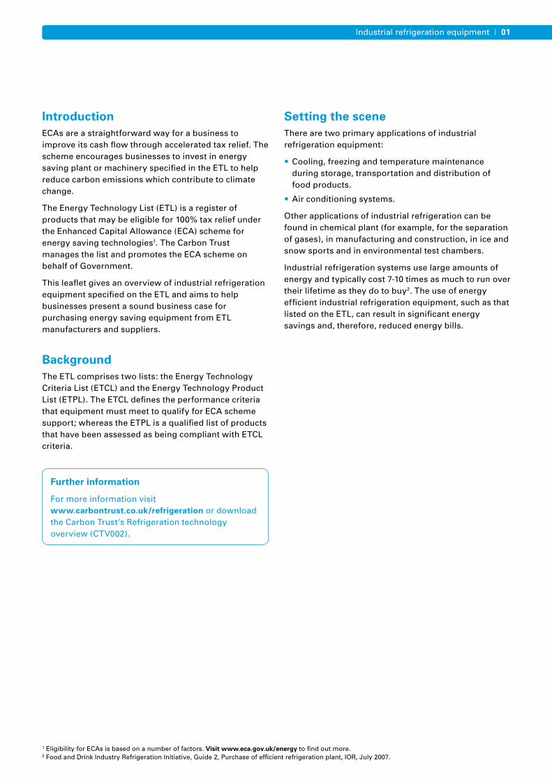
Industrial refrigeration equipment eligible under the ECA schemeThe following sections describe the refrigeration equipment specified as energy saving under the ECA scheme. The diagram below illustrates these ECA-eligible components and their relationship to each other.
Using the baseline scenario below, where appropriate the potential financial (£), energy (kWh) and carbon savings (tonnes CO2) have been calculated for replacing component parts of a refrigeration system with ETL-qualifying equipment to highlight the potential benefits that can be achieved.
Baseline scenario:
• Refrigeration plant with an installed cooling capacity of 400kW
• Producing chilled water at 5°C
• Compressor power demand of 100kW
• Annual operating hours: 8,000
• Electricity price 7.9p/kWh
• Electricity CO2 emission factor: 0.43kg CO2/kWh
• Annual savings do not degrade.
Important
Businesses purchasing equipment must check the ETPL at the time of purchase in order to verify that the named product they intend to purchase is designated as energy saving equipment. Industrial refrigeration equipment that meets the ETL eligibility criteria but is not listed on the Energy Technology Product List (ETPL) at the time of purchase is not eligible for an ECA.
Automaticair purge
Evaporativecondensers
Condensers
Expansion valve
Liquid pressure
amplification
Evaporators
Refrigerant leak
detection
Compressors
Refrigerationcompressors
Absorption chillers
System controls
Figure 1 Industrial refrigeration equipment eligible under the ECA scheme
03Industrial refrigeration equipment
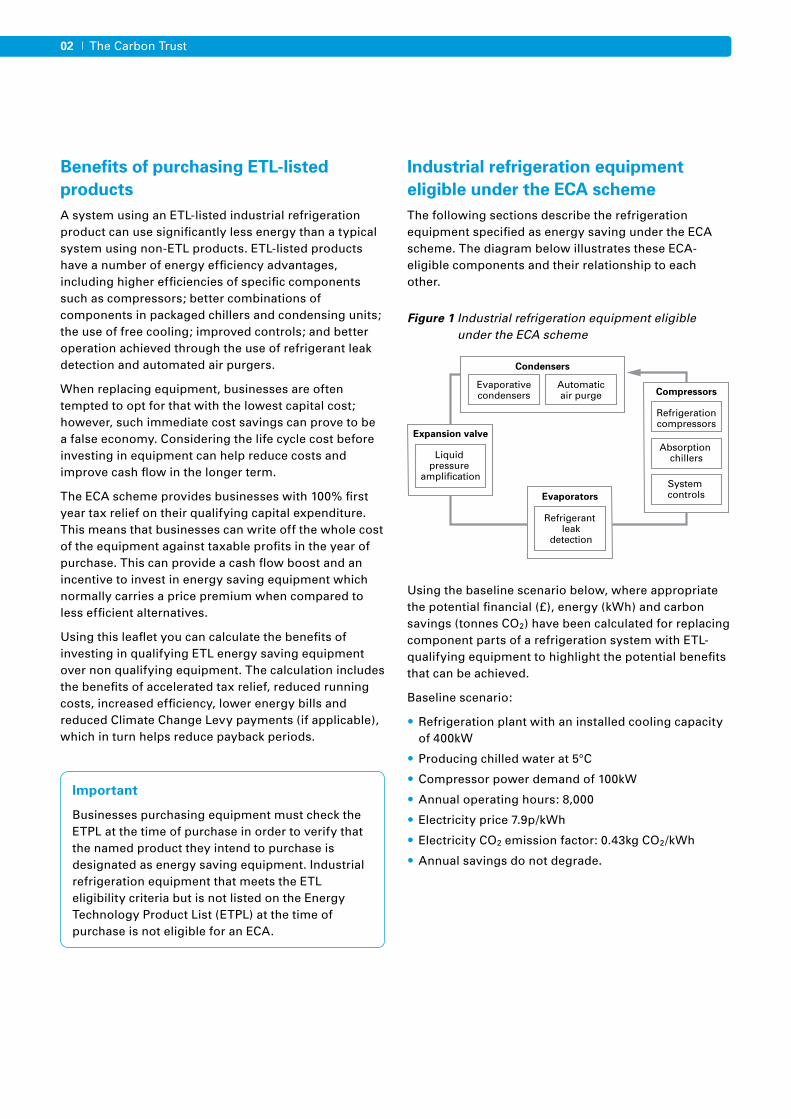
Absorption coolers
Absorption coolers (chillers) are heat-driven (as opposed to electrically driven) machines used in industrial refrigeration to cool a process or product. They operate using an absorption refrigeration cycle. In this cycle, two fluids are used – a refrigerant in conjunction with an ‘absorber’ – which have a high mutual solubility. Most commercially available absorption chillers use either ammonia and water or water and lithium bromide. Figure 2 shows the absorption refrigeration cycle. The compressor of the conventional system is replaced by an absorber and generator. The refrigerant vapour from the evaporator is absorbed at low pressure and low temperature. The resulting solution is then pumped to high pressure and heated in the generator where the refrigerant is released. The remainder of the cycle is conventional.
Absorption chillers may be driven by waste heat from thermal processes, and in particular from combined heat and power (CHP) systems. This offers significant benefits to CHP schemes since the additional heat load may increase the CHP plant running hours and the plant size, and also the electrical demand of the site will be reduced.
ECAs are available for absorption chillers used in conjunction with a CHP scheme that has been awarded a certificate from the CHP Quality Assurance (CHPQA) Programme3.
Air-cooled condensing units
An air-cooled condensing unit consists of a compressor and an air-cooled condenser combined with various ancillary components such as a liquid receiver, shut off valves, filter drier, sight glass and controls. The unit is factory assembled and wired as a complete unit. It provides a convenient method for ‘powering’ a cold room or other cooling equipment that has an evaporator with expansion valve control. Refrigerant vapour from the evaporator is compressed and condensed for return to the evaporator as a high pressure liquid. This process is shown in Figure 3, below.
By installing an ETL-listed absorption chiller in place of a baseline scenario refrigeration system (400kW chiller), the potential annual savings are calculated as:
• £63,000
• 800,000kWh
• 344 tonnes CO2.
In this scenario the absorption cooler is using waste heat from a CHP plant. The heat is assumed to be free.
Condenser
Evaporator
Heat exchanger
Absorber
Generator
Expansionvalve
Solutionpump
Pressurereducingdevice
Strong solution
Weak solution
Equivalent to the compressor ina vapour compression system
3 CHP Quality Assurance (CHPQA) Programme (www.chpqa.com)
Condenser
Heat in
Heat out
Condensing unit
ExpansionValve
Cold roomEvaporator
Compressor
Figure 2 Absorption refrigeration cycle
Figure 3 Simple refrigeration circuit showing condensing unit linked by two pipes to a typical cooling load
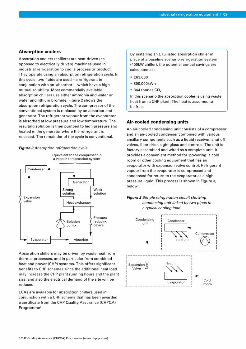
Medium and low temperature condensing units are widely used for frozen and chilled food storage. Evaporating temperatures are typically –35°C for frozen product and –10°C for chilled product. High temperature units are used in air conditioning applications. Figure 4 shows a typical air-cooled condensing unit.
The energy efficiency of an air-cooled condensing unit is dependent on refrigerant and operating conditions and is expressed as a Coefficient of Performance (COP)4. The rating conditions for condensing units are set out in EN 132155. The threshold eligibility values for COP for low and medium temperature applications with refrigerant R404A and for high temperature applications with refrigerant R407C are specified in the ECA criteria. In order to be eligible for an ECA, the unit must be rated at one or more of these conditions.
Efficiency can be enhanced by liquid sub-cooling within the unit. This can be achieved by using either additional dedicated coils in the condenser or two-stage or economised cycles. In order to be eligible for an ECA, the additional sub-cooling method and liquid temperature must be stated.
Automatic leak detection
Automated permanent refrigerant leak detection systems are products designed to continuously monitor the atmosphere in the vicinity of refrigeration equipment and, in the event of detection of refrigerant, raise an alarm. The early warning of refrigerant leaks allows repairs to be carried out early. This improves the energy efficiency of the refrigeration system and reduces carbon emissions and other greenhouse gases.
The majority of industrial refrigeration systems currently use either an HCFC or HFC refrigerant. Some systems use ammonia; however, ammonia detection devices are currently outside the scope of the ETL.
Refrigerant leakage may lead to a reduction in the efficiency of refrigeration equipment by causing a direct reduction in COP. Leaking systems can therefore contribute twice to climate change; once through the direct emission of refrigerant, and secondly through increased emissions from higher electricity consumption.
A recent estimate suggested that average refrigerant leakage rates are around 20% of total charge per year, and that typically a leaking system experiences an 11% reduction in COP6.
Automatic permanent leak detection systems are usually multi-point or single point sensing devices. A single point detector is a self-contained device installed in a plant room in a location where it is likely to detect the early onset of leakage. Multi-point detectors are often aspirated (they draw or suck air down tubes from each sample point to a central detector unit and control panel) and can typically monitor up to 16 locations.
04 The Carbon Trust
By installing an ETL-listed air-cooled condensing unit in place of one that is 25% less efficient, the potential annual savings are calculated as:
• £890
• 11,300kWh
• 4.8 tonnes CO2.
Based on the following scenario:
– 11kW continuous load at -20°C with the condensing unit running approximately 20h/day
– Refrigerant R404A
– No condensing pressure control i.e. pressure allowed to fall at low ambient conditions.
4 Defined as the ratio of cooling capacity to electrical power input, (including both compressor condenser fan power).5 European Standard EN13215 Condensing units for refrigeration – Rating conditions – tolerances and presentation of manufacturer’s performance data, 2000.6 Gartshore J. Energy Efficiency and Leakage Reduction. Refrigeration: Optimising refrigeration systems for building services engineers. CIBSE 2008.
Figure 4 Condensing unit showing compressor compartment
Image courtesy of Hubbard Products Ltd
05Industrial refrigeration equipment
Automatic leak detection systems eligible for ECAs must be able to continuously and permanently monitor the refrigeration system for refrigerant leakage by detecting the presence of one or more specified refrigerants. They must also raise an audible alarm when the level of refrigerant in the atmosphere exceeds a specified level.
Automatic air purgers
Automatic air purgers continuously purge non-condensable gases (such as air) from the condenser and receiver of a refrigeration system in order to reduce condenser pressure (also known as head pressure). This reduces compressor power use and increases the cooling capacity of the plant.
The presence of non-condensable gases increases head pressure in two ways: the partial pressure of the non-condensable gas adds to the partial pressure of the refrigerant gas to increase the total head pressure, and the non-condensable gases reduce the heat transfer rate in the condenser. These non-condensable gases may become introduced during maintenance and can leak into the system, or they may result from the breakdown of refrigerants and oils.
Automatic air purgers are generally suited to larger refrigeration plant, where the build up of non-condensable gases is a recurring problem.
Refrigeration system controls
Refrigeration system controllers vary enormously in function and complexity. The simplest control is a thermostat which simply controls the temperature of the cooled space. More complex refrigeration systems, such as those with multiple compressors, ideally require more sophisticated control. When used in the right way, these controls can significantly reduce the amount of energy a refrigeration system uses.
The ETPL currently includes system manager controls (with optimisation and energy log) and anti-condensation heater controls. System manager controls are computer-based systems that integrate and monitor the other control devices in the system to optimise performance and monitor energy consumption. For example, some controls monitor ambient temperature and/or load to determine optimum condensing and/or evaporating pressures.
Using the baseline scenario below, the potential financial (£), energy (kWh) and carbon savings (tonnes CO2) have been calculated for the use of an ETL-listed refrigeration system controllers.
Evaporative condensers
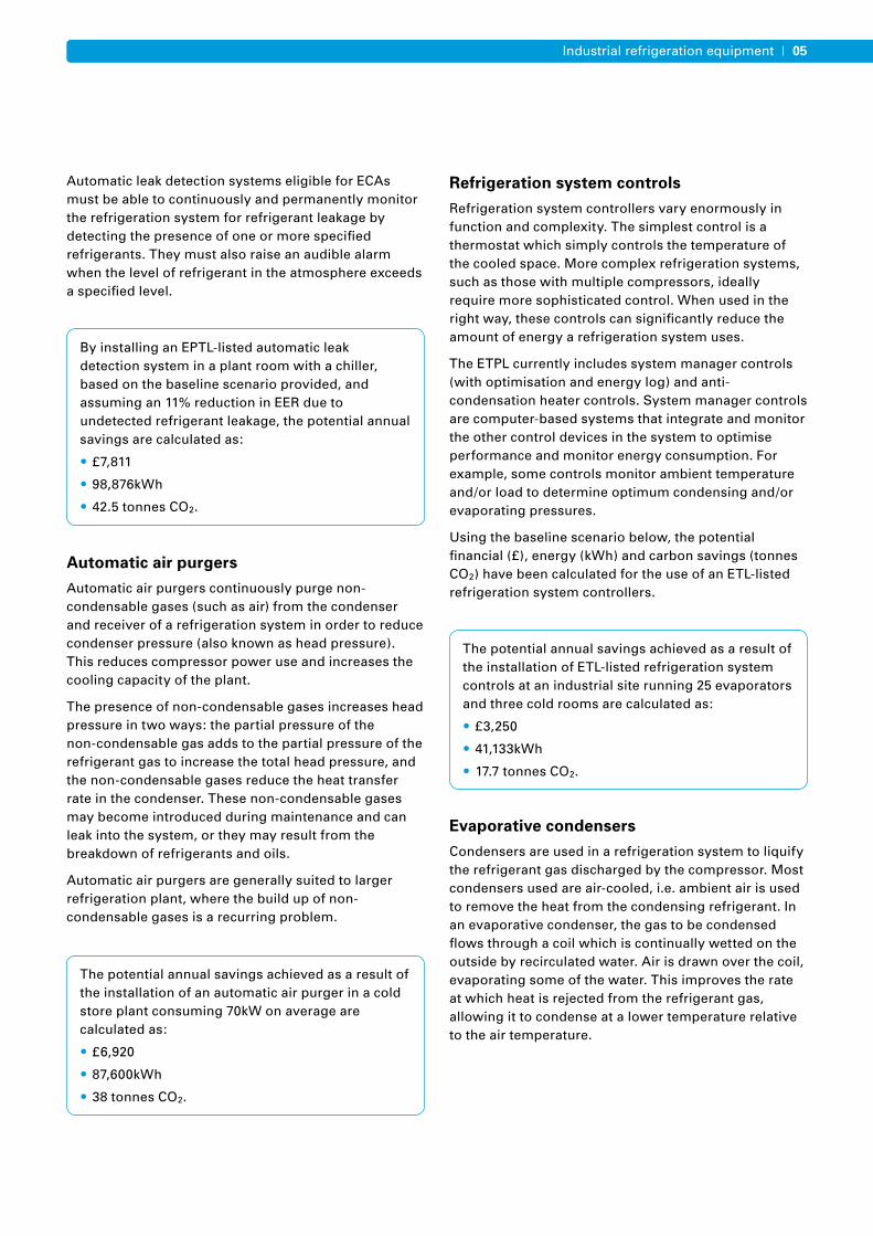
Condensers are used in a refrigeration system to liquify the refrigerant gas discharged by the compressor. Most condensers used are air-cooled, i.e. ambient air is used to remove the heat from the condensing refrigerant. In an evaporative condenser, the gas to be condensed flows through a coil which is continually wetted on the outside by recirculated water. Air is drawn over the coil, evaporating some of the water. This improves the rate at which heat is rejected from the refrigerant gas, allowing it to condense at a lower temperature relative to the air temperature.
By installing an EPTL-listed automatic leak detection system in a plant room with a chiller, based on the baseline scenario provided, and assuming an 11% reduction in EER due to undetected refrigerant leakage, the potential annual savings are calculated as:
• £7,811
• 98,876kWh
• 42.5 tonnes CO2.
The potential annual savings achieved as a result of the installation of an automatic air purger in a cold store plant consuming 70kW on average are calculated as:
• £6,920
• 87,600kWh
• 38 tonnes CO2.
The potential annual savings achieved as a result of the installation of ETL-listed refrigeration system controls at an industrial site running 25 evaporators and three cold rooms are calculated as:
• £3,250
• 41,133kWh
• 17.7 tonnes CO2.
06 The Carbon Trust
Liquid pressure amplification
Liquid pressure amplification (LPA) involves the use of a pump between the condenser and the expansion valve in a refrigeration system. This pump raises the liquid pressure at the expansion valve allowing the head pressure to be lowered. This reduces the power required by the compressor (increasing the COP) to achieve a given amount of cooling.
Many refrigeration systems operate with higher head pressures than necessary. Without controls, head pressures would be lower in mild and colder weather compared with hotter days. However, because of constraints on the pressure, systems generally have controls that maintain the head pressure at high levels by, for example, cycling condenser fans on and off.
LPA provides a means of operating at lower head pressures while still satisfying the constraints on liquid pressure. On a typical installation, test data shows that savings of 20% of power use (average over a whole year) are typical7.
It is estimated that head pressure control is present on some 80% of all installed refrigeration systems. However, LPA is only cost effective on the larger systems using more than approximately 250,000kWh a year of electricity (worth £20,000 a year)8.
By installing an ETL-listed evaporative condenser in place of an air-cooled condenser on a system with 500kW heat rejection, the potential annual savings are calculated as:
• £6,470
• 81,866kWh
• 35.2 tonnes CO2.
Assuming that the minimum condensing temperature in both systems is 20°C, fan and pump power are the same and the cost of water treatment for the evaporative condenser is not included.
10
9
2
3
4
81
7
6
5
Figure 5 Diagram showing typical evaporative condenser operation
The potential annual savings shown are based on comparison between a conventional refrigeration system with head pressure controls and one fitted with an ETL-listed LPA system.
• £13,120
• 160,000kWh
• 69 tonnes CO2.
7 ECA LPA Technology Review.8 ECA LPA Technology Review.
1. Air in 2. Air out 3. Vapour in 4. Liquid out 5. Cold water basin
6. Water distribution system 7. Coil 8. Spray water pump 9. Eliminators 10. Optional extended surface.
07Industrial refrigeration equipment
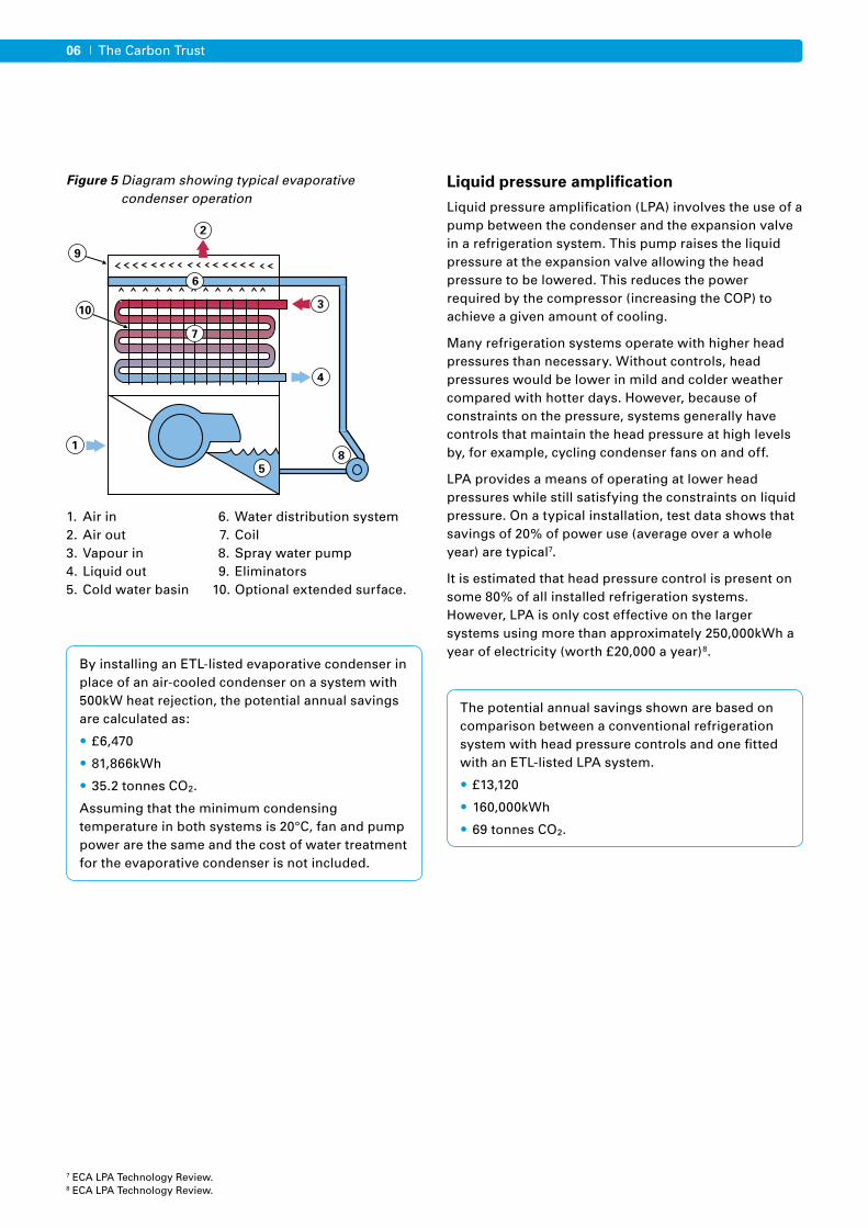
Packaged chillers
Packaged chillers are factory assembled refrigeration units that are designed to cool liquid using a self contained, electrically-driven mechanical vapour compression system. A packaged chiller includes the refrigeration compressor(s), controls and the evaporator in the packaged unit. The condenser may be built-in or remote. Some packaged chillers may also include a hydronic unit comprising a chilled water buffer tank and a chilled water circulation pump.
• Air-cooled packaged chillers
• Water-cooled packaged chillers
• Packaged chillers with remote air-cooled condensers
Packed chillers eligible for ECAs include chillers designed for the following air conditioning and refrigeration (including process cooling) applications:
• Air conditioning, with a leaving chilled water temperature of +7°C
• Medium brine, with a leaving brine temperature of -5°C
• Low brine, with a leaving brine temperature of -15°C.
These chillers may operate with any type of electrically driven compressor, use any refrigerant, and can be air-cooled, water-cooled, evaporatively-cooled or have a remote condenser. They may be cooling-only or reverse cycle.
By installing an EPTL listed 500kW air cooled packaged chiller the potential annual savings are calculated as:
• £878
• 11,111kWh
• 4.78 tonnes CO2.
Based on the following scenario:
• Installation of one 500kW capacity air cooled packaged chiller with an average EER of 2.5.
• Replacement of a 500kW air cooled packaged chiller which has an average EER of 2.25.
• The chiller serves an air conditioning load and operates for 500 hours per year.
Note that an EER of 2.25 is the minimum EER value for compliance with the current Building Regulations ADL guidance and also corresponds to Eurovent class F.
Compressor
Evaporator
Control panel
Chilled water pump
Finned coil condenser
Chilled water inlet & outlet
Condenser fans
Compressor
Evaporator
Control panel
Chilled water pump
Chilled water inlet & outlet
Water connections to dryair cooler or cooling tower
Condenser
Compressor
Evaporator
Control panel
Chilled water pump
Chilled water inlet & outlet
Refigerant connections toremote air cooled condenser or
evaporative condensers
Compressor
Evaporator
Control panel
Chilled water pump
Finned coil condenser
Chilled water inlet & outlet
Condenser fans
Compressor
Evaporator
Control panel
Chilled water pump
Chilled water inlet & outlet
Water connections to dryair cooler or cooling tower
Condenser
Compressor
Evaporator
Control panel
Chilled water pump
Chilled water inlet & outlet
Refigerant connections toremote air cooled condenser or
evaporative condensers
08 The Carbon Trust
Refrigeration compressors
The compressor in a refrigeration system compresses the refrigerant gas from the low pressure of the evaporator to a higher pressure so that it can condense in the condenser, thus rejecting heat to ambient air or water.
The following most common compression methods are included on the ETL:
Reciprocating – where pistons in bores compress the refrigerant gas.
Rotary scroll – where an orbiting scroll moves against a fixed scroll, thus continually compressing the gas.
Screw – where one or two screws mesh together to continually compress the gas.
The compressor and motors are housed either in a hermetic enclosure which is welded tight, or in a semi hermetic enclosure which has gasketed removable covers. Both types are eligible for ECAs.
By installing an ETL-listed compressor instead of a 15% less efficient one, the potential annual savings are calculated as:
• £1,010
• 12,800kWh
• 5.5 tonnes CO2.
Based on the following scenario:
• 40kW continuous load at +5°C with the compressor running approximately 20h/day.
• Refrigerant R404A.
• Condensing temperature 10K above ambient, with pressure allowed to fall at low ambient conditions to a minimum condensing condition of 20°C.
Information for purchasers
For further information about the ECA scheme, the Energy Technology List (ETL) and other Technology Information Leaflets in the series please visit www.carbontrust.co.uk/eca, contact the Carbon Trust on 0800 085 2005 or email [email protected]

09Industrial refrigeration equipment
Calculating the payback of your investmentBased on the operating conditions above, indicative savings can be calculated for replacing your existing equipment with either ETL-listed equipment or non-ETL-listed equipment.
The accelerated tax relief and cash flow benefit provided by the ECA, together with the life cycle cost savings from ETL-listed equipment, aid in bridging the price premium and shortening the investment payback period9.
To calculate the payback period for ETL-listed equipment and non-ETL-listed equipment for comparison you will need:
• The unit price (kW) of the energy your business consumes.
• Estimated energy usage (kW) for the ETL proposed equipment solution(s), which the manufacturer or supplier should be able to help you with.
• Estimated energy usage (kW) for the non-ETL proposed equipment solution(s), which the manufacturer or supplier should be able to help you with.
• Estimated annual maintenance costs incurred by your business for the ETL-listed equipment (your manufacturer or supplier should be able to help you with estimates).
• Estimated annual maintenance costs incurred by your business for the non-ETL-listed equipment (your manufacturer or supplier should be able to help you with estimates).
• The value of the proposed capital expenditure.
• Your business’s corporation tax rate.
In addition, the following information is also required:
• A copy of the Carbon Trust fact sheet Energy and carbon conversion (CTL004).
• Incorporation of the fact that capital allowance (CA) tax relief for non ETL equipment is 20% (10% if allocated to the ‘special rate’ pool) and that enhanced capital allowance (ECA) tax relief for ECA equipment is 100%.
Step 1: To prepare your business case for investment you first need to estimate annual energy consumption of the ETL-listed equipment and non-ETL-listed equipment.
Additionally, you can calculate the carbon emissions associated with the energy consumption using either the Carbon Trust fact sheet Energy and carbon conversion (CTL004) or by using the tool at www.carbontrust.co.uk/conversionfactors by simply multiplying the energy consumption by the carbon emission factor for that fuel type.
Step 2: Calculate the annual running cost (ARC) of ETL-listed equipment and non-ETL-listed equipment.
Step 1 and 2 can also be done for your existing equipment to calculate an ARC, in order to allow comparisons of the annual saving (step 3) between the existing equipment, the ETL-listed equipment, and the non-ETL-listed equipment.
Step 3: Calculate the annual saving between the ETL-listed annual running costs and non-ETL-listed annual running costs.
Annual energy consumption
(kWh/y)
Equipmentconsumption (kW)
= xNumber of operating hours/year
Carbonemissions
Annual energyconsumption (kW) = x
Emission factor(kg CO2 /kWh)
ARCAnnual energy
consumption (kW)Pence/kWh= x +
Annualmaintenance
cost
Annual saving
ARC of newequipment
ARC of existingequipment
= -
9 The values used in the examples given are for illustrative purposes only and do not reflect specific case studies. Anyone considering purchasing this type of equipment would be advised to also analyse the benefits that would be available based on their own circumstances. It should also be noted that the use of formally trained heating, ventilation and air conditioning equipment technicians can provide significant energy saving benefits.
10 The Carbon Trust
* 10% if allocated to the special rate pool
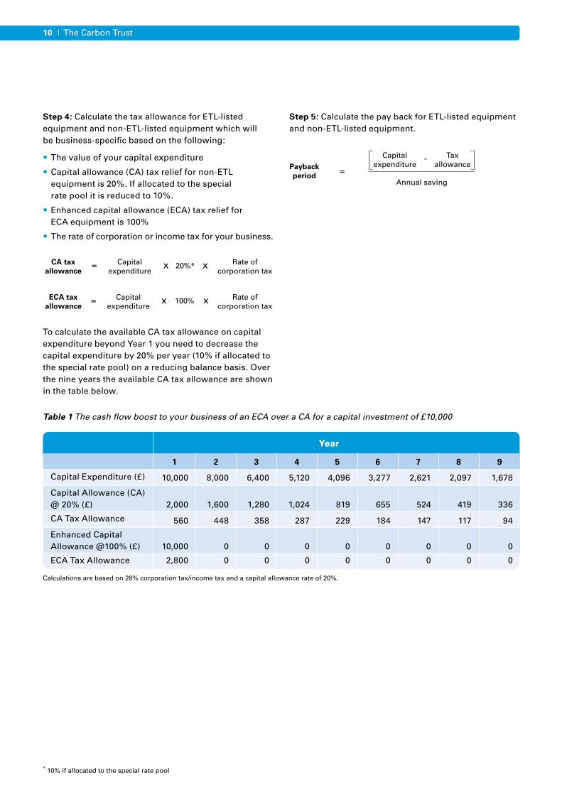
Step 4: Calculate the tax allowance for ETL-listed equipment and non-ETL-listed equipment which will be business-specific based on the following:
• The value of your capital expenditure
• Capital allowance (CA) tax relief for non-ETL equipment is 20%. If allocated to the special rate pool it is reduced to 10%.
• Enhanced capital allowance (ECA) tax relief for ECA equipment is 100%
• The rate of corporation or income tax for your business.
To calculate the available CA tax allowance on capital expenditure beyond Year 1 you need to decrease the capital expenditure by 20% per year (10% if allocated to the special rate pool) on a reducing balance basis. Over the nine years the available CA tax allowance are shown in the table below.
Step 5: Calculate the pay back for ETL-listed equipment and non-ETL-listed equipment.
ECA taxallowance
Capital expenditure
= x x Rate ofcorporation tax
100%
Payback period
Capitalexpenditure
=- Tax
allowance
Annual saving
1 2 3 4 5 6 7 8 9
Capital Expenditure (£) 10,000 8,000 6,400 5,120 4,096 3,277 2,621 2,097 1,678
Capital Allowance (CA) @ 20% (£) 2,000 1,600 1,280 1,024 819 655 524 419 336
CA Tax Allowance 560 448 358 287 229 184 147 117 94
Enhanced Capital Allowance @100% (£)
10,000
0
0
0
0
0
0
0
0
ECA Tax Allowance 2,800 0 0 0 0 0 0 0 0
Year
Calculations are based on 28% corporation tax/income tax and a capital allowance rate of 20%.
Table 1 The cash flow boost to your business of an ECA over a CA for a capital investment of £10,000
CA taxallowance
Capital expenditure
= x x Rate ofcorporation tax
20%*

The Carbon Trust provides a range of tools, services and information to help you implement energy and carbon saving measures, no matter what your level of experience.
Carbon Footprint Calculator – Our online calculator will help you calculate your organisation’s carbon emissions.
www.carbontrust.co.uk/carboncalculator
Interest Free Loans – Energy Efficiency Loans from the Carbon Trust are a cost effective way to replace or upgrade your existing equipment with a more energy efficient version. See if you qualify.
www.carbontrust.co.uk/loans
Carbon Surveys – We provide surveys to organisations with annual energy bills of more than £50,000*. Our carbon experts will visit your premises to identify energy saving opportunities and offer practical advice on how to achieve them.
www.carbontrust.co.uk/surveys
Action Plans – Create action plans to implement carbon and energy saving measures.
www.carbontrust.co.uk/apt
Case Studies – Our case studies show that it’s often easier and less expensive than you might think to bring about real change.
www.carbontrust.co.uk/casestudies
Events and Workshops – The Carbon Trust offers a variety of events and workshops ranging from introductions to our services, to technical energy efficiency training, most of which are free.
www.carbontrust.co.uk/events
Publications – We have a library of free publications detailing energy saving techniques for a range of sectors and technologies.
www.carbontrust.co.uk/publications
Need further help? Call our Customer Centre on 0800 085 2005 Our Customer Centre provides free advice on what your organisation can do to save
energy and save money. Our team handles questions ranging from straightforward requests for information, to in-depth technical queries about particular technologies.
Go online to get more
* Subject to terms and conditions.
The Carbon Trust is funded by the Department of Energy and Climate Change (DECC), the Department for Business, Enterprise and Regulatory Reform (BERR), the Scottish Government, the Welsh Assembly Government and Invest Northern Ireland.
Whilst reasonable steps have been taken to ensure that the information contained within this publication is correct, the authors, the Carbon Trust, its agents, contractors and sub-contractors give no warranty and make no representation as to its accuracy and accept no liability for any errors or omissions. Any trademarks, service marks or logos used in this publication, and copyright in it, are the property of the Carbon Trust. Nothing in this publication shall be construed as granting any licence or right to use or reproduce any of the trademarks, service marks, logos, copyright or any proprietary information in any way without the Carbon Trust’s prior written permission. The Carbon Trust enforces infringements of its intellectual property rights to the full extent permitted by law.
The Carbon Trust is a company limited by guarantee and registered in England and Wales under Company number 4190230 with its Registered Office at: 6th Floor, 5 New Street Square, London EC4A 3BF.
Published in the UK: December 2008.
© The Carbon Trust 2009. All rights reserved. ECA768 v2
The Carbon Trust was set up by Government in 2001 as an independent company.
Our mission is to accelerate the move to a low carbon economy by working with organisations to reduce carbon emissions and develop commercial low carbon technologies.
We do this through five complementary business areas:
Insights – explains the opportunities surrounding climate change Solutions – delivers carbon reduction solutions Innovations – develops low carbon technologies Enterprises – creates low carbon businesses Investments – finances clean energy businesses.
www.carbontrust.co.uk0800 085 2005