Embed Size (px)
Citation preview
products Panel Relays General information
General InformationApplication GuideBreaking CapacityApprovals
General Information
Contacts There are different types of contacts. The biggest difference isnoticed between single contacts and twin contacts. While singlecontacts are best for higher loads, twin contacts are significantlymore reliable for small loads, such as <24 V, <100 mA.
Contact material No contact is right for all situations.AgNi is used as standard material for most applications. AgNicontacts with a hard gold-plating (up to 10 µm) are available forapplications in aggressive environments.Relays with gold-plated contacts are approved for relatively highcurrents (e.g., 6 A, 250 V), but in practice, loads above 200 mA, 30 Vshould not be switched with intact gold-plated contacts.Relays with tungsten contacts can be used with high inrush currents(up to 500 A for 2.5 ms). There are also AgNi contacts with smallamounts of gold (0.2 µm). This is only used as protection againstcorrosion during storage.
Minimum loads The minimum load value is a recommended value under normalconditions, such as regular activation and drop out, no unusualenvironmental conditions, etc. Under these conditions, reliable relayfunction can be anticipated. Contact resistance In practice, contact resistance can vary depending on the load andother conditions. For higher currents, contact resistance is about 10mΩ. For very low loads, the resistance can be over 1 Ω.
Contact gap All contacts normally have an air gap of between 0.5 and 1.5 mmwhen they are open. This type of contact is called a µ contact.According to the low-voltage directive and the associated standards,contacts of this type are not suitable as safety switches.When DC loads are connected and disconnected, a large contactgap is advantageous in extinguishing the arc that occurs with thistype of load. Series connection of relays can be utilised for thispurpose.
Coils Powering of a relay is dependent on the coil and connections. Thecoil has a special character depending on the operating voltage andthe type of current.
Industrial Relays, General Information
WWW.OEM.CO.UK, [email protected], TEL: +44 (0) 116 284 9900, FAX: +44 (0) 116 284 1721
Breaking capacity Contacts' breaking capacity is the sum of the breaking voltage andcurrent.For AC, the permitted breaking capacity is generally sufficiently highto withstand the maximum constant AC1 load throughout the voltagerange. For DC, the current limit's curve may never be exceeded. Thiscan lead to a residual arc that causes immediate failure of the relay.The breaking capacity level for DC is about 100 W (DC1).
Coil resistance Each coil has a coil resistance that can be measured with anohmmeter. The specified coil resistance is measured at 20 °C. Thetolerance is ±10 %. For AC operation, the coil current will not matchthe resistance value due to self-inductance having a dominant effect.At 230 V AC, this can be more than 90 H. When a relay breakscurrent, the self-inductance results in an internal voltage that canaffect the breaking position, destroy transistors or create EMCproblems.
Coil construction The coil consists of a plastic housing, heat resistance up to 130 °Cand dual-isolated, pure copper wire, temperature class F. Thewinding must withstand an isolation voltage per EN 61000-4-5 ofover 2000 V. This is assured with a forced separation at thebeginning and end of the winding.
Holding and drop-out voltage The holding voltage is the voltage at which the relay is guaranteed toremain in the activated position. The limit at which the relay becomesunstable for DC is about 25 % of Unom, and for AC about 60 %. Thedrop-out voltage for DC is 65 % and AC 75 %.For DC, these voltages are very temperature dependent, according tothe temperature coefficient Cu. This is not the case with AC, wherethe inductive resistance is the controlling factor. This is largelyconstant over a wide temperature range.For AC, and within a certain range of under-voltages, humming canbe emitted from the relay or vibrations can occur in the relay housing.This voltage range should be avoided.
Operating voltage There is a difference between the voltage that is standardised per EN60947 and what is guaranteed for the relay, and the typical valuesthat can most likely be expected during operation. Operating voltage range The operating voltage is the range in which the relay functions satisfactorily. If not otherwise indicated, the relay's normal operating voltageis between +10 % and -20 % of Unom. This range is very temperature sensitive and narrows when the ambient temperature and relaytemperature increase. The upper operating voltage limit has a steeper curve than the lower limit. At about 70 °C, the operating voltagetolerance is equal to zero.
WWW.OEM.CO.UK, [email protected], TEL: +44 (0) 116 284 9900, FAX: +44 (0) 116 284 1721
Application Guide
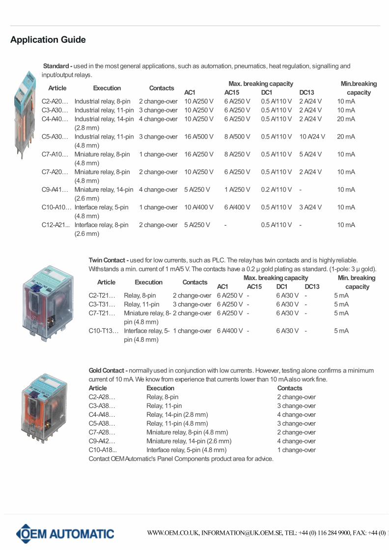
Standard - used in the most general applications, such as automation, pneumatics, heat regulation, signalling andinput/output relays.
Article Execution Contacts Max. breaking capacity Min.breakingcapacityAC1 AC15 DC1 DC13
C2-A20… Industrial relay, 8-pin 2 change-over 10 A/250 V 6 A/250 V 0.5 A/110 V 2 A/24 V 10 mAC3-A30… Industrial relay, 11-pin 3 change-over 10 A/250 V 6 A/250 V 0.5 A/110 V 2 A/24 V 10 mAC4-A40… Industrial relay, 14-pin
(2.8 mm)4 change-over 10 A/250 V 6 A/250 V 0.5 A/110 V 2 A/24 V 20 mA
C5-A30… Industrial relay, 11-pin (4.8 mm)
3 change-over 16 A/500 V 8 A/500 V 0.5 A/110 V 10 A/24 V 20 mA
C7-A10… Miniature relay, 8-pin (4.8 mm)
1 change-over 16 A/250 V 8 A/250 V 0.5 A/110 V 5 A/24 V 10 mA
C7-A20… Miniature relay, 8-pin (4.8 mm)
2 change-over 10 A/250 V 6 A/250 V 0.5 A/110 V 2 A/24 V 10 mA
C9-A41… Miniature relay, 14-pin (2.6 mm)
4 change-over 5 A/250 V 1 A/250 V 0.2 A/110 V - 10 mA
C10-A10… Interface relay, 5-pin (4.8 mm)
1 change-over 10 A/400 V 6 A/400 V 0.5 A/110 V 3 A/24 V 10 mA
C12-A21... Interface relay, 8-pin (2.6 mm)
2 change-over 5 A/250 V - 0.5 A/110 V - 10 mA
Twin Contact - used for low currents, such as PLC. The relay has twin contacts and is highly reliable.Withstands a min. current of 1 mA/5 V. The contacts have a 0.2 µ gold plating as standard. (1-pole: 3 µ gold).
Article Execution Contacts Max. breaking capacity Min. breaking capacityAC1 AC15 DC1 DC13
C2-T21… Relay, 8-pin 2 change-over 6 A/250 V - 6 A/30 V - 5 mAC3-T31… Relay, 11-pin 3 change-over 6 A/250 V - 6 A/30 V - 5 mAC7-T21… Miniature relay, 8-
pin (4.8 mm)2 change-over 6 A/250 V - 6 A/30 V - 5 mA
C10-T13… Interface relay, 5-pin (4.8 mm)
1 change-over 6 A/400 V - 6 A/30 V - 5 mA
Gold Contact - normally used in conjunction with low currents. However, testing alone confirms a minimumcurrent of 10 mA. We know from experience that currents lower than 10 mA also work fine.Article Execution ContactsC2-A28… Relay, 8-pin 2 change-overC3-A38… Relay, 11-pin 3 change-overC4-A48… Relay, 14-pin (2.8 mm) 4 change-overC5-A38… Relay, 11-pin (4.8 mm) 3 change-overC7-A28… Miniature relay, 8-pin (4.8 mm) 2 change-overC9-A42… Miniature relay, 14-pin (2.6 mm) 4 change-overC10-A18... Interface relay, 5-pin (4.8 mm) 1 change-overContact OEM Automatic's Panel Components product area for advice.
WWW.OEM.CO.UK, [email protected], TEL: +44 (0) 116 284 9900, FAX: +44 (0) 116 284 1721
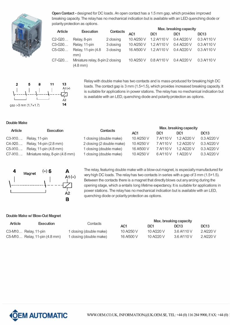
Open Contact - designed for DC loads. An open contact has a 1.5 mm gap, which provides improvedbreaking capacity. The relay has no mechanical indication but is available with an LED quenching diode orpolarity protection as options.
Article Execution Contacts Max. breaking capacityAC1 DC1 DC1 DC13
C2-G20… Relay, 8-pin 2 closing 10 A/250 V 1.2 A/110 V 0.4 A/220 V 0.3 A/110 VC3-G30… Relay, 11-pin 3 closing 10 A/250 V 1.2 A/110 V 0.4 A/220 V 0.3 A/110 VC5-G30… Relay, 11-pin (4.8
mm)3 closing 16 A/500 V 1.2 A/110 V 0.4 A/220 V 0.3 A/110 V
C7-G20… Miniature relay, 8-pin(4.8 mm)
2 closing 10 A/250 V 0.8 A/110 V 0.4 A/220 V 0.3 A/110 V
Relay with double make has two contacts and is mass-produced for breaking high DCloads. The contact gap is 3 mm (1.5+1.5), which provides increased breaking capacity. Itis suitable for applications in power stations. The relay has no mechanical indication butis available with an LED, quenching diode and polarity protection as options.
Double Make
Article Execution Contacts Max. breaking capacityAC1 DC1 DC1 DC13
C3-X10…. Relay, 11-pin 1 closing (double make) 10 A/250 V 7 A/110 V 1.2 A/220 V 0.3 A/220 VC4-X20…. Relay, 14-pin (2.8 mm) 2 closing (2 double make) 10 A/250 V 7 A/110 V 1.2 A/220 V 0.3 A/220 VC5-X10…. Relay, 11-pin (4.8 mm) 1 closing (double make) 16 A/500 V 7 A/110 V 1.2 A/220 V 0.3 A/220 VC7-X10…. Miniature relay, 8-pin (4.8 mm) 1 closing (double make) 10 A/250 V 6 A/110 V 1 A/220 V 0.3 A/220 V
The relay, featuring double make with a blow-out magnet, is especially manufactured forvery high DC loads. The relay has two contacts in series with a gap of 3 mm (1.5+1.5).Between the contacts there is a magnet that directly blows out any arcing during theopening stage, which a entails long lifetime expectancy. It is suitable for applications inpower stations. The relay has no mechanical indication but is available with an LED,quenching diode or polarity protection as options.
Double Make w/ Blow-Out Magnet
Article Execution ContactsMax. breaking capacity
AC1 DC1 DC13 DC13C3-M10… Relay, 11-pin 1 closing (double make) 10 A/250 V 10 A/220 V 3.6 A/110 V 2 A/220 VC5-M10… Relay, 11-pin (4.8 mm) 1 closing (double make) 16 A/500 V 10 A/220 V 3.6 A/110 V 2 A/220 V
WWW.OEM.CO.UK, [email protected], TEL: +44 (0) 116 284 9900, FAX: +44 (0) 116 284 1721
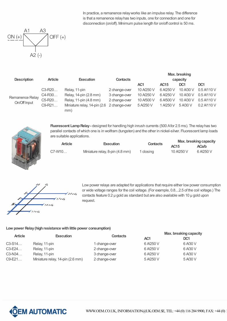
In practice, a remanence relay works like an impulse relay. The differenceis that a remanence relay has two inputs, one for connection and one for disconnection (on/off). Minimum pulse length for on/off control is 50 ms.
Description Article Execution ContactsMax. breaking
capacity AC1 AC15 DC1 DC1
Remanence RelayOn/Off Input
C3-R20… Relay, 11-pin 2 change-over 10 A/250 V 6 A/250 V 10 A/30 V 0.5 A/110 VC4-R30… Relay, 14-pin (2.8 mm) 3 change-over 10 A/250 V 6 A/250 V 10 A/30 V 0.5 A/110 VC5-R20… Relay, 11-pin (4.8 mm) 2 change-over 10 A/500 V 6 A/500 V 10 A/30 V 0.5 A/110 VC9-R21… Miniature relay, 14-pin (2.6
mm)2 change-over 5 A/250 V 1 A/250 V 5 A/30 V 0.2 A/110 V
Fluorescent Lamp Relay - designed for handling high inrush currents (500 A for 2.5 ms). The relay has twoparallel contacts of which one is in wolfram (tungsten) and the other in nickel-silver. Fluorescent lamp loadsare suitable applications.
Article Execution Contacts Max. breaking capacityAC15 ACa/b
C7-W10… Miniature relay, 8-pin (4.8 mm) 1 closing 10 A/250 V 6 A/250 V
Low power relays are adapted for applications that require either low power consumptionor wide voltage ranges for the coil voltage. (For example, 0.8....2.5 of the coil voltage.) Thecontacts feature 0.2 µ gold as standard but are also available with 10 µ gold uponrequest.
Low power Relay (high resistance with little power consumption)
Article Execution Contacts Max. breaking capacityAC1 DC1
C3-S14… Relay, 11-pin 1 change-over 6 A/250 V 6 A/30 VC3-E24… Relay, 11-pin 2 change-over 6 A/250 V 6 A/30 VC3-N34… Relay, 11-pin 3 change-over 6 A/250 V 6 A/30 VC9-E21… Miniature relay, 14-pin (2.6 mm) 2 change-over 5 A/250 V 5 A/30 V
WWW.OEM.CO.UK, [email protected], TEL: +44 (0) 116 284 9900, FAX: +44 (0) 116 284 1721
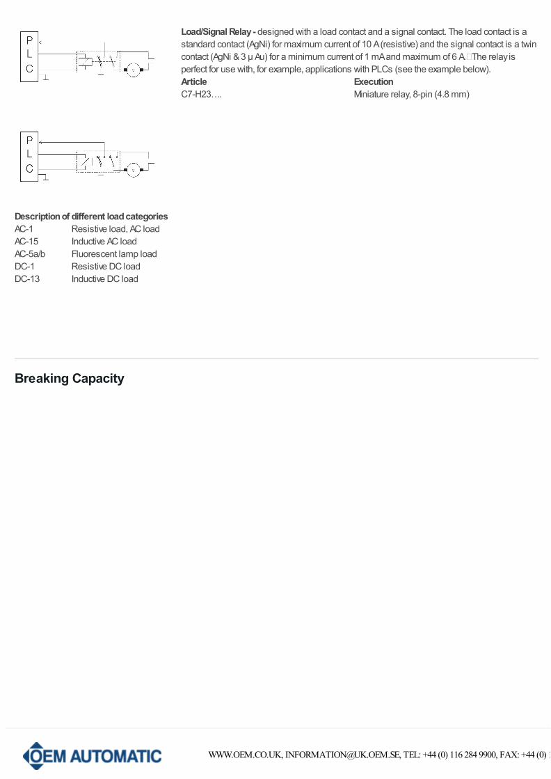
Load/Signal Relay - designed with a load contact and a signal contact. The load contact is astandard contact (AgNi) for maximum current of 10 A (resistive) and the signal contact is a twincontact (AgNi & 3 µ Au) for a minimum current of 1 mA and maximum of 6 A.�The relay isperfect for use with, for example, applications with PLCs (see the example below).Article ExecutionC7-H23…. Miniature relay, 8-pin (4.8 mm)
Description of different load categoriesAC-1 Resistive load, AC loadAC-15 Inductive AC loadAC-5a/b Fluorescent lamp loadDC-1 Resistive DC loadDC-13 Inductive DC load
Breaking Capacity
WWW.OEM.CO.UK, [email protected], TEL: +44 (0) 116 284 9900, FAX: +44 (0) 116 284 1721
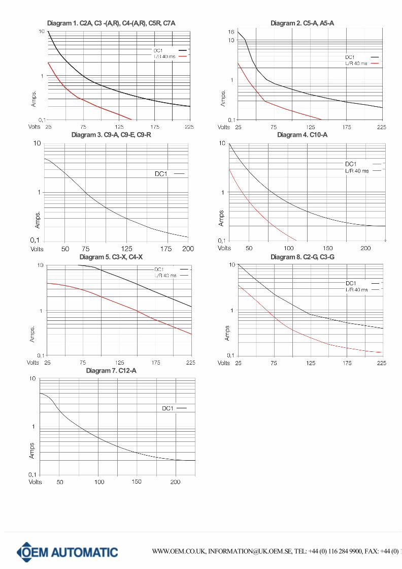
Diagram 1. C2A, C3 -(A,R), C4-(A,R), C5R, C7A Diagram 2. C5-A, A5-A
Diagram 3. C9-A, C9-E, C9-R Diagram 4. C10-A
Diagram 5. C3-X, C4-X Diagram 8. C2-G, C3-G
Diagram 7. C12-A
WWW.OEM.CO.UK, [email protected], TEL: +44 (0) 116 284 9900, FAX: +44 (0) 116 284 1721
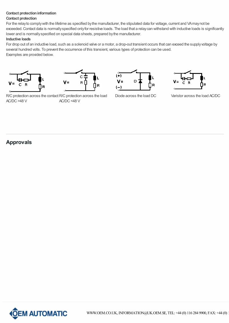
Contact protection informationContact protectionFor the relay to comply with the lifetime as specified by the manufacturer, the stipulated data for voltage, current and VA may not beexceeded. Contact data is normally specified only for resistive loads. The load that a relay can withstand with inductive loads is significantlylower and is normally specified on special data sheets, prepared by the manufacturer.Inductive loadsFor drop out of an inductive load, such as a solenoid valve or a motor, a drop-out transient occurs that can exceed the supply voltage byseveral hundred volts. To prevent the occurrence of this transient, various types of protection can be used.Examples are provided below.
R/C protection across the contactAC/DC >48 V
R/C protection across the loadAC/DC <48 V
Diode across the load DC Varistor across the load AC/DC
Approvals
WWW.OEM.CO.UK, [email protected], TEL: +44 (0) 116 284 9900, FAX: +44 (0) 116 284 1721
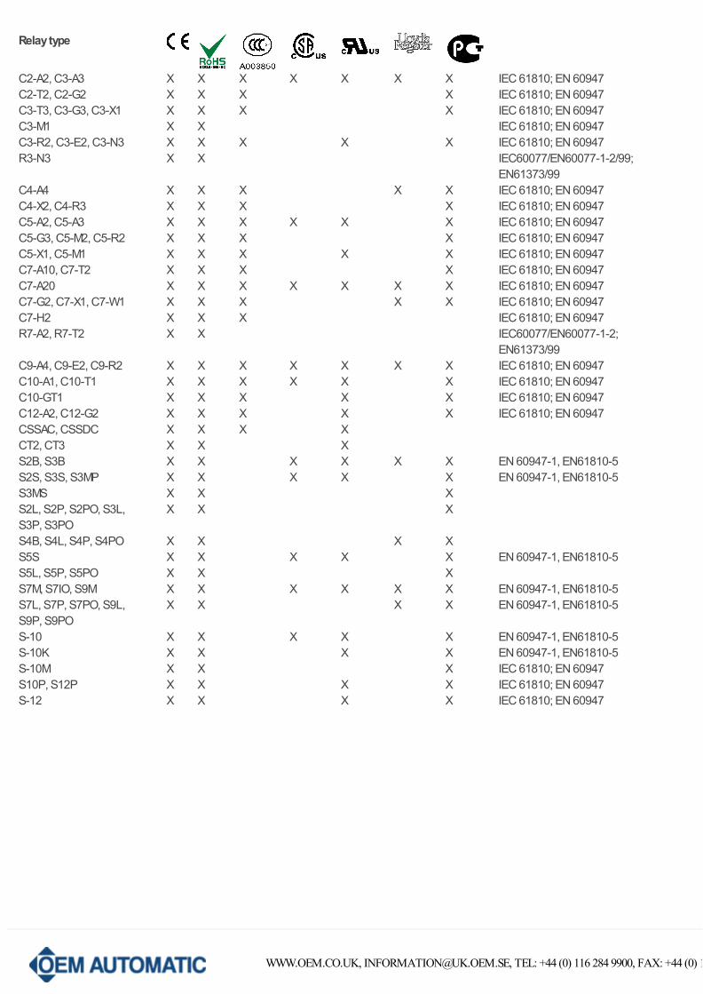
Relay type
C2-A2, C3-A3 X X X X X X X IEC 61810; EN 60947C2-T2, C2-G2 X X X X IEC 61810; EN 60947C3-T3, C3-G3, C3-X1 X X X X IEC 61810; EN 60947C3-M1 X X IEC 61810; EN 60947C3-R2, C3-E2, C3-N3 X X X X X IEC 61810; EN 60947R3-N3 X X IEC60077/EN60077-1-2/99;
EN61373/99C4-A4 X X X X X IEC 61810; EN 60947C4-X2, C4-R3 X X X X IEC 61810; EN 60947C5-A2, C5-A3 X X X X X X IEC 61810; EN 60947C5-G3, C5-M2, C5-R2 X X X X IEC 61810; EN 60947C5-X1, C5-M1 X X X X X IEC 61810; EN 60947C7-A10, C7-T2 X X X X IEC 61810; EN 60947C7-A20 X X X X X X X IEC 61810; EN 60947C7-G2, C7-X1, C7-W1 X X X X X IEC 61810; EN 60947C7-H2 X X X IEC 61810; EN 60947R7-A2, R7-T2 X X IEC60077/EN60077-1-2;
EN61373/99C9-A4, C9-E2, C9-R2 X X X X X X X IEC 61810; EN 60947C10-A1, C10-T1 X X X X X X IEC 61810; EN 60947C10-GT1 X X X X X IEC 61810; EN 60947C12-A2, C12-G2 X X X X X IEC 61810; EN 60947CSSAC, CSSDC X X X X CT2, CT3 X X X S2B, S3B X X X X X X EN 60947-1, EN61810-5S2S, S3S, S3MP X X X X X EN 60947-1, EN61810-5S3MS X X X S2L, S2P, S2PO, S3L,S3P, S3PO
X X X
S4B, S4L, S4P, S4PO X X X X S5S X X X X X EN 60947-1, EN61810-5S5L, S5P, S5PO X X X S7M, S7IO, S9M X X X X X X EN 60947-1, EN61810-5S7L, S7P, S7PO, S9L, S9P, S9PO
X X X X EN 60947-1, EN61810-5
S-10 X X X X X EN 60947-1, EN61810-5S-10K X X X X EN 60947-1, EN61810-5S-10M X X X IEC 61810; EN 60947S10P, S12P X X X X IEC 61810; EN 60947S-12 X X X X IEC 61810; EN 60947
WWW.OEM.CO.UK, [email protected], TEL: +44 (0) 116 284 9900, FAX: +44 (0) 116 284 1721


![Technical & Applications Information [Relays]](https://img.pdfslide.net/doc/110x75/61c0c3e0df57ad1a1c5b9d57/technical-amp-applications-information-relays.jpg)