Embed Size (px)
Citation preview
e:::==~~~~~~{~~~==:i==S<"
o
/ J+4~r~*~:
2.
and Inertial Fusion Driver Development Future Prospects in the United States
POWELL Howard T., BODNER Stephen E.1), BANGERTER Roger2)
Lawrence Livermore National Laboratory, Livermore, CA 94550, USA
1) Naval Research Laboratory, Washington, DC 20375, USA
2) Lawrence Berkeley National Laboratory, Berkeley, CA 94720, USA
(Received 18 January 1999)
Abstract A brief review is given of the requirements of inertial fusion energy drivers and their status and
prospects in the U.S. Drivers based on lasers (diode-pumped solid-state and KrF) and heavy ions are
discussed.
Keywords: inertial fusion energy (IFE), direct drive, indirect drive, diode-pumped solid-state lasers, KrF Iasers,
heavy ion beams
2.1 Introduction and driver requirements The outlook for future electric power plants based
on inertial fusion energy (IFE) is quite positive because
of recent results in target physics as well as advances in
driver technology [ I]. Drivers based on solid-state la-
sers, KrF Iasers, and heavy ions are being evaluated for
IFE. Each driver has special advantages in meeting the
energy, efficiency, drive uniformity, Iifetime, and cost
goals for IFE. However since no driver can clearly meet
all the requirernents without significant advances, a
multi-faceted development plan is proposed.
The baseline approach to laser-driven IFE is direct
drive. As shown in Fig. 1(a), the laser driver shines di-
rectly on the spherical pellet with an energy absorption
efficiency of approximately 90"/* and is predicted to
produce an energy gain of approximately 100 [2] . The
target is a spherical shell, approximately 5 mm in
diameter, consisting of frozen DT surrounded by an ab-
lator. The target ablator is symmetrically heated by
about 60 Iaser beams, generating pressures of 50-100
Mbar that then implodes the cold DT fuel to densities
of - 400 g/cm3, with a central hot spot at 5-10 keV
for fuel ignition. Specific ablator materials are chosen to
avoid, or minimize, Iaser-plasma and hydrodynamic in-
stabilities - for example, Iow-density foam or DT-
wetted foam and may incorporate high-Z overlayers.
The laser must deliver ~ 2 MJ pulses at a repetition fre-
quency of 5-10 Hz and at a short wavelength ( ~ 0.5
um) with an overall efficiency of > 5 "/* to minimize the
electrical power which is recirculated back to drive the
laser. The laser pulse must be temporally-shaped with a
- 5-ns "drive" pulse preceded by a - 20-ns "foot"
pulse which is tailored in time to minimize shocks
which preheat the DT fuel. To produce the desired fuel
compression and minimize hydrodynamic instabilities,
the laser must illuminate the capsule with a uniformity
of 1"/~ or better when averaged over a timescale of -
0.2-1 ns. This requires that the laser beams be pre-
cisely pointed and balanced in power to each other and
that they incorporate ternporal beam smoothing to pro-
duce a rapidly varying speckle pattern on target. It is
currently believed that at least the foot pulse must have
a bandwidth > I THZ to produce adequate beam smoothing.
Experiments to establish the requirement for direct
drive have been ongoing with the 3 kJ Nike laser at the
corresponding author~ e-mail: powell4@ Ilnl, gov
112

,J.~~~i~ 2 . Inertral Fusron Drrver Development and Future Prospects m the Umted States POWELL, BODNER 4~
Naval Research Laboratory. Nike affords excellent
beam smoothness by the use of KrF technology in
which 36 spatially incoherent beams are overlapped on
target each having a bandwidth up to 2 THz. The Nike
experiments on planar foils have yielded laser smooth-
ing requirements adequate to control hydrodynamic
stability. The 30-kJ Omega laser based on Nd:glass
technology is being used to investigate direct drive re-
quirements in a spherical geometry and will begin
cryogenic target experiments in 2000. Omega is also
testing the beam smoothing capability of solid-state la-
sers for direct drive.
The baseline approach for heavy-ion driven IFE is
indirect drive, in which the ion energy is converted into
thermal x-rays (T - 200-300 eV) which then are used
to implode the fuel pellet. The energy gains [3] of these
target designs are in the range of 60=140 and driver
energies are in the range of 2-6 MJ; specific values de-
pend upon the size of the radiation case and the poten-
tial brightness of the ion beams. However even with the
10wer energy gains, the high efficiency of an accelera-
tor, - 300/* is sufficient for economic electric power
production. A schematic diagram of a heavy-ion-driven
IFE target [3] which is predicted to produce a gain of
130 is shown in Fig. 1.
Because high-energy/pulse heavy-ion drivers are
not currently available, x-ray-driven pellet physics is
now being investigated in the U.S. at the 30-kJ Ievel
with the Nova laser at Lawrence Livermore National
Laboratory and with the 30-kJ Omega laser at the La-
boratory of Laser Energetics, University of Rochester.
Results in x-ray drive and capsule implosion are con-
sistent with detailed models of target performance [4] .
The fast ignitor [5] is an advanced approach to
inertial fusion that separates the steps of target com-
pression and ignition and potentially reducing driver re-
quirements and increasing target gain. In the fast ignitor
approach, a picosecond laser pulse from a solid-state
laser is used to produce MeV electrons (or ions) which
propagate onto a compressed pellet causing hot-spot ig-
nition starting on the side. Depending on the electron
production efficiency and angular divergence, picosec-
ond pulse laser energies - 100-kJ could be adequate.
This approach and how it could be used in a power
plant are subjects of current research and speculation.
The 1.8 MJ National lgnition Facility (NIF) is now
under construction at LLNL. NIF was specified to pro-
duce ignition and gain (10-20) of indirect-drive tar-
gets. It is based on a 192-beam Nd:glass laser operating
at its third harmonic with a 20-ns temporally-shaped
pulse with its energy concentrated in the final 3 ns. Al-
though NlF was designed and sized primarily for indi-
rect drive, it has sufficient flexibility in target irradiation
geometry to test direct drive after an upgrade to im-
prove its temporal beam smoothing is installed. For
planning purposes, NIF is expected to reach fusion igni-
tion and gain by indirect drive in 2006 and by direct
drive after 2008.
(a)
ablator
Laser
beams
DT fuel
(b)
Capsule
Radiation case
Ion Beams
~~!.*.~!:~.~"+',,*..
'~
Fig. I Schematic diagram of (a) high-gain direct drive inertial fusion energy target and (b) high-gain indirect-drive target.
l 13
j~ ~7 ・ ~~~A~'~~~~~'~'~~d~*,. ~f~75~~~i~ 2 ~= 1999~~ 2 ~J
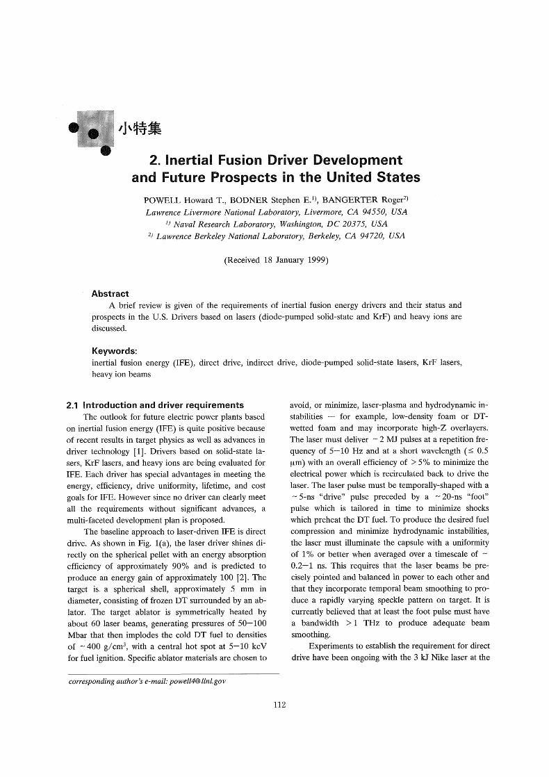
Presuming that NlF is successful in reaching its
goals in target ignition and gain, a program to develop
IFE drivers and chambers is now being proposed. A ti-
meline for the necessary IFE developments adopted by
consensus of leaders in the U.S. inertial fusion com-
munity is shown in Fig. 2. This timeline includes an
initial four-year proof-of-principle phase I in which the
technology of average-power laser drivers based on
both solid-state and KrF Iaser technology and heavy ion
technology are developed. Depending on the success of
these rep-rated driver developments, one or more of
the driver options would proceed to an Integrated Re-
search Experiment (IRE) in which a several kilojoule
driver is coupled with a fusion target at the required
5-10 Hz and at a driver efficiency of greater than 5"/o
as needed in a fusion power plant. A presumption in
this scenario is that the IRE driver would incorporate
all the necessary features of an IFE beamline to allow
confidence in the construction of a full plant-scale
driver in the next step. For both lasers and heavy ions,
the size of the IRE will be large enough that the cost
for the Phase 11 Engineering Test Facility (ETF) could
be accurately projected. For lasers the plan is to de-
velop and optimize one complete laser beam line, or
fraction of a beam line, that could be used directly in a
power plant. It could then be duplicated in parallel to
produce the needed total driver energy. While one
could also follow this parallel approach with ions, it
does not lead to an optimal accelerator in terms of effi-
ciency and cost. If the ion driver IRE is successful, it
Fig. 2
Investment
Economic (or no-go!)
Total project cost $3B.
Total project cost $2B.
$80M -1 20M/yr
$35-45M/yr
Decision Year
2002
Decision Criteria
The Demo has demonstrated the basis for economic, environmenta] I y-
benign IPE. Energy investors are convinced to go for large-scale commercial ex pansion
ETF has demonstrated the scientific and
technological feasibility of IFE and
has qualified the energy technology for the Demo
The design basis of the ETF has been sucessfull y
established from demonstration of !RE prototype driver(s)
and chamber technologies, together with the results from NIF
The driver-chamber design for the IRE(S) has been sucessfully established from parallel driver
research, 2&3-D target designs and chamber design protot ypes
A cost effective IFE driver and power plant development plan developed by looking backward from the ultimate goal.
Various decision points and development stages are noted.
ll4
'J'4~~i~ 2 . Inertial Fusion Driver Development and Future Prospects in the United States
would be more appropriate to add acceleration modules in series to produce the needed energy. A final
step in this scenario is the construction of a full test re-
actor with the optimum driver incorporating all the fea-
tures necessary for commercial electric power produc-
tion.
For inertial fusion, it is possible to simultaneously
evaluate the scientific, engineering, and economic feasi-
bilities at a relatively low cost. This is possible because
the different components - driver, chamber, pellet fac-
tory - are physically separate and can be developed
independently. In addition, a laser driver consists of
- 100 parallel and identical beam lines. Only one beam
line needs to be developed initially. And finally, the
inertial fusion program can take advantage of the in-
vestments by the defense communities in large glass
facilities, in target design capability, and in target inter-
action experiments.
2.2 Solid State Laser Drivers
Solid-state laser drivers operate in the ehergy stor-
age mode in which a relatively long optical pump pulse
( - 0.1-1 ms) is used to accumulate energy in the
upper laser level followed by a short energy extraction
pulse ( - 1-10 ns) which, after beam conditioning, is
used to drive the fusion target. Flashlamp-pumped
Nd:glass lasers [6] are the classical form of such an
energy storage system and provide the foundation for
future designs. In large aperture ( ~ 40 cm) Nd:glass
systems, Brewster mounted slabs are excited by flash-
lamps over a period of order the storage lifetime. The
aperture size and excitation period are limited by trans-
verse amplified spontaneous emission in the laser slabs.
The output energy of an amplifier chain is limited by
POWELL, BODNER 4~
the beam size and optical damage limits of the output
optics. The output power is limited by nonlinear self-
focusing in the laser chain (causing growth of beam
modulation) or possibly by Brillouin or Raman scatter-
ing in the optical components or propagation path.
Finally the output is converted to the second or third
harmonic in phase-matched frequency conversion crys-
tals, (KDP and KD*P are most commonly used) and
focused onto the target.
Modern Nd:glass laser systems such as Beamlet,
and now the National lgnition Facility employ con-
siderable sophistication in this overall design. This
sophistication is used to provide optimized target irradi-
ation parameters, to minimize cost, and to maximize
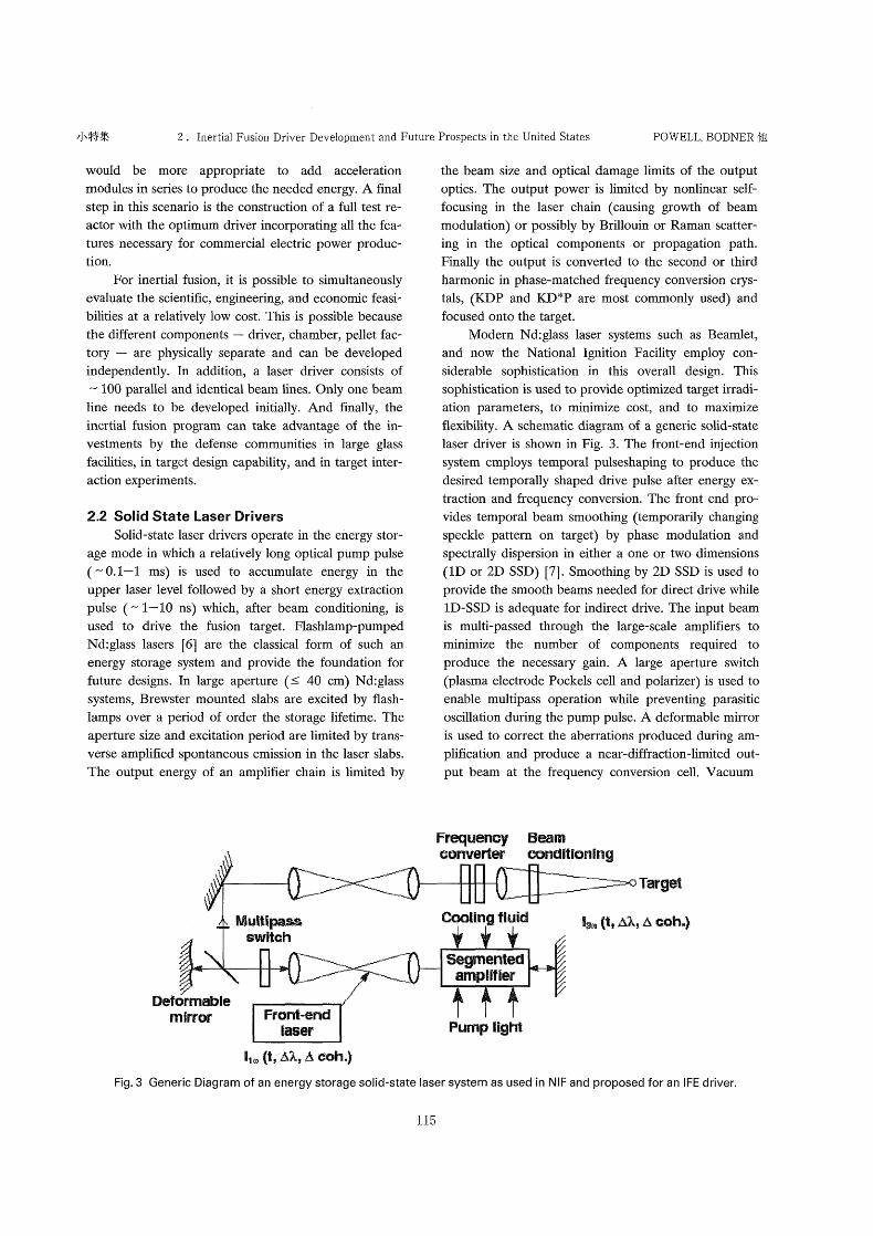
flexibility. A schematic diagram of a generic solid-state
laser driver is shown in Fig. 3. The front-end injection
system employs temporal pulseshaping to produce the
desired temporally shaped drive pulse after energy ex-
traction and frequency conversion. The front end pro-
vides temporal beam smoothing (temporarily changing
speckle pattern on target) by phase modulation and
spectrally dispersion in either a one or two dimensions
(1D or 2D SSD) [7]. Smoothing by 2D SSD is used to
provide the smooth beams needed for direct drive while
ID-SSD is adequate for indirect drive. The input beam
is multi-passed through the large-scale amplifiers to
minimize the number of components required to produce the necessary gain. A Iarge aperture switch
(plasma electrode Pockels cell and polarizer) is used to
enable multipass operation while preventing parasitic
oscillation during the pump pulse. A deformable mirror
is used to correct the aberrations produced during am-
plification and produce a near-diffraction-limited out-
put beam at the frequency conversion cell. Vacuum
FFequeRey Beam converter eo~d ~ Eon~ng
Ta~get
Wuttipess switGh
CooEing t~u~d
Fig. 3
Segmented am pEifier
t~~:~ (t, A~. ~ A sQh.}
Deformabl e mirror Front*end
EaseF PUmp Eight l~~ (t, A~ A Coh )
Generic Diagram of an energy storage solid-state laser system as used in NIF and proposed for an IFE driver.
115

j~ ;~~ ・ f~~~-~~i;~~'~~A~i'~~~~*#1 1999~P 2 ~]
spatial filters are used in the multipass cavity and in
transport to the target chamber to "clean up" the beam
profile and to relay image the beam without diffraction.
After frequency conversion, a large-scale diffractive
optic is used to control the spatial profile of the beam
on target and possibly, as in NlF, to provide a small di-
agnostic sample of the output beam and to separate the
desired third harmonic beam from the residual first and
second harmonic beams. The National lgnition Facility,
employing all these sophistications and producing 1.8
MJ at the third harmonic, has margin and flexibility to
produce fusion ignition and gains of 10-20 according
to a range of sophisticated laser and target models.
For a solid-state laser to reach the efficiency, repe-
tition rate, cost, and lifetime required in a fusion power
plant driver, major changes are required in this design
while building on the overall concept. The flashlamps
must be replaced by laser diodes which operate at
greater than 50'/o efficiency into a narrow bandwidth.
New optical designs are required to efficiently channel
the light from the diodes into the laser material. The
laser medium must be actively cooled in a geometry
that still affords a large area beam as needed to
maximize the energy per laser aperture, again consistent
with the ASE Iimits of the amplification medium.
LLNL has taken the approach of direct turbulent gas
(He) cooling of the slab faces [8] still allowing for large
area beams, while workers at he Institute for laser En-
gineering at Osaka University [9] are currently investi-
gating zig-zag slab designs in which water cooling can
be directly applied to the slab faces. The laser medium
and thickness are chosen to allow the necessary repeti-
tion rate while producing manageable thermal aberra-
tions.
After an intensive evaluation of alternative gain
modes, LLNL has selected a Yb-doped crystal gain me-
dium which provides a longer storage time (1.0 ms ver-
sus 0.3 ms) than Nd, thereby minimizing the investment
in laser diodes necessary to produce the required stored
energy. A detailed system study [10] has shown that a
large fraction of the driver cost is for laser diodes even
at presumed cost of S0.07/peak watt compared to cur-
rent cost of S3/peak watt. Such crystals also provides
good thermal conductivity to easily enable the required
repetition rate. However, the Yb-doped crystal (S-
FAP, strontium fluorapatite) which produces high gain
also has a relatively limited spectral bandwidth allowing
only a tripled bandwidth of - 0.3 THZ Which may be
inadequate for direct drive targets. Alternative Yo-
doped crystals which provide broader bandwidth as
well as Nd:glass itself are being considered to meet the
requirements of direct drive. Such gain media require
operating at higher output fluence and if Nd:glass,
higher diode costs. Because such a DPSSL driver would
have 3000 subaperture beams, considerable flexibility is
also possible in the laser design. For example, "foot"
beams might be based on Nd:glass and converted to the
second rather than the third harmonic for greater band-
width ( - 2 THz) while the main drive beams might be
based on Yb-doped crystals.
A demonstration diode-pumped solid-state laser
driver called Mercury is now under construction at
LLNL. The goals of Mercury are to produce a 100-J
first harmonic beam operating at 10 Hz with an overall
efficiency of 10"/* in the year 2000. A Phase I develop-
ment plan for DPSSL's as indicated in Fig. 2 includes
demonstrating efficient frequency conversion and the
required temporal beam smoothing on Mercury, de-
veloping laser diode pump arrays and laser crystals at a
cost and size acceptable for the IRE, and investigating
system design issues on Mercury. In parallel, final op-
tics and chamber developments are required to prove
the viability of DPSSL's as IFE drivers. An IRE based
on a DPSSL driver would test the bundling of several
fundamental apertures at the ASE-limited building-
block size ( ;~ I kJ/aperture). The possibility of using
the kJ-class DPSSL envisioned for an IRE as a cham-
ber development facility which provides x-rays, neu-
trons, and debris studies is also under investigation
[1l].
2.3 KrF Laser Drivers
The 1992 Sombrero [12] reactor design study
showed that a few-megajoule KrF (krypton-fluoride)
gas laser with a directly-illuminated inertial fusion pellet
has the potential of providing electricity at 5.5 to 6.5
cents/kW-hr - close to future coal and fission plants.
Because the high-technology laser is physically sepa-
rated from the reactor chamber, most maintenance
procedures would not require access to the chamber,
This reactor study required that the pellet have an
energy gain (thermonuclear yield divided by laser en-
ergy input) of approximately 100. There are new target
designs proposed by NRL [2] that have the potential of
this energy gain, and that may be consistent with all of
the target physics constraints in laser-plasma insta-
bilities and hydrodynamic instabilities. The computer
model used for these target designs has been success-
fully compared with a variety of laser-target experi-
ments using the few-kilojoule KrF Iaser at NRL called
Nike.
The Sombrero reactor study also required that the
ll6

,i.4~~1~ 2 . Inertial Fusion Driver Development and Future Prospects in the United States POWELL, BODNER 4ti2
KrF Iaser driver have a repetition rate of 5-10 Hz, an
efficiency of 7.5*/*, a cost of S170/J, a durability of 108
shots, and a 90"/. availability. NRL has demonstrated
significant progress by showing that a few-kiloj oule KrF
laser can be made sufficiently reliable for laser-target
experiments. However Nike has only 5-10 shots per
day and 200 shots between routine maintenance, with
- I '/* efficiency and relatively high cost. Nonetheless
most of the areas that require laser development for a
fusion reactor have been partially demonstrated else-
where, and there appears to be technical paths to build
the necessary laser driver.
To directly implode a pellet to high density re-
quires highly uniform laser beams. The pellet shell has
to converge about a factor of 25 in radius, and the
acceleration is susceptible to the Rayleigh-Taylor insta-
bility. A major breakthrough was the invention of opti-
cal beam smoothing, and in particular a technique
called ISI [ 13] (Induced Spatial Incoherence). The Nike
KrF Iaser [ 14] with ISI has a flux nonuniformity at
focus of only 1"/. rms in a 4 ns pulse. When we overlap
40 of these beams, the nonuniformity drops to about
0.15"/*, excluding the short-wavelength beam-beam in-
terference. The ISI optical smoothing technique can
only be used effectively with a gas laser such as KrF, in
which there are negligible nonlinear optical effects in
the amplifiers. Solid state lasers have used another opti-
cal smoothing technique, called 2D-SSD, and have
achieved single-beam flux nonuniformities [15] of
8-10"/~. Efforts are underway to improve the unifor-
mity of solid state lasers.
To develop KrF for a fusion reactor, we propose
first a concept validation step. We would build a 400
Fig.4 The measured focal spot laser intensity with the NRL KrF Iaser is only 1'/. rms (4 ns pulse; excluding
tilt and curvature),
J/pulse amplifier, with 5 Hz operation. Such a facility
(named Electra) would be large enough to be techni-
cally convincing, yet small enough to be manageable.
The six components of the 400 J Iaser that will require
development are: the pulsed power driver, the electron
beam source, the pressure foil support structure, the
laser gas conditioning system, the laser front end, and
the laser optics. We have preliminary and partial solu-
tions to the various technical problems.
In addition there would be parallel laser develop-
ment efforts in deformable mirrors, improved large
aperture transmissive optics, optical high-reflectivity
coatings with a higher damage threshold, improved
laser pulse shaping capabilities, advanced laser kinetic
modeling, along with complete architectural studies to
guide all of the above. This initial effort could take as
little as 4-5 years.
If this Phase I concept-validation activity is suc-
cessful, the next step would be a scaling validation
(shown as the IRE in Fig. 2), in which one KrF Iaser
beam line would be scaled up to 30-50 kJ/pulse. In
parallel, the NlF would be used for an integrated dem-
onstration of direct drive implosions. The pellet perfor-
mance with this glass lasers likely will be inferior to that
of a KrF, because of inferior beam smoothing. Non-
etheless, it would provide a useful integrated test of the
pellet concept. If this scaling validation is successful, the
next step would be a few-megajoule Engineering Test
Facility, in which one would duplicate the laser beam
line developed in the previous step, along with a reactor
chamber and small scale pellet factory.
2.4 Heavy lon Drivers
Heavy ion accelerators are the third class of
drivers. The goal of the heavy ion fusion program is to
apply high energy and induction accelerator technology
to IFE power production. Heavy ions (A>80) at ion
kinetic energies of 1-10 GeV have an ion penetration
depth appropriate for inertial fusion targets. Multi-stage
accelerators can readily produce such energies. Several
types of accelerators are being developed. Radio fre-
quency (RF) Iinacs (followed by storage rings) and in-
duction linacs (without storage rings) are currently the
favored approaches. The differences between these two
approaches are comparable to the differences between
diode pumped solid state lasers and KrF Iasers. In the
mid 1980's, the U.S. Department of Energy made a de-
cision to focus its research on induction accelerators.
Europe and Japan have favored the RF approach. Con-
sequently, the worldwide program rather than the U.S.
program would show four drivers rather than three.
117
7'~ ;~7 ' ~;~~~i~~~:A~~ * ~~~ *~
1999~P 2 ~i
There are a number of reasons to consider acceler-
ators for inertial fusion applications. An IFE driver
must deliver I to 10 MJ of beam energy. The beams
must be focused to a radius of a few millimeters and ac-
curately aimed from a distance of several meters. The
focusing system must survive in a fusion environment.
The driver must be efficient, reliable, and durable. It
must have a high-pulse repetition rate and good envi-
ronmental characteristics. Based on accelerator experi-
ence, it should be relatively straightforward to achieve
most of these requirements. Existing proton and elec-
tron accelerators are comparable to power plant drivers
in terms of size, cost, total beam energy, focusing, aver-
age beam power, reliability, and durability. They can be
efficient and they can easily produce the needed pulse
repetition rates. Existing accelerators are good neigh-
bors, operating in or under cities, villages, and farms.
Since the beams are focused by magnetic fields, the
conductors that produce these fields can be shielded
from neutrons, gamma rays, and other fusion products.
This provides a plausible solution to the problem of de-
veloping focusing elements that can survive in the fu-
sion environment. However existing accelerators do not
produce the beam current required for fusion. Since fu-
sion targets require beam powers of 100-1,000 TW,
the accelerators must deliver 10 kA - I MA of beam
current. The primary scientific issue in adapting ac-
celerator technology to inertial fusion is to produce
these high beam currents while retaining the well estab-
lished ability of accelerators to deliver beams that can
be extremely well focus. In addition, accelerator cost, as
in all three driver options, is an important issue.
As noted above, induction accelerators are the
U.S. approach to heavy ion fusion. A simple linear in-
duction accelerator consists of a number of magnetic
cores surrounding the beam which are pulsed sequen-
tially as the beam passes through them. These cores act
as transformers in which the beam serves as the second-
ary winding. By using a sufficient number of cores, it is
possible to accelerate ions to high kinetic energy. For
fusion applications, it is not reasonable to accelerate the
required current in a single beam. Consequently, most
designs of fusion accelerators have 10 to 1,000 beams
threading common induction cores. Each beam has its
own focusing channel - usually an alternating gradient
(quadruple) channel similar to the channels used in ac-
celerators for high energy physics.
Induction accelerators also have a number of other
components : an array of ion sources, an electrostatic
injector (pre-accelerator) to accelerate the ions to a
kinetic energy of the order of I MeV ,before they enter
the main induction accelerator, beam compression
channels, and a focusing system to direct and focus the
beams onto the fusion target. Typical accelerator de-
signs carry a current that is approximately an order of
magnitude smaller than the current required by the tar-
get. Thus compression channels are required to amplify
the current to the desired value. This amplification is
accomplished by accelerating the tail of the beams to a
slightly higher velocity than the head of the beams. As
the beams pass through the compression channels, the
beams become shorter leading to current amplification.
There is also current amplification in the accelerator it-
self. The current produced by a single ion source is of
the order of I A. As the ion kinetic energy increases
from approximately I MeV at the inj ector to perhaps 4
GeV at the end of the accelerator, the ion velocity in-
creases by more that a factor of 60 Ieading to a corre-
sponding current amplification as the physical beam
length remains constant. One can also increase the cur-
rent amplification factor in the accelerator by com-
pressing the beam longitudinally as described above.
Some accelerator designs employ one additional method of current amplification. In this method several
(usually four) beams are combined transversely to pro-
duce a single beam having higher current. At the end of
the accelerator each beam typically carries more than
100 A of current.
Although many of the components and beam ma-
nipulations just described are used in existing accelera-
tors, the currents needed for fusion are unprecedented.
Thus it is necessary to demonstrate what we define as
high current operation. If beams are not confined in a
focusing channel they expand because of their space
charge forces and because of their internal temperature.
In most conventional accelerators, temperature is the
more important effect. In fusion accelerators, because
of the high current, space charge dominates. From this
point of view, the object of heavy-ion fusion driver re-
search is to study and demonstrate the physics of space-
charge-dominated beams.
Laser-driven fusion and heavy-ion research are
strongly coupled. Lasers are well suited to near-term
target physics experiments so there has been no need to
develop large accelerators for these purposes. Conse-
quently, 'the heavy ion fusion program has emphasized
theory, numerical simulation, and small-scaled experi-
ments to address the key issue of focusing high current
heavy ion beams. Scaled experiments addressing all sys-
tems and beam manipulations in a full-scale driver have
been completed or are nearing completion, e.g., injec-
tor experiments, a scaled focusing experiment that
118

.J'4~~{~ 2 . Inertial Fusion Driver Development and Future Prospects in the United States POWELL, BODNER 4~
produces millimeter focal spots, an experiment that
combines four beams transversely while retaining good
beam quality, compression experiments, and experi-
ments on beam bending. The MBE-4 (Multiple Beam
Experiment with Four Beams) at Lawrence Berkeley
National Laboratory is typical of the machines built for
the scaled experiments. These experiments explore the
correct physics in the sense that dimensionless quan-
tities such as the ratio of space charge effects to tem-
perature effects have the correct values for fusion. For
reasons of economy, the beam currents themselves are
usually two orders of magnitude lower than those re-
quired for a fusion driver. The injector experiments are
an exception. Present injectors produce one full-scale
(approximately I A) beam. The scaled experiments are
nearing completion. These experiments, in agreement
with theory and simulation, suggest that it will be
possible to achieve adequate focusing at the currents
required for fusion.
Since the scaled experiments are nearing comple-
tion, we are now in a position to begin the Phase I
heavy ion research illustrated in Fig. 5 . The goal of the
Phase I research is to enable the construction of an
IRE, that, together with the results from the NIF, will
lead to an ETF. The requirements on the IRE Iargely
determine the Phase I research program. For heavy ion
fusion, the IRE must complete our knowledge base re-
lating to high current beams, it must demonstrate focus-
ing onto a target, and it must validate expectations of
good beam-target coupling. Beam-target coupling for
ions is the main target physics issue that will not be ad-
dressed on the NlF. Consider first the question of high
beam current. The currents required for fusion are large
enough to have a substantial effect on the acceleration
cores and pulses. Specifically, high currents load the ac-
celeration circuitry lowering the acceleration voltage.
Under some circumstances, this beam loading can lead
to instabilities. In order to show that these instabilities
are sufficiently benign, it will be necessary for the IRE
to accelerate more than 100 A. To demonstrate adequ-
ate focusing, the ions must be accelerated to more than
100 MeV. To validate the beam-target coupling, the
beams must produce a high density plasma and the
beam plasma frequency must be comparable to the
beam plasma frequency in a full scale driver. These re-
quirements dictate a total beam energy of several kilo-
joules focused to an intensity of 3 TW/cm2 or more.
We estimate that an IRE with the parameters given
above will cost more than SIOO M. It is not be prudent
to build such a facility based on our current under-
standing of high current beams and it is highly desirable
to minimize the cost of such a facility. To improve our
understanding of high current beams and to minimize
cost, we have developed a Phase I plan with the follow-
ing tasks :
1) Complete the present scaled experiments.
2) Develop an end-to-end (ion source to target)
numerical simulation capability.
3) Increase the current in our beam physics ex-
periments from approximately I O mA to I A.
Small recircular experiments at LLNL and U.Md.
Multi ple
Beam lon Source and in jector
Ongoing driver scale
experiments at LBNL
Chamber experiments at UCB and UCLA
Acceleration with electric focusing
Low current ex periments done at LBNL
Acceleration with magnetic
focusing
Low-current experiments done at LLNL, U.Md., and GSI
Target experiments at Nova, PBFA,...
Target injection ex periments at LBNL
Matching hardware done, experiments
at LBNL
Beam combining nearly done at LBNL
Transport ex periments
at LBNL, SNLA, and NRL
Compression done at LBNL, Iongitudinal
experiments planned at LLNL, U.Md.
Focusing ex periments at LBNL
Bending experiments in
progress at LLNL
Fig. 5 Schematic diagram of the elements of a heavy ion driver for IFE indicating where the critical questions are being ad-
dressed.
l 19
~~ ;~7 ・ ~~(~-~~Ar,'~~~~~~~~~-~'~ 1999~~ 2 ~I
4) Develop a multi-beam injector capable of de-
livering of the order of I OO A.
5) Reduce the cost of all major accelerator com-
ponents.
If these tasks are successfully completed, we will be in a
position to build a highly capable IRE for heavy ion fu-
sion experiments.
2.5 Conclusions Inertial fusion energy developments have now
reached a stage where they should be considered and
funded in parallel with magnetic fusion energy develop-
ments. There are two well-developed and promising
target approaches to IFE (direct and indirect drive) and
one advanced but unproven approach (fast ignitor) as
well as three candidate drivers (diode-pumped solid-
state lasers, KrF Iasers, and heavy ions). An orderly
program of development and down-selection is pro-
posed. To practically realize an IFE power source, con-
siderable more effort is needed in chamber and power
plant integration technologies as well as driver develop-
ments. The U.S. magnetic and inertial fusion energy
communities are now working more closely together to
solve the difficult problems that both communities face.
Acknowledgements The authors are grateful to our many colleagues in
the worldwide IFE community and particularly to E.
Michael Campbell, Ieader of the Laser Directorate at
LLNL, for his contributions. Work at Lawrence Liver-
more National Laboratory was supported by the U.S.
Department of Energy under contract W-7405-ENG-
48. The work at the Naval Research Laboratory was
supported through an interagency agreement with the
U.S. Department of Energy, and by the Office of Naval
Research. The work at the Lawrence Berkeley National
Laboratory was supported by the U.S. Department of
Energy, Energy Research Programs.
References [1] Energy from Inertial Fusion (Editor: W.J. Hogan)
International Atomic Energy Agency, Vienna
(1995).
[2] S.E. Bodner et al., Phys. Plasmas 5, 1901 (1998).
[3] D.A. Callahan-Miller and M. Tabak, submitted to
Nuclear Fusion.
[4] J.D. Lindl. Inertial Confinement Fusion, the Quest
for lgnition and Energy Gain Using Indirect Drive
(Springer-Verlag New York, Inc., 1998).
[5] M. Tabak et al., Phys. Plasmas 1, 1626 (1994).
[6] For many papers on solid-state laser technology
for inertial fusion including the NlF, see Proceed-
ings of First Annual Conference on Solid State
Lasers for Application to Inertial Confinement
Fusion, (Editors: Michel Andr6 and Howard T.
Powell), SPIE 2633 (1995); Proceedings of Sec-
ond Annual International Conference on Solid
State Lasers for Application to Inertial Confine-
ment Fusion (Editor: Michel L. Andr6), SPIE
3047, 1997.
[7] S. Skupsky et al., J. Appl. Phys. 66, 3456 (1989).
[8] S.B. Sutton and G.F. Albrecht, J. Appl. Phys. 69,
1183 (1991).
[9] S. Nakai, ILE Osaka University, private communi-
cation.
[10] C.D. Orth, S.A. Payne and W.F. Krupke, Nucl.
Fusion 36, 75 (1996).
[ 1 1] L.J. Perkins, LLNL, private communication.
[12] I.V. Sviatoslavsky et al., Fusion Technol. 21, 1470
(1992).
[13] R.H. Lehmberg and S.P. Obenschain, Optics
Comm. 46, 27 (1983).
[14] S.P. Obenschain et al., Phys. Plasmas 3, 2098
(1996).
[15] W. Seka, University of Rochester, private com-
munications.
120