Embed Size (px)
Citation preview
INFANT INCUBUTOR WITH
TEMPERATURE&HUMIDITY CONTROL
SYSTEM
GRADUATION PROJECT SUBMITTED TO THE
ENGINEERING FACULTY
OF
NEAR EAST UNIVERSITY
by
SEMA SOYTÜRK
SÜMEYYE BOYACI
BIOMEDICAL ENGINEERING
Supervisor: Assoc. Prof. Dr Terin ADALI
NICOSIA – 2014

I
THE INFANT INCUBUTOR WITH TEMPERATURE SENSOR AND HUMDITIY
SENSOR SYSTEM
Approval of Director of Graduate School of Applied Sciences
We certify this thesis is satisfactory for the award of the degree in
Biomedical Engineering
Examining Committee in Charg
Assoc. Prof. Dr Terin ADALI
Supervisor Department, Biomedical EngineeringDepartment,NEU
Assoc. Prof. Dr. Fa'eq RADWAN
Committee Chairman, Faculty of Engineering NEU
Dr. Ali IŞIN
Co-supervisor Biomedical Engineering Department,NEU

II
ACKNOWLEDGEMENT
We would like to express our gratitude to the people who have helped us in completing our
project successfully. We would like to our sincere thanks to them for their support to us at all
times.
Firstly, We would like to thank our supervisor Assoc. Prof. Dr Terin ADALI (Head of
Department of Biomedical Engineering) for her undue support and guidance given to us
during the course of our Project and for providing us with such as class infrastructures.
Then, We would like to thank Dr. Ali IŞIN for his ideas, suggestions, guidance, and support
to come up with this project. Special thanks for his constant motivation throughout this
project and this thesis.
And, We are very much owing to our parents for their moral support and encouragement to
achieve higher goals. We have no words to express our gratitude and we are very thankful to
our parents who have shown us this world and for every support they gave us.
Finally, We would like to thank all our friends for the help and criticism during our project
period…

III
ABSTRACT
Control of the parameters which have close values as the uterus such as temperature, humidity
and oxygen is very precious to health of the babies who are born premature or with other
problems. Even if this environment is simulated the uterus theoretic it is not possible at all in
practical.
In this study, nurse is asked to enter appropriate set values to keep temperature, humidity and
oxygen parameters at optimum level for babies. The set values taken from the user are
compared to the dates taken from sensors periodically, thus case of alarm is controlled.
In the first and second chapter of the project, the importance of the incubator and what it
medically means are expressed. There are some informations about the micro controller
which was used in incubator control card in the second chapter. In the third chapter are there
technical information about humidity sensor and temperature sensor and also about one-wire
which the sensor communicates. The last chapters the trouble that we had while we were
working on this project and required alarm cases were mentioned.
Keywords: Temperature, Humidity, Oxygen

IV
ÖZET
Erken veya sorunlu doğan bebeklerin anne rahmindeki ortama benzeyen sıcaklık, nem ve
oksijen gibi önemli parametrelerin kontrolü bebeğin sağlığı açısından önem teşkil etmektedir.
Bu ortam teorikte anne rahmine benzetilse bile pratikte tamamen mümkün olamamaktadır.
Bu çalışmada sıcaklık, nem ve oksijen parametrelerini bebek açısından optimum düzeyde
tutabilmek için hemşireden uygun set değerinin girilmesi istenilmektedir. Kullanıcıdan alınan
set değeri periyodik olarak sensörlerden alınan bilgiler ile karşılaştırılarak alarm durumları
kontrol edilmektedir.
Projenin ilk ve ikinci bölümünde küvözün önemi ve tıbbi açıdan ne anlama geldiği ifade
edilmektedir. Üçüncü bölümünde ise küvöz kontrol kartında kullanılan mikrodenetleyici
hakkında bilgiler verilmiştir.Dördüncü bölümünde sıcaklık sensörü ve nem sensörüyle ilgili
teknik bilgiler bulunmaktadır. Ayrıca sensörün haberleştiği one-wire hakkında bilgiler
mevcuttur.Son bölümde projeyi gerçekleştirirken çektiğimiz zorluklar ve gerekli alarm
durumlarından bahsedilmiştir.
Anahtar Kelimeler : Sıcaklık, Nem, Oksijen
1
THE INFANT INCUBUTOR WITH TEMPERATURE SENSOR AND HUMDITIY
SENSOR SYSTEM
Approval of Director of Graduate School of Applied Sciences
We certify this thesis is satisfactory for the award of the degree in
Biomedical Engineering
Examining Committee in Charg
Assoc. Prof. Dr Terin ADALI
Supervisor Department, Biomedical EngineeringDepartment,NEU
Assoc. Prof. Dr. Fa'eq RADWAN
Committee Chairman, Faculty of Engineering NEU
Dr. Ali IŞIN
Co-supervisor Biomedical Engineering Department,NEU

2
ACKNOWLEDGEMENT
We would like to express our gratitude to the people who have helped us in completing our
project successfully. We would like to our sincere thanks to them for their support to us at all
times.
Firstly, We would like to thank our supervisor Assoc. Prof. Dr Terin ADALI (Head of
Department of Biomedical Engineering) for her undue support and guidance given to us
during the course of our Project and for providing us with such as class infrastructures.
Then, We would like to thank Dr. Ali IŞIN for his ideas, suggestions, guidance, and support
to come up with this project. Special thanks for his constant motivation throughout this
project and this thesis.
And, We are very much owing to our parents for their moral support and encouragement to
achieve higher goals. We have no words to express our gratitude and we are very thankful to
our parents who have shown us this world and for every support they gave us.
Finally, We would like to thank all our friends for the help and criticism during our project
period…

3
ABSTRACT
Control of the parameters which have close values as the uterus such as temperature, humidity
and oxygen is very precious to health of the babies who are born premature or with other
problems. Even if this environment is simulated the uterus theoretic it is not possible at all in
practical.
In this study, nurse is asked to enter appropriate set values to keep temperature, humidity and
oxygen parameters at optimum level for babies. The set values taken from the user are
compared to the dates taken from sensors periodically, thus case of alarm is controlled.
In the first and second chapter of the project, the importance of the incubator and what it
medically means are expressed. There are some informations about the micro controller
which was used in incubator control card in the second chapter. In the third chapter are there
technical information about humidity sensor and temperature sensor and also about one-wire
which the sensor communicates. The last chapters the trouble that we had while we were
working on this project and required alarm cases were mentioned.
Keywords: Temperature, Humidity, Oxygen

4
ÖZET
Erken veya sorunlu doğan bebeklerin anne rahmindeki ortama benzeyen sıcaklık, nem ve
oksijen gibi önemli parametrelerin kontrolü bebeğin sağlığı açısından önem teşkil etmektedir.
Bu ortam teorikte anne rahmine benzetilse bile pratikte tamamen mümkün olamamaktadır.
Bu çalışmada sıcaklık, nem ve oksijen parametrelerini bebek açısından optimum düzeyde
tutabilmek için hemşireden uygun set değerinin girilmesi istenilmektedir. Kullanıcıdan alınan
set değeri periyodik olarak sensörlerden alınan bilgiler ile karşılaştırılarak alarm durumları
kontrol edilmektedir.
Projenin ilk ve ikinci bölümünde küvözün önemi ve tıbbi açıdan ne anlama geldiği ifade
edilmektedir. Üçüncü bölümünde ise küvöz kontrol kartında kullanılan mikrodenetleyici
hakkında bilgiler verilmiştir.Dördüncü bölümünde sıcaklık sensörü ve nem sensörüyle ilgili
teknik bilgiler bulunmaktadır. Ayrıca sensörün haberleştiği one-wire hakkında bilgiler
mevcuttur.Son bölümde projeyi gerçekleştirirken çektiğimiz zorluklar ve gerekli alarm
durumlarından bahsedilmiştir.
Anahtar Kelimeler : Sıcaklık, Nem, Oksijen

5
CONTENTS
ABBREVITIONS.................................................................................................................................... 8
INTRODUCTION................................................................................................................................... 9
CHAPTER 1 : INFANT INCUBUTOR............................................................................................... 11
1.1. Definiton Of Infant ..................................................................................................................... 11
1.2. What is The Infant Incubator?................................................................................................... 11
1.3. Importance of Infant Incubator.................................................................................................. 12
CHAPTER 2: DESIGN GOAL ............................................................................................................. 13
2.1. OVERVIEW .................................................................................................................................. 13
2.2 PROBLEM STATEMENT ................................................................................................................ 13
2.3 OBJECTIVE.................................................................................................................................... 13
2.4 STEPS ........................................................................................................................................... 13
CHAPTER 3: TEMPERATURE AND HUMIDITY CONTROL SYSTEM ....................................... 14
3.1. THE IMPORTANCE OF TEMPERATURE FOR BABIES .................................................................... 14
3.1.1. DESIGN, DEVELOPMENT AND PERFORMANCE....................................................... 15
3.1.2. Simple ON-OFF Control System ........................................................................................ 16
3.1.3 Combined Enhanced Temperature Control System ............................................................. 16
3.2. HUMIDITY CONTROL SYSTEM..................................................................................................... 17
3.2.1. Overview ............................................................................................................................. 17
3.2.2 Background .......................................................................................................................... 18
3.2.3. Aims .................................................................................................................................... 18
3.2.4. PROSS................................................................................................................................. 18
CHAPTER 4: [SHT11] Humidity Sensor and [DS18B20] Temperature Sensor .............................. 18
4.1 [SHT11] Humidity Sensor............................................................................................................ 18
4.1.1. Features ............................................................................................................................... 19
4.1.2.Sensor Chip .......................................................................................................................... 19
4.1.3. Material Contents ................................................................................................................ 20

6
4.1.4. Connections ......................................................................................................................... 20
4.1.6. Membranes .......................................................................................................................... 21
4.1.7. All-Round Relative Humidity Sensor For Any Application ............................................... 21
4.1.8.Sensor Performance.............................................................................................................. 22
4.2. Temperature Sensor [DS18B20 ] ................................................................................................ 22
4.2.1. FEATURES......................................................................................................................... 23
4.2.2. PIN CONFIGURATIONS................................................................................................... 23
4.2.3 Pin Description ..................................................................................................................... 24
4.2.4 Operation—Alarm Signaling............................................................................................... 24
CHEAPTER 5: MICROPROCESSORS AND PIC16F877A ............................................................... 25
5.1. GENERAL..................................................................................................................................... 25
5.1.1. What Is A Microcomputer? ................................................................................................. 26
5.1.2.What is a Microprocessor? ................................................................................................... 26
5.1.3. What Is Insıde A Microprocessor? ...................................................................................... 27
5.1.4. What Are They Used For?................................................................................................... 28
5.1.5. Microcontroller Based Biomedical Instrument ................................................................... 29
5.2. PIC16F877A CONTROLLER .......................................................................................................... 30
5.2.1. Features ............................................................................................................................... 32
5.2.2. LED Experiment................................................................................................................. 32
5.2.3. Pinout Description ............................................................................................................... 34
Fig.16............................................................................................................................................. 34
5.2.4. Central Processor Unit (CPU) ............................................................................................. 34
5.2.5. Memory ............................................................................................................................... 35
CHEAPTER 6: PARTS OF PROJECT ................................................................................................ 37
6.1 7805 POSITIVE-VOLTAGE REGULATORS ...................................................................................... 37
6.1.1. Description/Ordering Information ....................................................................................... 37
6.1.2.Advantages ........................................................................................................................... 38

7
6.1.3. Disadvantages...................................................................................................................... 39
6.2. LCD DISPLAY ............................................................................................................................... 39
6.2.1. Introduction ......................................................................................................................... 39
6.2.2.Pin Description: .................................................................................................................... 40
6.3. BC547.......................................................................................................................................... 40
6.4 CAPACITOR .................................................................................................................................. 41
6.5. HEATING ELEMENT (BULB) ......................................................................................................... 42
6.5.1. Heat Lamp ........................................................................................................................... 42
6.6. TSC-112D3H (RLI)........................................................................................................................ 43
6.6.1.Features ................................................................................................................................ 43
6.7. BUZZER ....................................................................................................................................... 44
6.7.1. Piezoelectric ........................................................................................................................ 44
6.7.2. Features ............................................................................................................................... 44
6.7.3. Applications......................................................................................................................... 45
6.8.SWITCHES .................................................................................................................................... 45
6.9. ACRYLIC SHEET............................................................................................................................ 45
6.9.1. Features ............................................................................................................................... 46
CHAPTER 7: PROJECT PHASES ....................................................................................................... 47
7.1.Overview ..................................................................................................................................... 47
7.2.Circuit Operation Principle .......................................................................................................... 47
7.3. ALARM CONTROL SYSTEM.......................................................................................................... 51
Chapter 8: SOFTWARE....................................................................................................................... 51
CONCLUSIONS ................................................................................................................................... 61
REFERENCES ...................................................................................................................................... 62

8
ABBREVITIONS
RH: Relative Humidity
PWM: Pulse Width Modulation
TEWL: Transepidermal Water Loss
LCC: Leadless Chip Carrier
NV: Nonvolatile
CPU: Central Processing Unit
CRT: Cathode Ray Tube
RAMs: Random-Access Memories
ROMS: Read-Only Memories
BAN: Body Area Network
SFR: Special-Function Registers

9
LIST OF FIGURES
Fig.1: Wheatstone bridge……………………………………………………………………..11Fig.2: Simple ON-OFF Control System ……………………………………………………..11Fig.3: The block diagram of the control system ……………………………………………..11Fig.4: Drawing of SHT11 sensor packaging………………………………………………....14Fig.5: SHT11 module…………………………………………………………………….......15Fig.6: Top view of example of mounted SHT11……………………………………….…….16Fig.7: Side view of SF1…………………………………………………….....................…....16Fig.8: Sensor Performance …………………………………………………………….……..17Fig.9: PIN CONFIGURATIONS……………………………………………..........................19Fig.10: Pin Description ………………………………………………………………... ......19Fig.11: Architecture of Microprocessor……………………………….……………….……..23Fig.12: Microcontroller Based Biomedical Instrument………………………………….…...23Fig.13: Some Examples For uC-Based Biomed Devices / Applications…………………......25Fig 14-15: LED Experiment ……………………………………………………………........28Fig.16: Pinout Description…………………………………………………......................…..29Fig.17:CPU…………………………………………………………….……………….…….30Fig.18……………………………………………………………………………………..…..31Fig.19………………………………………………………………………………………………………………………….……….33Fig.20: Pin Diagram…………………………………………………………………..…...….35Fig.21…………………………………………………………………………………………35Fig .22…………………………………………………………………………………...........37Fig.23………………………………………………………………………………….……...38Fig.24…………………………………………………………………………………….…...39

10
INTRODUCTION
Of the four million babies worldwide who die in the first month of life, one million die on
their first day. Preterm birth is related, directly or indirectly, to at least 25 percent of neonatal
deaths, and low birth weight newborns are at the greatest risk.
Incubators provide prevent heat loss to significantly and warmth improve survival rates. The
use of air-heated incubators has been the standard method of providing a stable, thermal
environment for the newborn infant at risk.
Humidity and Temperature play an important part in our environment. Changes in
temperature and humidity can project is to control relative humidity, the heat of a given
environment such as baby incubator.
Temperature regulation is one of the most important factors affecting. Infants typically lose
heat to their environment in four different ways: through convection, conduction, evaporation,
radiation. Premature infants, as compared to term infants, are at an even greater disadvantage
in temperature maintenance, because of the larger skin surface area to body mass ratio,
decreased subcutaneous fat. Hence, the normal surge in metabolic rate that occurs after birth
is reduced in preterm infants, resulting in limited heat production.
A microcontroller is used to control the temperature in a baby incubator. The temperature had
to be kept constant at 36.9 C as in mother’s womb. The system will function as stated in the
programming code of microcontroller in order to keep the temperature stable. A simple
temperature controller which has least complex circuitry has to be designed so that it saves
space and be more reliable for an incubator.
Present design which uses microprocessor as main controller in digital signal processing
combined with complex combinational logic circuit are redundant and needs to be improved
in the sense of functionality. Therefore, the replacement of microcontroller with an Aurduino
microcontroller is prudent action due to its efficiency, reliability especially in an incubator.

11
CHAPTER 1 : INFANT INCUBUTOR
1.1. Definiton Of Infant
A premature infant is a baby born before 37 completed weeks of gestation so; more than 3
weeks before the due date. Premature infants are at greater risk for short and long term
complications, impediments and including disabilities in growth and mental development.
1.2. What is The Infant Incubator?
Infant incubator is a biomedical device which provides humidity, warmth, and oxygen all in a
controlled environment as needed by the new born. You can consider as therapy device.
A baby incubator is an infant stimulating systems used for intensive care of the, premature,
newborn or sick baby. It provides spacious clean and sterile ambient conditions for the
promoters and newborns.
The our incubator environment provides stable and a homogeneous temperature a relative
humidity (RH) level and atmospheric gas concentration for intensive care of the premature
baby usually the controller used in the baby incubator is a microcontroller.

12
1.3. Importance of Infant Incubator
In baby incubator Humidity control is very important. And therefore we want to control the
Humidity according to our requirements. Humidity controller can be done by using an
electronic circuit, a microcontroller and a microprocessor.
Infant Incubutor Device
Temperature regulation is one of the most important factors affecting survival in newborn
infants. Infants typically lose heat to their environment in four different ways: through
convection, conduction, evaporation radiation. Incubators provide warmth and prevent heat
loss to significantly improve survival rates.

13
CHAPTER 2: DESIGN GOAL
2.1. OVERVIEW
This project is to design a temperature controller and a humidity controller to be used to
control the temperature and humidity status. A baby incubator is an infant stimulating system
used for intensive care of the newborn, premature or sick baby. It provides a clean and a safe
environment, which has fresh air, clean and sterile ambient conditions for the babies. Usually
the controller used in the baby incubator is a Microcontroller.
2.2 PROBLEM STATEMENT
Premature or babies are unable to keep themselves sufficiently warm. They are also very
weak and recipient to infections. An incubator is a special type of a coat which provides an
ideal environment for the baby. It tries to stimulate the conditions as inside the mother’s
womb.
2.3 OBJECTIVE
The main objective of our graduation project is to design a baby incubator with humidity
control and temperature control using a microcontroller (PIC16F877A) or Aurduino
Microprocessor, while monitoring the incubator temperature and humidity.
2.4 STEPS
• Search for information related to required environment, for example the size of the baby
Incubator, function of the incubator and any information related to our project.
•We searched for the equipment and materials required for our project.
• Build an incubator that is suitable and functions that the same as available incubator.
• Designed the PIC16F877A or Aurduino Microcontroller programming code according to
the specification of temperature and humidity control in C basic language software.
• Program the microprocessor is according to the specifications of the temperature and
humidity control system. Administer the circuit and build the model of incubator that is
suitable for our environment

14
CHAPTER 3: TEMPERATURE AND HUMIDITY CONTROL SYSTEM
3.1. THE IMPORTANCE OF TEMPERATURE FOR BABIES
Temperature plays an important part in our environment. Changes in temperature setting can
affect the behavior of human beings, plants and even materials such as semiconductors. Our
Graduation Project is to control the temperature of a given environment such as baby
incubator. Incubators provide warmth and prevent heat loss to significantly improve survival
rates. The use of air-heated incubators has been the standard method of providing a stable.
A microcontroller is used to control the temperature in a baby incubator. A simple
temperature controller which has least complex circuitry has to be designed so that it saves
space and be more reliable for an incubator. Present design which uses microprocessor as
main controller in digital signal processing combined with complex combinational logic
circuit are redundant and needs to be improved in the sense of functionality. Thus,replacement
of microcontroller with an microcontroller is prudent action due to its efficiency and
reliability especially in an incubator
Some (25%) of this deaths are caused due to complications of prematurity, most often due to
improper heat regulation, water loss and neonatal jaundice. An infant incubator provides
stable levels of temperature, relative humidity and oxygen concentration. Temperature control
system is the most important part of a baby incubator which has to be maintained around
37oC. In the present work we have designed and developed an enhanced temperature control
system incorporating a combination of Pulse Width Modulation (PWM) and simple ON-OFF
control system, where thermistors have been used as temperature sensors. The range of
variation of temperature against the set temperature (39C) has found to be 1oC which is
tolerance. A temperature setting monitor has been designed through a circuit network
incorporating a thermistor so that the voltage output is linearly related to the temperature. This
allowed the use of a simple milli voltmeter to display the temperature directly through
appropriate scaling. To ensure the safety of the premature an alarm circuit was designed
which provides sound alarms for personnel attention if the temperature goes beyond a
specified safe range, chosen here as 25oC – 39C.

15
3.1.1. DESIGN, DEVELOPMENT AND PERFORMANCE
The temperature of the baby incubator needs to be maintained at a constant level of 39oC. A
temperature indicator together with an alarm for accidental failures is also needed. This was
the main challenge of the present work. The performance of this combined system was
satisfactory. We have also designed a temperature indicator using a simple milli voltmeter by
linearizing the performance of thermistor in the range of temperature 25-39oC. This system
also incorporates high temperature (39oC) and low temperature (25oC) alarm for medical
attention in the case of accidental failure of the temperature regulation system.
Selection of an appropriate temperature sensor is important for effective control of
temperature in the incubator. Comparing the sensitivity and response time of available
temperature sensors as like t hermocouple thermistor, RTD in the range of temperature 25-
39oC along with accuracy, repeatability, term stability, linearity, self heating; thermistor is the
best choice in this case .
If the temperature falls below the set value appropriate amount of heat energy needs to be
supplied in the incubator to maintain the temperature at that level. This can be done by a
simple turn OFF and ON control system which will turn OFF the heater when the temperature
is below the set level and turn ON otherwise.,
Wheatstone bridge, as shown in Figure.1, rather than in a voltage divider circuit. Firstly a
balance is obtained through adjustments of the resistors in the other arms . The unbalanced
output voltage of the bridge in figure 1. was used to give a measure of the temperature
change. It is well known that this sensitivity is the greatest when R2 is almost equal to R4 .
So, the selection of the value of R1, R2 and R3 depends on the resistance of the thermistor. To
select the value of the resistance now we need to know the response of the thermistor that is to
be used with the change in temperature. Figure. 1 shows a graph of the resistance of a 4.7kΩ
thermistor with temperature. It can be seen that the resistance of the thermistor changes
between 4.4KΩ-3.2KΩ in the range of temperature between 31-39oC. The average resistance
in that range is 3.85KΩ. A resistor of this value is not practically available so we have used
4KΩ in the bridge circuit for R2.

16
Wheatstone bridge, as shown in Figure.1
3.1.2. Simple ON-OFF Control System
Block diagram of a simple ON-OFF control circuit is showed below in Fig. 2.
Fig.2
3.1.3 Combined Enhanced Temperature Control System
The block diagram of the control system is showned in Fig.3
Fig.3.
17
As long as the output of the Simple OFF-ON circuit is high the output of the AND gate
followed the PWM. So, the duty cycle of the heater or the amount of heat energy delivered is
controlled by the output of the PWM, that work off to a low value near 39oC. When the
temperature reaches the set temperature the output of the simple ON-OFF control circuit
becomes zero which forces the output of the AND gate to zero and overrides the PWM. So, it
finally shuts down the heater at the set temperature (39oC). However, the temperature
overshoots a little due to thermal inertia, but because of the reduced heating before switching
off the overshoot is much less than that encountered in a simple ON-OFF system described
before. The complete circuit diagram of this combined enhanced temperature control system
is shown in Fig.3.
3.2. HUMIDITY CONTROL SYSTEM
3.2.1. Overview
Humidification is the process of adding moisture over and above that which is already
naturally present in the environment. Humidity is a measure of the moisture content of the
air and can be measured as absolute humidity or relative humidity. It is this value which is of
most clinical significance to the preternatural infant. Relative humidity is high dependent
upon air temperature as the higher the temperature the greater the capacity of the air to hold
water vapor.
In this work we were developed a micro controlled system devoted to the newborn incubator,
in order to check the conditions of the environment provided to the premature babies a
humidity control system and software that carries out the reading of the sensors. With water
and humidity control, if it put up inside established band of comfort by standard. Two
microprocessed, similar newborn incubator were used, for the realization of the
measurements, being that one of the newborn incubator used distilled water and other one was
valued without water. The measures were collected to each 3 minutes during 98 hours. The
relative humidity inside premature incubator without water and with water but, without
humidity control, goes out from the band of comfort established by standard.

18
3.2.2 Background
NICU are now caring for more and more extremely immature, very low birth weight infants.
Evidence shows that when these infants are nursed naked in unhumidified incubators, they
are unable to maintain a normal body temperature. It is recommended that additional humidity
be used for all infants below 37 weeks gestation, and below 1.30 kg birth weight, during the
first week of life. Premature infants lose large amounts of heat due to the thin, poorly
developed epidermis and a relatively large surface area in relation to body weight. The
greatest source of heat loss is by evaporation. This occurs in the form of insensible water loss
and is known as transepidermal water loss. Individual studies have shown the importance of
high ambient humidity to prevent this water loss. Reduced significantly reduces electrolyte
abnormalities and difficulties with fluid balance.
3.2.3. Aims
Water loss reduce transepidermal
Improved temperature control
3.2.4. PROSS
Studies have been showed where humidification is used there is reduced transepidermal and
water loss improved temperature control reduced epidermal stripping and preservation of
skin tolerance reduced infection improved surviving and reduction in morbidity.
CHAPTER 4: [SHT11] Humidity Sensor and [DS18B20] Temperature Sensor
4.1 [SHT11] Humidity Sensor
SHT11 is Sensirion’s family of surface mountable relative temperature and humdirty sensors.
The sensors integrate sensor material signal processing on a fine foot print and provide a
fully calibrating digital output. A unique capacitive sensor elements are used to measure the

19
temperature while relative humidity is measured by a band-gap sensor. SHT11 is support in
a surface-mountable LCC which is approved for standard reflow soldering processesing.
Dimensions
Figure 4: Drawing of SHT11 sensor packaging, dimensions in mm (1mm = 0.039inch). Sensor label gives “11” for SHT11 as an
example. Contacts are assigned as follows: 1:GND, 2:DATA, 3:SCK, 4:VDD
4.1.1. Features
Energy of consumption:
Range of RH operating :
Range of T operating :
Time of RH response :
Output:
80uW (at 12bit, 3V, 1 measurement / s)
0 - 100% RH
-40 - +125°C (-40 - +257°F)
8 sec (tau63%)
digital (2-wire interface)
4.1.2.Sensor Chip
SHT11 V5 – for which this datasheet applies – features a version 4 Silicon sensor chip.
Besides the temperature and humidity sensors the chip contains an amplifier, A/D
converter, digital and memory interface. V5 sensors can be identified by the alpha-numeric
traceability code on the sensor cap – see example “A5Z” .

20
4.1.3. Material Contents
While the sensor is made of a CMOS chip the sensor housing consists of an LCP cap with
epoxy glob top on an FR4 substrate. The device is fully RoHS and WEEE compliant, thus it
is free of Pb, Cd, Hg, Cr(6+), PBB and PBDE.
4.1.4. Connections
The following diagram shows the connections required for the Sensirion SHT11 module.
Fig.5
4.1.5. Temperature Effects
Relative humidity reading strongly depends on temperature. Thus, it is essential to keep
humidity sensors at the same temperature as the air of which the relative humidity is to be
measured. In case of testing or qualification the reference sensor and test sensor must
showed equal temperature to allow for comparing humidity readings. Measures to reduce heat
transfer can be ventilation, reduction of copper layers between the SHT11 and the rest of the
PCB or millinga slit into the PCB around the sensor (see Figure 6).
If the SHT11 shares a PCB with electronic components that produce heat it should be

21
mounted in a way that prevents heat transfer or keeps it as low as possible.
Figure 6: Top view of example of mounted SHT1x with slits milled into PCB to minimize heat transfer
4.1.6. Membranes
SHT11 doesn’t contain a membrane at the sensor opening. But, a membrane may be add to
prevent dirt and droplets from entering the housing and to protect the sensor. Sensirion
recommends and supplies the SF1 filter cap for optimal IP54 protection Please compare
Figure 7. It will also reduce peak concentrations of chemical vapors.
Figure 7: Side view of SF1 filter cap mounted between PCB and housing wall. Volume below membrane is kept
minimal.
4.1.7. All-Round Relative Humidity Sensor For Any Application
SHT11 digital humidity and temperature sensor is the all-round version of the reflow solder
able humidity sensor series that combines decent accuracy at a competitive price. The
capacitive humidity sensor is available up to high volumes and every other sensor type of the
SHT11, it is fully calibrated and provides a digital output.

22
4.1.8.Sensor Performance
Fig.8
4.2. Temperature Sensor [DS18B20 ]
The DS18B20 digital thermometer provides 9-bit to 12-bit Celsius temperature measurements
and has an alarm function with nonvolatile user-programmable upper and lower trigger points.
The DS18B20 communicates over a 1-Wire bus that by definition requires only one data line
(and ground) for communication with a central microprocessor. It has an operating
temperature range of -55°C to +125°C and is accurate to ±0.5°C over the range of -10°C to

23
+85°C. In addition, the DS18B20 can derive power directly from the data line (“parasite
power”), eliminating the need for an external power supply. Each DS18B20 has a unique 64-
bit serial code, which allows multiple DS18B20s to function on the same 1-Wire bus. Thus, it
is simple to use one microprocessor to control many DS18B20s distributed over a large area.
Applications that can benefit from this feature include HVAC environmental controls,
temperature monitoring systems inside buildings, equipment, or machinery, and process
monitoring and control systems.
4.2.1. FEATURES
Unique 1-Wire® Interface Requires Only One Port Pin for Communication
Each Device has a Unique 64-Bit Serial Code Stored in an On-Board ROM
Multidrug Capability Simplifies Distributed Temperature-Sensing Applications
Requires No External Components
Can Be Powered from Data Line; Power Supply Range is 2.0V to 5.5V
Alarm Search Command Identifies and Addresses Devices Whose Temperature is
Outside Programmed Limits (Temperature Alarm Condition)
Available in 8-Pin SO (150 mils), 8-Pin sop, and 3-Pin TO-92 Packages
Software Compatible with the DS1822
Applications Include Thermally Sensitive System Industrial Systems, Thermostatic
Controls, Consumer Products, and Thermometers,
Thermometer Resolution is User Selectable from 8 to 12 Bits
Converts Temperature to 12-Bit Digital Word in 780ms (Max)
User-Definable Nonvolatile Alarm Settings
4.2.2. PIN CONFIGURATIONS

24
Fig.9
4.2.3 Pin Description
Fig.10
4.2.4 Operation—Alarm Signaling
After the DS18B20 performs a temperature conversion, the temperature value is compared to
the user-defined two’s complement alarm trigger values stored in the 1-byte TH and TL
registers . TH and TL can be accessed through bytes 2 and 3 of the scratchpad as explained in
the Memory section.
Only bits 11 through 4 of the temperature register are used in the TH and TL comparison since
TH and TL are 8-bit registers. If the measured temperature is lower than or equal to TL or
higher than or equal to TH, an alarm condition exists and an alarm flag is set inside the

25
DS18B20. This map is updated after every temperature measurement; therefore, if the alarm
condition goes away, the flag will be turned off after the next temperature conversion.
Any DS18B20s with a set alarm flag will respond to the command, so the master can
determine exactly which DS18B20s have experienced an alarm condition. If an alarm
condition exists and the TH or TL settings have changed, another temperature conversion
should be done to validate the alarm condition. The master device can check the alarm flag
status of all DS18B20s on the bus by issuing an Alarm Search command.
CHEAPTER 5: MICROPROCESSORS AND PIC16F877A
5.1. GENERAL
A microprocessor is one of the most exciting technological innovations in electronics since
the appearance of the transistor. This device hasn’t only set in the process of revolutionizing
the field of digital electronics, but it is also getting entry into almost human life.
Applications of microprocessors range from the very sophisticated process controllers and
supervisory control equipment to simple game machines and even toys. It is, therefore,
imperative for every engineering, specially electronics engineer, to know
about microprocessors. Every designer of electronic products needs to learn how to use
microprocessors. Even if he has no immediate plans to use a microprocessor, he should have
knowledge of the subject so that he can intelligently plan his future projects and can make
sound engineering judgements when the time comes.
Once he has understood signal of each component and its place in the system, he can go
deeper into the working details and design of individual components without difficulty.
The subject of microprocessors is overviewed here with the objective that a beginner gets
to know what a microprocessor is, what it can do, how it fits in a system and gets an overall
idea of the various components of such a system.

26
5.1.1. What Is A Microcomputer?
The microcomputer is simply a less powerful minicomputer. Microcomputers have smaller
instruction sets and are slower than mini computers, but then they are far less expensive and
smaller too. To an engineer with a hardware background and no computer experience, a
microcomputer will look like a sequential state machine that can functionally replace
thousands of random chips, logic , but occupies a much lesser space, costs much lesser and
the number of device interconnections being fewer in it, is much more reliable.
A microcomputer is primarily suited, because of its very low cost and very small size, to
dedicated applications. On the same grounds, the main computer is as a suitable as a general
purpose computer. Minicomputer finds applications in both areas.
5.1.2.What is a Microprocessor?
Microprocessors are important devices in our everyday machines called computers. Before
we start, we need to understand what microprocessors are and their suitable implementations.
Microprocessor is an electronic circuit that functions as the central processing unit (CPU) of a
computer, providing computational control. The microprocessor, is the brain of all computers
and many household and electronic devices . It comprises of three basic parts:
(a) Central Processing Unit (CPU)
It performs the necessary arithmetic and logic operations and controls the timing and general
operation of the complete system.
(b) Input/Output (I/O) Devices
Input devices are used for feeding data into the CPU, examples of these devices are
switches, analog-to-digital converters, card readers, keyboards, paper tape readers, disk etc.
The output devices are used for delivering the results of computations to the outside world;

27
examples are light emitting diodes, cathode ray tube (CRT) displays, digital-to-analog
converters,card and paper-tape punches, character printers, plotters, communication lines etc.
The output devices are used for delivering the results of computations to the outside world;
(c) Memory
It stores both the instructions to be executed (i.e., the program) and the data involved. It
usually consists of both RAMs (random-access memories) and ROMS (read-only memories).
A microprocessor is an integrated circuit designed to function as the CPU of amicrocomputer.
5.1.3. What Is Insıde A Microprocessor?
The microprocessor or CPU reads each instruction from the memory, decodes it and executes
it. It processes the data as required in the instructions. The data is retrieved from memory or
taken from an input device and the result of processing is stored in the memory or delivered to
an appropriate output device, all as per the instructions. The processing is in the form of
arithmetic and logical operations.
A typical microprocessor architecture is shown fig.11. The various functional units
are as follows:To perform all these functions, the µP (microprocessor) incorporates various
functionalunits in an appropriate manner. Such an internal structure or organizational
structure of µP,which determines how it operates, is known as its architecture.

28
Figure 11. Architecture of Microprocessor
5.1.4. What Are They Used For?
Like all good things, this powerful component is basically very simple. It is made by mixing
tested and high- quality "ingredients" (components) as per following receipt:
1. The simplest computer processor is used as the "brain" of the future system.
2. Depending on the taste of the manufacturer, a bit of memory, a few A/D
converters, timers, input/output lines etc. are added
3. All that is placed in some of the standard packages.
4. A simple software able to control it all and which everyone can easily learn
about has been developed.
On the basis of these rules, numerous types of microcontrollers were designed and they
quickly became man's invisible companion. Their incredible simplicity and flexibility
conquered us a long time ago and if you try to invent something about them, you should know
that you are probably late , someone before you has either done it or at least has tried to do it.

29
5.1.5. Microcontroller Based Biomedical Instrument
1. A computer is large in size and limits portability
2. A general purpose computer does a lot of things that are unnecessary for some dedicated
biomedical instruments
3. Several applications require the use of a dedicated instrument: portable (home
measurement devices) or otherwise (Ultrasound, X-RAY,MRI, CT, etc.)
• Portable systems require the use of a microprocessor
• Larger systems necessitate the design of a dedicated computer system (hard drive, display
monitor, elaborate controls)
Fig.12
Some Features / Advantages of Microcontrollers:
● They are small and flexible
● Data interchange using standard bus systems; -> various peripheral hardware accessible
● IDEs and toolchains for firmware programming
● Few external components and wires needed
● Low and ultra low power designs possible (-> PSoC, ASIC )
● Wide range of different uCs available (memory, I/O, speed, busses, A/Ds )
● Easy to use ( most of the time .. )
● Simulation and high level languages

30
Some Examples For Microporocessor Biomed Devices / Applications:
● Various sensors or meters: Blood Pressure, Body temperature, Blood Sugar Level, …
● Implants and prostetics
● Pacer makers
● Functional Electrostimulation
● Artificial Limbs and Orthesis
● Biosignal acquisition equipmentS
Fig.13
● Portable emergency equipment
● Sports medicine
● Patient monitoring
● Support of Communication for disabled persons
● Body Area Network / Wireless sensor networks
● Sensors and Actuators medical equipment Life-point defibrillator Spo2 Module
5.2. PIC16F877A CONTROLLER
The PIC16F887 is a product of Microchip. It features all the modules that modern
microcontrollers normally have. For its low price, wide range of application, high quality
and easy availability, it is an ideal solution in applications such as the control of different
processes in industry, measurement of different values etc. A list below includes only some
of its key features.

31
Available now exciting range of inexpensive controller boards, ideal for standard embedded
applications and incorporating into machinery, control systems and robots. PIC16F877
Controller board features the powerful Microchip PIC16F877 Microcontroller, one of the
most popular microcontrollers on the market. Combined into a easy to use and ready to run
board complete with all the necessary components for plugging directly into your system.
The PIC16F877 Microcontroller includes 8kb of internal flash Program Memory, together
with a large RAM area and an internal EEPROM. An 8-channel 10-bit A/D convertor is also
included within the microcontroller, making it ideal for real-time systems and monitoring
applications. All port connectors are brought out to standard headers for easy connect and
disconnect. In-Circuit program download is also provided, enabling the board to be easily
updated with new code and modified as required, without the need to remove the
microcontroller.
The PIC16F877 Controller is the ideal solution for use as a standard controller in many
applications. The small compact size combined with easy program updates and
modifications , make it ideal for use in machinery and control systems, such as alarms, card
readers, real-time monitoring applications and much more. This board is ideal as the brains
of your robot or at the center of your home-monitoring system. Save time and money, by
simply building your ancillary boards and monitoring circuits around this inexpensive and
easy to use controller.
All the necessary support components are included, together with a Power and Programming
LED for easy status indication. Plus a reset switch for program execution and a RS232
connection for data transfer to and from a standard RS232 port, available on most
computers.
In this section, properties of PIC16F877 microcontroller, CCS compiler, ICD-S, the
reference book “Embedded C programming and the microchip PIC” are briefly explained to
give a general idea; it may seem confusing for a first time reader who is not familiar to

32
microcontroller’s technology or C programming. However, as the functionality of the
components such as timers, A/D converters, I/O Ports are explained in detail in Section 3 as
they are being used in the experiments, the fundamental concepts would be better
understood and, the reader can flashback to this section to view the schematics and the
specifications.
PIC16F877 is one of the most commonly used microcontroller especially in automotive,
industrial, appliances and consumer applications. In Figure –14, the block diagram of the
PIC16F877 is illustrated.
The features of PIC16F877 are:
5.2.1. Features
Includes Powerful Microchip PIC16F877 Microcontroller with 8kb Internal Flash
Program Memory
Operating Speed at 10MHz
Direct In-Circuit Programming for Easy Program Updates
Up to 28 I/O points with easy to connect standard headers
RS232 Connection with MAX232
Internal EEPROM
8 Channel 10-bit A/D Convertor
One 16-bit Timer with Two 8-bit Timers
Power and Programming LED
Reset Button
Ideal as an Interchangeable Controller for Real-Time Systems
5.2.2. LED Experiment
The digital I/O and the timers will be discussed with this experiment. The program will count
from 0 to 255 and output the binary equivalent of this number to PortD every 2 seconds. The

33
digital I/O peripherals are discussed in detail in the next experiment “Dipswitch”. In this
experiment we will focus on the usage timers.Timers and counters are one of the most
commonly used perpheral in a microcontroller. They can be used to measure time periods,
speed and provide output signals in a specified rate. The PIC16F877 has 4 timers timer0,
timer1, timer2 and watch dog timer. Timer0 and timer2 are 8 bit timers and timer1 is a 16bit
timer. The inportant issue is to know when the counter reaches the maximum value (255 in 8
bit timers and 65,535 is 16bit timers) and rolls over.
The watch dog timer is a safety device. When an unepected event occurs, the watch dog timer
resets the microcontroller. In this experiment we will use the watch dog timer as our timer to
time the digital output.
Fig.14
Fig.15

34
5.2.3. Pinout Description
Most pins of the PIC16F887 microcontroller are multi-functional as seen in figure above. For
example, designator RA3/AN3/Vref+/C1IN+ for the fifth pin of the microcontroller indicates
that it has the following functions:
RA3 Port A third digital input/output
AN3 Third analog input
Vref+ Positive voltage reference
C1IN+ Comparator C1 positive input
Such pin functionality is very useful as it makes the microcontroller package more compact
without affecting its operation. These various pin functions cannot be used simultaneously,
but can be changed at any point during operation.
Fig.16
5.2.4. Central Processor Unit (CPU)
As any attempt to explain the operation of the CPU in detail would take us too far, we are not
going to do it at this stage. Anyway, it is important to point out that the CPU is manufactured
in RISC technology as this fact may be crucial when deciding which microcontroller to
use.RISC stands for Reduced Instruction Set Computer, which gives the PIC16F877 two great
advantages:

35
The CPU is capable of recognizing and executing only 35 simple instructions. By the
way, to program other microcontrollers in assembly language it is necessary to know
more than 200 instructions by heart.
The execution time is the same for almost all instructions, and lasts 4 clock cycles.
The clock frequency is stabilized by a quartz crystal. The exceptions to the rule are
jump and branch instructions the execution time of which is 2 clock cycles. It means
that if the microcontroller’s operating frequency is 20MHz, the execution time of each
instruction will be 200nS, i.e. the program will execute 5 million instructions per
second!
5.2.5. Memory
The PIC16F887 features three types of memory: ROM, RAM and EEPROM. Each deserves
to be separately discussed here due to their specific functions, features and organization.
Fig.17
ROM Memory
ROM memory is used to permanently save the program being executed. This is why it is often
called ‘program memory’. The PIC16F887 has 8Kb of ROM . Since the ROM memory is
made with FLASH technology, its contents can be changed by providing a special
programming voltage (13V).However, it is not necessary to explain it in detail as being

36
automatically performed by means of a special program on the PC and a simple electronic
device called the programmer.
Fig.18
EEPROM Memory
Similar to program memory, the contents of EEPROM is permanently saved, even when the
power goes off. However, unlike ROM, the contents of EEPROM can be changed during the
operation of the microcontroller. This is why this memory is perfect for permanently saving
some of the results created and used during the operation.
RAM Memory
This is the third and the most complex part of microcontroller memory. In this case, it consists
of two parts: general-purpose registers and special-function registers (SFR). All these
registers are divided in four memory banks to be explained later in the chapter.
Even though both groups of registers are cleared when power goes off and even though they
are manufactured in the same manner and act in a similar way, their functions do not have
many things in common.

37
CHEAPTER 6: PARTS OF PROJECT
Our Project comprises of this elements and equipments:
7805
LCD
Capacitor
BC547
Buzzer
Heat Lamp
Switches
RLI (TSC-112D3H)
Fan
6.1 7805 POSITIVE-VOLTAGE REGULATORS
6.1.1. Description/Ordering Information
This series of fixed-voltage integrated-circuit voltage regulators is designed for a wide range
of applications. These applications include on-card regulation for elimination of noise and
distribution problems associated with single-point regulation. . The internal current-limiting
and thermal-shutdown features of these regulators essentially make them immune to overload.
Each of these regulators can deliver up to 1.8 A of output current in addition to use as fixed-
voltage regulators, these devices can be used with external components to obtain adjustable
output voltages and currents, and also can be used as the power-pass element in precision
regulators.

38
Fig.19
6.1.2.Advantages
The 7805 series don’t require additional components to provide a constant, regulated
power of source, making them easy to use, as well as economical and efficient uses of
space. Other voltage regulators may require additional components to set the output
voltage or to assist in the regulation process. Some other designs may need substantial
engineering expertise to implement.
7805 series have built-in protection against a circuit drawing too much power. They
have protection against heating and short circuits, making them quite in most applications.
Fig.19

39
6.1.3. Disadvantages
The input voltage must always be higher than the output voltage by some minimum
amount.This can make these devices unsuitable for powering some devices from certain
types of power sources
As they are based on a linear regulator design, the input current required is always the
same as the output current. As the input voltage must always be higher than the output
voltage, this means that the total power are going into the 7805 will be more than the
output power provided. The extra input power is dissipated as well as heat.
6.2. LCD DISPLAY
6.2.1. Introduction
LCD is an electronic screen module and range of applications. A 16x2 LCD display is very
basic module and is very commonly used in various devices and circuits. These modules are
preferred over seven segments and other multi segment LEDs. The reasons being: LCDs are
economical; easily programmable; have no limitation of displaying special & even custom
characters, animations.
A 16x2 LCD means it can display 16 characters per line and there are 2 such lines. In this
LCD each character is displayed in 5x7 pixel matrix. This LCD has two registers, namely,
Command and Data.The command register stores the command instructions given to the
LCD. The data is the ASCII value of the character to be displayed on the LCD. Click to learn
more about internal structure of a LCD.A command is an instruction given to LCD to do a
predefined task like initializing it, clearing its screen, setting the cursor position, controlling
display etc. The data register stores the data to be displayed on the LCD.

40
Pin Diagram:
Fig.20
Alphanumeric displays are used in a wide range of applications, including palmtop
computers, word processors, photocopiers, point of sale terminals, medical instruments,
cellular phones, etc. The 16 x 2 intelligent alphanumeric dot matrix display is capable of
displaying 220 different characters and symbols. Booklet provides all the technical
specifications for connecting the unit, which requires a single power supply.
6.2.2.Pin Description:
Fig.21
6.3. BC547
BC547 is an NPN bi-polar junction transistor. A transistor, stands for transfer of resistance, is
commonly used to amplify current. The current at its base controls a larger current at collector

41
& emitter terminals.BC547 is mainly used for amplification and switching purposes. It has a
maximum current gain of 800.
The transistor terminals require a fixed DC voltage to operate in the desired region of its
characteristic curves. This is known as the biasing. For amplification applications, the
transistor is biased such that it is partly on for all input conditions. The input signal at base is
amplified and taken at the emitter. BC547 is used in common emitter configuration for
amplifiers. The voltage divider is the commonly used biasing mode. For switching
applications, transistor is biased so that it remains fully on if there is a signal at its base. In the
absence of base signal, it gets completely off.
6.4 CAPACITOR
A capacitor (originally known as a condenser) is a passive two-terminal electrical
component used to store energy electro-statically in an electric field. The forms of practical
capacitors vary widely, but all contain at least two electrical conductors separated by
a dielectric. The conductors can be thin films of metal, aluminum foil or disks, etc. The non-
conducting dielectric acts to increase the capacitor's charge capacity. A
dielectric can be glass, ceramic, film, air, paper. Capacitors are widely used as parts
of electrical circuits in many common electrical devices.

42
Fig.22
A capacitor consists of two conductors separated by a non-conductive region. The non-
conductive region is called the dielectric. A capacitor is assumed to be self-contained and
isolated, with no net electric charge and no influence from any external electric field. The
dielectric is just an electrical insulator. Examples of dielectric media are glass, air and
a semiconductor depletion region chemically identical to the conductors.
6.5. HEATING ELEMENT (BULB)
A heating element converts electricity into heat through the process of resistive or Joule
heating. Electric current passing through the element encounters resistance, resulting in
heating of the element. This process is independent of the direction of current flow.
6.5.1. Heat Lamp
Model incandescent lamp, with resistance depending on temperature. The Lamp model is an
incandescent lamp, the key characteristic of which is that the resistance increases as the
filament warms up.
A chrome bulb guard is also provided and easily snaps onto the lamp housing after the bulb is
installed. Standard is 220V socket. The heat lamp is table mounted with an adjustable swing
arm providing for easy adjustment of radiant heat to specimen. It has a feedback sensor to

43
prevent overheating when used series of controllers. The bumb is supplied with a 100W heat
lamp bulb and a built in reflector.
6.6. TSC-112D3H (RLI)
Power Relay; Series:TSC; Relay Type:Miniature; Contacts:SPDT; Relay Mounting:PC
Board; Carry Current:1A; Leaded Process Compatible:Yes Coil Voltage VDC Nom:12V;
Coil Resistance:480ohm; No. of Poles:1;RoHS Compliant: Yes
Fig.23
6.6.1.Features
• Low coil power requirement for IC.
• Terminals arrangement on grid pattern.
• 1 Form C contact arrangement.
• Designed for thermostat, modem,video recording and security applications.
44
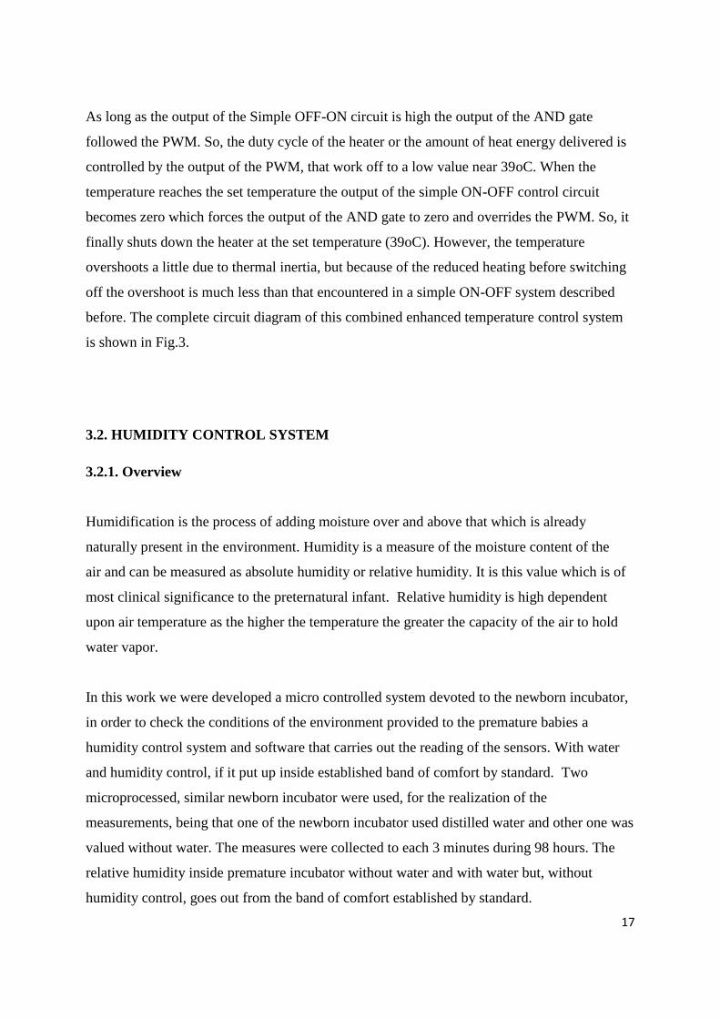
6.7. BUZZER
A buzzer is an audio device, which may be mechanical, piezoelectric or electromechanical.
Typical uses of buzzers and beepers includetimers , alarm devices, and confirmation of user
input such as a mouse click.
Fig.24
6.7.1. Piezoelectric
A piezoelectric element may be driven by an oscillating electronic circuit or other audio
source, driven with a piezoelectric audio amplifier. Sounds commonly used to indicate that a
button has been pressed are a click, a ring or a beep.
6.7.2. Features
1. No contacts hence, no noise and highly reliable.
2. Low power consumption.

45
6.7.3. Applications
• Telephone ringers.
• Various office equipment as like , printers and keyboards.
• Various home applications as like microwave ovens.
• Sound of various audio equipment.
6.8.SWITCHES
THE switch is an electrical component while can break an electrical circuit, the current or
diverting it from one conductor to another. Buttons, makes setting of temperature and
humidity set value in circuit.
6.9. ACRYLIC SHEET
The Acrylic Sheet is a material with unique physical properties. It weighs half as much as the
finest optical glass, that is equal to it inclarity and is up to 18 times more impact resistant. It
sheet is made in over 250 colors. It can transmit ultraviolet light or filter it out as required.
It’s light and energy transmission properties architects find it’s sheet ideal for skylights,
screens, sun, fascia panels and dome structures.
46
6.9.1. Features
Light Transmission
Colorless Cast acrylic sheet has a light transmittance of 92%. It is clearer than window glass
and will not turn yellow. It is also available in a large variety of transparent
and translucent colors.
UV Light Resistance
Clear acrylic sheet resists ultraviolet light concentrations. The acrylic sheet has a ten year
limited warranty against yellowing and loss of light transmission.
Optical Clarity
Clearer than glass. It isn’t yellow after prolonged sun exposure Acrylic sheets have excellent
light transmission..
Weather Resistance
Cold, despite heat,sunlight, and humidity acrylic sheet maintains its original appearance and
color.
Safety
Shatter-resistant, earthquake reliable.
Light Weight
Its strength and durability, acrylic sheet is only half the weight of glass. The two
compartments compartment A and compartment B are separated.. A detailed description of
the two compartments are given following..
Expansion and Contraction
Cast acrylic sheet responds to temperature , humidity changes by expanding or contracting at
a far greater rate than glass.

47
Flexibility
It’s much more flexible than glass , many other building materials.
Chemical Resistance
It’s excellent resistance to attack by many chemicals. It is affected, varying degrees, by
toluene, benzene, carbon tetrachloride, ethyl and methyl alcohol, lacquer thinners, ethers,
ketones.
Electrical Properties
It is an excellent insulator. Its surface resistivity is higher than that of most plastics.
CHAPTER 7: PROJECT PHASES
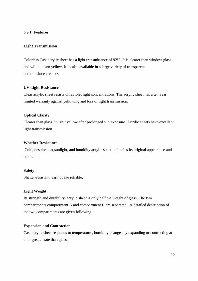
7.1.Overview
We used the PROTEUS (ISIS) program for temperature and humidity circuit. After making
the first drawing Proteus, we have observed that our circuit works. After receiving the
printing scheme ,were printed on a plaque with ironing method. After completing the wash
plate and drilling operations, was fitted circuit elements by the method of soldering. We
conclude that the circuit works by connecting 12V.
7.2.Circuit Operation Principle
Our circuit is opened by resetting itself. Switches in the circuit can be controlled with the
temperature and humidity values. Temperature settings are set between 25 and 39 degrees.
humidity between % 90 and % 30 is set. There are (+-3) tolerance values in our
environment. 2 bulbs are used as heaters.
Circuit Diagram

48
>>>>> In the pictures below ;you can see the stages of our project.<<<<<<
Plaques are washing after removing acidic water.
49
Proteus program, view our circuit printed circuit.
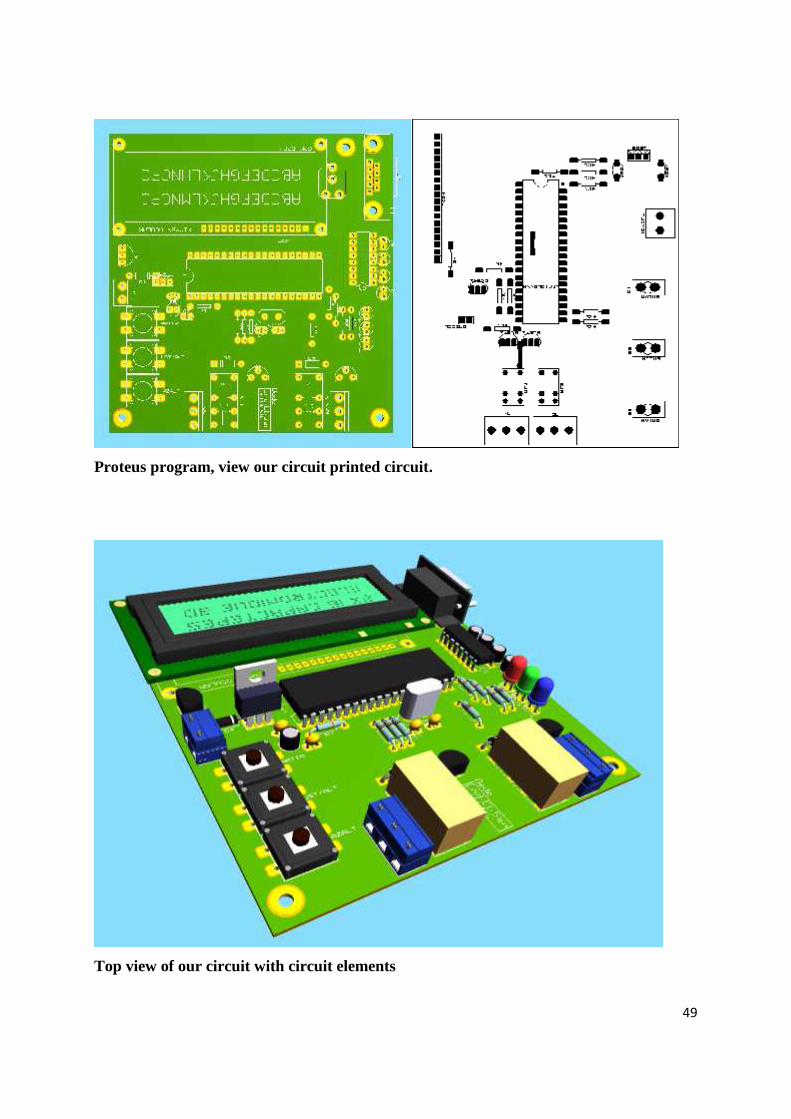
Top view of our circuit with circuit elements

50
The Final Version Of Our Project
51
7.3. ALARM CONTROL SYSTEM
The alarm circuit is safety measure to ensure the safety of the premature , by calling the
attention of medical staff, however the system fails, or crossed the set control. We have been
designed an alarm control circuit which will provide high temperature indication when the
temperature of the incubator exceeds 39⁰C. It also provides low temperature indication when
temperature of incubator is below 25⁰C and in both case it will produce loud sound from the
speaker for medical attention.
Chapter 8: SOFTWARE
'****************************************************************
'* Name : SICAKLIK NEM KONTROL.LCD.BAS *
'* Author : *
'* Notice : Copyright (c) 2014 [select VIEW...EDITOR OPTIONS] *
'* All Rights Reserved : *
'* Date : 22.02.2014 *
'* Version : 1.0 *
'* Notes : *
'* *
'************************************************************
' This program wrote for PIC 16F877A
'************************************************************
include "modedefs.bas"
'------------------------------------------------------------------
' Define LCD registers and bits
'------------------------------------------------------------------
Define LCD_DREG PORTB
Define LCD_DBIT 2
Define LCD_RSREG PORTB
Define LCD_RSBIT 0

52
Define LCD_RWREG PORTB
Define LCD_RWBIT 1
Define LCD_EREG PORTB
Define LCD_EBIT 2
Define LCD_BITS 0
Define LCD_LINES 2
X VAR WORD
KONTROL VAR BYTE
ISI1 VAR BYTE
ISI2 VAR BYTE
U1 VAR BYTE
U2 VAR BYTE
ISI VAR byte
P1 VAR WORD
P2 VAR WORD
P3 VAR WORD
W VAR WORD
CLK VAR PORTA.0
DTA VAR PORTA.1
ISARET VAR BIT 'sensor değeri 0 ise artı, 1 ise eksi
HATA VAR BIT
Sabit var byte ' set başlangıç degerinin tutulacagı ve ayarın sayıldıgı register
sabit2 var byte
sabit3 var byte
sabit4 var byte
nem var byte
nemalt var byte
nemust var byte
verici var byte
verici1 var byte
a var word ' Count per degree C
SET VAR BYTE 'ayarlanan değeri tutan register

53
DQ Var PORTA.2 ' One-wire data pin
isialt var byte
isiust var byte
' -------------------------------------------------------------------------
' Makama geçiş burada yapılır..
' -------------------------------------------------------------------------
clear
trisa=%00000000
trisb=%11111111
trisc=%11111111
trisd=%00000000
trise=%00000000
Low PORTB.1 ' LCD R/W line low (W)
nap 6
sabit =0
sabit2=25
sabit3=0
sabit4=30
' goto Start
Pause 500 ' Wait for LCD to startup
Lcdout $fe, 1 ' Clear LCD screen
Lcdout $fe, 1," ISI VE NEM "
lcdout $fe,$c0," KONTROL "
Pause 500 ' Wait .5 second
' portd.5=1
' pause 1000
' portd.5=0
' pause 100
BASLA:

54
GOSUB isiX
KONTROL=%00000101:HAM=0 'RUTUBET ÖLÇME
GOSUB OLCUMAL
'HAM=3710 bu değer %100 rutubete eşdeğerdir.
GOSUB RUTHESAP
Lcdout $fe,1,"t:", DEC temperature ".", DEC2 temperature, " C"," ",dec sabit2,".",dec
sabit
LCDOut $fe,$c0, "h:",DEC U1,".",DEC1 U2,"%"," ",dec sabit4,".",dec sabit3
nem=sabit4/10
nemust=sabit4+nem
nemalt=sabit4-nem
if portd.0=0 then setx
if u1<nemalt or u1>nemust then portd.7=1 : goto alarm
if temperature>39 then portd.6=1 : goto alarm
isialt=3
isiust=1
if temperature<sabit2-isialt or temperature>sabit2+isiust then portd.6=1 : goto alarm
pause 100
goto basla
T_START:
Low CLK
Pause 1
High CLK
Low DTA
Pause 1
Low CLK
Pause 1
High CLK
Pause 1
High DTA
55
Low CLK
Return
'-----------------------------R E S E T -----------------------------------------------------------
RESET: Output DTA:Output CLK':TRISA.0=0:TRISA.1=0'
High DTA=1
Pause 1
Low CLK
Next W
Return
'-----------------------SENSORE KOMUT GÖNDER -----------------------------------
OLCUMAL: GoSub T_Start
ShiftOut DTA,CLK,1,[KONTROL]
Input DTA
PulsOut CLK,10
HATA=0
For W=0 TO 65500
IF DTA=0 Then EXIT
Next W
HATA=1
EXIT: IF HATA=1 Then
GoSub SENSORYOK
EndIF
ShiftIn DTA,CLK,0,[H1]
Output DTA
Low DTA
PulsOut CLK,10
Input DTA
ShiftIn DTA,CLK,0,[H0]
PulsOut CLK,10
Return
'----------------------ISI HESAP ALT PROGRAMI-----------------------------------

56
ISIHESAP:
IF ham<4000 Then
ISARET=1 'sıcaklık eksi değerde demek
ISI1=(4000-HAM)/100
ISI2=((4000-ham)//100)/10
GoTo ISISON
EndIF
ISI1=(HAM-4000)/100
ISI2=((HAM-4000)//100)/10
ISISON: IF HAM>16384 Then
ISI1=0:ISI2=0
EndIF
Return
'-------------------------RUTUBET HESAP ALT PROGRAMI----------------------------------------
---------
RUTHESAP:
ISI=ISI1*10+ISI2
p1=(26542-(54722**ham+ham))**ham-40
P2=655+(HAM*5)+(HAM**15917)
P3=(P2**(ISI+2480))-(P2**2730)+P1 ' kompanse edilmiş değer
U1=p3/10:U2=p3//10
IF ham>3710 Then
u1=0:U2=0
GoTo SENSORYOK
EndIF
Return
'----------------------------------------------------------------------------------
SENSORYOK: LCDOut $FE,$02," SENSOR YOK "
LCDOut $FE,$C0," LUTFEN TAKINIZ "
Pause 1000 ; Return

57
isiX:
waitloop:
OWIn DQ, 4, [count_remain] ' Check for still busy converting
If count_remain = 0 Then waitloop
OWOut DQ, 1, [$CC, $BE] ' Read the temperature
OWIn DQ, 0, [temperature.LOWBYTE, temperature.HIGHBYTE, Skip 4,
count_remain,count_per_c]
Temperature =(((temperature >> 1) * 100) - 25) + (((count_per_c - count_remain) * 100) /
count_per_c)
temperature =(temperature / 100)
Pause 100 ' Display about once a second
Lcdout $fe,1,DEC (temperature / 10), ".", DEC2 temperature, " C"
' Calculate temperature in degrees F to 2 decimal places (not valid for negative
temperature)
'temperature = (temperature */ 461) + 3200
'Lcdout $fe, $c0, DEC (temperature / 100), ".", DEC2 temperature, " F"
' Pause 1000 ' Display about once a second
' lcdout $fe,$c0,"SET=",dec set, " C"
' IF (TEMPERATURE/10) > SET THEN PORTB.3=0 'reel ısı ayarlanandan yüksekse
çıkışı kapat
' IF (TEMPERATURE/10) < SET THEN PORTB.3=1 'reel ısı ayarlanandan düşükse
çıkışı aç
return ' Do it forever
setx:
lcdout $fe,1,"< KATEGORI SEC >"
pause 500
if portd.1=0 then ISIQ
if portd.2=0 then NEMQ
58
if portd.0=0 then basla
pause 150
goto setx
ISIQ:
lcdout $fe,1,"ISI AYAR"
pause 500
if portd.1=0 then ISIQ
if portd.2=0 then NEMQ
if portd.0=0 then isiayar
GOTO ISIQ
nemq:
lcdout $fe,1,"NEM AYAR"
pause 500
if portd.1=0 then ISIQ
if portd.2=0 then NEMQ
if portd.0=0 then nemayar
GOTO NEMQ
ISIAYAR:
lcdout $fe,1,"ISI AYAR"
LCDOut $FE,$c0,dec sabit2,".",dec sabit," C"
Pause 500
if portd.1=0 then isiarti
if portd.2=0 then isieksi
if portd.0=0 then basla
goto isiayar
NEMAYAR:
lcdout $fe,1,"NEM AYAR"
LCDOut $FE,$c0,dec sabit4,".",dec sabit3," %"
Pause 500
if portd.1=0 then nemarti
if portd.2=0 then nemeksi
59
if portd.0=0 then basla
goto nemayar
'-------------------------------------------------------------------
'set degerinin artırma rutini........................................
'--------------------------------------------------------------------
isiarti:
sabit=sabit+1
if sabit=10 then sabit=0 : sabit2=sabit2+1
pause 250
goto isiayar
'--------------------------------------------------------------------
'set degerinin eksiltme rutini........................................
'--------------------------------------------------------------------
isieksi:
sabit=sabit-1
if sabit=255 then sabit=9 : sabit2=sabit2-1
pause 250
goto isiayar
'--------------------------------------------------------------------
'set degerinin artırma rutini........................................
'--------------------------------------------------------------------
nemarti:
sabit3=sabit3+1
if sabit3=10 then sabit3=0 : sabit4=sabit4+1
pause 250
goto nemayar
'--------------------------------------------------------------------
'set degerinin eksiltme rutini........................................

60
'--------------------------------------------------------------------
nemeksi:
sabit3=sabit3-1
if sabit3=255 then sabit3=9 : sabit4=sabit4-1
pause 250
goto nemayar
alarm:
portd.5=1
pause 1000
portd.5=0
pause 100
portd.6=0
portd.7=0
goto basla
end

61
CONCLUSIONS
When the temperature and humidity in the chamber the set humidity and temperature values
the bulb is turned off automatically and when the temperature falls below the set temperature
value control to the bulb. The temperature and humidity in the chamber are observed to be at
a constant value.
Another result of this wireless work can be used in implementation of wireless
communication in branch of medical technique. The infant baby's oxygen levels, heating and
humidity in the chamber and touch-up as the number of heartbeats can be retrieved with
Bluetooth or Internet. Network and communication of devices can be used in many
applications of telemedicine, mainly as the system of monitoring base life functions.
This network can be used in the field of telemedicine for inpatients and infants. ARDUINO is
a very good example for this practice.

62
REFERENCES
[1] World Health Organization, Maternal or newborn health/ Safe motherhood unit, Division
of reproductive health (Technical Support) “Thermal Protection of newborn: a practical
guide”
[2] Jia, Y., Heiss, M., Fu, Q., & Gay, N. A. (2008). A Prototype RFID Humidity Sensor for
Built Environment Monitoring. 2008 International Workshop on Education Technology and
Training & 2008 International Workshop on Geoscience and Remote Sensing , 496-499.
[3] Abbas Khudair Abbas,Carlos Paternain Soler (2009) Prototyping a closed loop control
system for a neonatal incubator ,Carlos Paternain Soler
[4]Eng MIIE MIHEEM. Baby incubation, volume 2. HEEM, 1st edition, 2008.
[5]Jos´e Medeiros de Ara´ujo J´unior 1,*, Jos´e Maria Pires de Menezes J´unior 1,
Assessment and Certification of Neonatal Incubator Sensors through an Inferential Neural
Network,2013
[6]Dr. Nitish Thakor; Infant Incubator Project A low-cost, low-energy consumption solution
for infant incubators in developing countries
[7] Tamanna Afrin Tisa, Zinat Ara Nisha and Md. Adnan Kiber; Department of Applied
Physics, Electronics & Communication Engineering University of Dhaka, Dhaka,
Bangladesh; Bangladesh Journal of Medical Physics
[8] http://www.datasheetcatalog.com/datasheets_pdf/7/8/1/2/7812.shtml
[9] /resources/temperature-and-humidity-controller-for-infant-incubator.11
[10] http://www.medikalteknoloji.com/page72.html
[11] http://www.projectsof8051.com/baby-incubator/