Embed Size (px)
Citation preview
D A T A S H E E T
InfiniiVision 6000 X-Series Oscilloscopes
Page 2Find us at www.keysight.com
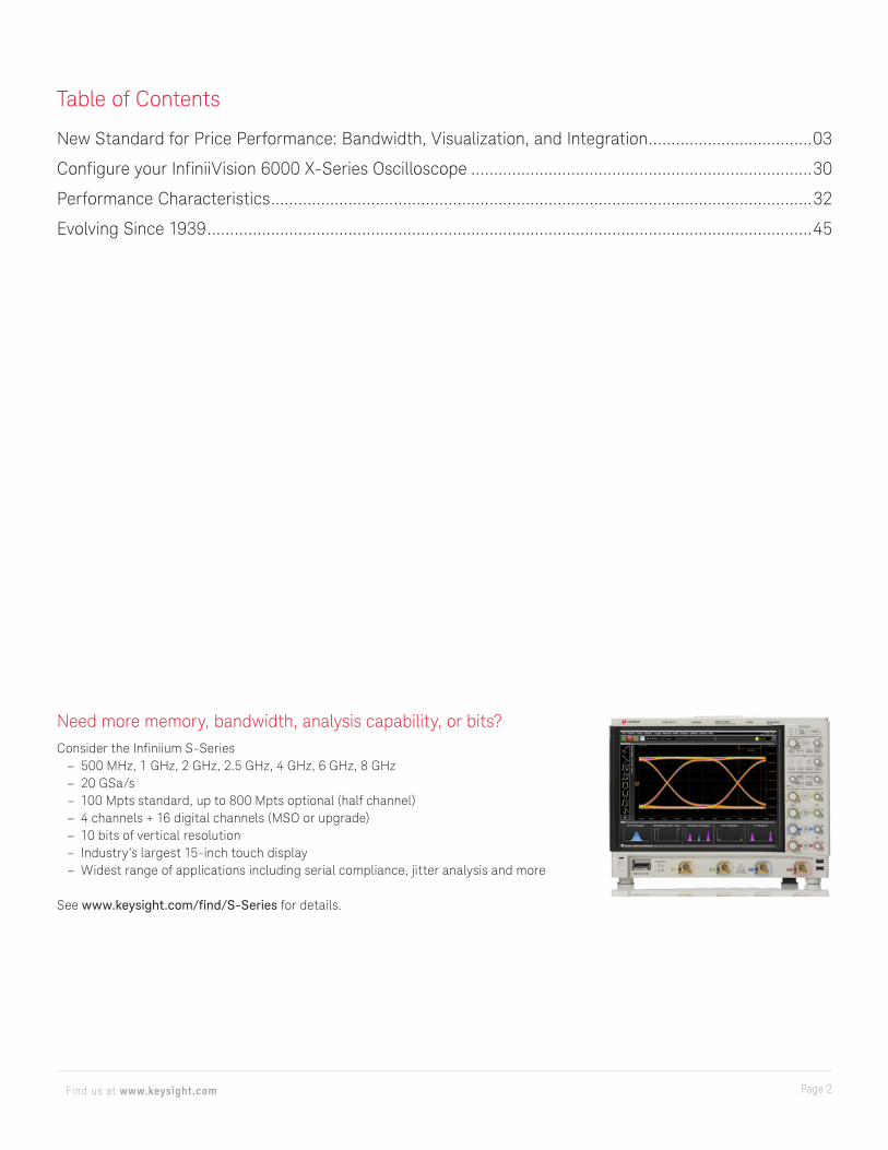
Need more memory, bandwidth, analysis capability, or bits?Consider the Infiniium S-Series
– 500 MHz, 1 GHz, 2 GHz, 2.5 GHz, 4 GHz, 6 GHz, 8 GHz – 20 GSa/s – 100 Mpts standard, up to 800 Mpts optional (half channel) – 4 channels + 16 digital channels (MSO or upgrade) – 10 bits of vertical resolution – Industry’s largest 15-inch touch display – Widest range of applications including serial compliance, jitter analysis and more
See www.keysight.com/find/S-Series for details.
Table of Contents
New Standard for Price Performance: Bandwidth, Visualization, and Integration ....................................03
Configure your InfiniiVision 6000 X-Series Oscilloscope ...........................................................................30
Performance Characteristics .......................................................................................................................32
Evolving Since 1939 .....................................................................................................................................45

Page 3Find us at www.keysight.com
In the past, if you wanted an oscilloscope with exceptional performance, you could expect to pay a premium. Not anymore. The InfiniiVision 6000 X-Series oscilloscopes combine price and performance to set a new standard in the portable oscilloscope world. Imagine a 6 GHz bandwidth oscilloscope that sees and triggers on everything, helps you visualize complex waveforms and grows with your projects.
The InfiniiVision 6000 X-Series oscilloscopes are designed for the most demanding engineers who want bandwidth, visualization power and the flexibility that comes with integrated capabilities — but with portability, a familiar embedded OS user interface, and an affordable price.
New bandwidth standard: Capture higher-frequency waveformsAn oscilloscope’s bandwidth determines the maximum frequency content it can acquire and visualize. In today’s budget-challenged environment, engineers frequently are forced to make compromises between more bandwidth and limited budget. The 6000 X-Series delivers the answer with an affordable 6-GHz bandwidth and an incredibly low noise floor of 210 µVrms at 1 mV/div to help you make the most accurate measurements.
New visualization standard: Isolate waveforms of interestThe new InfiniiVision 6000 X-Series’ 450,000 waveforms-per-second update rate coupled with the exclusive hardware-based zone touch trigger provide unprecedented visualization power to help you isolate your waveforms of interest. Add a whole new depth of “visualization” to your designs with features like the industry’s first 12-inch multi-touch capacitive touch screen with gesture support, the first embedded-OS-oscilloscope optional jitter/real-time eye analysis, and standard histogram and color grade.
New integration standard: Make your job easierThe 6000 X-Series has 7-in-1 integration, combining digital channels, serial protocol analysis, a built-in dual-channel waveform generator, frequency response analysis, built-in digital multimeter, and built-in 10-digit counter with totalizer. It also integrates multi-language voice control for the first time in an oscilloscope. It weighs only 6.8 kg, measures only 15.4 cm deep, and consumes only 200 W, making the 6000 X-Series the world’s most environmentally-friendly multi-GHz portable oscilloscope.
The InfiniiVision 6000 X-Series sets the new standard.
Key features of the 6000 X-Series oscilloscopes
New bandwidth standard: – Portable, 6-GHz, 20-GSa/s – 210-µVrms noise floor at 1 mV/div (6 GHz) – 115-µVrms noise floor at 1 mV/div (1 GHz)
New visualization standard: – > 450,000 wfms/sec update rate – Hardware zone touch trigger – 12.1-inch capacitive multi-touch screen – Histogram, color grade, jitter analysis (option), real-time eye
diagram analysis (option), and more
New integration standard: – 7 instruments in 1 (now with 10-digit counter) – Standard multi-language voice control – Bandwidth and options are upgradable
New Standard for Price Performance: Bandwidth, Visualization, and Integration
Page 4Find us at www.keysight.com
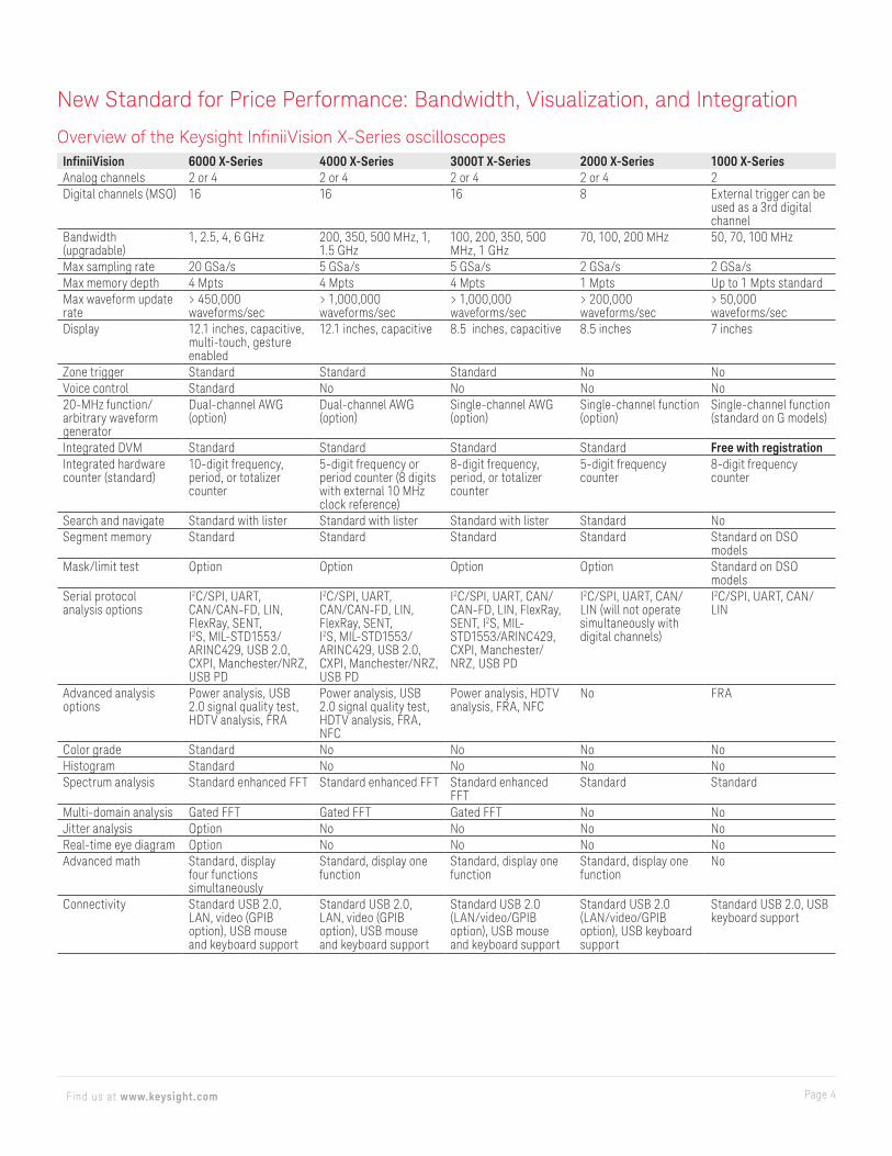
Overview of the Keysight InfiniiVision X-Series oscilloscopesInfiniiVision 6000 X-Series 4000 X-Series 3000T X-Series 2000 X-Series 1000 X-SeriesAnalog channels 2 or 4 2 or 4 2 or 4 2 or 4 2Digital channels (MSO) 16 16 16 8 External trigger can be
used as a 3rd digital channel
Bandwidth (upgradable)
1, 2.5, 4, 6 GHz 200, 350, 500 MHz, 1, 1.5 GHz
100, 200, 350, 500 MHz, 1 GHz
70, 100, 200 MHz 50, 70, 100 MHz
Max sampling rate 20 GSa/s 5 GSa/s 5 GSa/s 2 GSa/s 2 GSa/sMax memory depth 4 Mpts 4 Mpts 4 Mpts 1 Mpts Up to 1 Mpts standardMax waveform update rate
> 450,000 waveforms/sec
> 1,000,000 waveforms/sec
> 1,000,000 waveforms/sec
> 200,000 waveforms/sec
> 50,000 waveforms/sec
Display 12.1 inches, capacitive, multi-touch, gesture enabled
12.1 inches, capacitive 8.5 inches, capacitive 8.5 inches 7 inches
Zone trigger Standard Standard Standard No NoVoice control Standard No No No No20-MHz function/arbitrary waveform generator
Dual-channel AWG (option)
Dual-channel AWG (option)
Single-channel AWG (option)
Single-channel function (option)
Single-channel function (standard on G models)
Integrated DVM Standard Standard Standard Standard Free with registrationIntegrated hardware counter (standard)
10-digit frequency, period, or totalizer counter
5-digit frequency or period counter (8 digits with external 10 MHz clock reference)
8-digit frequency, period, or totalizer counter
5-digit frequency counter
8-digit frequency counter
Search and navigate Standard with lister Standard with lister Standard with lister Standard NoSegment memory Standard Standard Standard Standard Standard on DSO
modelsMask/limit test Option Option Option Option Standard on DSO
modelsSerial protocol analysis options
I2C/SPI, UART, CAN/CAN-FD, LIN, FlexRay, SENT, I2S, MIL-STD1553/ARINC429, USB 2.0, CXPI, Manchester/NRZ, USB PD
I2C/SPI, UART, CAN/CAN-FD, LIN, FlexRay, SENT, I2S, MIL-STD1553/ARINC429, USB 2.0, CXPI, Manchester/NRZ, USB PD
I2C/SPI, UART, CAN/CAN-FD, LIN, FlexRay, SENT, I2S, MIL-STD1553/ARINC429, CXPI, Manchester/NRZ, USB PD
I2C/SPI, UART, CAN/LIN (will not operate simultaneously with digital channels)
I2C/SPI, UART, CAN/LIN
Advanced analysis options
Power analysis, USB 2.0 signal quality test, HDTV analysis, FRA
Power analysis, USB 2.0 signal quality test, HDTV analysis, FRA, NFC
Power analysis, HDTV analysis, FRA, NFC
No FRA
Color grade Standard No No No NoHistogram Standard No No No NoSpectrum analysis Standard enhanced FFT Standard enhanced FFT Standard enhanced
FFTStandard Standard
Multi-domain analysis Gated FFT Gated FFT Gated FFT No NoJitter analysis Option No No No NoReal-time eye diagram Option No No No NoAdvanced math Standard, display
four functions simultaneously
Standard, display one function
Standard, display one function
Standard, display one function
No
Connectivity Standard USB 2.0, LAN, video (GPIB option), USB mouse and keyboard support
Standard USB 2.0, LAN, video (GPIB option), USB mouse and keyboard support
Standard USB 2.0 (LAN/video/GPIB option), USB mouse and keyboard support
Standard USB 2.0 (LAN/video/GPIB option), USB keyboard support
Standard USB 2.0, USB keyboard support
New Standard for Price Performance: Bandwidth, Visualization, and Integration
Page 5Find us at www.keysight.com
New Standard for Price Performance: Bandwidth, Visualization, and Integration
Bandwidth
Superior signal integrity with total-cost- of-ownership leadership 6 GHz, 20 GSa/sWhen you choose your next oscilloscope, bandwidth is the most important specification to consider, as it defines the maximum frequency content your oscilloscope can acquire. Acquiring signals with faster edge rates or faster fundamental frequencies requires higher-bandwidth scopes to make the most accurate measurements. However, the higher the bandwidth of your oscilloscope, the higher the price is likely to be.
Sample rate is the second important specification, as it determines the time span between each acquired sample point, and it ultimately becomes the limiting factor of the oscilloscope’s bandwidth. In a modern oscilloscope with Brickwall filter response, the sample rate must be at least 2.5 times higher the bandwidth. So a scope with 6-GHz bandwidth requires a sample rate of at least 15 GSa/s to avoid aliasing.
With the InfiniiVision 6000 X-Series, you can get up to 6-GHz bandwidth and a 20-GSa/s sampling rate so you can confidently measure signals with rise times faster than 150 ps or signals with higher than 2-Gbps NRZ (non-return to zero) data signal rates.
Explore Figures 1 through 4 to see the power extra bandwidth delivers to your measurements.
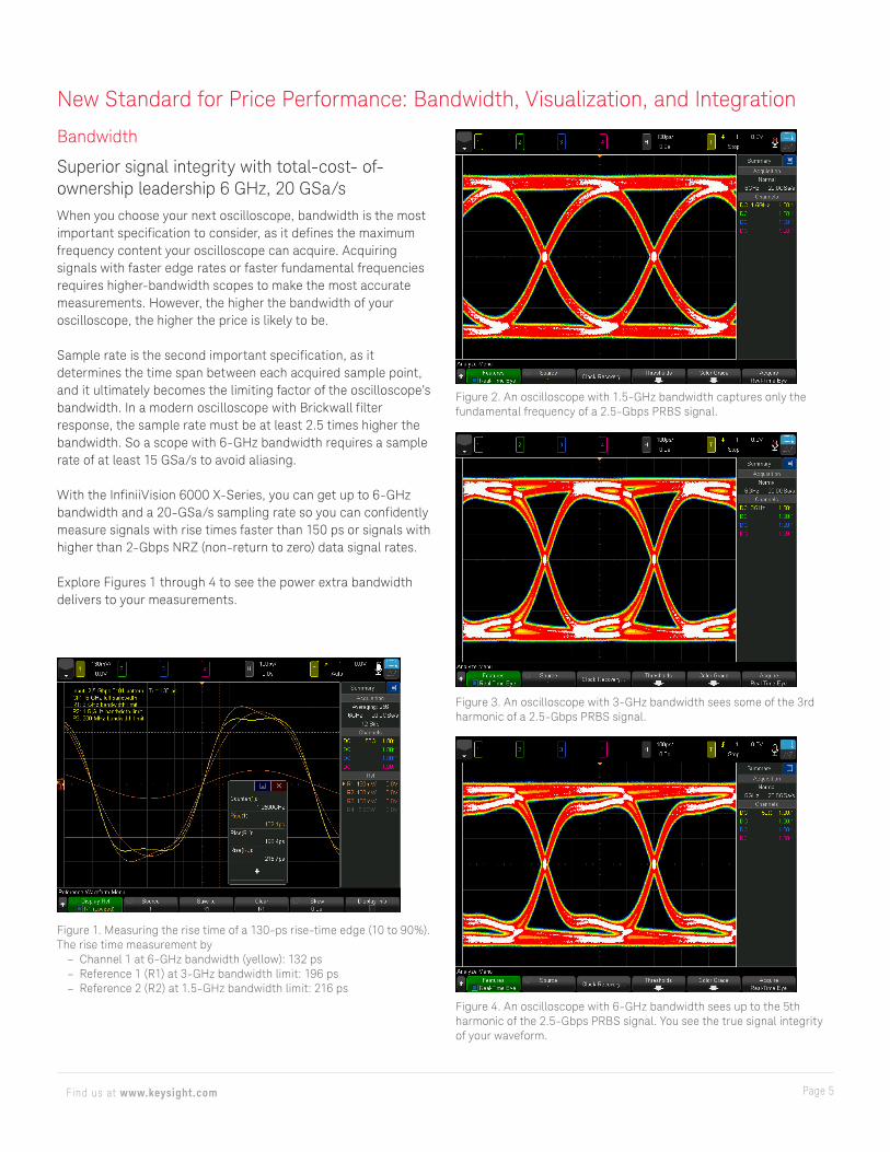
Figure 1. Measuring the rise time of a 130-ps rise-time edge (10 to 90%). The rise time measurement by
– Channel 1 at 6-GHz bandwidth (yellow): 132 ps – Reference 1 (R1) at 3-GHz bandwidth limit: 196 ps – Reference 2 (R2) at 1.5-GHz bandwidth limit: 216 ps
Figure 2. An oscilloscope with 1.5-GHz bandwidth captures only the fundamental frequency of a 2.5-Gbps PRBS signal.
Figure 3. An oscilloscope with 3-GHz bandwidth sees some of the 3rd harmonic of a 2.5-Gbps PRBS signal.
Figure 4. An oscilloscope with 6-GHz bandwidth sees up to the 5th harmonic of the 2.5-Gbps PRBS signal. You see the true signal integrity of your waveform.
Page 6Find us at www.keysight.com
New Standard for Price Performance: Bandwidth, Visualization, and Integration
Bandwidth (Continued)
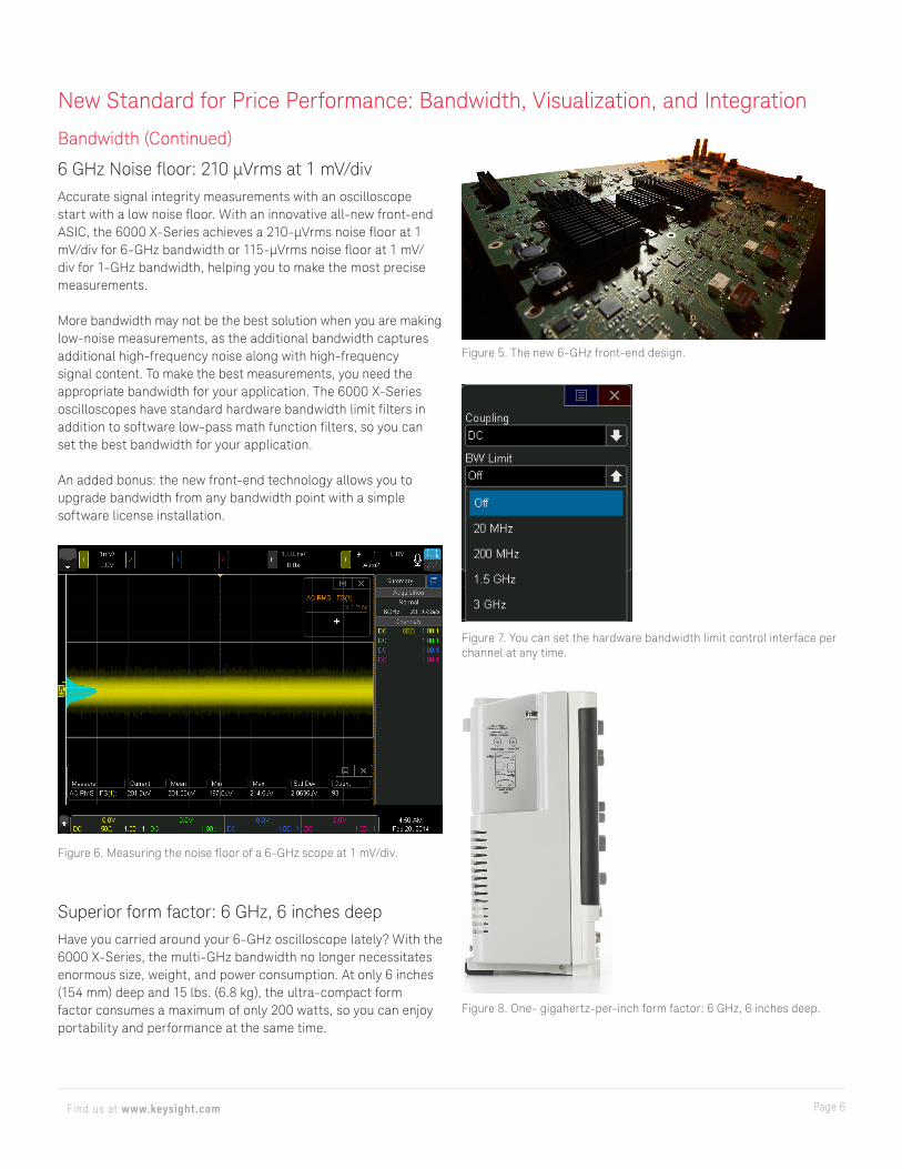
6 GHz Noise floor: 210 µVrms at 1 mV/divAccurate signal integrity measurements with an oscilloscope start with a low noise floor. With an innovative all-new front-end ASIC, the 6000 X-Series achieves a 210-μVrms noise floor at 1 mV/div for 6-GHz bandwidth or 115-μVrms noise floor at 1 mV/div for 1-GHz bandwidth, helping you to make the most precise measurements.
More bandwidth may not be the best solution when you are making low-noise measurements, as the additional bandwidth captures additional high-frequency noise along with high-frequency signal content. To make the best measurements, you need the appropriate bandwidth for your application. The 6000 X-Series oscilloscopes have standard hardware bandwidth limit filters in addition to software low-pass math function filters, so you can set the best bandwidth for your application.
An added bonus: the new front-end technology allows you to upgrade bandwidth from any bandwidth point with a simple software license installation.
Superior form factor: 6 GHz, 6 inches deepHave you carried around your 6-GHz oscilloscope lately? With the 6000 X-Series, the multi-GHz bandwidth no longer necessitates enormous size, weight, and power consumption. At only 6 inches (154 mm) deep and 15 lbs. (6.8 kg), the ultra-compact form factor consumes a maximum of only 200 watts, so you can enjoy portability and performance at the same time.
Figure 6. Measuring the noise floor of a 6-GHz scope at 1 mV/div.
Figure 5. The new 6-GHz front-end design.
Figure 7. You can set the hardware bandwidth limit control interface per channel at any time.
Figure 8. One- gigahertz-per-inch form factor: 6 GHz, 6 inches deep.
Page 7Find us at www.keysight.com
New Standard for Price Performance: Bandwidth, Visualization, and Integration
Visualization
The power of visualization: If you can’t see it, you can’t fix itTroubleshooting always starts with an acknowledgment of the problem, and a visual confirmation adds confidence in engineering troubleshooting. The feature-rich 6000 X-Series oscilloscopes include numerous visualization features offered for the first time in embedded-OS-class oscilloscopes.
Use the 6000 X-Series’ 12.1-inch multi-touch screen just like you use your tablet or smartphoneSee your waveforms clearly on the large 12.1-inch display and discover how easy it is to troubleshoot your designs with a multi-touch screen with gesture controls. Use the large, easily touchable targets on the capacitive display and enjoy the fast, responsive user interface. Pinch and zoom with your fingers to control your signals and functions. Swipe and stop waveforms and menus for easy operation.
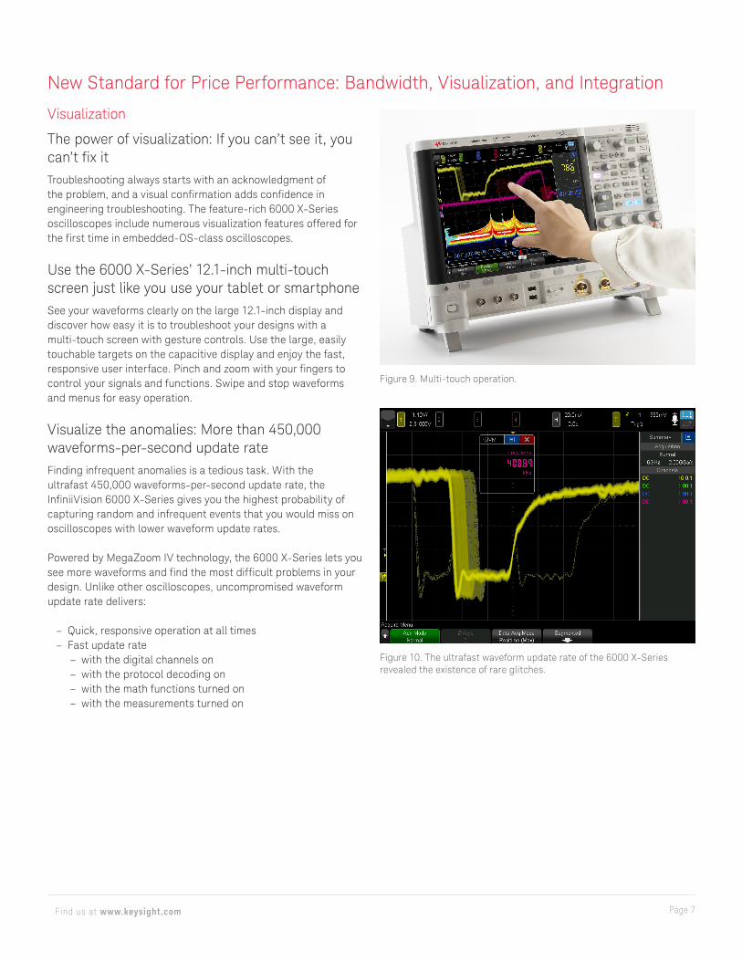
Visualize the anomalies: More than 450,000 waveforms-per-second update rateFinding infrequent anomalies is a tedious task. With the ultrafast 450,000 waveforms-per-second update rate, the InfiniiVision 6000 X-Series gives you the highest probability of capturing random and infrequent events that you would miss on oscilloscopes with lower waveform update rates.
Powered by MegaZoom IV technology, the 6000 X-Series lets you see more waveforms and find the most difficult problems in your design. Unlike other oscilloscopes, uncompromised waveform update rate delivers:
– Quick, responsive operation at all times – Fast update rate
– with the digital channels on – with the protocol decoding on – with the math functions turned on – with the measurements turned on
Figure 9. Multi-touch operation.
Figure 10. The ultrafast waveform update rate of the 6000 X-Series revealed the existence of rare glitches.
Page 8Find us at www.keysight.com
New Standard for Price Performance: Bandwidth, Visualization, and Integration
Visualization (Continued)
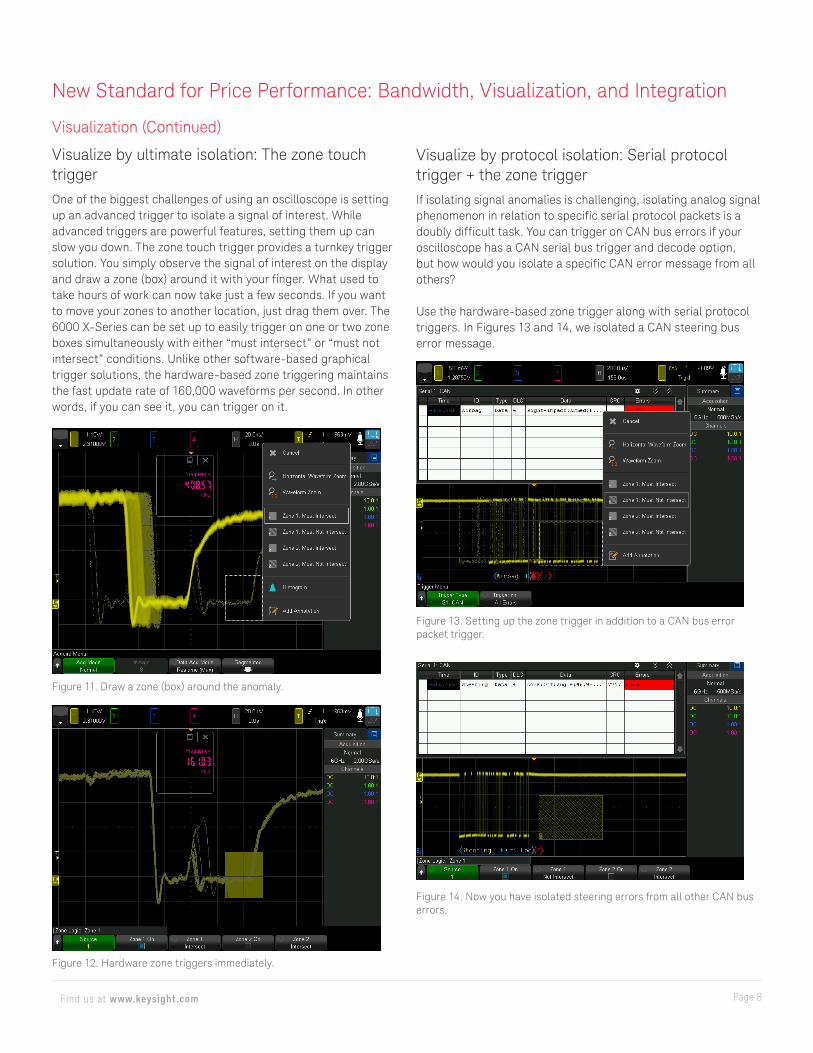
Visualize by ultimate isolation: The zone touch triggerOne of the biggest challenges of using an oscilloscope is setting up an advanced trigger to isolate a signal of interest. While advanced triggers are powerful features, setting them up can slow you down. The zone touch trigger provides a turnkey trigger solution. You simply observe the signal of interest on the display and draw a zone (box) around it with your finger. What used to take hours of work can now take just a few seconds. If you want to move your zones to another location, just drag them over. The 6000 X-Series can be set up to easily trigger on one or two zone boxes simultaneously with either “must intersect” or “must not intersect” conditions. Unlike other software-based graphical trigger solutions, the hardware-based zone triggering maintains the fast update rate of 160,000 waveforms per second. In other words, if you can see it, you can trigger on it.
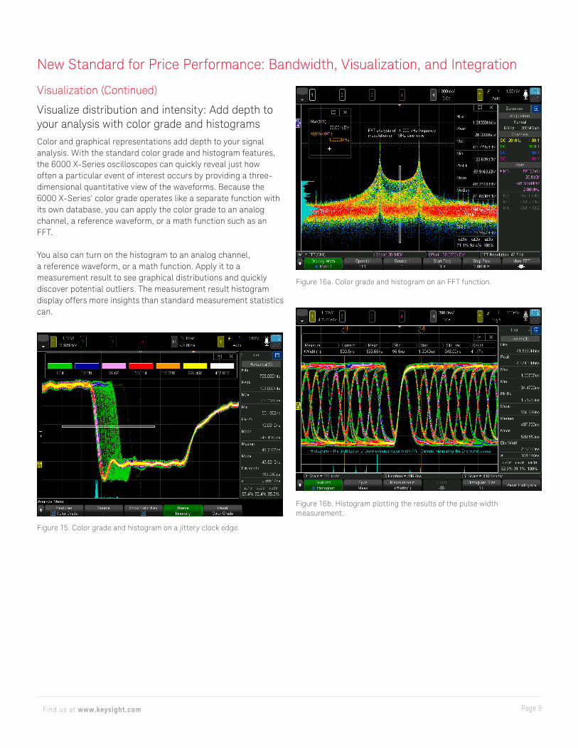
Visualize by protocol isolation: Serial protocol trigger + the zone triggerIf isolating signal anomalies is challenging, isolating analog signal phenomenon in relation to specific serial protocol packets is a doubly difficult task. You can trigger on CAN bus errors if your oscilloscope has a CAN serial bus trigger and decode option, but how would you isolate a specific CAN error message from all others?
Use the hardware-based zone trigger along with serial protocol triggers. In Figures 13 and 14, we isolated a CAN steering bus error message.
Figure 11. Draw a zone (box) around the anomaly.
Figure 12. Hardware zone triggers immediately.
Figure 13. Setting up the zone trigger in addition to a CAN bus error packet trigger.
Figure 14. Now you have isolated steering errors from all other CAN bus errors.
Page 9Find us at www.keysight.com
New Standard for Price Performance: Bandwidth, Visualization, and Integration
Visualization (Continued)
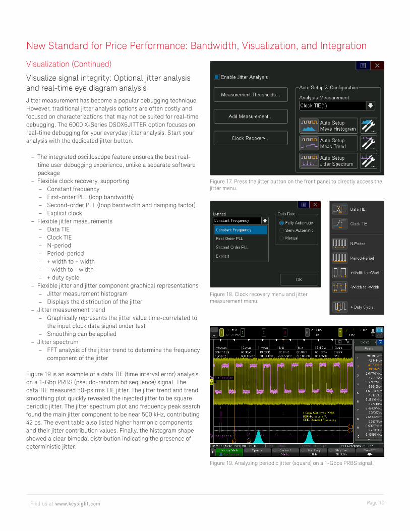
Visualize distribution and intensity: Add depth to your analysis with color grade and histogramsColor and graphical representations add depth to your signal analysis. With the standard color grade and histogram features, the 6000 X-Series oscilloscopes can quickly reveal just how often a particular event of interest occurs by providing a three-dimensional quantitative view of the waveforms. Because the 6000 X-Series’ color grade operates like a separate function with its own database, you can apply the color grade to an analog channel, a reference waveform, or a math function such as an FFT.
You also can turn on the histogram to an analog channel, a reference waveform, or a math function. Apply it to a measurement result to see graphical distributions and quickly discover potential outliers. The measurement result histogram display offers more insights than standard measurement statistics can.
Figure 15. Color grade and histogram on a jittery clock edge.
Figure 16a. Color grade and histogram on an FFT function.
Figure 16b. Histogram plotting the results of the pulse width measurement.
Page 10Find us at www.keysight.com
New Standard for Price Performance: Bandwidth, Visualization, and Integration
Visualization (Continued)
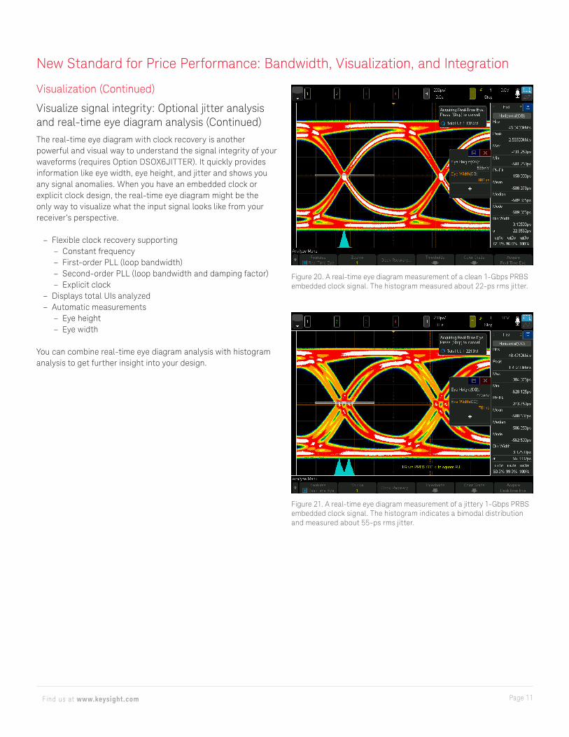
Visualize signal integrity: Optional jitter analysis and real-time eye diagram analysisJitter measurement has become a popular debugging technique. However, traditional jitter analysis options are often costly and focused on characterizations that may not be suited for real-time debugging. The 6000 X-Series DSOX6JITTER option focuses on real-time debugging for your everyday jitter analysis. Start your analysis with the dedicated jitter button.
– The integrated oscilloscope feature ensures the best real-time user debugging experience, unlike a separate softwarepackage
– Flexible clock recovery, supporting – Constant frequency – First-order PLL (loop bandwidth) – Second-order PLL (loop bandwidth and damping factor) – Explicit clock
– Flexible jitter measurements – Data TIE – Clock TIE – N-period – Period-period – + width to + width – - width to - width – + duty cycle
– Flexible jitter and jitter component graphical representations – Jitter measurement histogram – Displays the distribution of the jitter
– Jitter measurement trend – Graphically represents the jitter value time-correlated to
the input clock data signal under test – Smoothing can be applied
– Jitter spectrum – FFT analysis of the jitter trend to determine the frequency
component of the jitter
Figure 19 is an example of a data TIE (time interval error) analysis on a 1-Gbp PRBS (pseudo-random bit sequence) signal. The data TIE measured 50-ps rms TIE jitter. The jitter trend and trend smoothing plot quickly revealed the injected jitter to be square periodic jitter. The jitter spectrum plot and frequency peak search found the main jitter component to be near 500 kHz, contributing 42 ps. The event table also listed higher harmonic components and their jitter contribution values. Finally, the histogram shape showed a clear bimodal distribution indicating the presence of deterministic jitter.
Figure 17. Press the jitter button on the front panel to directly access the jitter menu.
Figure 18. Clock recovery menu and jitter measurement menu.
Figure 19. Analyzing periodic jitter (square) on a 1-Gbps PRBS signal.
Page 11Find us at www.keysight.com
New Standard for Price Performance: Bandwidth, Visualization, and Integration
Visualization (Continued)
Visualize signal integrity: Optional jitter analysis and real-time eye diagram analysis (Continued)The real-time eye diagram with clock recovery is another powerful and visual way to understand the signal integrity of your waveforms (requires Option DSOX6JITTER). It quickly provides information like eye width, eye height, and jitter and shows you any signal anomalies. When you have an embedded clock or explicit clock design, the real-time eye diagram might be the only way to visualize what the input signal looks like from your receiver’s perspective.
– Flexible clock recovery supporting – Constant frequency – First-order PLL (loop bandwidth) – Second-order PLL (loop bandwidth and damping factor) – Explicit clock
– Displays total UIs analyzed – Automatic measurements
– Eye height – Eye width
You can combine real-time eye diagram analysis with histogram analysis to get further insight into your design.
Figure 20. A real-time eye diagram measurement of a clean 1-Gbps PRBS embedded clock signal. The histogram measured about 22-ps rms jitter.
Figure 21. A real-time eye diagram measurement of a jittery 1-Gbps PRBS embedded clock signal. The histogram indicates a bimodal distribution and measured about 55-ps rms jitter.

Page 12Find us at www.keysight.com
Figure 22. Segmented memory graphical representation.
New Standard for Price Performance: Bandwidth, Visualization, and Integration
Visualization (Continued)
Visualize burst events: Segmented memory — the smart and efficient wayAcquisition memory size is an essential oscilloscope specification because it determines the amount of data you can capture in a single acquisition. In general, longer memory is better. However, no memory is always long enough to capture all the signals you need, especially when capturing infrequent anomalies or rare critical serial bus error packets. Also, user interface responsiveness typically slows down dramatically with the long memory operations. Segmented memory acquisition lets you selectively capture and store important signal activity without capturing unimportant signal idle time, with a time stamp of each segment relative to the first trigger event.
For example, we have captured 1000 rare glitches over a time span of 128 seconds with 5-GSa/s resolution in Figures 22 through 24. Automatically scrolling through all segments, we found segment 22 at 1.7 seconds after the trigger, segment 61 at 5.3 seconds after trigger, and segment 153 at 14 seconds after the trigger contained some of the worst glitches. The new event lister of time stamps provides quick insight into the time gap between glitches. With traditional unsegmented memory, 640 Gpts of memory is required to do similar analysis.
With the 6000 X-Series, you can combine the segmented memory with the color grade and histogram features as well.
Figure 23. Segmented memory and color grade.
Figure 24. Segmented memory time-tag lister.
Figure 25. Segmented memory + serial bus decode + zone trigger.
Visualize and isolate burst events: Zone touch trigger and segmented memoryThe combination of the hardware-based zone touch trigger with the 6000 X-Series’ segmented memory simplifies your debugging tasks. In Figure 25, the 6000 X-Series’ serial bus trigger, zone touch trigger, and segmented memory isolated and captured 200 CAN steering and airbag errors over a 30-second time span at 6.1-MSa/s sampling rate in the segmented memory. This time duration equates to 192 Mpts of traditional memory.
Captured error packets are displayed chronologically at the side of the screen in the event lister so you can easily look up time stamps. You can independently save the time stamp information as well.

Page 13Find us at www.keysight.com
New Standard for Price Performance: Bandwidth, Visualization, and Integration
IntegrationTake advantage of a new oscilloscope application bundle that will enable ALL software applications (including serial decode and WaveGen) for one low price (Option DSOX6APPBNDL).
More than just an oscilloscope, it’s 7 instruments in 1Keysight Technologies, Inc. pioneered multiple-instrument integration with the release of the mixed signal oscilloscope (MSO) in 1996. The InfiniiVision 2000/3000/4000X-Series took the concept to the next level by integrating five instruments in one in 2011. The InfiniiVision 6000 X-Series now integrates seven instruments in one to establish a new integration standard.
– Oscilloscope – 16 digital channels (mixed signal) – Serial protocol analyzer – Dual-channel 20-MHz function/arbitrary waveform
generator – Frequency response analysis – 3-digit voltmeter – 10-digit counter with totalizer
All features and bandwidth are upgradable.
Integrate a digital bus: Optional mixed signal oscilloscope (MSO models)With an additional optional 16 integrated digital channels (Option DSOX6MSO) probed by a newly designed digital channel cable, you now have up to 20 channels of time-correlated triggering, acquisition, and viewing on the same instrument. This capability is especially important in today’s embedded designs with sophisticated digital control circuitry.
Integrate a generator: Optional dual-channel 20-MHz function/arbitrary waveform generatorAn optional integrated dual-channel 20-MHz function/arbitrary waveform generator (Option DSOX6WAVEGEN2) is available for the 6000 X-Series. The integrated generator can provide stimulus outputs of sine, square, ramp, pulse, DC, noise, sine, cardinal (sinc), exponential rise, exponential fall, cardiac, Gaussian pulse and arbitrary waveforms to your device under test. Signal modulation capability is also available.
With the arbitrary waveform functionality, you can store waveforms from analog channels or reference memories to the arbitrary memories with a single touch and output from WaveGen.
Easily create and edit the waveform using the built-in waveform editor or export the data in a .csv file and edit it with your favorite editing tool.
Figure 26. Analog and digital signals displayed together with the logic timing chart function.
Figure 27. MSO with a new digital channel cable.
Figure 28. Arbitrary waveform generation signal editing screen.
Page 14Find us at www.keysight.com
New Standard for Price Performance: Bandwidth, Visualization, and Integration
Integration (Continued)
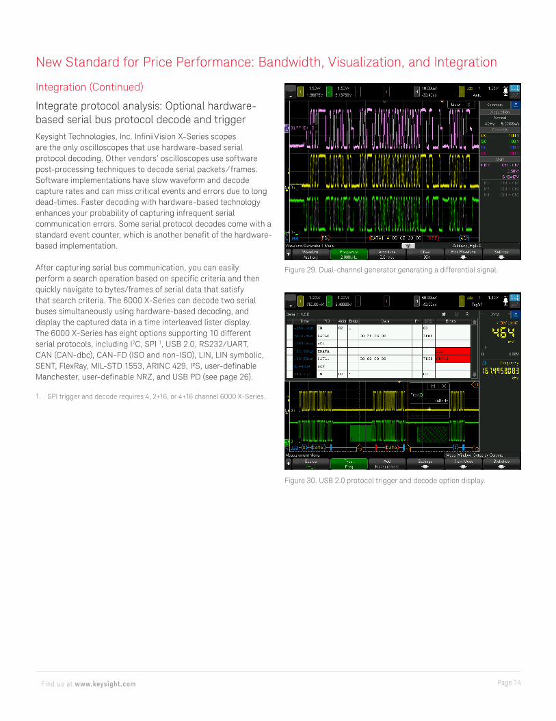
Integrate protocol analysis: Optional hardware- based serial bus protocol decode and triggerKeysight Technologies, Inc. InfiniiVision X-Series scopes are the only oscilloscopes that use hardware-based serial protocol decoding. Other vendors’ oscilloscopes use software post-processing techniques to decode serial packets ⁄ frames. Software implementations have slow waveform and decode capture rates and can miss critical events and errors due to long dead-times. Faster decoding with hardware-based technology enhances your probability of capturing infrequent serial communication errors. Some serial protocol decodes come with a standard event counter, which is another benefit of the hardware-based implementation.
After capturing serial bus communication, you can easily perform a search operation based on specific criteria and then quickly navigate to bytes/frames of serial data that satisfy that search criteria. The 6000 X-Series can decode two serial buses simultaneously using hardware-based decoding, and display the captured data in a time interleaved lister display. The 6000 X-Series has eight options supporting 10 different serial protocols, including I2C, SPI 1, USB 2.0, RS232/UART, CAN (CAN-dbc), CAN-FD (ISO and non-ISO), LIN, LIN symbolic, SENT, FlexRay, MIL-STD 1553, ARINC 429, I²S, user-definable Manchester, user-definable NRZ, and USB PD (see page 26).
1. SPI trigger and decode requires 4, 2+16, or 4+16 channel 6000 X-Series.
Figure 29. Dual-channel generator generating a differential signal.
Figure 30. USB 2.0 protocol trigger and decode option display.
Page 15Find us at www.keysight.com
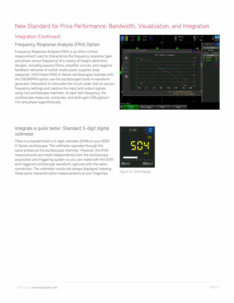
Figure 31. DVM display.
Integrate a quick tester: Standard 3-digit digital voltmeterThere is a standard built-in 3-digit voltmeter (DVM) on your 6000 X-Series oscilloscope. The voltmeter operates through thesame probes as the oscilloscope channels. However, the DVMmeasurements are made independently from the oscilloscopeacquisition and triggering system so you can make both the DVMand triggered oscilloscope waveform captures with the sameconnection. The voltmeter results are always displayed, keepingthese quick characterization measurements at your fingertips.
Integration (Continued)
Frequency Response Analysis (FRA) OptionFrequency Response Analysis (FRA) is an often-critical measurement used to characterize the frequency response (gain and phase versus frequency) of a variety of today’s electronic designs, including passive filters, amplifier circuits, and negative feedback networks of switch mode power supplies (loop response). InfiniiVision 6000 X-Series oscilloscopes licensed with the DSOX6FRA option use the oscilloscope’s built-in waveform generator (WaveGen) to stimulate the circuit under test at various frequency settings and capture the input and output signals using two oscilloscope channels. At each test frequency, the oscilloscope measures, computes, and plots gain (20LogVout/Vin) and phase logarithmically.
New Standard for Price Performance: Bandwidth, Visualization, and Integration
Page 16Find us at www.keysight.com
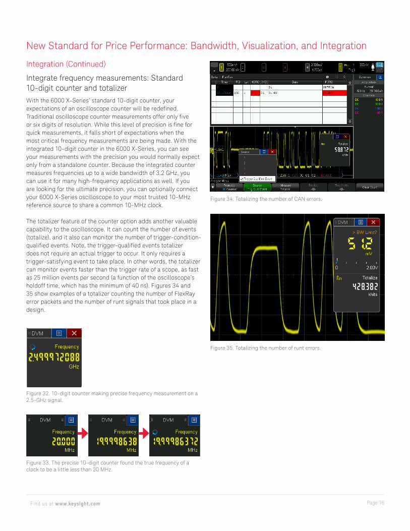
Figure 32. 10-digit counter making precise frequency measurement on a 2.5-GHz signal.
Figure 33. The precise 10-digit counter found the true frequency of a clock to be a little less than 20 MHz.
New Standard for Price Performance: Bandwidth, Visualization, and Integration
Integration (Continued)
Integrate frequency measurements: Standard 10-digit counter and totalizerWith the 6000 X-Series’ standard 10-digit counter, your expectations of an oscilloscope counter will be redefined. Traditional oscilloscope counter measurements offer only five or six digits of resolution. While this level of precision is fine for quick measurements, it falls short of expectations when the most critical frequency measurements are being made. With the integrated 10-digit counter in the 6000 X-Series, you can see your measurements with the precision you would normally expect only from a standalone counter. Because the integrated counter measures frequencies up to a wide bandwidth of 3.2 GHz, you can use it for many high-frequency applications as well. If you are looking for the ultimate precision, you can optionally connect your 6000 X-Series oscilloscope to your most trusted 10-MHz reference source to share a common 10-MHz clock.
The totalizer feature of the counter option adds another valuable capability to the oscilloscope. It can count the number of events (totalize), and it also can monitor the number of trigger-condition-qualified events. Note, the trigger-qualified events totalizer does not require an actual trigger to occur. It only requires a trigger-satisfying event to take place. In other words, the totalizer can monitor events faster than the trigger rate of a scope, as fast as 25 million events per second (a function of the oscilloscope’s holdoff time, which has the minimum of 40 ns). Figures 34 and 35 show examples of a totalizer counting the number of FlexRay error packets and the number of runt signals that took place in a design.
Figure 34. Totalizing the number of CAN errors.
Figure 35. Totalizing the number of runt errors.
Page 17Find us at www.keysight.com
New Standard for Price Performance: Bandwidth, Visualization, and Integration
Integration (Continued)
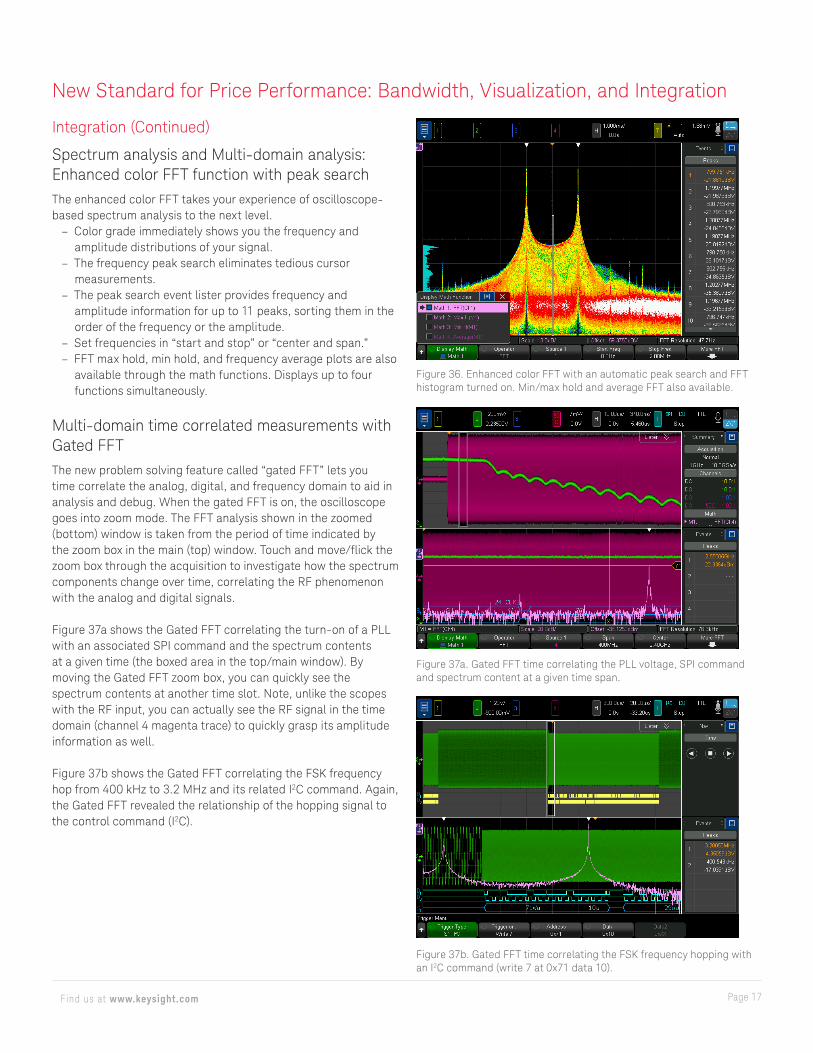
Spectrum analysis and Multi-domain analysis: Enhanced color FFT function with peak searchThe enhanced color FFT takes your experience of oscilloscope-based spectrum analysis to the next level.
– Color grade immediately shows you the frequency andamplitude distributions of your signal.
– The frequency peak search eliminates tedious cursormeasurements.
– The peak search event lister provides frequency andamplitude information for up to 11 peaks, sorting them in theorder of the frequency or the amplitude.
– Set frequencies in “start and stop” or “center and span.” – FFT max hold, min hold, and frequency average plots are also
available through the math functions. Displays up to fourfunctions simultaneously.
Multi-domain time correlated measurements with Gated FFTThe new problem solving feature called “gated FFT” lets you time correlate the analog, digital, and frequency domain to aid in analysis and debug. When the gated FFT is on, the oscilloscope goes into zoom mode. The FFT analysis shown in the zoomed (bottom) window is taken from the period of time indicated by the zoom box in the main (top) window. Touch and move/flick the zoom box through the acquisition to investigate how the spectrum components change over time, correlating the RF phenomenon with the analog and digital signals.
Figure 37a shows the Gated FFT correlating the turn-on of a PLL with an associated SPI command and the spectrum contents at a given time (the boxed area in the top/main window). By moving the Gated FFT zoom box, you can quickly see the spectrum contents at another time slot. Note, unlike the scopes with the RF input, you can actually see the RF signal in the time domain (channel 4 magenta trace) to quickly grasp its amplitude information as well.
Figure 37b shows the Gated FFT correlating the FSK frequency hop from 400 kHz to 3.2 MHz and its related I2C command. Again, the Gated FFT revealed the relationship of the hopping signal to the control command (I2C).
Figure 36. Enhanced color FFT with an automatic peak search and FFT histogram turned on. Min/max hold and average FFT also available.
Figure 37a. Gated FFT time correlating the PLL voltage, SPI command and spectrum content at a given time span.
Figure 37b. Gated FFT time correlating the FSK frequency hopping with an I2C command (write 7 at 0x71 data 10).
Page 18Find us at www.keysight.com
New Standard for Price Performance: Bandwidth, Visualization, and Integration
Integration (Continued)
Talk to me: Multi-language voice control powered by NuanceToday’s devices operate with voice controls. Your smartphone and car navigation system respond to your voice commands. Why not your oscilloscopes? The 6000 X-Series oscilloscopes’ new voice control capability not only listens to you, but it understands you in your native language. Experience hands-free oscilloscope operation by running familiar commands like “run,” “stop,” “single,” and “auto scale.” It supports 20 commands in 14 different languages and is powered by the Nuance Communications, Inc. voice recognition engine.
You can operate the 6000 X-Series in the language most familiar to you. The graphical user interface, built-in help system, front panel overlays, and user’s manuals are available in 11 languages. During operation, access the built-in help system just by pressing and holding any button or touching and holding any related icons.
Using the built-in speaker, the 6000 X-Series beeps to alert you to various events like a single trigger, mask test failure, calibration setup, and more.
Figure 38. Language list.
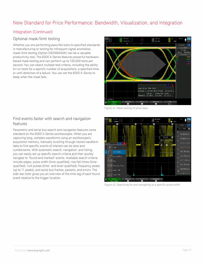
Figure 39. Voice control microphone and speaker.
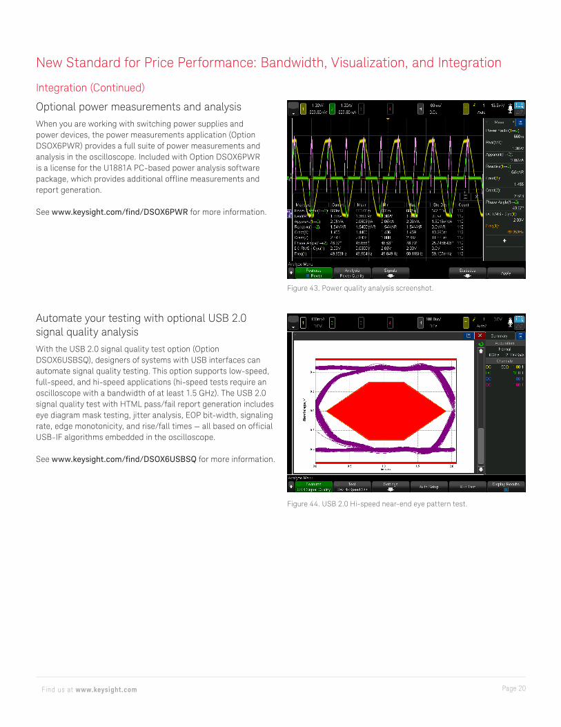
Figure 40. Limit testing of infrequent glitch.
Page 19Find us at www.keysight.com
Integration (Continued)
Optional mask/limit testingWhether you are performing pass/fail tests to specified standards in manufacturing or testing for infrequent signal anomalies, mask/limit testing (Option DSOX6MASK) can be a valuable productivity tool. The 6000 X-Series features powerful hardware-based mask testing and can perform up to 130,000 tests per second. You can select multiple test criteria, including the ability to run tests for a specific number of acquisitions, a specified time, or until detection of a failure. You can set the 6000 X-Series to beep when the mask fails.
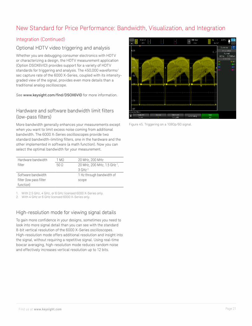
Figure 41. Mask testing of serial data.
New Standard for Price Performance: Bandwidth, Visualization, and Integration
Figure 42. Searching for and navigating to a specific pulse width.
Find events faster with search and navigation featuresParametric and serial bus search and navigation features come standard on the 6000 X-Series oscilloscopes. When you are capturing long, complex waveforms using an oscilloscope’s acquisition memory, manually scrolling through stored waveform data to find specific events of interest can be slow and cumbersome. With automatic search, navigation, and listing, you can easily set up specific search criteria and then quickly navigate to “found and marked” events. Available search criteria include edges, pulse width (time-qualified), rise/fall times (time-qualified), runt pulses (time- and level-qualified), frequency peaks (up to 11 peaks), and serial bus frames, packets, and errors. The side-bar lister gives you an overview of the time tag of each found event relative to the trigger location.
Page 20Find us at www.keysight.com
New Standard for Price Performance: Bandwidth, Visualization, and Integration
Integration (Continued)
Optional power measurements and analysisWhen you are working with switching power supplies and power devices, the power measurements application (Option DSOX6PWR) provides a full suite of power measurements and analysis in the oscilloscope. Included with Option DSOX6PWR is a license for the U1881A PC-based power analysis software package, which provides additional offline measurements and report generation.
See www.keysight.com/find/DSOX6PWR for more information.
Automate your testing with optional USB 2.0 signal quality analysisWith the USB 2.0 signal quality test option (Option DSOX6USBSQ), designers of systems with USB interfaces can automate signal quality testing. This option supports low-speed, full-speed, and hi-speed applications (hi-speed tests require an oscilloscope with a bandwidth of at least 1.5 GHz). The USB 2.0 signal quality test with HTML pass/fail report generation includes eye diagram mask testing, jitter analysis, EOP bit-width, signaling rate, edge monotonicity, and rise/fall times — all based on official USB-IF algorithms embedded in the oscilloscope.
See www.keysight.com/find/DSOX6USBSQ for more information.
Figure 43. Power quality analysis screenshot.
Figure 44. USB 2.0 Hi-speed near-end eye pattern test.
Page 21Find us at www.keysight.com
New Standard for Price Performance: Bandwidth, Visualization, and Integration
Integration (Continued)
Optional HDTV video triggering and analysisWhether you are debugging consumer electronics with HDTV or characterizing a design, the HDTV measurement application (Option DSOX6VID) provides support for a variety of HDTV standards for triggering and analysis. The 450,000 waveforms/sec capture rate of the 6000 X-Series, coupled with its intensity-graded view of the signal, provides even more details than a traditional analog oscilloscope.
See www.keysight.com/find/DSOX6VID for more information.
Hardware and software bandwidth limit filters (low-pass filters)More bandwidth generally enhances your measurements except when you want to limit excess noise coming from additional bandwidth. The 6000 X-Series oscilloscopes provide two standard bandwidth-limiting filters, one in the hardware and the other implemented in software (a math function). Now you can select the optimal bandwidth for your measurement.
Hardware bandwidth filter
1 MΩ 20 MHz, 200 MHz50 Ω 20 MHz, 200 MHz, 1.5 GHz 1,
3 GHz 2
Software bandwidth filter (low pass filter function)
1 Hz through bandwidth of scope
1. With 2.5 GHz, 4 GHz, or 6 GHz licensed 6000 X-Series only.2. With 4 GHz or 6 GHz licensed 6000 X-Series only.
High-resolution mode for viewing signal detailsTo gain more confidence in your designs, sometimes you need to look into more signal detail than you can see with the standard 8-bit vertical resolution of the 6000 X-Series oscilloscopes.High-resolution mode offers additional resolution and insight intothe signal, without requiring a repetitive signal. Using real-timeboxcar averaging, high-resolution mode reduces random noiseand effectively increases vertical resolution up to 12 bits.
Figure 45. Triggering on a 1080p/60 signal.
Page 22Find us at www.keysight.com
New Standard for Price Performance: Bandwidth, Visualization, and Integration
Integration (Continued)
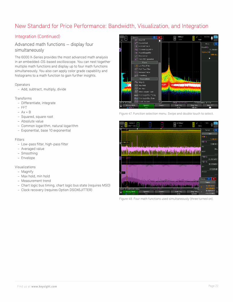
Advanced math functions — display four simultaneously The 6000 X-Series provides the most advanced math analysis in an embedded-OS-based oscilloscope. You can nest together multiple math functions and display up to four math functions simultaneously. You also can apply color grade capability and histograms to a math function to gain further insights.
Operators – Add, subtract, multiply, divide
Transforms – Differentiate, integrate – FFT – Ax + B – Squared, square root – Absolute value – Common logarithm, natural logarithm – Exponential, base 10 exponential
Filters – Low-pass filter, high-pass filter – Averaged value – Smoothing – Envelope
Visualizations – Magnify – Max hold, min hold – Measurement trend – Chart logic bus timing, chart logic bus state (requires MSO) – Clock recovery (requires Option DSOX6JITTER)
Figure 47. Function selection menu. Swipe and double touch to select.
Figure 48. Four math functions used simultaneously (three turned on).
Page 23Find us at www.keysight.com
New Standard for Price Performance: Bandwidth, Visualization, and Integration
Integration (Continued)
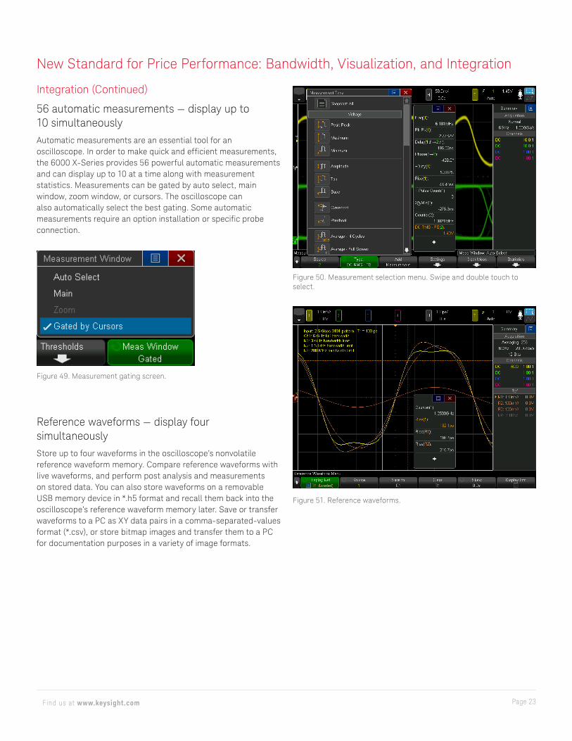
56 automatic measurements — display up to 10 simultaneouslyAutomatic measurements are an essential tool for an oscilloscope. In order to make quick and efficient measurements, the 6000 X-Series provides 56 powerful automatic measurements and can display up to 10 at a time along with measurement statistics. Measurements can be gated by auto select, main window, zoom window, or cursors. The oscilloscope can also automatically select the best gating. Some automatic measurements require an option installation or specific probe connection.
Figure 50. Measurement selection menu. Swipe and double touch to select.
Figure 51. Reference waveforms.
Figure 49. Measurement gating screen.
Reference waveforms — display four simultaneouslyStore up to four waveforms in the oscilloscope’s nonvolatile reference waveform memory. Compare reference waveforms with live waveforms, and perform post analysis and measurements on stored data. You can also store waveforms on a removable USB memory device in *.h5 format and recall them back into the oscilloscope’s reference waveform memory later. Save or transfer waveforms to a PC as XY data pairs in a comma-separated-values format (*.csv), or store bitmap images and transfer them to a PC for documentation purposes in a variety of image formats.
Page 24Find us at www.keysight.com
Integration (Continued)
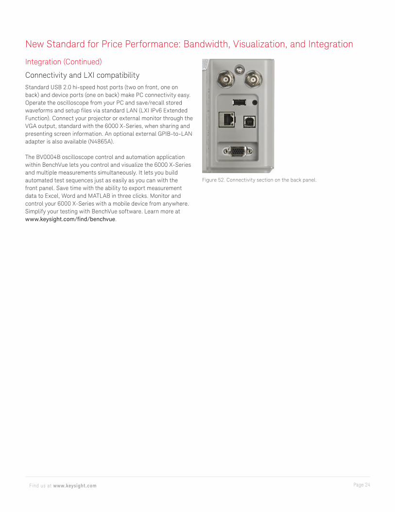
Connectivity and LXI compatibilityStandard USB 2.0 hi-speed host ports (two on front, one on back) and device ports (one on back) make PC connectivity easy. Operate the oscilloscope from your PC and save/recall stored waveforms and setup files via standard LAN (LXI IPv6 Extended Function). Connect your projector or external monitor through the VGA output, standard with the 6000 X-Series, when sharing and presenting screen information. An optional external GPIB-to-LAN adapter is also available (N4865A).
The BV0004B oscilloscope control and automation application within BenchVue lets you control and visualize the 6000 X-Series and multiple measurements simultaneously. It lets you build automated test sequences just as easily as you can with the front panel. Save time with the ability to export measurement data to Excel, Word and MATLAB in three clicks. Monitor and control your 6000 X-Series with a mobile device from anywhere. Simplify your testing with BenchVue software. Learn more at www.keysight.com/find/benchvue.
New Standard for Price Performance: Bandwidth, Visualization, and Integration
Figure 52. Connectivity section on the back panel.
Page 25Find us at www.keysight.com
Integration (Continued)
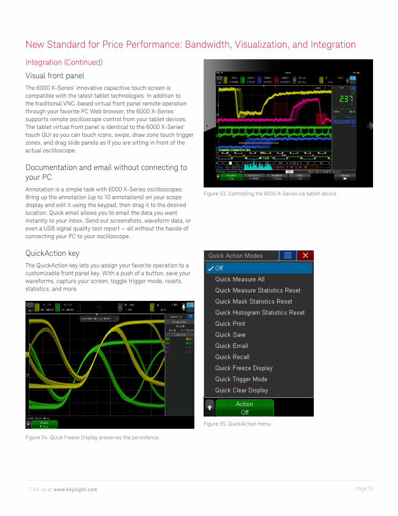
Visual front panelThe 6000 X-Series’ innovative capacitive touch screen is compatible with the latest tablet technologies. In addition to the traditional VNC-based virtual front panel remote operation through your favorite PC Web browser, the 6000 X-Series supports remote oscilloscope control from your tablet devices. The tablet virtual front panel is identical to the 6000 X-Series’ touch GUI so you can touch icons, swipe, draw zone touch trigger zones, and drag slide panels as if you are sitting in front of the actual oscilloscope.
Documentation and email without connecting to your PCAnnotation is a simple task with 6000 X-Series oscilloscopes. Bring up the annotation (up to 10 annotations) on your scope display and edit it using the keypad, then drag it to the desired location. Quick email allows you to email the data you want instantly to your inbox. Send out screenshots, waveform data, or even a USB signal quality test report — all without the hassle of connecting your PC to your oscilloscope.
QuickAction keyThe QuickAction key lets you assign your favorite operation to a customizable front panel key. With a push of a button, save your waveforms, capture your screen, toggle trigger mode, resets, statistics, and more.
Figure 53. Controlling the 6000 X-Series via tablet device.
New Standard for Price Performance: Bandwidth, Visualization, and Integration
Figure 54. Quick Freeze Display preserves the persistence.
Figure 55. QuickAction menu.
Page 26Find us at www.keysight.com
New Standard for Price Performance: Bandwidth, Visualization, and Integration
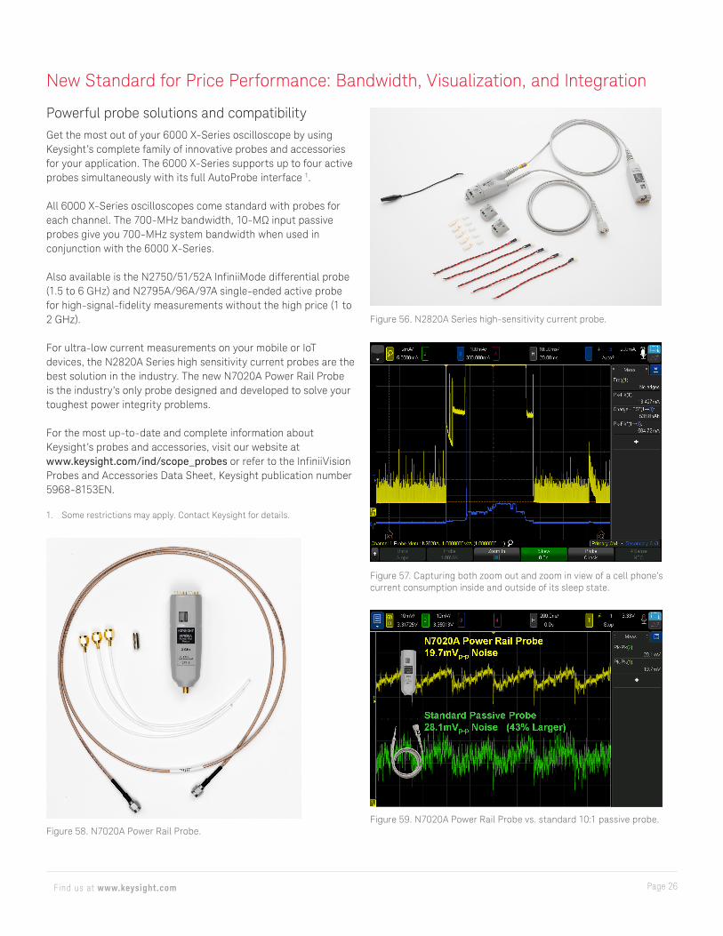
Figure 56. N2820A Series high-sensitivity current probe.
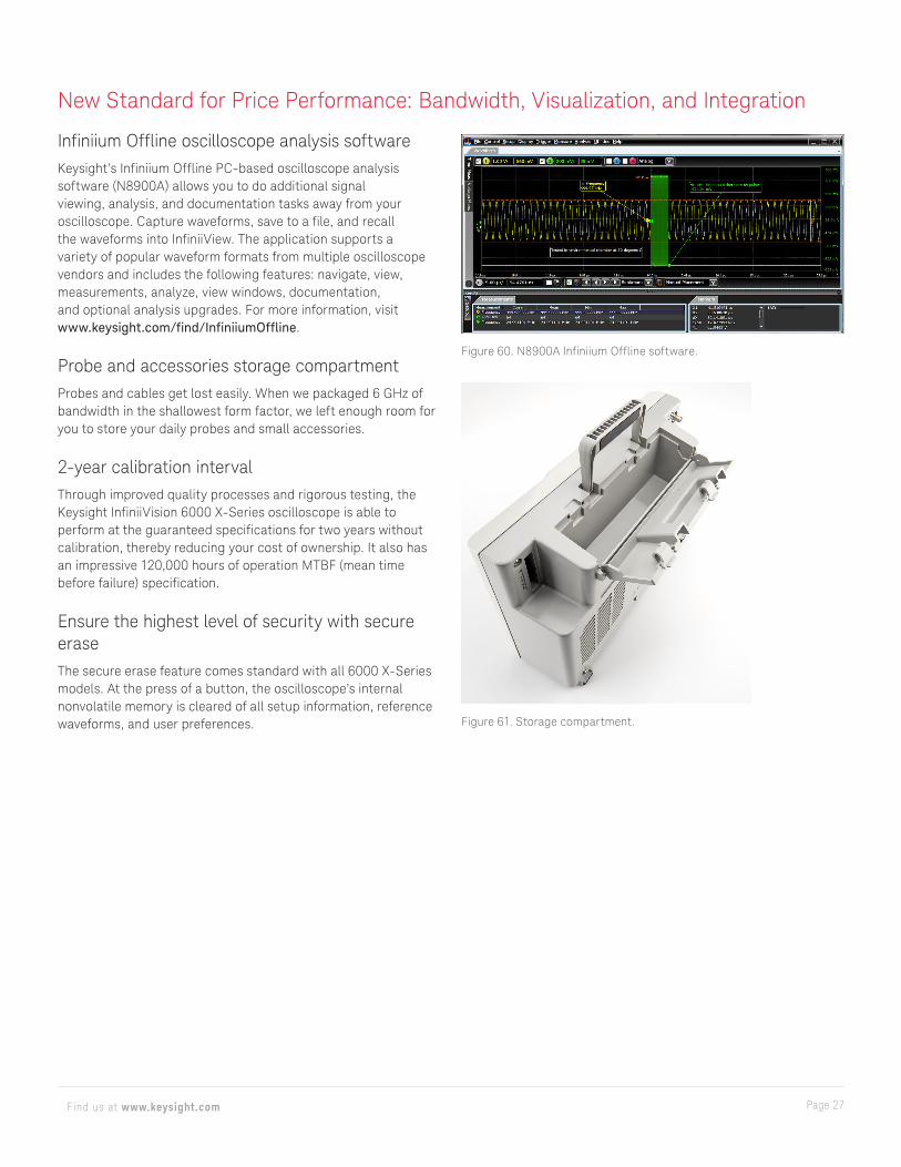
Figure 57. Capturing both zoom out and zoom in view of a cell phone’s current consumption inside and outside of its sleep state.
Powerful probe solutions and compatibilityGet the most out of your 6000 X-Series oscilloscope by using Keysight’s complete family of innovative probes and accessories for your application. The 6000 X-Series supports up to four active probes simultaneously with its full AutoProbe interface 1.
All 6000 X-Series oscilloscopes come standard with probes for each channel. The 700-MHz bandwidth, 10-MΩ input passive probes give you 700-MHz system bandwidth when used in conjunction with the 6000 X-Series.
Also available is the N2750/51/52A InfiniiMode differential probe (1.5 to 6 GHz) and N2795A/96A/97A single-ended active probe for high-signal-fidelity measurements without the high price (1 to 2 GHz).
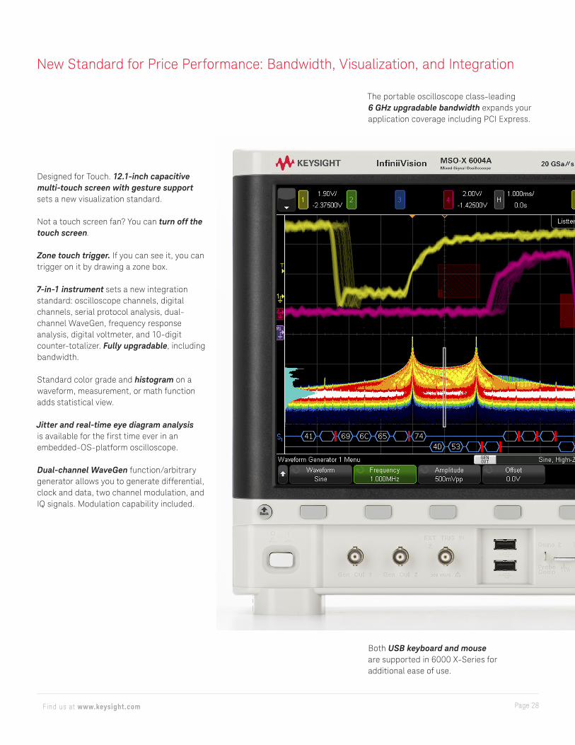
For ultra-low current measurements on your mobile or IoT devices, the N2820A Series high sensitivity current probes are the best solution in the industry. The new N7020A Power Rail Probe is the industry’s only probe designed and developed to solve your toughest power integrity problems.
For the most up-to-date and complete information about Keysight’s probes and accessories, visit our website at www.keysight.com/ind/scope_probes or refer to the InfiniiVision Probes and Accessories Data Sheet, Keysight publication number 5968-8153EN.
1. Some restrictions may apply. Contact Keysight for details.
Figure 58. N7020A Power Rail Probe.Figure 59. N7020A Power Rail Probe vs. standard 10:1 passive probe.
Page 27Find us at www.keysight.com
New Standard for Price Performance: Bandwidth, Visualization, and Integration
Infiniium Offline oscilloscope analysis softwareKeysight’s Infiniium Offline PC-based oscilloscope analysis software (N8900A) allows you to do additional signal viewing, analysis, and documentation tasks away from your oscilloscope. Capture waveforms, save to a file, and recall the waveforms into InfiniiView. The application supports a variety of popular waveform formats from multiple oscilloscope vendors and includes the following features: navigate, view, measurements, analyze, view windows, documentation, and optional analysis upgrades. For more information, visit www.keysight.com/find/InfiniiumOffline.
Probe and accessories storage compartmentProbes and cables get lost easily. When we packaged 6 GHz of bandwidth in the shallowest form factor, we left enough room for you to store your daily probes and small accessories.
2-year calibration intervalThrough improved quality processes and rigorous testing, the Keysight InfiniiVision 6000 X-Series oscilloscope is able to perform at the guaranteed specifications for two years without calibration, thereby reducing your cost of ownership. It also has an impressive 120,000 hours of operation MTBF (mean time before failure) specification.
Ensure the highest level of security with secure eraseThe secure erase feature comes standard with all 6000 X-Series models. At the press of a button, the oscilloscope’s internal nonvolatile memory is cleared of all setup information, reference waveforms, and user preferences.
Figure 60. N8900A Infiniium Offline software.
Figure 61. Storage compartment.
Page 28Find us at www.keysight.com
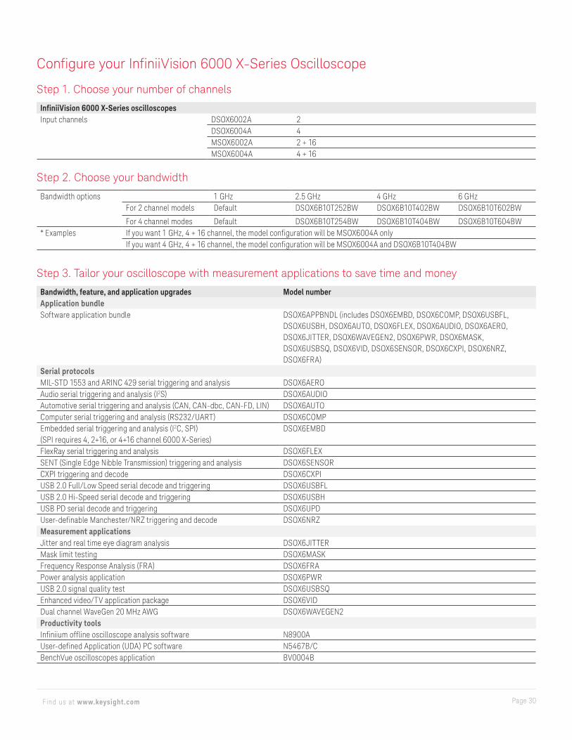
Designed for Touch. 12.1-inch capacitive multi-touch screen with gesture support sets a new visualization standard.
Not a touch screen fan? You can turn off the touch screen.
Zone touch trigger. If you can see it, you can trigger on it by drawing a zone box.
7-in-1 instrument sets a new integrationstandard: oscilloscope channels, digitalchannels, serial protocol analysis, dual- channel WaveGen, frequency responseanalysis, digital voltmeter, and 10-digitcounter-totalizer. Fully upgradable, includingbandwidth.
Standard color grade and histogram on a waveform, measurement, or math function adds statistical view.
Jitter and real-time eye diagram analysis is available for the first time ever in an embedded-OS-platform oscilloscope.
Dual-channel WaveGen function/arbitrary generator allows you to generate differential, clock and data, two channel modulation, and IQ signals. Modulation capability included.
Both USB keyboard and mouse are supported in 6000 X-Series for additional ease of use.
The portable oscilloscope class-leading 6 GHz upgradable bandwidth expands your application coverage including PCI Express.
New Standard for Price Performance: Bandwidth, Visualization, and Integration

Page 29Find us at www.keysight.com
Wide coverage of application and serial protocol solutions including USB 2.0 signal quality analysis.
Four AutoProbes (active and current probes) are supported simultaneously for demanding applications.
450,000 waveforms per second update rate minimizes the dead-time for maximum probability of capturing infrequent events and anomalies.
Multi-language voice control enables hands-free operation while you are holding probes.
Using docking panels with the capacitive touch screen adds a new dimension of usability. Move automatic measurements, cursors information, event lister, histogram, navigation, DVM, and the counter pane anywhere on the screen. Transparent panes are supported.
Standard advanced math displays four functions simultaneously for the most sophisticated signal analysis.
Display up to 10 measurements with statistics simultaneously without compromising other key information. Supports 56 automatic measurements and gating by cursors.
Industry’s only integrated digital voltmeter and 10-digit counter with totalizer.
Independent knobs per channel for fast operation. All front-panel knobs are push-able for access to common controls such as fine and coarse control.
Standard segment memory with event lister is powered by MegaZoom IV smart memory technology to intelligently capture only the signals of interest.
Page 30Find us at www.keysight.com
Step 1. Choose your number of channels
InfiniiVision 6000 X-Series oscilloscopesInput channels DSOX6002A 2
DSOX6004A 4MSOX6002A 2 + 16MSOX6004A 4 + 16
Step 2. Choose your bandwidth
Bandwidth options 1 GHz 2.5 GHz 4 GHz 6 GHzFor 2 channel models Default DSOX6B10T252BW DSOX6B10T402BW DSOX6B10T602BW
For 4 channel modes Default DSOX6B10T254BW DSOX6B10T404BW DSOX6B10T604BW* Examples If you want 1 GHz, 4 + 16 channel, the model configuration will be MSOX6004A only
If you want 4 GHz, 4 + 16 channel, the model configuration will be MSOX6004A and DSOX6B10T404BW
Step 3. Tailor your oscilloscope with measurement applications to save time and money
Bandwidth, feature, and application upgrades Model numberApplication bundleSoftware application bundle DSOX6APPBNDL (includes DSOX6EMBD, DSOX6COMP, DSOX6USBFL,
DSOX6USBH, DSOX6AUTO, DSOX6FLEX, DSOX6AUDIO, DSOX6AERO, DSOX6JITTER, DSOX6WAVEGEN2, DSOX6PWR, DSOX6MASK, DSOX6USBSQ, DSOX6VID, DSOX6SENSOR, DSOX6CXPI, DSOX6NRZ, DSOX6FRA)
Serial protocolsMIL-STD 1553 and ARINC 429 serial triggering and analysis DSOX6AEROAudio serial triggering and analysis (I2S) DSOX6AUDIOAutomotive serial triggering and analysis (CAN, CAN-dbc, CAN-FD, LIN) DSOX6AUTOComputer serial triggering and analysis (RS232/UART) DSOX6COMPEmbedded serial triggering and analysis (I2C, SPI)(SPI requires 4, 2+16, or 4+16 channel 6000 X-Series)
DSOX6EMBD
FlexRay serial triggering and analysis DSOX6FLEXSENT (Single Edge Nibble Transmission) triggering and analysis DSOX6SENSORCXPI triggering and decode DSOX6CXPIUSB 2.0 Full/Low Speed serial decode and triggering DSOX6USBFLUSB 2.0 Hi-Speed serial decode and triggering DSOX6USBHUSB PD serial decode and triggering DSOX6UPDUser-definable Manchester/NRZ triggering and decode DSOX6NRZMeasurement applicationsJitter and real time eye diagram analysis DSOX6JITTERMask limit testing DSOX6MASKFrequency Response Analysis (FRA) DSOX6FRAPower analysis application DSOX6PWRUSB 2.0 signal quality test DSOX6USBSQEnhanced video/TV application package DSOX6VIDDual channel WaveGen 20 MHz AWG DSOX6WAVEGEN2Productivity toolsInfiniium offline oscilloscope analysis software N8900AUser-defined Application (UDA) PC software N5467B/CBenchVue oscilloscopes application BV0004B
Configure your InfiniiVision 6000 X-Series Oscilloscope
Page 31Find us at www.keysight.com
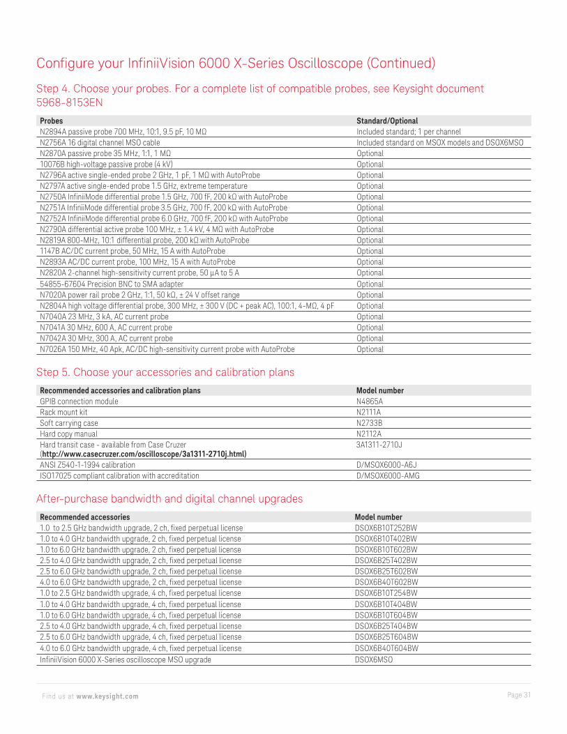
Step 4. Choose your probes. For a complete list of compatible probes, see Keysight document 5968-8153EN
Probes Standard/OptionalN2894A passive probe 700 MHz, 10:1, 9.5 pF, 10 MΩ Included standard; 1 per channelN2756A 16 digital channel MSO cable Included standard on MSOX models and DSOX6MSON2870A passive probe 35 MHz, 1:1, 1 MΩ Optional10076B high-voltage passive probe (4 kV) OptionalN2796A active single-ended probe 2 GHz, 1 pF, 1 MΩ with AutoProbe OptionalN2797A active single-ended probe 1.5 GHz, extreme temperature OptionalN2750A InfiniiMode differential probe 1.5 GHz, 700 fF, 200 kΩ with AutoProbe OptionalN2751A InfiniiMode differential probe 3.5 GHz, 700 fF, 200 kΩ with AutoProbe OptionalN2752A InfiniiMode differential probe 6.0 GHz, 700 fF, 200 kΩ with AutoProbe OptionalN2790A differential active probe 100 MHz, ± 1.4 kV, 4 MΩ with AutoProbe OptionalN2819A 800-MHz, 10:1 differential probe, 200 kΩ with AutoProbe Optional1147B AC/DC current probe, 50 MHz, 15 A with AutoProbe OptionalN2893A AC/DC current probe, 100 MHz, 15 A with AutoProbe OptionalN2820A 2-channel high-sensitivity current probe, 50 µA to 5 A Optional54855-67604 Precision BNC to SMA adapter OptionalN7020A power rail probe 2 GHz, 1:1, 50 kΩ, ± 24 V offset range OptionalN2804A high voltage differential probe, 300 MHz, ± 300 V (DC + peak AC), 100:1, 4-MΩ, 4 pF OptionalN7040A 23 MHz, 3 kA, AC current probe OptionalN7041A 30 MHz, 600 A, AC current probe OptionalN7042A 30 MHz, 300 A, AC current probe OptionalN7026A 150 MHz, 40 Apk, AC/DC high-sensitivity current probe with AutoProbe Optional
Step 5. Choose your accessories and calibration plans
Recommended accessories and calibration plans Model numberGPIB connection module N4865ARack mount kit N2111ASoft carrying case N2733BHard copy manual N2112AHard transit case - available from Case Cruzer(http://www.casecruzer.com/oscilloscope/3a1311-2710j.html)
3A1311-2710J
ANSI Z540-1-1994 calibration D/MSOX6000-A6JISO17025 compliant calibration with accreditation D/MSOX6000-AMG
After-purchase bandwidth and digital channel upgrades
Recommended accessories Model number1.0 to 2.5 GHz bandwidth upgrade, 2 ch, fixed perpetual license DSOX6B10T252BW1.0 to 4.0 GHz bandwidth upgrade, 2 ch, fixed perpetual license DSOX6B10T402BW1.0 to 6.0 GHz bandwidth upgrade, 2 ch, fixed perpetual license DSOX6B10T602BW2.5 to 4.0 GHz bandwidth upgrade, 2 ch, fixed perpetual license DSOX6B25T402BW2.5 to 6.0 GHz bandwidth upgrade, 2 ch, fixed perpetual license DSOX6B25T602BW4.0 to 6.0 GHz bandwidth upgrade, 2 ch, fixed perpetual license DSOX6B40T602BW1.0 to 2.5 GHz bandwidth upgrade, 4 ch, fixed perpetual license DSOX6B10T254BW1.0 to 4.0 GHz bandwidth upgrade, 4 ch, fixed perpetual license DSOX6B10T404BW1.0 to 6.0 GHz bandwidth upgrade, 4 ch, fixed perpetual license DSOX6B10T604BW2.5 to 4.0 GHz bandwidth upgrade, 4 ch, fixed perpetual license DSOX6B25T404BW2.5 to 6.0 GHz bandwidth upgrade, 4 ch, fixed perpetual license DSOX6B25T604BW4.0 to 6.0 GHz bandwidth upgrade, 4 ch, fixed perpetual license DSOX6B40T604BWInfiniiVision 6000 X-Series oscilloscope MSO upgrade DSOX6MSO
Configure your InfiniiVision 6000 X-Series Oscilloscope (Continued)
Page 32Find us at www.keysight.com
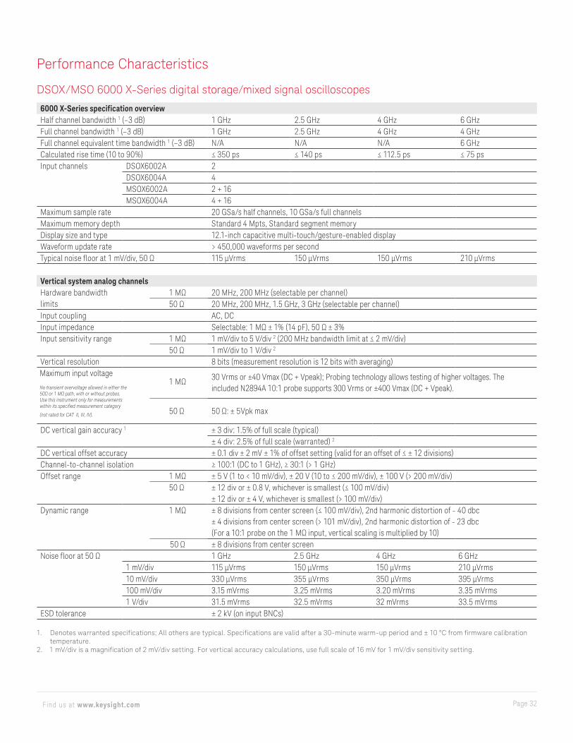
DSOX/MSO 6000 X-Series digital storage/mixed signal oscilloscopes
6000 X-Series specification overviewHalf channel bandwidth 1 (–3 dB) 1 GHz 2.5 GHz 4 GHz 6 GHzFull channel bandwidth 1 (–3 dB) 1 GHz 2.5 GHz 4 GHz 4 GHzFull channel equivalent time bandwidth 1 (–3 dB) N/A N/A N/A 6 GHzCalculated rise time (10 to 90%) ≤ 350 ps ≤ 140 ps ≤ 112.5 ps ≤ 75 psInput channels DSOX6002A 2
DSOX6004A 4MSOX6002A 2 + 16MSOX6004A 4 + 16
Maximum sample rate 20 GSa/s half channels, 10 GSa/s full channelsMaximum memory depth Standard 4 Mpts, Standard segment memoryDisplay size and type 12.1-inch capacitive multi-touch/gesture-enabled displayWaveform update rate > 450,000 waveforms per secondTypical noise floor at 1 mV/div, 50 Ω 115 μVrms 150 μVrms 150 μVrms 210 μVrms
Vertical system analog channelsHardware bandwidth limits
1 MΩ 20 MHz, 200 MHz (selectable per channel)50 Ω 20 MHz, 200 MHz, 1.5 GHz, 3 GHz (selectable per channel)
Input coupling AC, DCInput impedance Selectable: 1 MΩ ± 1% (14 pF), 50 Ω ± 3%Input sensitivity range 1 MΩ 1 mV/div to 5 V/div 2 (200 MHz bandwidth limit at ≤ 2 mV/div)
50 Ω 1 mV/div to 1 V/div 2
Vertical resolution 8 bits (measurement resolution is 12 bits with averaging)Maximum input voltage
No transient overvoltage allowed in either the 50Ω or 1 MΩ path, with or without probes. Use this instrument only for measurements within its specified measurement category
(not rated for CAT II, III, IV).
1 MΩ 30 Vrms or ±40 Vmax (DC + Vpeak); Probing technology allows testing of higher voltages. The included N2894A 10:1 probe supports 300 Vrms or ±400 Vmax (DC + Vpeak).
50 Ω 50 Ω: ± 5Vpk max
DC vertical gain accuracy 1 ± 3 div: 1.5% of full scale (typical)± 4 div: 2.5% of full scale (warranted) 2
DC vertical offset accuracy ± 0.1 div ± 2 mV ± 1% of offset setting (valid for an offset of ≤ ± 12 divisions)Channel-to-channel isolation ≥ 100:1 (DC to 1 GHz), ≥ 30:1 (> 1 GHz)Offset range 1 MΩ ± 5 V (1 to < 10 mV/div), ± 20 V (10 to ≤ 200 mV/div), ± 100 V (> 200 mV/div)
50 Ω ± 12 div or ± 0.8 V, whichever is smallest (≤ 100 mV/div)± 12 div or ± 4 V, whichever is smallest (> 100 mV/div)
Dynamic range 1 MΩ ± 8 divisions from center screen (≤ 100 mV/div), 2nd harmonic distortion of - 40 dbc± 4 divisions from center screen (> 101 mV/div), 2nd harmonic distortion of - 23 dbc(For a 10:1 probe on the 1 MΩ input, vertical scaling is multiplied by 10)
50 Ω ± 8 divisions from center screenNoise floor at 50 Ω 1 GHz 2.5 GHz 4 GHz 6 GHz
1 mV/div 115 µVrms 150 µVrms 150 µVrms 210 µVrms10 mV/div 330 µVrms 355 µVrms 350 µVrms 395 µVrms100 mV/div 3.15 mVrms 3.25 mVrms 3.20 mVrms 3.35 mVrms1 V/div 31.5 mVrms 32.5 mVrms 32 mVrms 33.5 mVrms
ESD tolerance ± 2 kV (on input BNCs)
1. Denotes warranted specifications; All others are typical. Specifications are valid after a 30-minute warm-up period and ± 10 °C from firmware calibration temperature.
2. 1 mV/div is a magnification of 2 mV/div setting. For vertical accuracy calculations, use full scale of 16 mV for 1 mV/div sensitivity setting.
Performance Characteristics
Page 33Find us at www.keysight.com
Performance Characteristics (Continued)
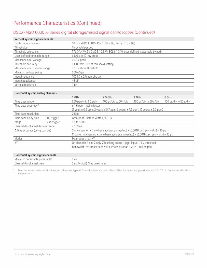
DSOX/MSO 6000 X-Series digital storage/mixed signal oscilloscopes (Continued)
Vertical system digital channelsDigital input channels 16 digital (D0 to D15. Pod 1: D7 ~ D0, Pod 2: D15 ~ D8)Thresholds Threshold per podThreshold selections TTL (+1.4 V), 5V CMOS (+2.5 V), ECL (–1.3 V), user-defined (selectable by pod)User-defined threshold range ± 8.0 V in 10-mV stepsMaximum input voltage ± 40 V peakThreshold accuracy 1 ± (100 mV + 3% of threshold setting)Maximum input dynamic range ± 10 V about thresholdMinimum voltage swing 500 mVppInput impedance 100 kΩ ± 2% at probe tipInput capacitance ~8 pFVertical resolution 1 bit
Horizontal system analog channels1 GHz 2.5 GHz 4 GHz 6 GHz
Time base range 500 ps/div to 50 s/div 100 ps/div to 50 s/div 100 ps/div to 50 s/div 100 ps/div to 50 s/divTime base accuracy 1 ± 1.6 ppm + aging factor
(1 year: ± 0.5 ppm, 2 years: ± 0.7 ppm, 5 years: ± 1.5 ppm, 10 years: ± 2.0 ppm)Time base resolution 2.5 psTime base delay time range
Pre-trigger Greater of 1 screen width or 50 µsPost-trigger 1 s to 500 s
Channel-to-channel deskew range ± 100 nsΔ time accuracy (using cursors) Same channel: ± (time base accuracy x reading) ± (0.0016 x screen width) ± 10 ps
Channel-to-channel: ± (time base accuracy x reading) ± (0.0016 x screen width) ± 15 psModes Main, zoom, roll, XYXY On channels 1 and 2 only. Z blanking on ext trigger input, 1.4 V threshold
Bandwidth: maximum bandwidth. Phase error at 1 MHz: < 0.5 degree
Horizontal system digital channelsMinimum detectable pulse width 2 nsChannel-to-channel skew 2 ns (typical); 3 ns (maximum)
1. Denotes warranted specifications; All others are typical. Specifications are valid after a 30-minute warm-up period and ± 10 °C from firmware calibration temperature.
Page 34Find us at www.keysight.com
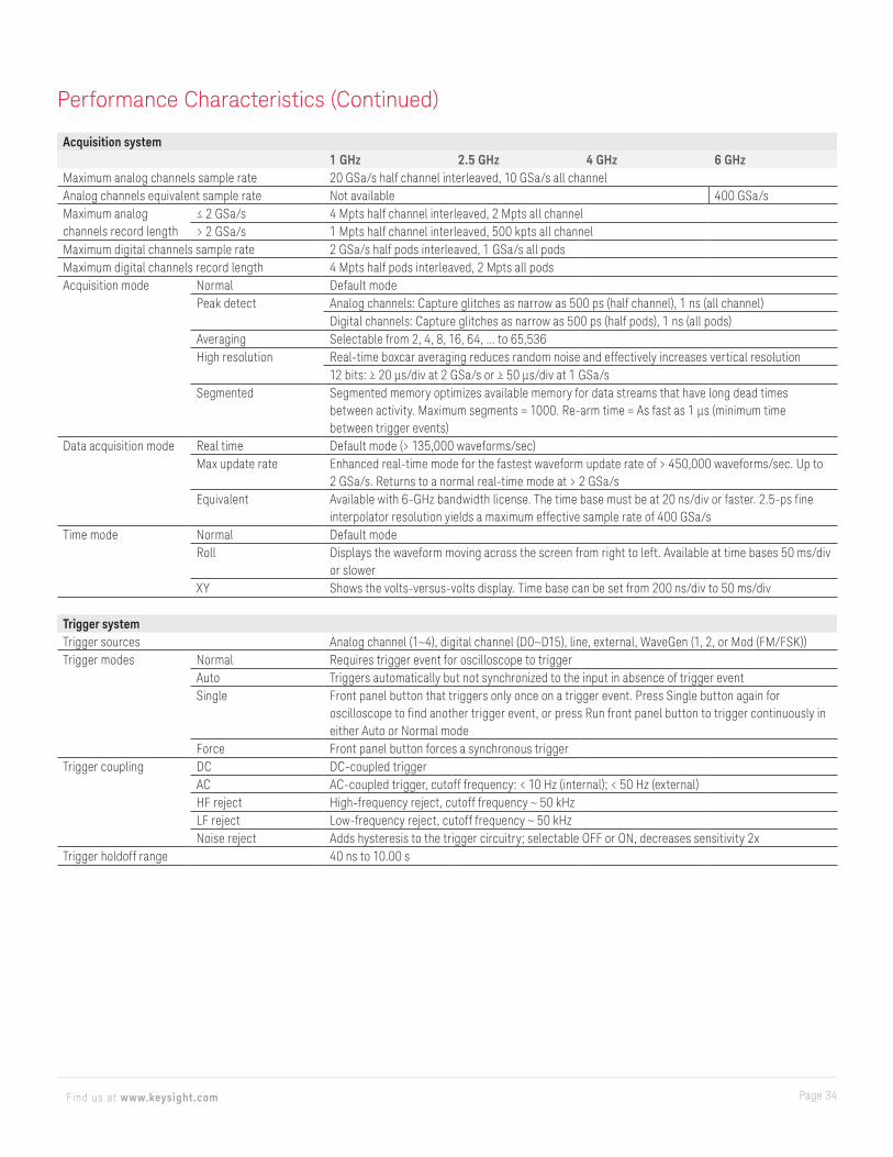
Acquisition system1 GHz 2.5 GHz 4 GHz 6 GHz
Maximum analog channels sample rate 20 GSa/s half channel interleaved, 10 GSa/s all channelAnalog channels equivalent sample rate Not available 400 GSa/sMaximum analog channels record length
≤ 2 GSa/s 4 Mpts half channel interleaved, 2 Mpts all channel> 2 GSa/s 1 Mpts half channel interleaved, 500 kpts all channel
Maximum digital channels sample rate 2 GSa/s half pods interleaved, 1 GSa/s all podsMaximum digital channels record length 4 Mpts half pods interleaved, 2 Mpts all podsAcquisition mode Normal Default mode
Peak detect Analog channels: Capture glitches as narrow as 500 ps (half channel), 1 ns (all channel)Digital channels: Capture glitches as narrow as 500 ps (half pods), 1 ns (all pods)
Averaging Selectable from 2, 4, 8, 16, 64, ... to 65,536High resolution Real-time boxcar averaging reduces random noise and effectively increases vertical resolution
12 bits: ≥ 20 μs/div at 2 GSa/s or ≥ 50 μs/div at 1 GSa/sSegmented Segmented memory optimizes available memory for data streams that have long dead times
between activity. Maximum segments = 1000. Re-arm time = As fast as 1 μs (minimum time between trigger events)
Data acquisition mode Real time Default mode (> 135,000 waveforms/sec)Max update rate Enhanced real-time mode for the fastest waveform update rate of > 450,000 waveforms/sec. Up to
2 GSa/s. Returns to a normal real-time mode at > 2 GSa/sEquivalent Available with 6-GHz bandwidth license. The time base must be at 20 ns/div or faster. 2.5-ps fine
interpolator resolution yields a maximum effective sample rate of 400 GSa/sTime mode Normal Default mode
Roll Displays the waveform moving across the screen from right to left. Available at time bases 50 ms/div or slower
XY Shows the volts-versus-volts display. Time base can be set from 200 ns/div to 50 ms/div
Trigger systemTrigger sources Analog channel (1~4), digital channel (D0~D15), line, external, WaveGen (1, 2, or Mod (FM/FSK))Trigger modes Normal Requires trigger event for oscilloscope to trigger
Auto Triggers automatically but not synchronized to the input in absence of trigger eventSingle Front panel button that triggers only once on a trigger event. Press Single button again for
oscilloscope to find another trigger event, or press Run front panel button to trigger continuously in either Auto or Normal mode
Force Front panel button forces a synchronous triggerTrigger coupling DC DC-coupled trigger
AC AC-coupled trigger, cutoff frequency: < 10 Hz (internal); < 50 Hz (external)HF reject High-frequency reject, cutoff frequency ~ 50 kHzLF reject Low-frequency reject, cutoff frequency ~ 50 kHzNoise reject Adds hysteresis to the trigger circuitry; selectable OFF or ON, decreases sensitivity 2x
Trigger holdoff range 40 ns to 10.00 s
Performance Characteristics (Continued)

Page 35Find us at www.keysight.com
Trigger systemTrigger jitter < 1.0-ps rms with the jitter-free trigger
< 3.0-ps rms without the jitter-free triggerTrigger bandwidth Edge 500 MHz, 1 GHz, 2.5 GHz models: bandwidth of oscilloscope. 4-GHz and 6-GHz models: 3.5 GHz
Other modes Bandwidth of oscilloscope or 1 GHz, whichever is smallerTrigger sensitivity (internal) 1
1 GHz bandwidth ≤ 10 mV/div DC to 1 GHz Greater of 1 div or 5 mVpp> 10 mV/div DC to 1 GHz 0.6 div
2.5, 4, and 6 GHz bandwidth
≤ 10 mV/div DC to 2 GHz Greater of 1 div or 5 mVpp2.0 to 3.5 GHz Greater of 1.5 div or 5 mVpp
> 10 mV/div DC to 2 GHz 0.6 div2.0 to 3.5 GHz 1.0 div
Trigger sensitivity (external) 1
± 1.6 V 40 mVpp DC to 100 MHz, 70 mVpp 100 to 200 MHz± 8 V 200 mVpp DC to 100 MHz, 350 mVpp 100 to 200 MHz
Trigger level range Any channel ± 6 div from center screenExternal 8-V range = ± 8 V; 1.6-V range = ± 1.6 V
1. Denotes warranted specifications; All others are typical. Specifications are valid after a 30-minute warm-up period and ± 10 °C from firmware calibration temperature.
Trigger type selectionsInfiniiScan Zone (hardware zone qualifier) Trigger on user-defined zones drawn on the display. Applies to one analog channel at a time.
Specify zones as either “must intersect” or “must not intersect.” Up to two zones. > 160,000 wfm/sec update rateSupported modes: Normal, peak detect, high resolution, max update rateAlso works simultaneously with the serial decodes and mask/limit test
Edge Trigger on a rising and falling edge of any source, alternating or either edge of analog and digital channels
Edge then edge (B trigger) Arm on a selected edge, wait a specified time, then trigger on a specified count of another selected edge. Minimum 4 ns
Pulse width Trigger on a pulse on a selected channel, whose time duration is less than a value, greater than a value, or inside a time range
– Minimum duration setting: 2 ns – Maximum duration setting: 10 s – Range minimum: 10 ns
Pattern Trigger when a specified pattern of high, low, and don’t-care levels on any combination of analog, digital, or trigger channels is [entered | exited]. Pattern must have stabilized for a minimum of 2 ns to qualify as a valid trigger condition
– Minimum duration setting: 2 ns – Maximum duration setting: 10 s
Or Trigger on any selected edges from available sources (analog and digital channels only).Bandwidth is 500 MHz
Performance Characteristics (Continued)
Page 36Find us at www.keysight.com
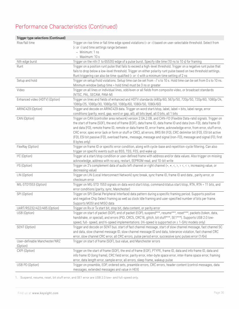
Trigger type selections (Continued)Rise/fall time Trigger on rise time or fall time edge speed violations (< or >) based on user-selectable threshold. Select from
(< or >) and time settings range between – Minimum: 1 ns – Maximum: 10 s
Nth edge burst Trigger on the nth (1 to 65535) edge of a pulse burst. Specify idle time (10 ns to 10 s) for framingRunt Trigger on a position runt pulse that fails to exceed a high-level threshold. Trigger on a negative runt pulse that
fails to drop below a low-level threshold. Trigger on either polarity runt pulse based on two threshold settings. Runt triggering can also be time-qualified (< or >) with a minimum time setting of 2 ns
Setup and hold Trigger on setup/hold violations. Setup time can be set from –7 s to 10 s. Hold time can be set from 0 s to 10 ns. Minimum window (setup time + hold time) must be 3 ns or greater
Video Trigger on all lines or individual lines, odd/even or all fields from composite video, or broadcast standards (NTSC, PAL, SECAM, PAM-M)
Enhanced video (HDTV) (Option) Trigger on lines and fields of enhanced and HDTV standards (480p/60, 567p/50, 720p/50, 720p/60, 1080p/24, 1080p/25, 1080p/30, 1080p/50, 1080p/60, 1080i/50, 1080i/60)
ARINC429 (Option) Trigger and decode on ARINC429 data. Trigger on word start/stop, label, label + bits, label range, error conditions (parity, word, gap, word or gap, all), all bits (eye), all 0 bits, all 1 bits
CAN (Option) Trigger on CAN (controller area network) version 2.0A,2.0B, and CAN-FD (Flexible Data-rate) signals. Trigger on the start of frame (SOF), the end of frame (EOF), data frame ID, data frame ID and data (non-FD), data frame ID and data (FD), remote frame ID, remote or data frame ID, error frame, acknowledge error, from error, stuff error, CRC error, spec error (ack or form or stuff or CRC), all errors, BRS Bit (FD), CRC delimiter bit (FD), ESI bit active (FD), ESI bit passive (FD), overload frame., message, message and signal (non-FD), message and signal (FD, first 8 bytes only)
FlexRay (Option) Trigger on frame ID or specific error condition, along with cycle-base and repetition-cycle filtering. Can also trigger on specific events such as BSS, TSS, FES, and wake up
I²C (Option) Trigger at a start/stop condition or user-defined frame with address and/or data values. Also trigger on missing acknowledge, address with no acq, restart, EEPROM read, and 10-bit write
I²S (Option) Trigger on 2’s complement data of audio left channel or right channel (=, ≠, <, >, > <, < >, increasing value, or decreasing value)
LIN (Option) Trigger on LIN (Local Interconnect Network) sync break, sync frame ID, frame ID and data , parity error, or checksum error
MIL-STD1553 (Option) Trigger on MIL-STD 1553 signals on data word start/stop, command/status start/stop, RTA, RTA + 11 bits, and error conditions (parity, sync, Manchester)
SPI (Option) Trigger on SPI (Serial Peripheral Interface) data pattern during a specific framing period. Supports positive and negative Chip Select framing as well as clock Idle framing and user-specified number of bits per frame. Supports MOSI and MISO data
UART/RS232/422/485 (Option) Trigger on Rx or Tx start bit, stop bit, data content, or parity errorUSB (Option) Trigger on start of packet (SOP), end of packet (EOP), suspend***, resume***, reset***, packets (token, data,
handshake, or special), and errors (PID, CRC5, CRC16, glitch, bit stuff***, SE1***). Supports USB 2.0 low-speed, full- speed, and hi-speed implementations. (Hi-speed is supported on ≥ 1-GHz models only)
SENT (Option) Trigger and decode on SENT bus. start of fast channel message, start of slow channel message, fast channel SC and data, slow channel message ID, slow channel message ID and data, tolerance violation, fast channel CRC error, slow channel CRC error, all CRC errors, pulse period error, successive sync pulses error (1/64)
User-definable Manchester/NRZ (Option)
Trigger on start of frame (SOF), bus value, and Manchester errors
CXPI (Option) Trigger on the start of frame (SOF), the end of frame (EOF), PTYPE, frame ID, data and info frame ID, data and info frame ID (long frame), CRC field error, parity error, inter-byte space error, inter-frame space error, framing error, data length error, sample error, all errors, sleep frame, wakeup pulse
USB PD (Option) Trigger on preamble, EDP, ordered sets, preamble errors, CRC errors, header content (control messages, data messages, extended messages and value in HEX)
1. Suspend, resume, reset, bit stuff error, and SE1 error are USB 2.0 low- and full-speed only.
Performance Characteristics (Continued)
Page 37Find us at www.keysight.com
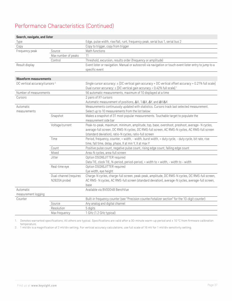
Search, navigate, and listerType Edge, pulse width, rise/fall, runt, frequency peak, serial bus 1, serial bus 2Copy Copy to trigger, copy from triggerFrequency peak Source Math functions
Max number of peaks 11Control Threshold, excursion, results order (frequency or amplitude)
Result display Event lister or navigation. Manual or autoscroll via navigation or touch event lister entry to jump to a specific event
Waveform measurementsDC vertical accuracy/cursors 2 Single cursor accuracy: ± [DC vertical gain accuracy + DC vertical offset accuracy + 0.21% full scale]
Dual cursor accuracy: ± [DC vertical gain accuracy + 0.42% full scale] 1
Number of measurements 56 automatic measurements, maximum of 10 displayed at a timeCursors 2 pairs of XY cursors
Automatic measurement of positions, ΔX, 1/ΔX, ΔY, and ΔY/ΔXAutomatic measurements
Measurements continuously updated with statistics. Cursors track last selected measurement. Select up to 10 measurements from the list below:
Snapshot Makes a snapshot of 31 most popular measurements. Touchable target to populate the measurement side bar
Voltage/current Peak-to-peak, maximum, minimum, amplitude, top, base, overshoot, preshoot, average- N cycles, average-full screen, DC RMS-N cycles, DC RMS-full screen, AC RMS-N cycles, AC RMS-full screen (standard deviation), ratio-N cycles, ratio-full screen
Time Period, frequency, counter, + width, - width, burst width, + duty cycle, - duty cycle, bit rate, rise time, fall time, delay, phase, X at min Y, X at max Y
Count Positive pulse count, negative pulse count, rising edge count, falling edge countMixed Area-N cycles, area-full screenJitter Option DSOX6JITTER required
Data TIE, clock TIE, N-period, period-period, + width to + width, - width to - widthReal-time eye Option DSOX6JITTER required
Eye width, eye heightDual-channel (requires N2820A probe)
Charge-N cycles, charge-full screen, peak-peak, amplitude, DC RMS-N cycles, DC RMS-full screen, AC RMS- N cycles, AC RMS-full screen (standard deviation), average-N cycles, average-full screen, base
Automatic measurement logging
Available via BV0004B BenchVue
Counter Built-in frequency counter (see “Precision counter/totalizer section” for the 10-digit counter)Source Any analog and digital channelResolution 5 digitsMax frequency 1 GHz (1.2 GHz typical)
1. Denotes warranted specifications; All others are typical. Specifications are valid after a 30-minute warm-up period and ± 10 °C from firmware calibration temperature.
2. 1 mV/div is a magnification of 2 mV/div setting. For vertical accuracy calculations, use full scale of 16 mV for 1 mV/div sensitivity setting.
Performance Characteristics (Continued)
Page 38Find us at www.keysight.com
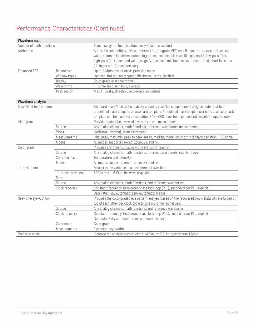
Waveform mathNumber of math functions Four, displays all four simultaneously. Can be cascadedArithmetic Add, subtract, multiply, divide, differentiate, integrate, FFT, Ax + B, squared, square root, absolute
value, common logarithm, natural logarithm, exponential, base 10 exponential, low-pass filter, high-pass filter, averaged value, magnify, max hold, min hold, measurement trend, chart logic bus (timing or state), clock recovery
Enhanced FFT Record size Up to 1-Mpts resolution via precision modeWindow types Hanning, flat top, rectangular, Blackman-Harris, BartlettDisplay Color grade or monochromeWaveforms FFT, max hold, min hold, averagePeak search Max 11 peaks, threshold and excursion control
Waveform analysisMask/limit test (Option) Standard mask/limit test capability provides pass/fail comparison of a signal under test to a
predefined mask template or automask template. Predefined mask templates or edits to an automask template can be made via a text editor. > 130,000 mask tests per second (waveform update rate)
Histogram Provides a statistical view of a waveform or a measurementSource Any analog channels, math functions, reference waveforms, measurementsTypes Horizontal, vertical, or measurementMeasurements Hits, peak, max, min, peak to peak, mean, median, mode, bin width, standard deviation, 1~3 sigmaModes All modes supported except zoom, ZY, and roll
Color grade Provides a 3-dimensional view of waveform intensitySource Any analog channels, math functions, reference waveforms, real-time eyeColor themes Temperature and intensityModes All modes supported except zoom, ZY, and roll
Jitter (Option) Measures the variance of a measurement over timeJitter measurement floor
600 fs rms at 6 GHz sine wave (typical)
Source Any analog channels, math functions, and reference waveformsClock recovery Constant frequency, first-order phase lock loop (PLL), second-order PLL, explicit
Data rate: Fully automatic, semi-automatic, manualReal-time eye (Option) Provides the color graded eye pattern analysis based on the recovered clock. Data bits are folded on
top of each other per clock cycle to give a 3-dimensional viewSource Any analog channels, math functions, and reference waveformsClock recovery Constant frequency, first-order phase lock loop (PLL), second-order PLL, explicit
Data rate: Fully automatic, semi-automatic, manualColor mode Color gradeMeasurements Eye height, eye width
Precision mode Increase the analysis record length. Minimum: 100 kpts; maximum 1 Mpts
Performance Characteristics (Continued)
Page 39Find us at www.keysight.com
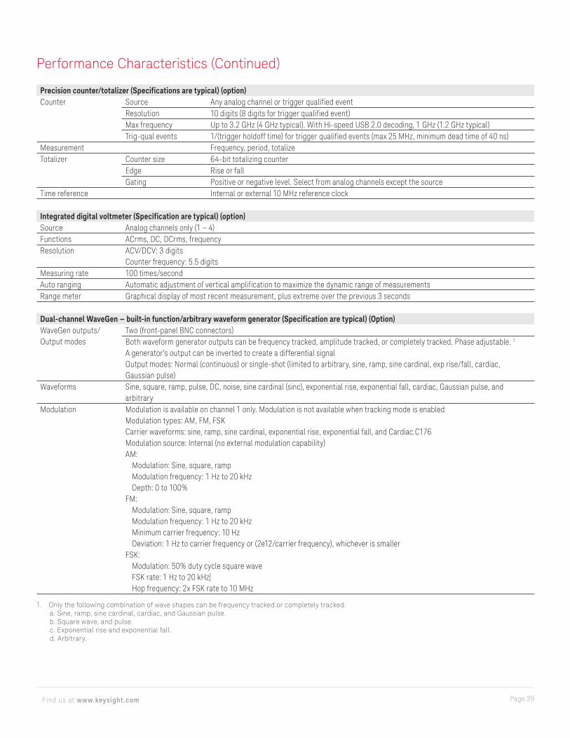
Precision counter/totalizer (Specifications are typical) (option)Counter Source Any analog channel or trigger qualified event
Resolution 10 digits (8 digits for trigger qualified event)Max frequency Up to 3.2 GHz (4 GHz typical). With Hi-speed USB 2.0 decoding, 1 GHz (1.2 GHz typical)Trig-qual events 1/(trigger holdoff time) for trigger qualified events (max 25 MHz, minimum dead time of 40 ns)
Measurement Frequency, period, totalizeTotalizer Counter size 64-bit totalizing counter
Edge Rise or fallGating Positive or negative level. Select from analog channels except the source
Time reference Internal or external 10 MHz reference clock
Integrated digital voltmeter (Specification are typical) (option)Source Analog channels only (1 ~ 4)Functions ACrms, DC, DCrms, frequencyResolution ACV/DCV: 3 digits
Counter frequency: 5.5 digitsMeasuring rate 100 times/secondAuto ranging Automatic adjustment of vertical amplification to maximize the dynamic range of measurementsRange meter Graphical display of most recent measurement, plus extreme over the previous 3 seconds
Dual-channel WaveGen — built-in function/arbitrary waveform generator (Specification are typical) (Option)WaveGen outputs/Output modes
Two (front-panel BNC connectors)Both waveform generator outputs can be frequency tracked, amplitude tracked, or completely tracked. Phase adjustable. 1
A generator’s output can be inverted to create a differential signalOutput modes: Normal (continuous) or single-shot (limited to arbitrary, sine, ramp, sine cardinal, exp rise/fall, cardiac, Gaussian pulse)
Waveforms Sine, square, ramp, pulse, DC, noise, sine cardinal (sinc), exponential rise, exponential fall, cardiac, Gaussian pulse, and arbitrary
Modulation Modulation is available on channel 1 only. Modulation is not available when tracking mode is enabledModulation types: AM, FM, FSKCarrier waveforms: sine, ramp, sine cardinal, exponential rise, exponential fall, and Cardiac.C176Modulation source: Internal (no external modulation capability)AM:
Modulation: Sine, square, rampModulation frequency: 1 Hz to 20 kHzDepth: 0 to 100%
FM:Modulation: Sine, square, rampModulation frequency: 1 Hz to 20 kHzMinimum carrier frequency: 10 HzDeviation: 1 Hz to carrier frequency or (2e12/carrier frequency), whichever is smaller
FSK:Modulation: 50% duty cycle square waveFSK rate: 1 Hz to 20 kHz|Hop frequency: 2x FSK rate to 10 MHz
1. Only the following combination of wave shapes can be frequency tracked or completely tracked:a. Sine, ramp, sine cardinal, cardiac, and Gaussian pulse.b. Square wave, and pulse.c. Exponential rise and exponential fall.d. Arbitrary.
Performance Characteristics (Continued)

Page 40Find us at www.keysight.com
Dual-channel WaveGen — built-in function/arbitrary waveform generator (Specification are typical) (Continued)Sine Frequency range 0.1 Hz to 20 MHz
Amplitude flatness ± 0.5 dB (relative to 1 kHz)Harmonic distortion –40 dBcSpurious (nonharmonics) –40 dBcTotal harmonic distortion 1%SNR (50 Ω load, 500 MHz BW) 40 dB (Vpp ≥ 0.1 V); 30 dB (Vpp < 0.1V)
Square wave/pulse Frequency range 0.1 Hz to 10 MHzDuty cycle 20 to 80%Duty cycle resolution Larger of 1% or 10 nsRise/fall time 19 ns (10 to 90%)Overshoot < 2%Asymmetry (at 50% DC) ± 1% ± 5 nsJitter (TIE RMS) 500 ps
Ramp/triangle wave Frequency range 0.1 Hz to 200 kHzLinearity 1%Variable symmetry 0 to 100%Symmetry resolution 1%
Pulse Frequency range 0.1 Hz to 10 MHzPulse width 20 ns minimumPulse with resolution 10 nsEdge time Fixed at 19 ns (not variable)Overshoot < 2%
Noise Bandwidth 20 MHz typicalSine cardinal (sinc) Frequency range 0.1 Hz to 1.0 MHzExponential rise/fall Frequency range 0.1 Hz to 5.0 MHzCardiac Frequency range 0.1 Hz to 200.0 kHzGaussian pulse Frequency range 0.1 Hz to 5.0 MHzArbitrary Waveform length 1 to 8,192 points
Amplitude resolution 10 bits (including sign bit) 1
Repetition rate 0.1 Hz to 12 MHzSample rate 100 MSa/sFilter bandwidth 20 MHz
Frequency Sine wave and ramp accuracy 130 ppm (frequency < 10 kHz)50 ppm (frequency > 10 kHz)
Square wave and pulse accuracy [50 + frequency/200] ppm (frequency < 25 kHz)50 ppm (frequency ≥ 25 kHz)
Resolution 0.1 Hz or 4 digits, whichever is larger
1. Full resolution is not available at output due to internal attenuator stepping.
Performance Characteristics (Continued)
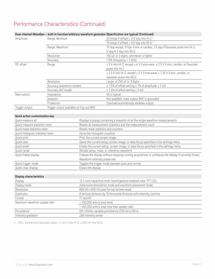
Page 41Find us at www.keysight.com
Dual-channel WaveGen — built-in function/arbitrary waveform generator (Specification are typical) (Continued)Amplitude Range: Minimum 20 mVpp if |offset| ≤ 0.5 Vpp into Hi-Z 1
10 mVpp if |offset| ≤ 0.5 Vpp into 50 Ω 1
Range: Maximum 10 Vpp except, 9 Vpp if sinc or cardiac, 7.5 Vpp if Gaussian pulse into Hi-Z; 5 Vpp/4.5 Vpp into 50 Ω
Resolution 100 μV or 3 digits, whichever is higherAccuracy 1.5% (frequency = 1 kHz)
DC offset Range ± 5 V into Hi-Z, except ± 4 V if sine wave, ± 2.5 V if sinc, cardiac, or Gaussian pulse into Hi-Z± 2.5 V into Hi-Z, except ± 2 V if sine wave, ± 1.25 V if sinc, cardiac, or Gaussian pulse into 50 Ω
Resolution Larger of 250 uV or 3 digitsAccuracy (waveform modes) ± 1.5% of offset setting ± 1% of amplitude ± 1 mVAccuracy (DC mode) ± 1.5% of offset setting ± 3 mV
Main output Impedance 50 Ω typicalIsolation Not available, main output BNC is groundedProtection Overload automatically disables output
Trigger output Trigger output available on trig-out BNC
Quick action customization keyQuick measure all Displays a popup containing a snapshot of all the single waveform measurementsQuick measure statistics reset Resets all measurement statistics and the measurement countQuick mask statistics reset Resets mask statistics and countersQuick histogram statistics reset Zeros the histogram countersQuick print Print the current screen imageQuick save Saves the current setup, screen image, or data file as specified in the settings menuQuick email Emails the current setup, screen image, or data file as specified in the settings menuQuick recall Recalls setup, mask, or reference waveformQuick freeze display Freezes the display without stopping running acquisitions or unfreezes the display if currently frozen.
Waveform intensity preservedQuick trigger mode Toggles the trigger mode between auto and normalQuick clear display Clears the display
Display characteristicsDisplay 12.1-inch capacitive multi-touch/gesture enabled color TFT LCDDisplay mode Zone/zoom/annotation mode and waveform placement modeResolution 800 (H) x 600 (V) pixel format (screen area)Graticules 8 vertical divisions by 10 horizontal divisions with intensity controlsFormat YT and XYMaximum waveform update rate > 135,000 wfm/s (real time)
> 450,000 wfm/s (real time max update rate)Persistence Off, infinite, variable persistence (100 ms to 60 s)Intensity gradation 256 intensity levels
1. Sinc, cardiac and Gaussian pulse: ± 1.25 V into Hi-Z; ± 625 mV into 50 Ω.
Performance Characteristics (Continued)

Page 42Find us at www.keysight.com
ConnectivityUSB 2.0 hi-speed host port USB 2.0 hi-speed host ports x3, two front and one real panel. Supports memory devices, printers, keyboards, mice,
and USB microphonesUSB 2.0 hi-speed device port One USB 2.0 hi-speed device port on rear panel. USB Test and Measurement Class (USBTMC) compatibleLAN port 10/100/1000 Base-T port on rear panel. LXI IPv6 extended functionWeb remote control VNC Web interface (via major Web browsers)Video-out port VGA out on rear panel. Connect oscilloscope display to an external monitor or projectorGPIB port N4865A GPIB-to-LAN adapter (option)10-MHz reference BNC connector on the rear panel
Support mode Output and input off, output on (10-MHz out) input on (10-MHz in)In mode 50 Ω, 356 mVpp to 4.48 Vpp (–5 dBm to 17 dBm), 6.32-Vpp max (20-dBm max)
Recommended input signal accuracy: better than ± 10 ppmOut mode 50 Ω, 1.65 Vpp square wave
Trigger out BNC connector on the rear panel. Supported modes: triggers, mask, waveform generator 1 sync pulse, and waveform generator 2 sync pulse
General and environmental characteristicsPower line consumption Maximum 200 WPower voltage range 100-120 V, 50/60/400 Hz; 100-240 V, 50/60 HzEnvironmental rating 0 to +50 °C; 3962 m Max
Maximum Relative Humidity (non-condensing): 80%RH up to 40 °C, decreases linearly to 50%RH at 50 °CFrom 40 °C to 50 °C, the maximum % Relative Humidity follows the line of constant dew point
Electromagnetic compatibility Meets EMC Directive (2004/108/EC), meets or exceeds IEC 61326-1:2005/EN61326-1:2006 Group 1 Class A requirementCISPR 11/EN 55011IEC 61000-4-2/EN 61000-4-2IEC 61000-4-3/EN 61000-4-3IEC 61000-4-4/EN 61000-4-4IEC 61000-4-5/EN 61000-4-5IEC 61000-4-6/EN 61000-4-6IEC 61000-4-11/EN 61000-4-11Canada: ICES-001:2004Australia/New Zealand: AS/NZS
Safety ANSI/UL Std. No. 61010-1:2012; CAN/CSA-C22.2 No. 61010-1-12Vibration Meets IEC60068-2-6 and MIL-PRF-28800; class 3 randomShock Meets IEC 60068-2-27 and MIL-PRF-28800; class 3 random; (operating 30 g, ½ sine, 11-ms duration,
3 shocks/axis along major axis, total of 18 shocks)Mean Time Before Failure (MTBF) > 120,000 hoursDimensions 425 mm W x 288 mm H x 148 mm DWeight Net: 6.8 kg (15 lbs.), Shipping: 11.3 kg (25 lbs.)
Performance Characteristics (Continued)

Page 43Find us at www.keysight.com
Non-volatile storageReference waveform display Four internal waveforms or USB thumb drive. Displays up to 4 reference waveforms simultaneouslyData/file save Setup/image Setup (*.scp), 8 or 24-bit bitmap image (*.bmp), PNG 24-bit image (*.png)
Waveform data CSV data (*.csv), ASCII XY data (*.csv), binary data (*.bin), lister data (*.csv), reference waveform data (*.h5), multichannel waveform data (*.h5), arbitrary waveform data (*.csv)
Application data Mask (*.msk), power harmonics data (*.csv), USB signal quality (*.html and *.bmp)Analysis results (*.csv) Cursor data, measurement results, histogram statistics, mask test statistics, color grade bin,
search, segmented timestampsMax USB flash drive size Supports industry standard flash drivesSet ups without USB flash drive 10 internal setupsSet ups with USB flash drive Limited by size of USB drive
Included standard with oscilloscopeCalibration Certificate of calibration, 2-year calibration intervalProbe One per channel, N2894A 700-MHz passive probe (10:1 attenuation)
N2756A 16-digital-channel MSO cable (1 per oscilloscope included on all MSO models and DSOX6MSO upgrade option)
Interface language support/built-in help English, Chinese (simplified and traditional), French, German, Italian, Japanese, Korean, Portuguese, Russian, and Spanish localized front-panel overlays, interface, and built-in help system
Voice control support English (American), English (British), English (Indian), Chinese Simplified (Mainland), Chinese Simplified (Cantonese), Chinese Traditional (Taiwan), Chinese Traditional (Cantonese), French, German, Italian, Japanese, Korean, Portuguese, Russian, Spanish (Latin America) and Spanish (Castilian)
Power cord Localized power cordFront-panel protection Front-panel coverDocumentation CD containing localized user’s guide, service guide, and programmer’s manual
Related literature
Publication title Publication numberJitter Analysis - Application Note 5991-4000ENAutomotive Serial Bus Testing Using Keysight’s InfiniiVision X-Series and Infiniium S-Series Oscilloscopes - Application Note 5991-4038ENPhysical Layer Testing of the USB 2.0 Serial Bus Using InfiniiVision 6000 X-Series and Infiniium Series Oscilloscopes - Application Note
5991-4167EN
Evaluating Oscilloscopes for Low-Power Measurements - Application Note 5991-4268ENInfiniiVision and Infiniium Oscilloscopes - Product Fact Sheet 5991-4273ENEvaluating Current Probe Technologies for Low-Power Measurements - Application Note 5991-4375EN
Performance Characteristics (Continued)
44 | Keysight | InfiniiVision 6000 X-Series Oscilloscopes - Data Sheet
www.axiestandard.orgAdvancedTCA® Extensions for Instrumentation and Test (AXIe) is an open standard that extends the AdvancedTCA for general purpose and semiconductor test. The business that became Keysight was a founding member of the AXIe consortium. ATCA®, AdvancedTCA®, and the ATCA logo are registered US trademarks of the PCI Industrial Computer Manufacturers Group.
www.lxistandard.org
LAN eXtensions for Instruments puts the power of Ethernet and the Web inside your test systems. The business that became Keysight was a founding member of the LXI consortium.
www.pxisa.org
PCI eXtensions for Instrumentation (PXI) modular instrumentation delivers a rugged, PC-based high-performance measurement and automation system.
Learn more atwww.keysight.com/find/software
Start with a 30-day free trial.www.keysight.com/find/free_trials
Download your next insightKeysight software is downloadable
expertise. From first simulation through
first customer shipment, we deliver the
tools your team needs to accelerate from
data to information to actionable insight.
– Electronic design automation (EDA)
software
– Application software
– Programming environments
– Productivity software
Page 44Find us at www.keysight.com This information is subject to change without notice. © Keysight Technologies, 2018-2019, Published in USA, November 6, 2019, 5991-4087EN
Learn more at: www.keysight.comFor more information on Keysight Technologies’ products, applications or services,
please contact your local Keysight office. The complete list is available at:
www.keysight.com/find/contactus