Embed Size (px)
Citation preview
M A G E N K E G L E Y , T A Y L O R C O N L E Y , G U Y B A R K E R , M A T T G A L L A G H E R
INFINITE VERMICASTSOLUTIONS
ABOUT THE CLIENT
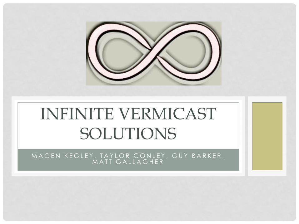
• Dale Robinson
• Inventor of The Big Squeegee
• http://www.bigsqueegee.com
• Runs business out of Lawton, OK
• Looking to innovate vermicomposting systems by
making them continuous
Bigsqueegee.com
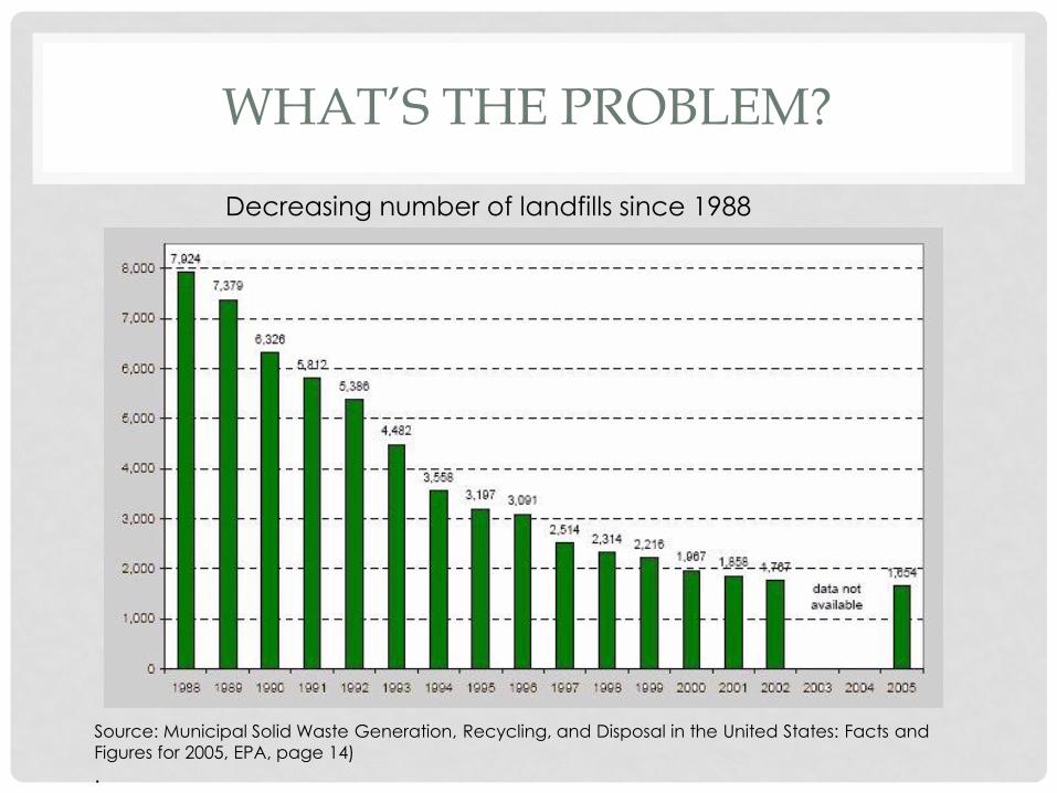
WHAT’S THE PROBLEM?
Source: Municipal Solid Waste Generation, Recycling, and Disposal in the United States: Facts and
Figures for 2005, EPA, page 14)
.
Decreasing number of landfills since 1988
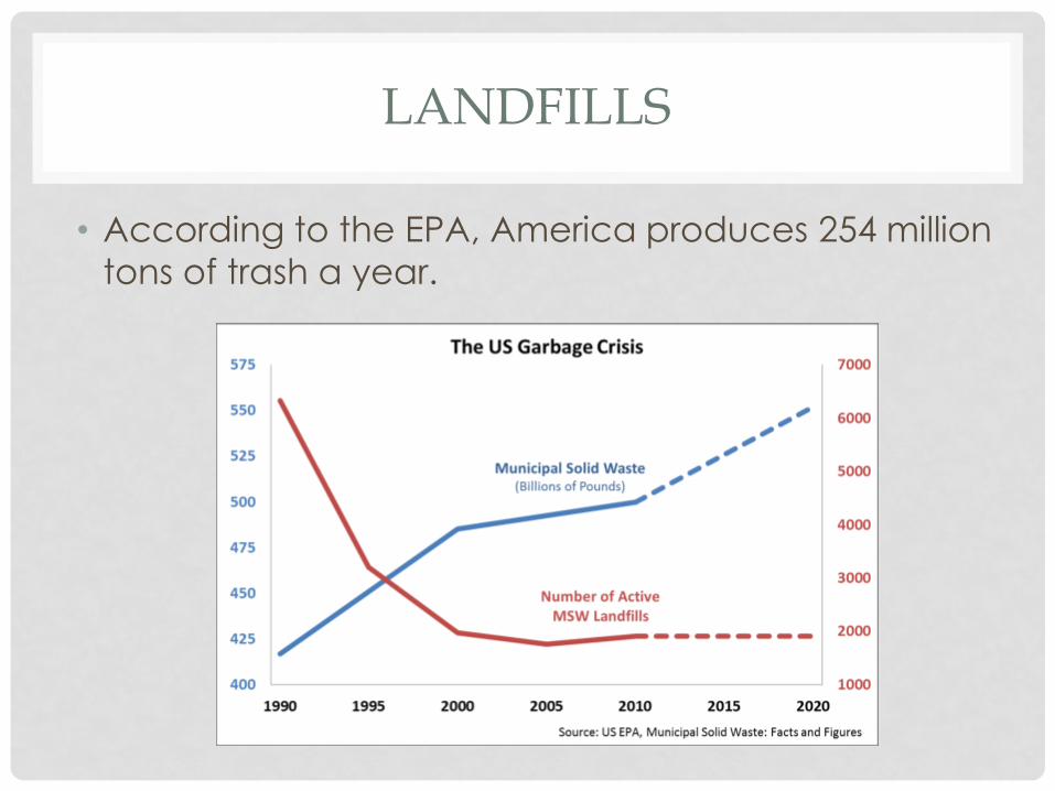
LANDFILLS
• According to the EPA, America produces 254 million
tons of trash a year.
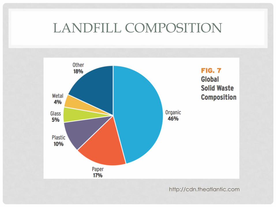
LANDFILL COMPOSITION
http://cdn.theatlantic.com
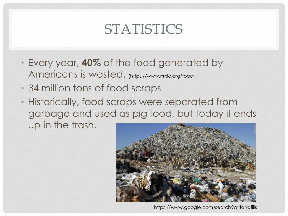
STATISTICS
• Every year, 40% of the food generated by
Americans is wasted. (https://www.nrdc.org/food)
• 34 million tons of food scraps
• Historically, food scraps were separated from
garbage and used as pig food, but today it ends
up in the trash.
https://www.google.com/search?q=landfills
SOLUTION
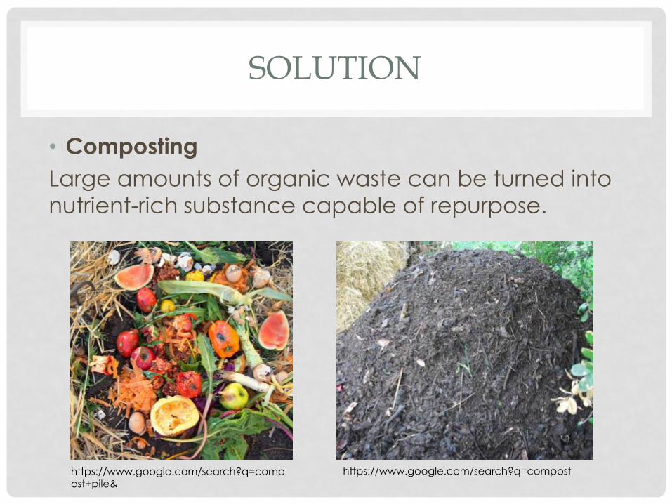
• Composting
Large amounts of organic waste can be turned into
nutrient-rich substance capable of repurpose.
https://www.google.com/search?q=compost+pile&
https://www.google.com/search?q=compost
COMPOSTING
• Typically the organic material is decomposed using
microorganisms
• However, there is a faster way-
Vermicomposting
BACKGROUND
• ver· mi· com· post· ing [ˌvərməˈkämpōstiNG] NOUN,
the use of earthworms to convert organic waste
into fertilizer.• Vermicomposting." Oxford University Press, n.d. Web. 6 Nov. 2015.
• Vermicomposting is an effective and beneficial
way to reduce the amount of trash that is being
dumped into landfills every day
OBJECTIVES
• Create a continuous, flow-through vermicast system
• Worm excretions are a useful form of topsoil and
fertilizer that can grow better food
• Design will be small enough for an “everyday”
person to use
SCOPE
• Design is expected to deliver food to flow through
system
• Best species of worm will be determined from
research
• Data on worm doubling time and food
consumption will be taken
TASKS
• Our main task will be the construction of the flow-
through bin
• Worms must consume a certain amount of food
before tests can be done on the flow-through bin
• A “food spraying” implement will be designed and
constructed as the food delivery system for the
worms
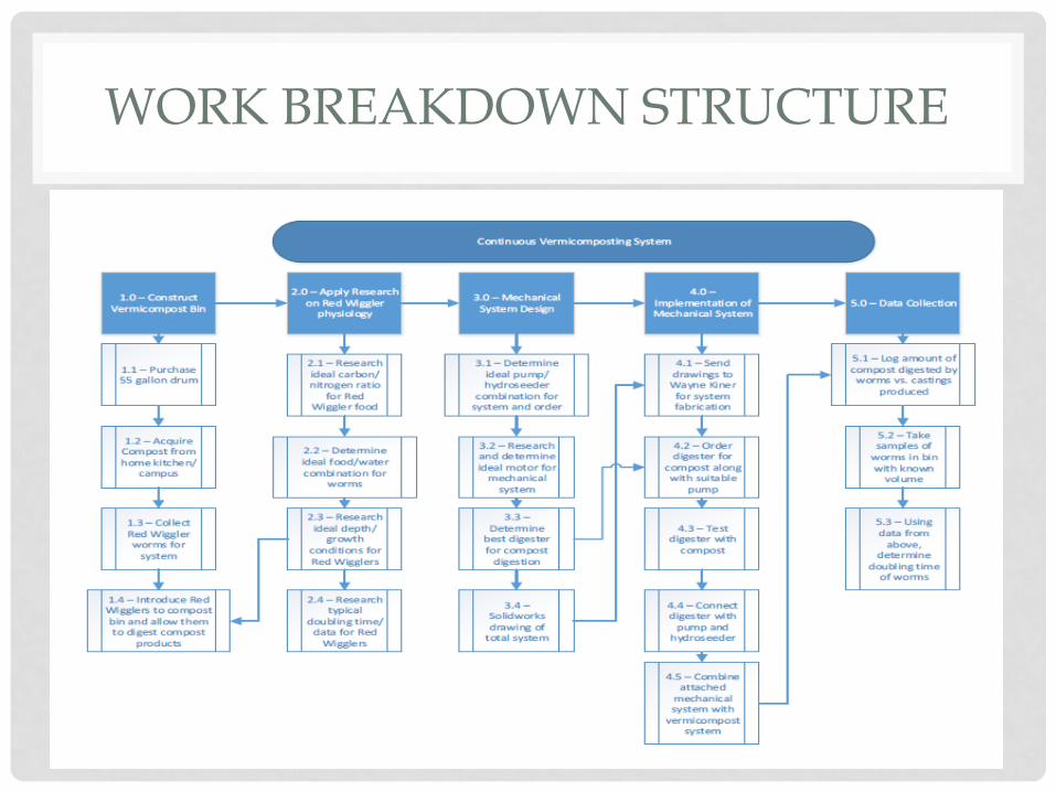
WORK BREAKDOWN STRUCTURE
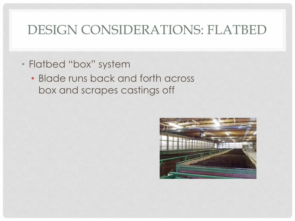
DESIGN CONSIDERATIONS: FLATBED
• Flatbed “box” system
• Blade runs back and forth across
box and scrapes castings off
FLATBED PROS
• Effective flow-through system
• Used by many large-scale industrial
vermicomposting systems
• Large surface area provides more room for worm
volume
FLATBED CONS
• Difficult to fit into small, domestic settings
• Laterally moving blades require more power
• More problematic to evenly distribute compost
• Larger amounts of water needed for more surface
area
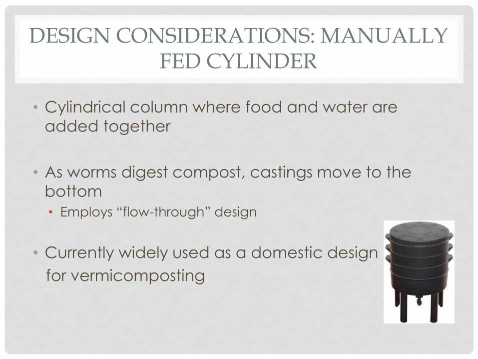
DESIGN CONSIDERATIONS: MANUALLY FED CYLINDER
• Cylindrical column where food and water are
added together
• As worms digest compost, castings move to the
bottom
• Employs “flow-through” design
• Currently widely used as a domestic design
for vermicomposting
MANUALLY FED CYLINDER PROS
• Good size for every-day households
• Flow-through system
• Easy to control parameters
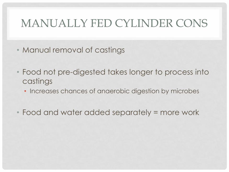
MANUALLY FED CYLINDER CONS
• Manual removal of castings
• Food not pre-digested takes longer to process into
castings
• Increases chances of anaerobic digestion by microbes
• Food and water added separately = more work
SECURITY
• Secure and private work and construction
environment
• Unaltered ambient conditions for worms to ensure
proper data collection
• Protection of public from potentially hazardous
parts
• Usage of non-invasive worm species
BAE 1012 CONTRIBUTIONS
• Research on species physiology and ideal
conditions for vermicomposting
• Research on mechanical specifications of
hydroseeder sprayers and ideal material
composition of semi-solid spraying
DELIVERY
• The final product must be a sustainable, continuous,
flow-through bin that digests and delivers food to
worms
• Research on why the specific worm species that
was chosen will also be presented
• Doubling time and food consumption will
demonstrate efficiency of system
WORM BIN DESIGN CONSIDERATIONS
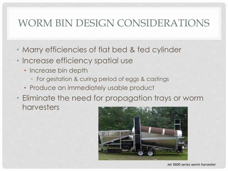
• Marry efficiencies of flat bed & fed cylinder
• Increase efficiency spatial use
• Increase bin depth
• For gestation & curing period of eggs & castings
• Produce an immediately usable product
• Eliminate the need for propagation trays or worm
harvesters
Jet 3600 series worm harvester
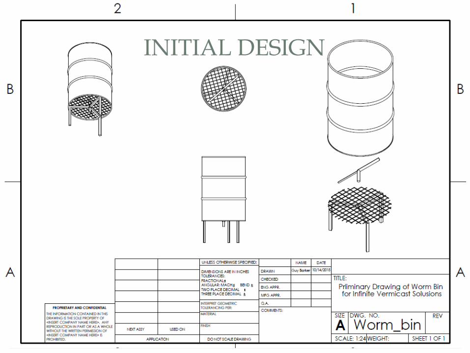
INITIAL DESIGN
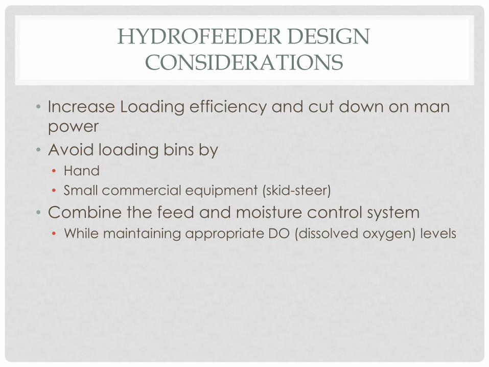
HYDROFEEDER DESIGN CONSIDERATIONS
• Increase Loading efficiency and cut down on man
power
• Avoid loading bins by
• Hand
• Small commercial equipment (skid-steer)
• Combine the feed and moisture control system
• While maintaining appropriate DO (dissolved oxygen) levels
INITIAL DESIGN OF HYDROFEEDER
VERMICULTURE
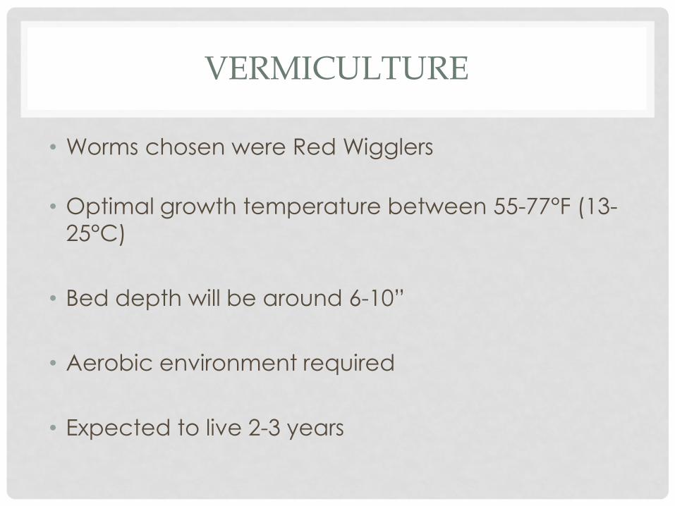
• Worms chosen were Red Wigglers
• Optimal growth temperature between 55-77°F (13-
25°C)
• Bed depth will be around 6-10”
• Aerobic environment required
• Expected to live 2-3 years
FOOD FOR VERMICULTURE
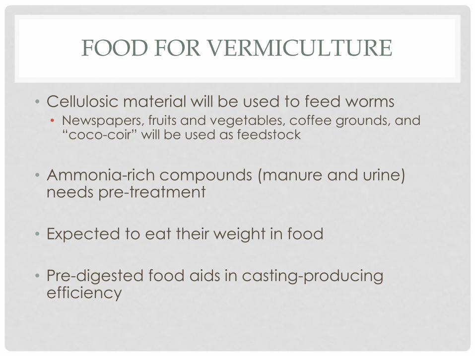
• Cellulosic material will be used to feed worms• Newspapers, fruits and vegetables, coffee grounds, and
“coco-coir” will be used as feedstock
• Ammonia-rich compounds (manure and urine) needs pre-treatment
• Expected to eat their weight in food
• Pre-digested food aids in casting-producing efficiency
DEALING WITH POPULATION GROWTH
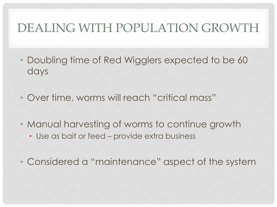
• Doubling time of Red Wigglers expected to be 60
days
• Over time, worms will reach “critical mass”
• Manual harvesting of worms to continue growth
• Use as bait or feed – provide extra business
• Considered a “maintenance” aspect of the system
COMPOST THAT CAN NOT BE USED
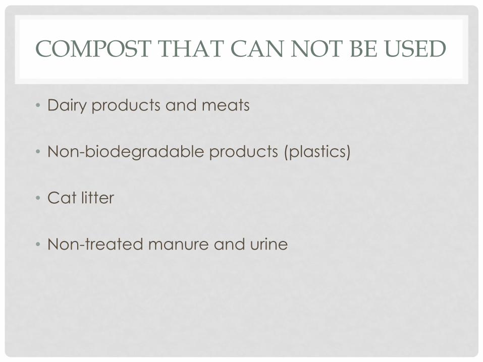
• Dairy products and meats
• Non-biodegradable products (plastics)
• Cat litter
• Non-treated manure and urine
PERFORMANCE
• Duties already performed:
• Research of vermiculture and worm physiology
• SolidWorks drawing of potential system design
• Duties to be carried out:
• Order parts and materials for bin construction
• System set-up and construction
• Fill bin/bed with compost and worms
• Test system with digester and food sprayer
• Collect necessary data
INFINITE VERMICAST SOLUTIONS Established 2015
Final Project Report – April 28th, 2016
Guy Barker Taylor Conley
Matthew Gallagher Magen Kegley
2 | I n f i n i t e V e r m i c a s t S o l u t i o n s
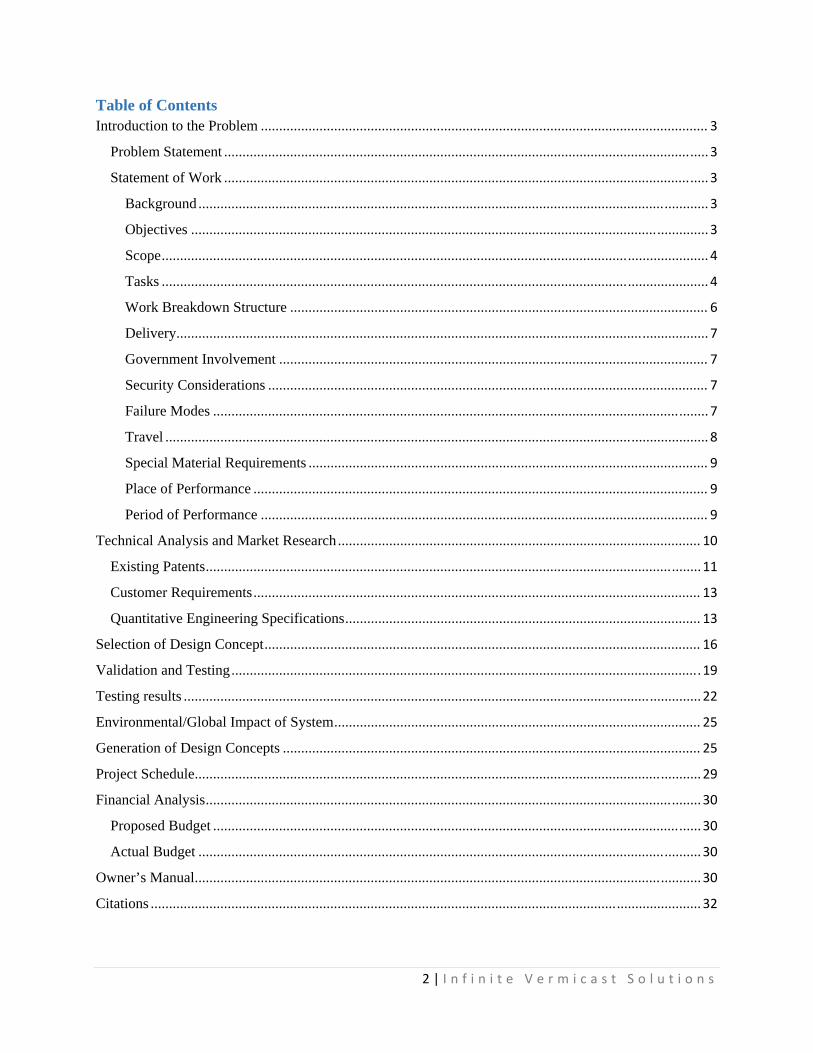
Table of Contents Introduction to the Problem .......................................................................................................................... 3
Problem Statement .................................................................................................................................... 3
Statement of Work .................................................................................................................................... 3
Background ........................................................................................................................................... 3
Objectives ............................................................................................................................................. 3
Scope ..................................................................................................................................................... 4
Tasks ..................................................................................................................................................... 4
Work Breakdown Structure .................................................................................................................. 6
Delivery................................................................................................................................................. 7
Government Involvement ..................................................................................................................... 7
Security Considerations ........................................................................................................................ 7
Failure Modes ....................................................................................................................................... 7
Travel .................................................................................................................................................... 8
Special Material Requirements ............................................................................................................. 9
Place of Performance ............................................................................................................................ 9
Period of Performance .......................................................................................................................... 9
Technical Analysis and Market Research ................................................................................................... 10
Existing Patents ....................................................................................................................................... 11
Customer Requirements .......................................................................................................................... 13
Quantitative Engineering Specifications ................................................................................................. 13
Selection of Design Concept ....................................................................................................................... 16
Validation and Testing ................................................................................................................................ 19
Testing results ............................................................................................................................................. 22
Environmental/Global Impact of System .................................................................................................... 25
Generation of Design Concepts .................................................................................................................. 25
Project Schedule .......................................................................................................................................... 29
Financial Analysis ....................................................................................................................................... 30
Proposed Budget ..................................................................................................................................... 30
Actual Budget ......................................................................................................................................... 30
Owner’s Manual .......................................................................................................................................... 30
Citations ...................................................................................................................................................... 32
3 | I n f i n i t e V e r m i c a s t S o l u t i o n s
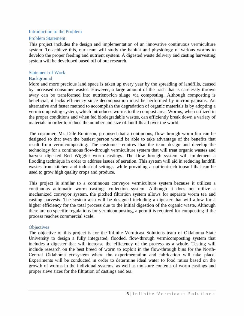
Introduction to the Problem
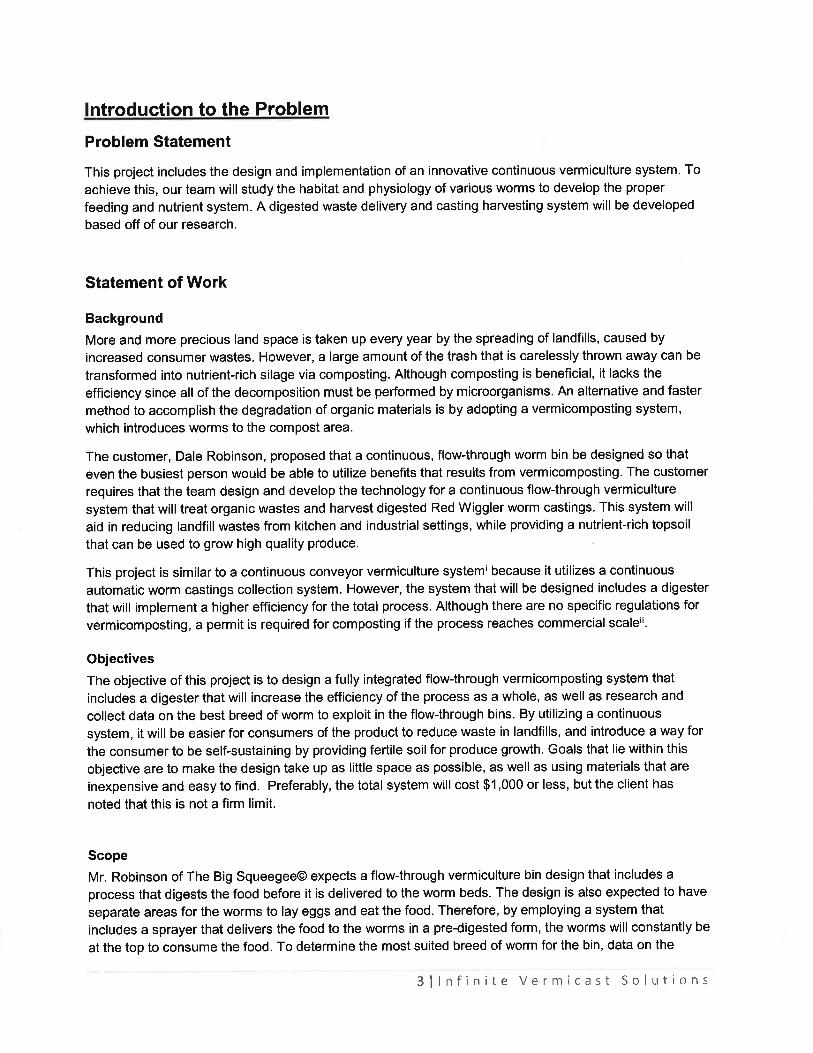
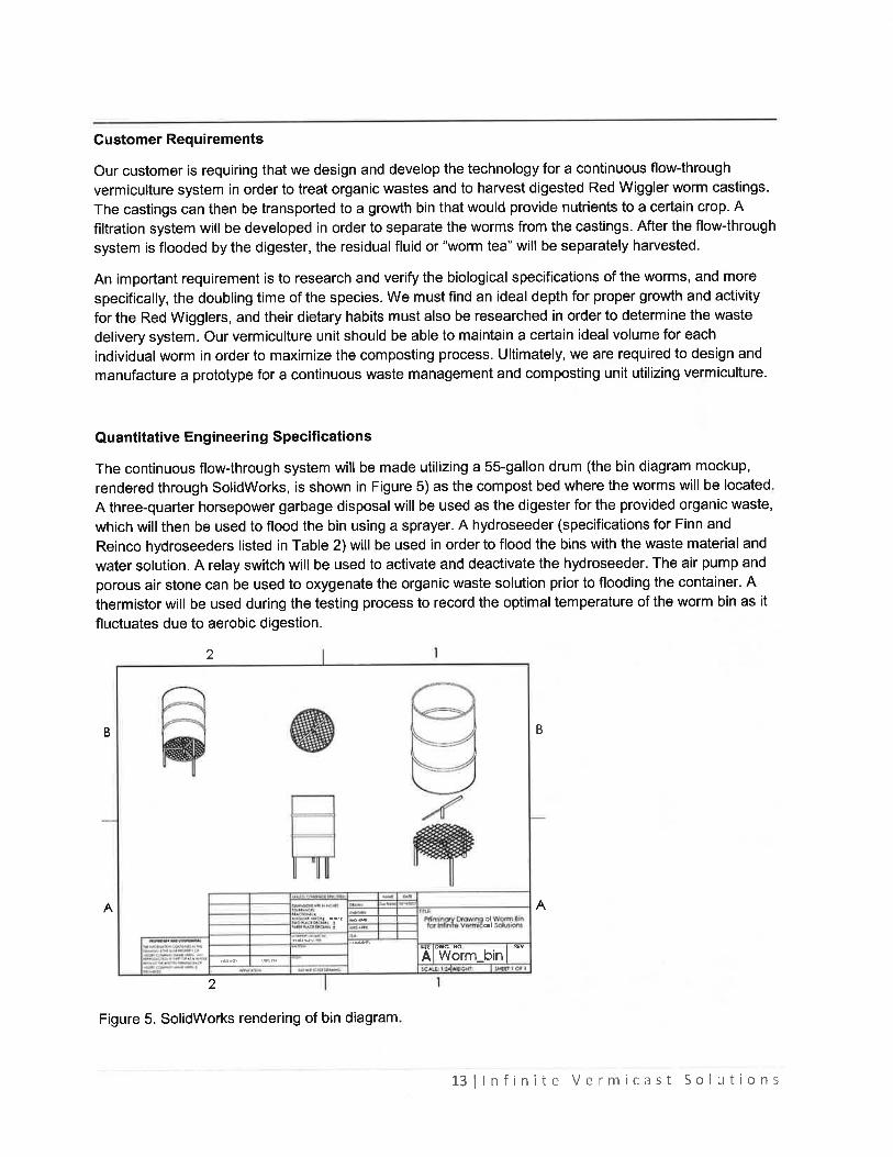
Problem Statement This project includes the design and implementation of an innovative continuous vermiculture system. To achieve this, our team will study the habitat and physiology of various worms to develop the proper feeding and nutrient system. A digested waste delivery and casting harvesting system will be developed based off of our research. Statement of Work Background More and more precious land space is taken up every year by the spreading of landfills, caused by increased consumer wastes. However, a large amount of the trash that is carelessly thrown away can be transformed into nutrient-rich silage via composting. Although composting is beneficial, it lacks efficiency since decomposition must be performed by microorganisms. An alternative and faster method to accomplish the degradation of organic materials is by adopting a vermicomposting system, which introduces worms to the compost area. Worms, when utilized in the proper conditions and when fed biodegradable wastes, can efficiently break down a variety of materials in order to reduce the number and size of landfills all over the world. The customer, Mr. Dale Robinson, proposed that a continuous, flow-through worm bin can be designed so that even the busiest person would be able to take advantage of the benefits that result from vermicomposting. The customer requires that the team design and develop the technology for a continuous flow-through vermiculture system that will treat organic wastes and harvest digested Red Wiggler worm castings. The flow-through system will implement a flooding technique in order to address issues of aeration. This system will aid in reducing landfill wastes from kitchen and industrial settings, while providing a nutrient-rich topsoil that can be used to grow high quality crops and produce. This project is similar to a continuous conveyor vermiculture system because it utilizes a continuous automatic worm castings collection system. Although it does not utilize a mechanized conveyor system, the pitched filtration system allows for separate worm tea and casting harvests. The system also will be designed including a digester that will allow for a higher efficiency for the total process due to the initial digestion of the organic waste. Although there are no specific regulations for vermicomposting, a permit is required for composting if the process reaches commercial scale. Objectives The objective of this project is for the Infinite Vermicast Solutions team of Oklahoma State University to design a fully integrated, flooded, flow-through vermicomposting system that includes a digester that will increase the efficiency of the process as a whole. Testing will include research on the best breed of worm to exploit in the flow-through bins for the North-Central Oklahoma ecosystem where the experimentation and fabrication will take place. Experiments will be conducted in order to determine ideal water to food ratios based on the growth of worms in the individual systems, as well as moisture contents of worm castings and proper sieve sizes for the filtration of castings and tea.
4 | I n f i n i t e V e r m i c a s t S o l u t i o n s
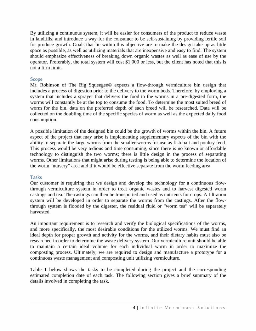
By utilizing a continuous system, it will be easier for consumers of the product to reduce waste in landfills, and introduce a way for the consumer to be self-sustaining by providing fertile soil for produce growth. Goals that lie within this objective are to make the design take up as little space as possible, as well as utilizing materials that are inexpensive and easy to find. The system should emphasize effectiveness of breaking down organic wastes as well as ease of use by the operator. Preferably, the total system will cost $1,000 or less, but the client has noted that this is not a firm limit. Scope Mr. Robinson of The Big Squeegee© expects a flow-through vermiculture bin design that includes a process of digestion prior to the delivery to the worm beds. Therefore, by employing a system that includes a sprayer that delivers the food to the worms in a pre-digested form, the worms will constantly be at the top to consume the food. To determine the most suited breed of worm for the bin, data on the preferred depth of each breed will be researched. Data will be collected on the doubling time of the specific species of worm as well as the expected daily food consumption. A possible limitation of the designed bin could be the growth of worms within the bin. A future aspect of the project that may arise is implementing supplementary aspects of the bin with the ability to separate the large worms from the smaller worms for use as fish bait and poultry feed. This process would be very tedious and time consuming, since there is no known or affordable technology to distinguish the two worms; there is little design in the process of separating worms. Other limitations that might arise during testing is being able to determine the location of the worm “nursery” area and if it would be effective separate from the worm feeding area. Tasks Our customer is requiring that we design and develop the technology for a continuous flow-through vermiculture system in order to treat organic wastes and to harvest digested worm castings and tea. The castings can then be transported and used as nutrients for crops. A filtration system will be developed in order to separate the worms from the castings. After the flow-through system is flooded by the digester, the residual fluid or “worm tea” will be separately harvested. An important requirement is to research and verify the biological specifications of the worms, and more specifically, the most desirable conditions for the utilized worms. We must find an ideal depth for proper growth and activity for the worms, and their dietary habits must also be researched in order to determine the waste delivery system. Our vermiculture unit should be able to maintain a certain ideal volume for each individual worm in order to maximize the composting process. Ultimately, we are required to design and manufacture a prototype for a continuous waste management and composting unit utilizing vermiculture. Table 1 below shows the tasks to be completed during the project and the corresponding estimated completion date of each task. The following section gives a brief summary of the details involved in completing the task.
5 | I n f i n i t e V e r m i c a s t S o l u t i o n s
Table 1. Task List and Completion Dates
Task Number
Work Milestones Projected Completion Date
Task 1 Review Customer Order 10/14/15
Task 2 Preliminary Design Modeling 10/27/15
Task 3 Preliminary Design Report Draft 11/13/15
Task 4 Preliminary Design Final Report 11/23/15
Task 5 Preliminary Design Presentation with Client
12/3/15
Task 6 Experimentation and Testing Begins 2/1/16
Task 7 Experimentation and Testing Ends 3/20/16
Task 8 Manufactured Prototype 4/1/16
Task 9 Prototype Testing 4/21/01
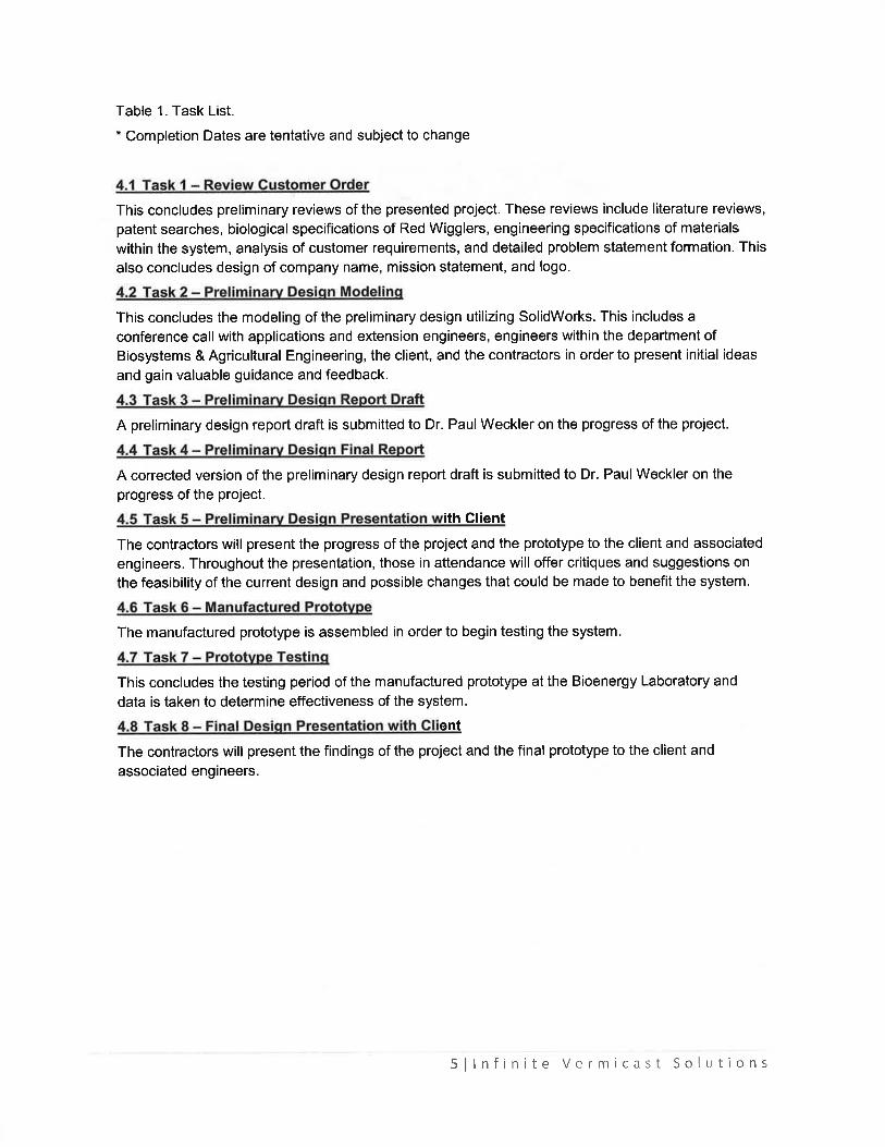
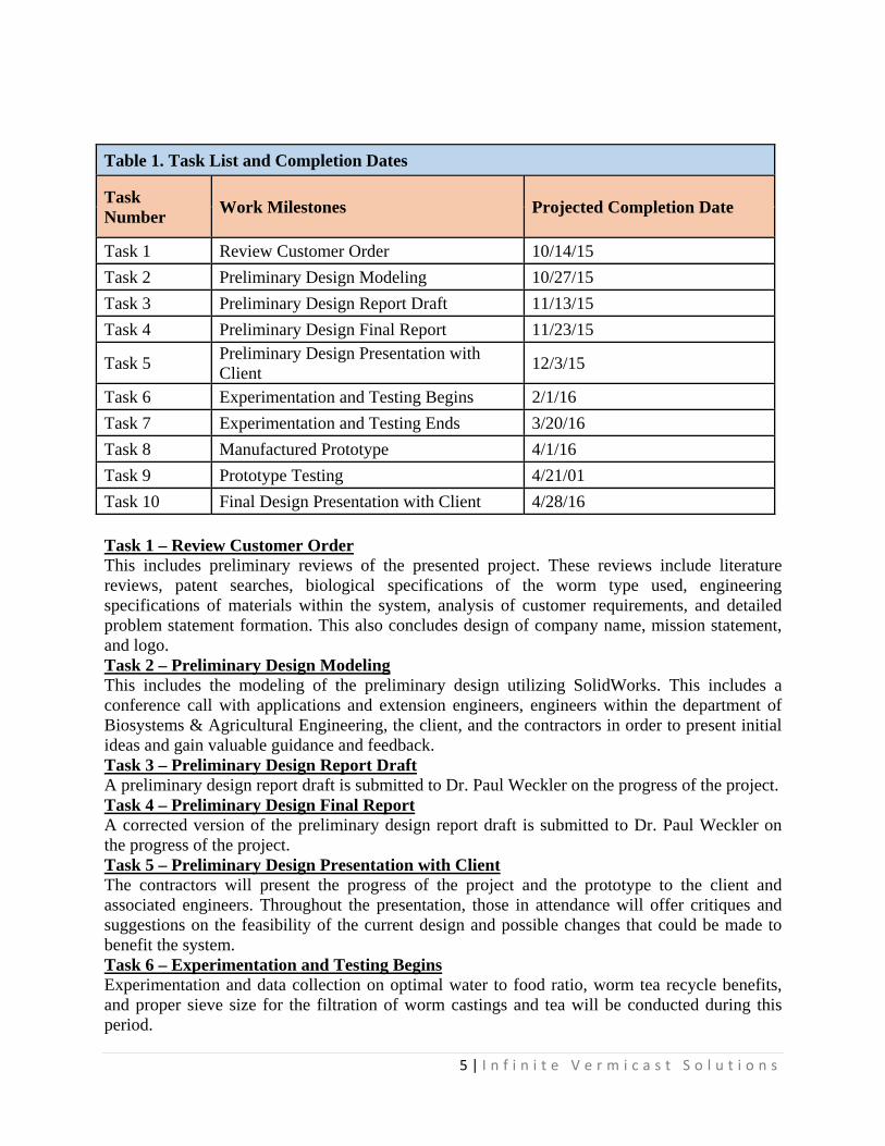
Task 10 Final Design Presentation with Client 4/28/16 Task 1 – Review Customer Order This includes preliminary reviews of the presented project. These reviews include literature reviews, patent searches, biological specifications of the worm type used, engineering specifications of materials within the system, analysis of customer requirements, and detailed problem statement formation. This also concludes design of company name, mission statement, and logo. Task 2 – Preliminary Design Modeling This includes the modeling of the preliminary design utilizing SolidWorks. This includes a conference call with applications and extension engineers, engineers within the department of Biosystems & Agricultural Engineering, the client, and the contractors in order to present initial ideas and gain valuable guidance and feedback. Task 3 – Preliminary Design Report Draft A preliminary design report draft is submitted to Dr. Paul Weckler on the progress of the project. Task 4 – Preliminary Design Final Report A corrected version of the preliminary design report draft is submitted to Dr. Paul Weckler on the progress of the project. Task 5 – Preliminary Design Presentation with Client The contractors will present the progress of the project and the prototype to the client and associated engineers. Throughout the presentation, those in attendance will offer critiques and suggestions on the feasibility of the current design and possible changes that could be made to benefit the system. Task 6 – Experimentation and Testing Begins Experimentation and data collection on optimal water to food ratio, worm tea recycle benefits, and proper sieve size for the filtration of worm castings and tea will be conducted during this period.
6 | I n f i n i t e V e r m i c a s t S o l u t i o n s
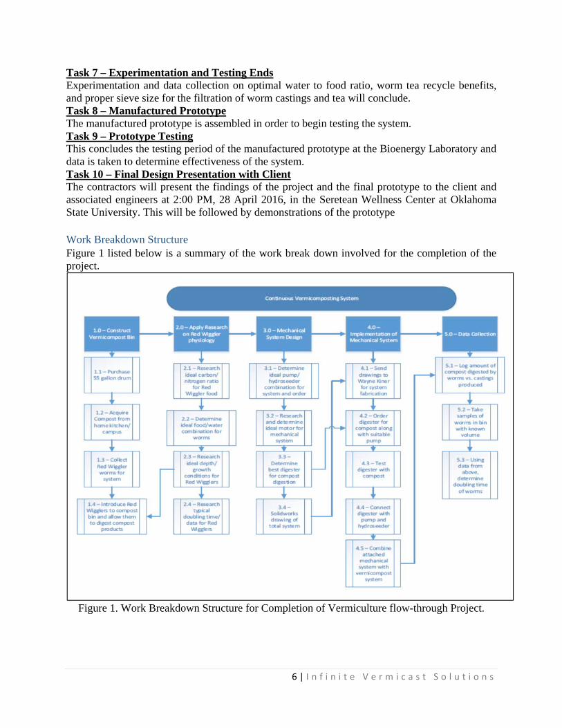
Task 7 – Experimentation and Testing Ends Experimentation and data collection on optimal water to food ratio, worm tea recycle benefits, and proper sieve size for the filtration of worm castings and tea will conclude. Task 8 – Manufactured Prototype The manufactured prototype is assembled in order to begin testing the system. Task 9 – Prototype Testing This concludes the testing period of the manufactured prototype at the Bioenergy Laboratory and data is taken to determine effectiveness of the system. Task 10 – Final Design Presentation with Client The contractors will present the findings of the project and the final prototype to the client and associated engineers at 2:00 PM, 28 April 2016, in the Seretean Wellness Center at Oklahoma State University. This will be followed by demonstrations of the prototype Work Breakdown Structure Figure 1 listed below is a summary of the work break down involved for the completion of the project.
Figure 1. Work Breakdown Structure for Completion of Vermiculture flow-through Project.
7 | I n f i n i t e V e r m i c a s t S o l u t i o n s
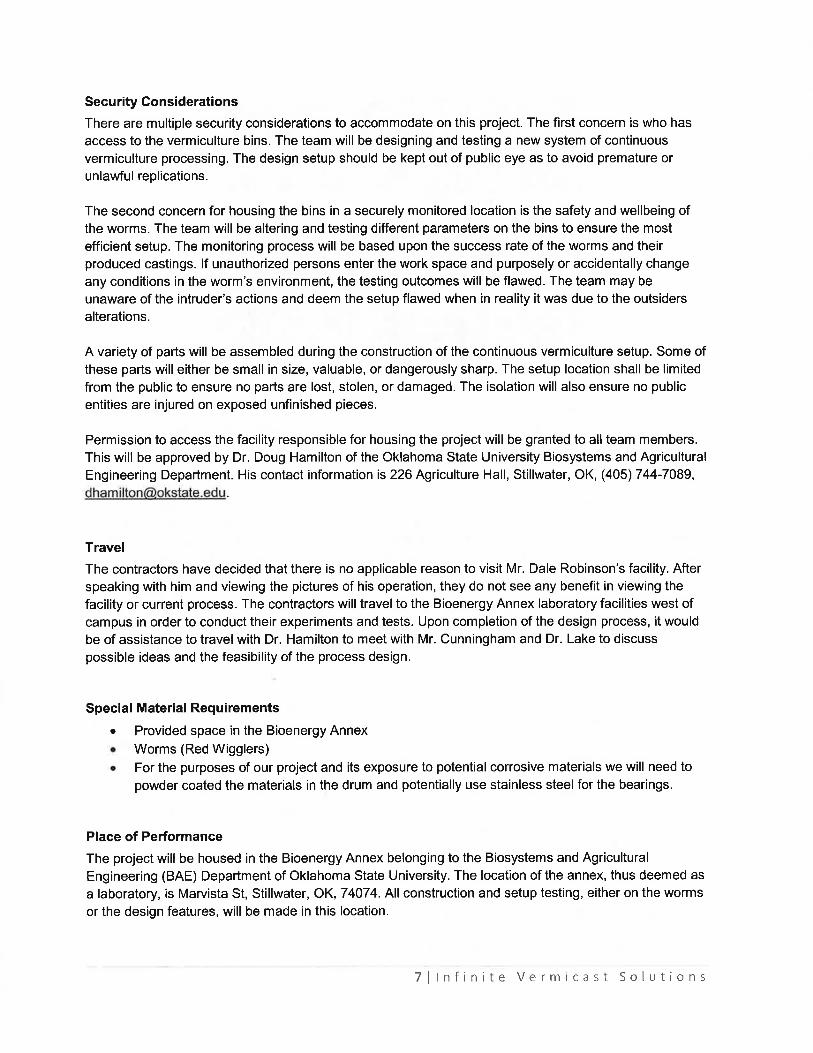
Delivery We are to deliver a continuous worm bin with an automated feed delivery system. The designs will be delivered via a presentation in Ag Hall, 3 December 2015 at 1:45 PM; location will be Agricultural Hall 210, Stillwater, Oklahoma. Prototypes of both the bin design and hydrofeeder system will be delivered and demonstrated 28 April 2016 at 2:00 PM at the Seretean Wellness Center at Oklahoma State University, Stillwater, Oklahoma. No governmental documentation of receipt is necessary. Government Involvement Furnished Property, Material, Equipment, or Information (GFP, GFM, GFE, or GFI): Since this project is being designed and constructed on land grant university property, the area where it will be built belongs to the government. The specific location of the worm-bin will be at the Oklahoma State University Bioenergy Annex off of Marvista St. in Stillwater, OK. Material will be purchased by the contractor using Mr. Robinson’s provided budget of $1,000. Security Considerations There are multiple security considerations to accommodate on this project. The first concern is who has access to the vermiculture bins. The team will be designing and testing a new system of continuous vermiculture processing. The design setup should be kept out of public eye as to avoid premature or unlawful replications. The second concern for housing the bins in a securely monitored location is the safety and well-being of the worms. The team will be altering and testing different parameters on the bins to ensure the most efficient setup. The monitoring process will be based upon the success rate of the worms and their produced castings. If unauthorized persons enter the work space and purposely or accidentally change any conditions in the worm’s environment, the testing outcomes will be flawed. The team may be unaware of the intruder’s actions and deem the setup flawed when in reality it was due to the outsider’s alterations. A variety of parts will be assembled during the construction of the continuous vermiculture setup. Some of these parts will either be small in size, valuable, or dangerously sharp. The setup location shall be limited from the public to ensure no parts are lost, stolen, or damaged. The isolation will also ensure no public entities are injured on exposed unfinished pieces. Permission to access the facility responsible for housing the project will be granted to all team members. This will be approved by Dr. Doug Hamilton of the Oklahoma State University Biosystems and Agricultural Engineering Department. His contact information is 226 Agriculture Hall, Stillwater, OK, (405) 744-7089, [email protected]. Failure Modes As with any project, there is a certain risk associated with the failure of the system. Some of these failures may be minor and only need a small part replacement, while other failures may be of monumental significance that could lead to human injury or even death. It is of extreme importance to know the failures associated with any project. It is a good idea to list the failures
8 | I n f i n i t e V e r m i c a s t S o l u t i o n s
along a gradient scale that lets you know how important the failure is to the system. The minor failures associated with this project are the paint types used on the system. The paint is in place to ensure that the worm substances do not rust or corrode the bin. The paint should be strong enough to resist corrosion and scraps. However, if the paint were to peal or get scraped, the structural integrity of the system would still hold true. If no paint were on the bin, if could possibly be years before any permanent damage was caused to the bin. The next failure to consider is the motor size of the garbage disposal used. This failure is of significant importance. The garbage disposal is responsible for preparing the food to be added to the worm bed. If the motor is not large enough to handle and shred the amount of food being added to the system, then no food will make it to the bin. If the disposal breaks, one would have the tear the food up by hand which would use a lot of man power and hours. If whole food is added to the bin, you risk the food heating up and going into anaerobic conditions. The heat involved in this process will kill your worms. If your garbage disposal cannot handle the food load, you risk ruining the workings of the entire system. A failure of medium significance is the workings of the hydrofeeder. The hydrofeeder is responsible for transporting the food and water from the digester to the worm bin. If the hydrofeeder fails and stops working, this does not affect the integrity to the workings of the system. If the hydrofeeder stops working, the food and water could be ladled out of the digester and manually added to the worm bin. The process would be inconvenient, but you would not need to stop the decomposition of the worm beds in order to fix the problem. The next failure to consider is the size of the screens used and the strength of the screen used. These parameters are also of great importance. If the screen cannot support the load of the castings, you risk having your screen tear. If the screen tears, the castings, food, and worms will fall through the system onto the floor. This may not be a mechanical failure, but a tear in the screen would deem the system useless. The same goes true for the size of the screen. If the size of the screen is too large, it would act the same as if there were a tear in the screen. However, the failure significance can be downgraded if the size if the screen were too small. If the screen size were too small, the castings would not be able to flow through the system. In this case, the system would no longer be a continuous vermiculture system. However, the system would not be deemed totally useless. You could use the bin as a batch process until plans were made to increase the size of the screen. Other failures to be considered are operation failures. It needs to be made clear to the operator that only foods that the worms can eat should be added to the system. Also, the water content of the soil needs to be maintained to ensure the survival of the worms in the system. If the worms die, then the system has failed. Travel A preliminary visit was made in October 2015 to Mr. Dale Robinson’s facility based out of Lawton, Oklahoma. After speaking with Mr. Robinson and touring his facility, no additional visits were required. The contractors will travel to the Bioenergy Annex laboratory facilities west of the Oklahoma State University campus in order to conduct their experiments and tests.
9 | I n f i n i t e V e r m i c a s t S o l u t i o n s
Special Material Requirements
Provided space in the Bioenergy Annex Worms (Red Wigglers) provided by Dr. Doug Hamilton
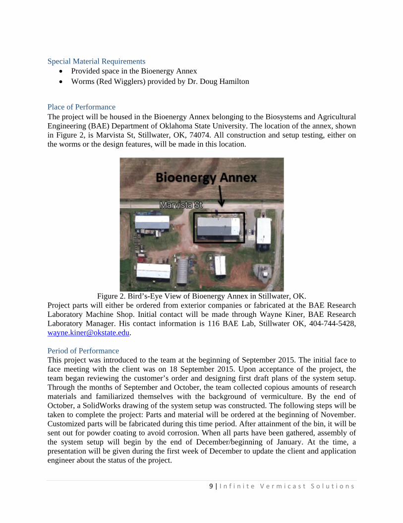
Place of Performance The project will be housed in the Bioenergy Annex belonging to the Biosystems and Agricultural Engineering (BAE) Department of Oklahoma State University. The location of the annex, shown in Figure 2, is Marvista St, Stillwater, OK, 74074. All construction and setup testing, either on the worms or the design features, will be made in this location.
Figure 2. Bird’s-Eye View of Bioenergy Annex in Stillwater, OK.
Project parts will either be ordered from exterior companies or fabricated at the BAE Research Laboratory Machine Shop. Initial contact will be made through Wayne Kiner, BAE Research Laboratory Manager. His contact information is 116 BAE Lab, Stillwater OK, 404-744-5428, [email protected]. Period of Performance This project was introduced to the team at the beginning of September 2015. The initial face to face meeting with the client was on 18 September 2015. Upon acceptance of the project, the team began reviewing the customer’s order and designing first draft plans of the system setup. Through the months of September and October, the team collected copious amounts of research materials and familiarized themselves with the background of vermiculture. By the end of October, a SolidWorks drawing of the system setup was constructed. The following steps will be taken to complete the project: Parts and material will be ordered at the beginning of November. Customized parts will be fabricated during this time period. After attainment of the bin, it will be sent out for powder coating to avoid corrosion. When all parts have been gathered, assembly of the system setup will begin by the end of December/beginning of January. At the time, a presentation will be given during the first week of December to update the client and application engineer about the status of the project.
10 | I n f i n i t e V e r m i c a s t S o l u t i o n s
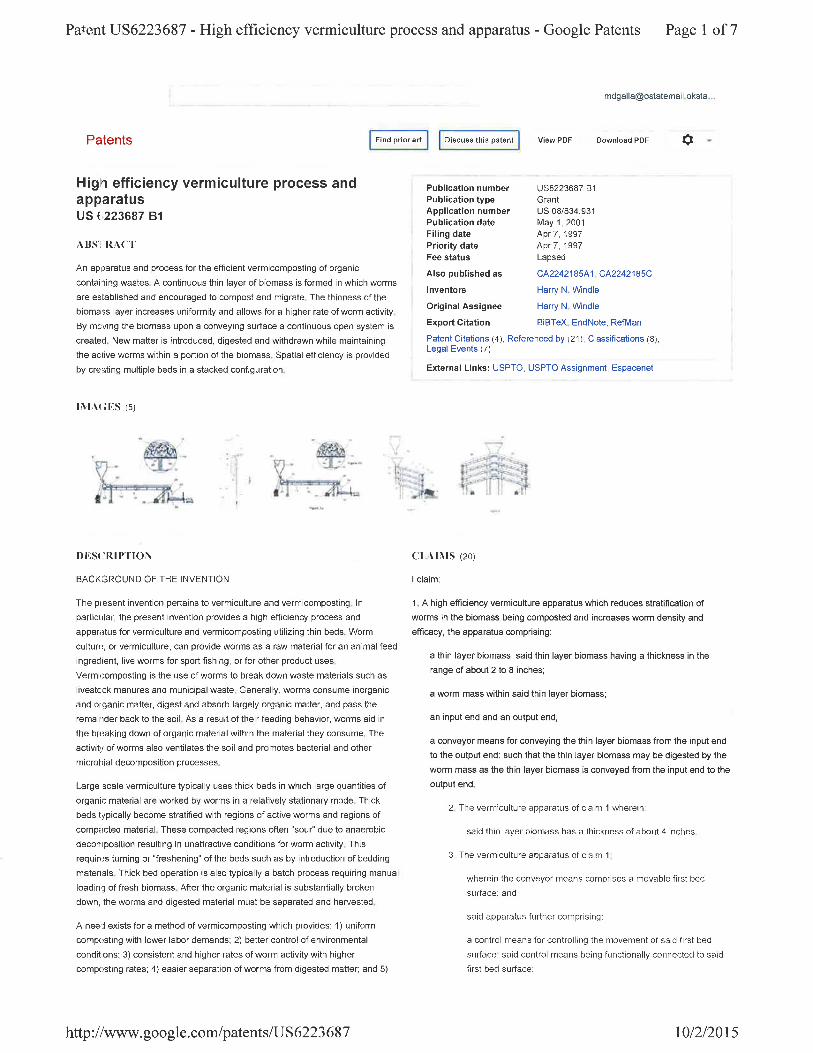
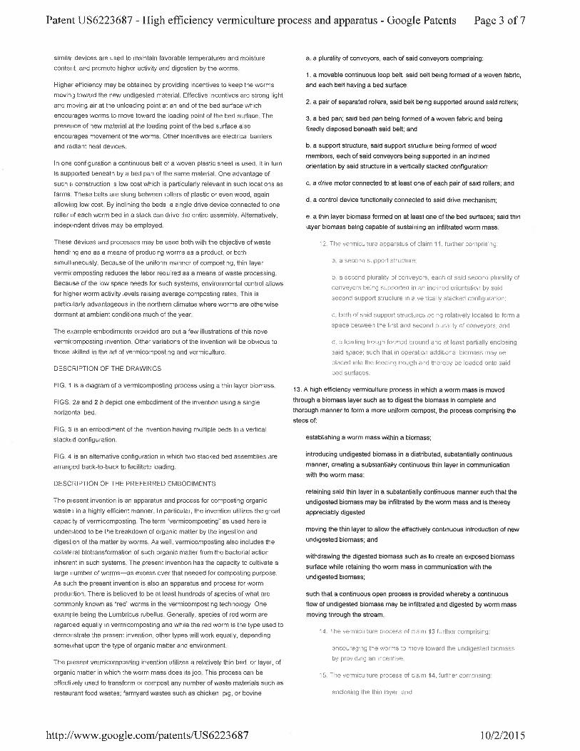
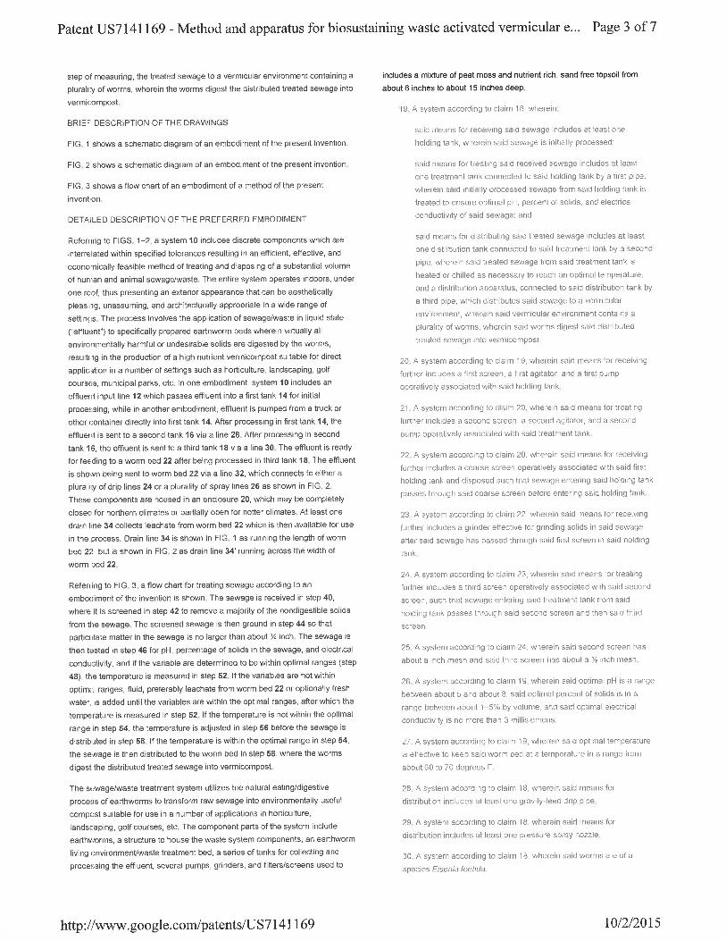
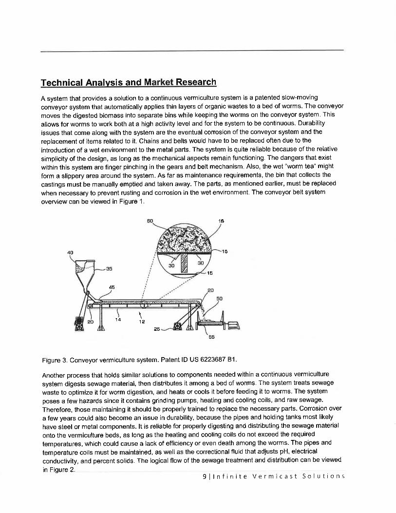
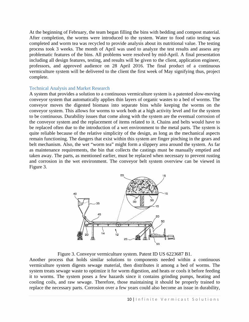
At the beginning of February, the team began filling the bins with bedding and compost material. After completion, the worms were introduced to the system. Water to food ratio testing was completed and worm tea was recycled to provide analysis about its nutritional value. The testing process took 3 weeks. The month of April was used to analyze the test results and assess any problematic features of the bins. All problems were resolved by mid-April. A final presentation including all design features, testing, and results will be given to the client, application engineer, professors, and approved audience on 28 April 2016. The final product of a continuous vermiculture system will be delivered to the client the first week of May signifying thus, project complete. Technical Analysis and Market Research A system that provides a solution to a continuous vermiculture system is a patented slow-moving conveyor system that automatically applies thin layers of organic wastes to a bed of worms. The conveyor moves the digested biomass into separate bins while keeping the worms on the conveyor system. This allows for worms to work both at a high activity level and for the system to be continuous. Durability issues that come along with the system are the eventual corrosion of the conveyor system and the replacement of items related to it. Chains and belts would have to be replaced often due to the introduction of a wet environment to the metal parts. The system is quite reliable because of the relative simplicity of the design, as long as the mechanical aspects remain functioning. The dangers that exist within this system are finger pinching in the gears and belt mechanism. Also, the wet “worm tea” might form a slippery area around the system. As far as maintenance requirements, the bin that collects the castings must be manually emptied and taken away. The parts, as mentioned earlier, must be replaced when necessary to prevent rusting and corrosion in the wet environment. The conveyor belt system overview can be viewed in Figure 3.
Figure 3. Conveyor vermiculture system. Patent ID US 6223687 B1.
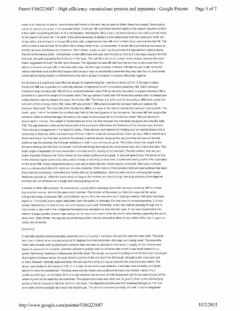
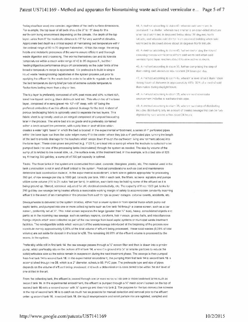
Another process that holds similar solutions to components needed within a continuous vermiculture system digests sewage material, then distributes it among a bed of worms. The system treats sewage waste to optimize it for worm digestion, and heats or cools it before feeding it to worms. The system poses a few hazards since it contains grinding pumps, heating and cooling coils, and raw sewage. Therefore, those maintaining it should be properly trained to replace the necessary parts. Corrosion over a few years could also become an issue in durability,
11 | I n f i n i t e V e r m i c a s t S o l u t i o n s
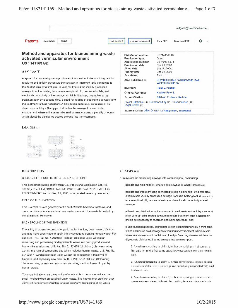
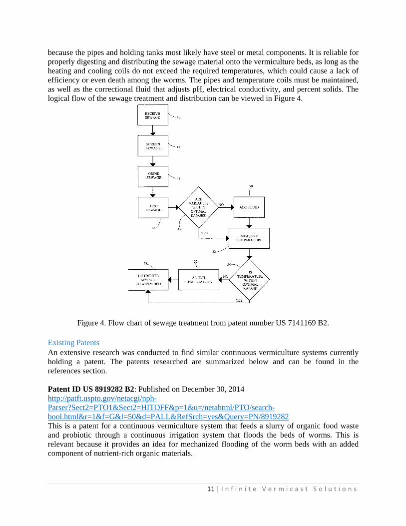
because the pipes and holding tanks most likely have steel or metal components. It is reliable for properly digesting and distributing the sewage material onto the vermiculture beds, as long as the heating and cooling coils do not exceed the required temperatures, which could cause a lack of efficiency or even death among the worms. The pipes and temperature coils must be maintained, as well as the correctional fluid that adjusts pH, electrical conductivity, and percent solids. The logical flow of the sewage treatment and distribution can be viewed in Figure 4.
Figure 4. Flow chart of sewage treatment from patent number US 7141169 B2.
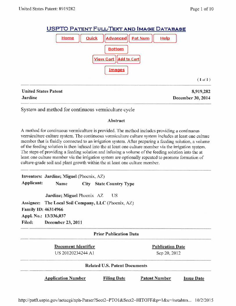
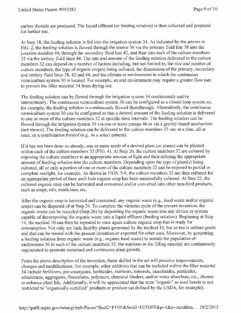
Existing Patents An extensive research was conducted to find similar continuous vermiculture systems currently holding a patent. The patents researched are summarized below and can be found in the references section. Patent ID US 8919282 B2: Published on December 30, 2014 http://patft.uspto.gov/netacgi/nph-Parser?Sect2=PTO1&Sect2=HITOFF&p=1&u=/netahtml/PTO/search-bool.html&r=1&f=G&l=50&d=PALL&RefSrch=yes&Query=PN/8919282 This is a patent for a continuous vermiculture system that feeds a slurry of organic food waste and probiotic through a continuous irrigation system that floods the beds of worms. This is relevant because it provides an idea for mechanized flooding of the worm beds with an added component of nutrient-rich organic materials.
12 | I n f i n i t e V e r m i c a s t S o l u t i o n s
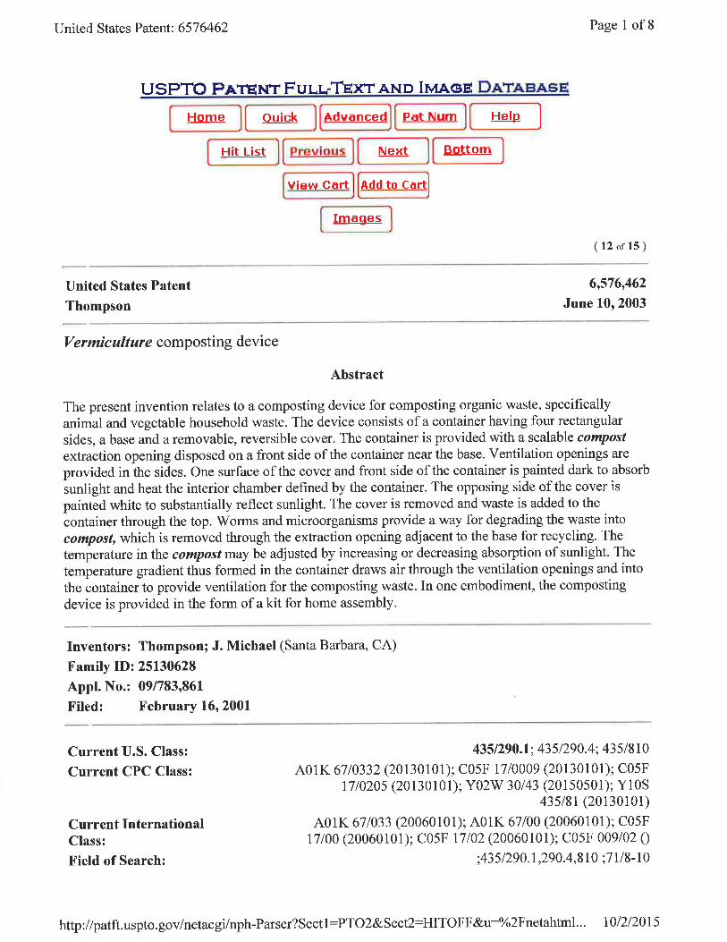
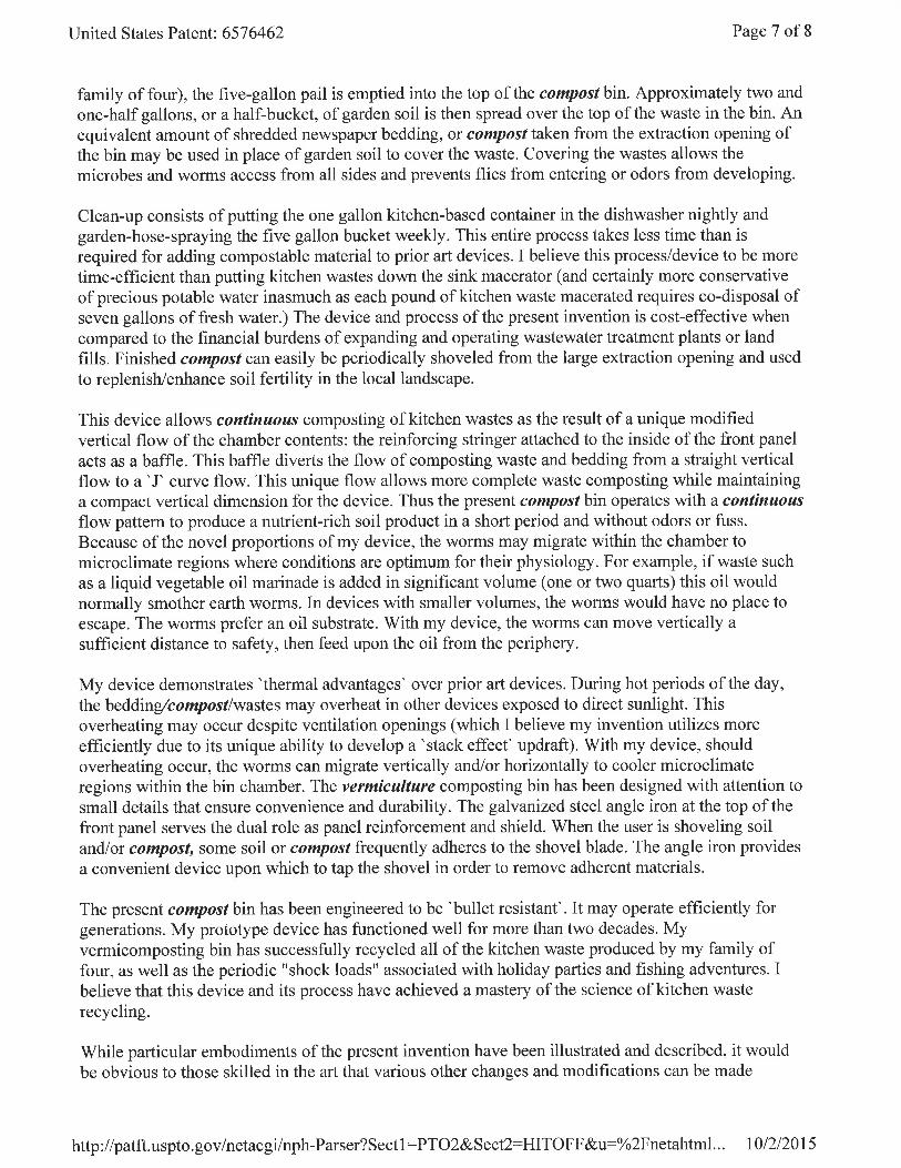
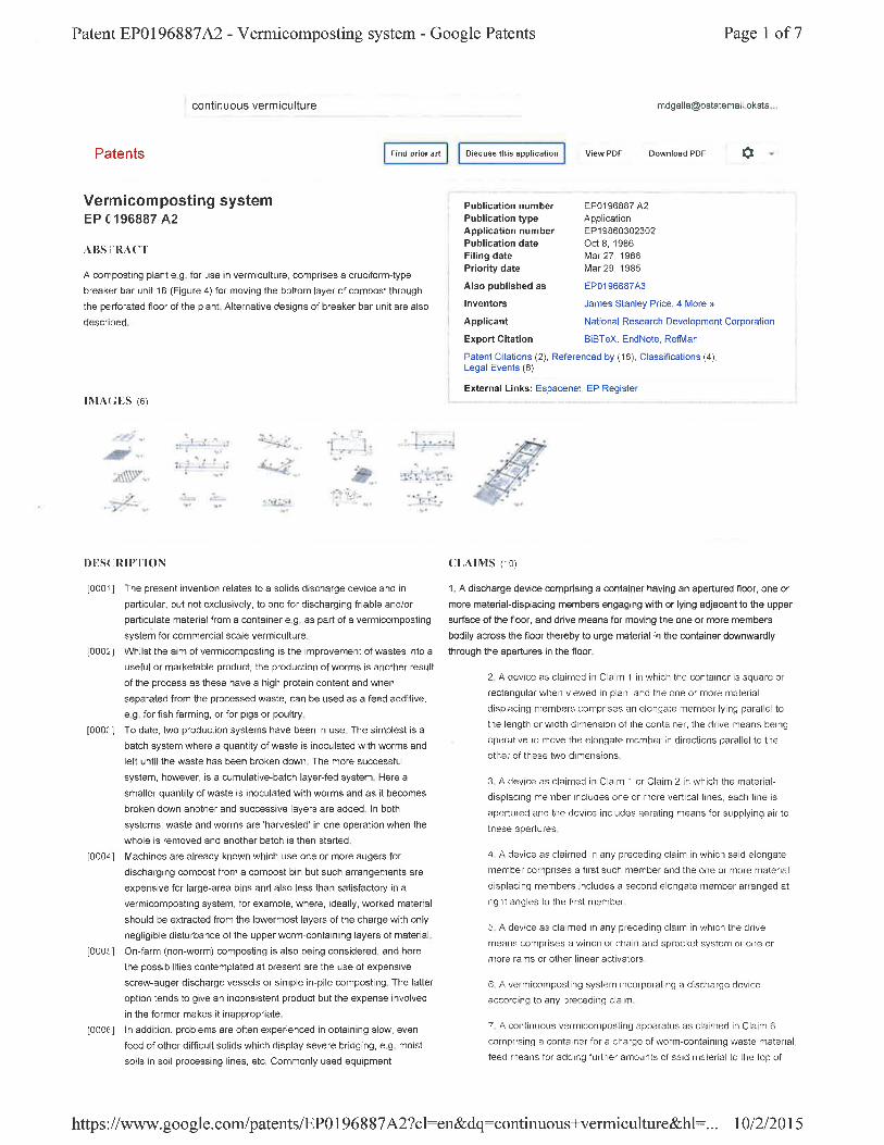
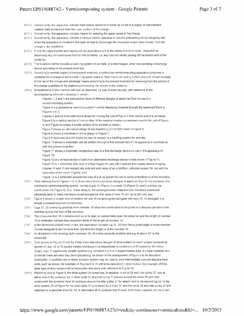
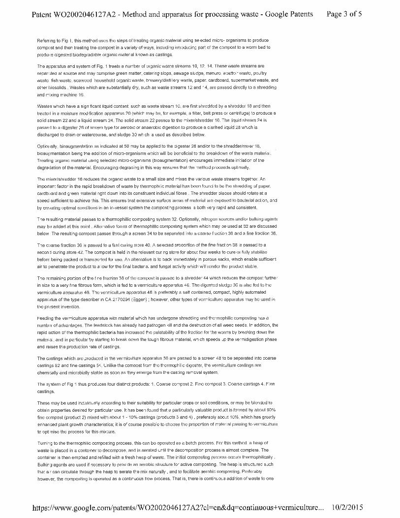
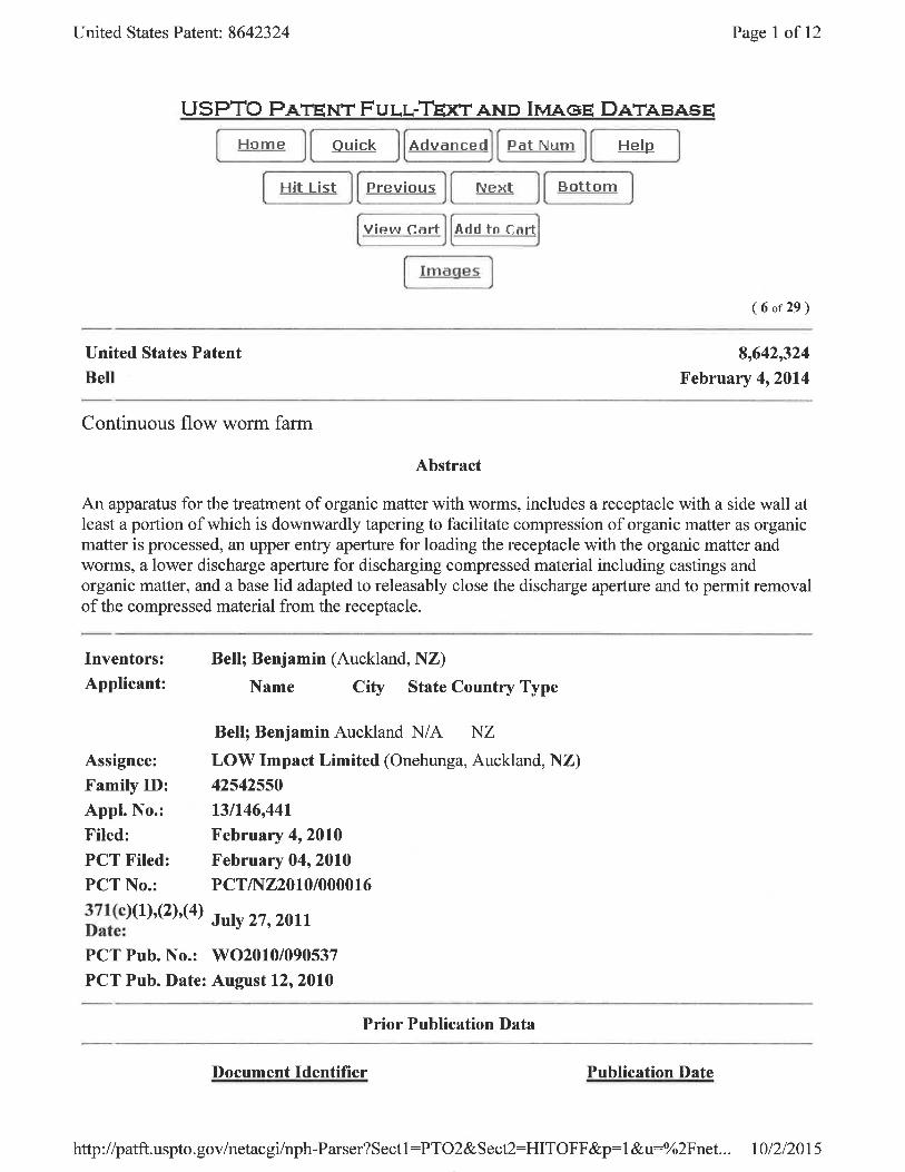
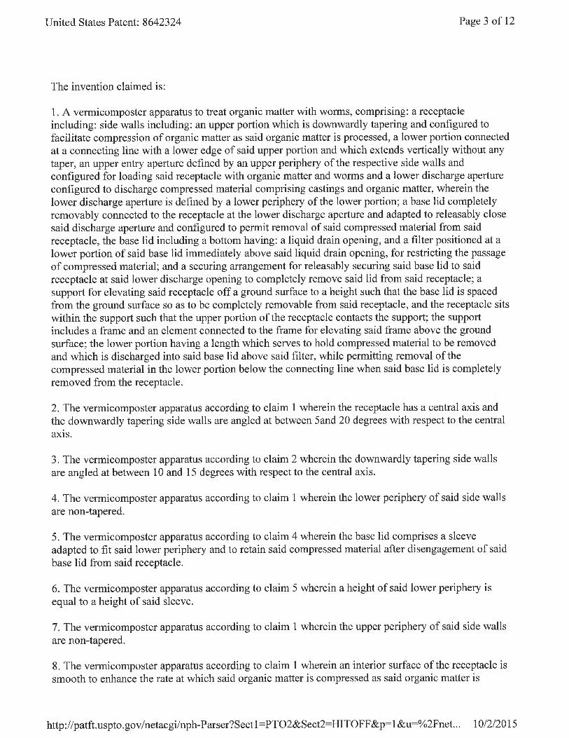
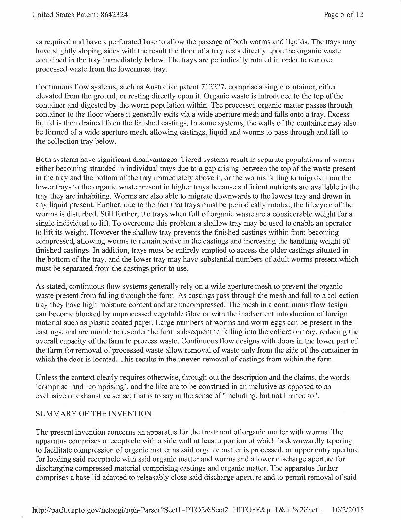
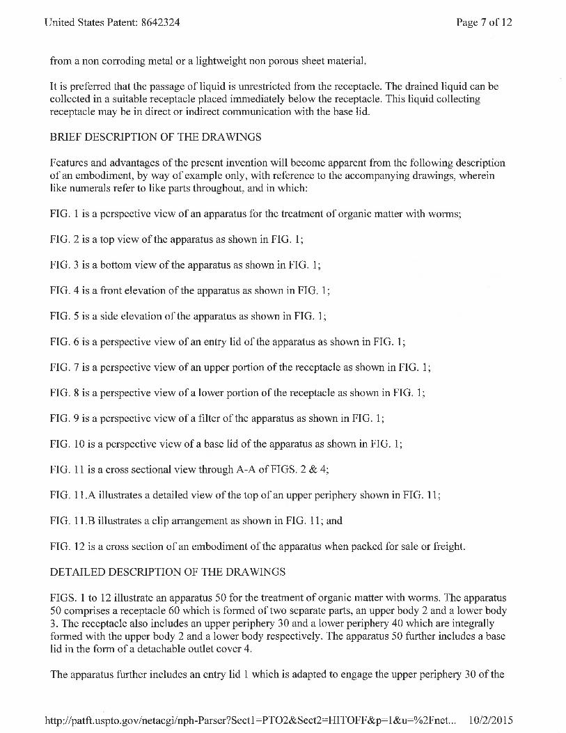
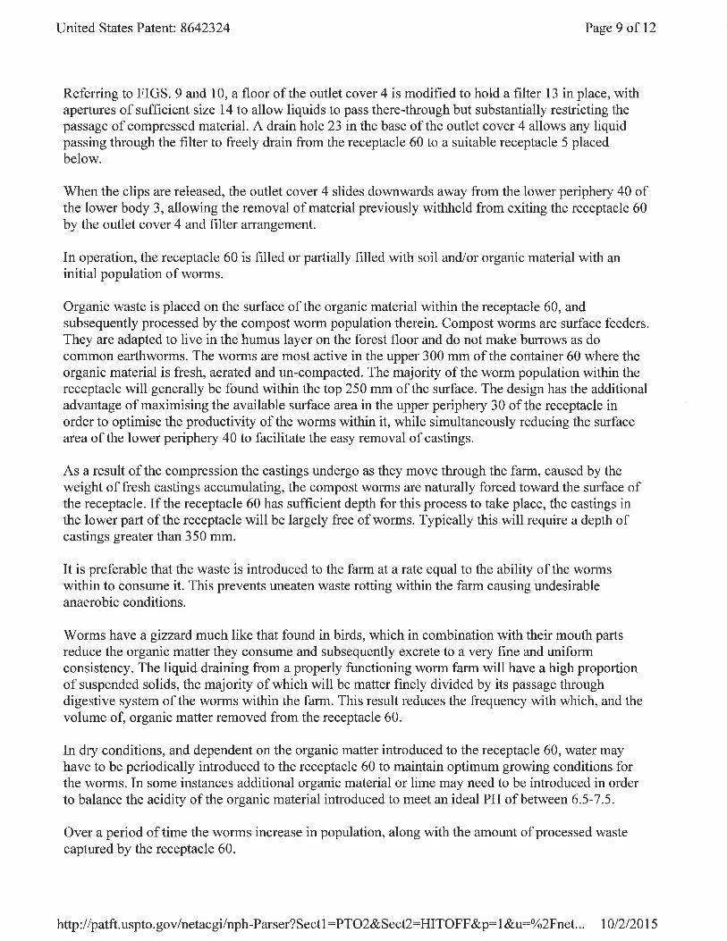
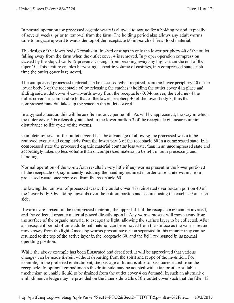
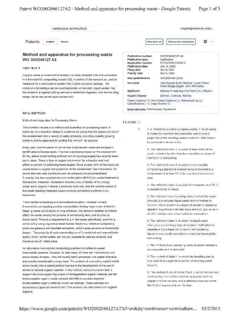
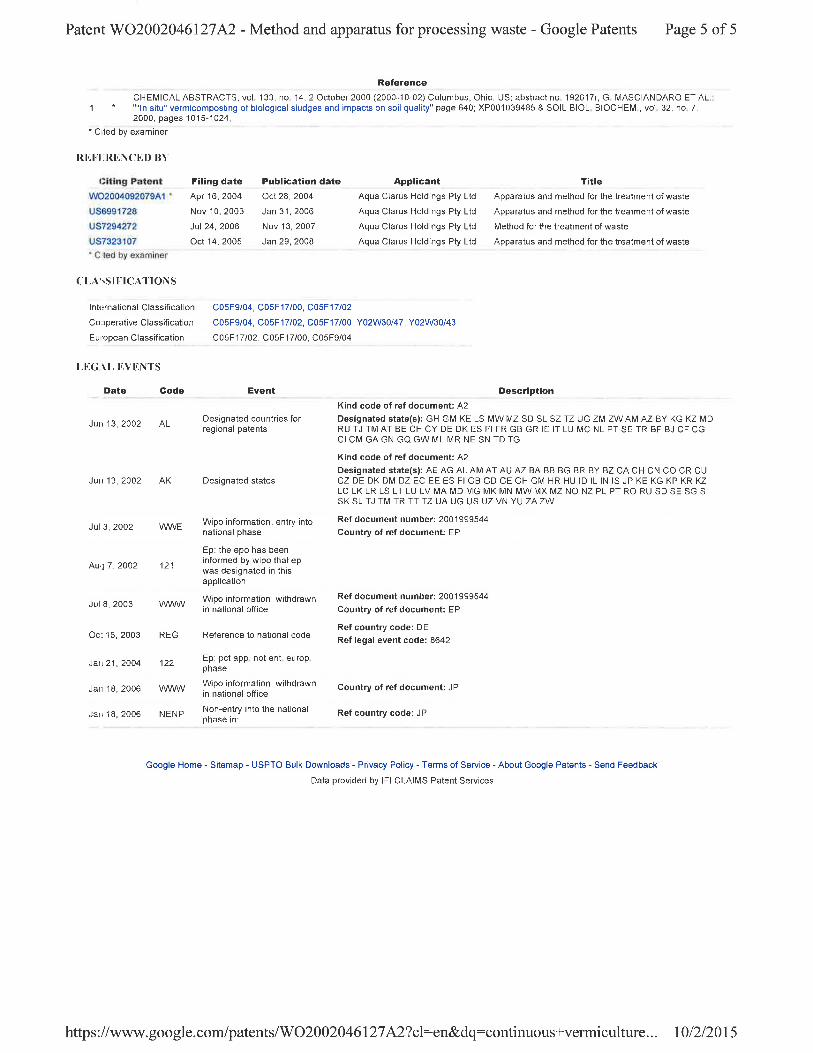
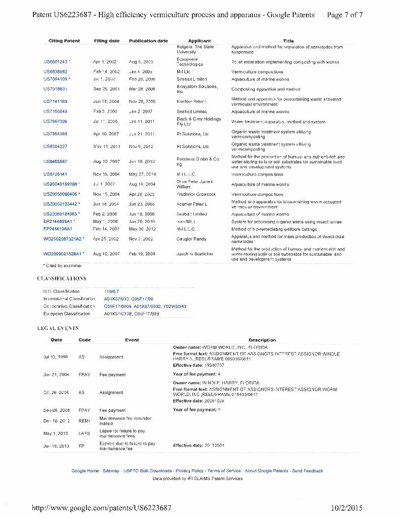
Patent ID US 6576462 B2: Published on June 10, 2003 http://patft.uspto.gov/netacgi/nph-Parser?Sect1=PTO2&Sect2=HITOFF&u=%2Fnetahtml%2FPTO%2Fsearch-adv.htm&r=12&f=G&l=50&d=PTXT&p=1&S1=%28%28vermiculture+AND+continuous%29+AND+compost%29&OS=vermiculture+AND+continuous+AND+compost&RS=%28%28vermiculture+AND+continuous%29+AND+compost%29 This is a patent for a rectangular container fabricated specifically for the composting of animal and household waste using vermiculture. The bins are painted specifically to absorb sunlight on the front end and cover (black) and to reflect sunlight on the opposite end (white). Compost is extracted via an opening adjacent to the base of the container. This is a very simplified and small vermiculture composting unit that uses the temperature gradient to draw in new oxygen and cool the increasing temperatures within the bin due to respiration. The manipulation of sunlight in order to maintain an ideal temperature within the containers could greatly assist our project. Patent ID EP 0196887 A2: Published on October 8, 1986 https://www.google.com/patents/EP0196887A2?cl=en&dq=continuous+vermiculture&hl=en&sa=X&ved=0CCoQ6AEwAmoVChMIwpykx5ikyAIVhZENCh2WjA3R This is a patent for the use of a breaker bar unit to extract the base layer of the finished compost within a unit with a perforated floor. As it separates the completed compost at the bottom of the container, it does not disrupt the worms that are near the top of the bin. This can also serve to harvest worms for the marketable venture of protein-rich feed for pig, poultry, and fish farming. Ultimately, this provides an idea for the mechanized extraction of compost after the waste products are broken down and excreted by the worms. Patent ID WO 2002046127 A2: Published on June 13, 2002 https://www.google.com/patents/WO2002046127A2?cl=en&dq=continuous+vermiculture&hl=en&sa=X&ved=0CEYQ6AEwBmoVChMIwpykx5ikyAIVhZENCh2WjA3R This is a patent for composting organic waste using a thermophilic vermiculture system in order to produce worm castings. This is a very similar system to what we are trying to implement in this project, but does not give many specifics on the technology used. This is still helpful because it describes the process and necessity of this type of system. Patent ID US 6223687 B1: Published on May 1, 2001 http://www.google.com/patents/US6223687 This is a patent for a conveying system in which a thin layer of biomass is moved along a layer of worms in order to increase their activity. This creates a continuous open system and maintains efficiency due to increased spatial awareness from the worms. The beds can then be stacked in order maximize this efficiency. This is likely a system that would greatly exceed our budget, but it is helpful because it provides insight into spatial efficiency and the continuous process we are seeking to develop. Patent ID US 7141169 B1: Published on November 28, 2006 http://www.google.com/patents/US7141169 This is a patent for the digestion and distribution of raw sewage among the bed of worms. The system controls the temperature of the waste before its dispersal among the worms through simple heating and cooling coils. While this may be slightly too intensive for our project, it provides insight about the importance of temperature control, maintenance of equipment, and the process of digestion prior to the flooding of the containers. Patent ID US 8642324 B1: Published on February 4, 2014
13 | I n f i n i t e V e r m i c a s t S o l u t i o n s
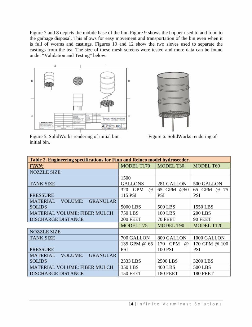
http://patft.uspto.gov/netacgi/nph-Parser?Sect1=PTO2&Sect2=HITOFF&p=1&u=%2Fnetahtml%2FPTO%2Fsearch-bool.html&r=6&f=G&l=50&co1=AND&d=PTXT&s1=vermiculture&OS=vermiculture&RS=vermiculture This is a patent for an innovative vermiculture container. The walls are so shaped as to compress the processed organic matter and to allow an effective means of loading the container with the waste. The “discharge apertures” allow for the removal of castings and compost and a base lid releases these materials. This is a very advanced container that can provide insight into the importance of the design of the receptacles. Customer Requirements Our customer, Mr. Dale Robinson, is requiring that we design and develop the technology for a continuous flow-through vermiculture system in order to treat organic wastes and to harvest digested worm castings. The castings can then be transported as nutrients for crop usage. A filtration system will be developed in order to separate the worm tea from the castings. After the flow-through system is flooded by the digester, the residual fluid or “worm tea” will be separately harvested and can be utilized in similar applications to the castings. An important requirement is to research and verify the biological specifications of the worms, and more specifically, the most desirable conditions for the utilized worms. We must find an ideal depth for proper growth and activity for the worms, and their dietary habits must also be researched in order to determine the specifications for the waste delivery system. Our vermiculture unit should be able to maintain a certain ideal volume for each individual worm in order to maximize the composting process. Ultimately, we are required to design and manufacture a prototype for a continuous waste management and composting unit utilizing vermiculture. Quantitative Engineering Specifications The initial continuous flow-through system was to be made utilizing a 55-gallon drum as the compost bed where the worms will be located. This bin diagram mockup, rendered through SolidWorks, is shown in Figure 5 and Figure 6. The new, 16 cubic foot square bin can be found in “Generation of Design Concepts”. A three-quarter horsepower garbage disposal will be used as the digester for the provided organic waste. The chopped up food waste will be combined with water and will be used to flood the bin using a sprayer. A hydroseeder will be used in order to flood the bins with the waste material and water solution. The specifications for a Finn and Reinco model hydroseeder is listed in Table 2. A relay switch will be used to activate and deactivate the hydroseeder. A venturi tube can be used to oxygenate the organic waste solution prior to flooding the container to avoid the mixture from becoming anaerobic. This is exceptionally important when trying to maintain the dissolved oxygen content of a waste slurry similar to the one used in this process. However, in the case of this prototype, a Venturi tube will be inserted into the slurry tank to oxygenate the food and water source to maintain an aerobic feeding process in order to prevent the growth of anaerobic fungi and bacteria.
14 | I n f i n i t e V e r m i c a s t S o l u t i o n s
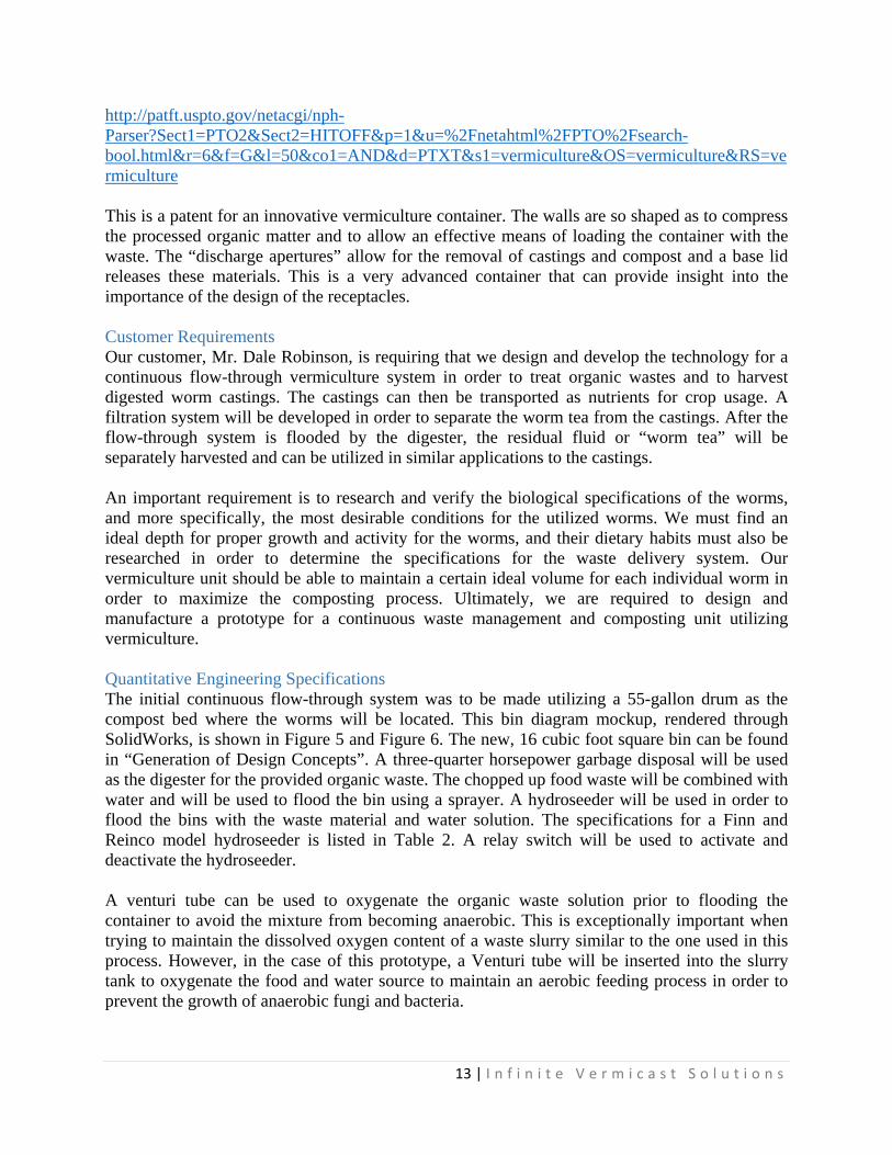
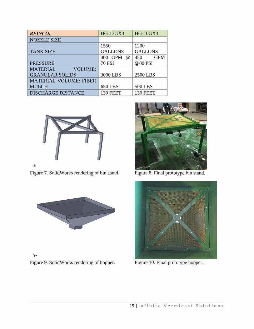
Figure 7 and 8 depicts the mobile base of the bin. Figure 9 shows the hopper used to add food to the garbage disposal. This allows for easy movement and transportation of the bin even when it is full of worms and castings. Figures 10 and 12 show the two sieves used to separate the castings from the tea. The size of these mesh screens were tested and more data can be found under “Validation and Testing” below.
Figure 5. SolidWorks rendering of initial bin. Figure 6. SolidWorks rendering of initial bin.
Table 2. Engineering specifications for Finn and Reinco model hydroseeder. FINN: MODEL T170 MODEL T30 MODEL T60 NOZZLE SIZE
TANK SIZE 1500 GALLONS 281 GALLON 500 GALLON
PRESSURE 320 GPM @ 115 PSI
65 GPM @60 PSI
65 GPM @ 75 PSI
MATERIAL VOLUME: GRANULAR SOLIDS 5000 LBS 500 LBS 1550 LBS MATERIAL VOLUME: FIBER MULCH 750 LBS 100 LBS 200 LBS DISCHARGE DISTANCE 200 FEET 70 FEET 90 FEET
MODEL T75 MODEL T90 MODEL T120 NOZZLE SIZE TANK SIZE 700 GALLON 800 GALLON 1000 GALLON
PRESSURE 135 GPM @ 65 PSI
170 GPM @ 100 PSI
170 GPM @ 100 PSI
MATERIAL VOLUME: GRANULAR SOLIDS 2333 LBS 2500 LBS 3200 LBS MATERIAL VOLUME: FIBER MULCH 350 LBS 400 LBS 500 LBS DISCHARGE DISTANCE 150 FEET 180 FEET 180 FEET
15 | I n f i n i t e V e r m i c a s t S o l u t i o n s
REINCO: HG-13GX3 HG-10GX3 NOZZLE SIZE
TANK SIZE 1550 GALLONS
1200 GALLONS
PRESSURE 400 GPM @ 70 PSI
450 GPM @80 PSI
MATERIAL VOLUME: GRANULAR SOLIDS 3000 LBS 2500 LBS MATERIAL VOLUME: FIBER MULCH 650 LBS 500 LBS DISCHARGE DISTANCE 130 FEET 130 FEET
Figure 7. SolidWorks rendering of bin stand. Figure 8. Final prototype bin stand.
Figure 9. SolidWorks rendering of hopper. Figure 10. Final prototype hopper.
16 | I n f i n i t e V e r m i c a s t S o l u t i o n s
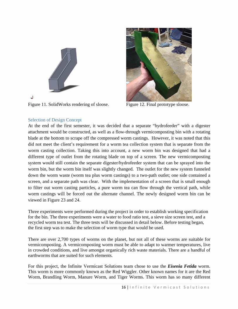
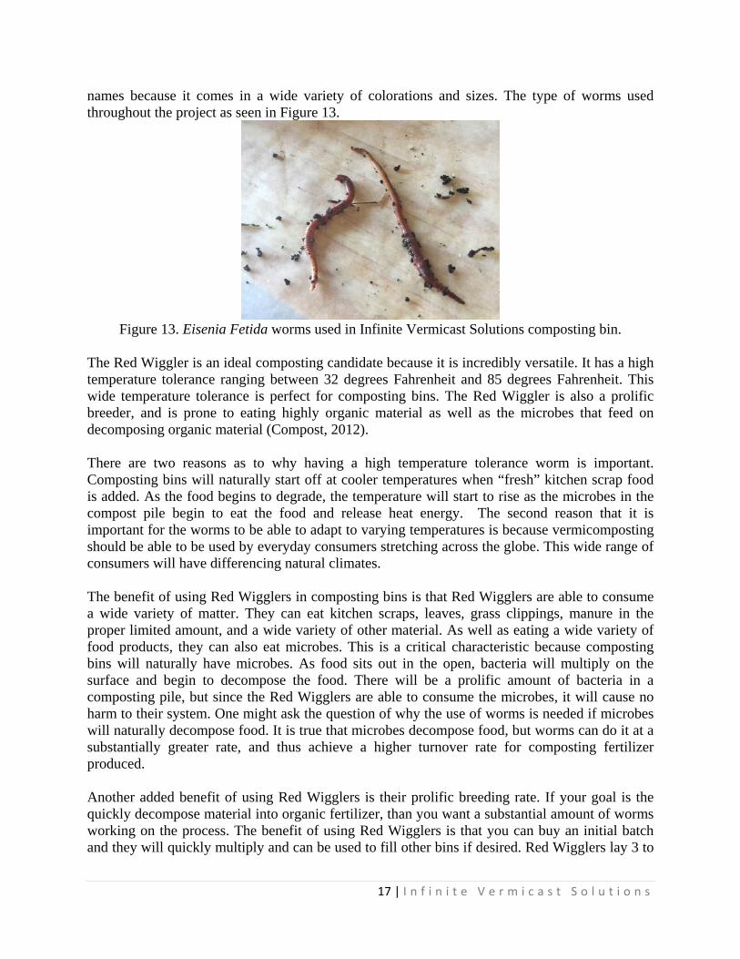
Figure 11. SolidWorks rendering of sloose. Figure 12. Final prototype sloose.
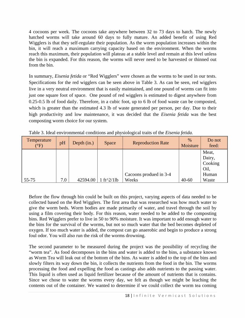
Selection of Design Concept At the end of the first semester, it was decided that a separate “hydrofeeder” with a digester attachment would be constructed, as well as a flow-through vermicomposting bin with a rotating blade at the bottom to scrape off the compressed worm castings. However, it was noted that this did not meet the client’s requirement for a worm tea collection system that is separate from the worm casting collection. Taking this into account, a new worm bin was designed that had a different type of outlet from the rotating blade on top of a screen. The new vermicomposting system would still contain the separate digester/hydrofeeder system that can be sprayed into the worm bin, but the worm bin itself was slightly changed. The outlet for the new system funneled down the worm waste (worm tea plus worm castings) to a two-path outlet; one side contained a screen, and a separate path was clear. With the implementation of a screen that is small enough to filter out worm casting particles, a pure worm tea can flow through the vertical path, while worm castings will be forced out the alternate channel. The newly designed worm bin can be viewed in Figure 23 and 24. Three experiments were performed during the project in order to establish working specification for the bin. The three experiments were a water to food ratio test, a sieve size screen test, and a recycled worm tea test. The three tests will be discussed in detail below. Before testing began, the first step was to make the selection of worm type that would be used. There are over 2,700 types of worms on the planet, but not all of these worms are suitable for vermicomposting. A vermicomposting worm must be able to adapt to warmer temperatures, live in crowded conditions, and live amongst organically rich waste materials. There are a handful of earthworms that are suited for such elements. For this project, the Infinite Vermicast Solutions team chose to use the Eisenia Fetida worm. This worm is more commonly known as the Red Wiggler. Other known names for it are the Red Worm, Brandling Worm, Manure Worm, and Tiger Worms. This worm has so many different
17 | I n f i n i t e V e r m i c a s t S o l u t i o n s
names because it comes in a wide variety of colorations and sizes. The type of worms used throughout the project as seen in Figure 13.
Figure 13. Eisenia Fetida worms used in Infinite Vermicast Solutions composting bin.
The Red Wiggler is an ideal composting candidate because it is incredibly versatile. It has a high temperature tolerance ranging between 32 degrees Fahrenheit and 85 degrees Fahrenheit. This wide temperature tolerance is perfect for composting bins. The Red Wiggler is also a prolific breeder, and is prone to eating highly organic material as well as the microbes that feed on decomposing organic material (Compost, 2012). There are two reasons as to why having a high temperature tolerance worm is important. Composting bins will naturally start off at cooler temperatures when “fresh” kitchen scrap food is added. As the food begins to degrade, the temperature will start to rise as the microbes in the compost pile begin to eat the food and release heat energy. The second reason that it is important for the worms to be able to adapt to varying temperatures is because vermicomposting should be able to be used by everyday consumers stretching across the globe. This wide range of consumers will have differencing natural climates. The benefit of using Red Wigglers in composting bins is that Red Wigglers are able to consume a wide variety of matter. They can eat kitchen scraps, leaves, grass clippings, manure in the proper limited amount, and a wide variety of other material. As well as eating a wide variety of food products, they can also eat microbes. This is a critical characteristic because composting bins will naturally have microbes. As food sits out in the open, bacteria will multiply on the surface and begin to decompose the food. There will be a prolific amount of bacteria in a composting pile, but since the Red Wigglers are able to consume the microbes, it will cause no harm to their system. One might ask the question of why the use of worms is needed if microbes will naturally decompose food. It is true that microbes decompose food, but worms can do it at a substantially greater rate, and thus achieve a higher turnover rate for composting fertilizer produced. Another added benefit of using Red Wigglers is their prolific breeding rate. If your goal is the quickly decompose material into organic fertilizer, than you want a substantial amount of worms working on the process. The benefit of using Red Wigglers is that you can buy an initial batch and they will quickly multiply and can be used to fill other bins if desired. Red Wigglers lay 3 to
18 | I n f i n i t e V e r m i c a s t S o l u t i o n s
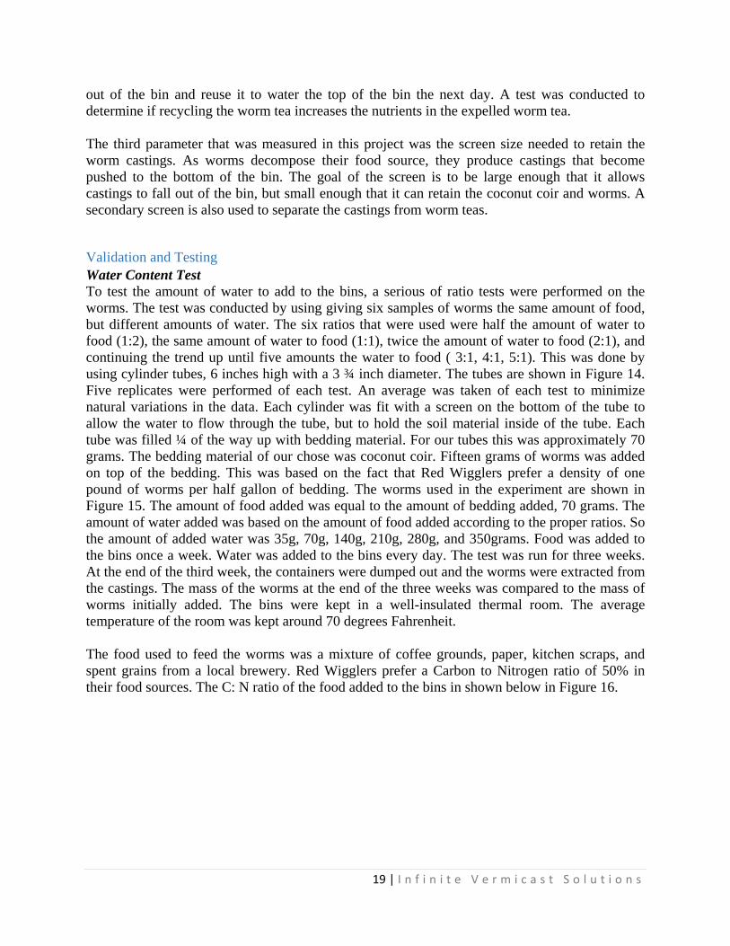
4 cocoons per week. The cocoons take anywhere between 32 to 73 days to hatch. The newly hatched worms will take around 60 days to fully mature. An added benefit of using Red Wigglers is that they self-regulate their population. As the worm population increases within the bin, it will reach a maximum carrying capacity based on the environment. When the worms reach this maximum, their population will plateau at a stable level and remain at this level unless the bin is expanded. For this reason, the worms will never need to be harvested or thinned out from the bin. In summary, Eisenia fetida or “Red Wigglers” were chosen as the worms to be used in our tests. Specifications for the red wigglers can be seen above in Table 3. As can be seen, red wigglers live in a very neutral environment that is easily maintained, and one pound of worms can fit into just one square foot of space. One pound of red wigglers is estimated to digest anywhere from 0.25-0.5 lb of food daily. Therefore, in a cubic foot, up to 6 lb of food waste can be composted, which is greater than the estimated 4.3 lb of waste generated per person, per day. Due to their high productivity and low maintenance, it was decided that the Eisenia fetida was the best composting worm choice for our system.
Table 3. Ideal environmental conditions and physiological traits of the Eisenia fetida.
Temperature (°F)
pH Depth (in.) Space Reproduction Rate %
MoistureDo not feed:
55-75 7.0 42594.00 1 ft^2/1lb Cacoons produed in 3-4 Weeks 40-60
Meat, Dairy, Cooking Oil, Human Waste
Before the flow through bin could be built on this project, varying aspects of data needed to be collected based on the Red Wigglers. The first area that was researched was how much water to give the worm beds. Worm bodies are made primarily of water, and travel through the soil by using a film covering their body. For this reason, water needed to be added to the composting bins. Red Wigglers prefer to live in 50 to 90% moisture. It was important to add enough water to the bins for the survival of the worms, but not so much water that the bed becomes depleted of oxygen. If too much water is added, the compost can go anaerobic and begin to produce a strong foul odor. You will also run the risk of the worms drowning. The second parameter to be measured during the project was the possibility of recycling the “worm tea”. As food decomposes in the bins and water is added to the bins, a substance known as Worm Tea will leak out of the bottom of the bins. As water is added to the top of the bins and slowly filters its way down the bin, it collects the nutrients from the food in the bin. The worms processing the food and expelling the food as castings also adds nutrients to the passing water. This liquid is often used as liquid fertilizer because of the amount of nutrients that is contains. Since we chose to water the worms every day, we felt as though we might be leaching the contents out of the container. We wanted to determine if we could collect the worm tea coming
19 | I n f i n i t e V e r m i c a s t S o l u t i o n s
out of the bin and reuse it to water the top of the bin the next day. A test was conducted to determine if recycling the worm tea increases the nutrients in the expelled worm tea. The third parameter that was measured in this project was the screen size needed to retain the worm castings. As worms decompose their food source, they produce castings that become pushed to the bottom of the bin. The goal of the screen is to be large enough that it allows castings to fall out of the bin, but small enough that it can retain the coconut coir and worms. A secondary screen is also used to separate the castings from worm teas.
Validation and Testing Water Content Test To test the amount of water to add to the bins, a serious of ratio tests were performed on the worms. The test was conducted by using giving six samples of worms the same amount of food, but different amounts of water. The six ratios that were used were half the amount of water to food (1:2), the same amount of water to food (1:1), twice the amount of water to food (2:1), and continuing the trend up until five amounts the water to food ( 3:1, 4:1, 5:1). This was done by using cylinder tubes, 6 inches high with a 3 ¾ inch diameter. The tubes are shown in Figure 14. Five replicates were performed of each test. An average was taken of each test to minimize natural variations in the data. Each cylinder was fit with a screen on the bottom of the tube to allow the water to flow through the tube, but to hold the soil material inside of the tube. Each tube was filled ¼ of the way up with bedding material. For our tubes this was approximately 70 grams. The bedding material of our chose was coconut coir. Fifteen grams of worms was added on top of the bedding. This was based on the fact that Red Wigglers prefer a density of one pound of worms per half gallon of bedding. The worms used in the experiment are shown in Figure 15. The amount of food added was equal to the amount of bedding added, 70 grams. The amount of water added was based on the amount of food added according to the proper ratios. So the amount of added water was 35g, 70g, 140g, 210g, 280g, and 350grams. Food was added to the bins once a week. Water was added to the bins every day. The test was run for three weeks. At the end of the third week, the containers were dumped out and the worms were extracted from the castings. The mass of the worms at the end of the three weeks was compared to the mass of worms initially added. The bins were kept in a well-insulated thermal room. The average temperature of the room was kept around 70 degrees Fahrenheit. The food used to feed the worms was a mixture of coffee grounds, paper, kitchen scraps, and spent grains from a local brewery. Red Wigglers prefer a Carbon to Nitrogen ratio of 50% in their food sources. The C: N ratio of the food added to the bins in shown below in Figure 16.

20 | I n f i n i t e V e r m i c a s t S o l u t i o n s
Figure 14. Testing bins for experimentation. Figure 15. Red Wigglers used in experimentation.
Figure 16. Estimated Carbon to Nitrogen Ratio of food slurry utilized in testing.
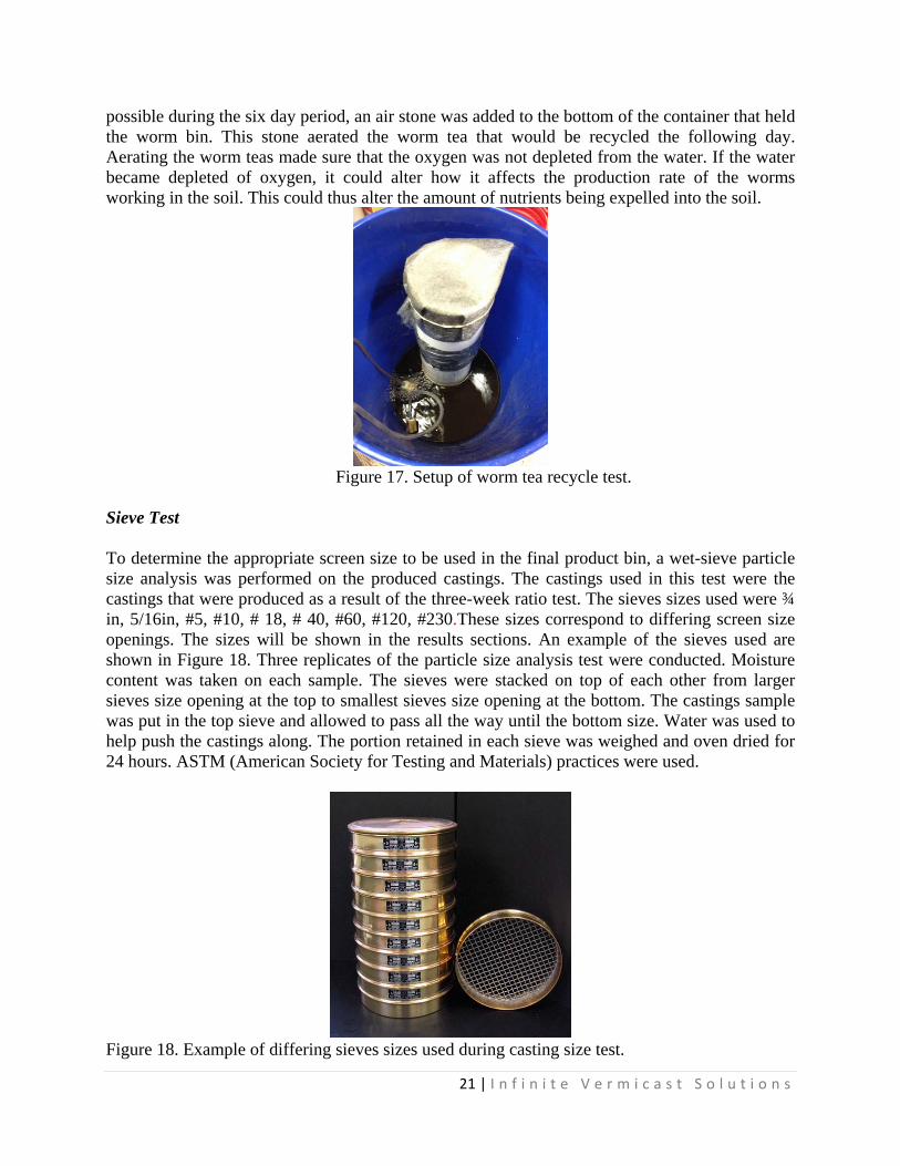
Worm Tea Recycle Test To conduct this experiment, the same containers were used that were used in the ratio test. The same proportions were also used; 70g of coir, 70g of food, and 15g of worms. The amount of water used was determined how much water was needed to produce an expulsion of water at the bottom of the container. The water was poured into the top of the container each day for six consistent days. A collection of water was taken each day from the worm tea and sent to a water processing lab. Figure 17 shows the setup of the recycle test. The amount of Nitrogen, Phosphorous, and Potassium was measured in each sample. To keep all parameters as constant as
21 | I n f i n i t e V e r m i c a s t S o l u t i o n s
possible during the six day period, an air stone was added to the bottom of the container that held the worm bin. This stone aerated the worm tea that would be recycled the following day. Aerating the worm teas made sure that the oxygen was not depleted from the water. If the water became depleted of oxygen, it could alter how it affects the production rate of the worms working in the soil. This could thus alter the amount of nutrients being expelled into the soil.
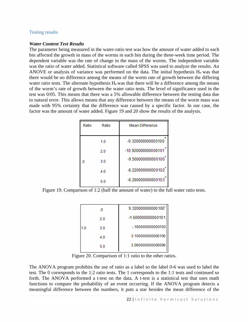
Figure 17. Setup of worm tea recycle test. Sieve Test To determine the appropriate screen size to be used in the final product bin, a wet-sieve particle size analysis was performed on the produced castings. The castings used in this test were the castings that were produced as a result of the three-week ratio test. The sieves sizes used were ¾ in, 5/16in, #5, #10, # 18, # 40, #60, #120, #230.These sizes correspond to differing screen size openings. The sizes will be shown in the results sections. An example of the sieves used are shown in Figure 18. Three replicates of the particle size analysis test were conducted. Moisture content was taken on each sample. The sieves were stacked on top of each other from larger sieves size opening at the top to smallest sieves size opening at the bottom. The castings sample was put in the top sieve and allowed to pass all the way until the bottom size. Water was used to help push the castings along. The portion retained in each sieve was weighed and oven dried for 24 hours. ASTM (American Society for Testing and Materials) practices were used.
Figure 18. Example of differing sieves sizes used during casting size test.
22 | I n f i n i t e V e r m i c a s t S o l u t i o n s
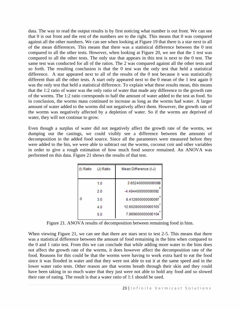
Testing results Water Content Test Results The parameter being measured in the water-ratio test was how the amount of water added to each bin affected the growth in mass of the worms in each bin during the three-week time period. The dependent variable was the rate of change in the mass of the worms. The independent variable was the ratio of water added. Statistical software called SPSS was used to analyze the results. An ANOVE or analysis of variance was performed on the data. The initial hypothesis Ho was that there would be no difference among the means of the worm rate of growth between the differing water ratio tests. The alternate hypothesis Ha was that there will be a difference among the means of the worm’s rate of growth between the water ratio tests. The level of significance used in the test was 0/05. This means that there was a 5% allowable difference between the testing data due to natural error. This allows means that any difference between the means of the worm mass was made with 95% certainty that the difference was caused by a specific factor. In our case, the factor was the amount of water added. Figure 19 and 20 show the results of the analysis.
Figure 19. Comparison of 1:2 (half the amount of water) to the full water ratio tests.
Figure 20. Comparison of 1:1 ratio to the other ratios.
The ANOVA program prohibits the use of ratio as a label so the label 0-6 was used to label the test. The 0 corresponds to the 1:2 ratio tests. The 1 corresponds to the 1:1 tests and continued so forth. The ANOVA performed a t-test on the data. A t-test is a statistical test that uses math functions to compare the probability of an event occurring. If the ANOVA program detects a meaningful difference between the numbers, it puts a star besides the mean difference of the
23 | I n f i n i t e V e r m i c a s t S o l u t i o n s
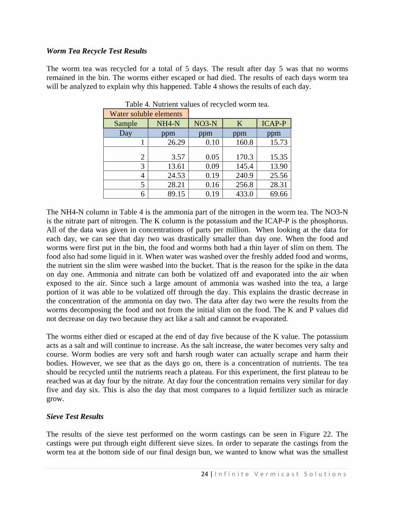
data. The way to read the output results is by first noticing what number is out front. We can see that 0 is out front and the rest of the numbers are to the right. This means that 0 was compared against all the other numbers. We can see when looking at Figure 19 that there is a star next to all of the mean differences. This means that there was a statistical difference between the 0 test compared to all the other tests. However, when looking at Figure 20, we see that the 1 test was compared to all the other tests. The only star that appears in this test is next to the 0 test. The same test was conducted for all of the ratios. The 2 was compared against all the other tests and so forth. The resulting conclusion is that the 0 test was the only test that held a statistical difference. A star appeared next to all of the results of the 0 test because it was statistically different than all the other tests. A start only appeared next to the 0 mean of the 1 test again 0 was the only test that held a statistical difference. To explain what these results mean, this means that the 1:2 ratio of water was the only ratio of water that made any difference to the growth rate of the worms. The 1:2 ratio corresponds to half the amount of water added to the test as food. So in conclusion, the worms mass continued to increase as long as the worms had water. A larger amount of water added to the worms did not negatively affect them. However, the growth rate of the worms was negatively affected by a depletion of water. So if the worms are deprived of water, they will not continue to grow. Even though a surplus of water did not negatively affect the growth rate of the worms, we dumping out the castings, we could visibly see a difference between the amounts of decomposition in the added food source. Since all the parameters were measured before they were added to the bin, we were able to subtract out the worms, coconut coir and other variables in order to give a rough estimation of how much food source remained. An ANOVA was performed on this data. Figure 21 shows the results of that test.
Figure 21. ANOVA results of decomposition between remaining food in bins.
When viewing Figure 21, we can see that there are stars next to test 2-5. This means that there was a statistical difference between the amount of food remaining in the bins when compared to the 0 and 1 ratio test. From this we can conclude that while adding more water to the bins does not affect the growth rate of the worms, it does however affect the decomposition rate of the food. Reasons for this could be that the worms were having to work extra hard to eat the food since it was flooded in water and that they were not able to eat it at the same speed and in the lower water ratio tests. Other reason are that worms breath through their skin and they could have been taking in so much water that they just were not able to hold any food and so slowed their rate of eating. The result is that a water ratio of 1:1 should be used.
24 | I n f i n i t e V e r m i c a s t S o l u t i o n s
Worm Tea Recycle Test Results The worm tea was recycled for a total of 5 days. The result after day 5 was that no worms remained in the bin. The worms either escaped or had died. The results of each days worm tea will be analyzed to explain why this happened. Table 4 shows the results of each day.
Table 4. Nutrient values of recycled worm tea.
Water soluble elements Sample NH4-N NO3-N K ICAP-P
Day ppm ppm ppm ppm 1 26.29 0.10 160.8 15.73
2 3.57 0.05 170.3 15.35 3 13.61 0.09 145.4 13.90 4 24.53 0.19 240.9 25.56 5 28.21 0.16 256.8 28.31 6 89.15 0.19 433.0 69.66
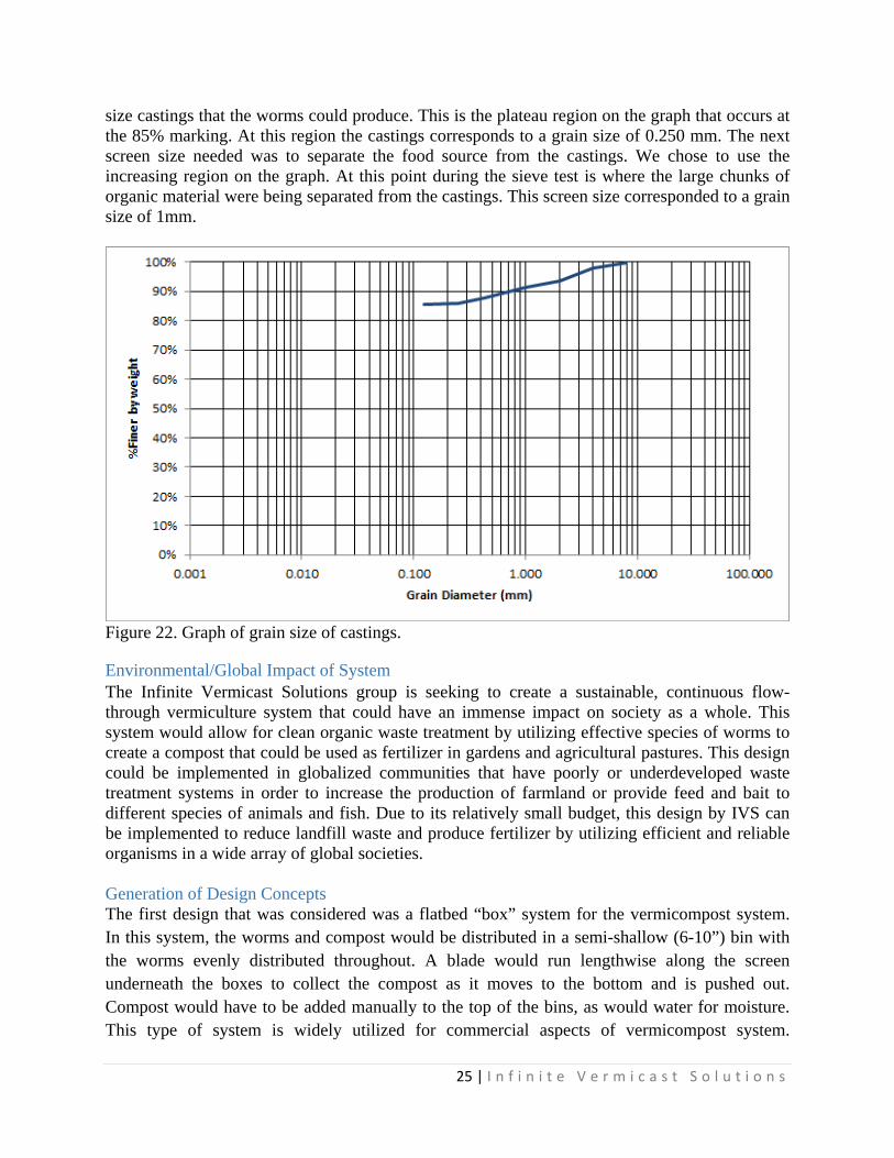
The NH4-N column in Table 4 is the ammonia part of the nitrogen in the worm tea. The NO3-N is the nitrate part of nitrogen. The K column is the potassium and the ICAP-P is the phosphorus. All of the data was given in concentrations of parts per million. When looking at the data for each day, we can see that day two was drastically smaller than day one. When the food and worms were first put in the bin, the food and worms both had a thin layer of slim on them. The food also had some liquid in it. When water was washed over the freshly added food and worms, the nutrient sin the slim were washed into the bucket. That is the reason for the spike in the data on day one. Ammonia and nitrate can both be volatized off and evaporated into the air when exposed to the air. Since such a large amount of ammonia was washed into the tea, a large portion of it was able to be volatized off through the day. This explains the drastic decrease in the concentration of the ammonia on day two. The data after day two were the results from the worms decomposing the food and not from the initial slim on the food. The K and P values did not decrease on day two because they act like a salt and cannot be evaporated. The worms either died or escaped at the end of day five because of the K value. The potassium acts as a salt and will continue to increase. As the salt increase, the water becomes very salty and course. Worm bodies are very soft and harsh rough water can actually scrape and harm their bodies. However, we see that as the days go on, there is a concentration of nutrients. The tea should be recycled until the nutrients reach a plateau. For this experiment, the first plateau to be reached was at day four by the nitrate. At day four the concentration remains very similar for day five and day six. This is also the day that most compares to a liquid fertilizer such as miracle grow. Sieve Test Results The results of the sieve test performed on the worm castings can be seen in Figure 22. The castings were put through eight different sieve sizes. In order to separate the castings from the worm tea at the bottom side of our final design bun, we wanted to know what was the smallest
25 | I n f i n i t e V e r m i c a s t S o l u t i o n s
size castings that the worms could produce. This is the plateau region on the graph that occurs at the 85% marking. At this region the castings corresponds to a grain size of 0.250 mm. The next screen size needed was to separate the food source from the castings. We chose to use the increasing region on the graph. At this point during the sieve test is where the large chunks of organic material were being separated from the castings. This screen size corresponded to a grain size of 1mm.
Figure 22. Graph of grain size of castings.
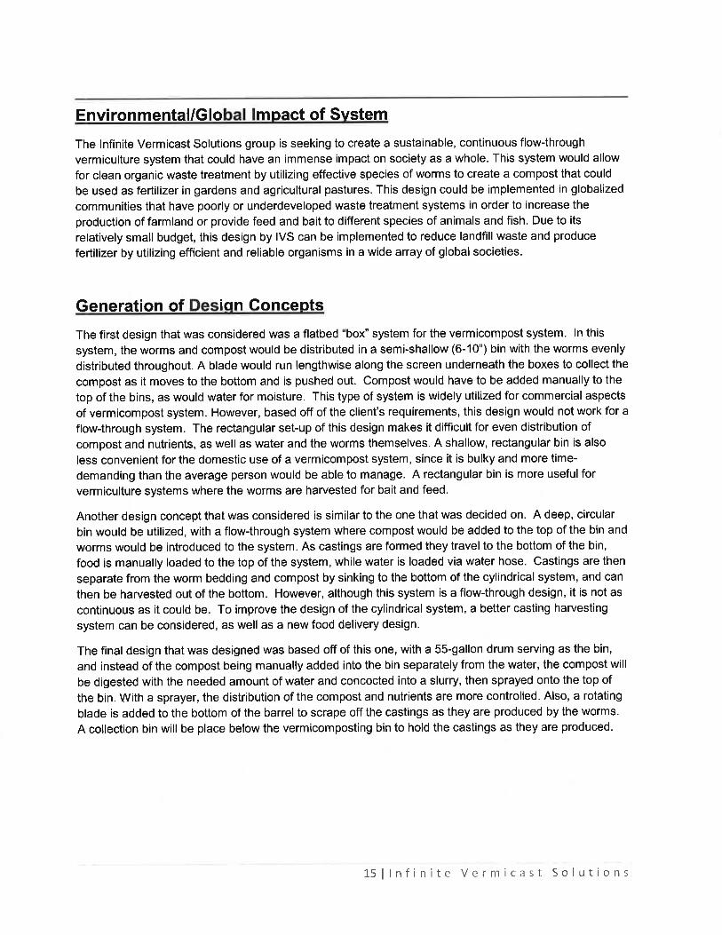
Environmental/Global Impact of System The Infinite Vermicast Solutions group is seeking to create a sustainable, continuous flow-through vermiculture system that could have an immense impact on society as a whole. This system would allow for clean organic waste treatment by utilizing effective species of worms to create a compost that could be used as fertilizer in gardens and agricultural pastures. This design could be implemented in globalized communities that have poorly or underdeveloped waste treatment systems in order to increase the production of farmland or provide feed and bait to different species of animals and fish. Due to its relatively small budget, this design by IVS can be implemented to reduce landfill waste and produce fertilizer by utilizing efficient and reliable organisms in a wide array of global societies. Generation of Design Concepts The first design that was considered was a flatbed “box” system for the vermicompost system. In this system, the worms and compost would be distributed in a semi-shallow (6-10”) bin with the worms evenly distributed throughout. A blade would run lengthwise along the screen underneath the boxes to collect the compost as it moves to the bottom and is pushed out. Compost would have to be added manually to the top of the bins, as would water for moisture. This type of system is widely utilized for commercial aspects of vermicompost system.
26 | I n f i n i t e V e r m i c a s t S o l u t i o n s
However, based off of the client’s requirements, this design would not work for a flow-through system. The rectangular set-up of this design makes it difficult for even distribution of compost and nutrients, as well as water and the worms themselves. A shallow, rectangular bin is also less convenient for the domestic use of a vermicompost system, since it is bulky and more time-demanding than the average person would be able to manage. A rectangular bin is more useful for vermiculture systems where the worms are harvested for bait and feed. Another design concept that was considered is similar to the one that was decided on. A deep, circular bin would be utilized, with a flow-through system where compost would be added to the top of the bin and worms would be introduced to the system. As castings are formed they travel to the bottom of the bin, food is manually loaded to the top of the system, while water is loaded via water hose. Castings are then separate from the worm bedding and compost by sinking to the bottom of the cylindrical system, and can then be harvested out of the bottom. However, although this system is a flow-through design, it is not as continuous as it could be. To improve the design of the cylindrical system, a better casting harvesting system can be considered, as well as a new food delivery design. The chosen prototype by the end of the first design period was based off of this one, with a 55-gallon drum serving as the bin, and instead of the compost being manually added into the bin separately from the water, the compost will be digested with the needed amount of water and concocted into a slurry, then sprayed onto the top of the bin. With a sprayer, the distribution of the compost and nutrients are more controlled. Also, a rotating blade is added to the bottom of the barrel to scrape off the castings as they are produced by the worms. A collection bin will be place below the vermicomposting bin to hold the castings as they are produced. Once drafting of the design began, it was quickly discovered that the rotating blade added unnecessary complications, and the client was also requiring that the system have an implement that would separate the worm castings from the “worm tea”, so the bin that was to be constructed was redesigned. While the design of the feeding system remained the same, the bin outlet would have two paths. One path is made for solids, while the other path is where the “worm tea” is to drain out. The vertical path will draw the worm tea out the bottom of the system with a proper screen size to act as a filter and block the castings from exiting. The castings will then go out the second path, therefore separating the two. With the worm tea already separated from the castings, each one can be separately used/marketed. The benefits of separating worm tea from the castings is that it can be sprayed as a fertilizer source in lieu of commercial plant growth sprays, i.e., MiracleGro. If the castings and tea came out as one product, the ammonia and other nutrient concentrations would potential be too high, which would in fact hinder the growth of plants. By spraying it on separately, the concentrations going onto the plants can be controlled.
27 | I n f i n i t e V e r m i c a s t S o l u t i o n s
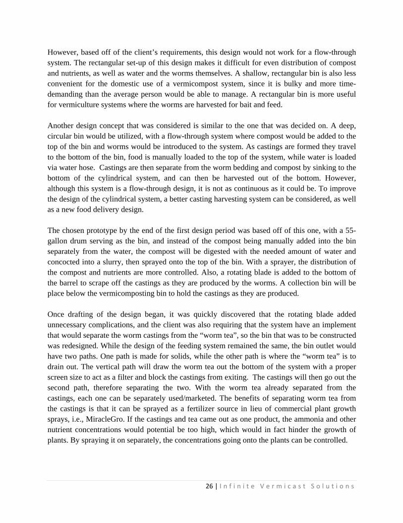
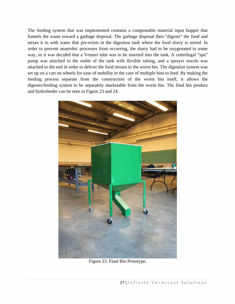
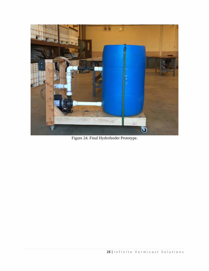
The feeding system that was implemented contains a compostable material input hopper that funnels the waste toward a garbage disposal. The garbage disposal then “digests” the food and mixes it in with water that pre-exists in the digestion tank where the food slurry is stored. In order to prevent anaerobic processes from occurring, the slurry had to be oxygenated in some way, so it was decided that a Venturi tube was to be inserted into the tank. A centrifugal “spa” pump was attached to the outlet of the tank with flexible tubing, and a sprayer nozzle was attached to the end in order to deliver the food stream to the worm bin. The digestion system was set up on a cart on wheels for ease of mobility in the case of multiple bins to feed. By making the feeding process separate from the construction of the worm bin itself, it allows the digester/feeding system to be separately marketable from the worm bin. The final bin product and hydrofeeder can be seen in Figure 23 and 24.
Figure 23. Final Bin Prototype.
28 | I n f i n i t e V e r m i c a s t S o l u t i o n s
Figure 24. Final Hydrofeeder Prototype.
29 | I n f i n i t e V e r m i c a s t S o l u t i o n s
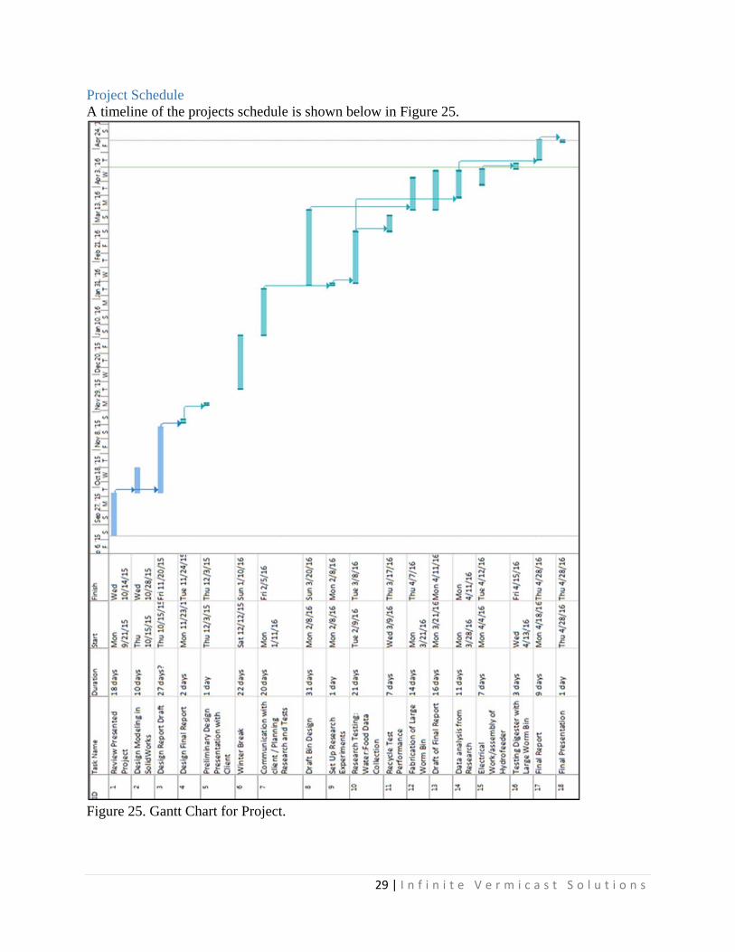
Project Schedule A timeline of the projects schedule is shown below in Figure 25.
Figure 25. Gantt Chart for Project.
30 | I n f i n i t e V e r m i c a s t S o l u t i o n s
Financial Analysis
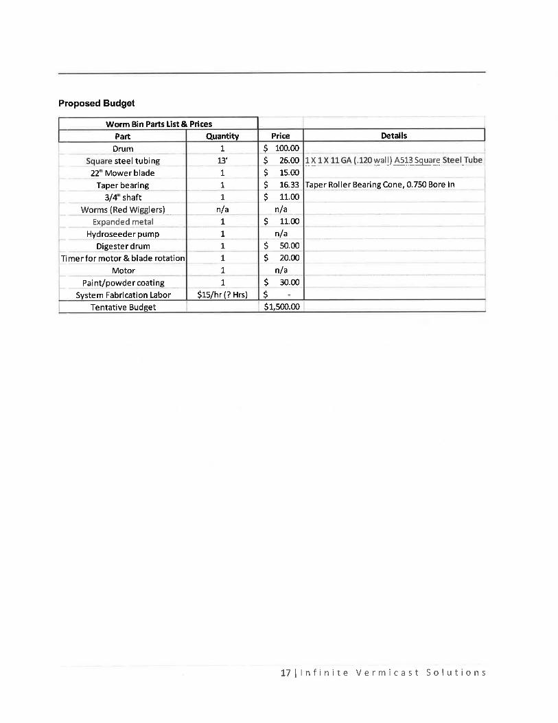
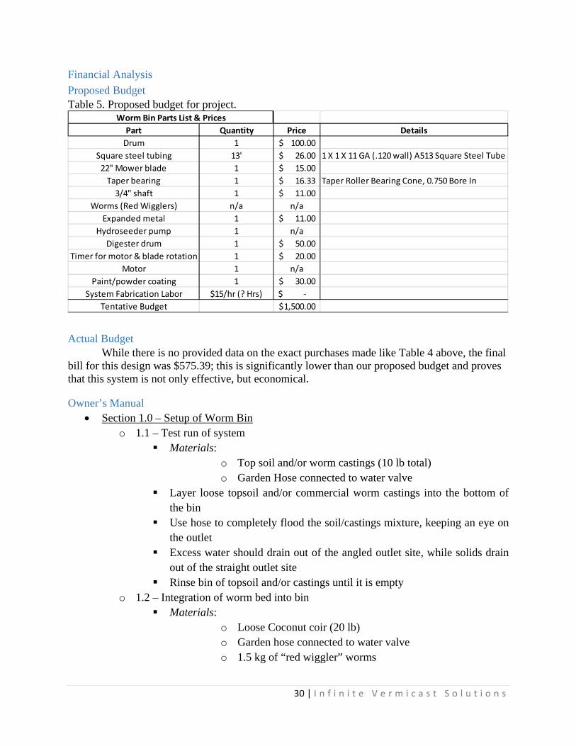
Proposed Budget Table 5. Proposed budget for project.
Actual Budget While there is no provided data on the exact purchases made like Table 4 above, the final bill for this design was $575.39; this is significantly lower than our proposed budget and proves that this system is not only effective, but economical.
Owner’s Manual Section 1.0 – Setup of Worm Bin
o 1.1 – Test run of system Materials:
o Top soil and/or worm castings (10 lb total) o Garden Hose connected to water valve
Layer loose topsoil and/or commercial worm castings into the bottom of the bin
Use hose to completely flood the soil/castings mixture, keeping an eye on the outlet
Excess water should drain out of the angled outlet site, while solids drain out of the straight outlet site
Rinse bin of topsoil and/or castings until it is empty o 1.2 – Integration of worm bed into bin
Materials: o Loose Coconut coir (20 lb) o Garden hose connected to water valve o 1.5 kg of “red wiggler” worms
Part Quantity Price Details
Drum 1 100.00$
Square steel tubing 13' 26.00$ 1 X 1 X 11 GA (.120 wall) A513 Square Steel Tube
22" Mower blade 1 15.00$
Taper bearing 1 16.33$ Taper Roller Bearing Cone, 0.750 Bore In
3/4" shaft 1 11.00$
Worms (Red Wigglers) n/a n/a
Expanded metal 1 11.00$
Hydroseeder pump 1 n/a
Digester drum 1 50.00$
Timer for motor & blade rotation 1 20.00$
Motor 1 n/a
Paint/powder coating 1 30.00$
System Fabrication Labor $15/hr (? Hrs) ‐$
Tentative Budget 1,500.00$
Worm Bin Parts List & Prices
31 | I n f i n i t e V e r m i c a s t S o l u t i o n s
Layer the coconut coir on the bottom of the worm bin Spray the coconut coir with hose until it is completely saturated with water
(water should come out the liquid outlet of bin) Place worms on top of coconut coir bedding once water is fully absorbed
into coir
Section 2.0 – Set up of Digester/Feeder o 2.1 – Initial run of the digester
Materials: o Digester/Feeder System o Wall outlet within proximity o Water hose
Fill the digester up approximately ¼ of the way with water Plug the Digester into the nearby wall outlet Switch the power button to the “ON” position (located on black box) Water should pump through system – if not, contact Support
Section 3.0 – Using the Digester with the Worm Bin o 3.1 – Digestion of food/waste material
Materials: o Waste material to be composted o Digester/Feeder System o Water Hose
Continue to fill up the digester to 1/3 of the way full Toss the waste material into the digester system Plug the digester system in and power on Food should be drawn into the pump system and recirculated back through
– if not, contact Support o 3.2 – Spraying waste into worm bin
Materials: o Digester system with pre-digested food (See Sec. 3.1) o Worm bin from Sec. 1.2
Turn the digester system on Once good circulation throughout system is achieved, use nozzle to spray
digested material into worm bed Spray until about 2 in. of digested material is on the worm bed, or until
waste material has run out (whichever occurs first)
For Support, contact Infinite Vermicast Solutions at: (614)-256-2361 or [email protected]
32 | I n f i n i t e V e r m i c a s t S o l u t i o n s
Citations Patents Bell, Benjamin. 2014. Continuous flow worm farm. U.S. Patent No. 8,642,324. Gilchrist, John Ronald Scott; Totten, Lynne; Eggen, Albert Briggs; Mccluskey, John. 2002.
Method and apparatus for processing waste. WO 2002046127 A2. Koehler, Peter L. 2006. Method and apparatus for biosustaining waste activated vermicular
environment. US 7141169 B2. Jardine, Miguel. 2014. System and method for continuous vermiculture cycle. U.S. Patent No.
8,919,282 Price, James Stanley; Fletcher, Keith Ernest; Billington, Richard Stephen; Wilkin, Arthur
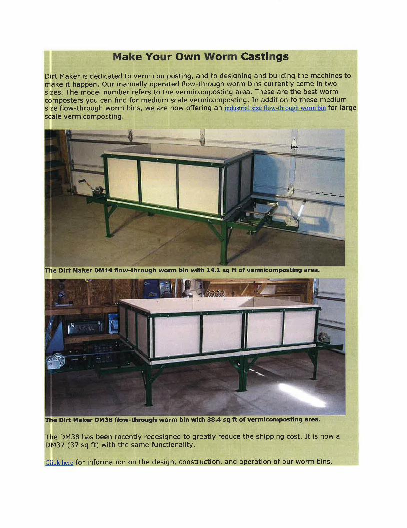
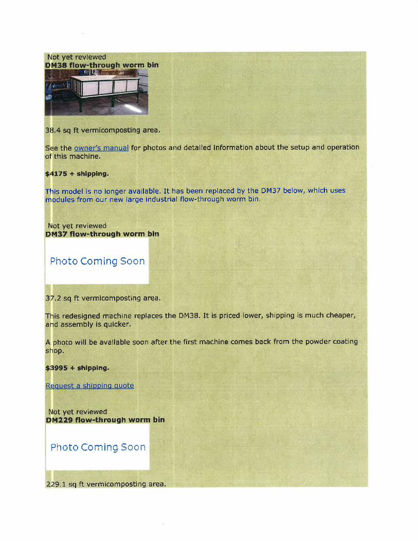
Leonard; Phillips, Victor Roger. 1986. Vermicomposting system. E.P. 0196887 A2. Thompson, Michael J. 2003. Vermiculture composting device. U.S. Patent No. 6,576,642. Windle, Harry. 2001. High efficiency vermiculture process and apparatus. US 6223687 B1. Online Materials 2014. Make Your Own Worm Castings. Gardnerville, NV: Dirt Maker Flow-Through Worm
Bins: Innovative Vermicomposting Equipment. Available at: http://dirtmaker.com/cgi-bin/contact.cgi. Accessed 02 October 2015.
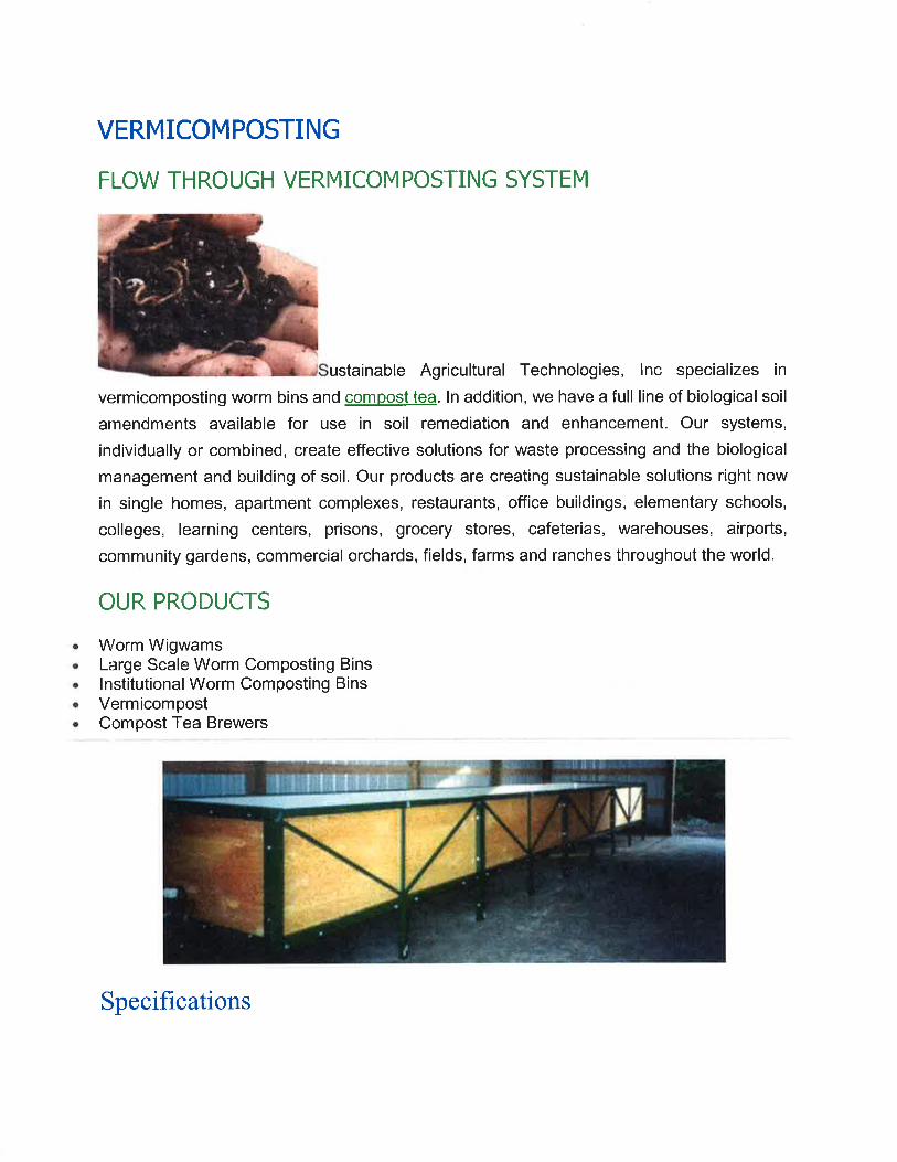
2012. Worm Wigwam Worm Bin Pricing. Cottage Grove, OR: Sustainable Agricultural Technologies, Inc. Available at: http://www.wormwigwam.com/worm-wigwam-worm-bin-pricing/. Accessed 02 October 2015.
2015. Quick Facts About Worm Composting. Red Worm Composting. Available at: http://www.redwormcomposting.com/quick-facts-about-worm-composting/. Accessed 14 April 2016.
2016. How much do we waste daily? Duke University: Center for Sustainability & Commerce. Available at: https://center.sustainability.duke.edu/resources/green-facts-consumers/how-much-do-we-waste-daily. Accessed 15 April 2016.
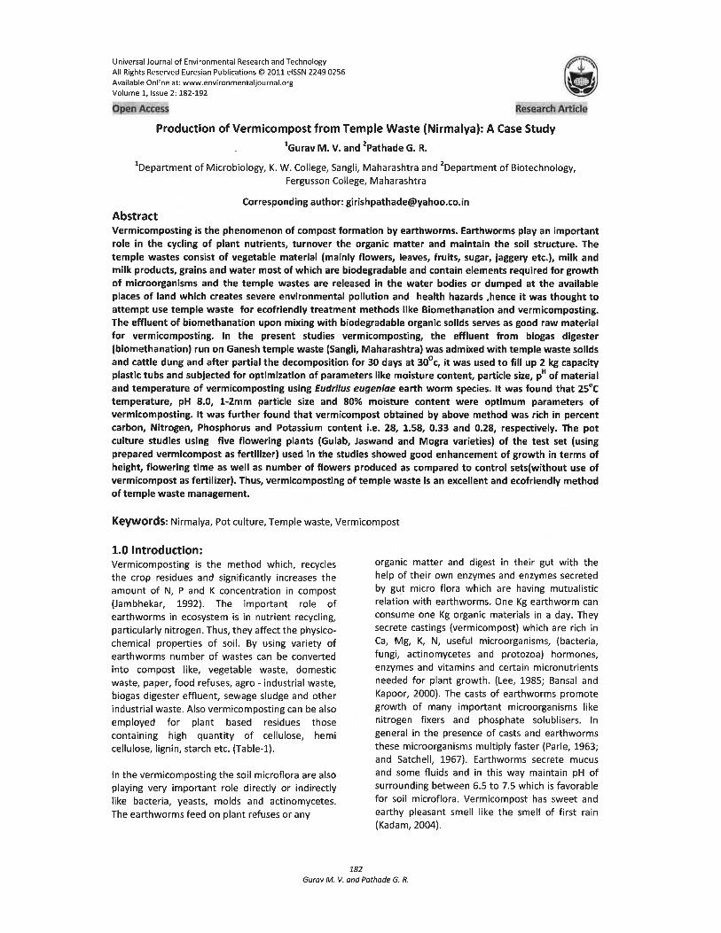
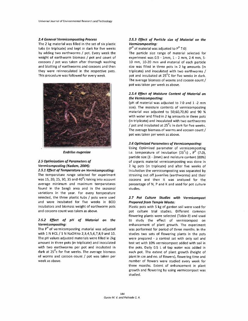
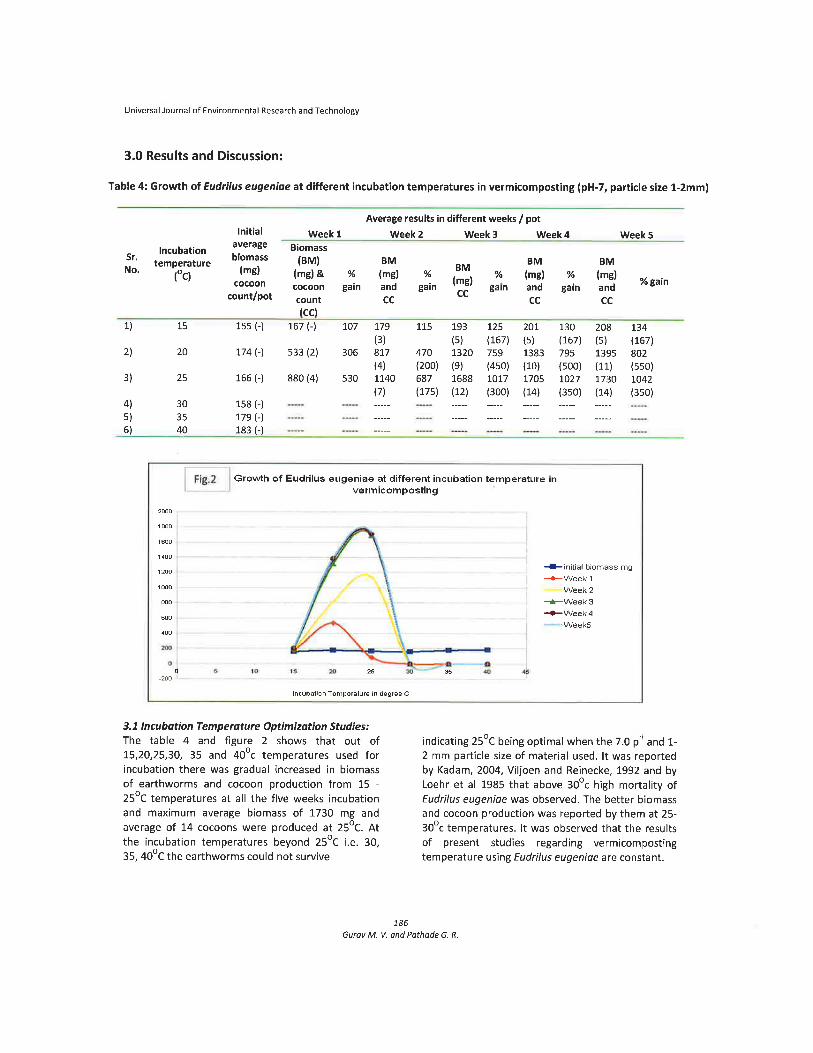
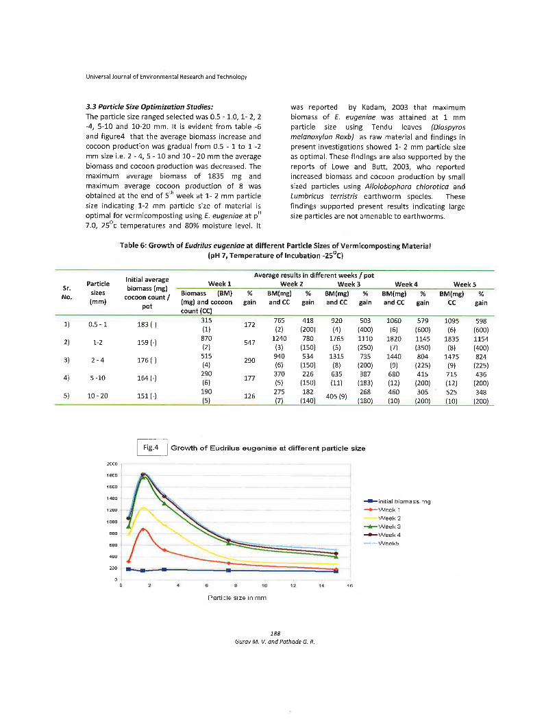
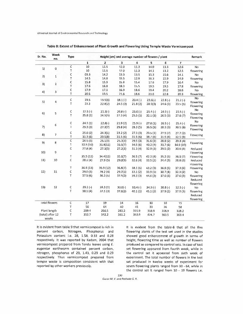
Journal Articles Gurav M. V. and Pathade, G. R. 2011. Production of Vermicompost from Temple Waste
(Nirmalya): A Case Study. Universal Journal of Environmental Research and Technology. Volume 1, Issue 2: 182-192.