Embed Size (px)
Citation preview

Rev B Doc.6001016
Doc.. 6001016Doc.. 6001016Doc.. 6001016Doc.. 6001016
Rev BRev BRev BRev B
INFINITYINFINITYINFINITYINFINITYINSTALLATION INSTRUCTIONSWITH MULTI-LINK FIRMWARE
Software Rev. 2.0 and up

Doc. 6001016 Rev B
TABLE OF CONTENTS
IMPORTANT NOTICES .............................................................................................................1
INSTALLATION TIPS ................................................................................................................1
PART 1 ARRANGING PHONE LINE INSTALLATION.............................................................3
PART 2 WIRING BETWEEN UNITS.........................................................................................3
PART 3 MOUNTING THE CABINET ........................................................................................4
PART 4 WIRING .......................................................................................................................6A. TELEPHONE INTERFACE BOARD CONNECTIONS ............................................................................ 6B. PROCESSOR BOARD SIGNAL CONNECTIONS .................................................................................. 7C. OPTIONAL CLOSED CIRCUIT TELEVISION CONNECTIONS............................................................. 8D. CONNECTING UNITS IN A CHAIN ........................................................................................................ 9E. INSTALLING A NEW UNIT IN AN EXISTING MULTI-LINK CHAIN...................................................... 11F. POWER CONNECTIONS...................................................................................................................... 12G. POWER ON .......................................................................................................................................... 13
PART 5 INSTALLING ADDITIONAL FEATURES ..................................................................14A. POSTAL LOCK INSTALLATION ........................................................................................................... 14B. AUXILIARY OPENING/REQUEST ACCESS DEVICES........................................................................ 14C. DOOR POSITION SENSING ................................................................................................................ 14D. BAUD RATE FOR RS-232 COMMUNICATION.................................................................................... 15E. HOOKING UP A STAND-ALONE MODEM........................................................................................... 15F. HOOKING UP A TERMINAL ................................................................................................................. 15G. HOOKING UP A PRINTER ................................................................................................................... 17H. HOOKING UP REMOTE KEYPADS/KEYPAD LIGHTS........................................................................ 19I. HOOKING UP CARD READERS............................................................................................................ 19J. HOOKING UP BUILT-IN MODEM/REMOTE PROGRAMMING/MULTIPLE ENTRY ............................ 21K. HOOKING UP OPTIONAL CCTV.......................................................................................................... 21
PART 6 INSTALLING THE AUXILIARY RELAY MODULE....................................................22
PART 7 TESTING AND ADJUSTING THE UNITS .................................................................24A. SEQUENCE THE UNITS IN THE CHAIN.............................................................................................. 24B. LCD DISPLAY/FAN OPTION................................................................................................................. 24C. TELEPHONE ENTRY............................................................................................................................ 25D. CARD ENTRY ....................................................................................................................................... 27E. CODE ENTRY ....................................................................................................................................... 28F. POSTAL LOCK, REQUEST FOR ACCESS, DOOR POSITION MONITORING .................................. 28G. BUILT-IN MODEM................................................................................................................................. 28H. MULTIPLE ENTRY................................................................................................................................ 28I. METHOD OF DIALING ........................................................................................................................... 28J. OPTIONAL CCTV MONITORING.......................................................................................................... 29
FCC REQUIREMENTS............................................................................................................30
DOC REQUIREMENTS ...........................................................................................................31

Rev B Doc.6001016
TABLE OF FIGURES
Figure 1. Mounting the Cabinet. .....................................................................................................4
Figure 2. Telephone Interface Board Connections. ........................................................................6
Figure 3. Infinity Circuit Board Connections. ..................................................................................7
Figure 4. Optional CCTV Unit.........................................................................................................8
Figure 5. Connecting Multiple Units Via RS-232 Ports. ..................................................................9
Figure 6. Connecting Multiple Units Through Short-Haul Modems. .............................................. 10
Figure 7. Dual Short-Haul Modem................................................................................................ 10
Figure 8. Direct Connection Between Computer and Unit 1 of Multi-Link Chain. .......................... 16
Figure 9. PC/Terminal Connected to First Infinity in a Chain Via Stand Alone Modem. ................ 17
Figure 10. Printer Connected to Last Unit of Multi-Link Chain. ..................................................... 18
Figure 11. Auxiliary Relay Module. ............................................................................................... 23
Figure 12. Telephone Interface Boards, Adjustments and Indicators. .......................................... 25
Figure 13. CCTV Power Supply Board J1 Connector. .................................................................. 29
COPYRIGHT 2000
ALL RIGHTS RESERVED
This document is protected by copyright and may not be copied or adapted without the prior writtenconsent of Sentex. This documentation contains information which is proprietary to Sentex and suchinformation may not be distributed without the prior written consent of Sentex. The software andfirmware included in the Sentex Infinity system as they relate to this documentation are also protected bycopyright and contain information proprietary to Sentex.
Sentex Systems
Chatsworth, CA
Visit us at www.sentexsystems.com

Doc. 6001016 Rev B

Rev B Doc. 6001016 Page 1 of 31
IMPORTANT NOTICESThe Infinities are powerful and flexible access control systems, but may be damaged by incorrect installation.In particular, it is critical that Infinity systems be grounded properly. Each system contains staticsensitive components that can be destroyed by static discharge if not grounded thoroughly.
WARNING: Incorrect installation invalidates the warranty.
Please take the time to read these instructions carefully before attempting installation.
INSTALLATION TIPSThe sections that follow contain detailed procedures for each step required to install an Infinity system. Inaddition, the following installation tips will help ensure your installation is done correctly and efficiently.
1. GROUND THE UNIT. The Infinity contains parts which may be damaged by static discharge. A properearth ground connected to the upper left grounding screw shown in Figure 3 will significantly reduce thechances of damage or improper operation. The shielding in the cables for all remote keypads or cardreaders should be connected to the earth ground at the controller end of the cable only.To be effective, the ground connection must be made by running 12 AWG copper wire to a good groundpoint (e.g., an electrical panel, a metallic cold water pipe that runs into the earth, or a grounding rod atleast 10 feet in length that is driven into the earth) within 12 feet of the unit. Even if you have a goodearth ground, you should try to discharge any static before handling the circuit boards.
WARNING: Damage caused by static discharge is not covered by warranty.
CAUTION: Do not connect the two large heat sinks on the main circuit board together as doing socan damage the power supply.
2. PROVIDE POWER FROM A DEDICATED SOURCE. The outlet(s) into which you plug the Sentexprovided transformer or an AC power supply should each be wired to their own circuit breaker. Theoptional CCTV must be plugged into a separate outlet. This will reduce line noise introduced into systempower and minimize the risk of having other equipment interrupt unit operation.
3. DO NOT OVERLOAD THE TERMINAL BLOCKS. The terminal blocks used in the Infinity areremovable and the pins are soldered into the boards. To connect your wires, remove the "head" fromthe correct terminals and open the screws. Insert the wire into the correct opening on the front andtighten the screw until the wire is held snugly. When you have made all connections for a given "head",plug it back onto the pins designated for that terminal block. Do the same for the optional CCTV board.
Stranded wire must be between 16 and 24 AWG. Solid wire must be between 18 and 24 AWG. Thisis the total thickness measurement so, if you are putting two wires in, the combined thickness must fallwithin this range. NEVER try to insert more than two wires per terminal.
4. READ THE MARKINGS CAREFULLY. The connection points are marked on the boards clearly. Beforemaking any connections, be sure to read the markings and check it against the corresponding figure inthese instructions so that you understand the connection you are making.
5. MOUNT THE UNIT AT THE CORRECT HEIGHT. Mount the Infinity according to local, state, or nationalregulations (i.e., the Americans with Disabilities Act). If no such regulations apply, mount the "L" seriessystems with the display center 5 1/2 feet high for walk-up installations and 4 feet high for drive-upinstallations. Mount "S" series systems slightly lower because the LCD reads better from above.
6. CLEAN THE DISPLAY AND WINDOW: The LCD display, protective lexan window, and the curvedwindow in the “L” series display hood may be coated with an optional anti-glare formula. Dirt seriouslyreduces this coating's effectiveness, making the display hard to read. Your customer MUST clean theseassemblies routinely using a soft rag and mild soap and water. Avoid harsh or abrasive cleaners.
7. TRAIN YOUR CUSTOMER. The Infinity is easy to program and use when you take a few minutes totrain the user, but untrained users can cause serious problems for you and for themselves.SPEND THE TIME NOW to train your customer- it will save you both a lot of trouble later.

Page 2 of 31 Doc. 6001016 Rev B
Rev B Doc. 6001016 Page 3 of 31
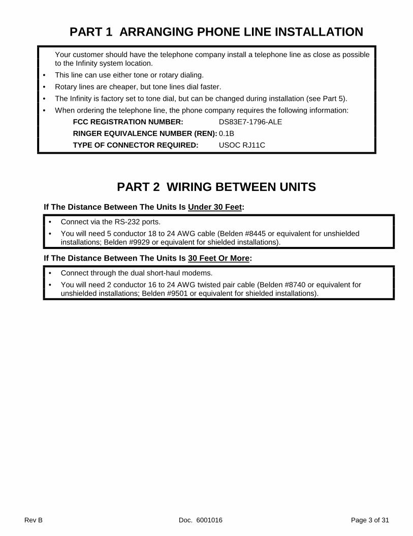
PART 1 ARRANGING PHONE LINE INSTALLATION
Your customer should have the telephone company install a telephone line as close as possibleto the Infinity system location.
• This line can use either tone or rotary dialing.
• Rotary lines are cheaper, but tone lines dial faster.
• The Infinity is factory set to tone dial, but can be changed during installation (see Part 5).
• When ordering the telephone line, the phone company requires the following information:
FCC REGISTRATION NUMBER: DS83E7-1796-ALE
RINGER EQUIVALENCE NUMBER (REN): 0.1B
TYPE OF CONNECTOR REQUIRED: USOC RJ11C
PART 2 WIRING BETWEEN UNITS
If The Distance Between The Units Is Under 30 Feet:
• Connect via the RS-232 ports.
• You will need 5 conductor 18 to 24 AWG cable (Belden #8445 or equivalent for unshieldedinstallations; Belden #9929 or equivalent for shielded installations).
If The Distance Between The Units Is 30 Feet Or More:
• Connect through the dual short-haul modems.
• You will need 2 conductor 16 to 24 AWG twisted pair cable (Belden #8740 or equivalent forunshielded installations; Belden #9501 or equivalent for shielded installations).
Page 4 of 31 Doc. 6001016 Rev B
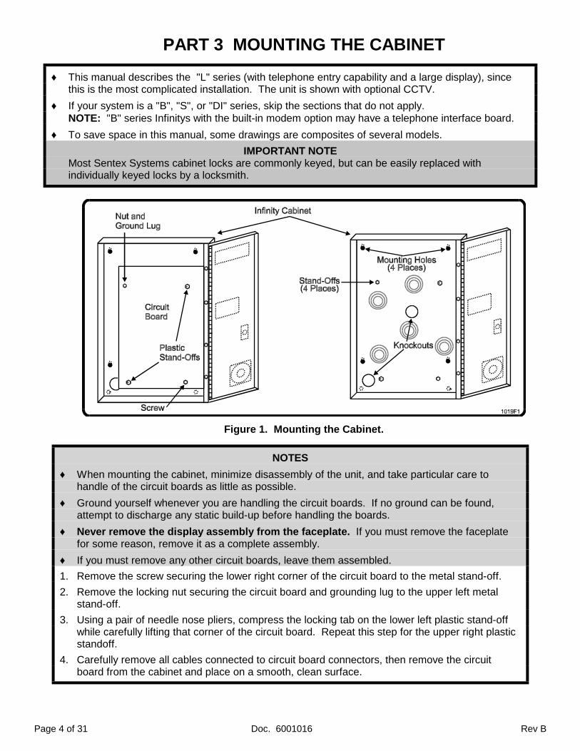
PART 3 MOUNTING THE CABINET
♦ This manual describes the "L" series (with telephone entry capability and a large display), sincethis is the most complicated installation. The unit is shown with optional CCTV.
♦ If your system is a "B", "S", or "DI" series, skip the sections that do not apply.NOTE: "B" series Infinitys with the built-in modem option may have a telephone interface board.
♦ To save space in this manual, some drawings are composites of several models.
IMPORTANT NOTEMost Sentex Systems cabinet locks are commonly keyed, but can be easily replaced withindividually keyed locks by a locksmith.
Figure 1. Mounting the Cabinet.
NOTES
♦ When mounting the cabinet, minimize disassembly of the unit, and take particular care tohandle of the circuit boards as little as possible.
♦ Ground yourself whenever you are handling the circuit boards. If no ground can be found,attempt to discharge any static build-up before handling the boards.
♦ Never remove the display assembly from the faceplate. If you must remove the faceplatefor some reason, remove it as a complete assembly.
♦ If you must remove any other circuit boards, leave them assembled.
1. Remove the screw securing the lower right corner of the circuit board to the metal stand-off.
2. Remove the locking nut securing the circuit board and grounding lug to the upper left metalstand-off.
3. Using a pair of needle nose pliers, compress the locking tab on the lower left plastic stand-offwhile carefully lifting that corner of the circuit board. Repeat this step for the upper right plasticstandoff.
4. Carefully remove all cables connected to circuit board connectors, then remove the circuitboard from the cabinet and place on a smooth, clean surface.
Rev B Doc. 6001016 Page 5 of 31
5. For wall mount: Remove the bottom left knockout from the back of the cabinet.For pedestal mount: Remove the center knockout from the back of the cabinet.To enter the cabinet elsewhere, drill a hole through the cabinet and make sure you carefullyremove all debris.
6. Install the top two screws or bolts in the wall, pedestal, etc., but leave them loose. Hang thecabinet on them, then install the screws/bolts in the bottom two openings. Securely tighten allfour screws/bolts.
7. GROUND THE CABINET AND CIRCUIT BOARD THOROUGHLY to a good earth/cold waterground using the solder lug on the upper left circuit board standoff.
8. Pull all wires into the cabinet and dress to the left side.NOTE: If unit has optional CCTV, dress the coaxial cable and CCTV power wire to right.
9. Remount the circuit board by carefully aligning the stand-off holes with the plastic stand-offsand pressing down until the stand-off tabs lock.
10. Replace the screw securing the lower right corner of the circuit board to the metal stand-off.
11. Replace the locking nut securing the circuit board and grounding lug to the upper left metalstand-off.
12. Carefully reconnect all circuit board cables that were disconnected before.
IMPORTANT NOTICE
Infinity "L" series systems exposed to temperatures above 80 degrees F and/or direct sunlightfor extended periods require the internal cooling fan option to prevent temporary "blotching" ofthe display. Even with this option installed, mounting the unit in the shade will help maintainoptimum display readability.

Page 6 of 31 Doc. 6001016 Rev B
PART 4 WIRINGA. TELEPHONE INTERFACE BOARD CONNECTIONS
Figure 2. Telephone Interface Board Connections.
1. Connect a two conductor, 18 to 22 AWG cable (Belden Datalene #9501 or equivalent) to TB1on the right lower corner of the telephone interface board (see Figure 2).
2. Connect the other end of this cable to the "tip" and "ring" terminals on the telephone companyjack (polarity is unimportant).
• The remaining terminals of TB1 are for the handset on Handset models and are not used onHands-Free models.

Rev B Doc. 6001016 Page 7 of 31
B. PROCESSOR BOARD SIGNAL CONNECTIONS
Figure 3. Infinity Circuit Board Connections.

Page 8 of 31 Doc. 6001016 Rev B
Refer to Figure 3 and connect the wires from Infinity-controlled devices as follows:! Relay/door 1 .....TB 9! Relay/door 2 .....TB 10! Relay 3 .............TB 11! Relay 4 .............TB 12
Which terminals are used depends on the type of device being controlled:
♦ Dry Contact Closures (most gate operators): Connect wires to NO and COMMON terminals.
♦ Normally Locked Strikes: Connect one wire from the strike power supply to the NO terminaland one wire from the door strike to COMMON on the same terminal block. Connect theremaining wires from each source off the board with a wire nut.
♦ Magnetic Locks and Normally Unlocked Strikes: Connect one wire from the power supplyto the NC terminal and one wire from the door strike to COMMON on the same terminal block.Connect the remaining wires from each source off the board with a wire nut.
CAUTIONMagnetic locks and DC powered strikes produce potentially damaging voltage spikes. Sentexstrongly recommends installing an IN4001 diode across the magnetic lock coil with the cathode(the banded end) connected to the positive side of the coil, and the anode connected to thenegative side of the coil.
C. OPTIONAL CLOSED CIRCUIT TELEVISION CONNECTIONS
Figure 4. Optional CCTV Unit.
NOTE: You will need a monitor, or a television with special monitor equipment to see the pictureprovided by the Closed-Circuit Television.
1. Connect a two-conductor 10 to 18 AWG cable (Belden Datalene #9501 or equivalent) to TB1 on theright lower corner of the CCTV Power Supply Board.
2. Connect coaxial cable with BNC connectors (Belden #9240 or equivalent) to right angle BNCconnector at J2, on the middle bottom of the CCTV Power Supply Board.
Rev B Doc. 6001016 Page 9 of 31
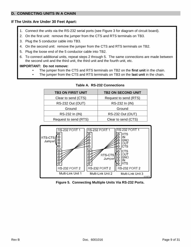
D. CONNECTING UNITS IN A CHAIN
If The Units Are Under 30 Feet Apart:
1. Connect the units via the RS-232 serial ports (see Figure 3 for diagram of circuit board).
2. On the first unit: remove the jumper from the CTS and RTS terminals on TB3.
3. Plug the 5 conductor cable into TB3.
4. On the second unit: remove the jumper from the CTS and RTS terminals on TB2.
5. Plug the loose end of the 5 conductor cable into TB2.
6. To connect additional units, repeat steps 2 through 5. The same connections are made betweenthe second unit and the third unit, the third unit and the fourth unit, etc.
IMPORTANT: Do not remove:• The jumper from the CTS and RTS terminals on TB2 on the first unit in the chain.• The jumper from the CTS and RTS terminals on TB3 on the last unit in the chain.
Table A. RS-232 Connections
TB3 ON FIRST UNIT TB2 ON SECOND UNIT
Clear to send (CTS) Request to send (RTS)
RS-232 Out (OUT) RS-232 In (IN)
Ground Ground
RS-232 In (IN) RS-232 Out (OUT)
Request to send (RTS) Clear to send (CTS)
Figure 5. Connecting Multiple Units Via RS-232 Ports.

Page 10 of 31 Doc. 6001016 Rev B
If The Units Are 30 Or More Feet Apart:
An internal 300 baud modem is standard in all except the “B” series (where it is an option). Connectthe units through the dual short-haul modems (See Figure 6).1. On the first unit, insert the 2 conductor cable into the LINE 2 plug and tighten the screws
securely. It does not matter which wire is inserted into which opening of the plug (See Figure 7).2. On the second unit, insert the the loose end of the 2 conductor cable into the LINE 1 plug and
tighten the screws securely (See Figure 7).3. To connect additional units, repeat steps 2 and 3. The same connections are made between the
second unit and the third unit, the third unit and the fourth unit, etc.
Figure 6. Connecting Multiple Units Through Short-Haul Modems.
Figure 7. Dual Short-Haul Modem.
Rev B Doc. 6001016 Page 11 of 31
E. INSTALLING A NEW UNIT IN AN EXISTING MULTI-LINK CHAIN
1. Once the unit is installed, resequence all the units in the chain.
2. Enter the system’s configuration information into the new unit, (i.e., program access codes,relay activation times, holiday schedules, etc.).
3. If you are using SPS or SPSWin:
A. Perform Receive All from the new unit’s memory.
B. Copy the system’s memory.
C. Enter the system’s configuration into SPS or SPSWin.
D. Send the new configuration to the new unit.

Page 12 of 31 Doc. 6001016 Rev B
F. POWER CONNECTIONS
The Infinity system can operate on either AC or DC power.
AC POWER
Connect one end of a two conductor stranded wire cable to TB 1 on the main processor board(see Figure 3) and the other end to the transformer provided with the system. Then plug thetransformer into a 120 VAC outlet.
NOTES:
1. Line Loss: If system and power supply are too far apart, line loss may result in inadequatevoltage being delivered to the system. Refer to Table 1 (below) for wire sizes and distances.
2. Dedicated Power Source: Wire each outlet used by an Infinity to its own circuit breaker. Thisreduces line noise and minimizes the risk of other equipment interrupting unit operation.
3. Dedicated Power Supply: The transformer used by the Infinity cannot also provide power to thedoor strikes (if used) or the optional CCTV.
DC POWER
Connect one end of a two conductor stranded wire cable to TB 13 (TB1 on E and F rev. boards)on the main processor board (see Figure 3) and the other end to the power supply. Then plugthe power supply into a 120 VAC outlet. Follow the same steps for optional CCTV.
NOTES:
1. DC Power: must be at least 13.5 Volts.2. DC Input Fuse: The DC input on the Infinity board is not fused. The installer must wire a fuse
between the DC power supply and the system during installation.3. Line Loss: If system and power supply are too far apart, line loss may result in inadequate
voltage being delivered to the system. Refer to Table 1 (below) for wire sizes and distances.4. UPS: The Infinity will not trickle charge a battery, so DC power must be supplied by an
uninterruptible power supply.
OPTIONAL CCTV
AC or DC Power: Connect one end of a two conductor stranded wire cable to TB 1 on the mainprocessor board (see Figure 3) and the other end to the transformer provided with the system.Then plug the transformer into a 120 VAC outlet.
NOTES:
1. Line Loss: Refer to Table 2 (below) for wire sizes and distances.
DC POWERWIRE SIZE
DISTANCE AC POWERWIRE SIZE
18 AWG 30' and under 14 AWG16 AWG 30'-75' 12 AWG12 AWG 75'-150' -----10 AWG 150'-250' -----
Table 1 - Power Wire Distance for TIB.
DC POWERWIRE SIZE
DISTANCE AC POWERWIRE SIZE
18 AWG 30' and under 18 AWG18 AWG 30’ – 75’ 18 AWG18 AWG 75’ – 150‘ 14 AWG16 AWG 150’ – 250’ 12 AWG12 AWG 250’ – 500’ 10 AWG
Table 2 – Power Wire Distance for CCTV.

Rev B Doc. 6001016 Page 13 of 31
G. POWER ON
MAIN PROCESSOR BOARD
The Infinity main processor board has a power monitor that indicates if proper voltage is available.It has two red LEDs labeled HI and LO, one green LED labeled IN, and a MONITOR CLEARbutton, all located in the upper right corner of the main processor board (see Figure 3). If inputpower is not in the acceptable range, the HI or LO LEDs light and remain lit until the MONITORCLEAR button is pressed. This allows continuous power monitoring and captures any transients.
Check voltage using the power monitor as follows:
1. Apply power to the board. The IN and LO LEDs will light.
2. Press the MONITOR CLEAR button located next to the LEDs.
♦ If the IN LED lights, proper voltage is being provided.
♦ If the LO LED lights, the voltage is too low. Check the power connections, wiring, andtransformer.
♦ If the HI LED lights, the voltage is too high. Check the power connections, wiring, andtransformer.
CCTV POWER SUPPLY BOARD
Power comes on when the transformer or power supply is plugged in. There are no powerindicators on the board.
Page 14 of 31 Doc. 6001016 Rev B
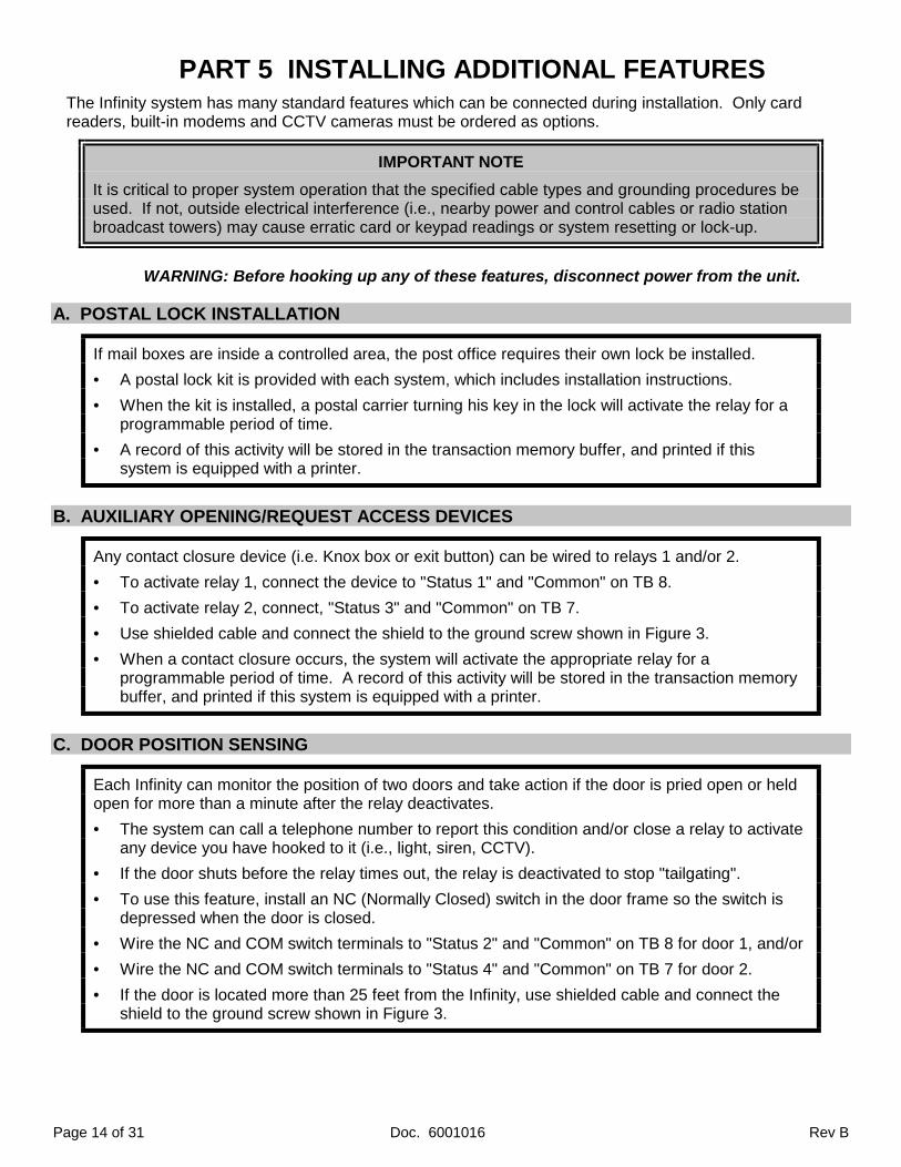
PART 5 INSTALLING ADDITIONAL FEATURESThe Infinity system has many standard features which can be connected during installation. Only cardreaders, built-in modems and CCTV cameras must be ordered as options.
IMPORTANT NOTE
It is critical to proper system operation that the specified cable types and grounding procedures beused. If not, outside electrical interference (i.e., nearby power and control cables or radio stationbroadcast towers) may cause erratic card or keypad readings or system resetting or lock-up.
WARNING: Before hooking up any of these features, disconnect power from the unit.
A. POSTAL LOCK INSTALLATION
If mail boxes are inside a controlled area, the post office requires their own lock be installed.
• A postal lock kit is provided with each system, which includes installation instructions.
• When the kit is installed, a postal carrier turning his key in the lock will activate the relay for aprogrammable period of time.
• A record of this activity will be stored in the transaction memory buffer, and printed if thissystem is equipped with a printer.
B. AUXILIARY OPENING/REQUEST ACCESS DEVICES
Any contact closure device (i.e. Knox box or exit button) can be wired to relays 1 and/or 2.
• To activate relay 1, connect the device to "Status 1" and "Common" on TB 8.
• To activate relay 2, connect, "Status 3" and "Common" on TB 7.
• Use shielded cable and connect the shield to the ground screw shown in Figure 3.
• When a contact closure occurs, the system will activate the appropriate relay for aprogrammable period of time. A record of this activity will be stored in the transaction memorybuffer, and printed if this system is equipped with a printer.
C. DOOR POSITION SENSING
Each Infinity can monitor the position of two doors and take action if the door is pried open or heldopen for more than a minute after the relay deactivates.
• The system can call a telephone number to report this condition and/or close a relay to activateany device you have hooked to it (i.e., light, siren, CCTV).
• If the door shuts before the relay times out, the relay is deactivated to stop "tailgating".
• To use this feature, install an NC (Normally Closed) switch in the door frame so the switch isdepressed when the door is closed.
• Wire the NC and COM switch terminals to "Status 2" and "Common" on TB 8 for door 1, and/or
• Wire the NC and COM switch terminals to "Status 4" and "Common" on TB 7 for door 2.
• If the door is located more than 25 feet from the Infinity, use shielded cable and connect theshield to the ground screw shown in Figure 3.
Rev B Doc. 6001016 Page 15 of 31
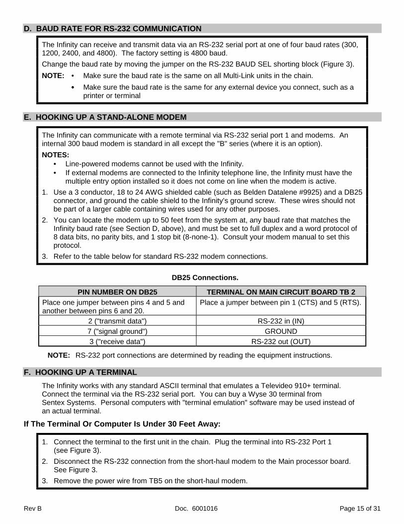
D. BAUD RATE FOR RS-232 COMMUNICATION
The Infinity can receive and transmit data via an RS-232 serial port at one of four baud rates (300,1200, 2400, and 4800). The factory setting is 4800 baud.
Change the baud rate by moving the jumper on the RS-232 BAUD SEL shorting block (Figure 3).
NOTE: • Make sure the baud rate is the same on all Multi-Link units in the chain.
•••• Make sure the baud rate is the same for any external device you connect, such as aprinter or terminal
E. HOOKING UP A STAND-ALONE MODEM
The Infinity can communicate with a remote terminal via RS-232 serial port 1 and modems. Aninternal 300 baud modem is standard in all except the "B" series (where it is an option).
NOTES:• Line-powered modems cannot be used with the Infinity.• If external modems are connected to the Infinity telephone line, the Infinity must have the
multiple entry option installed so it does not come on line when the modem is active.
1. Use a 3 conductor, 18 to 24 AWG shielded cable (such as Belden Datalene #9925) and a DB25connector, and ground the cable shield to the Infinity’s ground screw. These wires should notbe part of a larger cable containing wires used for any other purposes.
2. You can locate the modem up to 50 feet from the system at, any baud rate that matches theInfinity baud rate (see Section D, above), and must be set to full duplex and a word protocol of8 data bits, no parity bits, and 1 stop bit (8-none-1). Consult your modem manual to set thisprotocol.
3. Refer to the table below for standard RS-232 modem connections.
DB25 Connections.
PIN NUMBER ON DB25 TERMINAL ON MAIN CIRCUIT BOARD TB 2
Place one jumper between pins 4 and 5 andanother between pins 6 and 20.
Place a jumper between pin 1 (CTS) and 5 (RTS).
2 ("transmit data") RS-232 in (IN)
7 ("signal ground") GROUND
3 ("receive data") RS-232 out (OUT)
NOTE: RS-232 port connections are determined by reading the equipment instructions.
F. HOOKING UP A TERMINAL
The Infinity works with any standard ASCII terminal that emulates a Televideo 910+ terminal.Connect the terminal via the RS-232 serial port. You can buy a Wyse 30 terminal fromSentex Systems. Personal computers with "terminal emulation" software may be used instead ofan actual terminal.
If The Terminal Or Computer Is Under 30 Feet Away:
1. Connect the terminal to the first unit in the chain. Plug the terminal into RS-232 Port 1(see Figure 3).
2. Disconnect the RS-232 connection from the short-haul modem to the Main processor board.See Figure 3.
3. Remove the power wire from TB5 on the short-haul modem.

Page 16 of 31 Doc. 6001016 Rev B
4. Remove the other end of the power wire from TB5 on the main processor board.NOTE: Do not use either of these terminal blocks for any other purpose.
5. Use a 3 conductor, 18 to 24 AWG shielded cable (such as Belden Datalene #9925). Theseconductors should not be part of a larger cable that contains wires used for other purposes.
6. Use a DB25 male connector (DB9 if your computer has a 9-pin serial port), and ground thecable shield at Infinity's ground screw.
7. Your terminal must be running at the same baud rate as the Infinity (see step D, above), andmust be set to full duplex communications and a word protocol of 8 data bits, no parity bits, and1 stop bit (8-none-1). Consult your terminal's manual to determine how to set this protocol.The connections for the video terminal or computer are shown below:
DB25 Connections.
PIN NUMBER ON DB 25 TERMINAL ON MAIN CIRCUIT BOARD TB 2
Place one jumper between pins 4 and 5 andanother between pins 6 and 20.
Place a jumper between pins 1 ("cts") and 5 ("rts").
3 ("receive data") RS-232 out ("out")
7 ("signal ground") GROUND
2 ("transmit data") RS-232 in ("in")
DB9 Connections.
PIN NUMBER ON DB 25 TERMINAL ON MAIN CIRCUIT BOARD TB 2
Place one jumper between pins 4 and 6 andanother between pins 7 and 8.
Place a jumper between pins 1 ("cts") and 5 ("rts").
2 ("receive data") RS-232 out ("out")
5 ("signal ground") GROUND
3 ("transmit data") RS-232 in ("in")
Figure 8. Direct Connection Between Computer and Unit 1 of Multi-Link Chain.

Rev B Doc. 6001016 Page 17 of 31
If The Computer or Terminal Is 30 Or More Feet Away:
1. Connect the terminal’s or computer’s modem to the first unit in the chain.
2. If you are using a terminal or a computer with an external modem, connect the modem to theterminal or computer (see terminal, computer and/or modem instructions).
3. Connect the modem to the first Infinity in the chain using 2 conductor, 16 to 24 AWGunshielded telephone wire.
4. Plug one end of the wire into the terminal or computer modem plug marked “LINE”.
5. Connect the other wire end to “LINE 1” on the modem in the first Infinity unit in the chain.
6. The terminal or computer must be running at the same baud rate as the Infinity (see Section D,above) and must be set to full duplex communications with a word protocol of 8 data bits, noparity bits, and 1 stop bit (8-none-1). Consult your terminal's manual to to set this protocol.Connections for the video terminal or computer are shown in Figure 9, below:
Figure 9. PC/Terminal Connected to First Infinity in a Chain Via Stand Alone Modem.
G. HOOKING UP A PRINTER
Connect standard PC printers to the Infinity via RS-232 serial interface as follows:
1. On the last Infinity unit in the chain, connect a serial printer cable no longer than 30 feet to RS-232 Port 2 on the main processor board. Connect a jumper from pin 1 (CTS) to pin 2 (RTS).
2. You can connect your own serial printer to RS-232 Port 2 of the last unit in the chain using a 3conductor, 18 AWG shielded cable and the appropriate DB-type connector.
NOTES:
" Printers must be connected to the last Infinity unit in the chain.
" Run printer wires in their own metal conduit to reduce interference and electrical noise.
" Serial printers must have the same baud rate as the Infinity, and must be set to FDX (fullduplex), 8 data bits, no parity bits, and 1 stop bit (8-N-1). Refer to your printer manual.
" Parallel printers may be connected to the "AUX" or printer port of a PC or terminal with astandard Centronics parallel printer cable.
" Okidata 184 Turbo RS-232 serial printers are available from Sentex, and come with a DB25(25-pin data connector) and cabling.
Page 18 of 31 Doc. 6001016 Rev B
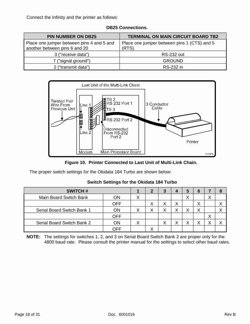
Connect the Infinity and the printer as follows:
DB25 Connections.
PIN NUMBER ON DB25 TERMINAL ON MAIN CIRCUIT BOARD TB2
Place one jumper between pins 4 and 5 andanother between pins 6 and 20
Place one jumper between pins 1 (CTS) and 5(RTS).
3 ("receive data") RS-232 out
7 ("signal ground") GROUND
2 (“transmit data”) RS-232 in
Figure 10. Printer Connected to Last Unit of Multi-Link Chain.
The proper switch settings for the Okidata 184 Turbo are shown below:
Switch Settings for the Okidata 184 Turbo
SWITCH # 1 2 3 4 5 6 7 8
Main Board Switch Bank ON X X X
OFF X X X X X
Serial Board Switch Bank 1 ON X X X X X X X
OFF X
Serial Board Switch Bank 2 ON X X X X X X X
OFF X
NOTE: The settings for switches 1, 2, and 3 on Serial Board Switch Bank 2 are proper only for the4800 baud rate. Please consult the printer manual for the settings to select other baud rates.
Rev B Doc. 6001016 Page 19 of 31
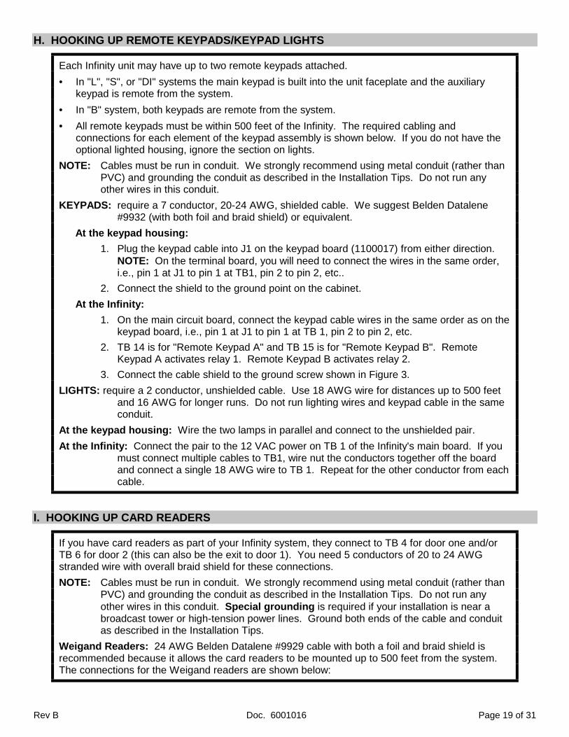
H. HOOKING UP REMOTE KEYPADS/KEYPAD LIGHTS
Each Infinity unit may have up to two remote keypads attached.
• In "L", "S", or "DI" systems the main keypad is built into the unit faceplate and the auxiliarykeypad is remote from the system.
• In "B" system, both keypads are remote from the system.
• All remote keypads must be within 500 feet of the Infinity. The required cabling andconnections for each element of the keypad assembly is shown below. If you do not have theoptional lighted housing, ignore the section on lights.
NOTE: Cables must be run in conduit. We strongly recommend using metal conduit (rather thanPVC) and grounding the conduit as described in the Installation Tips. Do not run anyother wires in this conduit.
KEYPADS: require a 7 conductor, 20-24 AWG, shielded cable. We suggest Belden Datalene#9932 (with both foil and braid shield) or equivalent.
At the keypad housing:
1. Plug the keypad cable into J1 on the keypad board (1100017) from either direction.NOTE: On the terminal board, you will need to connect the wires in the same order,i.e., pin 1 at J1 to pin 1 at TB1, pin 2 to pin 2, etc..
2. Connect the shield to the ground point on the cabinet.
At the Infinity:
1. On the main circuit board, connect the keypad cable wires in the same order as on thekeypad board, i.e., pin 1 at J1 to pin 1 at TB 1, pin 2 to pin 2, etc.
2. TB 14 is for "Remote Keypad A" and TB 15 is for "Remote Keypad B". RemoteKeypad A activates relay 1. Remote Keypad B activates relay 2.
3. Connect the cable shield to the ground screw shown in Figure 3.
LIGHTS: require a 2 conductor, unshielded cable. Use 18 AWG wire for distances up to 500 feetand 16 AWG for longer runs. Do not run lighting wires and keypad cable in the sameconduit.
At the keypad housing: Wire the two lamps in parallel and connect to the unshielded pair.
At the Infinity: Connect the pair to the 12 VAC power on TB 1 of the Infinity's main board. If youmust connect multiple cables to TB1, wire nut the conductors together off the boardand connect a single 18 AWG wire to TB 1. Repeat for the other conductor from eachcable.
I. HOOKING UP CARD READERS
If you have card readers as part of your Infinity system, they connect to TB 4 for door one and/orTB 6 for door 2 (this can also be the exit to door 1). You need 5 conductors of 20 to 24 AWGstranded wire with overall braid shield for these connections.
NOTE: Cables must be run in conduit. We strongly recommend using metal conduit (rather than PVC) and grounding the conduit as described in the Installation Tips. Do not run any other wires in this conduit. Special grounding is required if your installation is near a broadcast tower or high-tension power lines. Ground both ends of the cable and conduit as described in the Installation Tips.
Weigand Readers: 24 AWG Belden Datalene #9929 cable with both a foil and braid shield isrecommended because it allows the card readers to be mounted up to 500 feet from the system.The connections for the Weigand readers are shown below:

Page 20 of 31 Doc. 6001016 Rev B
Weigand Reader Connections
READER WIRE COLOR CONDUCTS MAIN BOARD TB 4 OR TB 6 TERMINAL
BROWN LED/GROUND LED A (LED B ON TB5)
WHITE DATA 1 A (OR B) READER 1
GREEN DATA 0 A (OR B) READER 0
RED +5 VDC +5 VDC
BLACK GROUND GROUND
CABLE SHIELDS GROUND CHASSIS (Ground Lug)
BLUE --- NOT USED
Barium Ferrite Readers: Use the same type of cable as the Weigand installation if the readersare within 125 feet of the Infinity. If the cable run is longer, use 20 AWG wire for up to 350 feet and18 AWG wire for up to 500 feet. Barium Ferrite reader connections are similar to Weigand readerconnections except for requiring +12 VDC. Connect the red wire from each reader to a +12 VDCterminal on TB 5 instead of a +5 VDC terminal on TB 4 or TB 6 (see chart below).
Barium Ferrite and Proximity Card Reader Connections
READER WIRE COLOR CONDUCTS MAIN BOARD TB 4 OR TB 6 TERMINAL
BROWN LED/GROUND LED A (OR LED B ON TB5)
WHITE DATA 1 A (OR B) READER 1
GREEN DATA 0 A (OR B) READER 0
RED +12 VDC MAIN PROCESSOR BOARD TERMINAL TB5
BLACK GROUND GROUND
Proximity Card Readers: 24 AWG Belden Datalene #9929 cable with both a foil and braid shieldis recommended because it allows the card readers to be mounted up to 500 feet from the system.The connections for the Proximity card readers are the same as the Barium Ferrite readers. Theconnections for the proximity card readers are shown in the chart above:
ClikCard Receivers: 24 AWG Belden Datalene #9929 cable with both a foil and braid shield isrecommended because it allows the ClikCard readers to be mounted up to 500 feet from thesystem. The connection for the ClikCard receivers are as follows:
ClikCard Receiver Connections
READER WIRE COLOR CONDUCTS MAIN BOARD TB 4 OR TB 6 TERMINAL
BROWN LED/GROUND LED A (OR LED B ON TB5)
WHITE DATA 1 A (OR B) READER 1
GREEN DATA 0 A (OR B) READER 0
RED VCC LC RECEIVER: +5 VDCNARROW BAND RECEIVER: +12VDC (ON TB5)
BLACK GROUND GROUND

Rev B Doc. 6001016 Page 21 of 31
J. HOOKING UP BUILT-IN MODEM/REMOTE PROGRAMMING/MULTIPLE ENTRY
These options require no special installation. However, if you intend to program the systems viamodem, multiple systems cannot use the same telephone line. If two systems are connected to thesame telephone line, they will create a communication problem for the sending modem.
K. HOOKING UP OPTIONAL CCTV
1. Plug the loose end of the coaxial cable into the monitor or television.NOTE: Maximum length of coaxial cable must not exceed 100 feet.
2. When the monitor or television is turned on, picture will appear.

Page 22 of 31 Doc. 6001016 Rev B
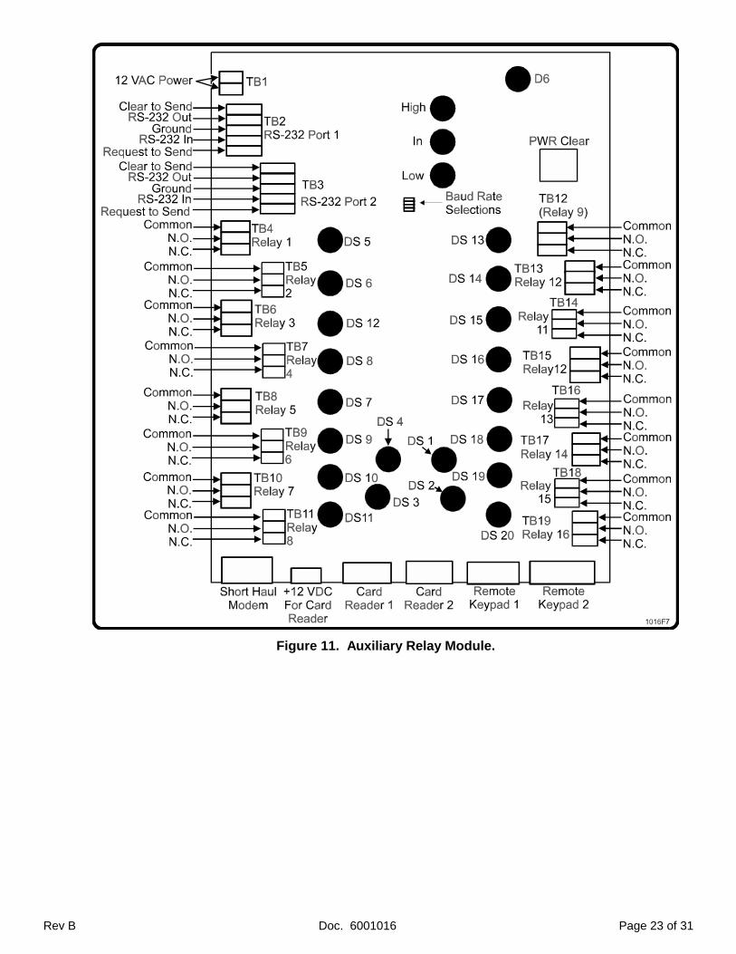
PART 6 INSTALLING THE AUXILIARY RELAY MODULEYou can purchase an Auxiliary Relay Module (ARM) with a Multi-Link system. The ARM unit gives youtimed activation for up to sixteen relays. You can use the ARM unit for such things as:
• Elevator access control
• Turning on and off heating and air conditioning systems
• Controlling a gate operator
Installation of the ARM unit is the same as the installation of the Infinity “B” unit, with the followingexceptions:
♦ The ARM unit cannot be the first unit in a Multi-Link chain.
♦ You may program the relays on the ARM unit to be either energized or de-energized at power up.If you program the relay to be energized when power is applied and power is lost, the relay willswitch states.
Example 1: You connect an elevator to relay 1 and program it to be energized at power up. Ifpower to the ARM unit is lost, the elevators will continue to operate.
Example 2: You connect a gate operator to relay 2 and program it to be de-energized at powerup. If power to the ARM unit is lost, the gate will remain closed.
♦ Keypads and card readers are not automatically connected to specific relays. You must programeach keypad and card reader to activate a specific relay. For instructions, please refer toProgramming Infinity Systems with Multi-Link Firmware, Document Number 6001014.
1. When attaching devices to the relays, refer to the device specifications for size and length of cable.
♦ If the relay is programmed to be energized at power up, (e.g., elevator control panel orHVAC):
A. Attach one wire to the NC terminal of the relay.
B. Attach the other wire to the COMMON terminal of the same relay.
♦ If the relay is programmed to be de-energized at power up, (e.g., door or gate operator):
A. Attach one wire to the NO terminal of the relay.
B. Attach the other wire to the COMMON terminal on the same relay.
2. If the ARM unit is the last unit in the Multi-Link chain:
A. Disconnect TB3 RS-232 Port 2 on the main processor board from TB4 RS-232 Port 2 on theshort-haul modem board.
B. Place a jumpter between the CTS and RTS terminal on TB3 RS-232 Port 2 on the mainprocessor board.
3. Once the ARM unit is installed and tested, you will need to program the state of the relays at powerup. For instructions, please refer to Programming Infinity Systems with Multi-Link Firmware,Document Number 6001014.
Rev B Doc. 6001016 Page 23 of 31
Figure 11. Auxiliary Relay Module.
Page 24 of 31 Doc. 6001016 Rev B
PART 7 TESTING AND ADJUSTING THE UNITSWhen connections have been completed, the system should be put through a functional test. The testsequence depends on the series system and options used. Before testing the unit, be sure to read theaccompanying manual, Programming Infinity Systems with Multi-Link Firmware (Doc. No. 6001014).
First, you must sequence the units in the chain. Next, you can perform functional testing, i.e., programthe units with some test codes, cards, telephone numbers, etc., then use these entries to test all relays,card readers and auxiliary keypads. Be sure to test each unit in the chain. The various function testsare described below.
A. SEQUENCE THE UNITS IN THE CHAIN
Performing this step causes each unit to identify its position in the chain, determines how many unitsthere are in the chain, and records each individual unit’s number and serial number. These instructionsare explained fully in the Programming Infinity Systems with Multi-Link Firmware (Doc. No. 6001014).
IMPORTANT NOTE:
If sequencing is done via modem, make sure only the first unit in the chain is connected to thetelephone line when you call. Until the initial sequencing is done, each unit will respond as if it is unit“1”. Once the units are resequenced, multiple units can be connected to the same line since onlyunit “1” will answer the line.
♦ Select programming area “80” and press ENTER at the prompt. The sequencing process may takea few moments. The units, their numbers in the chain, and their serial numbers will be displayed.
B. LCD DISPLAY/FAN OPTION
LCD Display: Observe the viewing angle and contrast, and adjust if necessary using the"CONTRAST ADJUSTMENT" pot on the main processor board (see Figure 3). The letters aredarkest when properly adjusted. Be sure to adjust the pot in both directions to find the maximumcontrast.
1. Adjust the contrast for someone 5 feet 6 inches tall, standing 2 feet away from the Infinity.For drive-up applications, assume that person is sitting in a midsized car.
2. Adjust the viewing angle so the display is visible 8 to 10 inches higher and lower.
3. Adjust display so the background is yellow (white on older models) and the lettering is blue.
Internal Fan Option: Fans prevent display "blotching" and uneven coloration for installations indirect sunlight and very high temperatures (this harmless, temporary phenomenon disappearswhen the temperature drops). If included, the fans will be mounted inside the enclosure on bothsides of the display. Ensure the fans operate properly before completing your installation.
1. Ensure that fans are plugged into the two pin headers marked "FAN A" (J16) and"FAN B" (J17) at the top of the board (with the red wire on the + terminal).
2. Ensure the thermistor mounted to the bracket below the display is plugged into the two pinheader at the bottom of the board marked "TEMP SENSE" (J9).
3. Ensure there is nothing obstructing the air passage through the bracket assembly surroundingthe display.
NOTE: Fans only operate above 75-85O F, and so may not operate even when plugged in.
Rev B Doc. 6001016 Page 25 of 31
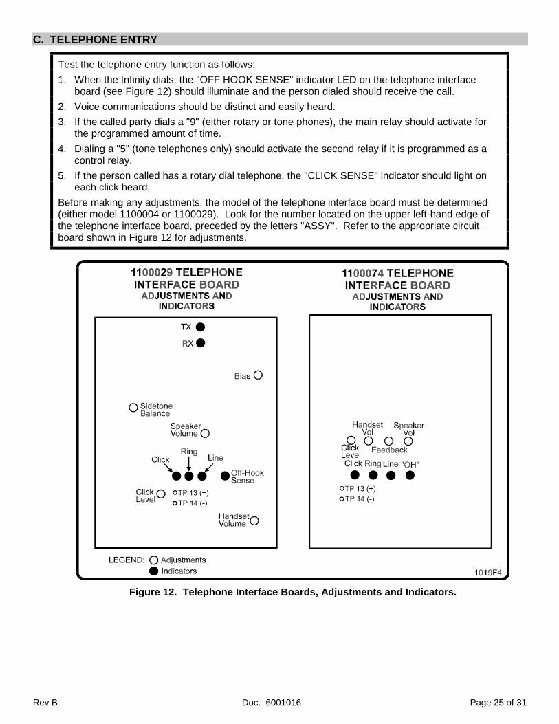
C. TELEPHONE ENTRY
Test the telephone entry function as follows:
1. When the Infinity dials, the "OFF HOOK SENSE" indicator LED on the telephone interfaceboard (see Figure 12) should illuminate and the person dialed should receive the call.
2. Voice communications should be distinct and easily heard.
3. If the called party dials a "9" (either rotary or tone phones), the main relay should activate forthe programmed amount of time.
4. Dialing a "5" (tone telephones only) should activate the second relay if it is programmed as acontrol relay.
5. If the person called has a rotary dial telephone, the "CLICK SENSE" indicator should light oneach click heard.
Before making any adjustments, the model of the telephone interface board must be determined(either model 1100004 or 1100029). Look for the number located on the upper left-hand edge ofthe telephone interface board, preceded by the letters "ASSY". Refer to the appropriate circuitboard shown in Figure 12 for adjustments.
Figure 12. Telephone Interface Boards, Adjustments and Indicators.

Page 26 of 31 Doc. 6001016 Rev B
1. MODEL 1100029 TELEPHONE INTERFACE BOARD ADJUSTMENTS
All adjustments must be made in the following order:
SIDETONE BALANCE: The sidetone balance must be set correctly for other adjustments to work.
1. Locate TP 13 and TP 14 to the right of the "CLICK LEVEL" pot (see Figure 12).
2. Connect the positive lead of a voltmeter to TP 13 and the negative lead to TP 14. Analogmeters work best, but digital meters may be used if the pot is adjusted very slowly.
3. Enter the programming mode by pressing the "✱ " key and your six digit access code.
4. When the menu prompt is displayed, enter "69" and the "#" key.
5. A continuous tone will sound from the headset or speaker. Adjust the "SIDETONEBALANCE" pot until the meter is at its lowest reading. If the tone ends before you completethis adjustment, repeat steps 4 and 5.
INSUFFICIENT VOLUME: The volume may be raised or lowered by adjusting the "HANDSETVOLUME" pot (handset models) or the "SPEAKER VOLUME" pot (hands-free models).
CLICK LEVEL: Adjust the click level as follows:
1. Set the "CLICK LEVEL" pot (see Figure 12) to the center of its range.
2. Enter a directory code of a tenant with a rotary-dial telephone.
2. When they answer, ask them to dial a "9". The "CLICK" LED should flash until the strikerelay opens the door and the board emits a click.
3. If the relay doesn't click and the "CLICK" LED doesn't flash regularly, turn the "CLICKLEVEL" pot clockwise and repeat steps 2 and 3 until both responses are received.
4. If the relay clicks and the "CLICK" LED stays on or doesn't flash regularly, turn the "CLICKLEVEL" pot counter-clockwise and repeat steps 2 and 3 until both responses are received.
VOICES CUTTING OUT OR CLIPPING: Installation site acoustics may cause "clipping" or"cutting out" of either the visitor's or the tenant's voice. Eliminate this problem as follows:
3. If there is any "clipping" or "cutting of words", determine whose voice is being clipped.
4. Turn the "TENANT BIAS" pot (see Figure 12) counter-clockwise if your voice is being clipped,and clockwise if the tenant's voice is being clipped. Adjust and retest until clipping is gone.
5. If clipping of the tenant's voice continues, turn the "SPEAKER VOLUME" pot slightly counter-clockwise and re-test. In some installations, tenant bias cannot be properly adjusted if thespeaker is set too loud. Also, if the unit is installed in a narrow hallway facing a hard wall, thespeaker's voice reflects back, causing the unit to transmit and interrupting the tenant's voice.Sound-proofing and carpeting can help alleviate this problem.
NOTE: It is preferable to adjust the "TENANT BIAS" pot so that while the visitor is speaking, thetenant can also speak and "break in" on the visitor's voice.
Rev B Doc. 6001016 Page 27 of 31
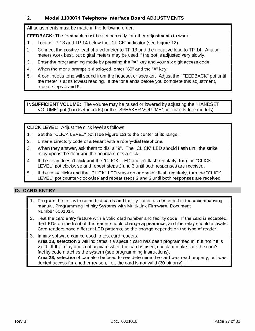
2. Model 1100074 Telephone Interface Board ADJUSTMENTS
All adjustments must be made in the following order:
FEEDBACK: The feedback must be set correctly for other adjustments to work.
1. Locate TP 13 and TP 14 below the "CLICK" indicator (see Figure 12).
2. Connect the positive lead of a voltmeter to TP 13 and the negative lead to TP 14. Analogmeters work best, but digital meters may be used if the pot is adjusted very slowly.
3. Enter the programming mode by pressing the "✱ " key and your six digit access code.
4. When the menu prompt is displayed, enter "69" and the "#" key.
5. A continuous tone will sound from the headset or speaker. Adjust the "FEEDBACK" pot untilthe meter is at its lowest reading. If the tone ends before you complete this adjustment,repeat steps 4 and 5.
INSUFFICIENT VOLUME: The volume may be raised or lowered by adjusting the "HANDSETVOLUME" pot (handset models) or the "SPEAKER VOLUME" pot (hands-free models).
CLICK LEVEL: Adjust the click level as follows:
1. Set the "CLICK LEVEL" pot (see Figure 12) to the center of its range.
2. Enter a directory code of a tenant with a rotary-dial telephone.
3. When they answer, ask them to dial a "9". The "CLICK" LED should flash until the strikerelay opens the door and the boarda emits a click.
4. If the relay doesn't click and the "CLICK" LED doesn't flash regularly, turn the "CLICKLEVEL" pot clockwise and repeat steps 2 and 3 until both responses are received.
5. If the relay clicks and the "CLICK" LED stays on or doesn't flash regularly, turn the "CLICKLEVEL" pot counter-clockwise and repeat steps 2 and 3 until both responses are received.
D. CARD ENTRY
1. Program the unit with some test cards and facility codes as described in the accompanyingmanual, Programming Infinity Systems with Multi-Link Firmware, DocumentNumber 6001014.
2. Test the card entry feature with a volid card number and facility code. If the card is accepted,the LEDs on the front of the reader should change appearance, and the relay should activate.Card readers have different LED patterns, so the change depends on the type of reader.
3. Infinity software can be used to test card readers.Area 23, selection 3 will indicates if a specific card has been programmed in, but not if it isvalid. If the relay does not activate when the card is used, check to make sure the card'sfacility code matches the system (see programming instructions).Area 23, selection 4 can also be used to see determine the card was read properly, but wasdenied access for another reason, i.e., the card is not valid (30-bit only).

Page 28 of 31 Doc. 6001016 Rev B
E. CODE ENTRY
1. Program the unit with some test codes as described in the accompanying manual,Programming Infinity Systems with Multi-Link Firmware, Document Number 6001014.
2. Test the code entry feature with a valid code. The relay for that keypad should activate whenthe code is entered.
3. Infinity software can be used to test code entry.Area 23, selection 4 (see programming instructions) can be used to determine if the code wasreceived properly, but was denied access for some other reason (for example, the code is outof its time zone).
F. POSTAL LOCK, REQUEST FOR ACCESS, DOOR POSITION MONITORING
♦ Test these features by shorting across the appropriate terminal block pins, then check to makesure the associated relays activate and deactivate properly.
♦ Once your wiring is in place, test the functions again.
G. BUILT-IN MODEM
1. Call the first unit in the chain using a Hayes-compatible modem hooked to a terminal (or PCusing terminal emulation software).
2. If connection is made, the "TRANSMIT MODEM DATA" (TX) and "RECEIVE MODEMDATA" (RX) indicators (see Figure 12) should flash as data is transmitted and received, andyou should be able to access the programming mode described in Section 10 of theprogramming manual.
3. If connection is not made, ensure the the baud rates of both modems match. If you have a1100029 board it must be set to 300, 1200, or 2400 baud to communicate with the Infinitysystem's 300 (or 2400) baud modem.
H. MULTIPLE ENTRY
1. Disconnect the telephone line from the system and try dialing a number. If the system displaysa "LINE IN USE - PLEASE WAIT" message, this feature is working correctly.
2. Reconnect the telephone line and the system should beep and display the message"LINE IS NOW AVAILABLE - PRESS # TO TRY TO CALL AGAIN". Make a call or press the"Σ" button until the welcome message returns.
I. METHOD OF DIALING
1. The Infinity is factory set to use DTMF tone dialing. To change to rotary (also called pulse)dialing, enter the programming mode (see programming manual) and press "55" followed by"ENTER".
2. When the new programming prompt appears on the screen, the change has been made. Tochange the method back to DTMF tones, use the same procedure except substitute "60"for "55".

Rev B Doc. 6001016 Page 29 of 31
J. OPTIONAL CCTV MONITORING
Figure 13. CCTV Power Supply Board J1 Connector.
• When the monitor or television is turned on, picture will appear.
• If no picture appears, check the J1 connector on the CCTV power supply board. Make sure theconnector is firmly attached to the power supply board.

Page 30 of 31 Doc. 6001016 Rev B
FCC REQUIREMENTSINSTALLATIONWhen you are ready to install this system, call your telephone company and give them the following information:
1. The telephone number of the line to which you will connect the system.
2. The FCC registration number for the system, which is DS83E7 - 17196 - ALE.
3. The ringer equivalence number (REN) which is 0.1B.
This system connects to the telephone line by means of a standard jack called the USOC RJ11C. If this type of jackis not available where you want to install the system, you will need to order it from the telephone company.
TYPE OF SERVICEYour Sentex Infinity system is designed to be used on standard-device telephone lines. They should not be used oncoin service or party lines. If you have any questions about your telephone line, such as how may pieces ofequipment you can connect to it, the telephone company will provide this information upon request.
TELEPHONE COMPANY PROCEDURESThe goal of the telephone company is to provide you with the best service it can. In order to do this, it mayoccasionally be necessary for them to make changes in their equipment, operations, or procedures. If thesechanges might affect your service or operation of your equipment, the telephone company will give you notice, inwriting, to allow you to make any changes necessary to maintain uninterrupted service.
IF PROBLEMS ARISEIf any of your telephone equipment is not operating properly, you should immediately remove it from your telephoneline, as it may cause harm to telephone network. If the telephone company notes a problem, they may temporarilydiscontinue service. When practical, they will notify you in advance of this documentation. If advance notice is notfeasible, you will be notified as soon as possible. When you are notified, you will be given the opportunity to correctthe problem and informed of your right to file a complaint with the FCC.
In the event that any repairs are ever needed on your system, they should be performed only by an authorizedrepresentative of Sentex Systems, Inc.
DISCONNECTIONIf you should ever decide to permanently disconnect your Infinity system from its present line, please call thetelephone company and let them know of this change.
RADIO FREQUENCYThis equipment has been tested and found to comply with the limits for a Class B digital device, pursuant to part 15of the FCC Rules. These limits are designed to provide reasonable protection against harmful interference whenthe equipment is operated in a residential environment. This equipment generates, uses, and can radiate radiofrequency energy and, if not installed and used in accordance with the instruction manual, may cause harmfulinterference to radio communications. However, there is no guarantee that interference will not occur in a particularinstallation. If this equipment does cause harmful interference to radio or television reception, which can bedetermined by turning the equipment off and on, the user is encouraged to try to correct the interference by one ormore of the following measures:
1. Reorient or relocate the receiving antenna.
2. Increase the separation between the equipment and receiver.
3. Connect the equipment into an outlet on a circuit different from that to which the receiver is connected.
4. Consult the dealer or an experienced radio/TV technician for help.
If necessary, the user should consult the dealer or an experienced radio/television technician for additionalsuggestions. The user may find the following booklet prepared by the FCC helpful: "How to Identify and ResolveRadio-Television Interface Problems". This booklet is available from the United States Government Printing Office.Washington, D.C., 20402. Stock No. 004-000-00345-4.

Rev B Doc. 6001016 Page 31 of 31
DOC REQUIREMENTS
NOTICE: The Canadian Department of Communications label identifies certified equipment. Thiscertification means that the equipment meets certain telecommunications network protective,operational, and safety requirements. The Department does not guarantee the equipment will notoperate to the user’s satisfaction.
Before installing this equipment, user’s should ensure that it is permissible to be connected to thefacilities of the local telecommunications company. The equipment must also be installed using anacceptable method of connection. In some cases, the company’s inside wiring associated with a singleline individual service may be extended by means of a certified connector assembly (telephoneextension cord). The customer should be aware that compliance with the above conditions may notprevent degradation of service in some situations.
Repairs to certified equipment should be made by an authorized Canadian maintenance facilitydesignated by the supplier. Any repairs or alterations made by the user to this equipment, or equipmentmalfunctions, may give the telecommunications company cause to request the user to disconnect theequipment.
Users should ensure for their own protection that the electrical ground connections of the power utility,telephone lines, and internal metallic pipe system, if present, are connected together. This precautionmay be particularly important in rural areas.
Caution: Users should not attempt to make such connections themselves, but should contact theappropriate electrical inspection authority, or electrician, as appropriate.
The Load Number (LN) assigned to each terminal device denotes the percentage of the total load to beconnected to a telephone loop which is used by the device, to prevent overloading. The termination on aloop may consist of any combination of devices subject only to the requirement that the total of the LoadNumber of all the devices does not exceed 100. The load number for the Infinity system is 38.