Embed Size (px)
Citation preview

Influence of Calcium Hydroxide Dissolution on the TransportProperties of Hydrated Cement Systems
by
Jacques Marchand 1,2, Dale P. Bentz 3 , Eric Samson 1,2 and Yannick Maltais 1,2
CRIB - Department of Civil Engineering 1Laval University, Canada, G1K 7P4
SIMCO Technologies, Inc. 21400 boul. Du Parc Techologique, Québec, Canada, G1P 4R7
Building and Fire Research Laboratory 3National Institute of Standards and Technology
Gaithersburg, MD 20899 USA
Reprinted from Materials Science of Concrete: Calcium Hydroxide in Concrete, SpecialVolume, Proceedings. American Ceramic Society. Workshop on the Role of CalciumHydroxide in Concrete, November 1-3, 2000, Holmes Beach, Anna Maria Island, Florida,113-129 pp., 2001.
NOTE: This paper is a contribution of the National Institute of Standards andTechnology and is not subject to copyright.
INFLUENCE OF CALCIUM HYDROXIDEDISSOLUTION ON THE TRANSPORT PROPERTIESOF HYDRATED CEMENT SYSTEMS
Jacques Marchandl.2, Dale Bentz3, Eric Samsonl.2 and Yannick Maltaisl.2
1 CRIB -Department of Civil Engineering,
Laval University, Canada, GIK 7P4
2SIMCO Technologies Inc.,1400 boul. du Parc Technologique, Quebec, Canada, GIP 4R7
3 Building and Fire Resear(::h Laboratory
National Institute of Standards and Technology, Gaithersburg, MD 20899, USA
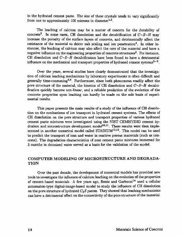
ABSTRACTCalcium hydroxide is one of the main reaction products resulting from the hydrationof Portland cement with water. It is also one of the more soluble phases found in hy-drated cement systems. The influence of calcium hydroxide dissolution and its effecton the diffusion properties of hydrated cement pastes were investigated using the NISTCEMHYD3D cement hydration and microstructure development model. The resultsof these simulations were implemented in another numerical model called STADIUM.This latter model can be used to predict the transport of ions in unsaturated poroussystems. Numerical simulations clearly indicate that calcium hydroxide dissolutioncontributes to a marked increase in the porosity of the hydrated ceme1l.t paste. Thisincrease in porosity has a detrimental influence on the material transport properties.The results yielded by the numerical simulations are in good agreement with data ofcalcium leaching experiments performed in deionized water.
INTRODUCTION
Calcium hydroxide (CH), along with C-S-H, are the end products of thereaction of alite and belite with water. The abundance of CH in the hydrated cementpaste varies with the degree of hydration of the cement, and can reach approximately26% of the total volume of a mature paste. Contrary to the G-s-H gel that is an ill-crystallized phase, CH is present predominantly in the form of well-defined crystals
To the extent authorized under the laws of the United States of America, all copyright interests in this publication are the propertyof The American Ceramic Society. Any duplication, reproduction, or republication of this publication or any part thereof, withoutthe express written consent of The American Ceramic Society or fee paid to the Copyright Clearance Center, is prohibited.
113Calcium Hydroxide in Concrete
in the hydrated cement paste. The size of these crystals tends to vary significantlyfrom one to approximately 100 microns in diameterl,2.
The leaching of calcium may be a matter of concern for the durability ofconcrete3. In some cases, CH dissolution and the decalcification of C-S-H mayincrease the porosity of the surface layers of concrete, and detrimentally affect theresistance of the material to deicer salt scaling and ion penetration4. In other in-stances, the leaching of calcium may also affect the core of the material and have anegative influence on the engineering properties of concrete structures3. For instance,CH dissolution and C-S-H decalcification have been found to have a detrimentalinfluence on the mechanical and transport properties of hydrated cement systems5-9.
Over the years, several studies have clearly demonstrated that the investiga-tion of calcium leaching me<:hanisms by laboratory experiments is often difficult andgenerally time-consuming8,9. F\1rthermore, since both phenomena readily affect thepore structure of the material, the kinetics of CH dissolution and C-S-H decalci-fication quickly become non-linear, and a reliable prediction of the evolution of theconcrete properties upon leaching can hardly be made on the sole basis of experi-mental results.
This paper presents the main results of a study of the influence of CH dissolu-tion on the mechanisms of ion transport in hydrated cement systems. The effects ofCH dissolution on the pore structure and transport properties of various hydratedcement paste mixtures were investigated using the NIST CEMHYD3D cement hy-dration and microstructure development modellO,ll. These results were then imple-mented in another numerical model called STADIUM12,13. This model can be usedto predict the transport of ions and water in reactive porous materials (such as con-crete). The degradation characteristics of neat cement paste mixtures immersed for3 months in deionized water served as a basis for the validation of the model.
COMPUTER MODELING OF MICROSTRUCTURE AND DEGRADA-TION
Over the past decade, the development of numerical models has provided newtools to investigate the influence of calcium leaching on the evolution of the propertiesof cement-based materials. A few years ago, Bentz and Garboczi14 used a cellularautomaton-type digital-image-based model to study the influence of CH dissolutionon the pore structure of hydrated C3S pastes. They showed that leaching mechanismscan have a detrimental effect on the connectivity of the pore structure of the material.
Materials Science of Concrete114
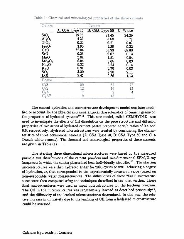
A: CSA Type 1019.784.390.223.00
62.040.262.840.040.320.913.202.41
B:-CSA Type 50C: WhiteSiO2AhO3TiO2F~O3CaOSrOMgOMn203Na20K20803LOI
The cement hydration and microstructure development model was later modi-fied to account for the physical and mineralogical characteristics of cement grains onthe properties of hydrated systemsIO,II. This new model, called CEMHYD3D, wasused to investigate the effects of CH dissolution on the pore structure and diffusionproperties of two series of hydrated cement pastes prepared at w jc ratios of 0.4 and0.6, respectively. Hydrated microstructures were created by considering the charac-teristics of three commercial cements (A: CSA Type 10, B: CSA Type 50 and C: aDanish white cement). The chemical and mineralogical properties of these cementsare given in Table (1).
The starting three dimensional microstructures were based on the measuredparticle size distributions of the cement powders and two-dimensional gEM/X-rayiplage sets in which the clinker phases had been individually identified 15. The startingmicrostructures were then hydrated either for 2000 cycles or until achieving a degreeof hydration, Q, that corresponded to the experimentally measured value (based onnon-evaporable water measurements). The diffusivities of these "final" microstruc-tures were then computed using the techniques described in the next section. Thesefinal microstructures were used as input microstructures for the leaching program.The CH in the microstructures was progressively leached as described previously14,and the diffusivity of the leached microstructures determined. In this way, the rela-tive increase in diffusivity due to the leaching of CH from a hydrated microstructurecould be assessed.
Calcium Hydroxide in Concrete
21.45 24.293.58 1.710.21 0.074.38 0.32
63.93 68.600.07 0.131.81 0.540.05 0.030.24 0.140.70 0.032.28 2.110.86 1.13
COMPUTATION OF DIFFUSIVITY
An electrical analogy is used to compute the relative diffusivity of the compositemedia16, where relative diffusivity is the ratio of the diffusivity of an ion in th~composite media relative to its value in bulk water (proportional to the inverse ofthe formation factor). Conductivities are assigned to each phase comprising themicrostructure and the resultant composite relative conductivity is computed17 andrelated to a relative diffusivity using the Nernst-Einstein relation16:
D 0"-=-Do 0"0 (1~
where a / ao is the computed relative conductivity and D / Do is the relative diffusivit.)!for the random microstructure. For this study, capillary pores (tjJ) are assigned ~relative diffusivity of 1.0, while the C-S-H gel is assigned a relative diffusivity of0.0025 (1/400)17.
Previous studies have indicated that diffusivities computed using these rel4-ative values compare favorably to those measured experimentally17-18. For eaclthydrated/leached microstructure, the diffusivity was computed in each of the threeprincipal directions and the average value reported.
MODELING IONIC TRANSPORT IN CEMENT SYSTEMS
As previously mentioned, the numerical results yielded by' the NISiCEMHYD3D model were implemented in another model called STADIUM12.13. Thislatter model has been developed to predict the transport of ions in unsaturatedporous media. The model also accounts for the effect of dissolution/precipitatio~reactions on the transport mechanisms.
The description of the various transport mechanisms relies on the homogenizattion technique. This approach first requires writing all the basic equations at thfmicroscopic level. These equations are then averaged over a Representative Elemen~tary Volume (REV) in order to describe the transport mechanisms at the macroscopiCscale19,20.
In this model, ions are considered to be either free to move in the liquid Phase~boun~ to the .solid phase. The transport of ions in the liq~id phase at.the.microscopi
level IS described by the extended Nernst-Planck equatl0n21 to whIch IS addedadvection term. After integrating this equation over the REV, the transport equatio*
Materials Science of Concrete116
becomes:
a((l- c/J)Cis) + 8(8Ci)at at
.O- (fJD'~ fJ~C,.~ fJD'C.?ln"Yi -a.vax t ax + RT tax + t t ax t x /
where the uppercase symbols represent the variables averaged over the REV. Inequation (2), Ci is the concentration of the species i in the aqueous phase, Cis is theconcentration in solid phase, fJ is the volumetric water content (expressed in m3/m3of material), Di is the diffusion coefficient, zi is the valence number of the species,F is the Faraday constant, R is the ideal gas constant, T is the temperature of theliquid, II! is the electrical potential, 1i is the chemical activity coefficient and Vx isthe velocity of the fluid. Equation (2) has to be written for each ionic species presentin the system.
To calculate the chemical activity coefficients, several approaches are available.However, models such as those proposed by Debye-Hiickel or Davies are unable toreliably describe the thermodynamic behavior of highly concentrated electrolytessuch as the hydrated cement paste pore solution. A modification of the Daviesequation described in reference22 was found to yield good results.
The Poisson equation is added to the model to evaluate the electrical potentialIll. It relates the electrical potential to the concentration of each ionic species23. Theequation is given here in its averaged form:
a- (eT~~'ax ax
NFI +8-LziCi=O (3)
E .t=l
where N is the total number of ionic species, E is the dielectric permittivity of themedium, in this case water, and T is the tortuosity of the porous network.
The velocity of the fluid, appearing in equation (2) as V x" can be described by adiffusion equation when its origin is in capillary forces present during drying/wetting
cycles24:aeVx = -Dw- a (4)x
where Dw is the non-linear water diffusion coefficient. This parameter varies accord-ing to the water content of the material24.
To complete the model, the mass conservation of the liquid phase must betaken into account24:
Of} ) = 0Dwa.:;;-
117Calcium Hydroxide in Concrete
As can be seen, moisture transport is described in terms of a variation of the (liquid)water content of the material. It should be emphasized that the choice of using thematerial water content as the state variable for the description of this problem hasan important implication on the treatment of the boundary conditions. Since thelatter are usually expressed in terms of relative humidity, a conversion has to bemade. This can be done using an adsorption/desorption isotherm24.
The first term on the left-hand side of equation (2) (in which Cis appears),accounts for the ionic e,xchange between the solution and the solid19. It can be usedto model the influence ofprecipitationjdissolution reactions on the transport process.More information on this procedure can be found in reference12.
The transport of ions and water in unsaturated cement systems can be fullydescribed on the basis of equations (2) to (5). Previous experience12 has shown thatmost practical problems can be reliably described by seven different ionic species(OH-, Na+,K+, SO~-, Ca2+, AI(OH); and CI-) and five solid phases (CH, G-S-H,ettringite, gypsum and hydrogarnet).
The input data required to run the model can be easily obtained. The initialcomposition of the material (i.e. its initial content in CH, ettringite, ...) can be easilycalculated by considering the chemical (and mineralogical) make-up of the binder,the characteristics of the mixture and the degree of hydration of the system25.
The model also requires determining the initial composition of the pore solutionand the porosity of the material. Samples of the pore solution of most hydratedcement systems can be obtained by extraction using the technique described byLonguet et al.26. The total porosity of the material can easily be determined in thelaboratory following standardized procedures (such as ASTM C642)27.
Some information on the transport properties of the material is also requiredto run the model. The ionic: diffusion properties of the solid can be determined by amigration test12. The water diffusion coefficient of the material can be assessed bynuclear magnetic resonance imaging24.
LEACHING EXPERIMENTS
In order to validate the results of the numerical simulations, six different cementpaste mixtures were prepared with the three cements described in Table (1) andat two water/cement ratios (0.4 and 0.6). Only the results obtained for the 0.6water/cement ratio mixture made of the CSA Type 10 cement (cement A) will be
lIS Materials Science of Concrete
reported. Data obtained for the other mixtures will be discussed in a forthcomingpublication.
All mixtures were prepared using deionized water. The mixtures were batchedin a high-speed mixer placed under vacuum (at 10 mbar) to prevent, as much aspossible, the formation of air voids during mixing. Mixtures were cast in plasticcylinders (diameter = 7.0 cm, height = 20 cm). The molds were sealed and rotatedfor the first 24 hours in order to prevent any bleeding of the mixtures. At the endof this period, the cylinders were demoulded and sealed with an adhesive aluminumfoil for an I8-month period at room temperature. This period was selected in orderto get mature and well-hydrated cement pastes.
After the I8-month curing period, samples of each mixture were subjectedto migration tests, porosity measurements pore solution extractions and thermalanalyses (to assess the degree of hydration of each system). The experimental proce-dures for the migration tests and the pore solution extractions have been describedelsewhere28,29. Porosity measurements were carried out according to the require-ments of ASTM C 64227. The water diffusion properties of these mixtures had beenpreviously determined by Nuclear Magnetic Resonance Imaging (NMRI) as part ofa previous project30.
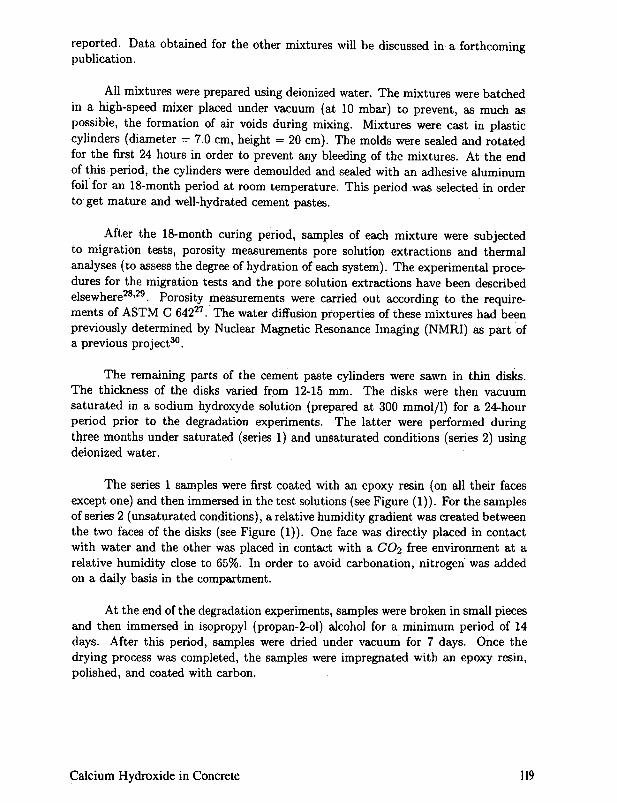
The remaining parts of the cement paste cylinders were sawn in thin disks.The thickness of the disks varied from 12-15 mm. The disks were then vacuumsaturated in a sodium hydroxy de solution (prepared at 300 mmol/l) for a 24-hourperiod prior to the degradation experiments. The latter were performed duringthree months under saturated (series 1) and unsaturated conditions (series 2) usingdeionized water.
The series 1 samples were first coated with an epoxy resin (on all their facesexcept one) and then immersed in the test solutions (see Figure (1)). For the samplesof series 2 (unsaturated conditions), a relative humidity gradient was created betweenthe two faces of the disks (see Figure (1)). One face was directly placed in contactwith water and the other was placed in contact with a CO2 free environment at arelative humidity close to 65%. In order to avoid carbonation, nitrogen was addedon a daily basis in the compartment.
At the end of the degradation experiments, samples were broken in small piecesand then immersed in isopropyl (propan-2-ol) alcohol for a minimum period of 14days. After this period, samples were dried under vacuum for 7 days. Once thedrying process was completed, the samples were impregnated with an epoxy resin,polished, and coated with carbon.
Calcium Hydroxide in Concrete 119
Figure 1: Degradation test set-up.
Microstructural alterations of the cement paste samples were investigated bymeans of electron microprobe analyses. The polished sections were observed usinga microprobe (Cameca SX-100) 1 operating at 15 kV and 20 nA. For each sample,
measurements were performed at a maximum interval of 13 microns on four distinctimaginary lines extending from the external surface in contact with the aggressivesolution toward the internal part of the samples. At each point of measurement,the total content of calcium, sulfur, sodium, potassium, silicon, and aluminum wasdetermined.
RESULTS AND DISCUSSION
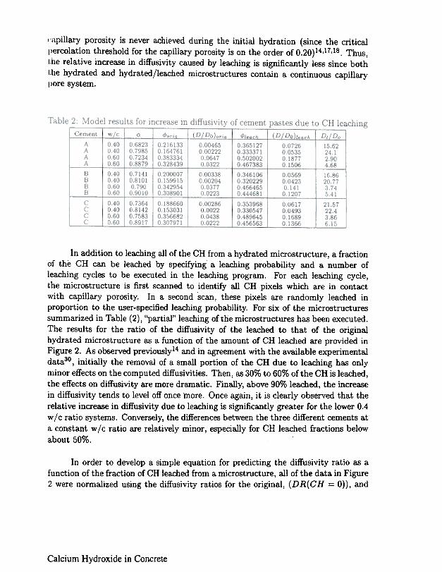
Numerical results obtained with the NIST CEMHYD3D cement hydration andmicrostructure development model clearly indicate that leaching has a significant ef-fect on the diffusivity of cement pastes. The diffusivity values calculated with themodel for the original and completely leached microstructures are summarized in Ta-ble (2). In agreement with previous results for simpler C3S systemsl4, the increasein diffusivity due to leaching is seen to be a factor of 20 or more, depending on theinitial w j c ratio and the degree of hydration achieved prior to leaching. Addition-ally, the increase in diffusivity is seen to be much more dramatic for the lower wjcratio systems, due mainly to the re-percolation of the capillary pore network duringthe leaching of the CH. For the higher w/c ratio systems, the depercolation of the
lCertain commercial equipment is identified by name in this paper to adequately specify theexperimental procedure. In no case does such identification imply endorsement by the NationalInstitute of Standards and Technology, nor does it imply that the products are necessarily the bestavailable for the purpose.
120 Materials Science of Concrete
";1,pillary porosity is never achieved during the initial hydration (since the criticalI)ercolation threshold for the capillary porosity is on the order of 0.20)14.17.18. Thus,I,he relative increase in diffusivity caused by leaching is significantly less since bothI,he hydrated and hydrated/leached microstructures contain a continuous capillaryI lore system.
In addition to leaching all of the CH from a hydrated microstructure, a fractionof the CH can be leached by specifying a leaching probability and a number ofleaching cycles to be executed in the leaching program. For each leaching cycle,the microstructure is first scanned to identify all CH pixels which are in contactwith capillary porosity. In a second scan, these pixels are randomly leached inproportion to the user-specified leaching probability. For six of the microstructuressummarized in Table (2), "partial" leaching of the microstructures has been executed.The results for the ratio of the diffusivity of the leached to that of the originalhydrated microstructure as a function of the amount of CH leached are provided inFigure 2. As observed previously14 and in agreement with the available experimentaldata30, initially the removal of a small portion of the CH due to leaching has onlyminor effects on the computed diffusivities. Then, as 30% to 60% of the CH is leached,the effects on diffusivity are more dramatic. Finally, above 90% leached, the increasein diffusivity tends to level off onc:e more. Once again, it is clearly observed that therelative increase in diffusivity due to leaching is significantly greater for the lower 0.4w / c ratio systems. Conversely, the differences between the three different cements ata constant w / c ratio are relatively minor, especially for CH leached fractions belowabout 50%.
In order to develop a simple equation for predicting the diffusivity ratio as afunction of the fraction of CH leached from a microstructure, all of the data in Figure2 were normalized using the diffusivity ratios for the original, (DR(CH = 0)), and
Calcium Hydroxide in Concrete
.I .I .I .I .I .I .I .1. I .,
0- Cement A wjc=O.400- Cement B wjc=O.40
~fI- Cement C wjc=O.40 0- Cement A wjc=0.60
v- Cement B wjc=O.60*- Cement C wjc=O.60 ~!
200
-'.,...>.-'>m='
--
Q
15/
/~
10 /
5
0 ~, }- '-'- ' -'- " " ' I .,. I ' I ' I
0 10 20 30 40 50 60 70 80 90 100
CH leached (%)
Figure 2: Model results for increase in diffusivity of cement pastes due to leachingofCH
completely leached, (DR(GH :: 100)), microstructures and the following equation
(6)
It can be easily observed that this will result in normalized diffusivities (D N) withvalues between 1 and 2 for every case.
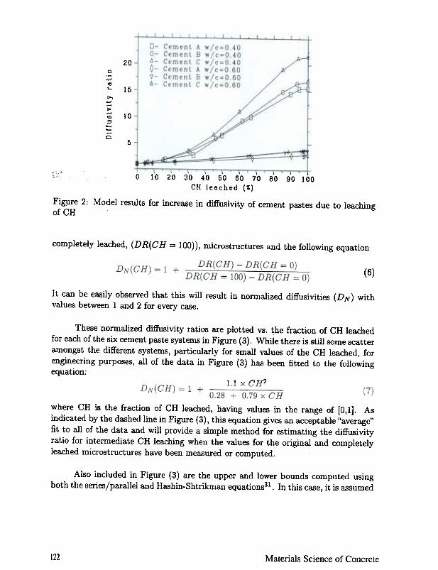
These normalized diffusivity ratios are plotted vs. the fraction of CH leachedfor each of the six cement paste systems in Figure (3). While there is still some scatteramongst the different systems, particularly for small values of the CH leached, forengineering purposes., all of the data in Figure (3) has been fitted to the followingequation:
1.1 X CH2
Also included in Figure (3) are the upper and lower bounds computed usingboth the series/parallel and Hashin-Shtrikman equations31. In this case, it is assumed
122 Materials Science of Concrete
where CH is the fraction of CH leached, having values in the range of (0,1]. Asindicated by the dashed line in Figure (3), this equation gives an acceptable "average"fit to all of the data and will provide a simple method for estimating the diffusivityratio for intermediate CH leacJ:ling when the values for the original and completelyleached microstructures have been measured or computed.
2to
0
-'10..>,-'>'":I
~~QIN
:= I10
e..0:z
0- Cement0- Cement6- Cement0- Cement1;- CementR- Cement
!J!O
1 -I
0 10 20 30 40 50 60 70 80 90 100CH leached (~)
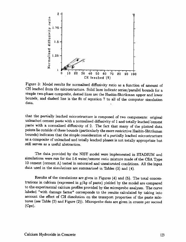
Figure 3: Model results for normalized diffusivity ratio as a function of amount ofCH leached from the microstructure. Solid lines indicate series/parallel bounds for a
simple two-phase composite, dotted lines are the Hashin-Shtrikman upper and lowerbounds, and dashed line is the fit of equation 7 to all of the computer simulationdata.
that the partially leached microstructure is composed of two components: originalunleached cement paste with a normalized diffusivity of 1 and totally leached 'cementpaste with a normalized diffusivity of 2. The fact that many of the plotted datapoints lie outside of these bounds (particularly the more restrictive Hashin-Shtrikmanbounds) indicates that the simple consideration of a partially leached microstructureas a composite of unleached and totally leached phases is not totally appropriate butstill serves as a useful abstraction.
The data provided by the NIST model were implemented in STADIUM andsimulations were run for the 0.6 water/cement ratio mixture made of the CSA Type10 cement (cement A) tested in saturated and unsaturated conditions. All the inputdata used in the simulations are summarized in Tables (3) and (4).
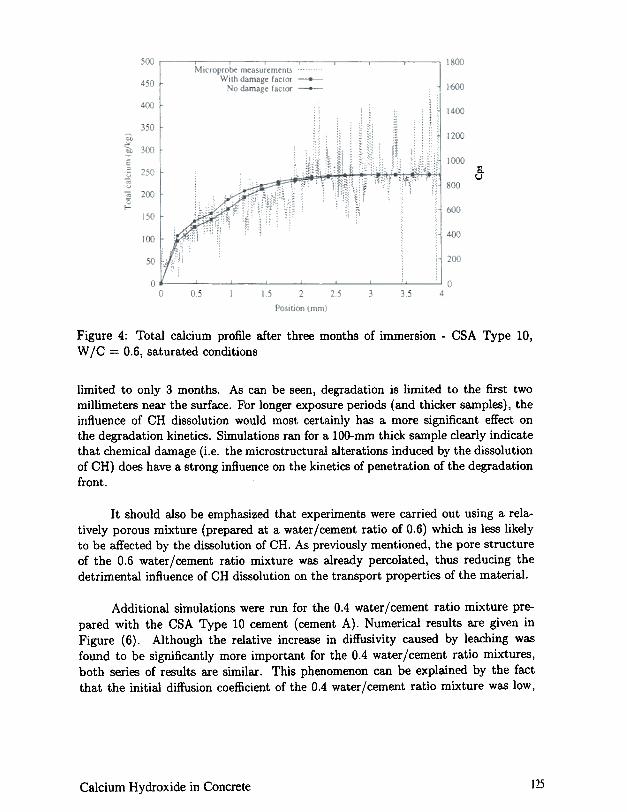
Results of the simulations are given in Figures (4) and (5). The total concen-trations in calcium (expressed in gjkg of paste) yielded by the model are comparedto the experimental calcium profiles provided by the microprobe analyses. The curvelabeled "with damage factor" corresponds to the results calculated by taking intoaccount the effect of CH dissolution on the transport properties of the paste mix-tures (see Table (2) and Figure (2)). Microprobe data are given in counts per second
(Cps).
Calcium Hydroxide in Concrete 123
1.75
1.5
1.25
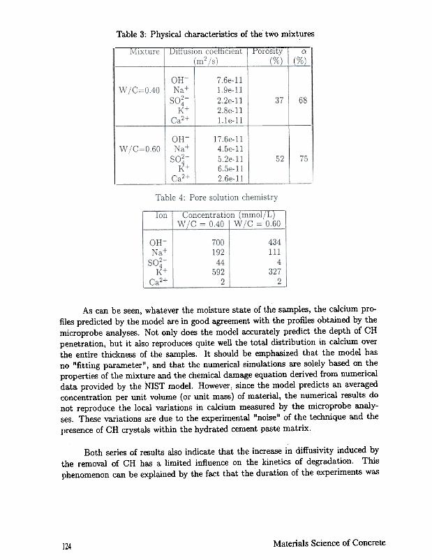
Table 3: Physical characteristics of the two mixturesjviixture Diffusion coefficient Porosity Q .
(m2/s) (%) (%)
W/C=OAO68
W jC=O.6075
As can be seen, whatever the moisture state of the samples, the calcium pro-files predicted by the model are in good agreement with the profiles obtained by themicroprobe analyses. Not only does the model accurately predict the depth of CHpenetration, but it also reproduces quite well the total distribution in calcium overthe entire thickness of the samples. It should be emphasized that the model hasno "fitting parameter", and that the numerical simulations are solely based on theproperties of the mixture and the chemical damage equation derived from numericaldata provided by the NIST model. However, since the model predicts an averagedconcentration per unit volume (or unit mass) of material, the numerical results donot reproduce the local variations in calcium measured by the microprobe analy-ses. These variations are due to the experimental "noise" of the technique and thepresence of CH crystals within the hydrated cement paste matrix.
Both series of results also indicate that the increase in diffusivity induced bythe removal of CH has a limited influence on the kinetics of degradation. Thisphenomenon can be explained by the fact that the duration of the experiments was
Materials Science of Concrete124
Sou
Figure 4: Total calcium profile after three months of immersion -CSA Type 10,W /C = 0.6, saturated conditions
limited to only 3 months. As can be seen, degradation is limited to the first twomillimeters near the surface. For longer exposure periods (and thicker samples), theinfluence of CH dissolution would most certainly has a more significant effect onthe degradation kinetics. Simulations ran for a lOO-mm thick sample clearly indicatethat cllemical damage (i.e. the microstructural alterations induced by the dissolutionof CH) does have a strong influence on the kinetics of penetration of the degradationfront.
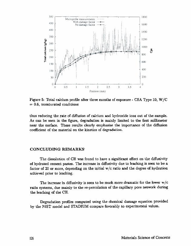
It should also be emphasized that experiments were carried out using a rela-tively porous mixture (prepared at a water/cement ratio of 0.6) which is less likelyto be affected by the dissolution of CR. As previously mentioned, the pore structureof the 0.6 water/cement ratio mixture was already percolated, thus reducing thedetrimental influence of CR dissolution on the transport properties of the material.
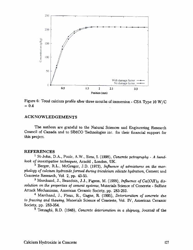
Additional simulations were run for the 0.4 water/cement ratio mixture pre-pared with the CSA Type 10 cement (cement A). Numerical results are given inFigure (6). Although the relative increase in diffusivity caused by leaching wasfound to be significantly more important for the 0.4 water/cement ratio mixtures,both series of results are similar. This phenomenon can be explained by the factthat the initial diffusion coefficient of the 0.4 water/cement ratio mixture was low,
125Cal{;ium Hydroxide in Concrete
'Of,
~E='u;;u;;~
~u
Figure 5: Total calcium profile after three months of exposure -CSA Type 10, W jC= 0.6, unsaturated conditions
thus reducing the rate of diffusion of calcium and hydroxide ions out of the sample.As can be seen in the figure, degradation is mainly limited to the first millimeternear the surface. These results clearly emphasize the importance of the diffusioncoefficient of the material on the kinetics of degradation.
CONCLUDING REMARKS
The dissolution of CH was found to have a significant effect on the diffusivityof hydrated cement pastes. The increase in diffusivity due to leaching is seen to be afactor of 20 or more, depending on the initial wlc ratio and the degree of hydrationachieved prior to leaching.
The incre~e in diffusivity is seen to be much more dramatic for the lower wjcratio systems, due mainly to the re-percolation of the capillary pore network duringthe leaching of the CH.
Degradation profiles computed using the chemical damage equation providedby the NIST model and STADIUM compare favorably to experimental values.
Materials Science of Concrete126
0.5 1.5 2.5 3.52
Position (nun)
Figure 6: Total calcium profile after three months of immersion -CSA Type 10 W /C= 0.4
ACKNOWLEDGEMENTS
The authors are grateful to the Natural Sciences and Engineering ResearchCouncil of Canada and to SIMCO Technologies inc. for their financial support forthis project.
REFERENCES1 St-John, D.A., Poole, A.W., Sims, I. (1998), Concrete petrogmphy -A hand-
book of investigative techniques, Arnold, London, UK.2 Berger, R.L., McGregor, J.D. (1972), Influence of admixtures on the mor-
phology of calcium hydroxide formed during tricalcium silicate hydration, Cement andConcrete Research, Vol. 2, pp. 43-55.
3 Marchand, J., Beaudoin, J.J., Pigeon, M. (1999), Influence of Ga(OH)2 dis-
solution on the properties of cement systems, Materials Science of Concrete -SulfateAttack Mechanisms, American Ceramic Society, pp. 283-293.
4 Marchand, J., Pleau, R., Gagne, R. (1995), Deterioration of concrete due
to freezing and thawing, Materials Science of Concrete, Vol. IV, American CeramicSociety, pp. 283-354.
5 Terzaghi, R.D. (1948), Concrete deterioration in a shipway, Journal of the
127Calcium Hydroxide in Concrete
American Concrete Institute, Vol. 44, No.6, pp. 977-1005.6 Tremper, B. (1931), The effects of acid waters on concrete, Journal of the
American Concrete Institute, Vol. 28, No.9, pp. 1-32.7 Carde, C., Fran~ois, R. (1997), Effect of the leaching of calcium hydroxide
from cement paste on the mechanical and physical properties, Cement and Concr~teResearch, Vol. 27, pp. 539-550.
8 Adenot, F., Buil, M. (.1992), Modelling the corrosion of the cement paste by
deionized water, Cement and Concrete Research, Vol. 22, pp. 489-496.9 Delagrave, A., GerardI, G., Marchand, J. (1997), Modelling calcium leaching
mechanisms in hydrated cement pastes, in Mechanisms of Chemical Degradation ofCement-Based Materials, E & FN Spon, pp. 38-49.
10 Bentz, D.P. (1997), Three-dimensional computer simulation of cement hy-
dration and microstructure development, Journal of the American Ceramic Society,Vol. 80, No.1, pp. 3-21.
11 Bentz, D.P. (2000), CEMHYD3D: A three-dimensional cement hydration
and microstructure development modelling package. Version 2.0, NISTIR 6485, U.S.Department of Commerce.
12 Marchand, J. (2000), Modeling the behavior of unsaturated cement system-
sexposed to aggressive chemical environments, Materials and Structures, (in press).13 Samson, E. (2000), Modeling ion transport mechanisms in unsaturated ce-
ment systems, Ph. D. thesis, Department of Civil Engineering, Laval University,
Canada, (in preparation).14 Bentz, D.P., Garboczi, E.J. (1992), Modelling the leaching of calcium hydrox-
ide from cement paste: Effects on pore space percolation and diffusivity, Materialsand Structures, Vol. 25, pp. 523-533.
15 Bentz, D.P., StutzmaIl, P.E. (1994), SEM analysis and computer modelling
of hydration of portland cement particles, in Petrography of Cementitious Systems,ASTM STP-1215, Ed. S.M. DeHayes and D. Stark, American Society for Testingand Materials, Philadelphia, pp. 60-73.
16 Garboczi, E.J. (1998), Finite element and finite difference programs for
computing the linear electric and elastic properties of digitial images of random ma-terials, NISTIR 6269, U.S. Department of Commerce, (see http:/ /ciks.cbt.nist.gov/
monograph/, Chapter 2).17 Garboczi, E.J., Bentz, D.P. (1992), Computer simulation of the diffusivity
of cement-based materials, Journal of Materials Science, Vol. 27, pp. 2083-2092.18 Bentz, D.P., Jensen, O.M., Glasser, F.P., Coats, A.M. (2000), Influence
of silica fume on diffusivity if! cement-based materials -Part I: Experimental andcomputer modelling studies on cement pastes, Cement and Concrete Research, Vol.30, pp 953-962.
19 Bear, J., Bachmat, Y. (1991), Introduction to modeling of transport phe-
nomena in porous media, Kluwer Academic Publishers, The Netherlands.
128 Materials Science of Concrete
20 Samson, E., Marchand, J., Beaudoin, J.J. (1999), Describing ion diffusion
mechanisms in cement-based materials using the homogenization technique, Cementand Concrete Research, Vol. 29, No.8, pp.1341-1345.
21 Helfferich, F. (1962), Ion exchange, McGraw-Hill, New York, USA, 624 p.'22 Samson, E., Lemaire, G., Marchand, J., Beaudoin, J.J., (1999), Modeling
chemical activity effects in strong ionic solutions, Computational Materials Science,Vol. 15, pp. 285-294.
23 Samson, E., Marchand, J., Robert, J.L., Bournazel, J.P. (1999), Modeling
the mechanisms of ion diffusion tmnsport in porous media, International Journal ofNumerical Methods in Engineering, Vol. 46, pp. 2043-2060.
24 Pel, L. (1995), Moisture transport in porous building materials, Ph. D.
thesis, Eindhoven University of Technology, The Netherlands, 125 p.25 Taylor, H.F.W. (1990), Cement chemistry, Academic Press Inc., ~an Diego,
USA26 Longuet, P., Burglen, L., Zelwer, A. (1980), The liquid phase of hydroted
cement, Publication Technique CERILH, Vol. 219, (in French).27 Jacobsen, S., Marchand, J., Boisvert, L. (1996), Effect of crocking and heal-
ing on chloride tronsport in OPC concrete, Cement Concrete Research, Vol. 26, No.6, pp. 869-882.
28Diarnond, S. (1981), Effects of two Danish fly ashes on alkali contents of poresolutions of cement fly ash pastes, Cement and Concrete Research, Vol. 11, No.2,pp. 383-390.
29 Hazrati, K. (1995), Investigation of the mechanisms of moisture tronsport
by capillary suction in ordinary and high-performance cement-based materials, Ph.D. thesis, Laval University, Canada, 205 p.
30 Revertegat, E., Richet, C., Gegout, P. (1992), Effect of pH on the durability
of cement pastes, Cement and Concrete Research, Vol. 22, pp. 259-272.31 Kuntz, M., Mareschal, J.C., Lavallee, P. (1997), Numerical estimation of
the effective conductivity of heterogeneous media with a 2D cellular automaton fluid,Geophysical Research Letters, Vol. 24, No. 22, pp. 2865-2868, online at: http:/ /www.agu.org/GRL/articles/97GL52856/ GL136W01.html.
129Calcium Hydroxide in Concrete