Embed Size (px)
Citation preview
INTERNATIONAL JOURNAL OF CIVIL AND STRUCTURAL ENGINEERING
Volume 3, No 1, 2012
© Copyright by the authors - Licensee IPA- Under Creative Commons license 3.0
Research article ISSN 0976 – 4399
Received on June, 2012 Published on August 2012 214
Influence of diagonal braces in RCC multi-storied frames under wind
loads: A case study
Suresh P1, Panduranga Rao B
2, Kalyana Rama J.S
3
1- Post Graduate Student, Civil Engineering Department, V. R. Siddhartha
Engineering College, Vijayawada, Andhra Pradesh, India
2- Professor and Head, Civil Engineering Department, V. R. Siddhartha Engineering
College, Vijayawada, Andhra Pradesh, India
3- Assistant Professor, Civil Engineering Department, V. R. Siddhartha Engineering
College, Vijayawada, Andhra Pradesh, India
doi:10.6088/ijcser.201203013021
ABSTRACT
Structures are classified as rigid and flexible. Tall structures are more flexible and susceptible
to vibrations by wind induced forces. In the analysis and design of high-rise structures
estimation of wind loads and the inter storey drifts are the two main criteria to be positively
ascertained for the safe and comfortable living of the inhabitants. Estimation of wind loads is
more precise with gust factor method. Inter storey drift can be controlled through suitable
structural system. The present investigation deals with the calculation of wind loads using
static and gust factor method for a sixteen storey high rise building and results are compared
with respect to drift. Structure is analyzed in STAAD Pro, with wind loads calculated by gust
factor method as per IS 875-Part III with and without X- bracings at all the four corners from
bottom to top.
Keywords: Wind analysis, gust factor, inter-storey drift, drift.
1. Introduction
In the case of static structures the flow interacts only with the external shape of the structure.
When the structure is very stiff deflections under the wind loads will not be significant, and
the structure is said to be "Static''. The only design loading parameter of importance is the
maximum load likely to be experienced in its lifetime. The parameters most relevant to the
assessment of design loading are Influence functions, size parameters of the structure, load
duration and assessment of load for design. In the case of dynamic structures, there is an
additional interaction with the motion of the structure. When the structure is sufficiently
flexible, the response to wind loads is significant to the design of the structure. The
conventional approach to the analysis of dynamic response of lightly damped structures is by
resolving the response into the natural modes of vibration, characterizing each normal mode
as a set of model parameters: 1) Model shape, 2) Model mass, 3) Model stiffness and 4)
Model damping. Using these parameters a frequency response function can be defined that
describes the dynamic characteristics of the structures. Gust Effectiveness Factor method is a
more realistic and rational approach to deal with wind loads on tall building towers. Various
studies have also been made regarding the provision of steel braces and infill walls. (T. El-
Amoury et.al, 2005) developed two rehabilitation techniques were proposed to improve the
dynamic response of framed structures. Fiber reinforced polymer (FRP) jackets were used as
a local rehabilitation technique to enhance the joint shear strength and ductility. As another
Influence of diagonal braces in RCC multi-storied frames under wind loads: A case study
Suresh P, Panduranga Rao B, Kalyana Rama J.S
International Journal of Civil and Structural Engineering 215
Volume 3 Issue 1 2012
option, X-steel braces were installed in the middle bay of the frame along its height as an
alternate lateral load resisting system. For each frame, failure sequence and inter storey drift
were examined. It was found that FRP wrapping eliminated the brittle failure modes without
significant change in the structural response. However, steel bracing significantly contributed
to the structural stiffness and reduced the maximum inter storey drift of the frames.
(Mahmoud R. Maheri, 2005) adopted various local and global retrofitting techniques of RC
frames and used various external and internal steel bracing systems in a structure. (Mahtab
et.al, 2008)] made an economical comparison for steel plate shear wall and cross bracing
system for a ten storey bending frame using push over analysis as per FEMA 356 and it was
observed that using steel plate shear walls, the consumed steel volume is 30% lower than that
of bracings. (Pravin B. Waghmare, 2011) compared the retrofitting of RC building using steel
bracing and infill walls. Of both the methods use of structural wall in the ground storey panel
gave the maximum strength and ductility. (Cengizhan Durucan et.al, 2010) focused on a
proposed seismic retrofitting system (PRS) configured to upgrade the performance of
seismically vulnerable reinforced concrete (RC) buildings. The PRS is composed of a
rectangular steel housing frame with chevron braces and a yielding shear link connected
between the braces and the frame. The retrofitting system is installed within the bays of an
RC building frame to enhance the stiffness, strength and ductility of the structure.
The objective of this paper is to study the response of sixteen storied building with and
without the provision of corner bracings. Variations of Axial loads, moments, total drift and
inter-storey drift at different heights are presented and discussed.
2. Problem modeling
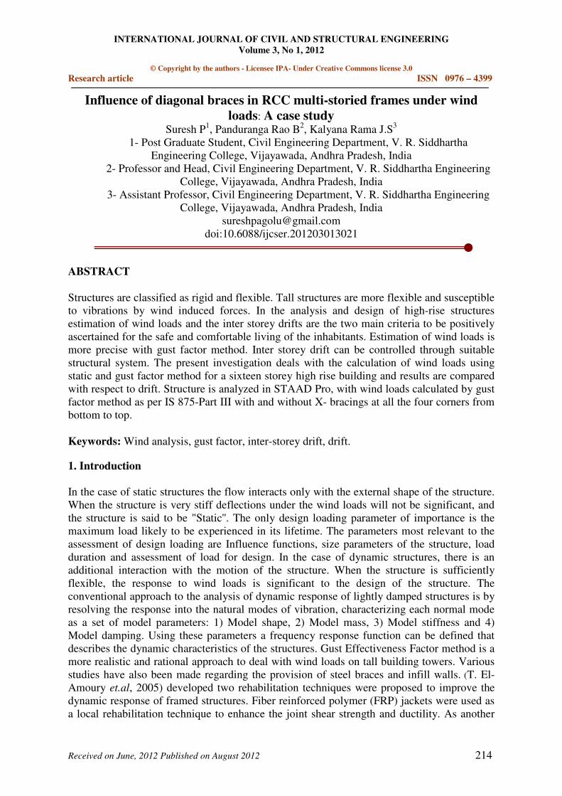
The sixteen storied building is modeled using STAAD Pro software. The structure consists of
2 bays along Z-direction and 8 bays along X-direction with a total height of 45 m.
.
Figure 1: Plan (Top view Size of the beams - 230 X 300;
Size of the Columns - 600 X 600)
2.1 Loading Conditions
Dead Load: Self weight + floor load 4KN/m2 + UDL of 12 KN/m for fifteen floors + UDL of
6 KN/ m on the roof. Live Load: Floor load 2 KN/m2. Wind pressures on the structure are
calculated manually using static and gust factor method.
Influence of diagonal braces in RCC multi-storied frames under wind loads: A case study
Suresh P, Panduranga Rao B, Kalyana Rama J.S
International Journal of Civil and Structural Engineering 216
Volume 3 Issue 1 2012
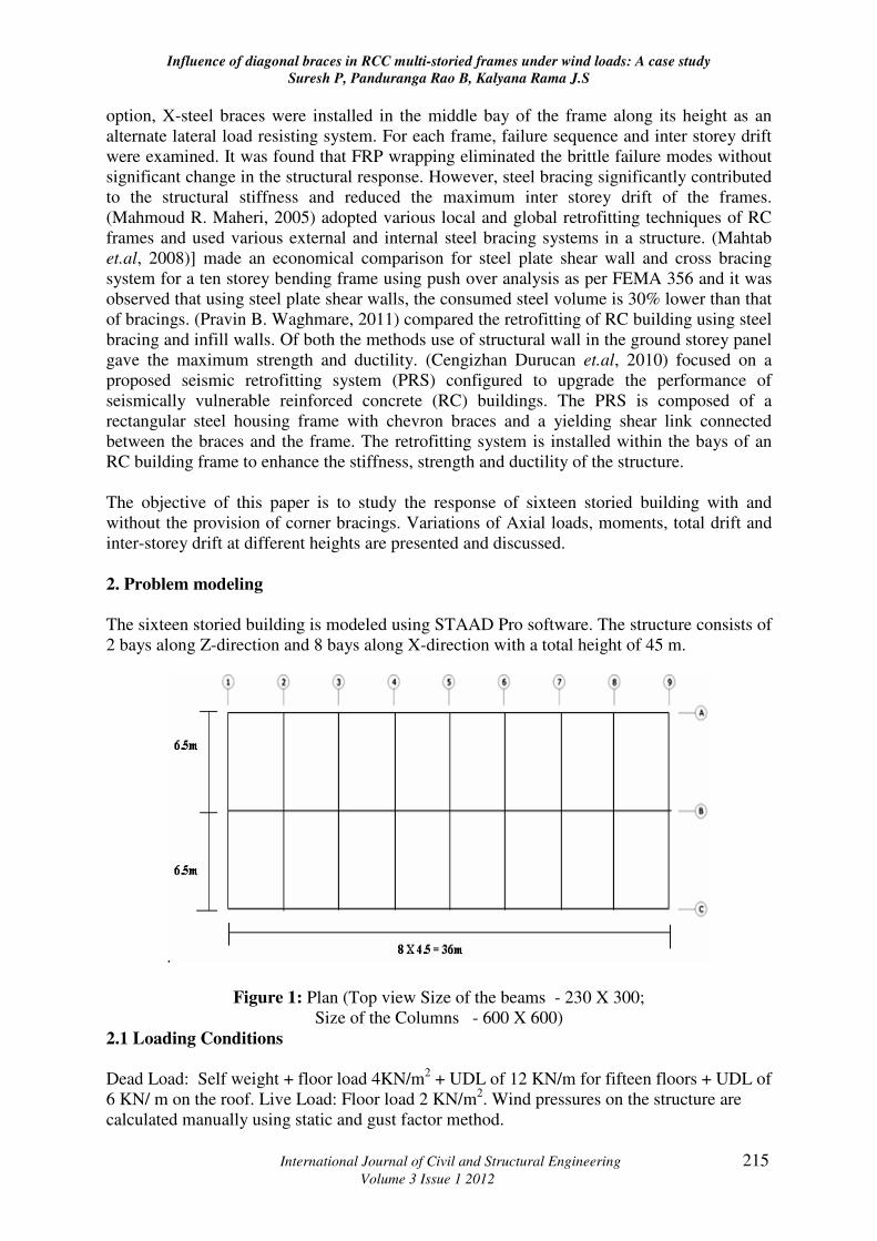
Figure 2(a): Structure without Bracings Figure 2(b): Structure with Bracings
Figure 3: Bracings in X-direction Figure 4: Bracings in Z-direction
3. Calculation of wind load
Wind load is calculated based on two different methods a) Static method and b) Gust factor
method.
3.1 Static method
The basic wind speed Vb of a region correspond to certain reference conditions as highlighted
in the earlier section, and shall be modified to include the effects of risk level, terrain
Influence of diagonal braces in RCC multi-storied frames under wind loads: A case study
Suresh P, Panduranga Rao B, Kalyana Rama J.S
International Journal of Civil and Structural Engineering 217
Volume 3 Issue 1 2012
roughness, height, structure size and local topography to obtain design wind speed, Vz in m/s
at height z for the chosen structure as given below
Vz = Vbk1 k2 k3; Where Vz = Design wind speed (in m/s) at height z
Pz = 0.6Vz2
Vb = Basic wind speed for the site (50m/s)
k1 = Probability factor or risk coefficient with return periods
k2 = Factor for the combined effects of terrain (ground roughness) height and size of the
component on structure. Table-2, Terrain category3, Class B- from IS 875 Part III- 1987)
k3 = Factor for local topography (hills, valleys, cliffs, etc.)
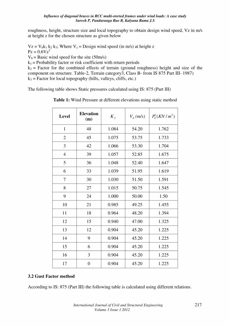
The following table shows Static pressures calculated using IS: 875 (Part III)
Table 1: Wind Pressure at different elevations using static method
Level Elevation
(m) 2K ZV (m/s) )/( 21 mKNPZ
1 48 1.084 54.20 1.762
2 45 1.075 53.75 1.733
3 42 1.066 53.30 1.704
4 39 1.057 52.85 1.675
5 36 1.048 52.40 1.647
6 33 1.039 51.95 1.619
7 30 1.030 51.50 1.591
8 27 1.015 50.75 1.545
9 24 1.000 50.00 1.50
10 21 0.985 49.25 1.455
11 18 0.964 48.20 1.394
12 15 0.940 47.00 1.325
13 12 0.904 45.20 1.225
14 9 0.904 45.20 1.225
15 6 0.904 45.20 1.225
16 3 0.904 45.20 1.225
17 0 0.904 45.20 1.225
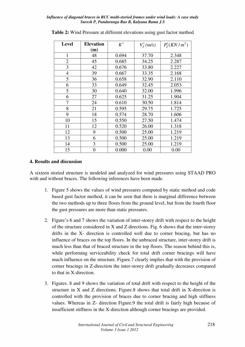
3.2 Gust Factor method
According to IS: 875 (Part III) the following table is calculated using different relations.
Influence of diagonal braces in RCC multi-storied frames under wind loads: A case study
Suresh P, Panduranga Rao B, Kalyana Rama J.S
International Journal of Civil and Structural Engineering 218
Volume 3 Issue 1 2012
Table 2: Wind Pressure at different elevations using gust factor method
Level Elevation
(m)
1K 1
ZV (m/s) )/( 21 mKNPZ
1 48 0.694 37.70 2.348
2 45 0.685 34.25 2.287
3 42 0.676 33.80 2.227
4 39 0.667 33.35 2.168
5 36 0.658 32.90 2.110
6 33 0.649 32.45 2.053
5 30 0.640 32.00 1.996
6 27 0.625 31.25 1.904
7 24 0.610 30.50 1.814
8 21 0.595 29.75 1.725
9 18 0.574 28.70 1.606
10 15 0.550 27.50 1.474
11 12 0.520 26.00 1.318
12 9 0.500 25.00 1.219
13 6 0.500 25.00 1.219
14 3 0.500 25.00 1.219
15 0 0.000 0.00 0.00
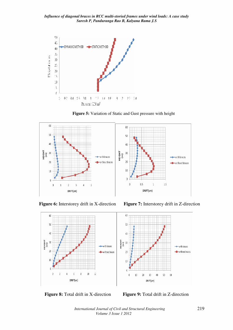
4. Results and discussion
A sixteen storied structure is modeled and analyzed for wind pressures using STAAD PRO
with and without braces. The following inferences have been made.
1. Figure 5 shows the values of wind pressures computed by static method and code
based gust factor method, it can be seen that there is marginal difference between
the two methods up to three floors from the ground level, but from the fourth floor
the gust pressures are more than static pressures.
2. Figure’s 6 and 7 shows the variation of inter-storey drift with respect to the height
of the structure considered in X and Z directions. Fig. 6 shows that the inter-storey
drifts in the X- direction is controlled well due to corner bracing, but has no
influence of braces on the top floors. In the unbraced structure, inter-storey drift is
much less than that of braced structure in the top floors. The reason behind this is,
while performing serviceability check for total drift corner bracings will have
much influence on the structure. Figure.7 clearly implies that with the provision of
corner bracings in Z-direction the inter-storey drift gradually decreases compared
to that in X-direction.
3. Figures. 8 and 9 shows the variation of total drift with respect to the height of the
structure in X and Z directions. Figure.8 shows that total drift in X-direction is
controlled with the provision of braces due to corner bracing and high stiffness
values. Whereas in Z- direction Figure.9 the total drift is fairly high because of
insufficient stiffness in the X-direction although corner bracings are provided.
Influence of diagonal braces in RCC multi-storied frames under wind loads: A case study
Suresh P, Panduranga Rao B, Kalyana Rama J.S
International Journal of Civil and Structural Engineering 219
Volume 3 Issue 1 2012
Figure 5: Variation of Static and Gust pressure with height
Figure 6: Interstorey drift in X-direction Figure 7: Interstorey drift in Z-direction
Figure 8: Total drift in X-direction Figure 9: Total drift in Z-direction
Influence of diagonal braces in RCC multi-storied frames under wind loads: A case study
Suresh P, Panduranga Rao B, Kalyana Rama J.S
International Journal of Civil and Structural Engineering 220
Volume 3 Issue 1 2012
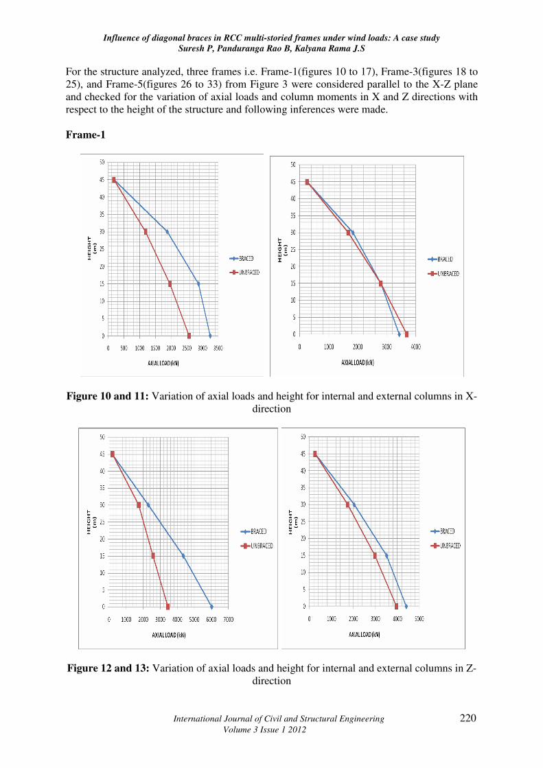
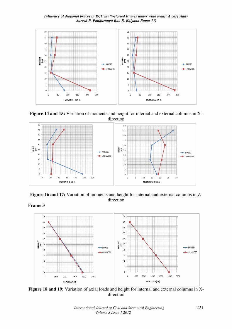
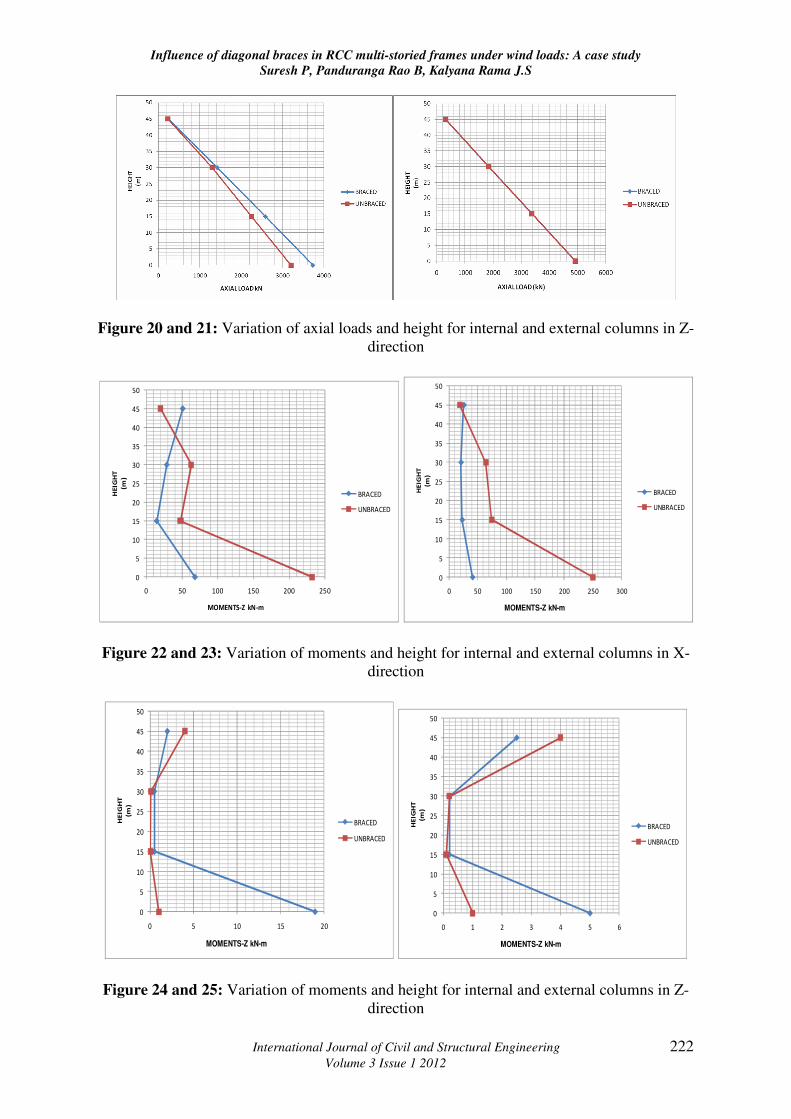
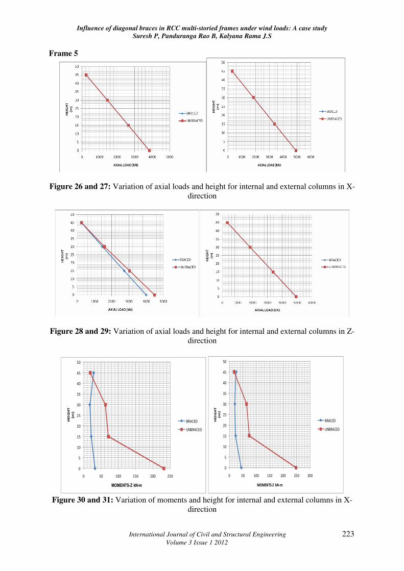
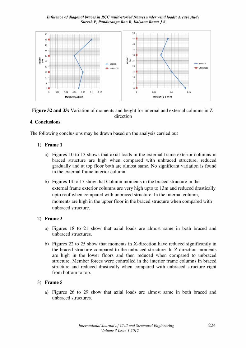
For the structure analyzed, three frames i.e. Frame-1(figures 10 to 17), Frame-3(figures 18 to
25), and Frame-5(figures 26 to 33) from Figure 3 were considered parallel to the X-Z plane
and checked for the variation of axial loads and column moments in X and Z directions with
respect to the height of the structure and following inferences were made.
Frame-1
Figure 10 and 11: Variation of axial loads and height for internal and external columns in X-
direction
Figure 12 and 13: Variation of axial loads and height for internal and external columns in Z-
direction
Influence of diagonal braces in RCC multi-storied frames under wind loads: A case study
Suresh P, Panduranga Rao B, Kalyana Rama J.S
International Journal of Civil and Structural Engineering 221
Volume 3 Issue 1 2012
0
5
10
15
20
25
30
35
40
45
50
0 50 100 150 200 250
HE
IGH
T
(m)
MOMENTS -Z kN-m
BRACED
UNBRACED
0
5
10
15
20
25
30
35
40
45
50
0 50 100 150 200 250
HE
IGH
T
(m)
MOMENTS-Z kN-m
BRACED
UNBRACED
Figure 14 and 15: Variation of moments and height for internal and external columns in X-
direction
0
5
10
15
20
25
30
35
40
45
50
0 20 40 60 80 100 120
HE
IGH
T
(m)
MOMENTS-Z kN-m
BRACED
UNBRACED
0
5
10
15
20
25
30
35
40
45
50
0 5 10 15 20 25 30
HE
IGH
T
(m)
MOMENTS-Z kN-m
BRACED
UNBRACED
Figure 16 and 17: Variation of moments and height for internal and external columns in Z-
direction
Frame 3
Figure 18 and 19: Variation of axial loads and height for internal and external columns in X-
direction
Influence of diagonal braces in RCC multi-storied frames under wind loads: A case study
Suresh P, Panduranga Rao B, Kalyana Rama J.S
International Journal of Civil and Structural Engineering 222
Volume 3 Issue 1 2012
Figure 20 and 21: Variation of axial loads and height for internal and external columns in Z-
direction
0
5
10
15
20
25
30
35
40
45
50
0 50 100 150 200 250
HEIG
HT
(m)
MOMENTS-Z kN-m
BRACED
UNBRACED
0
5
10
15
20
25
30
35
40
45
50
0 50 100 150 200 250 300
HE
IGH
T
(m)
MOMENTS-Z kN-m
BRACED
UNBRACED
Figure 22 and 23: Variation of moments and height for internal and external columns in X-
direction
0
5
10
15
20
25
30
35
40
45
50
0 5 10 15 20
HEIG
HT
(m)
MOMENTS-Z kN-m
BRACED
UNBRACED
0
5
10
15
20
25
30
35
40
45
50
0 1 2 3 4 5 6
HE
IGH
T
(m)
MOMENTS-Z kN-m
BRACED
UNBRACED
Figure 24 and 25: Variation of moments and height for internal and external columns in Z-
direction
Influence of diagonal braces in RCC multi-storied frames under wind loads: A case study
Suresh P, Panduranga Rao B, Kalyana Rama J.S
International Journal of Civil and Structural Engineering 223
Volume 3 Issue 1 2012
Frame 5
Figure 26 and 27: Variation of axial loads and height for internal and external columns in X-
direction
Figure 28 and 29: Variation of axial loads and height for internal and external columns in Z-
direction
0
5
10
15
20
25
30
35
40
45
50
0 50 100 150 200 250
HEIG
HT
(m)
MOMENTS-Z kN-m
BRACED
UNBRACED
0
5
10
15
20
25
30
35
40
45
50
0 50 100 150 200 250 300
HE
IGH
T
(m)
MOMENTS-Z kN-m
BRACED
UNBRACED
Figure 30 and 31: Variation of moments and height for internal and external columns in X-
direction
Influence of diagonal braces in RCC multi-storied frames under wind loads: A case study
Suresh P, Panduranga Rao B, Kalyana Rama J.S
International Journal of Civil and Structural Engineering 224
Volume 3 Issue 1 2012
0
5
10
15
20
25
30
35
40
45
50
0 0.02 0.04 0.06 0.08 0.1 0.12
HE
IGH
T
(m)
MOMENTS-Z kN-m
BRACED
UNBRACED
0
5
10
15
20
25
30
35
40
45
50
0 0.05 0.1 0.15
HEIG
HT
(m)
MOMENTS-Z kN-m
BRACED
UNBRACED
Figure 32 and 33: Variation of moments and height for internal and external columns in Z-
direction
4. Conclusions
The following conclusions may be drawn based on the analysis carried out
1) Frame 1
a) Figures 10 to 13 shows that axial loads in the external frame exterior columns in
braced structure are high when compared with unbraced structure, reduced
gradually and at top floor both are almost same. No significant variation is found
in the external frame interior column.
b) Figures 14 to 17 show that Column moments in the braced structure in the
external frame exterior columns are very high upto to 13m and reduced drastically
upto roof when compared with unbraced structure. In the internal column,
moments are high in the upper floor in the braced structure when compared with
unbraced structure.
2) Frame 3
a) Figures 18 to 21 show that axial loads are almost same in both braced and
unbraced structures.
b) Figures 22 to 25 show that moments in X-direction have reduced significantly in
the braced structure compared to the unbraced structure. In Z-direction moments
are high in the lower floors and then reduced when compared to unbraced
structure. Member forces were controlled in the interior frame columns in braced
structure and reduced drastically when compared with unbraced structure right
from bottom to top.
3) Frame 5
a) Figures 26 to 29 show that axial loads are almost same in both braced and
unbraced structures.
Influence of diagonal braces in RCC multi-storied frames under wind loads: A case study
Suresh P, Panduranga Rao B, Kalyana Rama J.S
International Journal of Civil and Structural Engineering 225
Volume 3 Issue 1 2012
b) Figures 30 to 33 show that column moments in X-direction are almost zero in both
braced and unbraced structures. In Z-direction column moments have reduced
significantly in braced structure compared to that of unbraced structure.
4) In high rise buildings the stability can be achieved by suitably adding the dimensions
of the corner columns with corner diagonal X-bracings. Provision of X- bracings
reduces the amount of drift and bending moments in the structure.
5) Provision of corner bracings can also be used as a retrofitting technique to strengthen
the existing structure as X- bracings will act more like shear walls.
5. References
1. El-Amoury T. and A. Ghobarah, (2005), Retrofit of RC Frames Using FRP Jacketing
or Steel Bracing, JSEE: Summer, 7(2), pp 83-94.
2. Mahtab M. and M. Zahedi, (2008), Seismic Retrofit of steel frames using steel plate
shear walls. Asian Journal of Applied Sciences. 1(4), pp 316-326.
3. Mahmoud R. Maheri, (2005), Recent advances in seismic retrofit of RC frames, Asian
Journal of Civil Engineering (Building and Housing), 6(5), pp 373-391.
4. Prof. Pravin B. Waghmare, (2011), A Comparative study of retrofitting of RC
buildings using steel bracings and infill walls, International Journal of Advanced
Engineering Research and Studies, 1(1), pp 20-23.
5. Cengizhan Durucan, Murat Dicleli, (2010), Analytical study on seismic retrofitting of
reinforced concrete buildings using steel braces with shear link, Engineering
Structures, 32(10), pp 2995-3010.
6. Gopen Paul and Pankaj Agarwal , (2011), Experimental verification of seismic
evaluation of RC frame building designed as per previous IS codes before and after
retrofitting by using steel bracing, Asian Journal of Civil Engineering (Building and
Housing), 13(2), pp 165-179.
7. Manish S. Takey Prof. S.S.Vidhale, (2012), Seismic response of steel building with
linear bracing system (A software approach), International Journal of Electronics,
Communication and Soft Computing Science and Engineering, 2(1), pp 17-25.
8. Bungale S. Taranath , Wind and Earthquake resistant buildings: Structural analysis
and design, CRC press, 2nd
edition May 2012.
9. P. Mendis, T.Nago, N.Haritos, A.Hira, (2007), Wind Loading on tall building,
Electronic Journal of Structural Engineering (EJSE), Special issue- Loading on
structures, pp 41-54.
10. Ming Ju, (2009), Study on Wind loads and responses of tall buildings and structures,
November 8-12, 2009, The Seventh Asia-Pacific Conference on Wind Engineering,
Taipei, Taiwan.
Influence of diagonal braces in RCC multi-storied frames under wind loads: A case study
Suresh P, Panduranga Rao B, Kalyana Rama J.S
International Journal of Civil and Structural Engineering 226
Volume 3 Issue 1 2012
11. Y. Tamura, Wind and Tall buildings, 19-23 July, 2009, European and African
conference on wind engineering, Florence, Italy.
12. Fabio Minciarellia, Massimiliano Gioffrec, Mircea Grigoriud, Emil Simiub, (2001),
Estimates of extreme wind effects and wind load factors: influence of knowledge
uncertainties, Probabilistic Engineering Mechanics, 16(4), pp 331-340.
13. Yin Zhou, Tracy Kijewski, S. and Ahsan Kareem, (2002), Along-Wind Load Effects
on Tall Buildings: Comparative Study of Major International Codes and Standards,
Journal of Structural Engineering, ASCE, 128(6), pp788–796.
14. Davenport, A. G., (1993), Gust loading factors, Journal of Structural Engineering,
ASCE, 93, pp 11–34.
15. Simiu, E., and Scanlan, R., (1996), Wind effects on structures: Fundamentals and
applications to design, 3rd edition, Wiley, New York.
16. B. Dean Kumar, B. L. P. Swami, Y. Balakoti Reddy, (2011), Appropriate Design
Wind Speeds for Structures, International Journal of Earth Sciences and Engineering,
4(6), pp 504-507 .
17. Chen, X. and Kareem, A, (2004), Equivalent static wind loads on buildings: New
model, Journal of Structural Engineering, ASCE, 130(10), pp 1425-1435.
18. T. Balendra, (1995), Vibration of Buildings to Wind and Earthquake loads, Springer;
1st edition, July 18, 1995.
19. SP: 64- Explanatory handbook on Indian standard Code of Practice for design loads
(other than earthquake) for buildings and structures. Part-3, Wind Loads.
20. IS 875: Part III – Code of Practice for design loads (other than earthquake) for
buildings and structures.