Embed Size (px)
Citation preview
Influence of plasma pre-treatment of Polytetrafluoroethylene (PTFE)
micropowders on the mechanical and tribological performance of Polyethersulfone
(PESU)-PTFE composites
Harald Hunke,1
Navneet Soin1,*
, Tahir Shah,1 Erich Kramer,
2 Kurt Witan,
3 Elias Siores
1
1Institute for Materials Research & Innovation (IMRI), University of Bolton, Deane Road, Bolton BL3
5AB, United Kingdom
2Institute of Polymer Engineering, University of Applied Sciences (UAS), Northwestern Switzerland,
5210 Windisch, Switzerland
3Institute of Mechanical and Polymer Engineering, University of Applied Sciences Darmstadt, 64295
Darmstadt, Germany
*Corresponding Author: Dr. Navneet Soin,
Institute for Materials Research & Innovation (IMRI),
University of Bolton,
Deane Road, Bolton,
BL3 5AB, United Kingdom
Telephone: +44 1204 903118
E-mail: [email protected]
Abstract
Tribological and mechanical properties of Polyethersulfone (PESU) composites, containing pristine and plasma
modified polytetrafluoroethylene (PTFE) micro-powders as solid-lubricants have been investigated. Low
pressure 2.45 GHz microwave plasma functionalisation of PTFE powders was carried out using H2 and NH3 as
process gases to introduce functional polar groups on the PTFE surfaces to enhance their wettability and mixing
with PESU. As compared to pristine PTFE (F/C atomic ratio 1.86), X-ray photoelectron spectroscopy analysis
confirmed the significant deflourination for both the NH3 (F/C atomic ratio 1.13) and H2 (F/C atomic ratio 1.30)
plasma treated samples along with the attachment of polar surface moieties. An increase in the interaction
between the plasma functionalised PTFE powders with PESU matrix was confirmed based on an increase in the
glass transition temperature of the PESU-PTFE composites. The plasma treated PTFE-PESU composites
exhibited nearly 75% higher force absorption capabilities (3.3 kN) than their pristine PTFE-PESU counterparts
(0.96 kN). Moreover, the plasma treated PTFE-PESU composites exhibited a wear rate (3.42±0.51 x 10-06
mm3/Nm) which was nearly half of that of pristine PTFE-PESU composites (5.75±0.80 x 10
-06 mm
3/Nm). Thus,
low-pressure microwave plasma modification offers an efficient route for surface functionalisation of solid
lubricants, like PTFE, for enhanced dispersion in high-performance polymers.
Keywords Polymers, Solid lubricants, Polyethersulfone (PESU); Polytetrafluoroethylene (PTFE); plasma
treatment, friction, wear
1. Introduction
Polyethersulfone (PESU) is an amorphous polymer and owing to its high thermal stability with a glass transition
temperature (Tg) of 225°C and a continuous use temperature of up to 180°C, it belongs to the group of high
performance polymers. PESU exhibits excellent electrical properties, is inherently flame retardant and is
resistant to chemicals such as organic acids and aliphatic hydrocarbons. It can be processed by both injection
moulding and extrusion process and is frequently used in automotive, electric and electronic applications and as
membrane materials [1]. However, the tribological performance of neat PESU is poor. While the coefficient of
friction (CoF) of 0.5 (at 4 N/mm2) for PESU [2] is on the same level with standard engineering thermoplastics
such as Polyoxymethylene (POM; CoF = 0.4) or Polyamide (PA66; CoF = 0.5), the wear rate of
polyethersulfone of 2083 x 10-06
mm3/Nm is significantly higher than those of POM, 19 x 10
-06 mm
3/Nm or
PA66 of 12 x 10-06
mm3/Nm [2]. Therefore, it is desirable to develop PESU composites with improved
tribological properties to be utilized in applications where high temperature resistance and good tribological
properties are required. Unlike other engineering polymers, there are only a few reports on the friction and wear
behaviour of pristine PESU [3–5], reinforced PESU [6] or composites containing PESU with fabrics [7–9].
Polytetrafluoroethylene (PTFE) is a non-polar, hydrophobic polymer, which is well known as an efficient
internal lubricant due to its low CoF (0.05-0.08, static), which results from the molecular structure [10–12]. In
sliding applications, the PTFE modification creates a friction film between the sliding partner, which reduces
the adhesion [13]. Standard PTFE composites are usually processed as physical blends in a melt mixing process.
Since PTFE and its matrix materials are usually quite different in their surface energies and polarities, the melt
mixing process often leads to poor distribution leading to inhomogeneous dispersion and inconsistent friction
properties. Furthermore, the presence of PTFE as a second phase weakens the mechanical properties of the
composites. Therefore, a number of efforts have been made to alter the chemical structure of PTFE to
incorporate functional groups via chemical etching, reduction with e.g sodium naphthalene, electron beam
irradiation or plasma treatment [14–16]. In fact, surface treatment of fillers is a widely used technique in
polymer composite technology to improve the filler–matrix bonding through enhanced wetting and/or
intensified physico-chemical interaction as a prerequisite condition for higher toughness, impact strength and
other properties [17]. The incorporation of surface functional groups changes the surface energy and polarity of
the PTFE; thereby enabling the formation of inter-molecular forces and leading to an improved dispersion in the
composite. Lehmann et al. [14,18,19] altered PTFE micro-powders by means of electron beam irradiation to
incorporate functional groups for subsequent use in different polymer matrices. However, Shojaei et al [16]
have pointed out that not only the radiation beam equipment is expensive; the process in itself is quite difficult
to control. To this effect, Shojaei [16] and Hoffmann [20] used the chemical treatment on PTFE micro powders.
However, the chemical treatment also suffers from the use of dangerous chemicals and requires multiple
processing steps which are cumbersome and time consuming. The use of plasma modification technique is a
versatile method to alter the surface of PTFE, without changing the bulk properties. Not only the process is
environment friendly, it is much easier to control and relatively low-cost as compared to electron beam
technique [20,21]. The NH3 and H2 plasma treatment of PTFE films, sheets or sintered components with plasma
technique is already well known and understood [15,22–26]. Surface analysis of NH3 and H2 plasma treated
PTFE samples report on the partial loss of fluorine (defluorination) accompanied by the production of
hydrocarbons, cross-linking, chain scission and, depending on the feed gas used, incorporation of oxygen- and
nitrogen-containing groups [15,26,27]. The presence of these polar groups leads to an enhancement in the
surface energy of PTFE and promotes their dispersion in other polymeric media.
In the present work, low-pressure NH3 and H2 microwave plasma treated PTFE micro-powders are compounded
into PESU polymer matrix to form PESU-PTFE composites, which are further mechanically and tribologically
evaluated.
2. Experimental
2.1. NH3, H2 Plasma Treatment of PTFE micro-powders
Commercially available PTFE micro powder TF9201Z (Dyneon™, Burgkirchen), with a specific surface area
of 10 m2/gram (ASTM 4567) and an average primary particle size of 6µm (ASTM 4464), was plasma treated in
a “Nano” microwave plasma device (Diener electronic GmbH + Co. KG, Ebhausen, Germany). The plasma
device is equipped with a rotary glass drum and is suitable for the treatment of polymer powders of up to 3 kg
quantity at a time. After the PTFE powder is placed into the glass drum, a vacuum between 0.2 mbar and 0.8
mbar was created using a rotary vacuum pump. Once the required base pressure was achieved, the selected
process gas (H2 or NH3) was then fed into the drum. The high voltage between the electrodes in the glass drum
and suitable working pressures excites the plasma. The plasma process was operated at a microwave frequency
of 2.45 GHz at a power output of 270 W for duration of 10 hours. The gas flow and rotation rate of the glass
drum were held constant to ensure uniform treatment of powders as they passed the excited plasma between the
electrodes. The modified PTFE samples were then removed from the chamber and sealed in a plastic bag, at
ambient laboratory conditions, for subsequent analysis and further use with PESU.
2.2 Preparation of PESU-PTFE composites
Polyethersulfone (PESU) Ultrason E2010 (BASF SE, Ludwigshafen) was used as the base polymer matrix. The
PESU Ultrason E 2010 is characterized by a density of 1.37 g/cm3 and a melt volume-flow rate (MVR) of 70
cm3/10 min (360°C/10kg). The PESU-PTFE composites were compounded on a co-rotating twin screw extruder,
Coperion ZSK26 MCC with subsequent water bath cooling and pelletizing facilities. Polyethersulfone was fed
in the feeding zone into the extruder where the temperature settings on the barrel were chosen in the range
between 330°C and 360°C, in accordance with the suppliers processing recommendation. The PTFE powder
was fed by gravimetric dosing equipment into the molten Polyethersulfone at a later section of the barrel to
prevent exposure to high temperatures for long durations, which can lead to the degradation and unzipping of
PTFE. As the residence time of the PTFE in the extruder is relatively small, coupled with the high rotation
speeds of the screw (750-800 rpm), the PTFE does not undergo any significant unzipping/degradation.
Formulations with 10 wt% of the standard and plasma treated PTFE samples were compounded with PESU.
The formulation of the composites and the corresponding sample names are shown in table 1. Further
preparation of composites for mechanical and tribological testing is described in the characterisation and testing
section.
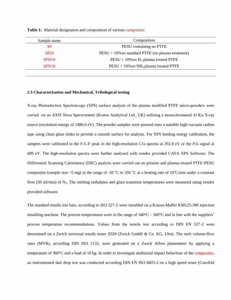
Table 1: Material designation and composition of various composites
Sample name Composition
S0 PESU containing no PTFE
SP10 PESU + 10%wt standard PTFE (no plasma treatment)
SPH10 PESU + 10%wt H2 plasma treated PTFE
SPN10 PESU + 10%wt NH3 plasma treated PTFE
2.3 Characterisation and Mechanical, Tribological testing
X-ray Photoelectron Spectroscopy (XPS) surface analysis of the plasma modified PTFE micro-powders were
carried on an AXIS Nova Spectrometer (Kratos Analytical Ltd., UK) utilising a monochromated Al Kα X-ray
source (excitation energy of 1486.6 eV). The powder samples were pressed onto a suitable high-vacuum carbon
tape using clean glass slides to provide a smooth surface for analysis. For XPS binding energy calibration, the
samples were calibrated to the F-C-F peak in the high-resolution C1s spectra at 292.8 eV or the F1s signal at
689 eV. The high-resolution spectra were further analysed with vendor provided CASA XPS Software. The
Differential Scanning Calorimetry (DSC) analysis were carried out on pristine and plasma treated PTFE-PESU
composites (sample size ~5 mg) in the range of -50 oC to 350
oC at a heating rate of 10
oC/min under a constant
flow (50 ml/min) of N2. The melting enthalpies and glass transition temperatures were measured using vendor
provided software.
The standard tensile test bars, according to ISO 527-2 were moulded on a Krauss-Maffei KM125-390 injection
moulding machine. The process temperatures were in the range of 340°C – 360°C and in line with the suppliers’
process temperature recommendations. Values from the tensile test according to DIN EN 527-2 were
determined on a Zwick universal tensile tester Z020 (Zwick GmbH & Co. KG, Ulm). The melt volume-flow
rates (MVR), according DIN ISO 1133, were generated on a Zwick Aflow plastometer by applying a
temperature of 360°C and a load of 10 kg. In order to investigate multiaxial impact behaviour of the composites,
an instrumented dart drop test was conducted according DIN EN ISO 6603-2 on a high speed tester (Coesfeld
GmbH, Dortmund). The drop dart test is a method to measure the ability of materials to absorb energy before
fracture. The sample plates with the dimension 60 mm x 60 mm and a thickness of 2 mm for dart drop test were
again moulded using Krauss-Maffei KM125-390 injection moulding machine. During the test, a dart with a
diameter of 20 mm and a weight of 20.33 kg, equipped with a load cell, falls down the dart frame onto the 60
mm x 60 mm x 2 mm test plate, which is fixed pneumatically. The velocity of the falling dart is 4.4 m/sec and
causes either plastic or elastic deformation (dependent on the material properties) eventually leading to the
fracture of the specimen. The attached load cell measures the maximum force (Fm) recorded during the impact
which is then used to calculate the correlated energy uptake [28]. The energy absorption is represented by the
integral of the area under the force-displacement curve [29]. From the generated data, a force time diagram can
be calculated and the maximum energy (Em) can be obtained.
The friction and wear data were obtained on a WAZAU tribometer TRM 1000 (Wazau GmbH, Berlin), by
applying a load of 3 N/mm2 and a sliding velocity of 0.5 m/second for the sliding distance of 14,000 meters.
The test pins were milled from tensile test bars in a radius of 1.7 mm and a length of 10 mm. In order to
examine also influence of the injection molded surface in the run in phase, the pins were cut from the end of the
test bar, in the opposite of the injection gate. All specimen were cleaned with ethanol before testing. The pin
were then put in a carrier which was pressed onto the rotating steel disc of 100 C6 steel, having a surface
roughness of Rz 2. The dynamic coefficient of friction was recorded continously and reported at the start of the
test, at the end of the run-in phase (at 2,000 meters) and subsequently at 6,000, 10,000 and 14,000 meters.
The specific wear rate k was calculated according following equation:
𝑘 =𝑊𝑉 [mm3]
𝐹N𝑠 [𝑁𝑚]
where WV is the volume loss of material calculated by the removed material. The removed material was
calculated (in µm) by the vertical displacement of the pin carrier, multiplied by the area. FN is the normal load
and s is the sliding disctance. All friction and wear tests were conducted in triplicate and the reported values are
the average of three measurments.
3 Results and discussion
3.1 XPS analysis of NH3 and H2 plasma treatment on PTFE micro powders
Figure 1(a) shows the wide energy survey spectra (WESS) for pristine and plasma treated samples. For all the
samples, only C, F and N/O peaks were observed indicative of the purity of the plasma treatment process.
Figure 1(b) shows the changes observed in the high resolution C1s spectra for plasma treated PTFE samples as
compared to the pristine PTFE. The treatment of PTFE powder samples with H2 as the process gas, led mainly
to the attachment of hydrogen and oxygen moieties. A small increase in the O/C ratio was also observed which
can be attributed to the oxygen groups getting attached simultaneously during/after the defluorination process.
These oxygen functional groups correspond to the components at 287.7 and 290.0 eV, which are assigned to C-
O and C=O bonds, respectively (Figure 1(c)). The oxygen is coming from the air after the removal of the
samples from the plasma device. Inagaki et al. have ascribed these peak positions in H2 treated PTFE surfaces to
O-CH-CFn, CHF and O=C-CFn, CHF-CFn groups, respectively [15]. In table 2, it can be clearly observed that
the F/C ratio, of PTFE H2 of 1.30 is much lower than that of pristine PTFE (F/C ratio of 1.86). According to
Vandencasteele [21], the small peak at 294 eV, at sample PTFE H2 can be attributed to CF3 components,
produced via chain scission. The peak with the binding energy of 292.2 eV can be assigned to (-CF2-) bond and
shows a narrow full width at half-maxima (FWHM) of 1.45 eV. Upon plasma functionalisation, an increase in
the FWHM of this peak can be observed (1.66 eV for H2/PTFE and 1.78 eV for NH3/PTFE) which can be
attributed to the formation of new functional groups. [30]. As observed in Figure 1(d), a further peak at approx.
285 eV, ascribed to adventitious –C-Hx- moieties is also observed [26,27]. The C1s envelope of NH3 plasma
treated samples exhibits a considerable increase in the component at 285 eV, and can be ascribed to the
formation of –C–C– and –C–Hx moieties. Peaks located at 286.0, 288.2 and 291.9 eV can be ascribed to C-
O/C-N and C=O, respectively. We assume the oxygen moieties are attached when the samples are removed
from the plasma chamber into the ambient. As clearly observed in Table 2, both the H2 and NH3 plasma
treatments were successful in altering the surface of PTFE micro-powders. The results of higher defluorination
upon NH3 treatment versus H2 treatment is in accordance with results reported by Badey et al [31,32]. Lehmann
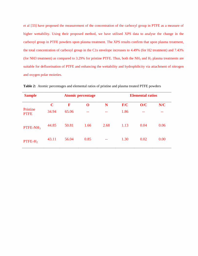
et al [33] have proposed the measurement of the concentration of the carboxyl group in PTFE as a measure of
higher wettability. Using their proposed method, we have utilised XPS data to analyse the change in the
carboxyl group in PTFE powders upon plasma treatment. The XPS results confirm that upon plasma treatment,
the total concentration of carboxyl group in the C1s envelope increases to 4.49% (for H2 treatment) and 7.43%
(for NH3 treatment) as compared to 3.29% for pristine PTFE. Thus, both the NH3 and H2 plasma treatments are
suitable for defluorination of PTFE and enhancing the wettability and hydrophilicity via attachment of nitrogen
and oxygen polar moieties.
Table 2: Atomic percentages and elemental ratios of pristine and plasma treated PTFE powders
Sample
Atomic percentage
Elemental ratios
C F O N F/C O/C N/C
Pristine
PTFE 34.94 65.06 -- -- 1.86 -- --
PTFE-NH3 44.85 50.81 1.66 2.68 1.13 0.04 0.06
PTFE-H2 43.11 56.04 0.85 -- 1.30 0.02 0.00
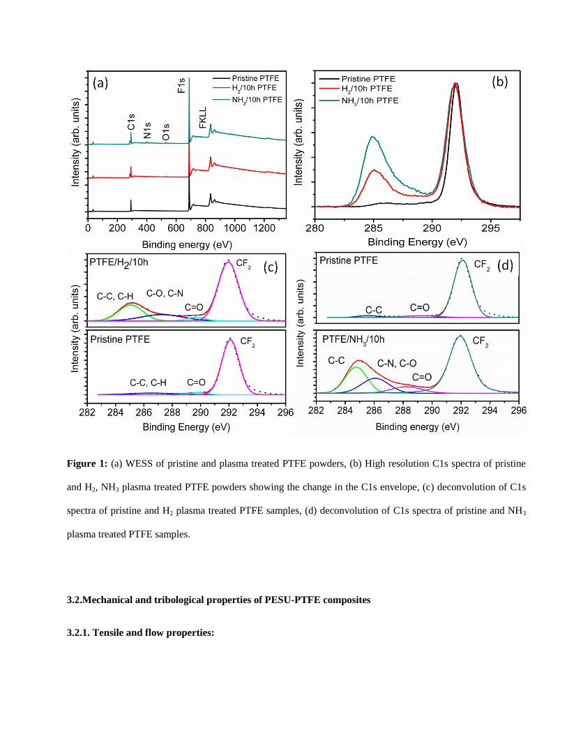
Figure 1: (a) WESS of pristine and plasma treated PTFE powders, (b) High resolution C1s spectra of pristine
and H2, NH3 plasma treated PTFE powders showing the change in the C1s envelope, (c) deconvolution of C1s
spectra of pristine and H2 plasma treated PTFE samples, (d) deconvolution of C1s spectra of pristine and NH3
plasma treated PTFE samples.
3.2.Mechanical and tribological properties of PESU-PTFE composites
3.2.1. Tensile and flow properties:
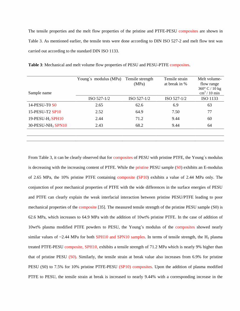
The tensile properties and the melt flow properties of the pristine and PTFE-PESU composites are shown in
Table 3. As mentioned earlier, the tensile tests were done according to DIN ISO 527-2 and melt flow test was
carried out according to the standard DIN ISO 1133.
Table 3: Mechanical and melt volume flow properties of PESU and PESU-PTFE composites.
Sample name
Young´s modulus (MPa) Tensile strength
(MPa)
Tensile strain
at break in %
Melt volume-
flow range 360° C / 10 kg
cm3 / 10 min
ISO 527-1/2 ISO 527-1/2 ISO 527-1/2 ISO 1133
14-PESU-T0 S0 2.65 62.6 6.9 63
15-PESU-T2 SP10 2.52 64.9 7.50 77
19-PESU-H2 SPH10 2.44 71.2 9.44 60
30-PESU-NH3 SPN10 2.43 68.2 9.44 64
From Table 3, it can be clearly observed that for composites of PESU with pristine PTFE, the Young´s modulus
is decreasing with the increasing content of PTFE. While the pristine PESU sample (S0) exhibits an E-modulus
of 2.65 MPa, the 10% pristine PTFE containing composite (SP10) exhibits a value of 2.44 MPa only. The
conjunction of poor mechanical properties of PTFE with the wide differences in the surface energies of PESU
and PTFE can clearly explain the weak interfacial interaction between pristine PESU/PTFE leading to poor
mechanical properties of the composite [35]. The measured tensile strength of the pristine PESU sample (S0) is
62.6 MPa, which increases to 64.9 MPa with the addition of 10wt% pristine PTFE. In the case of addition of
10wt% plasma modified PTFE powders to PESU, the Young’s modulus of the composites showed nearly
similar values of ~2.44 MPa for both SPH10 and SPN10 samples. In terms of tensile strength, the H2 plasma
treated PTFE-PESU composite, SPH10, exhibits a tensile strength of 71.2 MPa which is nearly 9% higher than
that of pristine PESU (S0). Similarly, the tensile strain at break value also increases from 6.9% for pristine
PESU (S0) to 7.5% for 10% pristine PTFE-PESU (SP10) composites. Upon the addition of plasma modified
PTFE to PESU, the tensile strain at break is increased to nearly 9.44% with a corresponding increase in the
tensile strength. According to Pukanszky et al, the higher tensile values can be attributed to the improved
interfacial interaction between the plasma modified PTFE and PESU matrix, induced due to the incorporation of
functional groups [34]. The decrease of Young’s modulus of the composite containing 10 % PTFE modification
is nearly similar for standard PTFE or plasma altered PTFE. So the plasma treatment of the PTFE modification
has just minor influence on the Young’s modulus.
For pristine PTFE-PESU composite, the melt flow values (see Table 3) increase with an increase in the PTFE
content. The standard PESU sample (S0) offers volume flow rates of value of 63 cm3/10 min, whereas the
benchmark sample SP10 containing 10% of pristine PTFE exhibits a value of 80 cm3/10 min. The PTFE micro-
powders are well known additives for improving the melt flow properties of thermoplastic resins and thus the
obtained results for pristine PTFE addition are in line with the expected behaviour [11]. However, with the
addition of the plasma modified PTFE powders to PESU matrix, the flow behaviour shows slightly anomalous
behaviour with a reduction in the flow rates to values (60-64 cm3/10 min) which are quite similar to the pristine
PESU (63 cm3/10 min). This may be attributed to an increased interaction between the plasma treated PTFE
particles and PESU matrix which limits the segmental movement of the PESU chains thereby enhancing the
viscosity of the composite.
3.2.2. Impact behaviour:
Figure 2 shows the force-time diagram for all the samples in the dart drop test. From the shape of the curve of
pristine PESU, sample S0, it can be observed that the pristine PESU shows ductile-brittle fracture behaviour. As
observed clearly from Figure 2, the incorporation of pristine PTFE generally lowers the maximum force (Fm)
and energy absorption (Em) values significantly. In fact, pristine PESU sample S0 absorbs a maximum force
(Fm) of 5.6 kN and an energy at maximum force (Em) of 51.6 J; whereas the addition of 10wt% pristine PTFE
(SP10) reduces these values of 0.96 kN and 2.63 J, which are only 17% and 5% of the original values,
respectively.
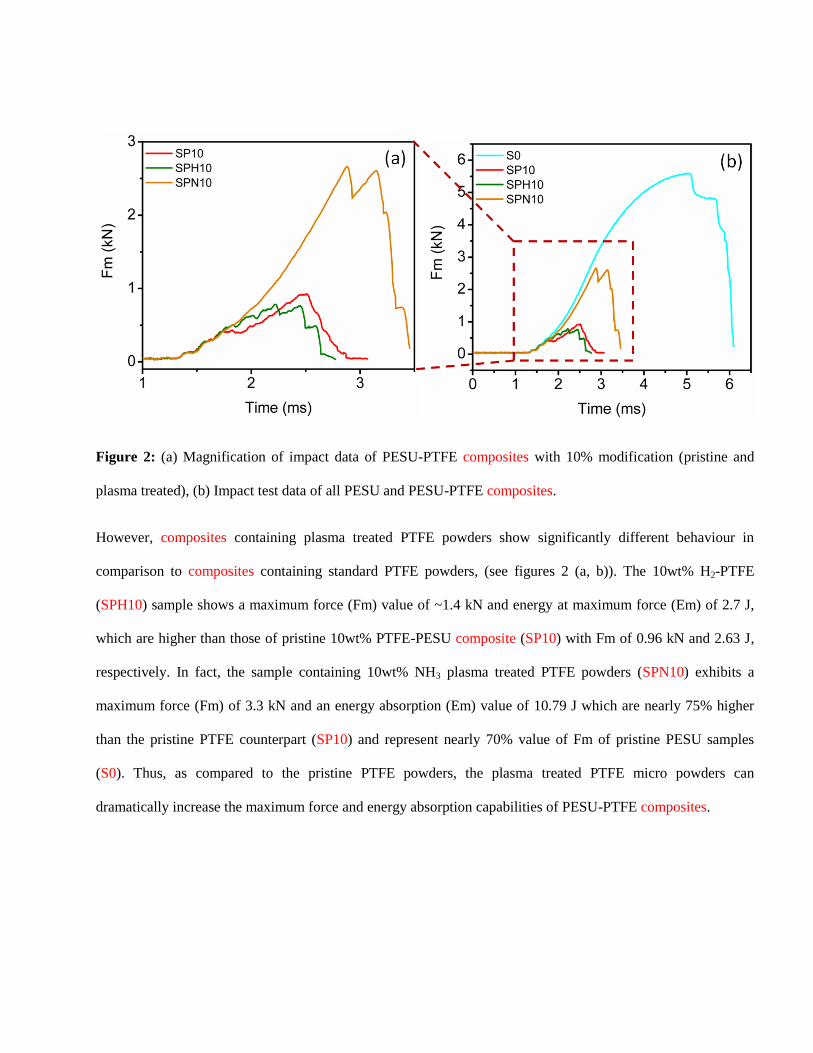
Figure 2: (a) Magnification of impact data of PESU-PTFE composites with 10% modification (pristine and
plasma treated), (b) Impact test data of all PESU and PESU-PTFE composites.
However, composites containing plasma treated PTFE powders show significantly different behaviour in
comparison to composites containing standard PTFE powders, (see figures 2 (a, b)). The 10wt% H2-PTFE
(SPH10) sample shows a maximum force (Fm) value of ~1.4 kN and energy at maximum force (Em) of 2.7 J,
which are higher than those of pristine 10wt% PTFE-PESU composite (SP10) with Fm of 0.96 kN and 2.63 J,
respectively. In fact, the sample containing 10wt% NH3 plasma treated PTFE powders (SPN10) exhibits a
maximum force (Fm) of 3.3 kN and an energy absorption (Em) value of 10.79 J which are nearly 75% higher
than the pristine PTFE counterpart (SP10) and represent nearly 70% value of Fm of pristine PESU samples
(S0). Thus, as compared to the pristine PTFE powders, the plasma treated PTFE micro powders can
dramatically increase the maximum force and energy absorption capabilities of PESU-PTFE composites.
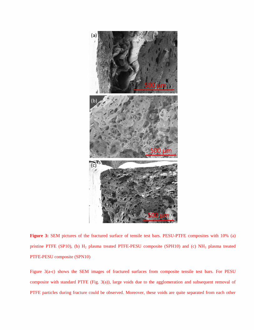
Figure 3: SEM pictures of the fractured surface of tensile test bars. PESU-PTFE composites with 10% (a)
pristine PTFE (SP10), (b) H2 plasma treated PTFE-PESU composite (SPH10) and (c) NH3 plasma treated
PTFE-PESU composite (SPN10)
Figure 3(a-c) shows the SEM images of fractured surfaces from composite tensile test bars. For PESU
composite with standard PTFE (Fig. 3(a)), large voids due to the agglomeration and subsequent removal of
PTFE particles during fracture could be observed. Moreover, these voids are quite separated from each other
suggesting at the lack of interaction between the PTFE powder and PESU matrix. Due to the large differences
in the surface energies of PESU and PTFE, the injection moulding skin largely seemed to be consisting of
PESU only with the PTFE being present on the inside of the fracture surface. For the composite samples
containing the plasma treated PTFE (H2 treated (Fig. 3(b)) and NH3 treated (Fig. 3(c))), the fracture surface was
significantly different from pristine PTFE-PESU compounds. Especially for the NH3 treated samples, the
distribution of the PTFE particles was much more uniform across the PESU matrix. The uniform distribution of
PTFE in conjunction with the smaller size of the voids suggests that the incorporation of functional groups
enables a better interface interaction between the PESU matrix and the PTFE modification and is therefore
beneficial for the mechanical properties.
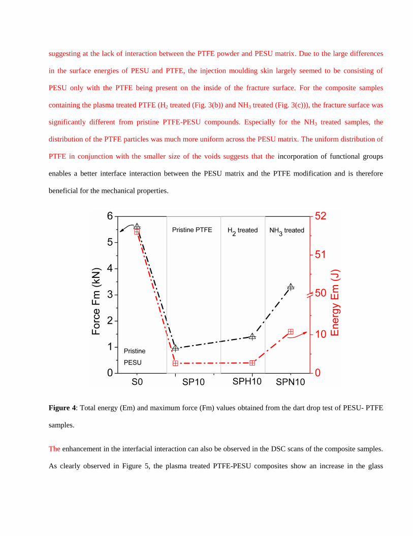
Figure 4: Total energy (Em) and maximum force (Fm) values obtained from the dart drop test of PESU- PTFE
samples.
The enhancement in the interfacial interaction can also be observed in the DSC scans of the composite samples.
As clearly observed in Figure 5, the plasma treated PTFE-PESU composites show an increase in the glass
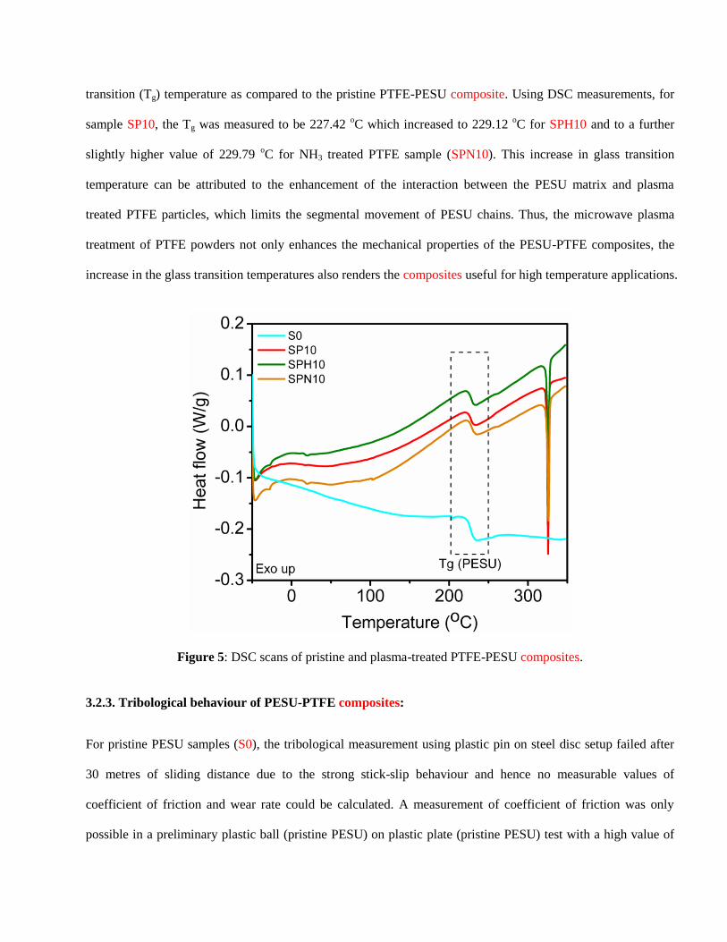
transition (Tg) temperature as compared to the pristine PTFE-PESU composite. Using DSC measurements, for
sample SP10, the Tg was measured to be 227.42 oC which increased to 229.12
oC for SPH10 and to a further
slightly higher value of 229.79 oC for NH3 treated PTFE sample (SPN10). This increase in glass transition
temperature can be attributed to the enhancement of the interaction between the PESU matrix and plasma
treated PTFE particles, which limits the segmental movement of PESU chains. Thus, the microwave plasma
treatment of PTFE powders not only enhances the mechanical properties of the PESU-PTFE composites, the
increase in the glass transition temperatures also renders the composites useful for high temperature applications.
Figure 5: DSC scans of pristine and plasma-treated PTFE-PESU composites.
3.2.3. Tribological behaviour of PESU-PTFE composites:
For pristine PESU samples (S0), the tribological measurement using plastic pin on steel disc setup failed after
30 metres of sliding distance due to the strong stick-slip behaviour and hence no measurable values of
coefficient of friction and wear rate could be calculated. A measurement of coefficient of friction was only
possible in a preliminary plastic ball (pristine PESU) on plastic plate (pristine PESU) test with a high value of
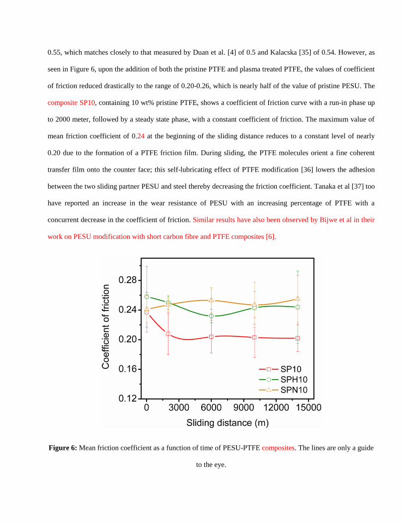
0.55, which matches closely to that measured by Duan et al. [4] of 0.5 and Kalacska [35] of 0.54. However, as
seen in Figure 6, upon the addition of both the pristine PTFE and plasma treated PTFE, the values of coefficient
of friction reduced drastically to the range of 0.20-0.26, which is nearly half of the value of pristine PESU. The
composite SP10, containing 10 wt% pristine PTFE, shows a coefficient of friction curve with a run-in phase up
to 2000 meter, followed by a steady state phase, with a constant coefficient of friction. The maximum value of
mean friction coefficient of 0.24 at the beginning of the sliding distance reduces to a constant level of nearly
0.20 due to the formation of a PTFE friction film. During sliding, the PTFE molecules orient a fine coherent
transfer film onto the counter face; this self-lubricating effect of PTFE modification [36] lowers the adhesion
between the two sliding partner PESU and steel thereby decreasing the friction coefficient. Tanaka et al [37] too
have reported an increase in the wear resistance of PESU with an increasing percentage of PTFE with a
concurrent decrease in the coefficient of friction. Similar results have also been observed by Bijwe et al in their
work on PESU modification with short carbon fibre and PTFE composites [6].
Figure 6: Mean friction coefficient as a function of time of PESU-PTFE composites. The lines are only a guide
to the eye.
As compared to the addition of pristine PTFE, the effect of addition of plasma modified PTFE to PESU showed
slightly higher mean friction coefficients than the benchmark pristine PTFE sample (SP10). Due to the presence
of the functional groups on the plasma treated polymer, the formation of thin transfer film of PTFE was
possibly hindered thereby leading to an increase in the observed CoF values [38]. As seen in Figure 6, while,
the coefficient of friction of the H2 treated PTFE-PESU composite (19-PESU-H2) is decreasing in the run-in
phase from 0.260 to 0.250 and further down to 0.23, but increases to 0.24 again after the half of the total sliding
distance; the coefficient of friction of the composite containing the NH3 treated PTFE (30-PESU-NH3), is
increasing over the whole of measured sliding distance from 0.240 up to 0.255. The change in the chemical
PTFE structure with significant defluorination and the attachment of oxygen and nitrogen moieties in the side
chain, renders the PTFE to have a higher interaction with the PESU and potentially the steel counter surface,
which causes slightly higher coefficient of friction and a potential higher tendency of stick-slip behaviour. The
transfer of material from the polymer composite to the metal surface is governed due to the adhesion between
the two materials. Bahadur [39] has ascribed this to the cohesive bonding between PTFE end caps or other free
radicals and the metallic surface. The plasma treatment of PTFE even increases this effect by means of
incorporation of functional groups, which enables the composite to form more inter molecular bonds to the
metal surface and therefore has an influence on the creation of the friction film. In general the adhesion between
the polymer and the metal surface during sliding contributes to shear in the contact region. This causes small
particles in the contact area which forms the friction film during slinding. Sharp asperities of the metal surface
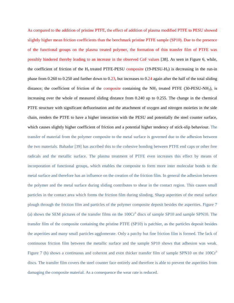
plough through the friction film and particles of the polymer composite deposit besides the asperities. Figure 7
(a) shows the SEM pictures of the transfer films on the 100Cr6 discs of sample SP10 and sample SPN10. The
transfer film of the composite containing the pristine PTFE (SP10) is patchier, as the particles deposit besides
the asperities and many small particles agglomerate. Only a patchy but fine friction film is formed. The lack of
continuous friction film between the metallic surface and the sample SP10 shows that adhesion was weak.
Figure 7 (b) shows a continuous and coherent and even thicker transfer film of sample SPN10 on the 100Cr6
discs. The transfer film covers the steel counter face entirely and therefore is able to prevent the asperities from
damaging the composite material. As a consequence the wear rate is reduced.
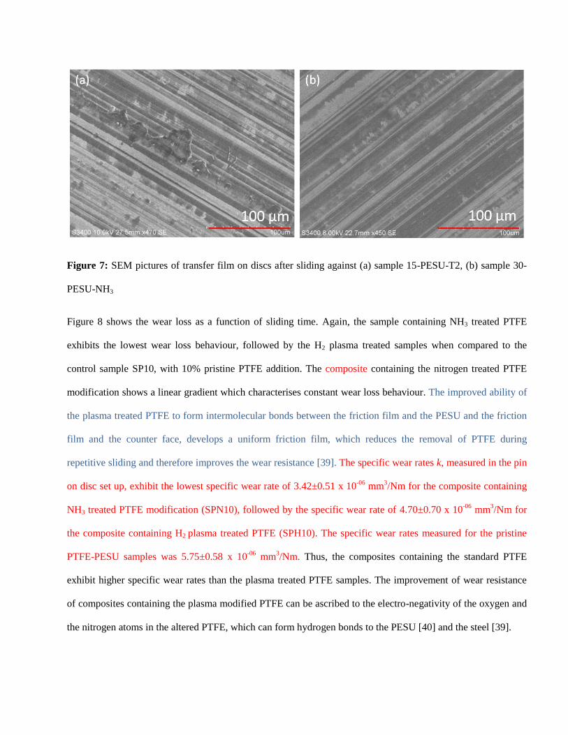
Figure 7: SEM pictures of transfer film on discs after sliding against (a) sample 15-PESU-T2, (b) sample 30-
PESU-NH3
Figure 8 shows the wear loss as a function of sliding time. Again, the sample containing NH3 treated PTFE
exhibits the lowest wear loss behaviour, followed by the H2 plasma treated samples when compared to the
control sample SP10, with 10% pristine PTFE addition. The composite containing the nitrogen treated PTFE
modification shows a linear gradient which characterises constant wear loss behaviour. The improved ability of
the plasma treated PTFE to form intermolecular bonds between the friction film and the PESU and the friction
film and the counter face, develops a uniform friction film, which reduces the removal of PTFE during
repetitive sliding and therefore improves the wear resistance [39]. The specific wear rates k, measured in the pin
on disc set up, exhibit the lowest specific wear rate of 3.42±0.51 x 10-06
mm3/Nm for the composite containing
NH3 treated PTFE modification (SPN10), followed by the specific wear rate of 4.70±0.70 x 10-06
mm3/Nm for
the composite containing H2 plasma treated PTFE (SPH10). The specific wear rates measured for the pristine
PTFE-PESU samples was 5.75±0.58 x 10-06
mm3/Nm. Thus, the composites containing the standard PTFE
exhibit higher specific wear rates than the plasma treated PTFE samples. The improvement of wear resistance
of composites containing the plasma modified PTFE can be ascribed to the electro-negativity of the oxygen and
the nitrogen atoms in the altered PTFE, which can form hydrogen bonds to the PESU [40] and the steel [39].
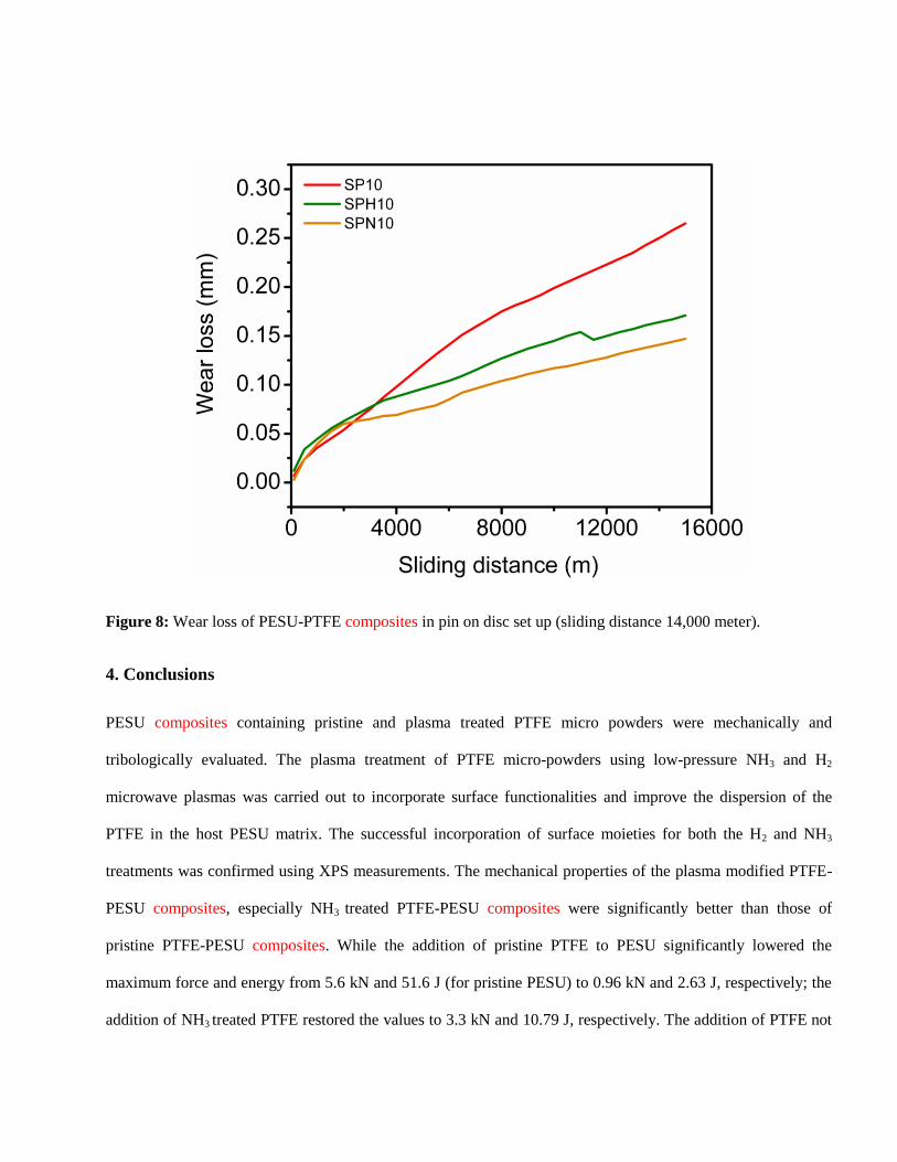
Figure 8: Wear loss of PESU-PTFE composites in pin on disc set up (sliding distance 14,000 meter).
4. Conclusions
PESU composites containing pristine and plasma treated PTFE micro powders were mechanically and
tribologically evaluated. The plasma treatment of PTFE micro-powders using low-pressure NH3 and H2
microwave plasmas was carried out to incorporate surface functionalities and improve the dispersion of the
PTFE in the host PESU matrix. The successful incorporation of surface moieties for both the H2 and NH3
treatments was confirmed using XPS measurements. The mechanical properties of the plasma modified PTFE-
PESU composites, especially NH3 treated PTFE-PESU composites were significantly better than those of
pristine PTFE-PESU composites. While the addition of pristine PTFE to PESU significantly lowered the
maximum force and energy from 5.6 kN and 51.6 J (for pristine PESU) to 0.96 kN and 2.63 J, respectively; the
addition of NH3 treated PTFE restored the values to 3.3 kN and 10.79 J, respectively. The addition of PTFE not
only eliminated the strong slip-stick behaviour of PESU but also reduced the friction and wear constants
significantly. While, pristine PESU showed CoF values of over 0.55, the addition of PTFE reduced these values
in half to approximately 0.20-0.26. As compared to pristine PTFE, the plasma treated PTFE-PESU composites
showed slightly higher CoF values which can be attributed to the defluorination and interaction of counter
surface film to both the PESU and PTFE surfaces. Nevertheless, the wear rates (3.42 x 10-06
mm3/Nm) for NH3-
treated PTFE-PESU composites was nearly half of those of pristine PTFE-PESU composites (5.75 x 10-06
mm3/Nm) and significantly lower than that of pristine PESU. Also, the gradient of the wear loss curve of
samples containing plasma treated PTFE is smaller and for NH3 treated PTFE more constant than that of
pristine PTFE-PESU composites at same loadings. The friction film of PESU containing NH3 treated PTFE is
more uniform, providing an improved wear resistance. Thus, the incorporation of functional groups via plasma
treatment without altering the bulk properties of the materials is an effective and efficient route for the
dispersion of solid lubricants like PTFE for enhancement of mechanical and tribological properties. Further
investigation need to be done to obtain the optimum plasma treatment parameters in terms of process gas and
treatment time. Furthermore, different tribological investigations of different loads and sliding velocities or
different test set-ups such as block on ring test method need to be carried out for a more detailed tribological
characterization including XPS characterisation of counter-surfaces for chemical evaluation of friction films.
Acknowledgements
The authors would like to acknowledge BASF SE (Polyethersulfone Ultrason E 2010), Sitraplas GmbH
(supplying Dyneon™ TF9201Z micro-powder) for providing the materials free of charge and Diener Electronic
GmbH + Co. KG for performing the plasma treatments on PTFE powders. We would further like to thank the
National EPSRC XPS User's Service (NEXUS) at Newcastle University, an EPSRC Mid-Range Facility, for the
carrying out X-ray photoelectron measurements. Very special thanks to Sitraplas GmbH for the use of their
facilities for compounding of the materials. The authors gratefully acknowledge the help from Mrs. Regina
Straessle and Mr. Fabian Meier from the KATZ Traning and Technology Center in Aarau, Switzerland for
tribological measurements.
REFERENCES: REFERENCES
[1] Duan Y, Cong P, Liu X, Li T. Comparative Study of Tribological Properties of Polyphenylene Sulfide (PPS),
Polyethersulfone (PES), and Polysulfone (PSU). J. of Macromolecular Sc., Part B 2009;48(2):269–81.
[2] R. Künkel. Auswahl und optimierung von Kunststoffen für tribologisch beanspruchte Systeme. Erlangen:
Univ., Lehrstuhl für Kunststofftechnik, 2005.
[3] Atkins AG, Omar MK, Lancaster JK. Wear of polymers. J Mater Sci Lett 1984;3(9):779–82.
[4] Duan Y, Cong P, Liu X, Li T. Comparative Study of Tribological Properties of Polyphenylene Sulfide (PPS),
Polyethersulfone (PES), and Polysulfone (PSU). J. of Macromolecular Sc., Part B 2009;48(2):269–81.
[5] Duan Y, Cong P, Liu X, Li T. Friction and Wear of Polyphenylene Sulfide (PPS), Polyethersulfone (PES) and
Polysulfone (PSU) Under Different Cooling Conditions. J. of Macromolecular Sc., Part B 2009;48(3):604–
16.
[6] Bijwe J, Rajesh J, Jeyakumar A, Ghosh A, Tewari U. Influence of solid lubricants and fibre reinforcement
on wear behaviour of polyethersulphone. Tribology International 2000;33(10):697–706.
[7] Aurilia M, Sorrentino L, Sanguigno L, Iannace S. Nanofilled polyethersulfone as matrix for continuous
glass fibers composites: Mechanical properties and solvent resistance. Adv. Polym. Technol.
2010;29(3):146–60.
[8] Bijwe J, Awtade S, Satapathy BK, Ghosh A. Influence of Concentration of Aramid Fabric on Abrasive
Wear Performance of Polyethersulfone Composites. Tribology Letters 2004;17(2):187–94.
[9] Bijwe J, Sharma M. Nano and Micro PTFE for Surface Lubrication of Carbon Fabric Reinforced
Polyethersulphone Composites:19–39.
[10] Basavaraj E, Ramaraj B, Siddaramaiah. Investigations on the influence of polytetrafluoroethylene
powder as a filler on physico-mechanical and wear characteristics of nylon 66/graphite composites. High
Performance Polymers 2012;24(7):616–24.
[11] Ebnesajjad S, Morgan RA. Fluorinated Additives for Plastics:107–48.
[12] Li J. The Impact and Tribological Properties of PTFE Composites Filled with PA6. Journal of Thermoplastic
Composite Materials 2010;23(6):807–16.
[13] FRIEDRICH K, ZHANG Z, SCHLARB A. Effects of various fillers on the sliding wear of polymer composites.
Composites Science and Technology 2005;65(15-16):2329–43.
[14] Franke R, Lehmann D, Kunze K. Tribological behaviour of new chemically bonded PTFE polyamide
compounds. Wear 2007;262(3-4):242–52.
[15] Inagaki N, Tasaka S, Narushima K, Teranishi K. J. Appl. Polym. Sci.:340–8.
[16] Shojaei A, Gholamalipour S. Effect of chemical treatment of Teflon powder on the properties of
polyamide 66/Teflon composites prepared by melt mixing. Macromol. Res. 2011;19(6):613–21.
[17] Aderikha VN, Shapovalov VA. Mechanical and tribological behavior of PTFE–polyoxadiazole fiber
composites. Effect of filler treatment. Wear 2011;271(5-6):970–6.
[18] Khan MS, Franke R, Gohs U, Lehmann D, Heinrich G. Friction and wear behaviour of electron beam
modified PTFE filled EPDM compounds. Wear 2009;266(1-2):175–83.
[19] Klüpfel B, Lehmann D. Functionalization of irradiated PTFE micropowder with methacryl- or hydroxy
groups for chemical coupling of PTFE with different matrix polymers. J. Appl. Polym. Sci.
2006;101(5):2819–24.
[20] Diener electronic GmbH + Co. KG. Plasma Technology. [May 25, 2013]; Available from:
http://www.plasmasurfacetechnology.eu/media/Plasmatechnik_en_web.pdf.
[21] Vandencasteele N, Reniers F. Surface characterization of plasma-treated PTFE surfaces: an OES, XPS and
contact angle study. Surf. Interface Anal. 2004;36(8):1027–31.
[22] Caro JC, Lappan U, Lunkwitz K. Insertion of sulfur-containing functional groups into
polytetrafluoroethylene (PTFE) by low pressure plasma treatment. Surface and Coatings Technology
1999;116-119:792–5.
[23] Dufour T, Hubert J, Viville P, Duluard CY, Desbief S, Lazzaroni R, Reniers F. PTFE Surface Etching in the
Post-discharge of a Scanning RF Plasma Torch: Evidence of Ejected Fluorinated Species. Plasma
Processes Polym. 2012;9(8):820–9.
[24] Jie-Rong C, Wakida T. Studies on the surface free energy and surface structure of PTFE film treated with
low temperature plasma. J. Appl. Polym. Sci. 1997;63(13):1733–9.
[25] Liu C, Wu J, Ren L, Tong J, Li J, Cui N, Brown N, Meenan B. Comparative study on the effect of RF and
DBD plasma treatment on PTFE surface modification. Materials Chemistry and Physics 2004;85(2-
3):340–6.
[26] Wilson DJ, Williams RL, Pond RC. Plasma modification of PTFE surfaces. Part II: Plasma-treated surfaces
following storage in air or PBS. Surf. Interface Anal. 2001;31(5):397–408.
[27] Wilson DJ, Williams RL, Pond RC. Plasma modification of PTFE surfaces. Part I: Surfaces immediately
following plasma treatment. Surf. Interface Anal. 2001;31(5):385–96.
[28] Soever A, Hopf M, Frormann L. Polymer Testing:703–8.
[29] Liu TM, Baker WE. Instrumented dart impact evaluation of linear low density polyethylene at controlled
impact energy. Polym. Eng. Sci. 1991;31(10):753–63.
[30] Beamson G, Briggs D. High resolution XPS of organic polymers: The Scienta ESCA300 database.
Chichester [England], New York: Wiley, 1992.
[31] Badey JP, Espuche E, Sage D, Chabert B, Jugnet Y, Batier C, Duc TM. A comparative study of the effects
of ammonia and hydrogen plasma downstream treatment on the surface modification of
polytetrafluoroethylene. Polymer 1996;37(8):1377–86.
[32] Badey JP, Urbaczewski-Espuche E, Jugnet Y, Sage D, Duc TM, Chabert B. Surface modification of
polytetrafluoroethylene by microwave plasma downstream treatment. Polymer 1994;35(12):2472–9.
[33] Khan MS. Structure-property effects on mechanical, friction and wear properties of electron modified
PTFE filled EPDM composite. expresspolymlett 2008;3(1):39–48.
[34] Pukanszky B and Fekete E. Adhesion and surface modification 1999;139:109–53.
[35] Kalacska G. An engineering approach to dry friction behaviour of numerous engineering plastics with
respect to the mechanical properties. expresspolymlett 2012;7(2):199–210.
[36] K. Friedrich (ed.). Friction and wear of polymer composites. Amsterdam, The Netherlands: Elsevier
Science Publishers, B. V., Amsterdam, 1986.
[37] Tanaka K, Yamada Y, Ueda S. Effect of temperature on the friction and wear of heat-resistant polymer-
based composites. J. Synth. Lubr. 1992;8(4):281–94.
[38] Sinha SK. Polymer tribology. London: Imperial College Press, 2009.
[39] Bahadur S. The development of transfer layers and their role in polymer tribology. Wear 2000;245(1-
2):92–9.
[40] Hüttinger KJ, Krekel G, Zielke U. Evidence for chemical bond formation between surface treated carbon
fibres and high temperature thermoplastics. J. Appl. Polym. Sci. 1994;51(4):737–42.