Embed Size (px)
Citation preview
CHINESE JOURNAL OF MECHANICAL ENGINEERING Vol. 28,aNo. 2,a2015
·363·
DOI: 10.3901/CJME.2015.0108.009, available online at www.springerlink.com; www.cjmenet.com; www.cjme.com.cn
Influence of Friction Drive Lift Gears Construction on the Length of Braking Distance
LONKWIC Poul*
Lublin Factory of Passenger Lifts Lift Service S. A. Lublin, Roztoczestreet 6, 20-722 Lublin, Poland
Received July 8, 2014; revised January 6, 2015; accepted January 8, 2015
Abstract: The friction drive elevators the influence of the braking distance has very high significance to meet certain safety regulations
and comfort. During the emergency braking the delay for the system a frame and a cabin should be within the range from 0.2 to 9.81 m/s2.
However, there are no specialist literatures regarding the issues connected with emergency braking of elevating devices either. The results
of the own empirical research work are presented regarding the influence of design changes on the working parameters of the friction drive
elevator gears. ASG100, KB160, PP16, PR2000UD and CHP2000 types of safety progressive gears are analyzed. ASG100, KB160, PP16,
PR2000UD type progressive gears are already produced by European manufacturers. CHP2000 type gears are established as the
alternative option for the already existing solutions. The unique cam system has been used in the CHP 2000 gears. The cam leverage gives
the chance to unblock, in a very easy way, the clamed gears after braking. Thus, it is a key aspect to perform laboratory tests over the
braking process of a newly created solution. The proper value of the braking distance has a significant influence on the value of delay in
terms of binding standards. The influence of loading on the effective braking distance and the value of the falling elevator cabin speed are
analyzed and the results are presented. The results presented are interesting from lift devices operation and a new model of CHP 2000
progressive gear point of view.
Keywords: lift gears, friction drive, progressive safety gears, braking distance, emergency braking
1 Introduction
The first safety gears were invented by Elisha Graves Otis in 1852. The American engineer invented an automatic safety brake thanks to which the elevators as transportation means became practical and safe transportation means. Since that time, the progressive safety gears became the subject of development in many companies responsible for manufacture of that range of products. With development of elevators branch and optimization of those devices in terms of dimensions, at the beginning the safety gears were used as instantaneous safety gears. Over time, the gears construction has been developed as well as progressive safety gears have been implemented thanks to which the loadings generated on the elements which lead the elevator cabin have been changed.
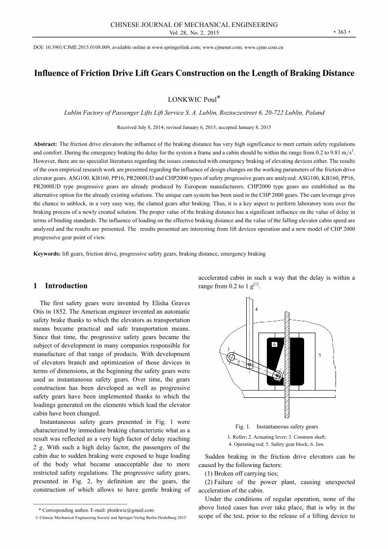
Instantaneous safety gears presented in Fig. 1 were characterized by immediate braking characteristic what as a result was reflected as a very high factor of delay reaching 2 g. With such a high delay factor, the passengers of the cabin due to sudden braking were exposed to huge loading of the body what became unacceptable due to more restricted safety regulations. The progressive safety gears, presented in Fig. 2, by definition are the gears, the construction of which allows to have gentle braking of
* Corresponding author. E-mail: [email protected]
© Chinese Mechanical Engineering Society and Springer-Verlag Berlin Heidelberg 2015
accelerated cabin in such a way that the delay is within a range from 0.2 to 1 g[1].
Fig. 1. Instantaneous safety gears
1. Roller; 2. Actuating lever; 3. Common shaft; 4. Operating rod; 5. Safety gear block; 6. Jaw.
Sudden braking in the friction drive elevators can be
caused by the following factors: (1) Broken off carrying ties; (2) Failure of the power plant, causing unexpected
acceleration of the cabin. Under the conditions of regular operation, none of the
above listed cases has ever take place, that is why in the scope of the test, prior to the release of a lifting device to
Y LONKWIC Poul: Influence of Friction Drive Lift Gears Construction on the Length of Braking Distance
·364·
operation, tests based on the provisions included in the standard para. 81.1 are performed.
Fig. 2. Progressive safety gears
Lots of publications touching the issues of friction drive elevators focus on different forms of supervision over the device operation. In the publication[2] present the way of description for acceleration of a freight lift by the application of a reduction method for the system which supervises the elevator work. In the publication[3] author focuses on increase of elevator speed brings about amplified vibrations of high-speed elevator. In order to reduce the horizontal vibrations of high-speed elevator, a new type of hydraulic active guide roller system based on fuzzy logic controller is developed. In the publication[4] the authors touch the problem connected with miscellaneous polyurethane materials used as a carriageable element of the elevator. Moreover, the publication presents what kind of influence different types of polyurethane have on the deformation of a slide roller during the elevating device downtime. In the publication[5] the problem of stresses and deformation of the hydraulic elevator frame structure during the sudden braking with the use of instantaneous gears has been presented. Obtained results have a significant influence on the safety coefficients of the elevator frame construction. Author in the publication[6] concentrated his research on the nonstationary, nonlinear dynamic interactions in slender continua deployed in high-rise vertical transportation systems. In the publication[7] the author presents new type progressive gears, the construction of which is based on the cam-built mechanism. Its operation depends on the complex pile of Belleville springs whereas the value of their tension depends on nominal load capacity of the elevating device. In the second publication[8] the authors present their own concept of innovative device for tightening the line of the speed limiter, the operation of which depends on the value of strength generated by the tightening spring with the use of which proper strength value of friction between the line and a wheel of the speed limiter is obtained. In the dissertation[9] the author touches the problem of the wear and tear of the friction drive elevator wheel with the use of an acoustic signal. In the publication[10] the authors use a
mathematical method employed in neural network for the elevator vibrations prediction. Moreover, many authors of publications[11–12] mention the issues connected with vibrations of carrying ropes as well as with modeling of elevating devices control in the operation conditions. Methodology of vibrations and prediction measurements constitutes in that case an important aspect of research over the proper operation of a device and undesirable consequences of vibrations in the device construction. The research over the efficiency evaluation of hydraulic braking system applied in hydraulic elevators is described in the publication[13]. Authors in the publications[14–16] presents new construction safety gears with new materials as composites which is made of a braking element safety gears. In the publication[17] author presents researches mostly on to how detected the break of elevator by using computer technique. Author the hardware design is focus on its framework. The software–part analyze the idea and computer the parameter of the break of elevator. The authors in the publications[18–23] presents their own work on modeling and analysis of phenomena relating to vibration and simulation of lifting equipment.
While analyzing specialist literature within research activities regarding mechanical side of elevating devices some kind of deficiency can be noticed referring to mathematical description of braking systems operation applied in the friction drive elevators.
2 Influence of Geometric Properties
on the Course of Braking Process The elevator braking process constitutes the sum of
actions coming one after the other as a result of the device operation. Thus, the position of speed limiting wheel in relation to its latch, the gears construction and the value of friction forces between the speed limiter wheel and the line influence the braking distance. In the presented compilation, the attention mainly has been paid to the construction of the gears taken into account. Therefore, the braking distance depends on Y1 distance which is covered by a braking roller starting from the beginning of braking process initiation to the place of the contact between the roller and the rail surface as well as in the further stage of the braking process depends on effective Y5 braking distance. The effective braking distance is understood as the distance during which the full contact between the roller and the rail surface takes place due to which the sign after braking remains. With respect to the above, the elevator braking distance can be reflected in the form of an empirical Eq. (1):
H 1 5 s ,L Y Y x= + - (1)
where Y1 is the path which is covered by the roller from the moment of braking process initiation(mm), Y5 is the distance which is covered by the roller from the moment of the elevator stoppage(mm), xs is deflection of the susceptible element which generates the reaction of braking(mm).
CHINESE JOURNAL OF MECHANICAL ENGINEERING
·365·
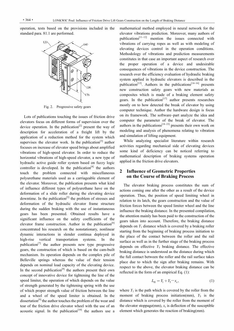
In Fig. 3 the diagram of the roller movement vectors for CHP2000 safety gear is presented. The change of the roller position in the gear frame is the result of the change in the elevator location connected with the speed limiter cable.
Fig. 3. Progressive safety gears CHP2000
with geometrical parameters
3 Characteristic of a Test Bench In order to perform tests regarding the influence of the
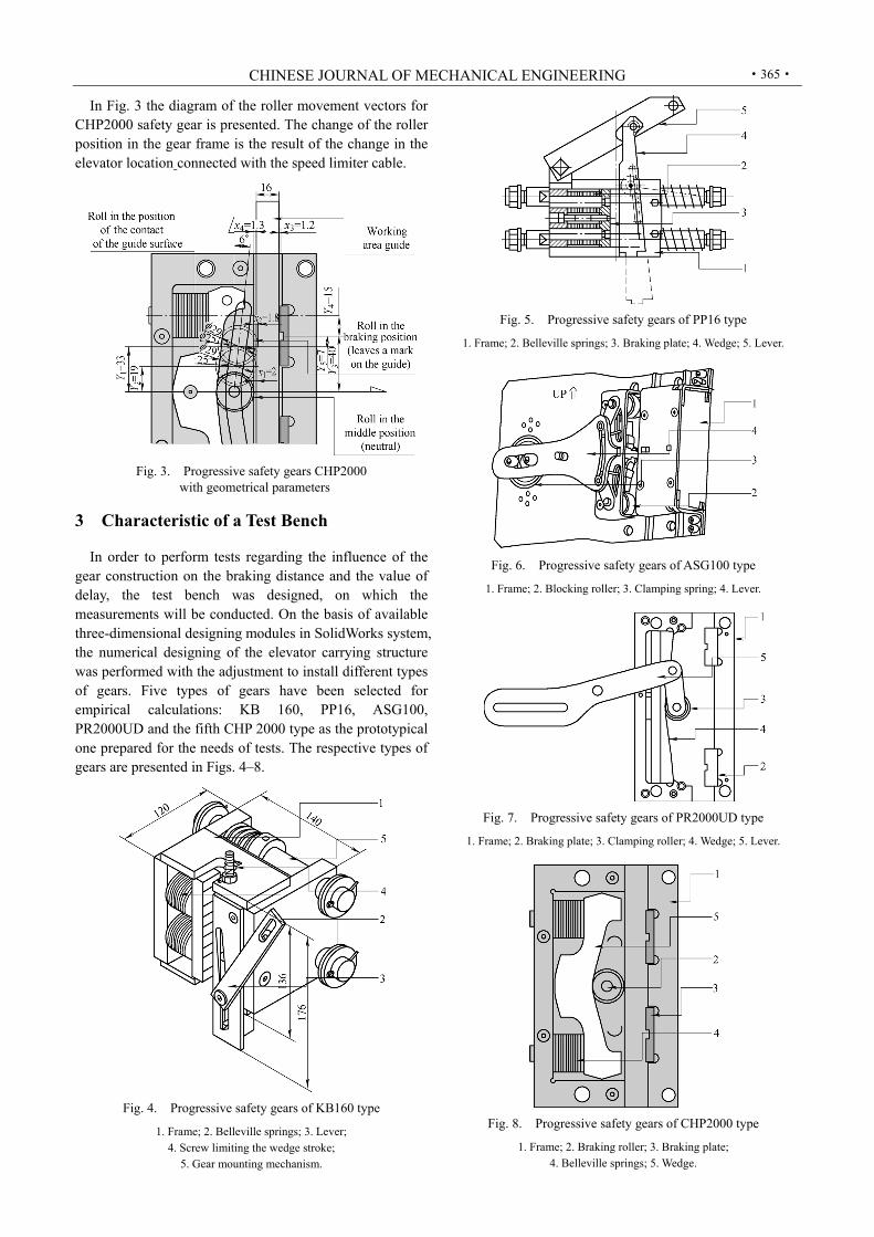
gear construction on the braking distance and the value of delay, the test bench was designed, on which the measurements will be conducted. On the basis of available three-dimensional designing modules in SolidWorks system, the numerical designing of the elevator carrying structure was performed with the adjustment to install different types of gears. Five types of gears have been selected for empirical calculations: KB 160, PP16, ASG100, PR2000UD and the fifth CHP 2000 type as the prototypical one prepared for the needs of tests. The respective types of gears are presented in Figs. 4–8.
Fig. 4. Progressive safety gears of KB160 type
1. Frame; 2. Belleville springs; 3. Lever; 4. Screw limiting the wedge stroke;
5. Gear mounting mechanism.
Fig. 5. Progressive safety gears of PP16 type
1. Frame; 2. Belleville springs; 3. Braking plate; 4. Wedge; 5. Lever.
Fig. 6. Progressive safety gears of ASG100 type
1. Frame; 2. Blocking roller; 3. Clamping spring; 4. Lever.
Fig. 7. Progressive safety gears of PR2000UD type
1. Frame; 2. Braking plate; 3. Clamping roller; 4. Wedge; 5. Lever.
Fig. 8. Progressive safety gears of CHP2000 type
1. Frame; 2. Braking roller; 3. Braking plate; 4. Belleville springs; 5. Wedge.
Y LONKWIC Poul: Influence of Friction Drive Lift Gears Construction on the Length of Braking Distance
·366·
4 Influence of the Geometrical Properties
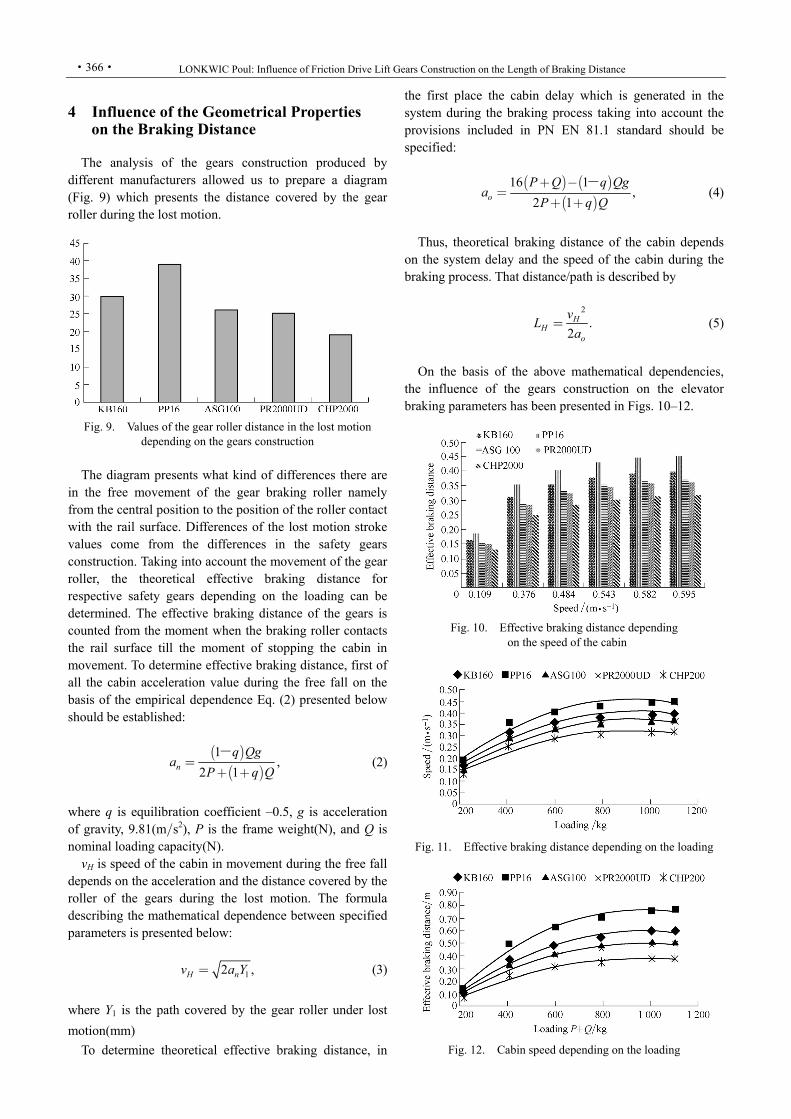
on the Braking Distance The analysis of the gears construction produced by
different manufacturers allowed us to prepare a diagram (Fig. 9) which presents the distance covered by the gear roller during the lost motion.
Fig. 9. Values of the gear roller distance in the lost motion
depending on the gears construction
The diagram presents what kind of differences there are
in the free movement of the gear braking roller namely from the central position to the position of the roller contact with the rail surface. Differences of the lost motion stroke values come from the differences in the safety gears construction. Taking into account the movement of the gear roller, the theoretical effective braking distance for respective safety gears depending on the loading can be determined. The effective braking distance of the gears is counted from the moment when the braking roller contacts the rail surface till the moment of stopping the cabin in movement. To determine effective braking distance, first of all the cabin acceleration value during the free fall on the basis of the empirical dependence Eq. (2) presented below should be established:
( )
( )1
2 1,n
q Qga
P q Q=
+ +
- (2)
where q is equilibration coefficient –0.5, g is acceleration of gravity, 9.81(m/s2), P is the frame weight(N), and Q is nominal loading capacity(N).
vH is speed of the cabin in movement during the free fall depends on the acceleration and the distance covered by the roller of the gears during the lost motion. The formula describing the mathematical dependence between specified parameters is presented below:
12 ,H nv a Y= (3)
whereY1 is the path covered by the gear roller under lost
motion(mm)
To determine theoretical effective braking distance, in
the first place the cabin delay which is generated in the system during the braking process taking into account the provisions included in PN EN 81.1 standard should be specified:
( ) ( )( )
16,
1
2 1o
P Q q Qga
P q Q
+ -=
+ +
- (4)
Thus, theoretical braking distance of the cabin depends
on the system delay and the speed of the cabin during the braking process. That distance/path is described by
2
.2
HH
o
vL
a= (5)
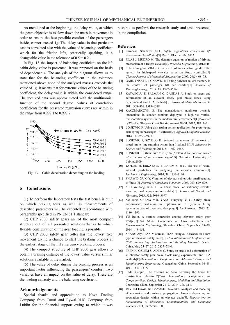
On the basis of the above mathematical dependencies,
the influence of the gears construction on the elevator braking parameters has been presented in Figs. 10–12.
Fig. 10. Effective braking distance depending
on the speed of the cabin
Fig. 11. Effective braking distance depending on the loading
Fig. 12. Cabin speed depending on the loading
CHINESE JOURNAL OF MECHANICAL ENGINEERING
·367·
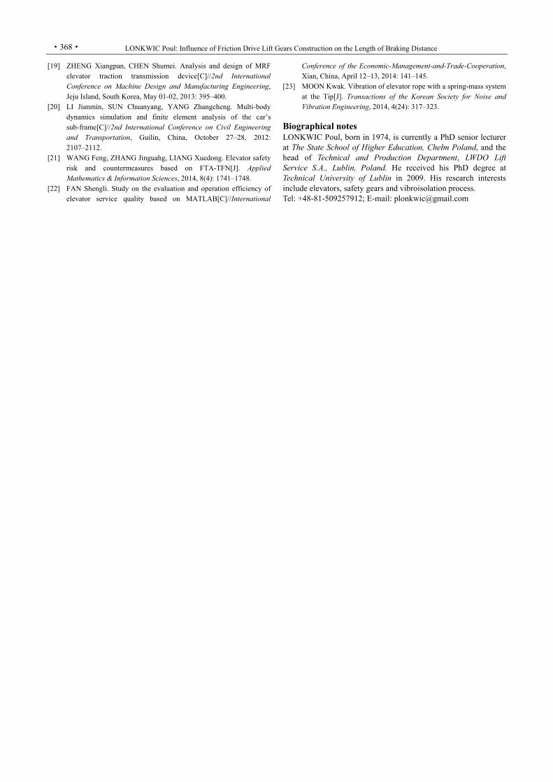
As mentioned at the beginning, the delay value, at which the gears objective is to slow down the mass in movement in order to ensure the best possible comfort of the passengers inside, cannot exceed 1g. The delay value in that particular case is correlated also with the value of balancing coefficient which for the friction lifts, practically speaking, is a changeable value in the tolerance of 0.5 0.2.
In Fig. 13 the impact of balancing coefficient on the lift cabin delay value is presented. It was prepared on the basis of dependence 4. The analysis of the diagram allows us to state that for the balancing coefficient in the tolerance mentioned above none of the analyzed masses exceeds the value of 1g. It means that for extreme values of the balancing coefficient, the delay value is within the considered range. The received data was approximated with the multinomial function of the second degree. Values of correlation coefficients for the presented regression curves are within in the range from 0.997 1 to 0.997 7.
Fig. 13. Cabin deceleration depending on the loading
5 Conclusions
(1) To perform the laboratory tests the test bench is built on which braking tests as well as measurements of described parameters will be executed in accordance with paragraphs specified in PN EN 81.1 standard.
(2) CHP 2000 safety gears are of the most compact structure out of all presented solutions thanks to which flexible configuration of the gear loading is possible.
(3) CHP 2000 safety gear roller has the lowest free movement giving a chance to start the braking process at the earliest stage of the lift emergency braking process.
(4) The compact structure of CHP 2000 gear allows to obtain a braking distance of the lowest value versus similar solutions available in the market.
(5) The value of delay during the braking process is an important factor influencing the passengers’ comfort. Two variables have an impact on the value of delay. These are the loading capacity and the balancing coefficient.
Acknowledgements Special thanks and appreciation to Nova Trading
Company from Toruń and Rywal-RHC Company from Lublin for the financial support owing to which it was
possible to perform the research study and tests presented in the compilation.
References [1] European Standards 81.1. Safety regulations concerning lift
structure and installation[S]. Part 1. Electric lifts, 2012. [2] FILAS J, MUDRO M. The dynamic equation of motion of driving
mechanism of a freight elevator[J]. Procedia Engineering, 2012: 48. [3] FENG Yonghui, ZHANG Jianwu. Hydraulics active guide roller
system for high-speed elevator based on fuzzy controller[J]. Chinese Journal of Mechanical Engineering, 2007, 20(5): 68–73.
[4] GARDYNSKI L, LONKWIC P. Testing polymer rollers memory in the context of passenger lift car comfort[J]. Journal of Vibroengineering, 2014, 16: 1392–8716.
[5] KAYAOGLU E, SALMAN O, CANDAS A. Study on stress and deformation of an elevator safety gear brake block using experimental and FEA methods[J]. Advanced Materials Research, 2011, 308–301: 1513–1518.
[6] KACZMARCZYK S. The nonstationary, nonlinear dynamic interactions in slender continua deployed in high-rise vertical transportation systems in the modern built environment[C]//Journal of Physics, Glasgow, Great Britain, August 28–31, 2012, 382: 1–6.
[7] LONKWIC P. Using disk spring solver application for prototyping disk spring in passenger lift catchers[J]. Applied Computer Science, 2014, 10: 2353–6977.
[8] LONKWIC P, SZYDLO K. Selected parameters of the work of speed limiter line straining system in a frictional lift[J]. Advances in Science and Technology, 2014, 21: 1662–0356.
[9] LONKWIC P. Wear and tear of the friction drive elevator wheel with the use of an acoustic signal[D]. Technical University of Lublin, 2009.
[10] TAPLAK H, ERKAYA S, YILDIRIM S, et al. The use of neural network predictors for analyzing the elevator vibrations[J]. Mechanical Engineering, 2014, 39: 1157–1170.
[11] ZHU W D, XU G Y. Vibration of elevator cables with small bending stiffness [J]. Journal of Sound and Vibration, 2003, 263: 679–699.
[12] ZHU Weidong, REN H. A linear model of stationery elevator travelling and compensation cables[J]. Journal of Sound and Vibration, 2013, 332: 3086–3097.
[13] XU Bing, CHENG Min, YANG Huayong, et al. Safety brake performance evaluation and optimization of hydraulic lifting systems in case of overspeed dropping[J]. Mechatronics, 2013, 23: 1180–1190.
[14] YU Bolin. A surface composite coating elevator safety gear wedge[C]//2nd Global Conference on Civil, Structural and Environmental Engineering, Shenzhen China, September 28–29, 2014: 148–151.
[15] ZHANG Ziyi, TAN Miaomiao, TIAN Hongyu. Research on a new type of elevator safety catch[C]//2nd International Conference on Civil Engineering, Architecture and Building Materials, Yantai China, May 25–27, 2012: 2837–2840.
[16] EREN K, OZLEM S, ADEM C. Study on stress and deformation of an elevator safety gear brake block using experimental and FEA methods[C]//International Conference on Advanced Design and Manufacturing Engineering, Guangzhou, China, September 16–18, 2011: 1513–1518.
[17] HAO Xiaojun. The research of Auto detecting the brake for construction elevator[C]//3rd International Conference on Computer-Aided Design, Manufacturing, Modeling and Simulation, Chongqing China, September 21–23, 2014: 308–311.
[18] MIYUKI Hirose, KOBAYASHI Takehiko. Analyses and modeling of ultra-wideband on-body propagation channels depending on
population density within an elevator cabin[J]. Transactions on Fundamental of Electronics Communications and Computer Sciences 2014, E97A: 94–100.
Y LONKWIC Poul: Influence of Friction Drive Lift Gears Construction on the Length of Braking Distance
·368·
[19] ZHENG Xiangpan, CHEN Shumei. Analysis and design of MRF elevator traction transmission device[C]//2nd International Conference on Machine Design and Manufacturing Engineering, Jeju Island, South Korea, May 01-02, 2013: 395–400.
[20] LI Jianmin, SUN Chuanyang, YANG Zhangcheng. Multi-body dynamics simulation and finite element analysis of the car’s sub-frame[C]//2nd International Conference on Civil Engineering and Transportation, Guilin, China, October 27–28, 2012: 2107–2112.
[21] WANG Feng, ZHANG Jinguahg, LIANG Xuedong. Elevator safety risk and countermeasures based on FTA-TFN[J]. Applied Mathematics & Information Sciences, 2014, 8(4): 1741–1748.
[22] FAN Shengli. Study on the evaluation and operation efficiency of elevator service quality based on MATLAB[C]//International
Conference of the Economic-Management-and-Trade-Cooperation, Xian, China, April 12–13, 2014: 141–145.
[23] MOON Kwak. Vibration of elevator rope with a spring-mass system at the Tip[J]. Transactions of the Korean Society for Noise and Vibration Engineering, 2014, 4(24): 317–323.
Biographical notes LONKWIC Poul, born in 1974, is currently a PhD senior lecturer at The State School of Higher Education, Chełm Poland, and the head of Technical and Production Department, LWDO Lift Service S.A., Lublin, Poland. He received his PhD degree at Technical University of Lublin in 2009. His research interests include elevators, safety gears and vibroisolation process. Tel: +48-81-509257912; E-mail: [email protected]