Embed Size (px)
Citation preview

IBERTRIB 2017 – IX Iberian Conference on Tribology, University of Minho, Guimarães, Portugal
- 1 -
Influence of swirl intensity on erosion-corrosion behaviour of pipeline steel beneath non submerged impinging jets
C. Sedano-de la Rosa a*, J. G. Godínez-Salcedo b, M. Vite-Torres a, E. A. Gallardo-Hernández a, D. E. Ramírez-Arreola c, Z. Martínez-Arriero a
a Instituto Politécnico Nacional, SEPI-ESIME-UZ, Grupo de Tribología, Col. Lindavista, C.P. 07320,
Cd. de México, México; b Instituto Politécnico Nacional, ESIQIE, Col. Lindavista, C.P. 07738, Cd. de
México, México; c Departamento de Ingenierías, Universidad de Guadalajara, Av. Independencia
Nacional # 151, Autlán de Navarro, Jalisco C.P. 48900, México
Synopsis
In the present study erosion-corrosion tests were conducted on API X-52 steel pipe coupons as target material. Tests were carried out at two regimes, non-swirling and swirling conditions as follows: S = 0, 0.1, 0.2 and 0.3, at flow velocity of 5 m/s. The slurry consisted of 1 l of distilled water containing 2 g/l NaCl and purged with CO2, abrasive particles of 20 µm Al2O3 were suspended into test solution with a content of 11 g/l. The impinging angle employed were 30°, 45°, 60° and 90°. Finally, electrochemical measurements were performed using the polarization resistance technique (Rp).
Introduction
Swirl flows are a common occurrence in engineering equipment; they are widely adapted in applications of engineering areas such as mechanical mixing, separation, combustion chambers, turbo machinery, and pollution control devices [1]. In 1899, the first application of swirl flows in pipeline field was reported, and deals with to divert the flowing liquid and sweep the deposited sediment up into the higher flowing body through the pipe [2]. In recent years, Wood et al. [3], studied the swirl flow inductions to reduce the erosion damage from slurries in pipeline bends. However, the erosion-corrosion wear behaviour of pipeline materials subjected to swirl flows has not been studied extensively.
Figure 1 - Erosion-corrosion tester device diagram.
Results and Discussion
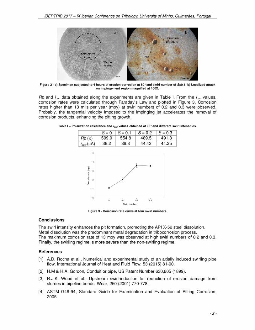
Figure 2(a) displays the wear scar obtained at swirl number of S = 0.1 and 60° after 4 hours
of erosion-corrosion testing, displaying a localized attack onto the impinging region.
Meanwhile, on the wall jet region the dissolved trace metal was observed with a centrifugal
trajectory from the stagnation point. Figure 2(b) illustrates a hole-shaped surface related to
pitting corrosion. The evaluation of pitting corrosion obtained along the experiments was
performed according to G46-94 ASTM Standard [4], including: size, shape, density,
uniformity of distribution and depth.
IBERTRIB 2017 – IX Iberian Conference on Tribology, University of Minho, Guimarães, Portugal
- 2 -
Figure 2 - a) Specimen subjected to 4 hours of erosion-corrosion at 60° and swirl number of S=0.1; b) Localized attack on impingement region magnified at 100X.
Rp and icorr data obtained along the experiments are given in Table I. From the icorr values, corrosion rates were calculated through Faraday’s Law and plotted in Figure 3. Corrosion rates higher than 13 mils per year (mpy) at swirl numbers of 0.2 and 0.3 were observed. Probably, the tangential velocity imposed to the impinging jet accelerates the removal of corrosion products, enhancing the pitting growth.
Table I – Polarization resistance and icorr values obtained at 90° and different swirl intensities.
S = 0 S = 0.1 S = 0.2 S = 0.3
Rp (W) 599.9 554.8 489.5 491.3
icorr (μA) 36.2 39.3 44.43 44.25
Swirl number
0 0.1 0.2 0.3
Corrosio
n rate
(m
py)
10
11
12
13
14
15
Figure 3 - Corrosion rate curve at four swirl numbers.
Conclusions
The swirl intensity enhances the pit formation, promoting the API X-52 steel dissolution. Metal dissolution was the predominant metal degradation in tribocorrosion process. The maximum corrosion rate of 13 mpy was observed at high swirl numbers of 0.2 and 0.3. Finally, the swirling regime is more severe than the non-swirling regime.
References
[1] A.D. Rocha et al., Numerical and experimental study of an axially induced swirling pipe flow, International Journal of Heat and Fluid Flow, 53 (2015) 81-90.
[2] H.M & H.A. Gordon, Conduit or pipe, US Patent Number 630,605 (1899).
[3] R.J.K. Wood et al., Upstream swirl-induction for reduction of erosion damage from slurries in pipeline bends, Wear, 250 (2001) 770-778.
[4] ASTM G46-94, Standard Guide for Examination and Evaluation of Pitting Corrosion, 2005.
a) b)


![J. - infoscience.epfl.ch Analysis... · swirl intensity on the flow behavior in the draft tube is well-investigated relating to the pressure pulsations [2]. Little is reported, however,](https://img.pdfslide.net/doc/110x75/5ca4e23c88c99313358c16cb/j-analysis-swirl-intensity-on-the-flow-behavior-in-the-draft-tube-is-well-investigated.jpg)