Embed Size (px)
Citation preview
ABSTRACT The leakage flow across the shroud of turbine blades causes sub-stantial aerodynamic losses as it mixes with the freestream flow within the main annulus. The present paper shows the measurement results of two different rotor sealing designs in turbo machines in combination with tangential end wall contouring. Tests are con-ducted at 2-stage turbine integrated in an air cycle, located at the Institute of Power Plant Technology, Steam and Gas Turbines, RWTH Aachen University. Two operating points characterized by the stage loading coefficient at design and overload conditions are analyzed. Constant section shrouded airfoils are sealed by means of labyrinth seals as well as combined labyrinth- and brush seals. The investigations show the impact of the brush seal to the efficiency and respectively to the secondary flow. The pressure level within each cavity chamber is measured, which allows the analysis of the seal’s pressure drop and the corresponding mass flow that passes through the flow path above the shroud in detail. The flow profiles in several measurement planes are recorded along the radial height of the annulus thus the thermodynamic parameters as well as the flow direction are determined precisely. Therefore the impact of the different sealing types to the main flow can be visualized. Addition-ally the pressure distribution of one stator vane at the second stage is measured on two radial positions to detect changes of blade load-ing due to the brush seal application. The investigation turns out that the leakage flow is blocked for the configuration with brush seal thus mixing effects are inhibited however rotor – stator inter-action is considered. It is also shown that the reduced leakage flow supports the impact of the end wall contouring which leads to sig-nificant benefits in off design operation.
NOMENCLATURE cB Clearance between backing plate and rotor k Straddle factor L Characteristic length Ma Mach number p Pressure r Shroud radius T Temperature x Relative pitch x/l Relative chord length z Number of sealing tips
Symbols α Yaw angle alpha δ Clearance εB Specific outflow number κ Isentropic coefficient µ Passage coefficient υ Specific volume
φ Flow coefficient ψ Stage loading coefficient (both stages)
Subscripts 10 Plane upstream of the first stage 12 Plane between the two stages 22 Plane downstream of the second stage is Isentropic pol Polytropic r Rotor t-t Total to total thermodynamic state
Abbreviations 3HP 3-hole probe 5HP 5-hole probe BS Brush seal CFD Computational fluid dynamics DP Design Point FLS Full labyrinth seal GRLS Groove ridge labyrinth seal LS Labyrinth seal MP Measurement plane OP Operating point PAD Probe adjusting device PDV Pressure distribution vane PS Pressure side RCL Relative chord length RPM Revolutions per minute SS Suction side STLS Straight through labyrinth seal TP Temperature probe TEWC Tangential end wall contouring INTRODUCTION Environmental concerns, scarcity of fossil resources and related economic reasons are motivation for efficiency maximization of thermal power plants. Efficiency optimization of steam turbines in-tegrated in these systems is an effective approach. Sealing of the rotating parts is one important aspect to increase the efficiency due to reduced leakage flow. Leakage losses constitute inner losses of turbo machines as well as profile or secondary losses. In general, their amount is propor-tional to the gap above the shroud, however, they are caused by the pressure difference of the sealed section. Büscher [1] showed that the pressure gradient is substantial for the leakage across a stage. Thus stators vanes of impulse blading show higher leakages than rotor blades. The leakage flow impacts the mainstream significantly in different ways. On the one hand less fluid participates in energy conversion, on the other hand it modifies the incident flow to the
Influence of tip seal configurations on flow and efficiency for shrouded turbine blades
Tobias W. Zimmermann1, Oliver Curkovic1, Manfred Wirsum1
1 Institute of Power Plant Technology, Steam and Gas Turbines, RWTH Aachen University, 52072 Aachen, Germany
Copyright © 2016 Gas Turbine Society of Japan
International Journal of Gas Turbine, Propulsion and Power Systems July 2016, Volume 8, Number 2
Presented at International Gas Turbine Congress 2015 Tokyo November 15-20, Tokyo, Japan Manuscript Received on Janualy 6, 2016 Review Completed on June 15, 2016 9
next stage. These effects cause losses due to flow interaction and mixing losses and finally lead to a reduction of efficiency. Labyrinth Seals Labyrinth seals (LS) are commonly used if gaps between mov-ing and fixed parts have to be sealed contactless. They are well suited to meet applications with high rotational speed and tempera-ture due to their robust design. In addition a constant sealing per-formance can be guaranteed for a long period. The reduction of the leakage flow is realized by increasing the flow resistance. Therefore, LS consists of several seal tips which are located at the casing or hub side only (straight through labyrinth seal (STLS), or on both sides (full labyrinth seal (FLS) or groove ridge labyrinth seal (GRLS)). The mountability of STLS is simple, however, the sealing performance is about 40% lower compared to FLS with similar ax-ial length. 50 – 70% of the sealing effectivity of the FLS can be achieved with GRLS [2]. A minimal gap of 1-2‰ hub diameter has to be realized to avoid contact during start up or while passing the critical bending speed of the rotor. Concurrently, the gap has to be minimized to optimize the sealing performance. Matthias [3] discusses the vortex phenom-ena within the cavities extensively. The more tips are connected in series, the better the sealing, however, the space is limited [4]. Brush Seals Brush seals were initially developed for the aviation industry, improved and implemented in stationary steam turbines in 2000 for the first time [5]. During the last years several labyrinth seals in power plants have been replaced by brush seals as part of retrofit measures. Combinations of LS and BS are the most effective design and installed in new plants. [6]. Sealing of the rotor against the en-vironment is the main application area of BS, however, shrouded blades are sealed with this technology, too. In general BS can be characterized by two different designs. One design contains a backing plate, the brush and a front plate that are tightened together with a surrounding weld seam. The second de-sign consists of a brush package that is clamped backing and front plate. 25% reduced installation height, a reduced weight and sim-plified mounting distinguish this design. In addition, nonmetallic materials can be used as bristles [7]. BS can be mounted with a gap or overlapping to the rotor, however, in this case wear has to be taken into account. The flow within the BS is quite complex and several design pa-rameters such as axial inclination, laying angle, bristle diameter or brush thickness have to be taken into account to implement an ap-propriate seal. Further information is provided by Schwarz et al. [6][8] and is not further elaborated in this paper due to the focus of the engine’s efficiency. Tangential End Wall Contouring The reduction of secondary losses is one of the main approaches to enhance the efficiency of turbomachines. A first design of a non-axisymmetric contour was published by Bischoff [9] in 1983. The motivation is to influence the pressure gradient between suction side (SS) and pressure side (PS), selectively. Today’s designs show various shapes due to numerical predic-tions. Previous investigations by e.g. Atkins et al.[10], Brennan et al.[11], Harvey et al.[12], or Hartland et al.[13] have shown that tangential end wall contouring has the potential to increase the ef-ficiency. Regarding the benefit for off design, the investigations showed different results. Schwab [14] summarized the current sta-tus of research in 2014. His investigations on the later described test rig supported the increase of efficiency for part load, however, he
did not see a benefit for higher blade loading. The present paper expands the investigations by stopping the in-fluence of leakage flow, however, rotor – stator interaction is con-sidered. This procedure ensures an undisturbed incident flow on the TEWC which supports its impact on the flow thus the effects can be investigated more precisely.
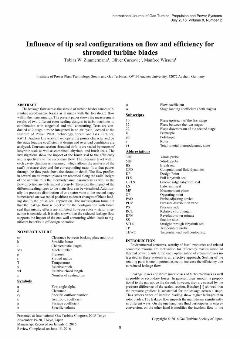
EXPERIMENTAL SETUP This paper shows how changes of the sealing design for shrouded rotors impacts the flow and efficiency. Therefore a 2 stage air driven turbine is equipped with constant section shrouded high pressure airfoils and tangential end wall contouring (TEWC) on hub and casing side. Fig.1 illustrates the test rig of the Institute for Power Plant Technology, Steam and Gas Turbines, RWTH Aachen University. Air supply is realized by two radial compressors in a closed loop to avoid environmental impact to the measurement. The inlet tem-perature is established at 90°C with a tolerance of ±0,5K by means of a bypass that adjusts the amount of flow through a cooling unit. A honeycomb is installed in front of the first stator row to ensure uniform and reproducible flow conditions. Rotational speed is ad-justed by means of a water brake that is mounted on a swing frame with hydrostatic bearing. That allows sensitive measurement of the torque with a load cell connected to a lever that transmits the force. A maximum mass flow of 13.9kg/s can be supplied at 3.2 ∙ 105 𝑃𝑎 and a deviation of 3‰ at the inlet of the turbine. A non-symmetric flow at the outlet of the turbine is caused by the water brake. Swirl barriers are installed downstream the last rotor to avoid any influ-ence on the measurement behind the second stage and an outlet pressure of 2.31 ∙ 105 𝑃𝑎 is set. A calibrated orifice is used to de-termine the mass flow. Tab. 1 summarizes the specifications of the turbine at its design point (DP) operating point 3.The thermody-namic boundary conditions are kept constant for all other operating points (OP). Only speed, respectively the stage loading coefficient is varied.
Fig. 1 2 stage axial turbine
Table 1 Specifications of the turbine at design point
Inlet pressure [Pa] 3.2 ∙ 105 Outlet pressue [Pa] 2.31 ∙ 105 Inlet temperature [°C] 90 Speed [RPM] 4775 Mass flow [kg/s] 12.37 Flow coefficient φ [-] 0.5 Stage loading coefficient ψ [-] 2.58
JGPP Vol.8, No. 2
10
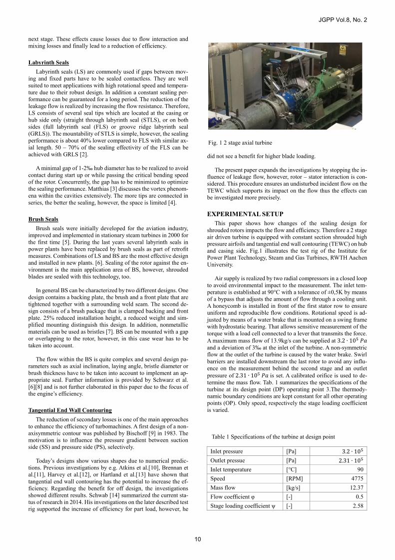
The turbine contains several measuring planes (MP) that are shown in Fig.2. Wall pressures are measured on several circumfer-ential positions in each MP on hub as well as on the casing side. In addition probe adjusting devices (PADs) are installed in MP10, MP12 and MP22 to record the flow profile over the full channel height. 3-hole probes (3HP), 5-hole probes (5HP) and temperature probes (TP) are therefore positioned precisely within the flow chan-nel. CFD simulations are used as basis to turn the probe head face to the flow at each radial position. Clocking of both stator rows over an area of 1.2 pitches allows to detect the full flow profile of one airfoil passage. The resulting probe grid contains 392 measuring points. As one can see in Fig.1, the TP are shifted by 90° compared to the pressure probes. This instrumentation design allows to meas-ure pressure and temperature at the same time and channel height. Changing the probe design from 3HP to 5HP requires an additional test day thus each OP is investigated redundantly. By altering the measuring sequence (3HP: OP1 → OP4, 5HP: OP4 → OP1) as well as by inversion of the clocking direction it can be outlined that the measurements are influenced by systematic errors. The second stator row contains a prepared vane (PDV) to determine the pressure distribution along suction (SS) and pressure side (PS) on two radial heights (50% = centred and 90% = casing side) with 13 measurement positions each. Four rakes containing five Kiel headed probes which are equally distributed over the channel height are located in the outlet plane to detect total pressure. The influence of the rotor sealing design to the TEWC is focus of the present paper. The first tests were carried out with a GRLS consisting of three sealing tips over the shroud. The axial clearance at the inlet and outlet of the cavity is set to 20% chord length. The radial gap is set to 2.2% outer shroud diameter however changes due to different speed respectively centrifugal forces have to be taken into account. The second set of investigations is conducted by replacing the centred labyrinth tip with a brush seal. The bristles touch the rotor from the very beginning to ensure a closed clearance
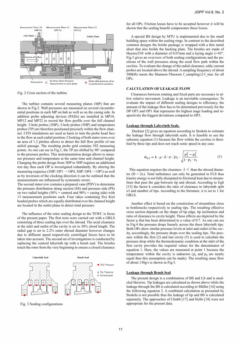
for all OPs. Friction losses have to be accepted however it will be shown that the sealing benefit compensates these losses. A special BS design by MTU is implemented due to the small building space within the sealing rings. In contrast to the described common designs the bristle package is wrapped with a thin metal sheet that also builds the backing plate. The bristles are made of Haynes25® with a diameter of 0.07mm and a laying angle λ=45°. Fig.3 gives an overview of both sealing configurations and the po-sitions of the wall pressures along the axial flow path within the cavities. To evaluate the change of the radial clearance, eddy current probes are located above the shroud. A sampling frequency of about 500kHz meets the Shannon-Theorem f_sampling≥2∙f_max for all OPs. CALCULATION OF LEAKAGE FLOW Clearances between rotating and fixed parts are necessary to al-low relative movement. Leakage is an inevitable consequence. To evaluate the impact of different sealing designs to efficiency, the amount of the leakage flow has to be determined previously for the DP OP3 and OP1 that represents the highest stage loading and re-spectively the biggest deviations compared to OP3.
Leakage through Labyrinth Seals. Deckner [2] gives an equation according to Stodola to estimate the leakage flow through labyrinth seals. It is feasible to use the subsonic equation (1) because the flow within the cavities is throt-tled by three tips and does not reach sonic speed in any case.
�̇�𝐿𝑆 = 𝑘 ∙ 𝜇 ∙ 𝛿 ∙ 𝜋 ∙ 2𝑟𝑟 ∙ √𝑝2
2 − 𝑝52
𝑧 ∙ 𝑝1 ∙ 𝜐1 (1)
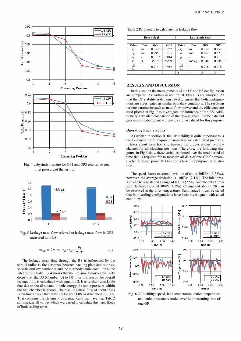
This equation requires the clearance δ≪ than the shroud diame-ter (D = 2rr). Total turbulence can only be generated in FLS thus kinetic energy is not fully dissipated to frictional heat due to stream-lines that pass the gap between tip and shroud. According to Egli [15] the factor k considers the ratio of clearance to labyrinth split s/t and number of tips. According to the literature, it is set to 1 for GRLS. Another effect is based on the constriction of streamlines close to bottlenecks respectively to sealing tips. The resulting effective cross section depends on the shape of tip edge, tip inclination and ratio of clearance to cavity height. These effects are depicted by the factor µ that has been determined to a value of 0.7. As one can see in Fig.4 the pressure drops linearly across the three labyrinth tips. Both OPs show similar pressure levels at inlet and outlet of the cav-ity, accordingly, the pressure drops over the sealing tips. The pres-sure within the first (2) and last cavity (5) is used to calculate the pressure drop while the thermodynamic condition at the inlet of the first cavity provides the required values for the denominator of equation 1. Here, the values are measured at point 1 because the temperature within the cavity is unknown (𝑝1 and 𝑝2 are nearly equal thus this assumption can be made). The resulting mass flow of about 130g/s is shown in Fig.5. Leakage through Brush Seal The present design is a combination of BS and LS and is mod-eled likewise. Tip leakages are calculated as shown above while the leakage through the BS is calculated according to Müller [16] using the following equation 2. A combined calculation as presented by Stodola is not possible thus the leakage of tip and BS is calculated separately. The approaches of Chubb [17] and Holle [18] were not appropriate for the present data.
Fig. 2 Cross section of the turbine
Fig. 3 Sealing configurations
JGPP Vol.8, No. 2
11
�̇�𝐵𝑆 = 2𝜋 ∙ 𝑟𝑟 ∙ 𝑐𝐵 ∙ 휀𝐵∙ ∙𝑝1
𝑅 ∙ 𝑇1 (2)
The leakage mass flow through the BS is influenced by the shroud radius rr, the clearance between backing plate and rotor cB, specific outflow number εB and the thermodynamic condition at the inlet of the cavity. Fig.4 shows that the pressure almost exclusively drops over the BS (chamber (3) to (4)). For this reason the overall leakage flow is calculated with equation 2. It is further remarkable that due to the dissipated kinetic energy the static pressure within the first chamber increases. The resulting mass flow of about 15g/s is ten times lower than with LS for both OPs as illustrated in Fig.5. That confirms the statement of a practically tight sealing. Tab. 2 summarizes all values which were used to calculate the mass flows of both sealing types.
RESULTS AND DISCUSSION In this section the measurements of the LS and BS configuration are compared. As written in section III, two OPs are analysed. At first the OP stability is demonstrated to ensure that both configura-tions are investigated at similar boundary conditions. The resulting turbine parameters such as mass flow, power and the efficiency are used plotted in Fig. 7 to investigate the influence of the BS. Addi-tionally a detailed comparison of the flow is given. Probe data and pressure distribution measurements are visualized for this purpose. Operating Point Stability As written in section II, the OP stability is quite important thus the tolerances for all required parameters are established precisely. It takes about three hours to traverse the probes within the flow channel for all clocking positions. Therefore, the following dia-grams in Fig.6 show these variables plotted over the total period of time that is required for to measure all data of one OP. Compara-tively the design point OP3 has been chosen for purpose of illustra-tion. The speed shows maximal deviation of about 30RPM (6.28‰), however, the average deviation is 10RPM (2.1‰). The inlet pres-sure can be adjusted in a range of 800Pa (2.5‰) and the outlet pres-sure fluctuates around 300Pa (1.3‰). Changes of about 0.2K can be observed at the inlet temperature. Summarized it can be stated that both sealing configurations have been investigated with equal conditions.
Fig. 4 Labyrinth pressure for OP1 and OP3 referred to total
inlet pressure.of the test rig
Fig. 5 Leakage mass flow referred to leakage mass flow in OP3 measured with LS.
Table 2 Parameters to calculate the leakage flow
Brush Seal Labyrinth Seal
Value Unit OP1 OP3 Value Unit OP1 OP3 𝑟𝑟 m 0.2522 0.252 𝑟𝑟 m 0.252 0.252 𝑐𝐵 mm 0.795 0.795 𝛿 mm 0.562 0.523 휀𝐵∙ - 0.0133 0.014 𝜇 - 0.7 0.7 𝑇1 K 356.9 355.9 𝜐1 m³/kg 0.348 0.345 𝑝5
𝑝2
- 0.914 0.912 𝑝5
𝑝2
- 0.918 0.918
z - 3 3
Fig. 6 OP stability: speed, inlet temperature, outlet temperature
and outlet pressure recorded over full measuring time of one OP
JGPP Vol.8, No. 2
12
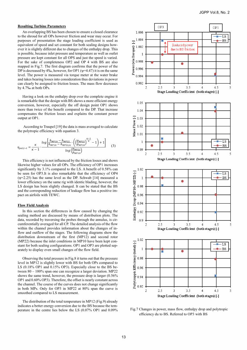
Resulting Turbine Parameters An overlapping BS has been chosen to ensure a closed clearance to the shroud for all OPs however friction and wear may occur. For purposes of presentation the stage loading coefficient is used as equivalent of speed and set constant for both sealing designs how-ever it is slightly different due to changes of the enthalpy drop. This is possible, because inlet pressure and temperature as well as outlet pressure are kept constant for all OPS and just the speed is varied. For the sake of completeness OP2 and OP 4 with BS are also mapped in Fig.7. The first diagram confirms that the power of the DP is decreased by 4‰, however, for OP1 (ψ=4.47) it is on the same level. The power is measured via torque meter at the water brake and takes bearing losses into consideration thus deviations in power can clearly be assigned to friction losses. The mass flow decreases by 4.7‰ at both OPs. Having a look on the enthalpy drop over the complete engine it is remarkable that the design with BS shows a more efficient energy conversion, however, especially the off design point OP1 shows more than twice of the benefit compared to the DP. That increase compensates the friction losses and explains the constant power output at OP1. According to Traupel [19] the data is mass averaged to calculate the polytropic efficiency with equation 3.
𝜂𝑝𝑜𝑙,𝑡−𝑡 =𝜅
𝜅 − 1∙
𝑙𝑜𝑔 [ℎ𝑀𝑃10 − ℎ𝑀𝑃22
ℎ𝑀𝑃10 − ℎ𝑀𝑃22,𝑖𝑠∙ ((
𝑝𝑀𝑃22
𝑝𝑀𝑃10)
𝜅−1𝜅
− 1) + 1]
𝑙𝑜𝑔 (𝑝𝑀𝑃22
𝑝𝑀𝑃10)
(3)
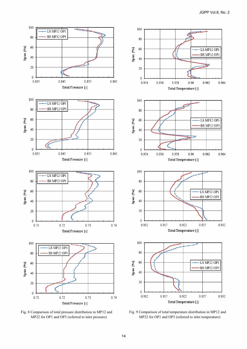
This efficiency is not influenced by the friction losses and shows likewise higher values for all OPs. The efficiency of OP1 increases significantly by 3.1% compared to the LS. A benefit of 0.58% can be seen for OP3.It is also remarkable that the efficiency of OP4 (ψ=2.25) has the same level as the DP. Schwab [14] measured a lower efficiency on the same rig with identic blading, however, the LS design has been slightly changed. It can be stated that the BS and the corresponding reduction of leakage flow has a positive im-pact on airfoils with TEWC. Flow Field Analysis In this section the differences in flow caused by changing the sealing method are discussed by means of distribution plots. The data, recorded by traversing the probes through the annulus, is cir-cumferentially averaged for all CP. The detailed analysis of the flow within the channel provides information about the changes of in-flow and outflow of the stages. The following diagrams show the distribution downstream of the first (MP12) and second rotor (MP22) because the inlet conditions in MP10 have been kept con-stant for both sealing configurations. OP1 and OP3 are plotted sep-arately to display even small changes of the flow field. Observing the total pressure in Fig.8 it turns out that the pressure level in MP12 is slightly lower with BS for both OPs compared to LS (0.18% OP1 and 0.15% OP3). Especially close to the BS be-tween 80 – 100% span one can recognize a larger deviation. MP22 shows the same trend, however, the pressure drop is larger (0.56% OP1 and 0.60% OP3). Therefore, the offset is nearly constant across the channel. The course of the curves does not change significantly in both MPs. Only for OP3 in MP22 at 80% span the curve is smoothed compared to LS measurement. The distribution of the total temperature in MP12 (Fig.9) already indicates a better energy conversion due to the BS because the tem-perature in the centre lies below the LS (0.07% OP1 and 0.09%
Fig.7 Changes in power, mass flow, enthalpy drop and polytropic efficiency du to BS. Referred to OP3 with BS
JGPP Vol.8, No. 2
13
friction cannot be assigned definitely. The curve shapes looks simi
Fig. 8 Comparison of total pressure distribution in MP12 and
MP22 for OP1 and OP3 (referred to inlet pressure)
Fig. 9 Comparison of total temperature distribution in MP12 and MP22 for OP1 and OP3 (referred to inlet temperature)
JGPP Vol.8, No. 2
14
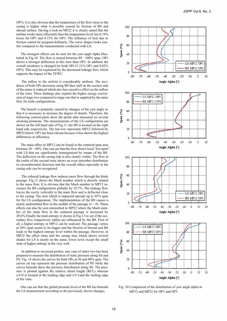
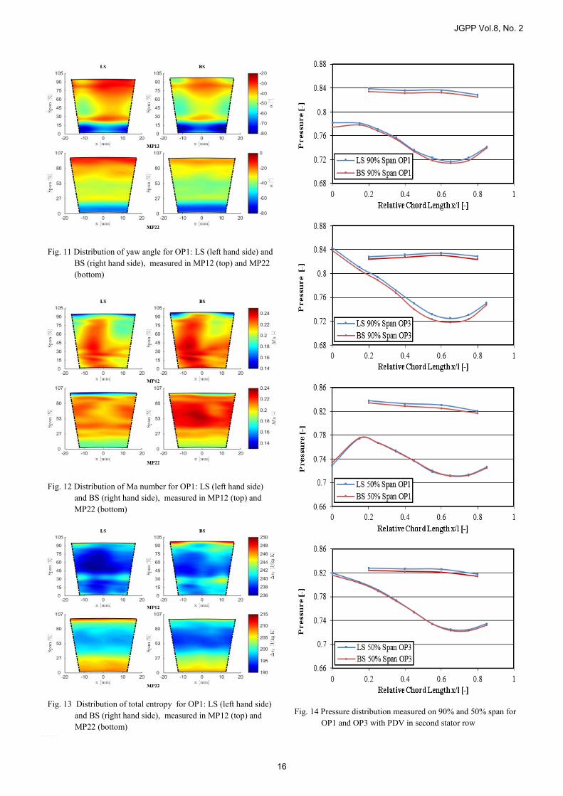
OP3). It is also obvious that the temperature of the flow close to the casing is higher what is possibly caused by friction of BS and shroud surface. Having a look on MP22 it is clearly stated that the turbine works more efficiently thus the temperature level lies 0.19% lower for OP1 and 0.15% for OP3. The influence of heat due to friction cannot be assigned definitely. The curve shapes looks sim-ilar compared to the measurements conducted with LS. The strongest effects can be seen for the yaw angle alpha illus-trated in Fig.10. The flow is turned between 80 - 100% span. OP1 shows a stronger deflection in this area than OP3. In addition the overall incidence is changed for both OPs (5.31% OP1 and 4.82% OP3). This may be explained by the decreased leakage flow which supports the impact of the TEWC. The inflow to the airfoils is considerably uniform. The inci-dence of both OPs decreases using BS thus stall on the suction side of the stator is reduced which also has a positive effect on the inflow of the rotor. These findings also explain the higher energy conver-sion of stage two compared to stage one that is supplied by the same flow for both configurations. The benefit is primarily caused by changes of the yaw angle so that it is necessary to increase the degree of details. Therefore, the following contour-plots show the probe data measured on several clocking positions. The measurements of the LS configuration are shown on the left hand side of Fig.11, the BS is located on the right hand side respectively. The top row represents MP12 followed by MP22 below. OP1 has been chosen because it has shown the highest differences in efficiency. The main effect in MP12 can be found in the centered span area between 30 – 60%. One can see that the flow shows local “hot spots” with LS that are significantly homogenized by means of the BS. The deflection on the casing side is also clearly visible. The flow at the outlet of the second rotor shows an even smoother distribution in circumferential direction and the overall offset especially at the casing side can be recognized. The reduced leakage flow induces more flow through the blade passage. Fig.12 shows the Mach number which is directly related to the mass flow. It is obvious that the Mach number in MP12 in-creases for BS configuration globally by 10.7%. The leakage flow leaves the cavity vertically to the main flow and is deflected close to the casing. The area which is impacted spreads up to 95% span for the LS configuration. The implementation of the BS causes a nearly undisturbed flow in the middle of the passage (x = 0). These effects can also be seen intensified in MP22 where the Mach num-ber of the main flow in the centered passage is increased by 20.6%.Finally the total entropy is shown in Fig.13 to see if the sec-ondary flow respectively eddies are influenced by the BS. First of all, a higher entropy in MP12 can be realized. The passage vortex at 20% span seems to be bigger and the friction of shroud and BS leads to the highest entropy level within the passage. However, in MP22 the effect turns and the casing area which shows several shades for LS is nearly on the same, lower level except the small strip of higher entropy at the very wall. In addition to traversed probes, one vane of stator two has been prepared to measure the distribution of static pressure along SS and PS. Fig. 14 shows the curves for both OPs at 50 and 90% span. The curves on top represent the pressure distribution of PS while the curves beneath show the pressure distribution along SS. The pres-sure is plotted against the relative chord length (RCL) whereas x/l=0 is located at the leading edge and x/l=1and the trailing edge of the vane. One can see that the global pressure level of the BS lies beneath the LS measurement according to the previously shown changes.
Fig. 10 Comparison of the distribution of yaw angle alpha in MP12 and MP22 for OP1 and OP3
JGPP Vol.8, No. 2
15
OP3.
Fig. 11 Distribution of yaw angle for OP1: LS (left hand side) and BS (right hand side), measured in MP12 (top) and MP22 (bottom)
Fig. 12 Distribution of Ma number for OP1: LS (left hand side) and BS (right hand side), measured in MP12 (top) and MP22 (bottom)
Fig. 13 Distribution of total entropy for OP1: LS (left hand side)
and BS (right hand side), measured in MP12 (top) and MP22 (bottom)
Fig. 14 Pressure distribution measured on 90% and 50% span for OP1 and OP3 with PDV in second stator row
JGPP Vol.8, No. 2
16
While the curves on the PS look similar for each span and OP, changes can be noticed on the SS. On 90% span the pressure level is constant from leading edge to 20% RCL for OP1. The BS config-uration shows an increase in this section before the flow is acceler-ated similar to LS. No changes can be found at the trailing edge of OP3. Behind 30% RCL the flow is stronger accelerated and the re-covery of static pressure seems to work better as one may see on the last measuring position that has the same level than the LS con-figuration. As expected the changes at 50% span are quite small compared with the flow area that is located close to the casing and respectively the BS and TEWC.
CONCLUSION The present paper shows the results of investigations carried out on a 2 stage air driven test turbine. The focus lies on the influence of the shroud sealing to end wall contoured airfoils. The investiga-tions of Schwab [14] are extended with the goal to suppress the mixing effects of leakage flow and main flow. The impact of rotor – stator interaction is considered. Therefore, two configurations with constant section shrouded airfoils have been investigated for two operating points. OP3 repre-sents the design point while OP1 stands for a higher stage loading coefficient. The first sealing configuration is a groove ridge laby-rinth seal consisting of three sealing tips. To investigate the influ-ence of the brush seal, the centered seal tip has been replaced by a brush seal for the second configuration. By means of the brush seal the leakage flow could be reduced up to 89%. A detailed flow analysis has shown that especially the second stage performs better due to the proper inflow of the first stage and the reduced mixing effects of leakage flow and main flow. In both stages the flow is more uniform than before. Measurements with a pressure distribution vane have shown that the incidence has become better, especially at off design. A global analysis of the turbine parameters turned out that the corresponding mass flow is lower for the brush seal by keeping the inlet conditions constant. Also the power measured via torque de-creases which is related to the friction losses of brush seal and shroud. Nevertheless, the polytropic efficiency of both operating points is increased. OP1 shows a 3.1% higher efficiency while the efficiency of OP3 is increased by 0.58%. A main reason for this ef-fect is a better incidence close to the casing and a homogenized flow field within the flow channel. The findings of this paper support the statement that decreasing the leakage flow enhances the impact of TEWC and respectively the turbine efficiency especially in off desing.
ACKNOWLEDGMENT The numerical and experimental investigations were conducted as part of the joint research program COORETEC-Turbo in AG Turbo. The work has been supported by the Bundesministerium für Wirtschaft und Technologie (BMWi) (file number 03ET2013) on the basis of a resolution of the German Parliament. The authors gratefully acknowledge AG Turbo and Alstom Power for their sup-port and permission to publish this paper. The responsibility for the content of this publication lies with the authors.
REFERENCES Büscher, S., 2009, „Untersuchung von mehrstufigen Bürsten-
dichtungen für Dampfturbinen“, TU Braunschweig; ISBN 978-3-929682-47-2, 2010
Deckner, M., 2010, „Eigenschaften kombinierter Labyrinth-Bürstendichtungen für Turbomaschinen“, TU München
Matthias, A., 2007, „Das Durchflussverhalten von Labyrinth-dichtungen bei unterschiedlichen Betriebsbedingungen“, TU Wien
Haas, W., 1997, „Berührungsfreies Abdichten im Maschinen-bau unter besonderer Berücksichtigung der Fanglabyrinthe“, Habilitationsschrift, Stuttgart
Pastrana, R., Wolfe, C., Turnquist, A., Burnett, M., 2001, “Im-proved Steam Turbine Leakage Control with a Brush Seal De-sign”, GE Energy Services,
Schwarz, H., Friedrichs, J., Flegler, J., 2014, “Axial Inclina-tion of the Bristle Pack, a new Design Parameter of Brush Seals for Improved Operational Behavior in Steam Turbines”, Proceedings of ASME Turbo Expo, Paper GT2014-26330
Gail, A., Beichl, S., 2000, “MTU Brush Seal - Main Features of an Alternative Design”, 36th AIAA/ASME/SAE/ASEE Joint Propulsion Conference & Exhibit, AIAA Paper 2000-3375
Schwarz, H., Friedrichs, J., Flegler, J., 2012, “Design Parame-ters of Brush Seals and their Impact on Seal Performance”, Proceedings of ASME Turbo Expo 2012; Paper GT2012-68956
Bischoff, H., 1983, Patent document, DE3202855 C1 Atkins, M.J., 1987, ”Secondary Losses and End-wall Profiling in a Turbine Cascade”; IMechE-Paper C255/87
Brennan, G., Harvey, N.W., Rose; M.G., Fomison, N., Taylor , M.D., 2003, “Improving the Efficiency of the Trent 500-HP Turbine Using Nonaxisymmetric End Walls-Part I: Turbine Design”, ASME Journal of Turbomachinery, S. 497-504, Vol.125
Harvey, N.W., Brennan, G., Newman, D.G, Rose, M.G., 2002, “Improving Turbine Efficiency Using Non-Axissymmetric End Walls: Validation in the Multi-Row Environment and with Low Aspect Ratio Blading”, ASME-Paper 2002-GT-30337, Amsterdam, Netherlands
Hartland, J.C., Gregory-Smith, D.G., Harvey, N.W., Rose, M.G., 2000, “Nonaxisymmetric Turbine End Wall Design: Part II - Experimental Validation”, ASME Journal of Tur-bomachinery, S. 286-293, Vol. 122
Schwab, S., 2014, “Experimentelle Untersuchung von um-fangs-unsymmetrischen Dampfturbinenbeschaufelungen und von Temperaturausgleichspänomenen an einer 2-stufigen Ver-suchsturbine, Diss. RWTH Aachen
Egli, A., 1935, “The Leakage of steam through labyrinth seals”, Transactions of the ASME FSP-57-5, Fuels and Steam Power, P. 115 - 122
Müller, H. K, 1990, .“Abdichtung bewegter Maschinenteile“, Medienverlag Ursula Müller, Waiblingen
Chupp, R.E., Ghasripoor, F., Turnquist, N. A., Demiroglu, M., Aksit, M. F., 2002, “Advanced Seals for Industrial Turbine Applications: Dynamic Seal Development”; Journal of Pro-pulsion and Power, Vol. 18, No. 6, P. 1260 – 1266
Chupp, R. E., Holle, G. F., 1996, “Generalizing Circular Brush Seal Leakage Through a Randomly Distributed Bristle Bed”; Journal of Turbomachinery, Vol. 118, P. 153 - 161, 1996
Traupel, W., 1969, „Die Theorie der Strömung durch Radial-maschinen“, Karlsruhe, Verlag G. Braun
JGPP Vol.8, No. 2
17