Embed Size (px)
Citation preview
Ii
TGT
a
A
R
R
1
A
K
E
G
C
B
S
D
C
T
1
MiacfleeospM1
0d
j o u r n a l o f m a t e r i a l s p r o c e s s i n g t e c h n o l o g y 2 0 2 ( 2 0 0 8 ) 61–69
journa l homepage: www.e lsev ier .com/ locate / jmatprotec
nfluence of tool inclination on brittle fracturen glass cutting with ball end mills
akenori Ono, Takashi Matsumura ∗
raduate School of Mechanical Engineering, Department of Mechanical Engineering,okyo Denki University, 2-2 Kanda-Nishiki-cho, Chiyoda-ku, Tokyo 101-8457, Japan
r t i c l e i n f o
rticle history:
eceived 13 September 2006
eceived in revised form
7 June 2007
ccepted 16 August 2007
eywords:
nd mill
lass
a b s t r a c t
Glass milling is discussed with influences of tool inclination on brittle fracture. Cutting
tests are performed to observe surfaces in the up-cut and the down-cut processes with a
ball end mill inclined in the feed direction of the cutter. Brittle fracture occurs in the down-
cut process at high feed rates. Then the machined surfaces in cutting with the ball end mills
tilted in the vertical plane with respect to the feed direction are associated with those of the
up-cut and the down-cut processes. The cutting forces are also measured to discuss brittle
fracture with the change of the undeformed chip thickness. The scratches on the surface
finished with the tilted ball end mill are shown in an analytical model with a notched edge
shape. The maximum feed rates at which brittle fracture does not occur are shown with the
tool inclination in the cutting tests.
© 2007 Elsevier B.V. All rights reserved.
uttingrittle fracture
urface finish
uctile mode
utting force
a large influence on crack propagation especially in glass cut-
ool inclination
. Introduction
any glass devices, which are used in the chemical and the biondustries, have been manufactured in etching in hydrofluoriccid so far. Because the process spends the time on chemi-al reaction with photolithography and the cost on the wasteuid processing, the other manufacturing processes have beenxamined to reduce the expense. Glass cutting is one of theffective processes to improve the machining rate with easierperations at a low cost. Many studies have discussed tran-ition from a ductile to a brittle mode in the glass shaping
rocess so far (Bifano et al., 1991; Ogura and Okazaki, 2000;oriwaki et al., 1992; Nakatsuji et al., 1990; Puttick et al.,989; Yoshino et al., 2001). They have shown that the crack-
∗ Corresponding author. Tel.: +81 3 5280 3391; fax: +81 3 5280 3568.E-mail address: [email protected] (T. Matsumura).
924-0136/$ – see front matter © 2007 Elsevier B.V. All rights reserved.oi:10.1016/j.jmatprotec.2007.08.068
free surfaces appear in undeformed chip thickness less than1 �m. Takeuchi et al., on the other hand, tried glass millingto machine free-form surfaces on the micro parts in periph-eral cutting (Takeuchi et al., 1996). The authors also provedthat the crack-free grooves more than 10 �m deep and morethan 150 �m wide could be machined in a feed of the cut-ter in the milling process (Matsumura and Ono, 2005). Theoperation requires the tool inclination to finish a fine surfacearound the bottom of the groove at high cutting velocities. Itis well known that the undeformed chip thickness, which has
ting, depends on the tool inclination (Lazoglu and Liang, 2000).The tool inclination, therefore, has to be decided with consid-ering crack propagation. This paper discusses the influence of
62 j o u r n a l o f m a t e r i a l s p r o c e s s i n g t e c h n o l o g y 2 0 2 ( 2 0 0 8 ) 61–69
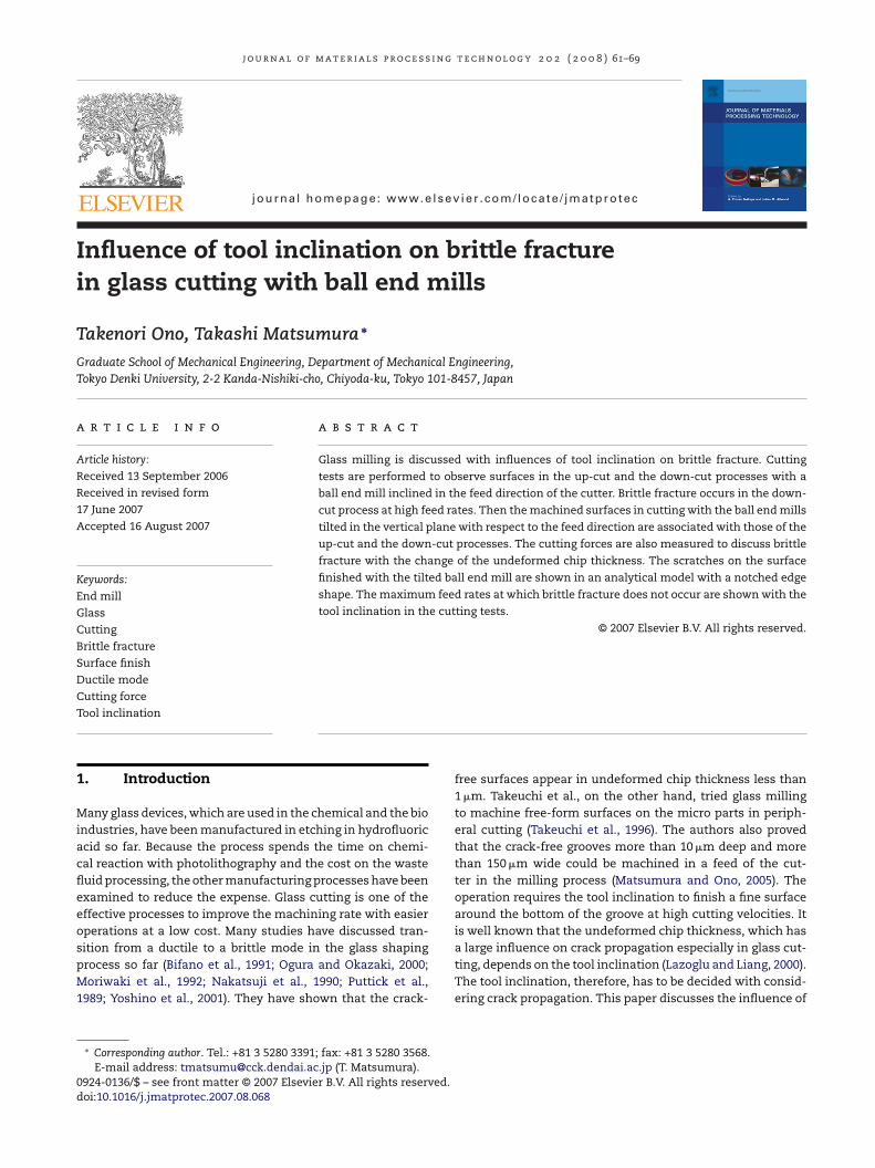
Fig. 1 – Cutting experiment. (a) Inclined ball end mill in thefeed direction. (b) Experiment setup.
the tool inclination on brittle fracture in glass milling with theball end mill. In order to associate with the up-cut and thedown-cut milling processes, this paper focuses on the cuttingprocesses with the tilted ball end mills, which are inclined in
Fig. 2 – Ball end mill used in cutting tests.
Fig. 3 – Cutting edge. (a) Rake face. (b) Cross-section ofcutting edge.
the vertical plane with respect to the direction of the cutterfeed. The maximum feed rates at which crack-free machiningcan be performed are shown with the tool inclination.
2. Brittle fracture in the milling process
The cutting tests are performed in machining with the ballend mills inclined at an angle of 45◦ in the direction of the
cutter feed as shown in Fig. 1. Brittle fracture is observed withincreasing the feed rate, where the spindle speed and the axialdepth of cut are 20,000 rpm and 0.02 mm, respectively. The1 mm thick plates of crown glass (72% SiO2, 18% K2CO2, 10%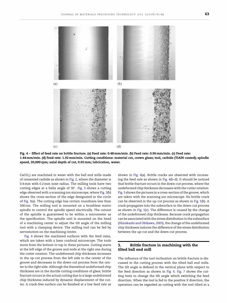
j o u r n a l o f m a t e r i a l s p r o c e s s i n g t e c h n o l o g y 2 0 2 ( 2 0 0 8 ) 61–69 63
Fig. 4 – Effect of feed rate on brittle fracture. (a) Feed rate: 0.48 mm/min. (b) Feed rate: 0.96 mm/min. (c) Feed rate:1 : mas ate
Co0ceso5sotots
wmatigttfct
.44 mm/min. (d) Feed rate: 1.92 mm/min. Cutting conditionspeed, 20,000 rpm; axial depth of cut, 0.02 mm; lubrication, w
aCO2) are machined in water with the ball end mills madef cemented carbide as shown in Fig. 2, where the diameter is.4 mm with 0.2 mm nose radius. The milling tools have twoutting edges at a helix angle of 30◦. Fig. 3 shows a cuttingdge observed with a scanning ion microscope, where Fig. 3(b)hows the cross-section of the edge designated in the circlef Fig. 3(a). The cutting edge has certain roundness less than00 nm. The milling tool is mounted on a brushless motorpindle to control the spindle speed electrically. The runoutf the spindle is guaranteed to be within a micrometer ashe specification. The spindle unit is mounted on the headf a machining center to adjust the tilt angle of the millingool with a clamping device. The milling tool can be fed byervomotors on the machining center.
Fig. 4 shows the machined surfaces with the feed rates,hich are taken with a laser confocal microscope. The toolsove from the bottom to top in these pictures. Cutting starts
t the left edge of the groove and ends at the right one duringhe cutter rotation. The undeformed chip thickness increasesn the up-cut process from the left side to the center of theroove and decreases in the down-cut process from the cen-er to the right side. Although the theoretical undeformed chip
hickness are in the ductile cutting conditions of glass, brittleracture occurs in the actual cutting due to a large undeformedhip thickness induced by dynamic displacement of the cut-er. A crack-free surface can be finished at a low feed rate asterial cut, crown glass; tool, carbide (TiAlN coated); spindler.
shown in Fig. 4(a). Brittle cracks are observed with increas-ing the feed rate as shown in Fig. 4(b–d). It should be noticedthat brittle fracture occurs in the down-cut process, where theundeformed chip thickness decreases with the cutter rotation.Fig. 5 shows the pictures in a cross-section of the groove, whichare taken with the scanning ion microscope. No brittle crackcan be observed in the up-cut process as shown in Fig. 5(b). Acrack propagates into the subsurface in the down-cut processas shown in Fig. 5(c). The difference is caused by the changeof the undeformed chip thickness. Because crack propagationcan be associated with the stress distribution in the subsurface(Shirakashi and Obikawa, 2003), the change of the undeformedchip thickness induces the difference of the stress distributionbetween the up-cut and the down-cut process.
3. Brittle fracture in machining with thetilted ball end mill
The influence of the tool inclination on brittle fracture is dis-cussed in the cutting process with the tilted ball end mills.The tilt angle is defined in the vertical plane with respect to
the feed direction as shown in Fig. 6. Fig. 7 shows the cut-ting tests to change the tilt angle which switching the feeddirection. When the tool is fed in the positive X direction, theoperation can be regarded as cutting with the tool tilted at a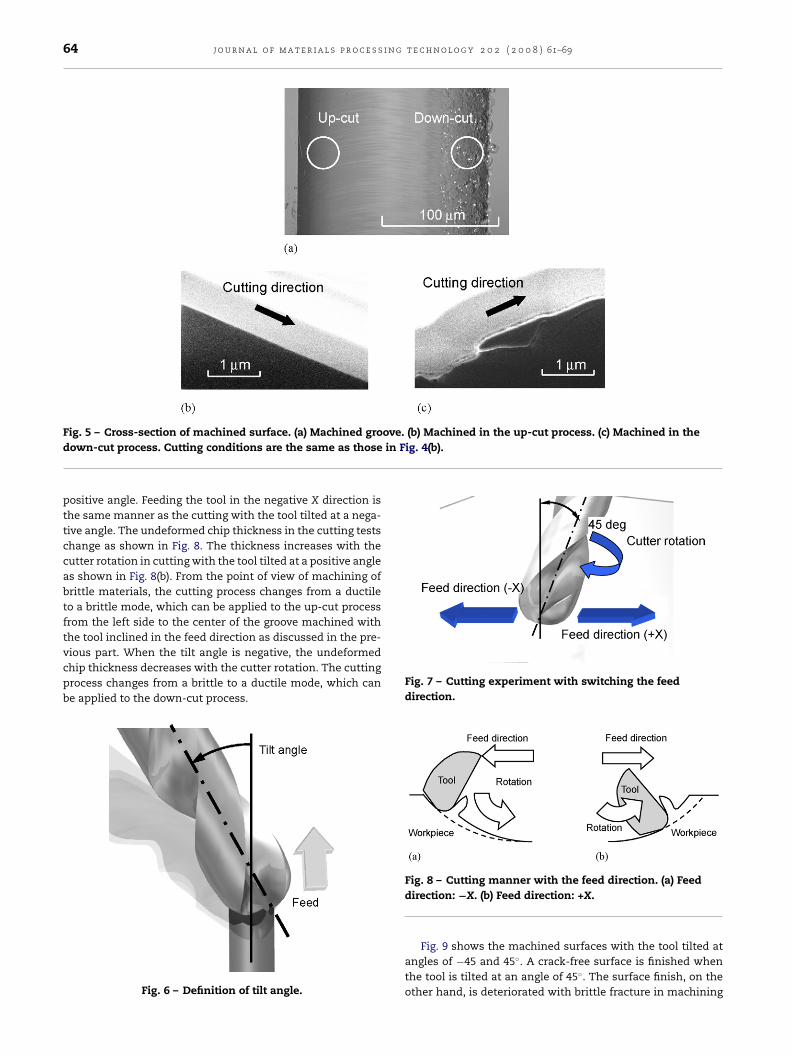
64 j o u r n a l o f m a t e r i a l s p r o c e s s i n g t e c h n o l o g y 2 0 2 ( 2 0 0 8 ) 61–69
Fig. 5 – Cross-section of machined surface. (a) Machined groove. (b) Machined in the up-cut process. (c) Machined in thein Fig. 4(b).
down-cut process. Cutting conditions are the same as thosepositive angle. Feeding the tool in the negative X direction isthe same manner as the cutting with the tool tilted at a nega-tive angle. The undeformed chip thickness in the cutting testschange as shown in Fig. 8. The thickness increases with thecutter rotation in cutting with the tool tilted at a positive angleas shown in Fig. 8(b). From the point of view of machining ofbrittle materials, the cutting process changes from a ductileto a brittle mode, which can be applied to the up-cut processfrom the left side to the center of the groove machined withthe tool inclined in the feed direction as discussed in the pre-
vious part. When the tilt angle is negative, the undeformedchip thickness decreases with the cutter rotation. The cuttingprocess changes from a brittle to a ductile mode, which canbe applied to the down-cut process.Fig. 6 – Definition of tilt angle.
Fig. 7 – Cutting experiment with switching the feeddirection.
Fig. 8 – Cutting manner with the feed direction. (a) Feeddirection: −X. (b) Feed direction: +X.
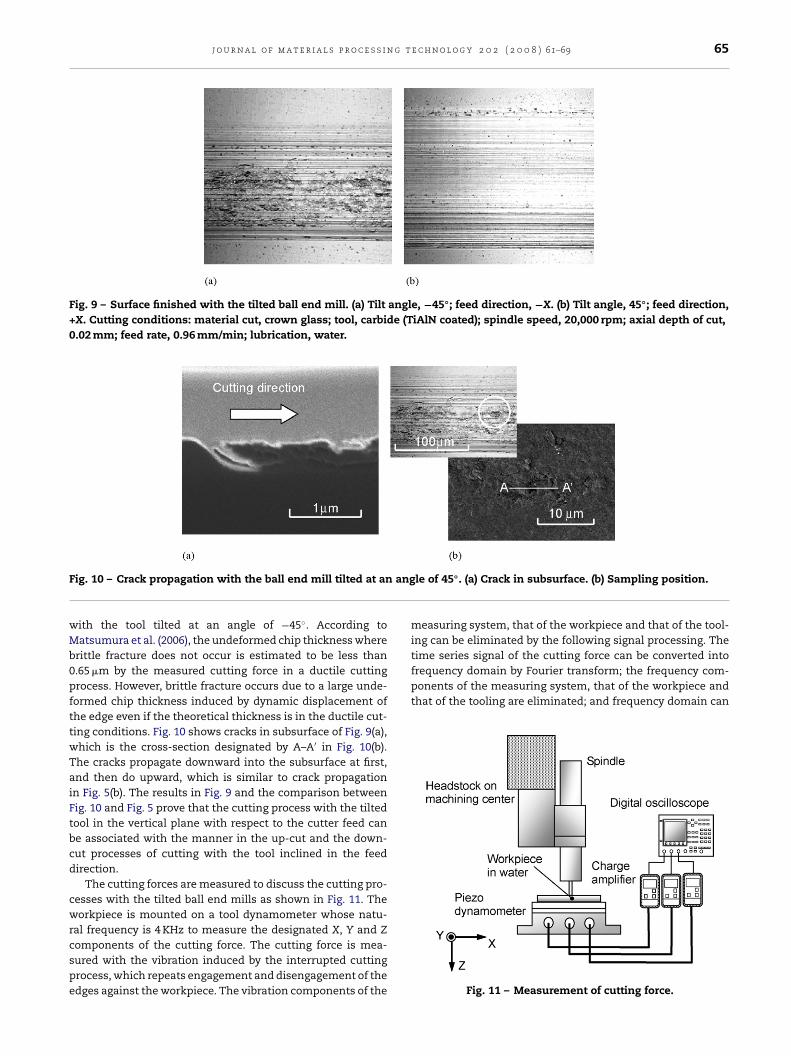
Fig. 9 shows the machined surfaces with the tool tilted atangles of −45 and 45◦. A crack-free surface is finished whenthe tool is tilted at an angle of 45◦. The surface finish, on theother hand, is deteriorated with brittle fracture in machining
j o u r n a l o f m a t e r i a l s p r o c e s s i n g t e c h n o l o g y 2 0 2 ( 2 0 0 8 ) 61–69 65
Fig. 9 – Surface finished with the tilted ball end mill. (a) Tilt angle, −45◦; feed direction, −X. (b) Tilt angle, 45◦; feed direction,+X. Cutting conditions: material cut, crown glass; tool, carbide (TiAlN coated); spindle speed, 20,000 rpm; axial depth of cut,0.02 mm; feed rate, 0.96 mm/min; lubrication, water.
F ang
wMb0pfttwTaiFtbcd
cwrcspe
time series signal of the cutting force can be converted intofrequency domain by Fourier transform; the frequency com-ponents of the measuring system, that of the workpiece andthat of the tooling are eliminated; and frequency domain can
ig. 10 – Crack propagation with the ball end mill tilted at an
ith the tool tilted at an angle of −45◦. According toatsumura et al. (2006), the undeformed chip thickness where
rittle fracture does not occur is estimated to be less than.65 �m by the measured cutting force in a ductile cuttingrocess. However, brittle fracture occurs due to a large unde-ormed chip thickness induced by dynamic displacement ofhe edge even if the theoretical thickness is in the ductile cut-ing conditions. Fig. 10 shows cracks in subsurface of Fig. 9(a),hich is the cross-section designated by A–A′ in Fig. 10(b).he cracks propagate downward into the subsurface at first,nd then do upward, which is similar to crack propagationn Fig. 5(b). The results in Fig. 9 and the comparison betweenig. 10 and Fig. 5 prove that the cutting process with the tiltedool in the vertical plane with respect to the cutter feed cane associated with the manner in the up-cut and the down-ut processes of cutting with the tool inclined in the feedirection.
The cutting forces are measured to discuss the cutting pro-esses with the tilted ball end mills as shown in Fig. 11. Theorkpiece is mounted on a tool dynamometer whose natu-
al frequency is 4 KHz to measure the designated X, Y and Z
omponents of the cutting force. The cutting force is mea-ured with the vibration induced by the interrupted cuttingrocess, which repeats engagement and disengagement of thedges against the workpiece. The vibration components of thele of 45◦. (a) Crack in subsurface. (b) Sampling position.
measuring system, that of the workpiece and that of the tool-ing can be eliminated by the following signal processing. The
Fig. 11 – Measurement of cutting force.
66 j o u r n a l o f m a t e r i a l s p r o c e s s i n g
Fig. 12 – Cutting force in machining with the tilted ball endmill. (a) Tilt angle, −45◦; feed direction, −X. (b) Tilt angle,45◦; feed direction, +X. Cutting conditions are the same as
finished with the tool inclined at a lead angle is discussedby Matsumura and Ono (2008). This paper presents anothermodel in machining with the tilted ball end mill. Fig. 13 showsthe cutting process with the tilted ball end mill, where the
those in Fig. 9.
be converted into the time series signal by inverse Fouriertransform.
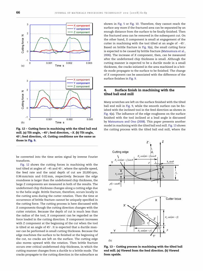
Fig. 12 shows the cutting forces in machining with thetool tilted at angles of −45 and 45◦, where the spindle speed,the feed rate and the axial depth of cut are 20,000 rpm,0.96 mm/min and 0.02 mm, respectively. Because the edgeroundness is larger than the undeformed chip thickness, thelarge Z components are measured in both of the results. Theundeformed chip thickness changes along a cutting edge dueto the helix angle. Brittle fracture, therefore, occurs locally inthe cutting area during the cutter rotation. Then the time atoccurrence of brittle fracture cannot be uniquely specified inthe cutting force. The cutting process is here discussed withX components though the cutting direction changes with thecutter rotation. Because the depth of cut is much less thanthe radius of the tool, X component can be regarded as theforce loaded in the cutting direction. X component increaseswith Z component at the beginning of the cut when the toolis tilted at an angle of 45◦. It is expected that a ductile man-ner can be performed in small cutting thickness. Because theedge machines the surface to be finished at the beginning ofthe cut, no cracks are left on the surface. The cutting edge
also moves upward with the rotation. Then brittle fractureoccurs over critical undeformed chip thickness, in which thecutting manner changes from a ductile to a brittle mode. Thecracks propagate to the cutting direction in the subsurface ast e c h n o l o g y 2 0 2 ( 2 0 0 8 ) 61–69
shown in Fig. 5 or Fig. 10. Therefore, they cannot reach thesurface any more if the fractured area can be separated by anenough distance from the surface to be finally finished. Thenthe fractured area can be removed in the subsequent cut. Onthe other hand, X component is small at engagement of thecutter in machining with the tool tilted at an angle of −45◦.Based on brittle fracture in Fig. 9(a), the small cutting forceis expected to be caused by brittle fracture (Matsumura et al.,2006). The increase of X component, then, can be measuredafter the undeformed chip thickness is small. Although thecutting manner is expected to be a ductile mode in a smallthickness, the cracks initiated in the area machined in a brit-tle mode propagate to the surface to be finished. The changeof X component can be associated with the difference of thesurface finishes in Fig. 9.
4. Surface finish in machining with thetilted ball end mill
Many scratches are left on the surface finished with the tiltedball end mill in Fig. 9, while the smooth surface can be fin-ished with the inclined tool in the feed direction as shown inFig. 4(a). The influence of the edge roughness on the surface
Fig. 13 – Cutting process in machining with the tilted ballend mill. (a) Viewed from the feed direction. (b) Viewedfrom upside.
g t e c h n o l o g y 2 0 2 ( 2 0 0 8 ) 61–69 67
btwow
wiocd
R
ig
R
w(
F
j o u r n a l o f m a t e r i a l s p r o c e s s i n
all nose radius is �. The milling tool moves in the X direc-ion. X′–Y′–Z′ is the coordinate system inclined at the angle �,hich rotates with the cutting edge. Position P at a height hp
n a cutting edge rotating at the angular velocity ω is givenith the time t as follows:
xP = ft + RP sin(ωt − �)
yP = hP sin � + RP cos(ωt − �) cos �
zP = −Ad + �(1 − cos �) + hP cos � − RP cos(ωt − �) sin �
⎫⎪⎬⎪⎭ (1)
here f and Ad are the feed rate and the axial depth of cut. �
s the delay angle of point P referred to the edge at the bottomf the cutter, which is associated with the helix angle and theutter height. Rp is the rotating radius at position P, which isefined as a function of the cutter height hp:
p = J(hp) (2)
A notched edge is defined as a simple model to show thenfluence of the edge roughness on the surface profile. Rp isiven as follows:
√
p = �2 − (� − hp)2 − A + (−1)(int)(hp/�)A (3)here A and � are the amplitude and the pitch of the notches.int)(hp/�) takes integer part of (hp/�). Fig. 14 shows an example
ig. 14 – Notched edge. (a) Edge shape. (b) Magnified edge.
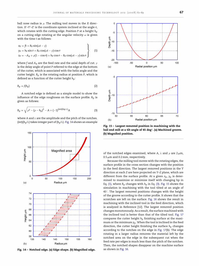
Fig. 15 – Largest removed position in machining with theball end mill at a tilt angle of 45 deg◦. (a) Machined groove.(b) Magnified position.
of the notched edges examined, where A, � and � are 2 �m,0.5 �m and 0.2 mm, respectively.
Because the milling tool moves with the rotating edges, thesurface profile in the cross section changes with the positionin the feed direction. The largest removed positions in the Ydirection at each Z are here projected on Y–Z plane, which aredifferent from the surface profile. At a given zp, yp is deter-mined to maximize or minimize itself with changing hp inEq. (1), where Rp changes with hp in Eq. (3). Fig. 15 shows thesimulation in machining with the tool tilted at an angle of45◦. The largest removed positions changes with the heightof the groove according to the cutter profile. It shows that thescratches are left on the surface. Fig. 16 shows the result inmachining with the inclined tool in the feed direction, whichis analyzed in Reference [12]. The largest removed positionchanges monotonously. As a result, the surface machined withthe inclined tool is better than that of the tilted tool. Fig. 17compares the cutter height hp finishing surface at the maxi-mum or the minimum yp. When the tool is inclined in the feeddirection, the cutter height finishing the surface hp changesaccording to the notches on the edge in Fig. 17(b). The edgerotating in a larger radius removes the material left by thenotched area on the edge in the subsequent cut when thefeed rate per edges is much less than the pitch of the notches.
Then, the notched shapes disappear on the machine surfaceas shown in Fig. 16.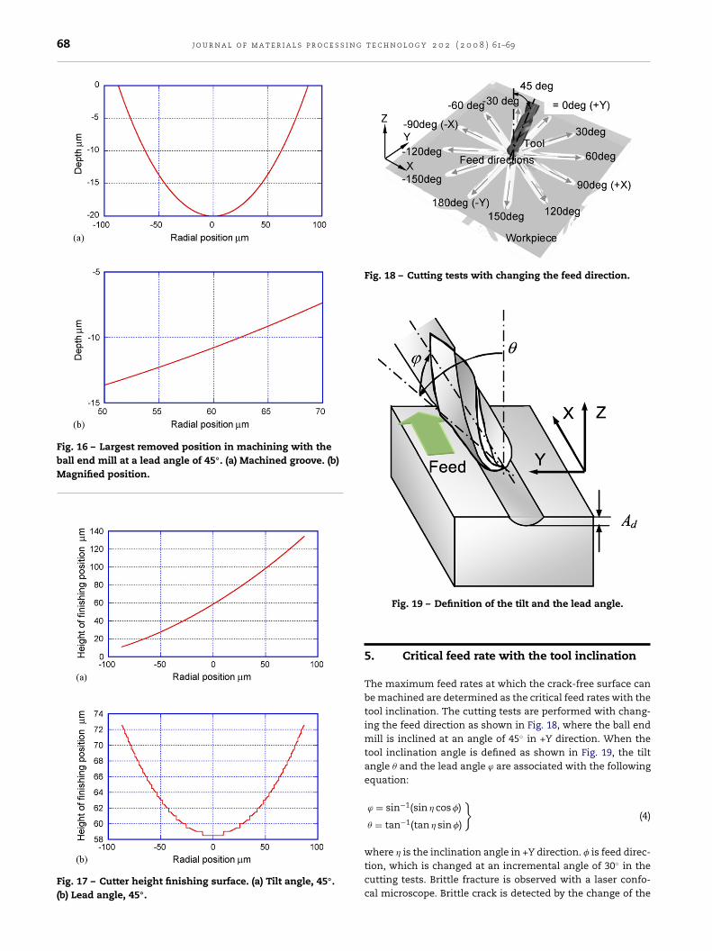
68 j o u r n a l o f m a t e r i a l s p r o c e s s i n g t e c h n o l o g y 2 0 2 ( 2 0 0 8 ) 61–69
Fig. 16 – Largest removed position in machining with theball end mill at a lead angle of 45◦. (a) Machined groove. (b)Magnified position.
Fig. 17 – Cutter height finishing surface. (a) Tilt angle, 45◦.(b) Lead angle, 45◦.
Fig. 18 – Cutting tests with changing the feed direction.
Fig. 19 – Definition of the tilt and the lead angle.
5. Critical feed rate with the tool inclination
The maximum feed rates at which the crack-free surface canbe machined are determined as the critical feed rates with thetool inclination. The cutting tests are performed with chang-ing the feed direction as shown in Fig. 18, where the ball endmill is inclined at an angle of 45◦ in +Y direction. When thetool inclination angle is defined as shown in Fig. 19, the tiltangle � and the lead angle ϕ are associated with the followingequation:
ϕ = sin−1(sin � cos )
� = tan−1(tan � sin )
}(4)
where � is the inclination angle in +Y direction. is feed direc-tion, which is changed at an incremental angle of 30◦ in thecutting tests. Brittle fracture is observed with a laser confo-cal microscope. Brittle crack is detected by the change of the
j o u r n a l o f m a t e r i a l s p r o c e s s i n g t
dst0wawstb
6
TbTiTwict
ctrg
r
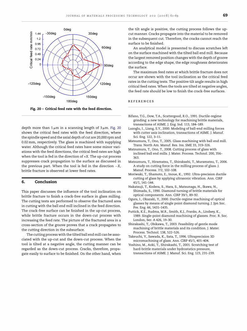
Fig. 20 – Critical feed rate with the feed direction.
epth more than 1 �m in a scanning length of 3 �m. Fig. 20hows the critical feed rates with the feed direction, wherehe spindle speed and the axial depth of cut are 20,000 rpm and.02 mm, respectively. The glass is machined with supplyingater. Although the critical feed rates have some minor vari-
tions with the feed directions, the critical feed rates are highhen the tool is fed in the direction of +X. The up-cut process
uppresses crack propagation to the surface as discussed inhe previous part. When the tool is fed in the direction −X,rittle fracture is observed at lower feed rates.
. Conclusion
his paper discusses the influence of the tool inclination onrittle fracture to finish a crack-free surface in glass milling.he cutting tests are performed to observe the fractured area
n cutting with the ball end mill inclined in the feed direction.he crack-free surface can be finished in the up-cut process,hile brittle fracture occurs in the down-cut process with
ncreasing the feed rate. The picture of the fractured area in aross-section of the groove proves that a crack propagates tohe cutting direction in the subsurface.
The cutting process with the tilted ball end mill can be asso-
iated with the up-cut and the down-cut process. When theool is tilted at a negative angle, the cutting manner can beegarded as the down-cut process. Cracks, therefore, propa-ate easily to surface to be finished. On the other hand, whene c h n o l o g y 2 0 2 ( 2 0 0 8 ) 61–69 69
the tilt angle is positive, the cutting process follows the up-cut manner. Cracks propagate into the material to be removedin the subsequent cut. Therefore, the cracks cannot reach thesurface to be finished.
An analytical model is presented to discuss scratches lefton the surface machined with the tilted ball end mill. Becausethe largest removed position changes with the depth of grooveaccording to the edge shape, the edge roughness deterioratesthe surface.
The maximum feed rates at which brittle fracture does notoccur are shown with the tool inclination as the critical feedrates in the cutting tests. The positive tilt angle results in highcritical feed rates. When the tools are tilted at negative angles,the feed rate should be low to finish the crack-free surfaces.
e f e r e n c e s
Bifano, T.G., Dow, T.A., Scattergood, R.O., 1991. Ductile-regimegrinding: a new technology for machining brittle materials,transactions of ASME. J. Eng. Ind. 113, 184–189.
Lazoglu, I., Liang, S.Y., 2000. Modeling of ball-end milling forceswith cutter axis inclination, transactions of ASME. J. Manuf.Sci. Eng. 122, 3–11.
Matsumura, T., Ono, T., 2005. Glass machining with ball end mill.Trans. North Am. Manuf. Res. Ins. SME 33, 319–326.
Matsumura, T., Ono, T., 2008. Cutting process of glass withinclined ball end mills. J. Mater. Process. Technol. 200, 356–363.
Matsumura, T., Hiramatsu, T., Shirakashi, T., Muramatsu, T., 2006.A study on cutting force in the milling process of glass. J.Manuf. Process. 7/2, 102–108.
Moriwaki, T., Shamoto, E., Inoue, K., 1992. Ultra-precision ductilecutting of glass by applying ultrasonic vibration. Ann. CIRP41/1, 141–144.
Nakatsuji, T., Kodera, S., Hara, S., Matsunaga, H., Ikawa, N.,Shimada, S., 1990. Diamond turning of brittle materials foroptical components. Ann. CIRP 39/1, 89–92.
Ogura, I., Okazaki, Y., 2000. Ductile-regime machining of opticalglasses by means of single point diamond turning. J. Jpn Soc.Pre. Eng. 66, 1431–1435.
Puttick, K.E., Rudma, M.R., Smith, K.J., Franks, A., Lindsey, K.,1989. Single-point diamond machining of glasses. Proc. R. Soc.London, Ser. A 426, 19–30.
Shirakashi, T., Obikawa, T., 2003. Feasibility of gentle modemachining of brittle materials and its condition. J. Mater.Process. Technol. 138, 522–526.
Takeuchi, Y., Sawada, K., Sata, T., 1996. Ultraprecision 3Dmicromachining of glass. Ann. CIRP 45/1, 401–404.
Yoshino, M., Aoki, T., Shirakashi, T., 2001. Scratching test ofhard-brittle materials under hydrostatics pressure,transactions of ASME. J. Manuf. Sci. Eng. 123, 231–239.