Embed Size (px)
Citation preview

S50
Influence of welding method on microstructural creation of welded joints
P. Čičo1, D. Kalincová2, M. Kotus1
1Faculty of Engineering, Slovak University of Agriculture in Nitra, Nitra, Slovak Republic2Faculty of Environmental and Manufacturing Technology, Technical University in Zvolen,
Zvolen, Slovak Republic
Abstract
Čičo P., Kalincová D., Kotus M., 2011. Influence of welding method on microstructural creation of welded joints. Res. Agr. Eng., 57 (Special Issue): S50–S56.
This paper is focused on the analysis of the welding technology influence on the microstructure production and quality of the welded joint. Steel of class STN 41 1375 was selected for the experiment, the samples were welded by arc welding including two methods: a manual one by coated electrode and gas metal arc welding method. Macro and microstructural analyses of the experimental welded joints confirmed that the welding parameters affected the welded joint structure in terms of the grain size and character of the structural phase.
Keywords: thermal field; arc welding; coated electrode; gas metal arc welding GMAW (method); metallographical analysis
Supported by the Scientific Grant Agency VEGA of the Ministry of Education of the Slovak Republic and the Slovak Academy of Sciences, Grant No. 1/0511/08.
Welding is a production technology of non-de-mountable joints of two materials, whose principal mechanical or structural attributes succumb to the changes of the temperature influence from molten weld metal. The welded joint becomes heterogeneous part of the construction. Manufacturing degradation is brought into the parent material by welding; there-fore, the individual welded joints have to be control-led by the standard STN EN ISO 15614-1 (2005) for the proposal of the welding way and parameters.
The tests of the joint welding, following this standard, are divided into non-destructive and destructive. The integrity, mechanical properties, and structure are mostly controlled. Every welding method is characterised by specific effects on the parent material in terms of the heat generated the welding process. The impact of the thermal chang-es resides in the changes of the properties in the
welded joints zone. These depend on the chemical composition, material thickness, joint shape, weld-ing conditions, but also on the physical characteris-tics of the welded materials (heat conduction, spe-cific heat, etc.).
Heat input, heat field and heat cycle
Heat source causes changes of the joint materials temperature depending on the time and location in relation to the heat source in welding. The temper-ature distribution depending on time is called heat field. It can be calculated by means of differential equations of the heat conductance in solid bodies.
Rosenthal (1946) and Rykalin (1957) suggested its calculation for point linear movement of the source by Eq. (1) of the heat conductance in solid state.
Vol. 57, 2011 (Special Issue): S50–S56 Res. Agr. Eng.

S51
(1)
where: x, y, z – coordinates of the location T – temperature (K)
(2)
whre: λ – coefficient of heat conductanceρ × c – volume heat capacity (J/m3 K)
Thermal changes caused by electrical arc welding are characteristic by high speed of heating and cool-ing and the temperature gradient depending on the distance from the weld. The temperature changes of one spot of the welded joint depending on time characterise the heat cycle of the welding, that is the time change of temperature (Fig. 1) (Brziak et al. 2003). The structure formation of the welded joint significantly relates to the welding method se-lection because the given heat input increases pro-portionally with voltage and welding current which depend on the way of welding.
Different combinations of voltage and current (e.g. U = 24 V, I = 82 A) are used in manual electri-cal arc welding as compared to the welding method gas metal arc welding (GMAW) (e.g. U = 18–35 V, I = 120–380 A). There are also differences in the welding speed.
The thickness of the welded materials affects the speed of the weld cooling and also the transforma-tional processes in austenitic structure of the heated heat affected zone (HAZ) of the parent material. Therefore, the final structure of the welded joint as a unit depends on whether the heat dissipation is two
or three dimensional. The cooling speed of the weld-ed sheet metal at two-dimensional heat dissipation (Fig. 2) depends on the thickness. The cooling speed at three-dimensional heat dissipation (Fig. 2) does not depend on the thickness of the sheet metal. The time of cooling t8/5, which is calculated by means of Uwer and Degenkolbe (1976) equation for the in-dividual ways of welding, is very important within the structural formation in HAZ.
For example, for three-dimensional heat dissipation:
(3)
where: F3 – factor of the weld shapeK3 – proportional coefficient of heat dissipation Q – heat input T0 – parent material temperature t8/5 – time of cooling
The boundary between two-dimensional and three-dimensional heat dissipation is formed by the so called transition thickness.
Structure of welded joint
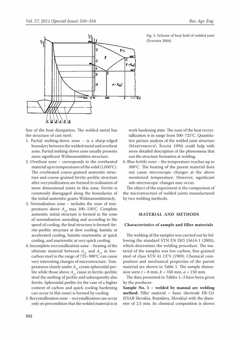
Primary crystallisation of low-carbon and me-dium-carbon steel appears at a larger degree or a smaller degree peritecticly. The fact that secondary crystallisation can also develop in the dendrites and can get within the dendrites to boundary movement immediately after their formation leads to connec-tions, which are not observable at the first sight. The structure of HAZ welded steel connects to phase bal-ance in system Fe-Fe3C. Fig. 3 illustrates the scheme of the heat field created in the joint vicinity at weld-ing. Significant heat intervals 1–7 effective for low-carbon steel are derived from Fe-Fe3C diagram. Ac-cording to the initiate scheme for low-carbon steel welding, the following zones are distinguished in the heat impacted area (Štifner 2004):
Weld metal – its structure formats by cooling of the melt at a temperature of about 1,500°C, crystals of columnar type are formatted preferentially in the
Fig. 1. Heat cycle of welding (Brziak et al. 2003)Fig. 2. Scheme of two-dimensional (left) and three-dimen-sional (right) heat dissipation
tT
azT
yT
xT 1
2
2
2
2
2
2
ca
300
35/8 )800
1500
1( FTT
QKt
Res. Agr. Eng. Vol. 57, 2011 (Special Issue): S50–S56
S52
line of the heat dissipation. The welded metal has the structure of cast steel. 1. Partial melting-down zone – is a sharp-edged
boundary between the welded metal and overheat zone. Partial melting-down zone usually presents more significant Widmannstätten structure.
2. Overheat zone – corresponds to the overheated material up to temperatures of the solid (1,050°C). The overheated coarse-grained austenitic struc-ture and coarse-grained ferrite-perlitic structure after recrystallization are formed in realisation of more dimensional joints in this zone. Ferrite is commonly disengaged along the boundaries of the initial austenitic grains Widmannstättenicly.
3. Normalisation zone – includes the zone of tem-peratures above Ac3 max 100–150°C. Complete austenitic initial structure is formed in the zone of normalisation annealing and according to the speed of cooling, the final structure is formed: fer-rite-perlitic structure at slow cooling, bainitic at accelerated cooling, bainitic-martensitic at quick cooling, and martensitic at very quick cooling.
4. Incomplete recrystallization zone – heating of the ultimate material between Ac1 and Ac3 in low-carbon steel in the range of 725–900°C can cause very interesting changes of microstructure. Tem-peratures closely under Ac1 create spheroidal per-lite while those above Ac1 cause in ferrite-perlitic steel the melting of perlite and subsequently also ferrite. Spheroidal perlite (in the case of a higher content of carbon and quick cooling hardening can occur in this zone) is formed by cooling.
5. Recrystallization zone – recrystallization can occur only on precondition that the welded material is in
work hardening state. The zone of the heat recrys-tallization is in range from 500–725°C. Quantita-tive picture analysis of the welded joint structure (Martinkovič, Šugár 1994) could help with more detailed description of the phenomena that run the structure formation at welding.
6. Blue brittle zone – the temperature reaches up to 500°C. The heating of the parent material does not cause microscopic changes at the above mentioned temperature. However, significant sub-microscopic changes may occur.
The object of the experiment is the comparison of the microstructure of welded joints manufactured by two welding methods.
MAterIAl AnD MetHoDS
Characteristics of sample and filler materials
The welding of the samples was carried out by fol-lowing the standard STN EN ISO 15614-1 (2005), which determines the welding procedure. The ma-terial of the samples was low-carbon, fine-grained steel of class STN 41 1375 (1989). Chemical com-position and mechanical properties of the parent material are shown in Table 1. The sample dimen-sion were t = 8 mm, b = 350 mm, a = 150 mm.
The data presented in Tables 1–3 have been given by the producer.Sample no. 1 – welded by manual arc welding method: Filler material – basic electrode EB-121 (ESAB Slovakia, Bratislava, Slovakia) with the diam-eter of 2.5 mm. Its chemical composition is shown
Fig. 3. Scheme of heat field of welded joint (Štifner 2004)
Vol. 57, 2011 (Special Issue): S50–S56 Res. Agr. Eng.

S53
in Table 2. The electrode is one of those most used for the welding of significantly stressed components of energy pipes of devices, transport, pressure vessels, shipping and building constructions of up to Rm = 480 MPa. Welding parameters: U = 24 V, I = 82 A.Sample no. 2 – welded by GMAW method: Filler material – welding wire OK Autrod 12.58 (ESAB Slovakia, Bratislava, Slovakia), with the diameter of 1.2 mm. Chemical composition and mechanical properties are shown in Table 3. The wire is used for welding of the most common non-alloy and fine-grained structural steel with the yield strength limit of up to 380 MPa. It is suitable for the weld-ing of constructions, pressure vessels, shipping components, and also parts from galvanised sheet metal. It allows welding by high-voltage current (spray transfer) and also by short arc in all posi-tions. Welding parameters: U = 30 V, I = 220 A.
The drafts of the ample shape and location of sam-pling for the tests according to STN EN 15614-1 (2005) are illustrated in Fig. 4.
reSultS AnD DISCuSSIon
Figs 5 and 6 illustrate the documented mac-rostructure of the monitored samples.
The boundary of the melting-down was not very noticeable; the root was overheated but the weld ex-ceed was not sufficient in sample No. 1 (Fig. 5). The boundary of the melting-down was sharper; the sam-ple root was not overheated in sample No. 2 (Fig. 6).
Figs 7 and 8 illustrate the documented micro-structure of the welded metal sample.
The structure of sample No. 1 was more coarse-grained than that of sample No. 2. This was caused by acicular ferrite (AF), fine acicular ferrite (CAF) was bordered by more coarse ferrite at the bound-aries of the initial austenitic grains, which grew along the heat dissipation (Figs 7 and 8).
Figs 9 and 10 illustrate the comparison of the boundary zones of the samples melting-down.
The boundary of the sample No. 1 melting-down was not so noticeable as with sample No. 2.
Fig. 4. (a) Sample disc with butt joint with re-weld; (b) example of sampling for test ac-cording to standard (6 – spot of sampling for microscopic analysis)
Table 1. Chemical composition and mechanical properties of steel STN 41 1375
C (%) P (%) S (%) N (%) Fracture limit Yield limit
max 0.17 max 0.045 max 0.045 max 0.09 340–470 MPa 215 MPa
Table 2. Chemical composition of electrode EB-121
C (%) Mn (%) Si (%) P (%) S (%) N (%)
0.05 0.80 0.40 – – –
Table 3. Parameters of welding wire OK Autrod 12.58
C (%) Mn (%) Si (%) Gas Rm (MPa) Re (MPa)
0.10 1.10 0.65M21 515 420
C1 485 375
(a) (b)
Res. Agr. Eng. Vol. 57, 2011 (Special Issue): S50–S56

S54
Figs 11 and 12 illustrate the documented high-heated zone affected after transformation.
The microstructure of this part of HAZ was formed by upper bainite (UB) and acicular ferrite (AF) along the boundary of austenitic grains after austenite disintegration, which had locally Wid-mannstättenic character. In sample No. 1, this zone was more coarse-grained than in sample No. 2. The roughness of austenitic grain in HAZ heated in the zone of high temperatures formats the more coarse structures after its transformation at cooling, which was noticed in lower values of the mechanical attributes, particularly ductility in this part of joint.
Figs 13 and 14 illustrate the documented zones affected by the heat closely above Ac3. The structure was more fine-grained than with high-heated HAZ, and was formed by acicular ferrite (AF, CAF) and lower bainit (LB).
Sample No. 1 shows also non-metallic inclusions. Figs 15 and 16 show the comparison between the
sample zones after heating at a temperature below A1, where the structural changes were not noticed to origin state (in comparison with the original state).
The structure of the parent sample material was fine-grained, ferrite-perlitic. The divergences in the grain size related to small inhomogeneity of the plate sheet metal, from which the samples were taken. The results of the structural analysis of micro-scratch pattern samples of welds made by manual electrical arc welding and GMAW method and the evaluation of macro-scratch pattern of welds correspond to the knowledge of the welding method used.
The amount of heat brought into the weld in the course of manual electrical arc welding is higher than that GMAW method. The welding speed in manual electrical arc welding is lower, therefore a greater volume of the weld metal, deeper penetra-tion, a wider zone of the overheated material, and higher heat inertia of the heated material volume are noticed. Cooling is slower and that formats grain coarsening with the related mechanical attribute decrement of the material in the welding zone. From this point of view, we can assess GMAW meth-od as positive. The range of HAZ is about 20% to 30% narrower with GMAW method by using opti-mal parameters of welding at manual electrical arc welding and GMAW.
Fig. 5. Sample No. 1 (Mag. 12.5×)1 – weld metal, 2 – melting-down boundary, 3 – HAZ, 4 – HAZ
Fig. 6. Sample No. 2 (Mag. 10×)
Fig. 7. Microstructure of welding metal – Sample No. 1 Fig. 8. Microstructure of welding metal – Sample No. 2
Vol. 57, 2011 (Special Issue): S50–S56 Res. Agr. Eng.

S55
Fig. 9. Microstructure of melting-down boundary – Sample No. 1
Fig. 10. Microstructure of melting-down boundary – Sam-ple No. 2
Fig. 11. Microstructure of high-heated HAZ – Sample No. 1
Fig. 12. Microstructure of high-heated HAZ – Sample No. 2
Fig. 13. Microstructure HAZ – Sample No. 1 Fig. 14. Microstructure HAZ – Sample No. 2
The boundary of melting-down at manual arc welding is not noticeable and geometric, which is caused by the character of the manual electrical arc welding, electrode diameter, and movement of the electrode spike, possibly due to electric arc
blowing. In consideration of the controlled electric arc in GMAW method and better geometry in the process kinematics, the geometry of the weld bead is symmetrical, the welded metal bound, and the welds geometry univocally definable.
Res. Agr. Eng. Vol. 57, 2011 (Special Issue): S50–S56

S56
ConCluSIon
The paper was focused on the analysis of the ef-fects of welding technologies on the welded joint microstructure quality and formation. The samples tested came from the material class STN 41 1375 (1989) and were welded using the technologies of the manual electrical arc welding and of GMAW. The analyses of macro and microstructures of the welded joints confirmed that the technologies and technological parameters of welding influence the structure of the welded joint and range of the mate-rial affected by welding. From this point of view, the differential approach to the selection of progressive welding method is very important, particularly considering the heat input and other factors posi-tively affecting the results of the welding process.
r e f e r e n c e s
Brziak P., Bernasovský P., Mráz Ľ., Piussi V., Grgáč P., Mráz Ľ., Hrivňák I., Kálna K., Pecha J., Országhová J., Blaškovitš P., Balla J., Meško J., Országh V., 2003. Materiály a ich správanie sa pri zváraní – 2. kniha učebných textov pre kurzy zváračských inžinierov (Materials and their Behaviour at Surfacing Welding – 2nd Study Book for Courses of Welding Engineers). 2nd Ed. Bratislava, Welding Research Institute, PI SR.
Martinkovič M., Šugár P., 1994. Automation of materials structure analysis. In: DAAAM Symphosium. Maribor, Slovenia, DAAAM International Vienna: 269–270.
Rosenthal D. 1946. Theory of moving sources of heat and its application to metal treatments. Transactions of the ASME, 68: 849–866.
Rykalin N.N. 1957. Berechneung der Wärmevorgänge beim Schweissen (Calculation of Heat Impact at Welding). Ber-Ber-lin, VEB Verlag Technik.
STN 41 1375, 1989. Oceľ 11 375 (Steel 11 375). STN EN ISO 15614-1, 2005. Stanovenie a schválenie postupov
zvárania kovových materiálov. Skúška postupu zvárania. Časť 1: Oblúkové a plameňové zváranie ocelí a oblúkové zváranie niklu a niklových zliatin (Specification and qualifi-cation of welding procedures for metallic materials. Weld-ing procedure test. Part 1: Arc and gas welding of steels and arc welding of nickel and nickel alloys).
Štifner T., 2004. Kovové materially (Metallic materi-als). Available at www.stifner.sk/skola/doc/afm/texty_AFM_2004.doc (accessed November 22, 2008)
Uwer D., Degenkolbe J., 1976. Temperaturzyklen beim Lichtbogenschweissen. Journal de la Soudure/Zeitschrift für Schweisstechnik, 4: 73–88.
Received for publication December 11, 2010 Accepted after corrections May 5, 2011
Fig. 15. Microstructure HAZ – Sample No. 1
Corresponding author:
Ing. Martin Kotus, Ph.D., Slovak University of Agriculture in Nitra, Faculty of Engineering, Department of Quality and Engineering Technologies, Tr. A. Hlinku 2, 949 76 Nitra, Slovak Republic e-mail: [email protected]
Fig. 16. Microstructure HAZ – Sample No. 2
Vol. 57, 2011 (Special Issue): S50–S56 Res. Agr. Eng.