Embed Size (px)
Citation preview
INFLUENCE STUDY OF ACTUATION CONDITIONS OF PASSIVE SAFETY SYSTEM ON SGTR
Zijiang YANG School of Nuclear Science and Technology, Xi’an
Jiaotong University Xi’an, Shaanxi Province, China
Jianqiang SHAN School of Nuclear Science and Technology, Xi’an
Jiaotong University Xi’an, Shaanxi Province, China
Junli GOU School of Nuclear Science and Technology, Xi’an
Jiaotong University Xi’an, Shaanxi Province, China
ABSTRACT As the development of the nuclear industry, passive
technology turns out to be a remarkable characteristic in the
design of advanced nuclear power plants. Since the 20th
century, much effort has been given to the passive technology,
and a number of evolutionary passive systems have developed.
The CPR1000 plant, which is one kind of mature
pressurized water plants in China, is proposed to be improved
with some passive systems to enhance safety. The proposed
passive systems include: (1) the RMT (reactor makeup tank);
(2) the A-ACC (advanced accumulators); (3) the IRWST (in-
containment refueling water storage tank); (4) the PEFS
(passive emergency feed water system), which is installed on
the secondary side of SGs; (5) the PDS (passive
depressurization system).
In designing the passive safety system, we found that the
actuation conditions of the passive safety system bring a great
effect on the accidental mitigation. It was necessary to study the
influence induced by them. In this paper, the transient
phenomenon of SGTR was analyzed to show the method in
modification of the actuation conditions. The reason of
choosing SGTR was to demonstrate the great impact induced by
the PEFS.
KEYWORDS passive safety system; CPR1000; modification; actuation
conditions
1. INTRODUCTION Passive safety systems are widely used nowadays to
enhance the safety of the reactors. According to IAEA report,
the passive technologies are those utilize natural forces, such as
gravity and natural circulation. And the passive safety systems
should be composed entirely of passive components and
structures(Juhn et al., 2000). The advantages of the passive
safety systems can be summarized as (1) independent on
pumps or external power (Nayak and Sinha, 2007); (2) ruling
out human errors; and (3) more economical.
The passive safety systems are widely applied on advanced
reactor designs such as the AP1000 in the USA, the Next
Generation PWR in Japan, the WWER-1000 (Timofeev and
Karzov, 2006) in Russia, the ESBWR in the Europe and so on.
Among them, the AP1000 (Sutharshan et al., 2011) adopts an
entirely passive safety system. Its technology is relatively
mature. The Nest Generation PWR (Tujikura et al., 2000) is
equipped with a passive safety system which acts as backups to
prevent core damage. The APR1400 (Kim and Kim, 2002) in
Korea applied several passive systems including advanced
accumulator. Unlike AP1000, the APR1400 adopts a secondary
passive heat removal system, which is also used to improve the
CPR1000 technology (Zhang et al., 2011). As for the passive
containment cooling system, C.S. Byun (Byun et al., 2000)
designed a semi-passive containment cooling system for a large
concrete containment and Mirela Gavrilas (Gavrilas et al.,
Proceedings of the 2016 24th International Conference on Nuclear Engineering ICONE24
June 26-30, 2016, Charlotte, North Carolina
ICONE24-61053
1 Copyright © 2016 by ASME
2000) designed a passively cooled containment for a high-rating
pressurized water reactor.
In this paper, we discussed the method in modifying the
actuation conditions of a passive safety system designed for
CPR1000. Due to the application of the passive safety system,
the standard assumptions of the CPR1000 during the accidents
were not proper any more. Thus, the accidental assumptions
should be adjusted so that the accident could result in the most
dangerous accidental transient phenomenon. With the most
dangerous assumptions, some sensitivity analyses were needed
to determine the proper actuation conditions of the safety
system to make sure that it mitigates the accident and keeps the
reactor’s safety. In this paper, the process of actuation
conditions’ modification during SGTR was presented. SGTR
was considered as one of the design basis accidents having a
significant impact on safety in a viewpoint of radiological
release (Jiang et al., 2010; Park et al., 2013). The reason of
choosing this accident was that the application of PEFSs greatly
affected the transient phenomenon during SGTR, which
attracted much research interest (Kang et al., 2006; Kang et al.,
2012; Lee et al., 2011).
2. DESCRIPTION OF THE PASSIVE SAFETY SYSTEM The components of the passive safety system are as
follows: (1) the RMTs (reactor makeup tank); (2) the A-ACCs
(advanced accumulator); (3) the IRWST (in-containment
refueling water storage tank); (4) the PEFS (passive emergency
feed water system), which are installed on the secondary side of
SGs; (5) the PDS (passive depressurization system).
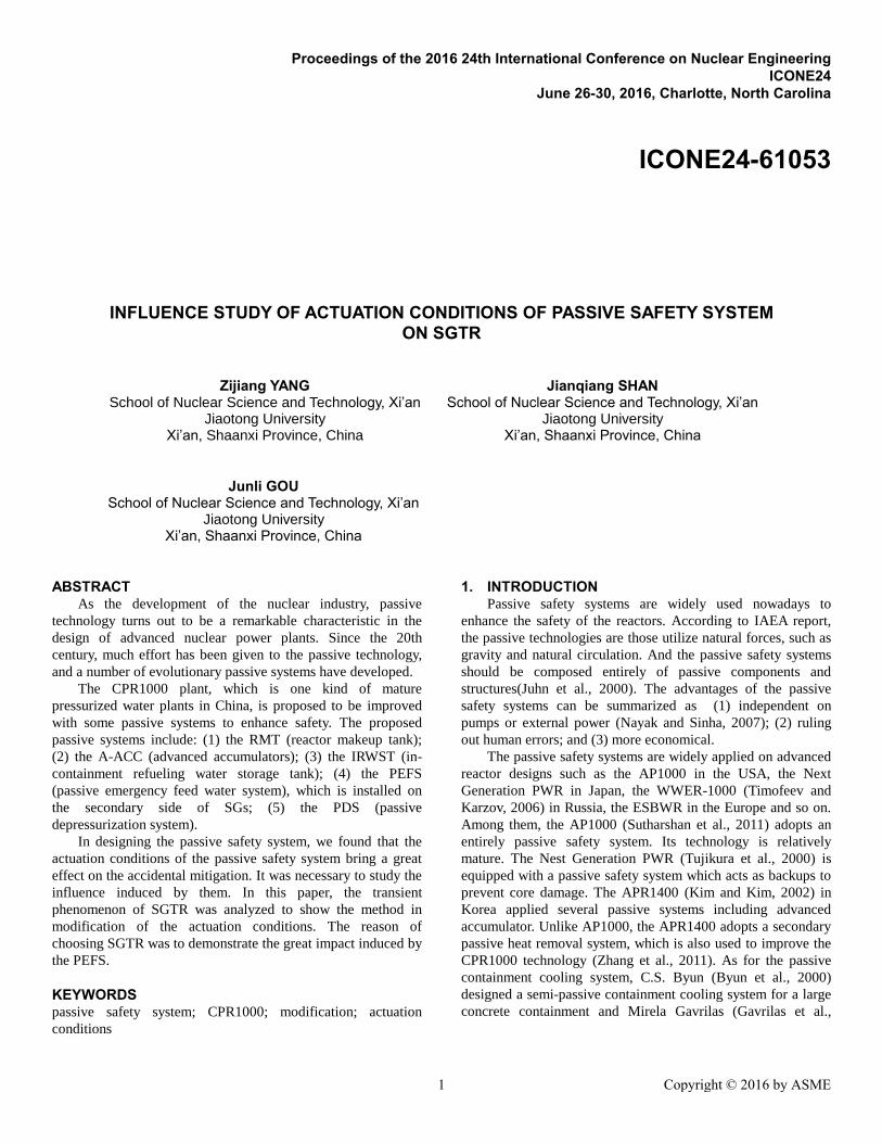
Figure 1 Passive Safety Systems on the Primary Loop
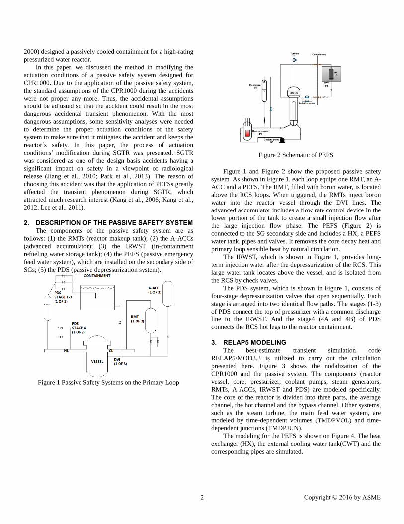
Figure 2 Schematic of PEFS
Figure 1 and Figure 2 show the proposed passive safety
system. As shown in Figure 1, each loop equips one RMT, an A-
ACC and a PEFS. The RMT, filled with boron water, is located
above the RCS loops. When triggered, the RMTs inject boron
water into the reactor vessel through the DVI lines. The
advanced accumulator includes a flow rate control device in the
lower portion of the tank to create a small injection flow after
the large injection flow phase. The PEFS (Figure 2) is
connected to the SG secondary side and includes a HX, a PEFS
water tank, pipes and valves. It removes the core decay heat and
primary loop sensible heat by natural circulation.
The IRWST, which is shown in Figure 1, provides long-
term injection water after the depressurization of the RCS. This
large water tank locates above the vessel, and is isolated from
the RCS by check valves.
The PDS system, which is shown in Figure 1, consists of
four-stage depressurization valves that open sequentially. Each
stage is arranged into two identical flow paths. The stages (1-3)
of PDS connect the top of pressurizer with a common discharge
line to the IRWST. And the stage4 (4A and 4B) of PDS
connects the RCS hot legs to the reactor containment.
3. RELAP5 MODELING The best-estimate transient simulation code
RELAP5/MOD3.3 is utilized to carry out the calculation
presented here. Figure 3 shows the nodalization of the
CPR1000 and the passive system. The components (reactor
vessel, core, pressurizer, coolant pumps, steam generators,
RMTs, A-ACCs, IRWST and PDS) are modeled specifically.
The core of the reactor is divided into three parts, the average
channel, the hot channel and the bypass channel. Other systems,
such as the steam turbine, the main feed water system, are
modeled by time-dependent volumes (TMDPVOL) and time-
dependent junctions (TMDPJUN).
The modeling for the PEFS is shown on Figure 4. The heat
exchanger (HX), the external cooling water tank(CWT) and the
corresponding pipes are simulated.
2 Copyright © 2016 by ASME
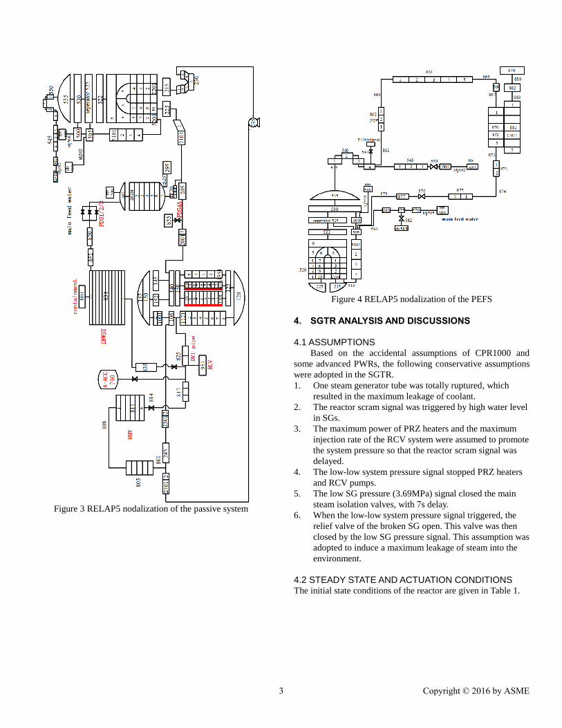
Figure 3 RELAP5 nodalization of the passive system
Figure 4 RELAP5 nodalization of the PEFS
4. SGTR ANALYSIS AND DISCUSSIONS
4.1 ASSUMPTIONS Based on the accidental assumptions of CPR1000 and
some advanced PWRs, the following conservative assumptions
were adopted in the SGTR.
1. One steam generator tube was totally ruptured, which
resulted in the maximum leakage of coolant.
2. The reactor scram signal was triggered by high water level
in SGs.
3. The maximum power of PRZ heaters and the maximum
injection rate of the RCV system were assumed to promote
the system pressure so that the reactor scram signal was
delayed.
4. The low-low system pressure signal stopped PRZ heaters
and RCV pumps.
5. The low SG pressure (3.69MPa) signal closed the main
steam isolation valves, with 7s delay.
6. When the low-low system pressure signal triggered, the
relief valve of the broken SG open. This valve was then
closed by the low SG pressure signal. This assumption was
adopted to induce a maximum leakage of steam into the
environment.
4.2 STEADY STATE AND ACTUATION CONDITIONS The initial state conditions of the reactor are given in Table 1.
3 Copyright © 2016 by ASME
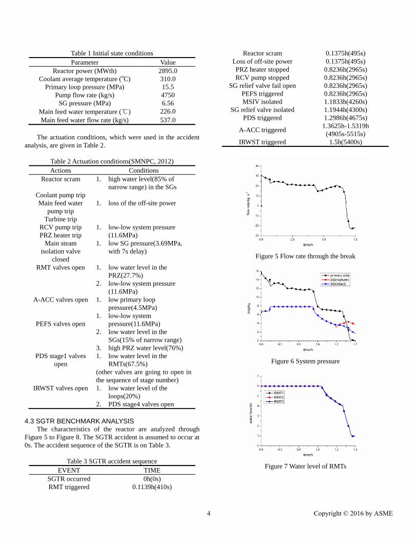
Table 1 Initial state conditions
Parameter Value
Reactor power (MWth) 2895.0
Coolant average temperature (oC) 310.0
Primary loop pressure (MPa) 15.5
Pump flow rate (kg/s) 4750
SG pressure (MPa) 6.56
Main feed water temperature (℃) 226.0
Main feed water flow rate (kg/s) 537.0
The actuation conditions, which were used in the accident
analysis, are given in Table 2.
Table 2 Actuation conditions(SMNPC, 2012)
Actions Conditions
Reactor scram 1. high water level(85% of
narrow range) in the SGs
Coolant pump trip
Main feed water
pump trip
Turbine trip
1. loss of the off-site power
RCV pump trip
PRZ heater trip
1. low-low system pressure
(11.6MPa)
Main steam
isolation valve
closed
1. low SG pressure(3.69MPa,
with 7s delay)
RMT valves open 1. low water level in the
PRZ(27.7%)
2. low-low system pressure
(11.6MPa)
A-ACC valves open 1. low primary loop
pressure(4.5MPa)
PEFS valves open
1. low-low system
pressure(11.6MPa)
2. low water level in the
SGs(15% of narrow range)
3. high PRZ water level(76%)
PDS stage1 valves
open
1. low water level in the
RMTs(67.5%)
(other valves are going to open in
the sequence of stage number)
IRWST valves open 1. low water level of the
loops(20%)
2. PDS stage4 valves open
4.3 SGTR BENCHMARK ANALYSIS The characteristics of the reactor are analyzed through
Figure 5 to Figure 8. The SGTR accident is assumed to occur at
0s. The accident sequence of the SGTR is on Table 3.
Table 3 SGTR accident sequence
EVENT TIME
SGTR occurred 0h(0s)
RMT triggered 0.1139h(410s)
Reactor scram 0.1375h(495s)
Loss of off-site power 0.1375h(495s)
PRZ heater stopped 0.8236h(2965s)
RCV pump stopped 0.8236h(2965s)
SG relief valve fail open 0.8236h(2965s)
PEFS triggered 0.8236h(2965s)
MSIV isolated 1.1833h(4260s)
SG relief valve isolated 1.1944h(4300s)
PDS triggered 1.2986h(4675s)
A-ACC triggered 1.3625h-1.5319h
(4905s-5515s)
IRWST triggered 1.5h(5400s)
Figure 5 Flow rate through the break
Figure 6 System pressure
Figure 7 Water level of RMTs
4 Copyright © 2016 by ASME
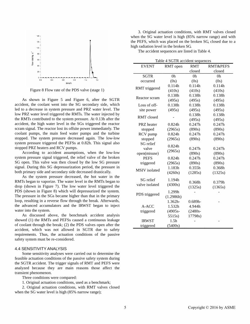
Figure 8 Flow rate of the PDS valve (stage 1)
As shown in Figure 5 and Figure 6, after the SGTR
accident, the coolant went into the SG secondary side, which
led to a decrease in system pressure and PRZ water level. The
low PRZ water level triggered the RMTs. The water injected by
the RMTs contributed to the system pressure. At 0.13h after the
accident, the high water level in the SGs triggered the reactor
scram signal. The reactor lost its offsite power immediately. The
coolant pumps, the main feed water pumps and the turbine
stopped. The system pressure decreased again. The low-low
system pressure triggered the PEFSs at 0.82h. This signal also
stopped PRZ heaters and RCV pumps.
According to accident assumptions, when the low-low
system pressure signal triggered, the relief valve of the broken
SG open. This valve was then closed by the low SG pressure
signal. During this SG depressurization period, the pressure in
both primary side and secondary side decreased drastically.
As the system pressure decreased, the hot water in the
RMTs began to vaporize. The water level in the RMTs began to
drop (shown in Figure 7). The low water level triggered the
PDS (shown in Figure 8) which will depressurized the system.
The pressure in the SGs became higher than that in the primary
loop, resulting in a reverse flow through the break. Afterwards,
the advanced accumulators and the IRWST began to inject
water into the system.
As discussed above, the benchmark accident analysis
showed (1) the RMTs and PEFSs caused a continuous leakage
of coolant through the break; (2) the PDS valves open after the
accident, which was not allowed in SGTR due to safety
requirements. Thus, the actuation conditions of the passive
safety system must be re-considered.
4.4 SENSITIVITY ANALYSIS Some sensitivity analyses were carried out to determine the
feasible actuation conditions of the passive safety system during
the SGTR accident. The trigger signals of RMT and PEFS were
analyzed because they are main reasons those affect the
transient phenomenon.
Three conditions were compared:
1. Original actuation conditions, used as a benchmark;
2. Original actuation conditions, with RMT valves closed
when the SG water level is high (85% narrow range);
3. Original actuation conditions, with RMT valves closed
when the SG water level is high (85% narrow range) and with
the PEFS, which was placed on the broken SG, closed due to a
high radiation level in the broken SG.
The accident sequences are listed in Table 4.
Table 4 SGTR accident sequences
EVENT
RMT open
RMT
closed
RMT&PEFS
closed
SGTR
occurred
0h
(0s)
0h
(0s)
0h
(0s)
RMT triggered 0.114h
(410s)
0.114h
(410s)
0.114h
(410s)
Reactor scram 0.138h
(495s)
0.138h
(495s)
0.138h
(495s)
Loss of off-
site power
0.138h
(495s)
0.138h
(495s)
0.138h
(495s)
RMT closed - 0.138h
(495s)
0.138h
(495s)
PRZ heater
stopped 0.824h
(2965s)
0.247h
(890s)
0.247h
(890s)
RCV pump
stopped
0.824h
(2965s)
0.247h
(890s)
0.247h
(890s)
SG relief
valve
open(misuse)
0.824h
(2965s)
0.247h
(890s)
0.247h
(890s)
PEFS
triggered
0.824h
(2965s)
0.247h
(890s)
0.247h
(890s)
MSIV isolated 1.183h
(4260s)
0.355h
(1285s)
0.368h
(1325s)
SG relief
valve isolated
1.194h
(4300s)
0.368h
(1325s)
0.379h
(1365s)
PDS triggered 1.299h
(1.2986h)
- -
A-ACC
triggered
1.362h-
1.532h
(4905s-
5515s)
0.689h-
4.944h
(2480s-
17798s)
-
IRWST
triggered
1.5h
(5400s)
- -
5 Copyright © 2016 by ASME
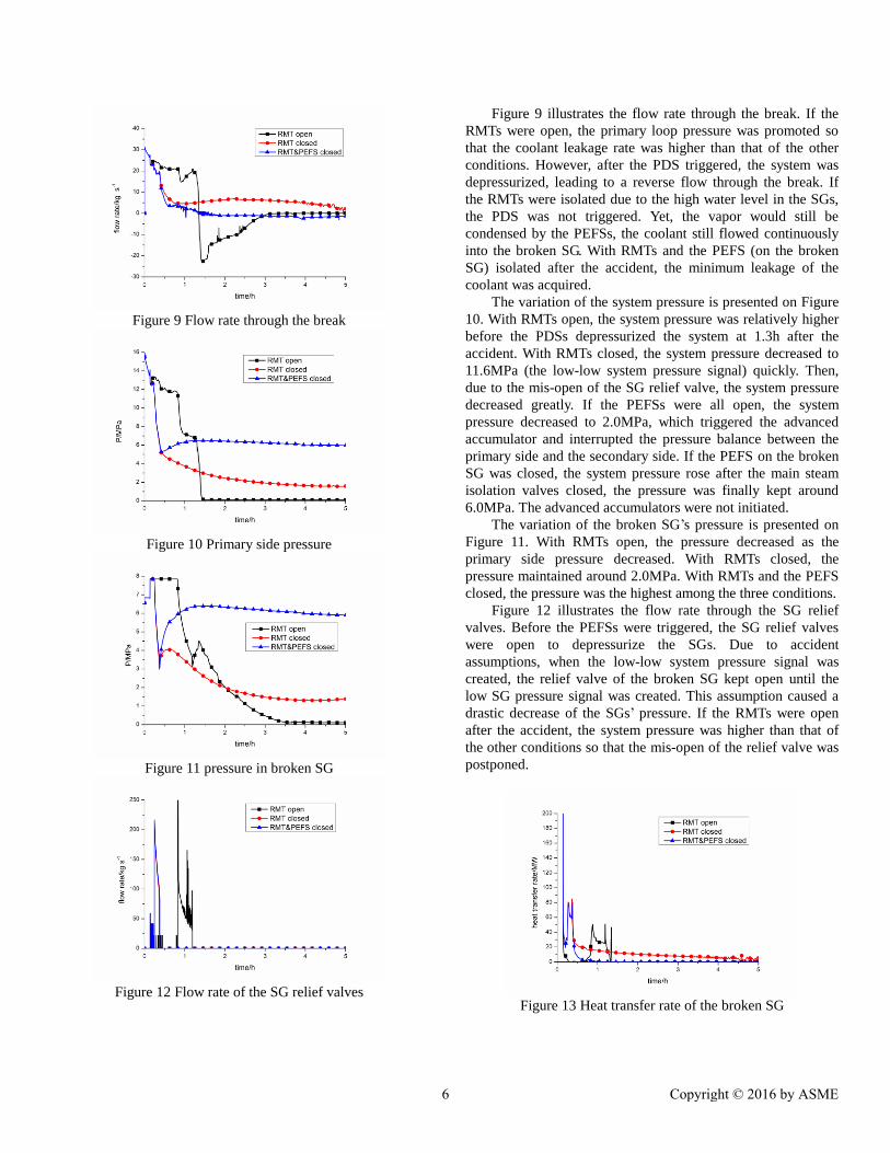
Figure 9 Flow rate through the break
Figure 10 Primary side pressure
Figure 11 pressure in broken SG
Figure 12 Flow rate of the SG relief valves
Figure 9 illustrates the flow rate through the break. If the
RMTs were open, the primary loop pressure was promoted so
that the coolant leakage rate was higher than that of the other
conditions. However, after the PDS triggered, the system was
depressurized, leading to a reverse flow through the break. If
the RMTs were isolated due to the high water level in the SGs,
the PDS was not triggered. Yet, the vapor would still be
condensed by the PEFSs, the coolant still flowed continuously
into the broken SG. With RMTs and the PEFS (on the broken
SG) isolated after the accident, the minimum leakage of the
coolant was acquired.
The variation of the system pressure is presented on Figure
10. With RMTs open, the system pressure was relatively higher
before the PDSs depressurized the system at 1.3h after the
accident. With RMTs closed, the system pressure decreased to
11.6MPa (the low-low system pressure signal) quickly. Then,
due to the mis-open of the SG relief valve, the system pressure
decreased greatly. If the PEFSs were all open, the system
pressure decreased to 2.0MPa, which triggered the advanced
accumulator and interrupted the pressure balance between the
primary side and the secondary side. If the PEFS on the broken
SG was closed, the system pressure rose after the main steam
isolation valves closed, the pressure was finally kept around
6.0MPa. The advanced accumulators were not initiated.
The variation of the broken SG’s pressure is presented on
Figure 11. With RMTs open, the pressure decreased as the
primary side pressure decreased. With RMTs closed, the
pressure maintained around 2.0MPa. With RMTs and the PEFS
closed, the pressure was the highest among the three conditions.
Figure 12 illustrates the flow rate through the SG relief
valves. Before the PEFSs were triggered, the SG relief valves
were open to depressurize the SGs. Due to accident
assumptions, when the low-low system pressure signal was
created, the relief valve of the broken SG kept open until the
low SG pressure signal was created. This assumption caused a
drastic decrease of the SGs’ pressure. If the RMTs were open
after the accident, the system pressure was higher than that of
the other conditions so that the mis-open of the relief valve was
postponed.
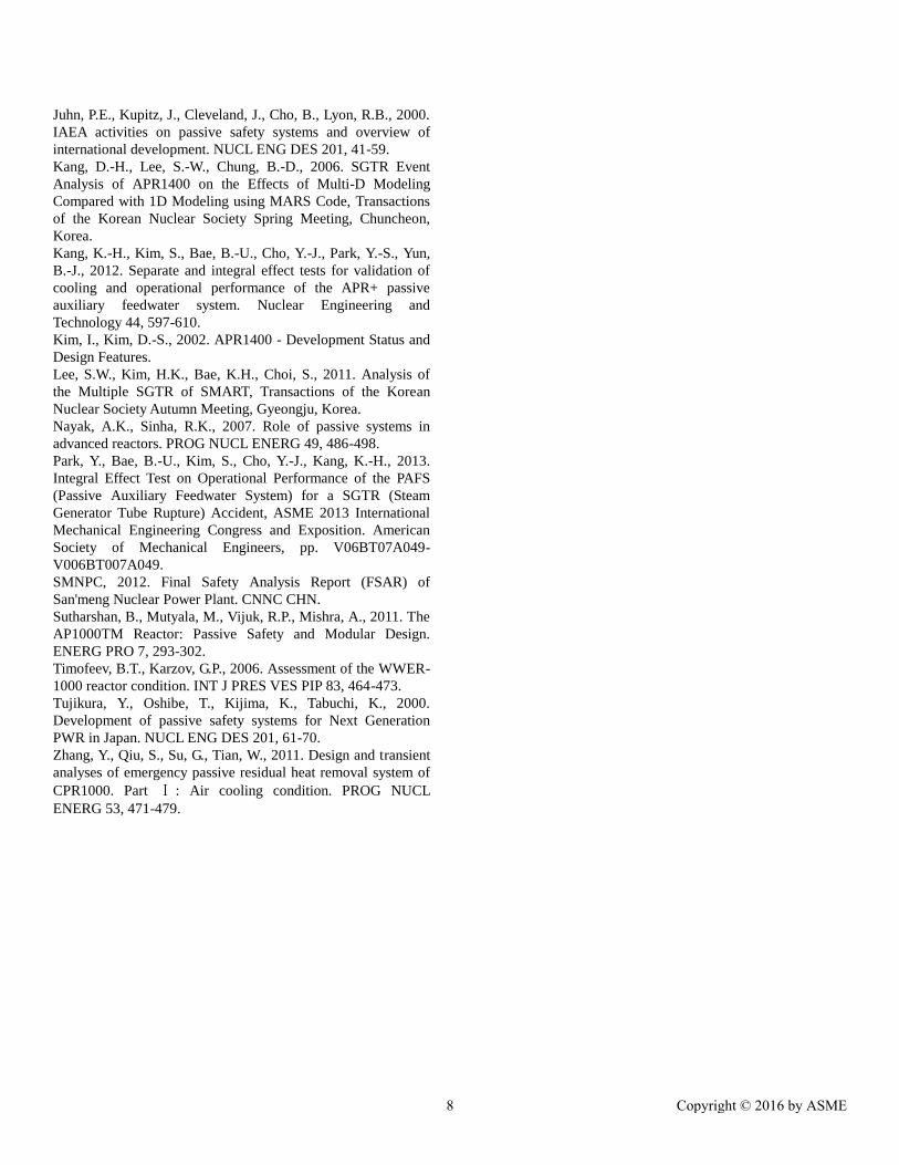
Figure 13 Heat transfer rate of the broken SG
6 Copyright © 2016 by ASME
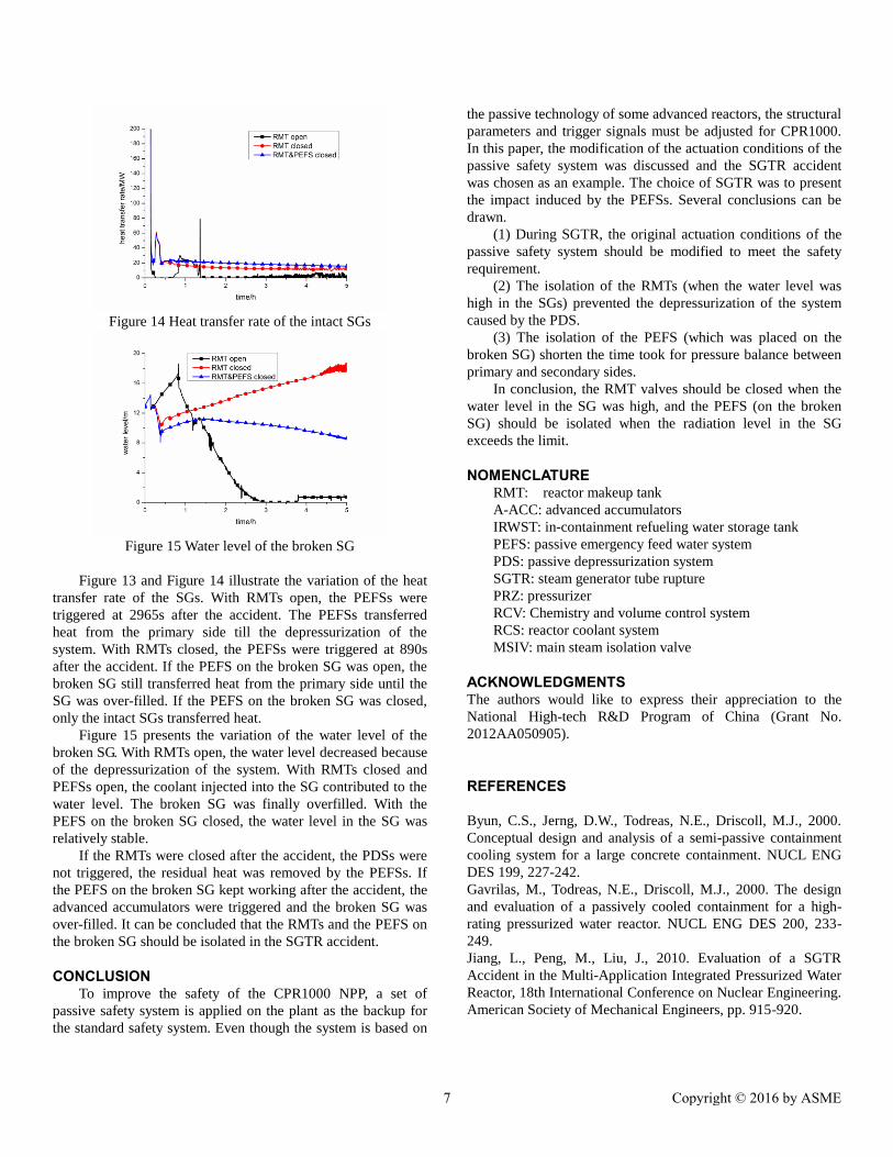
Figure 14 Heat transfer rate of the intact SGs
Figure 15 Water level of the broken SG
Figure 13 and Figure 14 illustrate the variation of the heat
transfer rate of the SGs. With RMTs open, the PEFSs were
triggered at 2965s after the accident. The PEFSs transferred
heat from the primary side till the depressurization of the
system. With RMTs closed, the PEFSs were triggered at 890s
after the accident. If the PEFS on the broken SG was open, the
broken SG still transferred heat from the primary side until the
SG was over-filled. If the PEFS on the broken SG was closed,
only the intact SGs transferred heat.
Figure 15 presents the variation of the water level of the
broken SG. With RMTs open, the water level decreased because
of the depressurization of the system. With RMTs closed and
PEFSs open, the coolant injected into the SG contributed to the
water level. The broken SG was finally overfilled. With the
PEFS on the broken SG closed, the water level in the SG was
relatively stable.
If the RMTs were closed after the accident, the PDSs were
not triggered, the residual heat was removed by the PEFSs. If
the PEFS on the broken SG kept working after the accident, the
advanced accumulators were triggered and the broken SG was
over-filled. It can be concluded that the RMTs and the PEFS on
the broken SG should be isolated in the SGTR accident.
CONCLUSION To improve the safety of the CPR1000 NPP, a set of
passive safety system is applied on the plant as the backup for
the standard safety system. Even though the system is based on
the passive technology of some advanced reactors, the structural
parameters and trigger signals must be adjusted for CPR1000.
In this paper, the modification of the actuation conditions of the
passive safety system was discussed and the SGTR accident
was chosen as an example. The choice of SGTR was to present
the impact induced by the PEFSs. Several conclusions can be
drawn.
(1) During SGTR, the original actuation conditions of the
passive safety system should be modified to meet the safety
requirement.
(2) The isolation of the RMTs (when the water level was
high in the SGs) prevented the depressurization of the system
caused by the PDS.
(3) The isolation of the PEFS (which was placed on the
broken SG) shorten the time took for pressure balance between
primary and secondary sides.
In conclusion, the RMT valves should be closed when the
water level in the SG was high, and the PEFS (on the broken
SG) should be isolated when the radiation level in the SG
exceeds the limit.
NOMENCLATURE RMT: reactor makeup tank
A-ACC: advanced accumulators
IRWST: in-containment refueling water storage tank
PEFS: passive emergency feed water system
PDS: passive depressurization system
SGTR: steam generator tube rupture
PRZ: pressurizer
RCV: Chemistry and volume control system
RCS: reactor coolant system
MSIV: main steam isolation valve
ACKNOWLEDGMENTS The authors would like to express their appreciation to the
National High-tech R&D Program of China (Grant No.
2012AA050905).
REFERENCES
Byun, C.S., Jerng, D.W., Todreas, N.E., Driscoll, M.J., 2000.
Conceptual design and analysis of a semi-passive containment
cooling system for a large concrete containment. NUCL ENG
DES 199, 227-242.
Gavrilas, M., Todreas, N.E., Driscoll, M.J., 2000. The design
and evaluation of a passively cooled containment for a high-
rating pressurized water reactor. NUCL ENG DES 200, 233-
249.
Jiang, L., Peng, M., Liu, J., 2010. Evaluation of a SGTR
Accident in the Multi-Application Integrated Pressurized Water
Reactor, 18th International Conference on Nuclear Engineering.
American Society of Mechanical Engineers, pp. 915-920.
7 Copyright © 2016 by ASME
Juhn, P.E., Kupitz, J., Cleveland, J., Cho, B., Lyon, R.B., 2000.
IAEA activities on passive safety systems and overview of
international development. NUCL ENG DES 201, 41-59.
Kang, D.-H., Lee, S.-W., Chung, B.-D., 2006. SGTR Event
Analysis of APR1400 on the Effects of Multi-D Modeling
Compared with 1D Modeling using MARS Code, Transactions
of the Korean Nuclear Society Spring Meeting, Chuncheon,
Korea.
Kang, K.-H., Kim, S., Bae, B.-U., Cho, Y.-J., Park, Y.-S., Yun,
B.-J., 2012. Separate and integral effect tests for validation of
cooling and operational performance of the APR+ passive
auxiliary feedwater system. Nuclear Engineering and
Technology 44, 597-610.
Kim, I., Kim, D.-S., 2002. APR1400 - Development Status and
Design Features.
Lee, S.W., Kim, H.K., Bae, K.H., Choi, S., 2011. Analysis of
the Multiple SGTR of SMART, Transactions of the Korean
Nuclear Society Autumn Meeting, Gyeongju, Korea.
Nayak, A.K., Sinha, R.K., 2007. Role of passive systems in
advanced reactors. PROG NUCL ENERG 49, 486-498.
Park, Y., Bae, B.-U., Kim, S., Cho, Y.-J., Kang, K.-H., 2013.
Integral Effect Test on Operational Performance of the PAFS
(Passive Auxiliary Feedwater System) for a SGTR (Steam
Generator Tube Rupture) Accident, ASME 2013 International
Mechanical Engineering Congress and Exposition. American
Society of Mechanical Engineers, pp. V06BT07A049-
V006BT007A049.
SMNPC, 2012. Final Safety Analysis Report (FSAR) of
San'meng Nuclear Power Plant. CNNC CHN.
Sutharshan, B., Mutyala, M., Vijuk, R.P., Mishra, A., 2011. The
AP1000TM Reactor: Passive Safety and Modular Design.
ENERG PRO 7, 293-302.
Timofeev, B.T., Karzov, G.P., 2006. Assessment of the WWER-
1000 reactor condition. INT J PRES VES PIP 83, 464-473.
Tujikura, Y., Oshibe, T., Kijima, K., Tabuchi, K., 2000.
Development of passive safety systems for Next Generation
PWR in Japan. NUCL ENG DES 201, 61-70.
Zhang, Y., Qiu, S., Su, G., Tian, W., 2011. Design and transient
analyses of emergency passive residual heat removal system of
CPR1000. Part Ⅰ : Air cooling condition. PROG NUCL
ENERG 53, 471-479.
8 Copyright © 2016 by ASME