Embed Size (px)
Citation preview
INFO 620 Lecture #5 1
Information Systems Analysis and Design
Sequence and Collaboration Diagrams
INFO 620
Glenn Booker
INFO 620 Lecture #5 2
Interaction Diagrams
• Sequence diagrams and collaboration diagrams are both interaction diagrams; they show the interaction among actors, the system, and now, parts of the system
• The RUP’s Design Model consists of the interaction diagrams and the design class diagrams (notice we’re now doing design!)
INFO 620 Lecture #5 3
Dynamic Modeling
• Even more generally, the following are all dynamic models – they show how things move into, out of, and within of the system– Sequence diagram– Collaboration diagram– State (or Statechart) diagram– Activity diagram
• We’ll discuss the latter two things later on
INFO 620 Lecture #5 4
So in Summary
• The sequence and collaboration diagrams therefore have the following shared traits; they are both:– Interaction diagrams– Part of the Design Model of the RUP– Dynamic models of the system
INFO 620 Lecture #5 5
System Sequence Diagram (SSD)
• The SSD focuses on one use case per diagram; and generally one scenario within that use case (the main success scenario)
• The system has been reduced to one box; a class generally called “:System”
• UML only defines a Sequence Diagram; we define the SSD for our purposes
INFO 620 Lecture #5 6
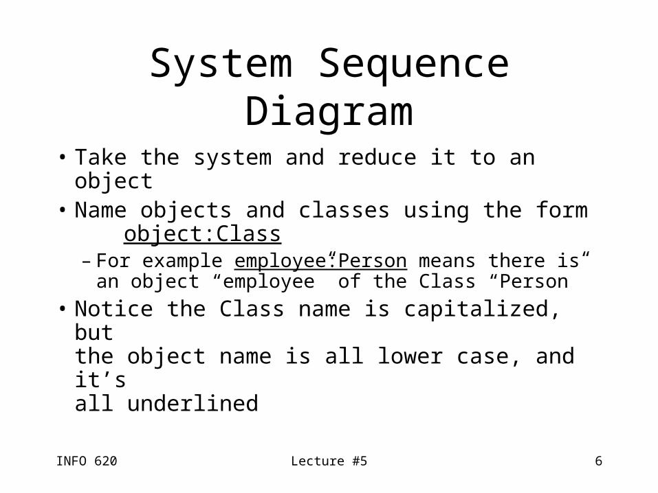
System Sequence Diagram
• Take the system and reduce it to an object• Name objects and classes using the form
object:Class– For example employee:Person means there is
an object “employee” of the Class “Person”
• Notice the Class name is capitalized, but the object name is all lower case, and it’s all underlined
INFO 620 Lecture #5 7
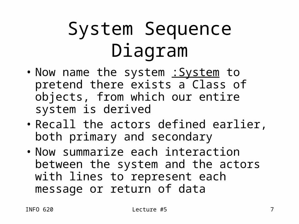
System Sequence Diagram
• Now name the system :System to pretend there exists a Class of objects, from which our entire system is derived
• Recall the actors defined earlier, both primary and secondary
• Now summarize each interaction between the system and the actors with lines to represent each message or return of data
INFO 620 Lecture #5 8
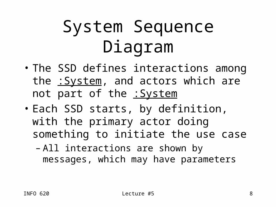
System Sequence Diagram
• The SSD defines interactions among the :System, and actors which are not part of the :System
• Each SSD starts, by definition, with the primary actor doing something to initiate the use case– All interactions are shown by messages, which
may have parameters
INFO 620 Lecture #5 9
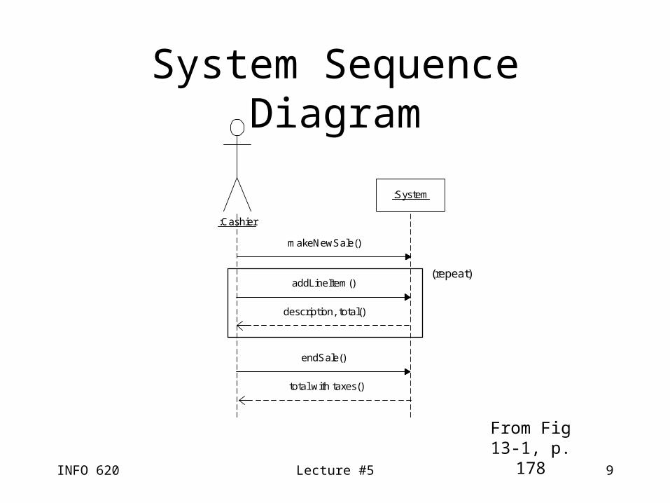
System Sequence Diagram
:System
:Cashier
makeNewSale()
description, total()
addLineItem()
endSale()
total with taxes()
(repeat)
From Fig 13-1, p. 178
INFO 620 Lecture #5 10
System Sequence Diagram
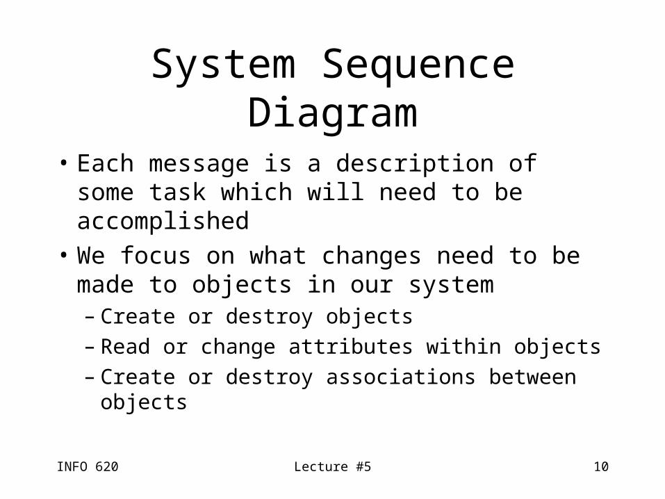
• Each message is a description of some task which will need to be accomplished
• We focus on what changes need to be made to objects in our system– Create or destroy objects– Read or change attributes within objects– Create or destroy associations between objects
INFO 620 Lecture #5 11
System Sequence Diagram
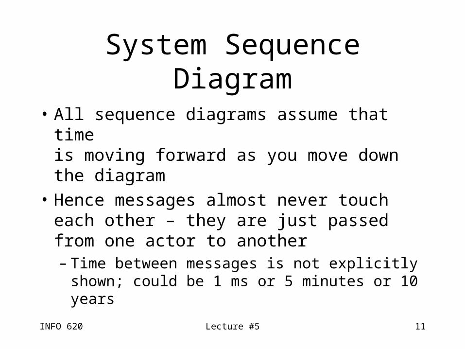
• All sequence diagrams assume that time is moving forward as you move down the diagram
• Hence messages almost never touch each other – they are just passed from one actor to another– Time between messages is not explicitly
shown; could be 1 ms or 5 minutes or 10 years
INFO 620 Lecture #5 12
SSD Actors
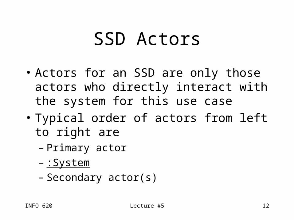
• Actors for an SSD are only those actors who directly interact with the system for this use case
• Typical order of actors from left to right are– Primary actor– :System– Secondary actor(s)
INFO 620 Lecture #5 13
Parameters
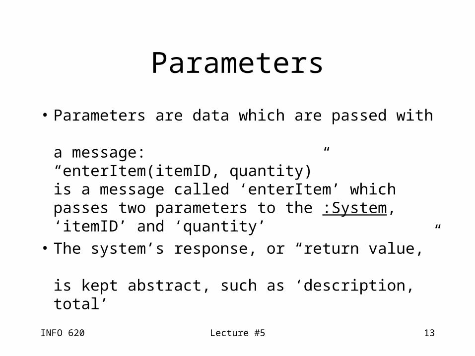
• Parameters are data which are passed with a message:“enterItem(itemID, quantity)” is a message called ‘enterItem’ which passes two parameters to the :System, ‘itemID’ and ‘quantity’
• The system’s response, or “return value,” is kept abstract, such as ‘description, total’
INFO 620 Lecture #5 14
Repeated Events
• A group of events which are repeated are shown in the SSD by a thin solid-lined box around all of the events which repeat
• The group is presumably repeated until the next event after (below) the box takes place
INFO 620 Lecture #5 15
Naming and Defining Events
• Keep names of messages focused on the intent, rather than on how it is input– “enterItem” rather than “scanItem”, so we don’t
limit how the data is entered into the :System
• All messages and parameters named in SSD’s or SQD’s (Sequence Diagrams) should later appear in the Glossary
INFO 620 Lecture #5 16
Adding Use Case Text
• For SSD’s, it is possible (but optional) to show the text of the use case description next to each corresponding line of the SSD (p. 123)
INFO 620 Lecture #5 17
SSD versus SQD
• The System Sequence Diagram (SSD) models the system as one class
• The Sequence Diagram (SQD) shows individual classes within the system which correspond to classes in the Design or Application Class Diagrams
INFO 620 Lecture #5 18
SSD and the Unified Process
• SSD’s are generally not done in the Inception phase
• Most SSD’s are created during Elaboration
INFO 620 Lecture #5 19
Operation Contracts
• Operation contracts are a way of documenting complex SSDs or SQDs
• Each operation, or method, needs to be clearly defined; that definition is a contract which describes its role and responsibilities
• Hence each operation contract describes what each message will need to accomplish
INFO 620 Lecture #5 20
Operation Contracts
• Operation; the name of the operation, and the parameters sent to it
• Cross References; what use cases use this operation
• Preconditions; assumptions about what has occurred before using this operation
• Postconditions; what changed as a result of this operation
INFO 620 Lecture #5 21
Operation Contracts
• Preconditions are expressed in present tense– For the enterItem method, “There is a
sale underway”
• Postconditions are expressed in past tense– “A SalesLineItem instance was created”
• Contracts are used when a method is too complex to represent clearly with a use case
INFO 620 Lecture #5 22
Operation Contracts
• Typically, a method which creates a new object and assigns data to it involves three steps:– Create the instance (make a new object)– Form an association with its parent object
(SaleLineItem is associated with a Sale)– Assign the data to the object
(attribute modification)
INFO 620 Lecture #5 23
Interaction Diagrams
• Sequence diagrams and collaboration diagrams (CD) both show almost the same information, so doing both is redundant (for a given use case)
• How choose which one to do?– SQD focuses on time, shows lifeline of object– CD shows all possible events & context more
clearly, but an individual sequence is less clear
INFO 620 Lecture #5 24
Collaboration Diagrams
• Collaboration diagrams look kind of like flow charts
• Objects are shown by boxes
• Messages between objects are shown by lines connecting the boxes
• Lines are labeled, and have arrows to show in which direction the messages travel
INFO 620 Lecture #5 25
Sample Collaboration Diagram
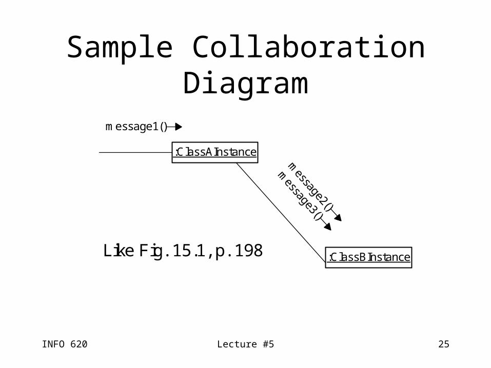
:ClassAInstance
:ClassBInstance
message1()
message2()
message3()
Like Fig. 15.1, p. 198
INFO 620 Lecture #5 26
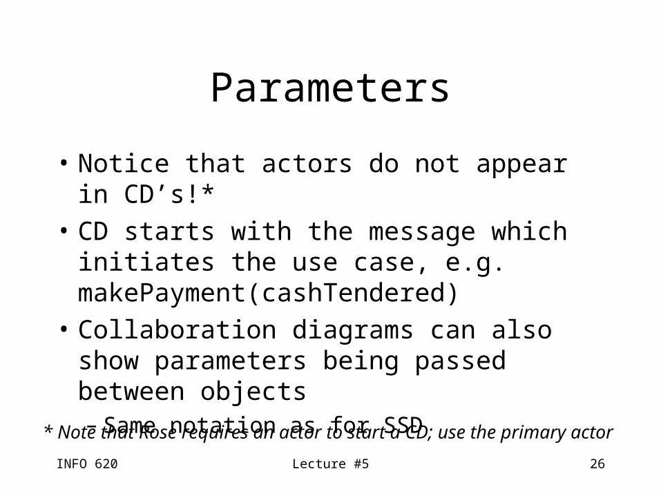
Parameters
• Notice that actors do not appear in CD’s!*
• CD starts with the message which initiates the use case, e.g. makePayment(cashTendered)
• Collaboration diagrams can also show parameters being passed between objects– Same notation as for SSD
* Note that Rose requires an actor to start a CD; use the primary actor
INFO 620 Lecture #5 27
Numbering Messages
• Here is one way a CD differs from an SSD• Messages, after the first one, are numbered
– The first numbered message is ‘1’– Later messages which result from that message
get 0.1 added, e.g. 1.1, 1.2, etc.– The next message from the starting point is ‘2’– And so on…
• See example on page 205, Figure 15.11
INFO 620 Lecture #5 28
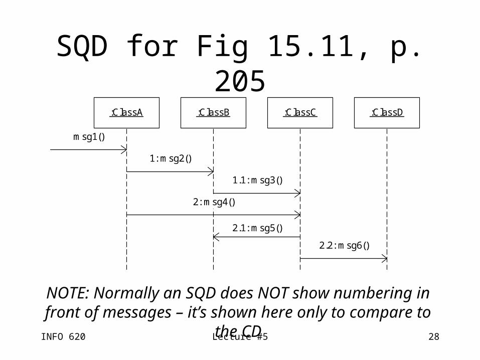
SQD for Fig 15.11, p. 205
:ClassA :ClassB :ClassC :ClassD
msg1()
1: msg2()
1.1: msg3()
2: msg4()
2.1: msg5()
2.2: msg6()
NOTE: Normally an SQD does NOT show numbering in front of messages – it’s shown here only to compare to the CD
INFO 620 Lecture #5 29
Sequence Diagram Notes
• A sequence diagram can have messages passing left or right on the diagram; that’s why a return message uses a dashed line to make its meaning clear
• The left/right position of classes and actors in an SQD or SSD has no inherent meaning– Generally they are shown in the order in which
they are used during the use case
INFO 620 Lecture #5 30
Put It All Together
• Now translate the interaction diagrams to their corresponding class diagram
• This is REALLY IMPORTANT:The target of an arrow in an interaction diagram is the class which implements that message
INFO 620 Lecture #5 31
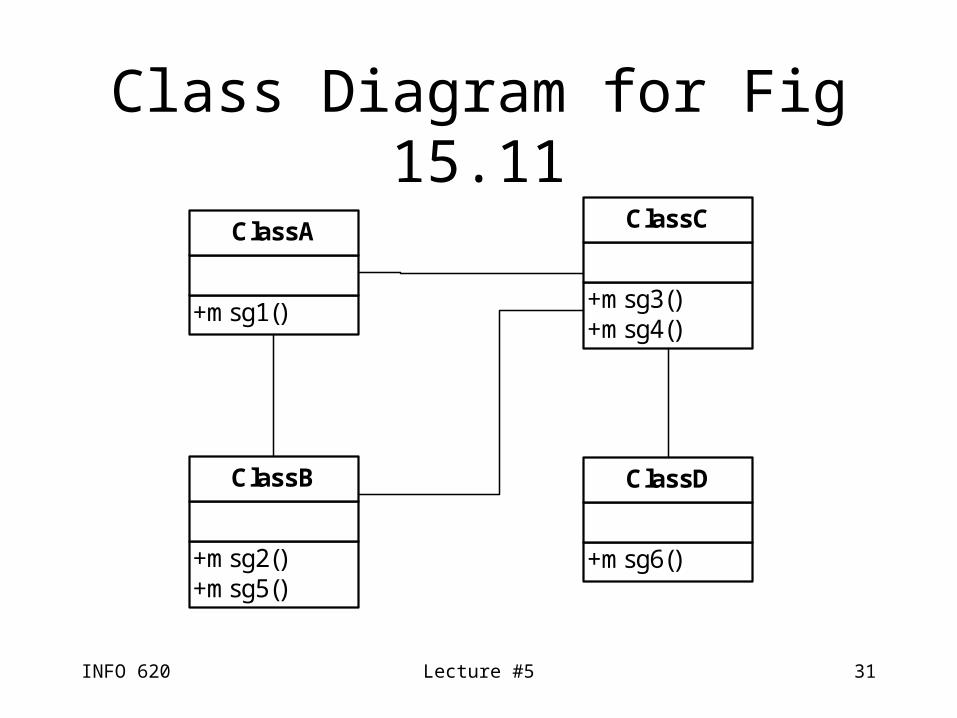
Class Diagram for Fig 15.11
+msg1()
ClassA
+msg2()+msg5()
ClassB
+msg3()+msg4()
ClassC
+msg6()
ClassD
INFO 620 Lecture #5 32
Conditional Messages
• A message may be sent only if some condition is met
• The syntax for this is to put the condition in brackets after the message number, but before the colon, e.g.1 [color = red]: calculate()
• Means that the message ‘calculate’ will be sent only if color = red is a true statement
INFO 620 Lecture #5 33
Mutually Exclusive Messages
• If you have two or more messages, exactly one of which will be used any given time, then the message numbering takes on a letter (a, b, …) after the leading number; from p. 206, Figure 15.13:1a [test1]: msg2()or1b [not test1]: msg4()
INFO 620 Lecture #5 34
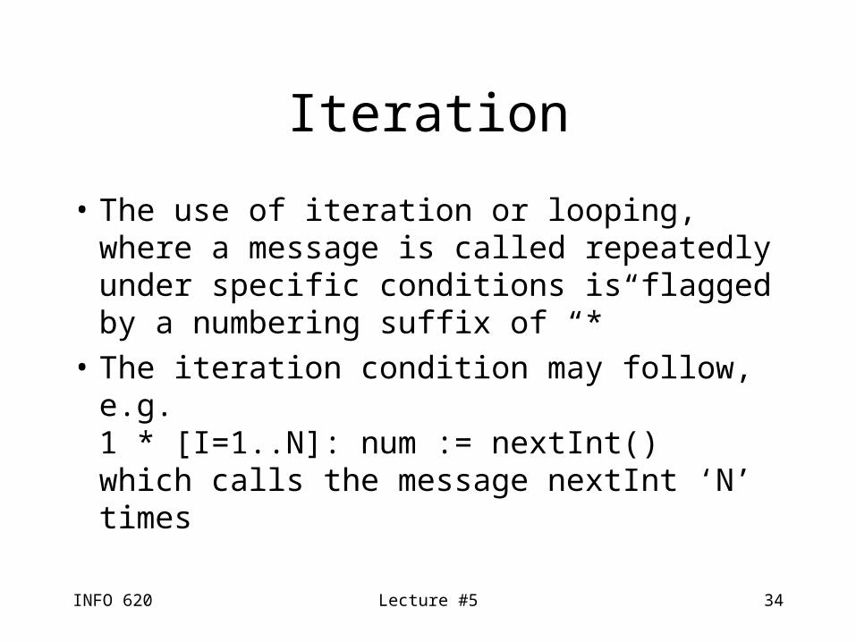
Iteration
• The use of iteration or looping, where a message is called repeatedly under specific conditions is flagged by a numbering suffix of “*”
• The iteration condition may follow, e.g.1 * [I=1..N]: num := nextInt()which calls the message nextInt ‘N’ times
INFO 620 Lecture #5 35
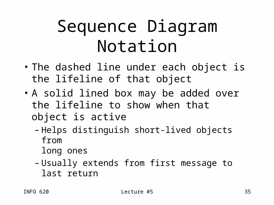
Sequence Diagram Notation
• The dashed line under each object is the lifeline of that object
• A solid lined box may be added over the lifeline to show when that object is active– Helps distinguish short-lived objects from
long ones– Usually extends from first message to
last return
INFO 620 Lecture #5 36
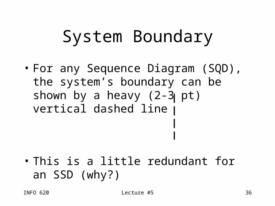
• For any Sequence Diagram (SQD), the system’s boundary can be shown by a heavy (2-3 pt) vertical dashed line
• This is a little redundant for an SSD (why?)
System Boundary
INFO 620 Lecture #5 37
Self-referential Objects
• Objects may send a message to themselves– E.g. a form clearing itself
• This can be shown as a message which turns around 180 degrees (p. 209)
INFO 620 Lecture #5 38
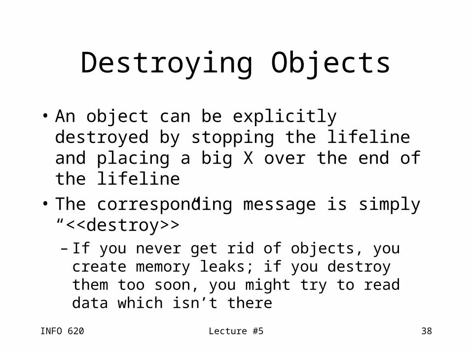
Destroying Objects
• An object can be explicitly destroyed by stopping the lifeline and placing a big X over the end of the lifeline
• The corresponding message is simply “<<destroy>>”– If you never get rid of objects, you create
memory leaks; if you destroy them too soon, you might try to read data which isn’t there
INFO 620 Lecture #5 39
Conditional Messages in SQD
• Conditional messages in a sequence diagram use the same notation as collaboration diagrams, only without the numbering:[color = red] calculate()means “only send the message ‘calculate’ if color equals red” (do nothing otherwise)
INFO 620 Lecture #5 40
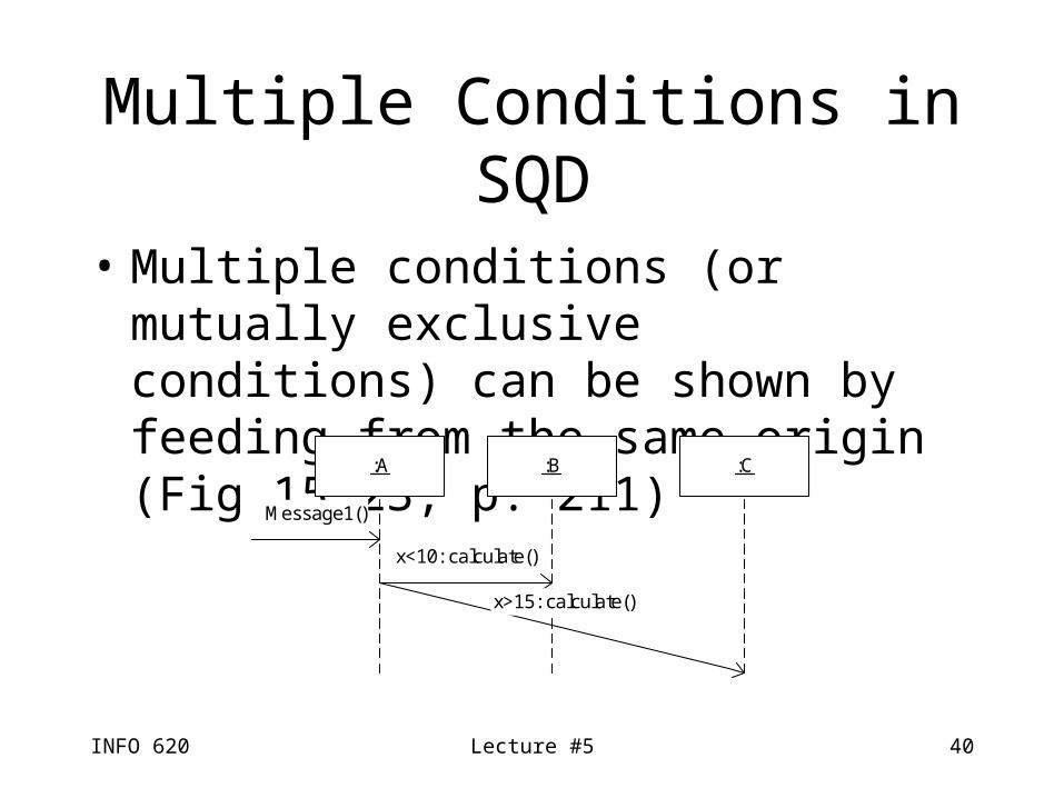
Multiple Conditions in SQD
• Multiple conditions (or mutually exclusive conditions) can be shown by feeding from the same origin (Fig 15.23, p. 211)
:A :B :C
Message1()
x<10: calculate()
x>15: calculate()
INFO 620 Lecture #5 41
Iteration
• Iteration for a sequence diagram uses the same notation as a collaboration diagram* [I=1..N] num := nextInt()
INFO 620 Lecture #5 42
Messages to Classes
• Messages may be sent to classes or static methods, such as libraries
• Denote the name of the class without an underline (e.g. java.util.Collections, instead of :Sale)
• The lack of underline means it’s a class instead of an object