Embed Size (px)
Citation preview
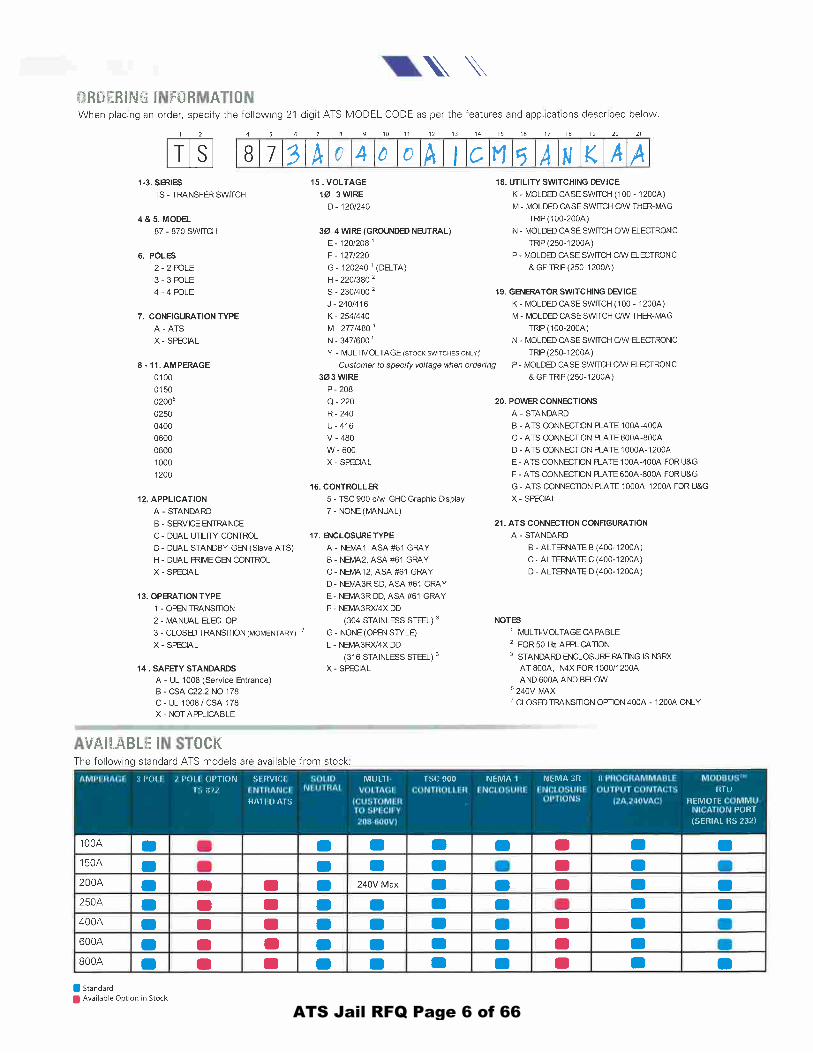
PUBLIC WORKS INFORMAL REQUEST FOR COMPETITIVE QUOTES Project Location: Clatsop County Jail 636 Duane St. Astoria, Oregon Return Quotes no later than: September 14, 2017 prior to 3:00 p.m. Clatsop County is seeking competitive quotes for the following project:
Automatic Transfer Switch Replacement
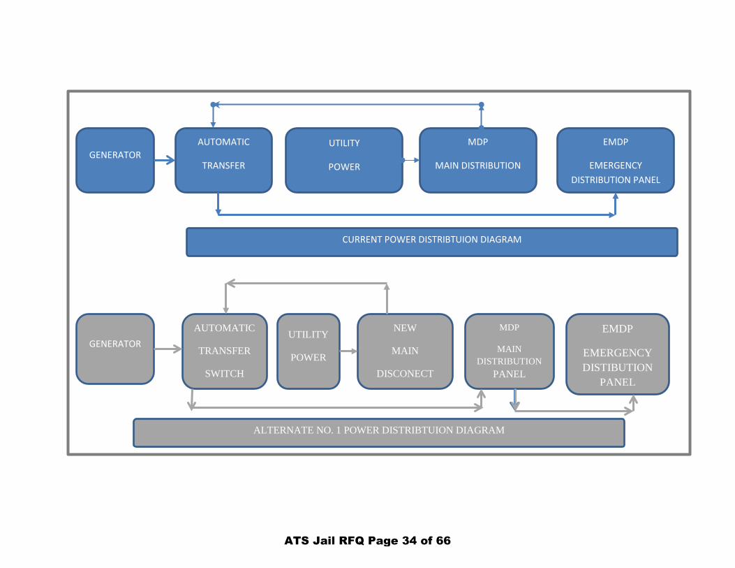
The existing transfer switch is to be replaced. Minimal interruption of power to the jail will be permitted. A non-mandatory pre-bid meeting will be on September, 7th and 11 a.m. Scope of Work: In general the scope of the work is to provide and install a new ATS (Automatic Transfer Switch) in the County Jail. This will include install of the new switch and temporarily rerouting the power that the current switch provides, and implementing a backup system in case of loss of utility power during the work. An alternate in the bid is to install a new Main disconnect and to re-wire to allow the generator to power the entire building. 1. Temporary Wiring to by-pass transfer switch (Maximum power outage 60 minutes.)
a. Temporarily bypass existing transfer switch circuit to allow the continued operation of the jail while the new transfer switch is installed. The goal is to reduce the time the jail has no power to loads that are feed thru the transfer switch.
b. Install temporary wiring from MDP (Main Distribution Panel) to EMDP (Emergency Distribution Panel). Install new 400 AMP breaker and temporary wiring to the EMDP.
c. Upon the final install and testing of the new ATS remove temporary wiring and reconnect ATS circuits to EMDP.
2. Emergency plan
a. In the event of a loss of utility power when the ATS is off line the jail will require the generator to be connected to the EMDP. The generator shall be started and ran until the utility power has been restored for 60 minutes and the utility power is expected to be permanently on line.
ATS Jail RFQ Page 1 of 66

b. Submit a plan that will provide the means and methods to operate the existing generator and provide power to the EMDP in the event of a loss of utility power whiles the ATS install is occurring.
3. Install new transfer switch and remote annunciator.
a. Plan and design install of conductors, conduit and other necessary components. Submit plan to County for approval.
b. Apply for and pay for permits. c. Provide and install transfer switch and remote annunciator. d. Install transfer switch in electrical room. e. Remote annunciator to be located in the vehicle sally port on the 2nd floor of
the jail. f. Install wiring and conductors to make generator system fully functional. g. Perform NFPA 110 Load Bank Testing.
4. Alternate No. 1; Install new 400 Main Disconnect and rewire utility feed to allow the ATS
to supply power to the MDP (Main Distribution Panel). Per the Alternate Power Distribution Diagram and Single Line Diagram.
5. Existing Generator size: 265 kW, 3 phase, 277/480 volt.
6. Provide all accessories necessary and recommended by manufacture for complete installation.
7. Coordinate installation with other trades.
8. An alternate in the bid is to install a new Main disconnect and to re-wire to allow the
generator to power the entire building.
Note the Peak kW Demand for the building as of December, 2016 was 93 kW.
ATS Jail RFQ Page 2 of 66

CONTRACTOR SHALL: Comply with the, State Building Codes and the requirements of local code officials Comply with all OSHA safety requirements Obtain and pay for permit. Assume damage to existing building caused by work on this project and restore any damage Guarantee all work for (1) year from date of completion, unless manufacture provides longer warranty Contractors / Bidders: A non-mandatory pre-bid meeting will be on September, 7th and 11 a.m. The building is available for inspection for other times, please call and make an appointment to inspect prior to bid due date if desired. David Dieffenbach, Capital Improvement Projects Manager 800 Exchange, Suite 222 Astoria, OR 97103 503/338-3695, Fax 503-325-8606 Contact email: [email protected] Bid Proposal Form may be email prior to due date. Clatsop County will be the sole judge in determining award of the contract and reserves the right to reject all proposals. Attached: Bid Proposal Form, Transfer Switch specifications , One Line Diagram, Electrical Specifications, sample contract.
ATS Jail RFQ Page 3 of 66
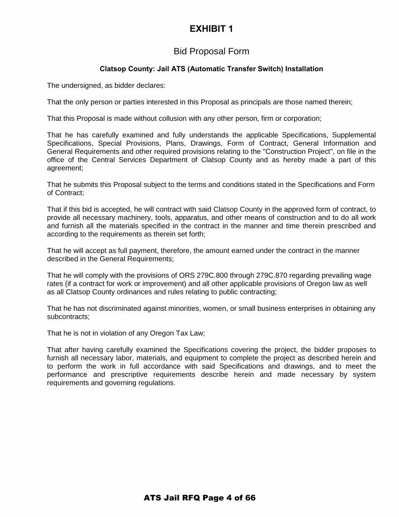
EXHIBIT 1
Bid Proposal Form
Clatsop County: Jail ATS (Automatic Transfer Switch) Installation The undersigned, as bidder declares: That the only person or parties interested in this Proposal as principals are those named therein; That this Proposal is made without collusion with any other person, firm or corporation; That he has carefully examined and fully understands the applicable Specifications, Supplemental Specifications, Special Provisions, Plans, Drawings, Form of Contract, General Information and General Requirements and other required provisions relating to the "Construction Project", on file in the office of the Central Services Department of Clatsop County and as hereby made a part of this agreement; That he submits this Proposal subject to the terms and conditions stated in the Specifications and Form of Contract; That if this bid is accepted, he will contract with said Clatsop County in the approved form of contract, to provide all necessary machinery, tools, apparatus, and other means of construction and to do all work and furnish all the materials specified in the contract in the manner and time therein prescribed and according to the requirements as therein set forth; That he will accept as full payment, therefore, the amount earned under the contract in the manner described in the General Requirements; That he will comply with the provisions of ORS 279C.800 through 279C.870 regarding prevailing wage rates (if a contract for work or improvement) and all other applicable provisions of Oregon law as well as all Clatsop County ordinances and rules relating to public contracting; That he has not discriminated against minorities, women, or small business enterprises in obtaining any subcontracts; That he is not in violation of any Oregon Tax Law; That after having carefully examined the Specifications covering the project, the bidder proposes to furnish all necessary labor, materials, and equipment to complete the project as described herein and to perform the work in full accordance with said Specifications and drawings, and to meet the performance and prescriptive requirements describe herein and made necessary by system requirements and governing regulations.
ATS Jail RFQ Page 4 of 66
Bid Proposal Form BASE BID: Clatsop County: Jail ATS (Automatic Transfer Switch) Installation Bid
General Cost (O&P, Delivery, Bonds, Permits, Supervision, Etc.) $
Temporary wiring to by-pass ATS $
Emergency Plan / Utility Power loss $
Provide and Install New ATS and Remote Annunciator $
Alternate No. 1. Install new Main Disconnect and wiring to power Main Distribution Panel from generator.
$
Misc. $
Total $
______________________________________________________________________
Written amount (total) DOLLARS ($________________________) Date (________________) Performance: Clatsop County Jail ATS The bidder acknowledges that a portion of the work shall be performed outside of the typical Monday through Friday 8:00 AM to 5:00 PM work schedule. In general this applies to the work that creates excess noise and/or requires shut off of the utility power to the building. If this proposal is accepted and the undersigned shall fail to or neglect to contract as aforesaid within ten (10) days from date of receiving from the County, the contract, prepared and ready for execution, the County may at their option, determine that the bidder has abandoned the contract and thereupon forfeiture of the security accompanying this proposal shall operate and the same shall be property of the County. The names of the president, treasurer, and manager of the bidding corporation, or the names and residences of all persons and parties interested in this Bid as partners or principals are as follows: Name Address The names of the surety by which the Performance Bond covering the Contract, if awarded, will be furnished, and the name and address of the surety’s local agent are as follows: Name of Surety Name of Agent Address
ATS Jail RFQ Page 5 of 66
ATS Jail RFQ Page 6 of 66
AUTOMATIC
TRANSFER SWITCHES
TS 870 SERIES
100A-1200A (Molded Case Switch)
2004 CSI FORMAT
SECTION 263623
Specification No. ES019 – ATS Specifications
© 2015 Thomson Power Systems
ES019 Rev 3 15/05/01
ATS Jail RFQ Page 7 of 66
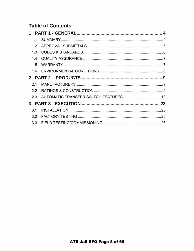
Table of Contents
1 PART 1 - GENERAL .................................................................... 4
1.1 SUMMARY ................................................................................................ 4
1.2 APPROVAL SUBMITTALS ....................................................................... 5
1.3 CODES & STANDARDS ........................................................................... 6
1.4 QUALITY ASSURANCE ........................................................................... 7
1.5 WARRANTY ............................................................................................. 7
1.6 ENVIRONMENTAL CONDITIONS ............................................................ 8
2 PART 2 – PRODUCTS ................................................................ 9
2.1 MANUFACTURERS ................................................................................. 9
2.2 RATINGS & CONSTRUCTION ................................................................. 9
2.3 AUTOMATIC TRANSFER SWITCH FEATURES ................................... 10
3 PART 3 - EXECUTION .............................................................. 23
3.1 INSTALLATION ...................................................................................... 23
3.2 FACTORY TESTING .............................................................................. 25
3.3 FIELD TESTING/COMMISSIONING ...................................................... 26
ATS Jail RFQ Page 8 of 66

THIS PAGE INTENTIONALLY LEFT BLANK
ATS Jail RFQ Page 9 of 66
PROJECT No. Jail ATS Replacement
AUTOMATIC TRANSFER SWITCHES
Page 4 of 27 SECTION 263623
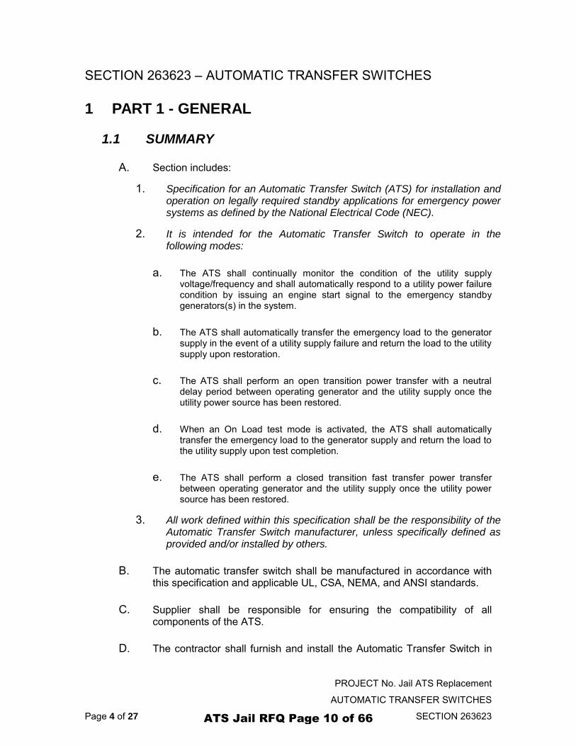
SECTION 263623 – AUTOMATIC TRANSFER SWITCHES
1 PART 1 - GENERAL
1.1 SUMMARY
A. Section includes:
1. Specification for an Automatic Transfer Switch (ATS) for installation and operation on legally required standby applications for emergency power systems as defined by the National Electrical Code (NEC).
2. It is intended for the Automatic Transfer Switch to operate in the following modes:
a. The ATS shall continually monitor the condition of the utility supply voltage/frequency and shall automatically respond to a utility power failure condition by issuing an engine start signal to the emergency standby generators(s) in the system.
b. The ATS shall automatically transfer the emergency load to the generator supply in the event of a utility supply failure and return the load to the utility supply upon restoration.
c. The ATS shall perform an open transition power transfer with a neutral delay period between operating generator and the utility supply once the utility power source has been restored.
d. When an On Load test mode is activated, the ATS shall automatically transfer the emergency load to the generator supply and return the load to the utility supply upon test completion.
e. The ATS shall perform a closed transition fast transfer power transfer between operating generator and the utility supply once the utility power source has been restored.
3. All work defined within this specification shall be the responsibility of the Automatic Transfer Switch manufacturer, unless specifically defined as provided and/or installed by others.
B. The automatic transfer switch shall be manufactured in accordance with this specification and applicable UL, CSA, NEMA, and ANSI standards.
C. Supplier shall be responsible for ensuring the compatibility of all components of the ATS.
D. The contractor shall furnish and install the Automatic Transfer Switch in
ATS Jail RFQ Page 10 of 66
PROJECT No. Jail ATS Replacement
AUTOMATIC TRANSFER SWITCHES
Page 5 of 27 SECTION 263623
accordance with local bylaws, the National Electrical Code (NEC) or Canadian Electrical Code (CEC) specification and contract drawings.
E. Include all components, commissioning and services specified or as required to provide and install a complete and operable automatic transfer switch.
F. The Automatic Transfer Switch package shall include the following main components:
Specification writer’s note: Delete reference to any section which is not applicable to the application.
1. ATS Enclosure
2. Power Switching Mechanism
3. Automatic Transfer Switch Controller:
a. Operator Interface Display
b. Source Voltage & Frequency Sensors
c. ATS control logic c/w Integrated Time Delays, Inputs & Outputs
d. Engine Start Output Contact
e. Load Bus Power Metering
f. Remote Communication ModbusTM
Port
4. Remote annunciator.
1.2 APPROVAL SUBMITTALS
A. Two sets of the following information shall be supplied for ATS approval submittal:
1. ATS Physical Layout (Plan view)
a. ATS Ratings
b. Anchoring Details
c. Cable Entry/Exit Locations
ATS Jail RFQ Page 11 of 66
PROJECT No. Jail ATS Replacement
AUTOMATIC TRANSFER SWITCHES
Page 6 of 27 SECTION 263623
d. Cable Connection Sizes
e. Nameplate Information
2. ATS Schematic Drawings
a. Customer Input/output Electrical Connections
b. Device settings
3. ATS Product Datasheets
B. The following shall be shipped with the equipment:
1. Two sets of As - Built Drawings
2. Hard copy of all Installation Guides.
1.3 CODES & STANDARDS
A. The Automatic Transfer Switch shall be designed, manufactured, tested and listed to the following safety standards:
1. UL 1008 Edition 7 Automatic Transfer Switches For Use in Emergency Systems
2. UL 869A Reference Standard Service Equipment
3. CSA- C22.2 No 178.1-12 Automatic Transfer Switches
B. The ATS Controller shall be designed in accordance with the following performance standards:
1. Immunity Testing;
a. EN 61000-4-2:2009, ESD
b. EN 61000-4-3: 2006 RF Immunity
c. EN 61000-4-4: 2006 EFT
d. EN 61000-4-5: 2006 Surge Voltage
e. EN 61000-4-6: 2009 RF Common Mode
f. EN 61000-4-11: 2004 Voltage Dips and Interruptions
ATS Jail RFQ Page 12 of 66
PROJECT No. Jail ATS Replacement
AUTOMATIC TRANSFER SWITCHES
Page 7 of 27 SECTION 263623
g. EN 61000-4-8: 2010 Power Frequency Magnetic Field Immunity
h. ANSI C62.41.2: 2002 Surge 100kHZ Ring Wave & Combination Wave, Category C
2. Emissions Testing:
a. FCC CFR Part 15, Subpart B, Class A (Radiated & Conducted Emissions)
b. ICES-001 Issue 4, Class A (Radiated & Conducted Emissions)
c. EN 61000-6-4:2007 (Radiated & Conducted Emissions, Harmonics, Flicker)
1.4 QUALITY ASSURANCE
A. The Transfer Switch shall be designed and manufactured in a facility, which is registered to an ISO 9001:2008 quality system. The supplier shall have a minimum of 30 years experience designing and manufacturing automatic transfer switches.
B. Only new materials and components shall be used and of current manufacture.
C. The unit shall be manufactured in accordance with this specification and applicable UL, CSA, and NEMA standards.
1.5 WARRANTY
A. The equipment shall be free of defects in material, workmanship and operation.
B. The Transfer Switch shall be warranted against defective components, workmanship and operational flaws for the period of one year from the date of startup, not to exceed 24 months after shipment.
C. Date of startup shall be when the manufacturer’s representative completes the site startup or when the equipment is put into operation, whichever occurs first.
D. Date of shipment shall be shipment from the supplier or completion of manufacturer in the event the equipment is held at the owner’s request.
ATS Jail RFQ Page 13 of 66
PROJECT No. Jail ATS Replacement
AUTOMATIC TRANSFER SWITCHES
Page 8 of 27 SECTION 263623
E. Provide an additional 36 months parts and labor warranty, for a total of 60 months.
1.6 ENVIRONMENTAL CONDITIONS
A. The Transfer Switch shall be installed with ambient temperatures between +5° to +122° Fahrenheit (-15° to +50° Celsius) relative humidity from 0-95% non-condensing, and altitude not exceeding 6600 ft (2200M).
ATS Jail RFQ Page 14 of 66
PROJECT No. Jail ATS Replacement
AUTOMATIC TRANSFER SWITCHES
Page 9 of 27 SECTION 263623
2 PART 2 – PRODUCTS
2.1 MANUFACTURERS
Specification writer’s note: Insert text to suit the applicable manufactures for this equipment
A. Thomson Power Systems
B. Cummins OTPC 400 AMP.
C.
2.2 RATINGS & CONSTRUCTION
A. Rating of the automatic transfer switch shall be 400 AMP, 480 VAC, 60 Hz, 3 PHASE, _3_WIRE. (Contractor to Verify)
B. The transfer switch shall comprise of _3_switching poles plus a solid neutral. (Contractor to Verify)
C. The automatic transfer switch assembly shall be rated for 100% continuous load without de-rating. The automatic transfer switch shall be suitable for control of motors, electric discharge lamps, tungsten filament lamps, and electric heating equipment where the sum of motor full-load ampere ratings and the ampere ratings of other loads do not exceed the ampere rating of the switch and the tungsten load does not exceed 30 percent of the switch rating.
D. Contractor to determine Available Fault Current and ATS shall have the capacity to handle the current.
E. The automatic transfer switch must be listed or certified to the following safety standards:
UL 1008 Edition 7 Automatic Transfer Switches For Use in Emergency Systems
The complete ATS assembly shall be mounted in a NEMA 1 type enclosure for indoor use.
F. SEISMIC ANCHORING
1. The Transfer Switch shall be designed and constructed to withstand seismic events when correctly anchored to the building structure.
ATS Jail RFQ Page 15 of 66
PROJECT No. Jail ATS Replacement
AUTOMATIC TRANSFER SWITCHES
Page 10 of 27 SECTION 263623
2. The Transfer Switch assembly shall comply with the relevant section of the International Building code standard IBC 2012 and shall be type tested on a shaker table to ACC 156 Standard.
3. The Transfer Switch shall successfully withstand a seismic event with a spectral acceleration of minimum 200%.
4. Specific Transfer Switch anchoring detail drawings shall be furnished by the Transfer Switch supplier to the contractor for compliance of seismic ratings.
5. Transfer Switch supplier shall provide a seismic certificate of compliance upon request.
G. ENCLOSURE FINISH
1. The surface shall be free of nicks and abrasions and all sharp edges broken in preparation for painting the surface. The surface shall then be prepared with iron phosphate treatment and primer. The final coat to be UL approved electrostatically applied powder coat ASA 61 Grey.
2.3 AUTOMATIC TRANSFER SWITCH FEATURES
Specification writer’s note: Delete reference to any section which is not applicable to the application.
A. The transfer switch shall be supplied with multi-voltage capability to allow use on a variety of standard system voltage levels without replacement of components. The transfer switch shall be field configurable to operate on the following nominal system voltages; 208V, 240V, 380V, 480V, 600V.
B. Transfer switch control power shall be obtained from the source being transferred to. The controls shall not require any connection to external power sources for normal automatic operation. Transfer switches requiring control power solely from the engine starting (or other) batteries are not acceptable.
C. A control circuit isolation plug shall be provided to isolate all control circuitry inside the transfer switch to facilitate maintenance procedures. When isolated, there shall be no voltage present on the control circuitry.
D. The transfer switch shall have control plugs for all interconnection to provide superior serviceability. Separate plugs shall be provided for voltage sensing, ATS controller, engine start outputs, programmable I/O and communications. All plugs shall be keyed to prevent incorrect installation.
ATS Jail RFQ Page 16 of 66
PROJECT No. Jail ATS Replacement
AUTOMATIC TRANSFER SWITCHES
Page 11 of 27 SECTION 263623
E. The automatic transfer switch shall include a fully integrated microprocessor-based Transfer Switch Controller which shall provide the following key features:
1. Graphical 7” Color Touch Screen Operator Interface Display
2. Open and/or Closed Transition Transfer Control
3. Utility/Gen Voltage and Frequency Metering
4. Load Bus 3 Phase Power Metering (Optional)
5. ModbusTM RTU Serial Communication
6. ModbusTM TCP/IP Ethernet Communication (Optional)
7. 8 Programmable Relay Output Contacts
8. 16 Programmable Digital Inputs
9. Engine Start Output Contact
F. The transfer switch controller shall include an operator interface graphical color touch screen display which shall be door mounted. The display shall contain the following features:
1. 7.0 inch Diagonal Color Display Screen
2. Capacitive Touchscreen
3. Resolution 800 x 480 (WVGA)
4. Wide Viewing Angle
5. Serial, Ethernet, USB Ports
6. SD Card Memory Card
G. The transfer switch controller display shall provide easy to navigate software menu screens for all ATS system information and control. The following information shall be displayed within the software menuing system:
1. System Time/Date
2. ATS Power Mimic Bus
3. Source Available/ATS Position Indication
4. Utility supply metering – 3 phase voltage and frequency
5. Generator supply metering – 3 phase voltage and frequency
ATS Jail RFQ Page 17 of 66
PROJECT No. Jail ATS Replacement
AUTOMATIC TRANSFER SWITCHES
Page 12 of 27 SECTION 263623
6. ATS Load metering – 3 phase voltage
7. Timer countdown display
8. ATS Control Modes (Auto/Off/Manual/Engine Start)
9. Data Logging of Events
10. Alarm Summary
11. Alarm Logs
12. Event Logs
13. Virtual Synchroscope
14. Calendar-Based Exercise Scheduler
H. The Transfer Switch Controller shall be an Intelligent Electronic Device (IED) which shall have a unique Internet Protocol (IP) Address for programming/configuring and remote communication.
I. The Transfer Switch Controller shall be capable of operating in conjunction with other ATS controllers on a common Ethernet communication network.
J. Password Security: The transfer switch controller software program shall include a three (3) level security password system for access to all programming functions. Specific password levels shall be provided for “read only”, “read/write” and “administrator”. Password security shall allow for users to be named with individual user names and login passwords.
K. All programming/configuring of the transfer switch controller set points including voltage, frequency and time delays shall be software programmable from the front door mounted graphical display screen.
L. Utility/Gen Metering: Digital and Analog (i.e. graphical representative) metering shall be provided by the transfer switch controller for the Utility and Generator supplies. The transfer switch controller shall have an accuracy of +-0.5% (Full Scale) for all voltage and frequency readings. The following standard metering features shall be provided for the utility and generator supplies;
1. Digital and graphical analog display of AC voltages
2. Three phase or single phase voltages (Line to Line & Line to Neutral)
3. Phasor diagram showing graphical phase relationship and voltage magnitude
ATS Jail RFQ Page 18 of 66
PROJECT No. Jail ATS Replacement
AUTOMATIC TRANSFER SWITCHES
Page 13 of 27 SECTION 263623
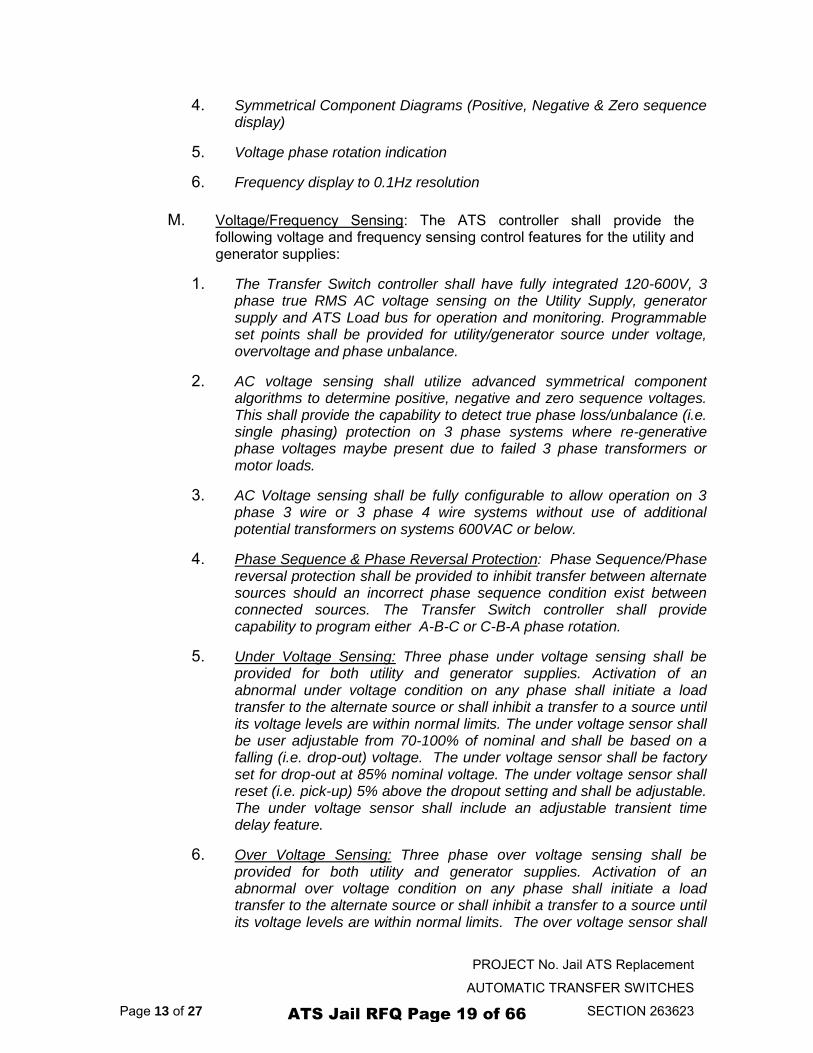
4. Symmetrical Component Diagrams (Positive, Negative & Zero sequence display)
5. Voltage phase rotation indication
6. Frequency display to 0.1Hz resolution
M. Voltage/Frequency Sensing: The ATS controller shall provide the following voltage and frequency sensing control features for the utility and generator supplies:
1. The Transfer Switch controller shall have fully integrated 120-600V, 3 phase true RMS AC voltage sensing on the Utility Supply, generator supply and ATS Load bus for operation and monitoring. Programmable set points shall be provided for utility/generator source under voltage, overvoltage and phase unbalance.
2. AC voltage sensing shall utilize advanced symmetrical component algorithms to determine positive, negative and zero sequence voltages. This shall provide the capability to detect true phase loss/unbalance (i.e. single phasing) protection on 3 phase systems where re-generative phase voltages maybe present due to failed 3 phase transformers or motor loads.
3. AC Voltage sensing shall be fully configurable to allow operation on 3 phase 3 wire or 3 phase 4 wire systems without use of additional potential transformers on systems 600VAC or below.
4. Phase Sequence & Phase Reversal Protection: Phase Sequence/Phase reversal protection shall be provided to inhibit transfer between alternate sources should an incorrect phase sequence condition exist between connected sources. The Transfer Switch controller shall provide capability to program either A-B-C or C-B-A phase rotation.
5. Under Voltage Sensing: Three phase under voltage sensing shall be provided for both utility and generator supplies. Activation of an abnormal under voltage condition on any phase shall initiate a load transfer to the alternate source or shall inhibit a transfer to a source until its voltage levels are within normal limits. The under voltage sensor shall be user adjustable from 70-100% of nominal and shall be based on a falling (i.e. drop-out) voltage. The under voltage sensor shall be factory set for drop-out at 85% nominal voltage. The under voltage sensor shall reset (i.e. pick-up) 5% above the dropout setting and shall be adjustable. The under voltage sensor shall include an adjustable transient time delay feature.
6. Over Voltage Sensing: Three phase over voltage sensing shall be provided for both utility and generator supplies. Activation of an abnormal over voltage condition on any phase shall initiate a load transfer to the alternate source or shall inhibit a transfer to a source until its voltage levels are within normal limits. The over voltage sensor shall
ATS Jail RFQ Page 19 of 66
PROJECT No. Jail ATS Replacement
AUTOMATIC TRANSFER SWITCHES
Page 14 of 27 SECTION 263623
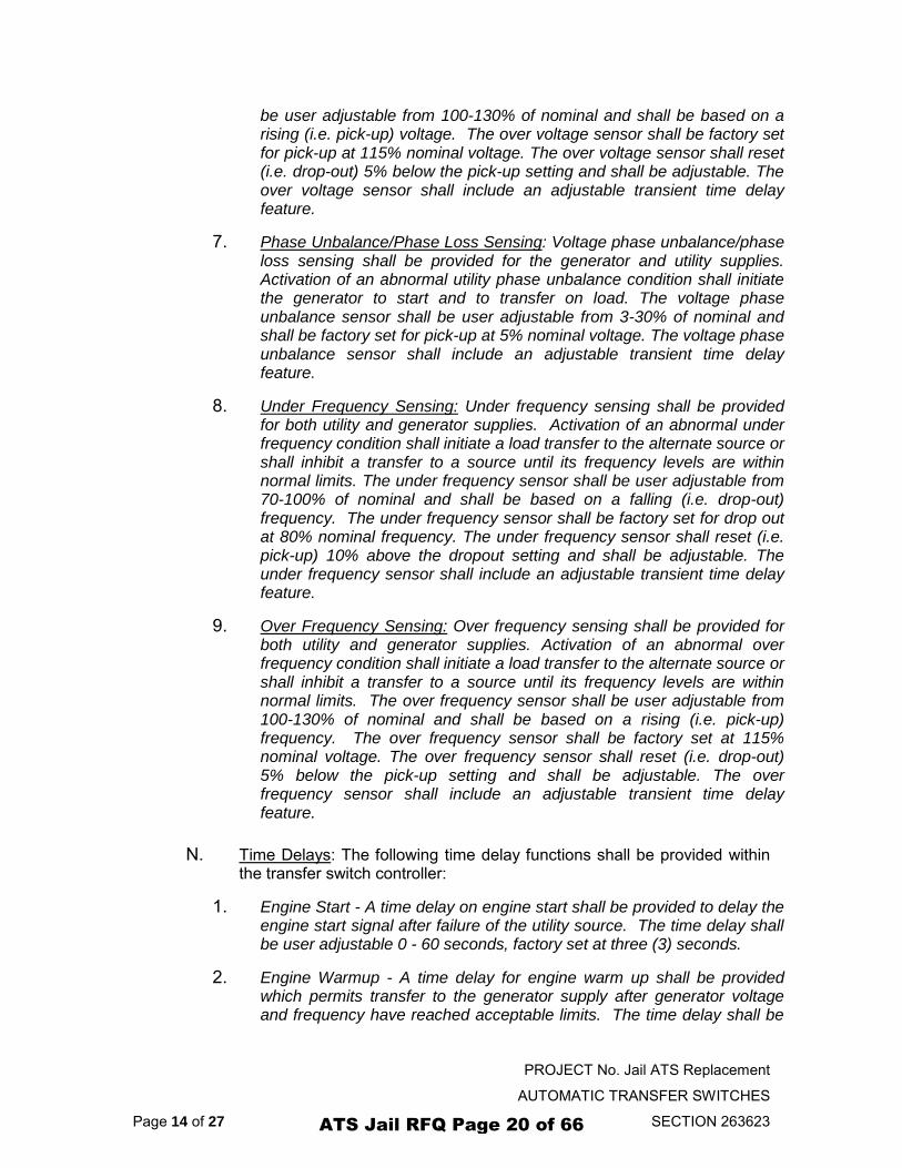
be user adjustable from 100-130% of nominal and shall be based on a rising (i.e. pick-up) voltage. The over voltage sensor shall be factory set for pick-up at 115% nominal voltage. The over voltage sensor shall reset (i.e. drop-out) 5% below the pick-up setting and shall be adjustable. The over voltage sensor shall include an adjustable transient time delay feature.
7. Phase Unbalance/Phase Loss Sensing: Voltage phase unbalance/phase loss sensing shall be provided for the generator and utility supplies. Activation of an abnormal utility phase unbalance condition shall initiate the generator to start and to transfer on load. The voltage phase unbalance sensor shall be user adjustable from 3-30% of nominal and shall be factory set for pick-up at 5% nominal voltage. The voltage phase unbalance sensor shall include an adjustable transient time delay feature.
8. Under Frequency Sensing: Under frequency sensing shall be provided for both utility and generator supplies. Activation of an abnormal under frequency condition shall initiate a load transfer to the alternate source or shall inhibit a transfer to a source until its frequency levels are within normal limits. The under frequency sensor shall be user adjustable from 70-100% of nominal and shall be based on a falling (i.e. drop-out) frequency. The under frequency sensor shall be factory set for drop out at 80% nominal frequency. The under frequency sensor shall reset (i.e. pick-up) 10% above the dropout setting and shall be adjustable. The under frequency sensor shall include an adjustable transient time delay feature.
9. Over Frequency Sensing: Over frequency sensing shall be provided for both utility and generator supplies. Activation of an abnormal over frequency condition shall initiate a load transfer to the alternate source or shall inhibit a transfer to a source until its frequency levels are within normal limits. The over frequency sensor shall be user adjustable from 100-130% of nominal and shall be based on a rising (i.e. pick-up) frequency. The over frequency sensor shall be factory set at 115% nominal voltage. The over frequency sensor shall reset (i.e. drop-out) 5% below the pick-up setting and shall be adjustable. The over frequency sensor shall include an adjustable transient time delay feature.
N. Time Delays: The following time delay functions shall be provided within the transfer switch controller:
1. Engine Start - A time delay on engine start shall be provided to delay the engine start signal after failure of the utility source. The time delay shall be user adjustable 0 - 60 seconds, factory set at three (3) seconds.
2. Engine Warmup - A time delay for engine warm up shall be provided which permits transfer to the generator supply after generator voltage and frequency have reached acceptable limits. The time delay shall be
ATS Jail RFQ Page 20 of 66
PROJECT No. Jail ATS Replacement
AUTOMATIC TRANSFER SWITCHES
Page 15 of 27 SECTION 263623
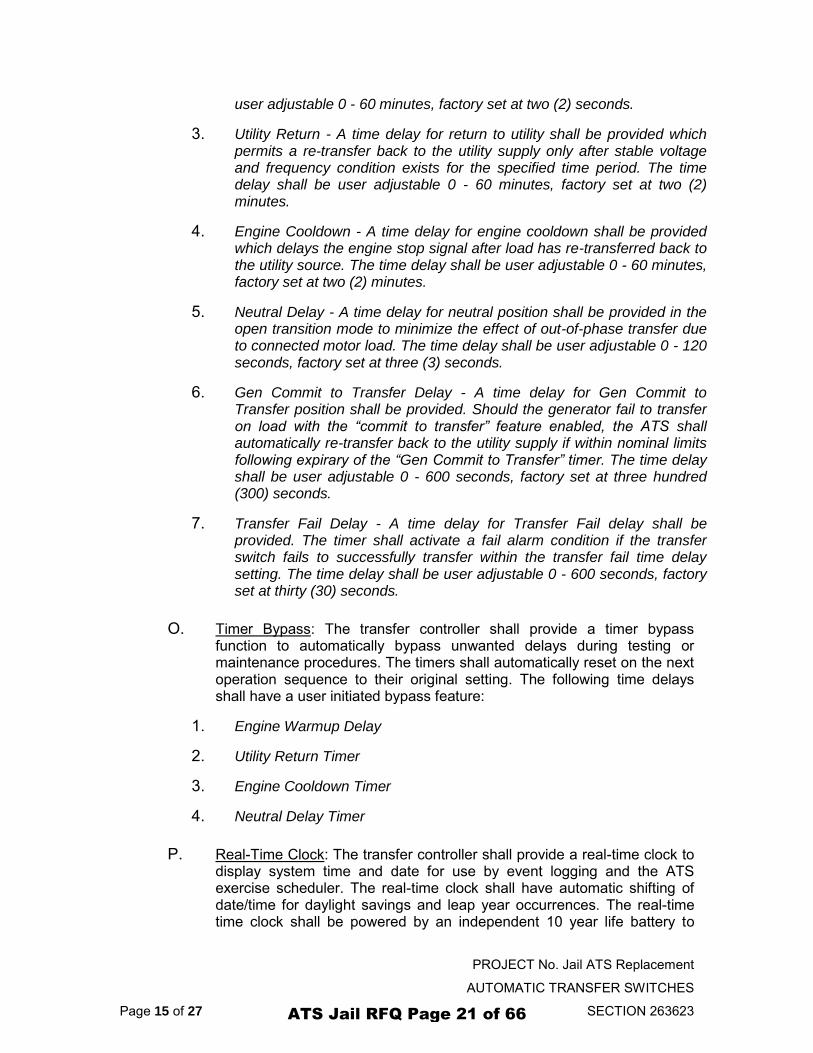
user adjustable 0 - 60 minutes, factory set at two (2) seconds.
3. Utility Return - A time delay for return to utility shall be provided which permits a re-transfer back to the utility supply only after stable voltage and frequency condition exists for the specified time period. The time delay shall be user adjustable 0 - 60 minutes, factory set at two (2) minutes.
4. Engine Cooldown - A time delay for engine cooldown shall be provided which delays the engine stop signal after load has re-transferred back to the utility source. The time delay shall be user adjustable 0 - 60 minutes, factory set at two (2) minutes.
5. Neutral Delay - A time delay for neutral position shall be provided in the open transition mode to minimize the effect of out-of-phase transfer due to connected motor load. The time delay shall be user adjustable 0 - 120 seconds, factory set at three (3) seconds.
6. Gen Commit to Transfer Delay - A time delay for Gen Commit to Transfer position shall be provided. Should the generator fail to transfer on load with the “commit to transfer” feature enabled, the ATS shall automatically re-transfer back to the utility supply if within nominal limits following expirary of the “Gen Commit to Transfer” timer. The time delay shall be user adjustable 0 - 600 seconds, factory set at three hundred (300) seconds.
7. Transfer Fail Delay - A time delay for Transfer Fail delay shall be provided. The timer shall activate a fail alarm condition if the transfer switch fails to successfully transfer within the transfer fail time delay setting. The time delay shall be user adjustable 0 - 600 seconds, factory set at thirty (30) seconds.
O. Timer Bypass: The transfer controller shall provide a timer bypass function to automatically bypass unwanted delays during testing or maintenance procedures. The timers shall automatically reset on the next operation sequence to their original setting. The following time delays shall have a user initiated bypass feature:
1. Engine Warmup Delay
2. Utility Return Timer
3. Engine Cooldown Timer
4. Neutral Delay Timer
P. Real-Time Clock: The transfer controller shall provide a real-time clock to display system time and date for use by event logging and the ATS exercise scheduler. The real-time clock shall have automatic shifting of date/time for daylight savings and leap year occurrences. The real-time time clock shall be powered by an independent 10 year life battery to
ATS Jail RFQ Page 21 of 66
PROJECT No. Jail ATS Replacement
AUTOMATIC TRANSFER SWITCHES
Page 16 of 27 SECTION 263623
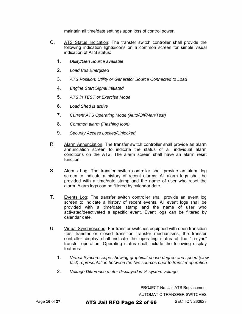
maintain all time/date settings upon loss of control power.
Q. ATS Status Indication: The transfer switch controller shall provide the following indication lights/icons on a common screen for simple visual indication of ATS status:
1. Utility/Gen Source available
2. Load Bus Energized
3. ATS Position: Utility or Generator Source Connected to Load
4. Engine Start Signal Initiated
5. ATS in TEST or Exercise Mode
6. Load Shed is active
7. Current ATS Operating Mode (Auto/Off/Man/Test)
8. Common alarm (Flashing Icon)
9. Security Access Locked/Unlocked
R. Alarm Annunciation: The transfer switch controller shall provide an alarm annunciation screen to indicate the status of all individual alarm conditions on the ATS. The alarm screen shall have an alarm reset function.
S. Alarms Log: The transfer switch controller shall provide an alarm log screen to indicate a history of recent alarms. All alarm logs shall be provided with a time/date stamp and the name of user who reset the alarm. Alarm logs can be filtered by calendar date.
T. Events Log: The transfer switch controller shall provide an event log screen to indicate a history of recent events. All event logs shall be provided with a time/date stamp and the name of user who activated/deactivated a specific event. Event logs can be filtered by calendar date.
U. Virtual Synchroscope: For transfer switches equipped with open transition -fast transfer or closed transition transfer mechanisms, the transfer controller display shall indicate the operating status of the “in-sync” transfer operation. Operating status shall include the following display features:
1. Virtual Synchroscope showing graphical phase degree and speed (slow-fast) representation between the two sources prior to transfer operation.
2. Voltage Difference meter displayed in % system voltage
ATS Jail RFQ Page 22 of 66
PROJECT No. Jail ATS Replacement
AUTOMATIC TRANSFER SWITCHES
Page 17 of 27 SECTION 263623
3. Slip Frequency meter displayed in % of system frequency
4. Generator and Utility Phase A-N voltage
5. Generator and Utility frequency
V. ATS Control Mode: The transfer switch controller shall provide 7 selectable operating modes available from the main operating screen. The following operating modes shall be provided:
1. Auto: ATS shall operate automatically during a utility power failure
2. Off: ATS shall not start engine or transfer load during a utility power failure
3. Manual: ATS can be operated manually to the desired source.
4. On Load Test: ATS shall be selected to operate in On-Load test mode and permit load transfer
5. Off Load Test: ATS shall be selected to operate in Off-Load test mode and shall not permit load transfer
6. Timed Test: ATS shall be selected to operate in a Timed test mode
7. Closed Transition: ATS shall be selected to operate in a Closed Transition Transfer mode
W. Utility Retransfer Operation Selection: The operator interface display shall provide a selection for Utility Re-transfer operation. The utility re-transfer operation shall be user selectable for Automatic, or Manual re-transfer operation. When Manual re-transfer mode is selected, the user can initiate when the re-transfer to utility power shall occur.
X. Test Modes: The transfer switch controller shall provide the following user selectable test modes and features:
1. On Load/Off Load: The operator interface shall provide selection of “OFF-LOAD” testing (i.e. load does not transfer to generator) or “ON-LOAD” testing (i.e. load transfers to generator) modes.
2. Automatic Timed Test Modes: Automatic timed test mode shall be provided to allow for tests to be manually initiated and automatically terminated. Timed test modes shall be user adjustable (0-999 minutes). The load shall automatically re-transfer back to the utility supply should the generator fail on load.
3. Automatic Gen Exerciser: A calendar based automatic exercise time function shall be provided for generator testing. The Exercise scheduler shall be fully programmable for; start/stop date & time, duration of the test and type of test mode (i.e. On-Load or Off-Load). The exercise
ATS Jail RFQ Page 23 of 66
PROJECT No. Jail ATS Replacement
AUTOMATIC TRANSFER SWITCHES
Page 18 of 27 SECTION 263623
timer shall utilize the transfer controller’s internal time clock for referencing all timing functions. The transfer switch shall automatically re-transfer back to the utility supply if the generator set fails during an exercise period.
Y. Scheduler: A calendar based scheduler shall be provided by the transfer switch controller. The scheduler shall operate based on the transfer switch controller real-time clock. The scheduler shall allow users to program over 25 specific event schedules to be added. Each event can be edited individually and it operating status can be monitored. The scheduler shall allow the following programming functionality:
1. Schedule Event Start Date/Time
2. Event Period (Day/Week/Month/Year)
3. Schedule Event Stop Date/Time
4. Event Duration (mins/hours)
5. Event Operation Type (Off-Load Test, On-Load Test)
6. Number of Re-occurring Events (one-time or number of events)
Z. Transfer to Generator Inhibit: The transfer controller shall provide a programmable digital input to inhibit transfer to generator until external signal is removed. Transfer to Generator inhibit shall be automatically bypassed should the utility source fail and the generator source is available within normal limits.
AA. Transfer to Utility Inhibit: The transfer controller shall provide a programmable digital input to inhibit transfer to utility until external signal is removed. Transfer to Utility inhibit shall be automatically bypassed should generator source fail and the utility source is available within normal limits
BB. Generator Source Trip Inhibit: The transfer controller shall provide a programmable digital input to inhibit opening of the generator power switching device until external input signal is removed. Trip inhibit shall be automatically bypassed should generator source fail and utility source is available and/or max parallel time is exceeded.
CC. Transfer Switch Fail Logic: The following transfer switch failure logic and alarming shall be provided during open or closed transition transfer sequences
1. Transfer Fail: Control logic shall be provided for sensing a transfer switch failure in open or closed transition mode. When an alarm condition is activated, the transfer controller shall automatically force a
ATS Jail RFQ Page 24 of 66
PROJECT No. Jail ATS Replacement
AUTOMATIC TRANSFER SWITCHES
Page 19 of 27 SECTION 263623
transfer to the alternate source if available.
2. Power Switching Device Fail: Control logic shall be provided to detect if a power switching device fails to close or open during an open or closed transition operating sequence. Should a power switching device fail to close or open for any reason within a pre-set time period (adjustable), an alarm light and alarm relay contact shall be activated.
3. Gen Failure: Control logic shall be provided for immediate transfer to the utility supply (if within acceptable limits) should the generator set fail during any activated test mode.
DD. Gen Commit to Transfer Logic: Programmable control logic shall be provided to select whether or not the load shall be transferred to the generator (following a utility power failure) if the utility supply is restored immediately before the generator transfers on load. With the feature programmed as NO (DISABLED), the transfer switch shall not commit a transfer to the generator after the engine start delay has expired, but shall return to the utility supply if immediately restored. With the feature programmed as YES (ENABLED), the transfer switch shall commit a transfer to the generator after the engine start delay has expired. This feature shall be automatically cancelled after expirary of the Gen Commit to Transfer timer (5 mins adjustable) should the generator fail to start.
EE. Load Disconnect Contact (LDC): Control logic shall be provided to signal an external load (e.g. elevator) of an impending transfer to and from the generator supply. A single normally open output contact shall be supplied and shall be rated 2A, 120VAC, 28Vdc resistive. The contact shall close prior to a transfer and remain closed until the transfer is completed and the post transfer delay time has expired. A pre-transfer delay function shall be provided, programmable 0 - 30 seconds. A post transfer delay function shall be provided, programmable 0 - 30 seconds.
FF. Engine Start Contacts: Two (2) engine start contacts shall be provided which shall close to initiate starting of the engine. The engine start contact shall be rated 7A, 120/240VAC, 28Vdc resistive.
GG. Load Shed: The transfer controller shall have provisions to provide a load shed output contact via assignment of one of the programmable output contacts. The Load shed output shall be activated whenever the generator transfers on load and shall reset once the utility supply retransfers back on load. If the ATS is equipped with ATS Load bus power metering option, the Load shed feature shall be programmable based on a generator kW load set point.
HH. User Programmable Digital Inputs: Sixteen (16) user programmable digital inputs shall be provided by the transfer controller. The digital inputs shall accept a dry (isolated) logic contact to switch to DC negative
ATS Jail RFQ Page 25 of 66
PROJECT No. Jail ATS Replacement
AUTOMATIC TRANSFER SWITCHES
Page 20 of 27 SECTION 263623
(ground). Each input shall allow mapping to over 30 different control or monitoring functions as available within the transfer controller database. The following inputs shall be mapped as factory defaults:
1. Remote Test - Utility Power Fail Simulate (Close to Test)
2. Remote Alarm Reset (Momentary Close to Reset)
3. Service Disconnect Mode Activated (External Control Switch)
4. Utility Power Switching Device (USD) Tripped
5. Generator Power Switching Device (GSD) Tripped
6. Transfer Control in Manual (External Control Switch)
7. Transfer Control in Closed Transition Mode (External Control Switch)
8. Utility Power Switching Device (USD) Open
9. Generator Power Switching Device (GSD) Open
10. Generator Bypass Switch (GB) Closed
11. Utility Bypass Switch (NB) Closed
12. Load Isolate Switch (LI) Closed
13. Generator Isolate Switch (GI) Closed
14. Utility Isolate Switch (NI) Closed
15. Inhibit Transfer to Utility (Source 1)
16. Inhibit Transfer to Generator (Source 2)
II. User Programmable Output Contacts: Eight (8) user programmable output contacts shall be provided by the transfer controller. The contacts shall be rated 2A, 120/240VAC, 28Vdc resistive, Form C. Each output contact shall be user programmable. The following outputs shall be mapped as factory defaults:
1. Load on Utility (AUX U)
2. Load on Generator (AUX G)
3. Load Disconnect Contact (LDC)
4. Fail to Transfer (FTT)
5. ATS Not in Auto
6. ATS in Auto
ATS Jail RFQ Page 26 of 66
PROJECT No. Jail ATS Replacement
AUTOMATIC TRANSFER SWITCHES
Page 21 of 27 SECTION 263623
7. Utility Power Available (UPA)
8. Generator Power Available (GPA)
JJ. In-Sync Transfer Sensor: For transfer switches equipped to operate in a fast “open” or “closed” transition transfer sequence, the transfer switch controller shall provide an integrated “in-sync” transfer sensor to safely permit in-sync transfers to occur when both sources are available. The in-sync transfer sensor shall provide adjustable voltage and frequency thresholds to only permit transfers when the two sources are safely in phase. The in-sync sensor shall also provide a zero degree closing angle target by utilization of anticipatory closing angle control logic for different levels of slip frequency.
KK. Closed Transition-Fast Transfer: The transfer controller shall provide integrated closed transition control logic to allow the following operating conditions;
1. The transfer controller shall be capable of either open or closed transition operation as selected by operator interface control switch.
2. Closed transition transfer shall only be permitted if both sources are available and the sources are in synchronism (via in-sync sensor permissive signal) prior to interconnection of the two sources.
3. Should an “in-sync” condition not be achieved within a pre-selected time period, an alarm condition shall be activated.
4. If only one source of power is available, and the transfer switch is called to transfer, it shall automatically revert to open transition mode.
5. Under normal operation, both sources of supply shall be inhibited from staying interconnected (in parallel) for longer than 100 milliseconds.
6. Circuitry shall be provided to detect an extended parallel operation time greater than 100 milliseconds. Should the two sources stay interconnected in parallel for longer than 100 milliseconds due to an abnormal condition and independent supervisory circuit shall separate the two sources via alternate tripping signals to ensure the two sources are not interconnected in parallel for longer than a maximum of 500 milliseconds.
LL. Modbus TCP Ethernet Communication: The transfer switch controller shall provide a 100BaseT Ethernet port for customer connection to a remote data monitoring device such as PLC, building automation system or desktop PC. The Ethernet Port shall provide Modbus TCP protocol with data registers defined in the Modbus Communication Manual. The Modbus port shall provide the following main data register information:
1. ATS Position Status
ATS Jail RFQ Page 27 of 66
PROJECT No. Jail ATS Replacement
AUTOMATIC TRANSFER SWITCHES
Page 22 of 27 SECTION 263623
2. ATS Source and Load Status
3. Alarm status
4. Utility/Generator 3 Phase Voltage
5. ATS Load Bus voltage
6. ATS Load Bus Power Metering (kW, kVA, kVAR, PF) when power metering option is provided).
7. Event logging data
MM. Data Logging Memory: The transfer controller shall provide data logging and shall store the data in non-volatile memory on a removable SD memory card. The following events shall be recorded and stored:
1. Total Number of Transfers
2. Total Number of Transfers due to source failure
3. Number of Hours Controller is energized
4. Number of Hours Load is on Utility
5. Number of Hours Load is on Generator
ATS Jail RFQ Page 28 of 66
PROJECT No. Jail ATS Replacement
AUTOMATIC TRANSFER SWITCHES
Page 23 of 27 SECTION 263623
3 PART 3 - EXECUTION
3.1 INSTALLATION
A. Installation Codes/Permits: Suitable permits shall be required by local authorities having jurisdiction prior to installing standby generator sets and automatic transfer switches.
B. Application: The Transfer Switch shall be Listed by Underwriters Laboratories (UL) to Safety Standard UL 1008 for Transfer Switches for Emergency Standby applications. The transfer switch shall be intended for installation and operation on legally required standby applications for emergency power systems as defined by the National Electrical Code (NEC).
C. Installation Location: The transfer switch shall be installed in an environment where the temperature range is within +5° to +122° Fahrenheit (-15° to +50° Celsius) and humidity range not exceeding 5%-95% non-condensing. The transfer switch shall be installed in place of the existing ATS at the jail.
D. Power Cabling: All power cabling entering/exiting the transfer switch enclosure shall be installed in suitably sized conduit per NEC/CEC requirements. Ampacity, type and voltage rating of all power conductors shall also comply with NEC/CEC requirements and local authorities having jurisdiction. To ensure satisfactory installation of this equipment, all power cabling connections shall utilize approved lugs and shall be adequately torqued as specified by the ATS manufacturer. All mechanical and electrical connections shall be checked for tightness prior to placing this equipment in service to ensure proper operation and to validate applicable warranty coverage.
E. Control Wiring: All control wiring for engine start, load shed, alarm and remote test shall be installed in separate conduits from all power cabling and shall be suitably sized conduits per NEC/CEC requirements. All control wiring shall be sized for minimum #18 AWG. Control wiring type and voltage rating shall also comply with NEC/CEC requirements and local authorities having jurisdiction. All field wiring/communication cabling that maybe field installed directly onto any ATS door mounted components shall be suitably routed and protected across the door hinge to prevent possible mechanical damage upon door opening and/or door closing.
F. Generator Set Automatic Starting: The transfer switch shall operate in conjunction with any generator set with remote automatic starting capabilities utilizing a 2 wire, remote start control contact input. A dry
ATS Jail RFQ Page 29 of 66
PROJECT No. Jail ATS Replacement
AUTOMATIC TRANSFER SWITCHES
Page 24 of 27 SECTION 263623
contact shall be provided for remote generator starting control (contact shall close to start generator and shall opens to stop generator).
G. Load Types: The ATS shall be connected to loads for control of motors, electric discharge lamps, tungsten filament lamps, and electric heating equipment where the sum of motor full-load ampere ratings and the ampere ratings of other loads do not exceed the ampere rating of the switch and the tungsten load does not exceed 30 percent of the switch rating.
H. Upstream Overcurrent Protection: Non-Service Entrance Rated transfer switch models do not contain any integral over current protection and shall require upstream over current protection devices for both Utility and Generator sources.
I. Upstream Overcurrent Protection: Service Entrance rated transfer switch models contain integral over current protection for the Utility source as standard. Service Entrance rated transfer switches do not contain any integral over current protection for the generator source and shall require upstream generator source over current protection. The Service Entrance rated transfer switch shall be rated for 80% maximum continuous loading of load types.
J. Withstand/Interrupting Current Ratings: Refer to transfer switch manufactures published electrical ratings for withstand/Interrupting current ratings.
K. Integral Over current Protection: For models of transfer switch with integral over current protection, the over current protection shall be set prior to operation. The equipment shall be supplied from the ATS manufacturer with a long-time current setting of 100% (of the equipment rating) and maximum short-time/instantaneous current and time delay settings.
L. For transfer switches equipped with multi-voltage capability, the installer shall configure the ATS for the correct operating voltage on all transformer taps and shall program the transfer switch controller as required.
M. All changes to the factory default setting changes shall be recorded by the installer on a blank calibration label supplied with the transfer switch.
N. Remote Start Contact Field Wiring: As a minimum, the remote engine start control field wiring shall conform to the local regulatory authority on electrical installations. Field wiring of a remote start contact from a transfer switch to a control panel shall conform to the following additional guidelines to avoid possible controller malfunction and/or damage:
ATS Jail RFQ Page 30 of 66
PROJECT No. Jail ATS Replacement
AUTOMATIC TRANSFER SWITCHES
Page 25 of 27 SECTION 263623
1. Minimum #14 AWG (2.5mm2) wire size shall be used for distances up to 100ft (30m)1).
2. Remote start contact wires shall be run in a separate conduit.
3. Avoid wiring near AC power cables to prevent pick-up of induced voltages.
4. An interposing relay shall be required if field-wiring distance is excessively long (i.e. greater than 100 feet (30m)) and/or if a remote contact has a resistance of greater than 5.0 ohms.
5. The remote start contact shall be voltage free (i.e. dry contact).
O. Dielectric Testing: All high voltage dielectric testing on the transfer switch shall be performed with the transfer switch controller isolated from the test source.
P. Seismic Anchoring: The transfer switch shall be installed per the anchoring details provided for seismic qualification by the ATS manufacturer. The following anchoring guidelines shall be adhered to:
1. Anchoring shall be designed according to IBC 2012 or latest version.
2. If wall anchors are utilized in concrete, applicable concrete type concrete anchors shall be used.
3. If expansion anchors are utilized, they shall be installed according to manufacturer's recommendation.
3.2 FACTORY TESTING
The automatic transfer switch shall be factory tested prior to delivery to the purchaser. The following tests shall be conducted by qualified factory personnel:
A. Visual Inspection: Electrical and Mechanical inspections to verify installed components are of correct ratings; meet the requirements of the project specifications and to ensure regulatory and quality requirements are met.
B. Mechanical Tests: As a minimum, the following mechanical tests shall be performed on the transfer switch:
1. Power Conductor Torque Verification
2. Verification of Mechanical Interlock
3. Manual ATS Mechanism Operation/Adjustment
4. All Mechanical Fasteners/Wire Connections Tight
ATS Jail RFQ Page 31 of 66
PROJECT No. Jail ATS Replacement
AUTOMATIC TRANSFER SWITCHES
Page 26 of 27 SECTION 263623
C. Electrical Tests: As a minimum, the following electrical tests shall be performed on the transfer switch:
1. Adjustment/Setting All Timers & Voltage Sensors
2. Verification of Electrical Interlock
3. Function Test-Normal Operation-3 Complete Cycles
4. Mechanism Adjustment
5. Dielectric Test
D. Final Inspection: As a minimum, the following final inspection tasks shall be performed on the transfer switch:
1. Calibration Label/Equipment labels Installed & Correct
2. All safety/warning labels attached
3. All wiring straight, neatly bundled and adequately protected.
4. All options supplied as specified
5. Enclosure is clean, no paint imperfections
6. Final Documentation is Enclosed (Drawing, O&M Manual)
E. The transfer switch manufacturer shall provide upon request of the project engineer, four (4) copies of certified Factory Test Reports for the transfer switch supplied.
3.3 FIELD TESTING/COMMISSIONING
The automatic transfer switch shall be tested once installed at the project site to confirm proper operation of the system. Schedule and witness testing activities shall be coordinated with the project engineer, site contractor, and owner as required in advance of the testing. Qualified local factory-trained field service representatives shall conduct the following tests:
A. Visual Inspection: Electrical and Mechanical inspection to verify the installation is correct as recommended by the transfer switch manufacturer and as per NEC/CEC requirements.
B. Mechanical Tests: As a minimum, the following mechanical tests shall be performed on the transfer switch:
1. Power Conductor Torque Verification
ATS Jail RFQ Page 32 of 66
PROJECT No. Jail ATS Replacement
AUTOMATIC TRANSFER SWITCHES
Page 27 of 27 SECTION 263623
2. Verification of Mechanical Interlock
3. Manual ATS Mechanism Operation
4. All Mechanical Fasteners/Wire Connections Tight
5. Confirmation of correct transfer switch voltage, current and withstand ratings as is required for the application.
C. Electrical Tests: As a minimum, the following electrical tests shall be performed on the transfer switch:
1. Meggar Testing the Power Cabling to the transfer switch
2. Verification of correct power cabling phasing and phase rotation, prior to energization.
3. Confirmation of settings for all Timers & Voltage Sensors
4. Full Function Test-Normal Operation-3 Complete Cycles of failing the utility supply, and transfer load to/from the generator set.
5. Verification of all Test Modes operate correctly
D. Qualified factory-trained field service personnel shall provide upon request of the project engineer four (4) copies of field test reports noting any deficiencies that require corrective action.
ATS Jail RFQ Page 33 of 66
AUTOMATIC
TRANSFER
UTILITY
POWER
MDP
MAIN DISTRIBUTION
EMDP
EMERGENCY DISTRIBUTION PANEL
CURRENT POWER DISTRIBTUION DIAGRAM
AUTOMATIC
TRANSFER
SWITCH
UTILITY
POWER
NEW
MAIN
DISCONECT
MDP
MAIN DISTRIBUTION
PANEL
EMDP
EMERGENCY DISTIBUTION
PANEL
ALTERNATE NO. 1 POWER DISTRIBTUION DIAGRAM
GENERATOR
GENERATOR
ATS Jail RFQ Page 34 of 66
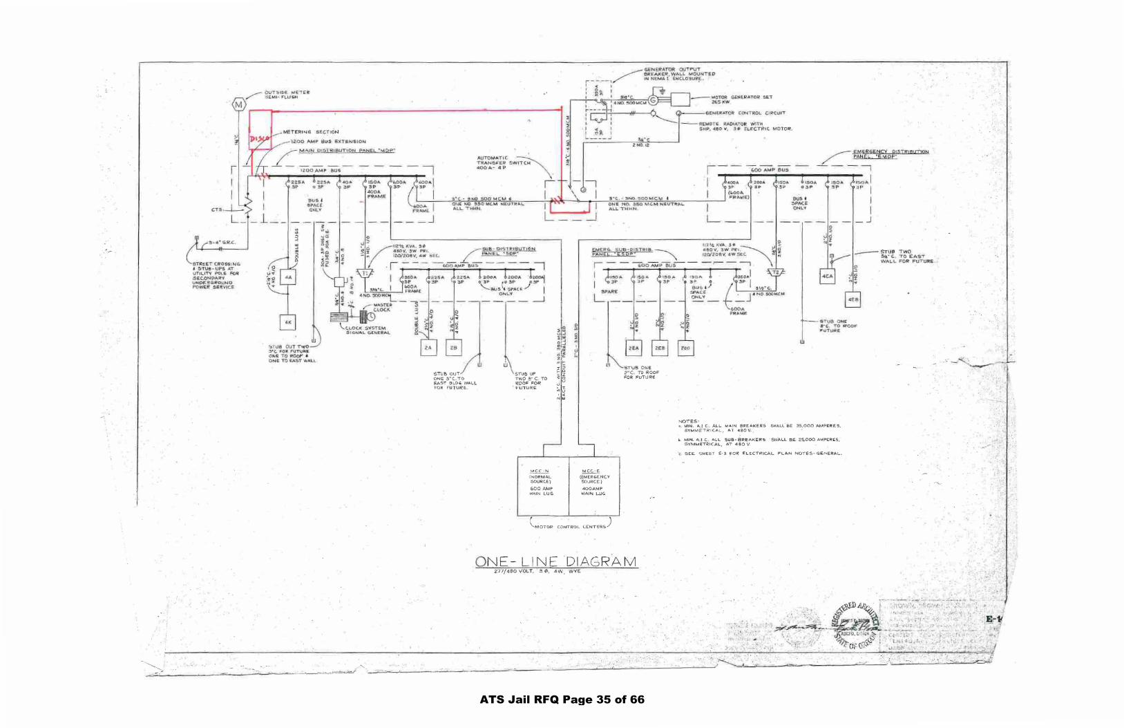
-·.
-- ---.............
e~R.C .
5 TI{S £1"' CRo S:Sl W G I. STU!'- UPS AT VT IUTV P OL.£ FOii .SE.C.Or.JI>AR''1
~~,4~'{,~~
12:00 ,IV.1 P SUS E'IC.fE;N S ION
!JUS j fi PAC.~ OkiLY
:'l 3
w S TUd O~ T T¥(0 3 *C.. FOJt FUT\J~ 91<E Ttl ROOF ~ ONE 10 £A'6T 'W""\.L
l "' ..! ~a: ~ < oo .,., :>e ... lli!
..,., • 0
~!
-·C.::~'-'-~':::·-·_· ----~-...:...~=---~_:'--~--~---_:_-___ ~~ --~~~
AUTOMAT IC ~ TR~NS~"ER SW ITCH coo p., ... 4 P
I I
2 1<0. 12
lfU:CT~I C. "'OTOR:.
~ .!£!~E"REXi l:'lcY Ql:j-TF!' !aUT ION / !!!IS EL. "EM op· - ---,
IO.U A I ~ p I
Q tJ£ friO ~ MC...M N£UT~A.l. A~l.... nlHfl .
ON~ NO, 350 MC. ...., N EV'"'rlltAI.. A LL 1 H t1N. I
[_
I I
.J
Sl1JB OUT ON!;;: 3"(. .10 ~ST 61.01;. WAll FOR FUTURE..
w STUO UP TWO =·c. TO ROOF FOR F"UIURE:
~ ( NORMAL 501,JRC.E)
600 AMP MA.IN LUG
w
MCC - E.
(EMERGENCY SOURCE)
4 0 0AMP ~1AIN UJG
~MOTOR CONTROL (.ENTER-5)
STUB ONE 2"C TO ROOF FOR FUTURE
ONE- LINE 'DIAGRAM 277/480 VOLT, 3 <1>, 4W WVE.
- STUO T WO ~· C. . 'TO EAST WA L..L F OR' F UT IJ.kE ,
NOTES •
5T1.!B ON~ 3 "C, T O Ci!'OO-r • u i 1,.11::i£
MIN. A. [ C ALL MAIN BREAKERS SHALL BE 35,000 AMP,RE.S, SYMMETRICAL, AT 460V.
b MIN. A I C ALL SUB· BREAKI::RS SHALL BE 2.~000 AMPERf.5, SYMMETklCAl, AI 480 V.
c. 5E:E. S HEE..'T' £-3 C::OR' £LECTRJCAL PLAN NOTES-GE.N ERAL .
·> ,: .:
ATS Jail RFQ Page 35 of 66
ATS Jail RFQ Page 36 of 66
BASIC ELECTRICAL REQUIREMENTS CLATSOP COUNTY 26 05 00 - 1 820 EXCHANGE BUILDING
SECTION 26 05 00
BASIC ELECTRICAL REQUIREMENTS PART 1 - GENERAL
A. Work related to Division 16 of the Specifications is described in other Divisions. All Divisions and Sections of these Specifications apply even though not described here.
1.01 WORK INCLUDED
A. This Division of the Specification covers procedures, products, methods, and other electrical aspects of this Contract. Other portions of the Contract Documents may contain electrical requirements also.
B. Drawings:
1. The Drawings are diagrammatic: they do not show every offset, bend, tee, or
elbow which may be required to install work in the space provided and avoid conflicts with other construction.
2. Prior to installing work, take field dimensions, and note conditions available for,
installation. Follow the Drawings as closely as practical to do so, and install additional bends, offsets, and elbows where required by installation conditions. Additional offsets, bends, and other connectors are subject to approval by Project Engineer.
3. Install additional offsets, bends, and other connectors without additional cost to
Owner. 4. The right to make any reasonable changes in outlet location prior to roughing in
is reserved to the Owner’s Representative. 1.02 DEFINITIONS
A. In modification of definitions made elsewhere in this Specification, where the words "furnish", "provide", and "install" appear in this Division, or a manufacturer is indicated with item or product catalog number listed, install and furnish the item complete and operating for the purpose of function intended, unless otherwise noted.
B. All references to power system voltages are RMS per definition in NEC Article 100.
C. “Engineer” means the designated person or firm assigned to be the Owner’s
representative regarding the electrical portions of the Contract. 1.03 SUBSTITUTION REQUESTS
A. Pre-bid Substitution Requests:
1. Follow the requirements of other Contract Documents that describe substitution request requirements. Substitution requests must be received at least 10 days prior to the Bid opening date to be considered. Pre-bid substitution approvals, if granted, will be covered by an Addendum issued to all bidders. So that pre-bid substitution requests may be considered in a timely manner, submission to the Engineer may be made concurrently with the routing required elsewhere in the Contract Documents.
ATS Jail RFQ Page 37 of 66
BASIC ELECTRICAL REQUIREMENTS CLATSOP COUNTY26 05 00 - 2 820 EXCHANGE BUILDING
2. Submit on request form included with the Specifications. If the form is not included, use an industry standard form. Provide complete data substantiating compliance of the proposed substitution with Contract Documents.
1.04 SUBMITTALS
A. Follow requirements of other Contract Documents that describe submittal requirements. Make submittals on the following items:
1. Light fixtures, or fixture components for retrofits.
2. Ballasts (where a specific model is named).
3. Lamps (where a specific model, color, or use condition is named).
4. Wiring devices.
5. Enclosed switch.
6. Over-current protective devices
7. Raceway systems for use in finished areas, which includes “Wiremold” style metallic and non-metallic raceway.
8. Any product included in an equipment schedule.
9. Or as indicated in individual specification sections.
B. Provide complete data substantiating compliance of the submitted item with Contract Documents.
C. Operation and Maintenance Data: Submit the following prior to final acceptance and
Contractor's request for final payment for Division 16 Work in conformance with the Project Closeout requirements of the General Conditions and Division 1.
1. As-built drawings and schedules.
2. Provide three complete sets of Maintenance and Operation Manuals including,
but not limited to, the following:
a. Schematic diagrams, installation wiring diagrams and instructions and Maintenance / Operation Manuals for all signaling, control systems, and equipment.
b. Copies of certificates of Code Authority acceptance, and test data and
other special guarantees, warranties, etc. specified elsewhere and/or indicated on the Drawings.
1.05 DELIVERY, STORAGE, AND HANDLING
A. Acceptance at site:
1. Do not use scratched, marred, or deformed materials. 2. Do not use fixtures, materials, or equipment in wet cartons or boxes, stored in, or
exposed to rain, water, dust, dirt, or snow. 1.06 SEQUENCING AND SCHEDULING
A. Cooperation with Other Crafts: Cooperate with other crafts and/or contracts as may be necessary for the proper execution of the Work in the construction.
ATS Jail RFQ Page 38 of 66
BASIC ELECTRICAL REQUIREMENTS CLATSOP COUNTY 26 05 00 - 3 820 EXCHANGE BUILDING
B. Prior to the installation and connection of the Division 16 Work, verify the requirements indicated in Division 16 with the requirements and characteristics of the other Divisions, the Owner, and/or other contractor's equipment.
C. Obtain wiring or schematic diagrams for confirmation and connections. Bring deviations
to the attention of the Engineer. D. Consult the Drawings of all other trades or crafts to avoid conflicts with cabinets,
counters, equipment, structural members, etc. Conflicts shall be resolved with the Engineer, prior to rough-in.
E. Safety: In accordance with generally accepted construction practices, the Contractor is
solely and completely responsible for conditions of the job site, including the safety of all persons and property during performance of the Work. This requirement applies continuously and is not limited to normal working hours.
1.07 WARRANTY
A. General Warranty: Without additional charge, replace any work or material which develops defects, except from abuse, within one (1) year from final acceptance, unless otherwise noted.
B. Contractor's warranty shall include payment toward normal cost of labor for replacement
of ballasts. 1.08 DESIGN BUILD
A. This Section includes Design-Build work.
1. The intent of Division 16 Specifications and Drawings is to provide a complete and workable facility, with complete systems as required by applicable codes, as indicated, and as specified.
2. Include all work specified in Division 16 and indicated on Drawings, including
appurtenances, connections, fasteners, and accessories required to make a complete working system, whether indicated or not indicated.
3. See Division 1 Section, “Design-Build”.
PART 2 - PRODUCTS 2.01 MANUFACTURERS
A. General: Like items from one manufacturer; i.e., fixture types, switches, receptacles, breakers, panels, etc., unless specifically noted otherwise on Drawings or in Contract Documents.
2.02 MATERIALS
A. Provide electrical materials of the type and quality indicated, or prior approved substitutes, new and listed by the Underwriters’ Laboratories, bearing their label, wherever standards have been established and label service is regularly furnished by them. Brand names and catalog numbers are used to establish standards of performance and quality. The description of materials listed herein governs in the event that catalog numbers do not correspond to the materials described.
ATS Jail RFQ Page 39 of 66
BASIC ELECTRICAL REQUIREMENTS CLATSOP COUNTY 26 05 00 - 4 820 EXCHANGE BUILDING
2.03 ACCESSORIES
A. Special Features and Incidentals:
1. Include special features, finishes, descriptions or requirements indicated in the Contract Documents for particular items or equipment, but not included by or in the item's listed catalog number.
2. Provide and install as part of the Contract work, all incidentals, hangers,
brackets, supports, framing, backing, signal transformers, relays, etc., not specifically mentioned herein or noted on the Drawings, but required to complete the system or systems, in a safe and satisfactory working condition.
2.04 FABRICATION
A. Shop/Factory Finishing: Unless noted otherwise, modify manufacturer's products at the factory to comply with any special requirements noted. The Contractor is responsible for compliance.
PART 3 - EXECUTION 3.01 VERIFICATION
A. Verification of Conditions: The Bidder is expected to visit the site of proposed construction. Verify and inspect the site to determine the conditions that affect this Work. No allowances will be made for conditions that may be determined by cursory inspection.
B. Include in the Bid price all costs for the work and/or the materials required to comply with
the Contract Documents based on existing conditions, or the conditions otherwise described in the Contract Documents where other work is expected to occur prior to the start of electrical construction.
C. Failure to visit the site and verify conditions affecting work of this Division does not relieve the Contractor from the necessity of doing any and all work which is necessary to make all electrical installations and systems complete.
D. Provide electrical equipment and distribution in accordance with NEC 240.83. Verify
available (AIC) fault currents and calculate available fault currents of distribution system.
E. Construction Documents: Electrical Drawings are diagrammatic, with symbols representing electrical equipment, outlets, and wiring.
F. Determine the routing and installation of electrical wiring and equipment with conditions
of construction and acceptance of the Engineer.
G. When deviations from the Drawings are required to make the electrical installation conform to site constraints or to problems associated with other crafts, obtain the Engineer’s approval prior to making any deviations from Drawings.
H. Data given herein and shown on Electrical Drawings is as exact as could be secured, but
absolute accuracy is not guaranteed.
I. Clarification:
1. Prior to submitting a Bid, bring to the attention of the Engineer any ambiguous, conflicting, or unclear instructions. Such items will be clarified by the Engineer in Addendum form.
ATS Jail RFQ Page 40 of 66
BASIC ELECTRICAL REQUIREMENTS CLATSOP COUNTY 26 05 00 - 5 820 EXCHANGE BUILDING
2. In the event that time does not permit clarification prior to Bid opening, the Drawings govern in matters of quantity, the Specifications in matter of quality. In event of conflict on the Drawings or in the Specifications, the greater quantity and the higher quality apply.
3. Should the Contract Documents indicate a condition conflicting with the
Governing Codes and Regulations, refrain from installing that portion of the Work until clarified by the Engineer. Remove and correctly install, as part of the Contract Work, any Work which was installed in violation of the Governing Codes.
3.02 INSTALLATION
A. Codes and Permits:
1. Comply with the latest Rules and Regulations of the Codes of the State and local authorities having jurisdiction. The Contractor is responsible for reviewing the applicable Codes prior to commencing the Work.
2. Furnish all materials and labor required for compliance with these Rules and
Regulations. Items in excess of Code requirements take precedence.
3. Unless otherwise noted in the Contract Documents, obtain and pay for all required permits, plan check charges, and certificates. Deliver Certificates of Acceptance from the Code-Enforcing Authorities to the Engineer.
3.03 FIELD QUALITY CONTROL
A. Tests: Conduct tests of equipment and systems to demonstrate compliance with the requirements specified in Division 16.
B. Provide a journeyman electrician with tools, meters, instruments, and other test
equipment required. Remove and replace trims, covers, fixtures, test materials, systems, methods, and workmanship in the presence of the Engineer for a final review at completion of the Work.
C. In the presence of the Engineer conduct thorough tests of all control systems. Tests
conducted by equipment/system authorized manufacturer's representative are permitted with prior approval.
D. Inspection: Do not close in or cover Work prior to review by the Project Manager.
E. The Contractor is responsible for the cost of uncovering and making repairs where Work
has been closed in or covered prior to review by the Project Manager. This includes trenches and conduits stubbed out from buildings.
3.04 CLEANING
A. Tools and Materials: Keep tools and materials in an orderly manner throughout the construction phase.
B. Upon completion of the Work, remove all excess supplies, materials, tools, etc., furnished
by the Electrical Contractor and subcontractors. C. Dirt, Debris, and Dust: Remove all dirt and debris caused by the execution of the
electrical work from the job site at frequent intervals appropriate to the progress of the Work, or as directed by the Engineer.
ATS Jail RFQ Page 41 of 66
BASIC ELECTRICAL REQUIREMENTS CLATSOP COUNTY 26 05 00 - 6 820 EXCHANGE BUILDING
D. Leave the entire electrical system installed under this Contract clean, dust-free, and in proper working order.
3.05 NOISE CONTROL
A. Contactors, transformers, starters, and similar noise producing devices shall not be placed on walls which are common to occupied spaces, unless specifically called for on the Drawings. Where such devices must be mounted on walls common to occupied spaces, they shall be mounted or isolated in such a manner as to effectively prevent the transmission of their inherent noise to the occupied space.
B. Ballasts, contactors, starters, transformers, and like equipment, which are found to be
noticeably noisier than other similar equipment on the project, will be deemed defective and require replacement.
END OF SECTION
ATS Jail RFQ Page 42 of 66
RACEWAYS CLATSOP COUNTY 26 05 10 - 1 820 EXCHANGE BUILDING
SECTION 26 05 10
RACEWAYS PART 1 - GENERAL 1.01 WORK INCLUDED
A. Raceways. B. Conduit Fittings. C. Sealant. D. Sealing Fire Rated Penetrations. E. Sleeves and Chases.
1.02 CONDUITS
A. Galvanized rigid conduit (GRC) shall be zinc coated mild steel pipe manufactured in accordance with UL-6, ANSI, and Federal Specification W-C-540 standards.
B. Intermediate metallic conduit (IMC) shall comply with UL-1242, Type J and ANSI
Standards. C. Electrical metallic conduit (EMT) shall be steel and comply with UL-797 and ANSI
Standards. D. Non-metallic plastic conduit (PVC) polyvinyl chloride, schedule 40, shall comply with
Federal Specifications W-C-1094 and NEMA TC 6. Carlon, Certainteed, or approved. E. Surface metal raceway shall use snap-in cover and fittings as recommended by the
manufacturer and shall comply with UL 5 standard. Acceptable manufacturers: Wiremold, Walker, or equal.
F. Flexible metal conduit shall be steel and comply with UL 360, ANSI, and Federal
Specifications WW-6-566 standards. Liquid-tight flexible metal conduit shall comply with UL 360 and ANSI Standards.
G. If permitted for use, type MC cable shall be 600v rated, aluminum or steel clad, 90
degrees C rated, with an insulated ground wire. If used for direct bury installation, it shall also be wet rated with type XHHW-cu conductors.
H. If permitted for use, type AC cable shall be 600v rated, aluminum or steel clad, with an
aluminum bond wire. Type AC cable shall not be used for isolated ground circuits. I. Other raceway types are not permitted unless specifically called for on the Plans or
elsewhere in these Specifications, or specifically required to comply with codes. 1.03 FITTINGS
A. GRC and IMC shall be coupled and terminated with threaded fittings. Ends shall be bushed with insulating bushings equal to T&B 1220 or 1230 series.
B. Connectors and couplings for EMT shall be steel concrete tight compression type with
insulated throats on connectors. Connectors shall have a T& B 5030 and 5040 series (or equal) insulating bushing. Indent type connectors shall not be used.
ATS Jail RFQ Page 43 of 66
RACEWAYS CLATSOP COUNTY 26 05 10 - 2 820 EXCHANGE BUILDING
C. Conduits piercing a building waterproof membrane shall be sealed in a manner to effectively prevent leakage through the membrane using industry standard methods approved for the purpose. Where possible, make roof electrical penetrations to HVAC equipment within the footprint of the equipment.
D. Flexible metal conduit shall use screw-in type connectors. Couplings and set-screw type
connectors are not permitted. E. Make seal-offs with fill fiber, compound, large removable cover. All components shall be
of the same manufacturer.
F. Expansion couplings shall be weatherproof with bonding jumper.
G. Locknuts shall be galvanized steel. 1.04 SYSTEM DESCRIPTION
A. General Raceway System Requirements:
1. Concealed Raceway System: Conceal raceway systems throughout unless specifically noted otherwise on Drawings, in the Specifications, or with prior approval of Engineer or Owner.
2. Branch Circuits: Do not change the intent of the branch circuits, or controls, or
combine home runs without Engineer's approval. 3. Unless otherwise indicated, provide raceway systems for lighting, power, Class 1
remote-control and signaling circuits, Class 2 and 3 remote-control signaling, and communication circuits. This includes raceway systems required for Mechanical and HVAC controls. Coordinate requirements with other trades.
4. Raceways for low voltage systems shall be the same as for power systems.
B. Existing Systems:
1. Unless specifically noted otherwise on the Drawings, the Contractor is required to
match or exceed the quality of existing raceways systems when those systems are being modified, extended, or re-located. For the purpose of determining quality, the following list will be used, with the highest quality indicated first and the lowest quality indicated last:
a. Special raceways, including wireways, troughs, explosion proof, cable
trays, and coated rigid conduits.
b. Rigid metallic conduit.
c. Intermediate metallic conduit (IMC).
d. Electrical metallic tubing (EMT), compression fittings.
e. Electrical metallic tubing (EMT), set screw fittings.
f. Type MC cable.
g. Type AC cable.
2. Some existing raceway types may be prohibited for new work. If an existing
raceway system is not covered in the above list, consult the Engineer.
ATS Jail RFQ Page 44 of 66
RACEWAYS CLATSOP COUNTY 6 05 10 - 3 820 EXCHANGE BUILDING
C. New Systems:
1. For all new circuits, or for substantial additions to existing systems, the Contractor may use, where conditions are appropriate, rigid metal conduit, IMC, EMT, MC cable, or AC cable. The use of non-metallic cable is not permitted unless specifically noted as approved. For raceway systems to be used by other trades, use rigid metal conduit, IMC, or EMT unless otherwise noted. Non-metallic raceway (PVC) is restricted to use underground or under slabs unless otherwise noted.
D. All Systems:
1. Flexible metallic conduit shall be used for final connections to lay-in light fixtures,
moveable equipment and vibrating equipment. 2. In all cases, raceways shall be suitable for the environment and shall meet code
requirements. 1.05 SEQUENCING AND SCHEDULING
A. Raceway System: Complete raceway installations before installing conductors or cables. Raceway systems consist of conduit, tubing, duct, or other conveyances intended to route conductors, tubing, or fibers. Fittings include, but are not limited to: connectors, couplings, offsets, elbows, bushings, expansion and deflection fittings, and accessories.
B. Finished Surfaces: Avoid cutting in connection with finished work. Make repairs in a
manner approved by the Engineer. 1.06 SEALANT, THERMAL, AND FIRE-RATED PENETRATIONS
A. Maintain fire ratings at penetrations with sealant or other approved method. Use sealant at penetrations for a thermal break between heated and unheated spaces.
PART 2 - PRODUCTS 2.01 MANUFACTURERS
A. Raceways: Allied Steel, Certainteed, Jones and Laughlin, Carlon, Kraloy, or equal. B. Conduit Fittings: O-Z Gedney, Thomas-Betts, Crouse-Hinds, or equal. C. Fire / Thermal Sealant: Specified Technology Inc., Spec Seal, 3M, or equal.
PART 3 - EXECUTION INSTALLATION
A. Conduit Joints: Assemble conduits continuous and secure to boxes, panels, fixtures, and equipment with fittings to maintain continuity.
B. Conduit Placement: Install continuous conduit and raceways for electrical power and
signal systems wiring. Exposed conduits are permitted in Mechanical Rooms or spaces where walls, ceilings and floors will not be covered with finished materials, or where specifically noted on the Drawings. Where Documents permit exposed conduit, install parallel or at right angles to building lines, tight to finished surfaces, and neatly offset into boxes.
ATS Jail RFQ Page 45 of 66
’ RACEWAYS CLATSOP COUNT 6 05 10 - 4 820 EXCHANGE BUILDING
C. Do not install conduits or other electrical equipment in obvious passages, doorways, scuttles, or crawl spaces where the installation would impede or block the area or the passage's intended use. Do not install conduits on the surface of a building’s exterior, or on top of parapet walls, unless specifically noted on the Drawings.
D. Flexible Conduit: Install a 12-inch minimum slack loop on flexible metallic conduit. E. Conduit Size: Size conduits as indicated on Drawings. Where size is not indicated,
provide conduit in the Code permitted size for THW conductors of quantity shown or required, whichever is greater. Increasing conduit size by one trade size is acceptable without approval. Except where noted, use a minimum size of ½ inch. Install a pull wire or nylon cord in empty raceways provided for other systems. Secure the wire or cord at each end.
F. Use flexible metallic conduit for motors and equipment connections that are subject to
movement or vibration. For exterior locations, moist or humid atmosphere, oil or grease environments, and water spray areas, use PVC coated flexible metallic conduit.
G. Floor, Ceiling, and Wall Penetrations:
1. Provide necessary rigid conduit sleeves, openings, and chases where conduits
or cables are required to pass through floors, ceiling, or walls. 2. Maintain the integrity of fire ratings at penetrations of walls, ceilings, or floors.
END OF SECTION
ATS Jail RFQ Page 46 of 66
WIRES & CABLES CLATSOP COUNTY 6 05 20 - 1 820 EXCHANGE BUILDING
SECTION 26 05 20
WIRES & CABLES 1 GENERAL 1.01 WORK INCLUDED
A. Wires and Cables. B. Connectors. C. Lugs and Pads.
PART 2 - PRODUCTS 2.01 MANUFACTURERS
A. Wires and Cables: Anaconda, General Electric, Hatfield, Okonite, or equal. B. Connectors for stranded conductors: Anderson, Burndy, Ilsco, T&B, or equal. C. Branch Circuit Splices: Ideal, 3M, or equal.
2.02 WIRES AND CABLES
A. General Requirements:
1. Copper conductors, 600 volt insulation for line voltage circuits.
2. Conductors #10 AWG and smaller may be either solid or stranded.
3. Match existing color code, if any. If not, for phases A, B, anc C, use:
a. black, red, and blue on 208v systems
b. black, orange, and blue for 240v delta systems (orange is high leg)
c. brown, orange, yellow for 480v systems
4. Use code approved colors for neutral and ground conductors.
5. Use insulation types THWN, THHN, or XHHW unless noted otherwise.
6. Aluminum conductors are not permitted unless noted. 2.03 CONTROL CABLES
A. Class 2 Wiring: Unless larger conductors are required by the equipment, use 18 gauge, stranded copper, two conductor minimum. Insulation shall meet the requirements of the accessible building void space if required by Code. Use plenum rated cable where required.
2.04 CONNECTORS
A. Lugs: Use indent/compression type with stranded branch circuit or control conductors.
B. Solid Conductor Branch Circuits: Spring connectors, wire nuts, for conductors #18 through #8 AWG.
ATS Jail RFQ Page 47 of 66
CLATSOP COUNTY 6 05 20 - 2 820 EXCHANGE BUILDING
PART 3 - EXECUTION 3.01 INSTALLATION
A. Conductor Installation: Install conductors in raceways having adequate, code size cross-sectional area. Install conductors with care to avoid damage to insulation during installation. Do not apply greater tension on conductors than recommended by manufacturer.
B. Conductor Size and Quantity: Install no conductors smaller than #12 AWG for line
voltage circuits unless otherwise shown. Number of conductors in a conduit run (except ground) may be indicated on Drawings with diagonal hash marks on conduit run.
C. Conductors in Panels and Cabinets: Cable and tree all wires in panels and cabinets for
power and control. Use plastic ties in panels and cabinets. Tie and bundle feeder conductors in wireways of panelboards. Hold conductors away from sharp metal edges.
END OF SECTION
ATS Jail RFQ Page 48 of 66
BOXES CLATSOP COUNTY 6 05 30 - 1 820 EXCHANGE BUILDING
SECTION 26 05 30
BOXES PART 1 - GENERAL 1.01 WORK INCLUDED
A. Outlet Boxes. B. Weatherproof Outlet Boxes. C. Junction and Pull Boxes. D. Conduit Fittings.
1.02 SYSTEM DESCRIPTION
A. Outlet System: Provide electrical boxes and fittings as required for a complete installation. Items shall include but not be limited to outlet boxes, junction boxes, pull boxes, bushings and locknuts.
B. Code Compliance: Comply with governing Codes as applicable to construction and
installation of electrical boxes and fitting. Size boxes according to NEC Article 370, except as noted otherwise.
PART 2 - PRODUCTS 2.01 MANUFACTURERS
A. Outlet Boxes: Bowers, Raco, or equal. B. Weatherproof Outlet Boxes: Bell, Red Dot, or equal. C. Junction and Pull Boxes: Circle AW, Hoffman, or equal. D. Box Extension Adapter: Bell, or equal. E. Conduit Fittings: O-Z Gedney, Thomas and Betts, or equal.
2.02 OUTLET BOXES
A. Luminaire Outlet: Four inch (4 inch) octagonal box, 1-½ inch deep (minimum) with d inch fixture stud if required. Provide raised covers on bracket outlets and on ceiling outlets.
B. Device Outlet: Installation of one or two devices at common location, use a minimum 4
inch square, minimum 1-½ inch deep. Single or two gang flush device raised covers. Raco Series 681 and 686.
C. Construction: Provide galvanized steel interior outlet wiring boxes, of the type, shape,
and size to suit each location and installation; constructed with stamped knockouts in back and sides, and with threaded holes and screws for securing box covers or wiring devices.
D. Accessories: Provide outlet box accessories as required for each installation, including
mounting braces, wallboard hangers, extension rings, fixture studs, cable clamps, and metal straps for supporting outlet boxes. Accessories shall be compatible with outlet boxes being used and shall meet the requirements each of wiring situations.
ATS Jail RFQ Page 49 of 66
WIRES & CABLES CLATSOP COUNTY 6 05 20 - 2 820 EXCHANGE BUILDING
PART 3 - EXECUTION 3.01 INSTALLATION
A. Conductor Installation: Install conductors in raceways having adequate, code size cross-sectional area. Install conductors with care to avoid damage to insulation during installation. Do not apply greater tension on conductors than recommended by manufacturer.
B. Conductor Size and Quantity: Install no conductors smaller than #12 AWG for line
voltage circuits unless otherwise shown. Number of conductors in a conduit run (except ground) may be indicated on Drawings with diagonal hash marks on conduit run.
C. Conductors in Panels and Cabinets: Cable and tree all wires in panels and cabinets for
power and control. Use plastic ties in panels and cabinets. Tie and bundle feeder conductors in wireways of panelboards. Hold conductors away from sharp metal edges.
END OF SECTION
ATS Jail RFQ Page 50 of 66
WIRING DEVICES CLATSOP COUNTY 26 05 40 - 1 820 EXCHANGE BUILDING
SECTION 26 05 40
WIRING DEVICES PART 1 - GENERAL 1.01 WORK INCLUDED
A. Wall Switches. B. Receptacles. C. Device Plates. D. Surface Covers.
1.02 SYSTEM DESCRIPTION
A. Federal Specification Compliance: Comply with Federal Specification WS896 and WC596 for switches and receptacles respectively.
B. NEMA Configuration: Comply with NEMA configurations and standards for general and
special purpose wiring devices.
C. Appearance: Provide line voltage light switches and receptacles of common manufacturer and identical appearance.
PART 2 - PRODUCTS 2.01 MANUFACTURERS
A. Wall Switches, Receptacles, Finish Plates: Arrow-Hart, Bryant, Eagle, General Electric, Hubbell, Leviton, Pass & Seymour, Slater.
2.02 WALL SWITCHES
A. Characteristics: Toggle type, quiet acting, 20A, 120/277V, side wire only, UL listed for motor loads up to 80% of rated amperage, match existing color for remodels, color per Owner or Architect for new construction. Leviton Model 1121, or approved equal.
2.03 RECEPTACLES
A. Characteristics: Duplex, 125V, 15A, side wire only, match existing color for remodels, color per Owner or Architect for new construction. Leviton Model 5014-I, or approved equal.
B. Ground Fault Interrupter (GFCI): Duplex, 125 V, 15A, 20A feed-through, LED indicator
light. Match existing color for remodels, color per Owner or Architect for new construction. Leviton Model 6598-I, or approved equal.
2.04 FINISH PLATES
A. Material: Metal. Galvanized steel. 2.05 SURFACE COVERS
A. Material: Galvanized or cadmium plated steel, ½ inch raised industrial type with openings appropriate for device(s) installed on surface outlets.
ATS Jail RFQ Page 51 of 66
WIRING DEVICES CLATSOP COUNTY 26 05 40 - 2 820 EXCHANGE BUILDING
B. Cast Box and Extension Adapters: Aluminum, with gasket, blank. Single gang, Bell 240-ALF or equal. Two gang, Bell 236-ALF or equal.
PART 3 - EXECUTION 3.01 PREPARATION
A. Devices: Advise Owner regarding proper and cautious use of all outlets. At time of substantial completion, replace items which have been damaged, including those burned and scored by faulty receptacles or cord caps.
3.02 INSTALLATION
A. Install devices and finish plates plumb with building lines. B. When more than one outlet is shown on the Drawings in close proximity to each other,
but at different elevations, align the outlets on a common vertical center line for best appearance. Verify with the Engineer.
3.03 MECHANICAL EQUIPMENT SERVICE RECEPTACLES
A. Where Contract documents indicate that mechanical equipment that operates at over 50 volts is to be installed or relocated, install a 120v duplex receptacle within 25' of the equipment. If no circuit number is indicated, a circuit can be extended from other service receptacles, or can be a new circuit. The Owner shall approve the circuit.
B. This requirement is waived if a code compliant 120v duplex receptacle exists within 25' of
the new or relocated. END OF SECTION
ATS Jail RFQ Page 52 of 66
SUPPORTING DEVICES CLATSOP COUNTY 26 05 50 - 1 820 EXCHANGE BUILDING
SECTION 26 05 50
SUPPORTING DEVICES PART 1 - GENERAL 1.01 DESCRIPTION
A. A safety factor of 4 is required for every fastening device or support for electrical equipment installed. Each support must withstand at least four times the weight of the equipment it supports.
PART 2 - PRODUCTS 2.01 PRODUCTS
A. Hangers: Kindorf B-905-2A channel, H-119-D washer, C105 strap, d inch rod with ceiling flange, or equal.
B. Concrete Inserts: Kindorf D-255, cast in concrete for support fasteners for loads up to
800 lbs, or equal. C. Pipe Straps: Two-hole galvanized or malleable iron. D. Fixture Chain: Campbell Chain Company #75031, 90-pound test with steel hooks, or
equal. PART 3 - EXECUTION 3.01 INSTALLATION
A. Provide all electrical equipment supports. B. Verify mounting height of all fixtures or items prior to installation when heights are not
indicated. C. Install vertical support members for equipment and fixtures, straight and parallel to
building walls. D. Provide independent supports from structural members for electrical fixtures, materials,
or equipment installed in or on the ceiling, walls, or in void spaces and/or over furred or suspended ceilings.
E. Do not use the fastening devices of other trades as a supporting means for electrical
equipment, materials, or fixtures. F. Do not use supports and/or fastening devices to support other than one particular item. G. Support conduits within 18 inches of outlets, boxes, panels, cabinets, and deflections. H. The maximum distance between supports for any type of raceway shall not to exceed
eight (8) feet. I. All junction boxes, pull boxes, or other conduit terminating housings located above a
suspended ceiling shall be securely attached or suspended to the floor above, or the roof structure, to prevent sagging and swaying.
END OF SECTION
ATS Jail RFQ Page 53 of 66

SUPPORTING DEVICES CLATSOP COUNTY 26 05 50 - 1 820 EXCHANGE BUILDING
SECTION 26 05 50
SUPPORTING DEVICES PART 1 - GENERAL 1.01 DESCRIPTION
A. A safety factor of 4 is required for every fastening device or support for electrical equipment installed. Each support must withstand at least four times the weight of the equipment it supports.
PART 2 - PRODUCTS 2.01 PRODUCTS
A. Hangers: Kindorf B-905-2A channel, H-119-D washer, C105 strap, d inch rod with ceiling flange, or equal.
B. Concrete Inserts: Kindorf D-255, cast in concrete for support fasteners for loads up to
800 lbs, or equal. C. Pipe Straps: Two-hole galvanized or malleable iron. D. Fixture Chain: Campbell Chain Company #75031, 90-pound test with steel hooks, or
equal. PART 3 - EXECUTION 3.01 INSTALLATION
A. Provide all electrical equipment supports. B. Verify mounting height of all fixtures or items prior to installation when heights are not
indicated. C. Install vertical support members for equipment and fixtures, straight and parallel to
building walls. D. Provide independent supports from structural members for electrical fixtures, materials,
or equipment installed in or on the ceiling, walls, or in void spaces and/or over furred or suspended ceilings.
E. Do not use the fastening devices of other trades as a supporting means for electrical
equipment, materials, or fixtures. F. Do not use supports and/or fastening devices to support other than one particular item. G. Support conduits within 18 inches of outlets, boxes, panels, cabinets, and deflections. H. The maximum distance between supports for any type of raceway shall not to exceed
eight (8) feet. I. All junction boxes, pull boxes, or other conduit terminating housings located above a
suspended ceiling shall be securely attached or suspended to the floor above, or the roof structure, to prevent sagging and swaying.
END OF SECTION
ATS Jail RFQ Page 54 of 66
ELECTRICAL IDENTIFICATION CLATSOP COUNTY 6 05 53 - 1 820 EXCHANGE BUILDING
SECTION 26 05 53
ELECTRICAL IDENTIFICATION PART 1 - GENERAL 1.01 WORK INCLUDED
A. Equipment identification labels. B. Conductor identification numbers. C. Branch circuit identification.
1.02 SYSTEM DESCRIPTION
A. Coordinate names, abbreviations, and other designations with equipment specified in this or other Divisions of the Specification, or identified on the Drawings.
B. Fasten labels to equipment in a secure and permanent manner.
PART 2 - PRODUCTS 2.01 MANUFACTURERS
A. Engraved Labels: "Lamicoid.", or equal. B. Conductor Numbers: Brady, or equal. C. Circuit Labels: Kroy, or equal.
2.02 ENGRAVED LABELS:
A. Melamine plastic laminate, black with white core, 1/16 inch thick. B. Engravers standard letter style, minimum 3/16 inch high letters, all capitals. C. Drill or punch labels for mechanical fastening except where adhesive mounting is
necessary because of surface. Use self tapping stainless steel screws. D. Dymo tape labels are not acceptable.
2.03 CONDUCTOR NUMBERS
A. Use manufacturer's standard vinyl-cloth self-adhesive cable and conductor markers of the wraparound type, pre-printed with black numbers on yellow field.
2.04 BRANCH CIRCUIT SCHEDULES
A. Where new panels are indicated on the Drawings, provide branch circuit identification schedules, typewritten, clearly filled out, to identify load connected to each circuit. Numbers to correspond to numbers assigned to each circuit breaker pole position. Provide two columns: odd numbers in left column, even numbers in right column, with 3 inch wide line for tying connected load information.
B. Where circuiting in existing panels has changed, indicated so on existing schedule using
existing system of documentation.
ATS Jail RFQ Page 55 of 66
ELECTRICAL IDENTIFICATION CLATSOP COUNTY 6 05 53 - 2 820 EXCHANGE BUILDING
2.05 CIRCUIT LABELS
A. At all new receptacles, and all existing receptacles that are recircuited under this Contract, install a clear adhesive label with a 12 to 20 point all caps basic font indicating the circuit number. Generally, labels are to be applied on the receptacle plate, but other locations may be used with Owner approval where plate mounting is not appropriate. Color of label text shall be such that it contrasts with the plate color to be easily read. Do not use dark print if the plates are brown.
2.06 CIRCUIT BREAKER IDENTIFICATION
A. Provide permanent identification number in or on panelboard dead-front adjacent to each circuit breaker pole position. Horizontal centerline of engraved numbers to correspond with centerline of circuit breaker pole position.
PART 3 - EXECUTION 3.01 GRAPHICS
A. Coordinate names, abbreviations and designation used on the Drawings with equipment labels.
3.02 CONDUCTOR IDENTIFICATION
A. Apply markers on each conductor for control, signaling, and communications circuits where wires of more than one circuit are present.
B. Match conductor identification used in panel schedules, Shop Drawings, Contract
Documents, and similar previously established identification for Division 16 Work. 3.03 EQUIPMENT/SYSTEM IDENTIFICATION
A. Install an engraved label on each major unit of electrical equipment, including but not limited to the following items:
1. Panels and load centers.
2. Relays and contactors.
3. Switches for mechanical equipment.
4. Control, override, or special use switches for lighting.
B. On panelboards and mains with a width greater than 22", install an engraved label for each circuit breaker, except for single pole breakers. On panelboards, enclosed breakers, safety switches, or other similar enclosures, the engraved label shall be attached with screws.
3.04 CIRCUIT LABELS
A. Consult the Owner for any uncertainties regarding the placement of circuit labels. 3.05 APPLICATION
A. Where labels are to be applied to surfaces which require painting or any other applied finish, install identification after the final finish is applied.
END OF SECTION
ATS Jail RFQ Page 56 of 66
ENCLOSED SWITCHES CLATSOP COUNTY 6 05 63 - 1 820 EXCHANGE BUILDING
SECTION 26 05 63
ENCLOSED SWITCHES PART 1 - GENERAL 1.01 SUMMARY
A. This Section includes individually mounted enclosed switches; nonfusable, fusable, or circuit breaker types used for the following:
1. Motor and equipment disconnecting means.
1.02 DEFINITIONS
A. SPDT: Single pole, double throw.
B. DPDP: Double pole, double throw. 1.03 SUBMITTALS
A. Product Data: For each type of switch, circuit breaker, fuse, accessory, and component indicated. Include dimensions and manufacturers' technical data on features, performance, electrical characteristics, ratings, installation procedures, and finishes.
B. Maintenance Data: For enclosed switches, fuses, and circuit breakers and for
components to include in maintenance manuals specified in Division 1. In addition to requirements specified in Division 1 Section "Closeout Procedures," include the following:
1. Routine maintenance requirements for components.
2. Manufacturer's written instructions for testing and adjusting switches.
3. Time-current curves, including selectable ranges for each type of fuse.
4. Testing Agency's Field Supervisor: Person currently certified by the InterNational Electrical Testing Association or National Institute for Certification in Engineering Technologies to supervise on-site testing specified in Part 3.
C. Electrical Components, Devices, and Accessories: Listed and labeled as defined in
NFPA 70, Article 100, by a testing agency acceptable to authorities having jurisdiction, and marked for intended use.
D. Comply with NEMA AB 1 and NEMA KS 1. E. Comply with NFPA 70.
F. Product Selection for Restricted Space: Drawings indicate maximum dimensions for
enclosed switches and circuit breakers, including clearances between enclosures, and adjacent surfaces and other items. Comply with indicated maximum dimensions.
1.04 PROJECT CONDITIONS
A. Environmental Limitations: Rate equipment for continuous operation under the following conditions, unless otherwise indicated: 1. Ambient Temperature: Not less than minus 22 deg F (minus 30 deg C) and not
exceeding 104 deg F (40 deg C).
ATS Jail RFQ Page 57 of 66
ENCLOSED SWITCHES CLATSOP COUNTY 6 05 63 - 2 820 EXCHANGE BUILDING
1.05 COORDINATION
A. Coordinate layout and installation of switches, circuit breakers, fuses, and components with other construction, including conduit, piping, equipment, and adjacent surfaces. Maintain required workspace clearances and required clearances for equipment access doors and panels.
1.06 EXTRA MATERIALS
A. Furnish extra materials described below that match products installed and that are
packaged with protective covering for storage and identified with labels describing contents.
1. Spares: For the following:
a. Fuses for Fused Switches
b. Circuit Breaker
2. Spare Indicating Lights: two of each type installed. PART 2 - PRODUCTS 2.01 MANUFACTURERS
A. Manufacturers: Subject to compliance with requirements, provide products by one of the following:
1. Fusible and Circuit Breaker Switches:
2. Eaton Corp.; Cutler-Hammer Products.
3. General Electric Co.; Electrical Distribution & Control Division.
4. Siemens Energy & Automation, Inc.
5. Square D Co. 2.02 ENCLOSED SWITCHES
A. Enclosed, Nonfusible Switch: NEMA KS 1, Type HD, with lockable handle. B. Enclosed, Fusible Switch, 800 A and Smaller: NEMA KS 1, Type HD, with clips to
accommodate specified fuses, lockable handle with two padlocks, and interlocked with cover in closed position.
C. Enclosed Circuit Breaker: NEMA AB 1, with interrupting capacity to meet available fault
currents.
1. Thermal-Magnetic Circuit Breakers: Inverse time-current element for low-level overloads, and instantaneous magnetic trip element for short circuits. Adjustable magnetic trip setting for circuit-breaker frame sizes 250 A and larger.
2. Adjustable Instantaneous-Trip Circuit Breakers: Magnetic trip element with front-mounted, field-adjustable trip setting.
3. Electronic Trip Unit Circuit Breakers: RMS sensing; field-replaceable rating plug; with the following field-adjustable settings:
a. Instantaneous trip.
b. Long- and short-time pickup levels.
c. Long- and short-time time adjustments.
ATS Jail RFQ Page 58 of 66
ENCLOSED SWITCHES CLATSOP COUNTY 6 05 63 - 3 820 EXCHANGE BUILDING
d. Ground-fault pickup level, time delay, and I2t response.
4. Current-Limiting Circuit Breakers: Frame sizes 400 A and smaller; let-through ratings less than NEMA FU 1, RK-5.
5. Integrally Fused Circuit Breakers: Thermal-magnetic trip element with integral limiter-style fuse listed for use with circuit breaker; trip activation on fuse opening or on opening of fuse compartment door.
6. Molded-Case Switch: Molded-case circuit breaker without trip units.
D. Molded-Case Circuit-Breaker Features and Accessories: Standard frame sizes, trip ratings, and number of poles.
1. Lugs: Compression style suitable for number, size, trip ratings, and material of
conductors.
2. Application Listing: Appropriate for application; Type SWD for switching fluorescent lighting loads; Type HACR for heating, air-conditioning, and refrigerating equipment.
3. Auxiliary Switch: Two SPDT switches with "a" and "b" contacts; "a" contacts mimic circuit-breaker contacts, "b"contacts operate in reverse of circuit-breaker contacts.
2.03 ENCLOSURES
A. NEMA AB 1 and NEMA KS 1 to meet environmental conditions of installed location.
1. Outdoor Locations: NEMA 250, Type 3R.
2. Indoor Locations: NEMA Type 1
2.04 FACTORY FINISHES
A. Manufacturer's standard prime-coat finish ready for field painting. B. Finish: Manufacturer's standard paint applied to factory-assembled and -tested
enclosures before shipping. PART 3 - EXECUTION 3.01 EXAMINATION
A. Examine elements and surfaces to receive enclosed switches and circuit breakers for compliance with installation tolerances and other conditions affecting performance.
B. Proceed with installation only after unsatisfactory conditions have been corrected.
3.02 INSTALLATION
A. Install in accordance with manufacturer’s recommendations. 3.03 CONNECTIONS
A. Install equipment grounding connections for switches and circuit breakers with ground continuity to main electrical ground bus.
B. Install power wiring. Install wiring between switches and circuit breakers, and control and
indication devices.
ATS Jail RFQ Page 59 of 66
OVER-CURRENT PROTECTION DEVICES CLATSOP COUNTY 6 05 73 - 2 820 EXCHANGE BUILDING
2.02 FUSES
A. Fuses up to 600 amps in size shall be Class R, current limiting, dual element, non-renewable type, or as noted on the Drawings. Unless otherwise noted, use time delay fuses for motor applications, and fast acting fuses for panelboard, switchboard, and mains. Consult the Engineer for fuses over 600 amps, electronic equipment protection, or for uncertain applicability.
B. Acceptable Manufacturers: Gould Shawmut, Bussman, or equal.
PART 3 - EXECUTION 3.01 INSTALLATION
A. Install circuit breakers in panelboards as shown on the Drawings, on panel schedules, or as otherwise indicated or required in the Contract Documents. Install fuses in fused switches, in equipment where fuses were not supplied with the equipment, and at other locations shown on the Drawings or required by the Contract Documents.
3.02 ADJUSTABLE TRIP CIRCUIT BREAKERS
A. Install adjustable trip circuit breakers wherever a breaker over 100 amperes in size is required for a motor load. This includes, but is not limited to, motors for pumps, fans, and elevators.
END OF SECTION
ATS Jail RFQ Page 60 of 66

Page 1 of 5
CLATSOP COUNTY, OREGON
1100 Olney Avenue
Astoria, Oregon 97103
An Equal Opportunity Employer
Clatsop County Construction Contract
This Contract is by and between Clatsop County (County) and ___________________
(Contractor). Whereas County has need of the services which Contractor has agreed to provide; Now
Therefore, in consideration of the sum not to exceed $ to be paid to Contractor by
County, Contractor agrees to perform between date of execution and ___________, inclusive, the
following specific construction services:
A. The Work:
B. Payment Terms: Payment will be made 30 days from receipt of invoice and approval of work by
County.
C. Miscellaneous:
1. Written Notice. Any notice of termination or other communication having a material
effect on this Agreement shall be served by U.S. Mail on the signatories listed.
2. Governing Law/Venue. This Agreement shall be governed by the laws of the State of
Oregon. Any action commenced in connection with this Agreement shall be in the District or Circuit
Court of Clatsop County. The prevailing party shall be entitled to reasonable attorney fees and costs,
including an appeal. All rights and remedies of County shall be cumulative and may be exercised
successively or concurrently. The foregoing is without limitation to or waiver of any other rights or
remedies of County according to law.
3. Compliance. Contractor shall comply with all applicable Federal, State and local laws,
rules and regulations. All provisions of ORS 279C.505 through 530 (Construction Contracts) are
incorporated herein. Specifically, Contractor shall:
a. Promptly pay, as due, all persons supplying labor and material for the
performance of the work provided of in such contract. If Contractor fails to pay
any such claim, County may pay the claim and charge the payment against the
funds due or to become due the Contractor by reason of the contract, pursuant to
ORS 279C.515.
b. If this contract is for a public improvement, if Contractor or first-tier
subcontractor fails, neglects, or refuses to make payment to a person furnishing
labor or materials in connection with the public contract for a public improvement
within 30 days after receipt of payment from the County, the Contractor or first-
tier subcontractor shall owe the person the amount dues plus interest commencing
at the end of the 10 day period that payment is due under ORS 279C.580 and
SAM
PLE
CONTR
ACT
ATS Jail RFQ Page 61 of 66

Page 2 of 5
ending upon final payment.
c. Pay any required contributions due the Industrial Accident Fund incurred in the
performance of the contract.
d Not permit any line or claim to be filed or prosecuted against County, on account
of any labor or material furnished by Contractor.
e. Pay the Department of Revenue all sums withheld from employees pursuant to
ORS 316.167.
f. Not employ any person more than 10 hours a day, or 40 hours a week, unless
permitted under ORS 279A.055, and any employee working over 40 hours per
week shall be paid overtime as provided in ORS 279C.520.
g. Pay promptly, as due, any payment for medical surgical or hospital care furnished
to employees of Contractor, pursuant to ORS 279C.530.
h. If Contractor is a subject employer, Contractor will comply with ORS 656.017.
i. If this contract is for a public improvement, Contractor represents and warrants
that at the time of the execution of this agreement they have, and shall maintain
during the term of this agreement an employee drug-testing program for its
employees.
j. If this contract is for a public improvement, if Contractor or a subcontractor fails,
neglects or refuses to make payment to a person furnishing labor or materials in
connection with this contract, the person may file a complaint with the
Construction Contractors Board, subject to ORS 279C.515.
k. If this contract is for a public improvement exceeding $50,000, Contractor,
subcontractor or other person doing or contracting to do any of the work of this
contract will pay workers prevailing wage rates as contained in bid specifications
and workers shall be paid not less than the specified minimum hourly rate of
wage.
l. Contractor shall comply with all rules, regulations and ordinances of agencies of
the State of Oregon, Army Corps of Engineers, Environmental Protection Agency
and Clatsop County that deal with the prevention of environmental pollution and
the preservation of natural resources.
m. If this contract is for a public improvement exceeding $50,000, and contractor is
required to pay prevailing wages under ORS 279C.800 to 279C.870, then
contractor must file a $30,000 BOLI bond with the Construction Contractors
Board before starting work on a contract or subcontract. Contractor will include in
every subcontract a provision requiring the subcontractor to have a public works
SAM
PLE
CONTR
ACT
ATS Jail RFQ Page 62 of 66

Page 3 of 5
bond filed with the Construction Contractor’s Board before starting work on the
project, unless exempt.
n. If this is for a public improvement exceeding $50,000, a fee is required to be paid
to the Commissioner of the Bureau of Labor and Industries as provided in ORS
279C.825. The fee shall be paid to the Commissioner under the administrative rule
of the Commissioner.
o. Workers shall be paid not less than the specified minimum hourly rate of wage in
accordance with ORS 279C.838 and 279C.840.
p. If this contract includes demolition, the contractor shall salvage or recycle
construction and demolition debris if feasible and cost-effective. If contract
includes lawn and landscape maintenance, contractor shall compost or mulch yard
waste material at an approved site if feasible and cost-effective, per ORS
279C.510.
4. Judicial Rulings. If any provision of this Agreement as applied to either party or to any
circumstances shall be adjudged by a court to be void or unenforceable, the same shall in no way affect
any other provision of this Agreement or the validity of enforceability of the Agreement.
5. Independent Contractor. Contractor, in carrying out the services to be provided under
this Agreement, is acting as an "independent Contractor" and is not an employee of County, and as such
accepts full responsibility for taxes or other obligations associated with payment for services under this
Agreement. As an Independent Contractor", Contractor will not receive any benefits normally
accruing to County employees unless required by applicable law. Furthermore, Contractor is free to
contract with other parties, on other matters, for the duration of this Agreement.
6. Indemnification. Contractor shall save harmless, indemnify, and defend County for
any and all claims, damages, losses and expenses including but not limited to reasonable attorney's fees
arising out of or resulting from Contractor's performance of or failure to perform the obligations of this
Agreement, to the extent same are caused by the negligence or misconduct of Contractor or its
employees or agents.
7. Worker’s Compensation. Contractor shall comply with ORS 656.017 for all
employees who work in the State of Oregon. If the Contractor hires employees, he or she shall provide
County with certification of Worker's Compensation Insurance, with employer's liability in the
minimum of $100,000.
8. Nondiscrimination. No person shall be subjected to discrimination in receipt of the
benefits of any services or activities made possible by or resulting from this Agreement on the grounds
of sex, race, color, creed, marital status, age or national origin. Any violation of this provision shall be
considered a material violation of this Agreement and shall be grounds for cancellation, termination or
suspension in whole or in part by County.
9. Termination of Agreement. This Agreement may be terminated under the following
SAM
PLE
CONTR
ACT
ATS Jail RFQ Page 63 of 66

Page 4 of 5
conditions:
a. By written mutual agreement of both parties. Termination under this provision
may be immediate.
b. Upon fifteen (15) calendar days written notice by either Party to the other of intent
to terminate.
c. Immediately on breach of the contract.
10. Subcontracting/Nonassignment. No portion of this Agreement may be contracted or
assigned to any other individual, firm, or entity without the express and prior approval of County.
11. Survival. The terms, conditions, representations and all warranties contained in this
Agreement shall survive the termination or expiration of this Agreement.
12. Standard of Services and Warranty. Contractor agrees to perform its services with
that standard of care, skill and diligence normally provided by a professional individual in the
performance of similar services. It is understood that the Contractor must perform the services based in
part on information furnished by County and that Contractor shall be entitled to rely on such
information. However, the Contractor is given notice that County will be relying on the accuracy,
competence and completeness of Contractor's services in utilizing the results of such services. The
Contractor warrants that the recommendations, guidance and performance of any person assigned under
this Agreement shall be in accordance with professional standards and the requirements of this
Agreement.
13. Ownership and Use of Documents. All documents, or other material submitted to the
County by Contractor shall become the sole and exclusive property of County. All material prepared
by Contractor under this Agreement may be subject to Oregon’s Public Records Law.
14. Tax Compliance Certification. Contractor hereby certifies, under penalty of perjury, as
provided in ORS 305.385(6), that to the best of Contractor's knowledge, Contractor is not in violation
of any of the tax laws described in ORS 305.380(4).
15. Insurance. Contractor shall purchase and maintain at Contractor's expense,
Comprehensive General Liability, Automobile Liability, and Professional Liability insurance. This
insurance is to provide separate coverage for each of the required types of insurance at a minimum of
$1,000,000 for property damage and minimum of $1,000,000 per person for bodily injury and no less
than $1,000,000 for each occurrence, $2,000,000 aggregate. In addition, all such insurance, with the
exception of Professional Liability, shall name County, its Commissioners, employees and agents, as an
Additional Insured. A copy of the policy or certificate of insurance acceptable to County shall be
submitted to County. Some, or all, of the required insurance may be waived or modified if approved by
County's counsel as follows:
________(Approved by County Counsel)
______________________________________________________________________
(Comments)
(Contractor's Initials)
All terms on the previous pages of this document are hereby made a part of this Agreement.
This Agreement will not be effective until approved by the County Commission.
SAM
PLE
CONTR
ACT
ATS Jail RFQ Page 64 of 66

Page 5 of 5
FOR COUNTY: FOR CONTRACTOR:
Signature Date Signature Date
Title Title
Contractor Address:
SAM
PLE
CONTR
ACT
ATS Jail RFQ Page 65 of 66
- 4 -
ATTACHMENT B
INSURANCE REQUIREMENTS
During the term of this Contract Contractor shall maintain in force at its own
expense, each insurance noted below:
1. Required by Clatsop County of contractors with one or more workers, as defined by ORS 656.027.
Workers' Compensation: All employers, including Contractor, that employ subject workers, as defined in ORS
656.027, shall comply with ORS 656.017 and shall provide workers' compensation insurance coverage for those
workers, unless they meet the requirement for an exemption under ORS 656.126(2). Contractor shall require and
ensure that each of its subcontractors complies with these requirements.
2. Required by County Not required by County.
Professional Liability insurance with a combined single limit, or the equivalent, of not less than $200,000,
$500,000, $1,000,000, or $2,000,000 each claim, incident or occurrence This is to cover damages caused
by error, omission or negligent acts related to the professional services to be provided under this Contract.
3. Required by County Not required by County.
Commercial General Liability insurance with a combined single limit, or the equivalent, of not less than
$200,000, $500,000, $1,000,000, or $2,000,000 each occurrence for Bodily Injury and Property Damage.
It shall include contractual liability coverage for the indemnity provided under this Contract. It shall provide that
Clatsop County and their divisions, officers and employees are Additional Insureds but only with respect to the
Contractor's services to be provided under this Contract.
4. Required by County Not required by County.
Automobile Liability insurance with a combined single limit, or the equivalent, of not less than (Oregon Financial
Responsibility Law ORS 806.060), $200,000, $500,000, $1,000,000 each accident for Bodily Injury and
Property Damage, including coverage for owned, hired or non-owned vehicles, as applicable.
5. Notice of cancellation or change. There shall be no cancellation, material change, reduction of limits or intent not
to renew the insurance coverage(s) without 30 days prior written notice from the Contractor or its insurer(s) to
Clatsop County;
6. Certificates of insurance. As evidence of the insurance coverages required by this Contract, the Contractor shall
furnish acceptable insurance certificates to Clatsop County prior to commencing the work. The certificate will
specify all of the parties who are Additional Insureds. Insuring companies or entities are subject to County
acceptance. If requested, complete copies of insurance policies, trust agreements, etc. shall be provided to the
County. The Contractor shall be financially responsible for all pertinent deductibles, self-insured retentions and/or
self-insurance.
ATS Jail RFQ Page 66 of 66


![5. Wiring Diagram - Subaru Forester. Wiring Diagram A: POWER SUPPLY ROUTING SU01-04A 12 6-3 [D5A0] WIRING DIAGRAM 5. Wiring Diagram SU01-04B 13 WIRING DIAGRAM [D5A0] 6-3 5. Wiring](https://img.pdfslide.net/doc/110x75/5aa205fe7f8b9a1f6d8cac3f/5-wiring-diagram-subaru-wiring-diagram-a-power-supply-routing-su01-04a-12.jpg)