Embed Size (px)
Citation preview
Association of the manufacturers for expansion joints and bearings (VHFL) VHFL Guideline 2
Information for construction sites: Installation of bridge bearings Edition 2020-04
1
Preface
In addition to the specifications of the European Standard EN 1337, the VHFL Guideline 2 also includes manufacturer recommendations which are necessary for the planning and the execution of the installation of bridge bearings. The informations on the bearing drawings and the bearing installation details also have to be respected and considered. The specifications mentioned in EN 1337-11 [9] are also binding when installing the bearing. In the case of a bearing replacement, a bearing exchange concept shall be prepared. In case of difficult installation conditions (eg. steel connection at top/bottom) or when moving special bearings, an installation instruction should also be available.
The proper installation of bridge bearings is carried out by specially trained personnel. A specialist of the bearing manufacturer company should be present during installation of the “first bearing of its kind“.
Through a successful participation in a VHFL-MPA (Stuttgart, Germany) course "Specialist for the installation of bearings in structural engineering according to EN 1337", the specialist demonstrates the ability to install bearings in bridges and building structures. The performance scope of the bearing manufacturer for the installation supervision is regulated in the VHFL RiLi 1 [11]. The term "first bearing of its kind" is defined as follows:
Bearings of a particular design, for example spherical bearings, horizontal force bearings
Bearings, where horizontal forces are transferred to the structure by shear studs
Bearings, where horizontal forces are transferred to the structure by friction
Bearings connected to a steel (super-) structure
Bearings which have a tension anchorage system
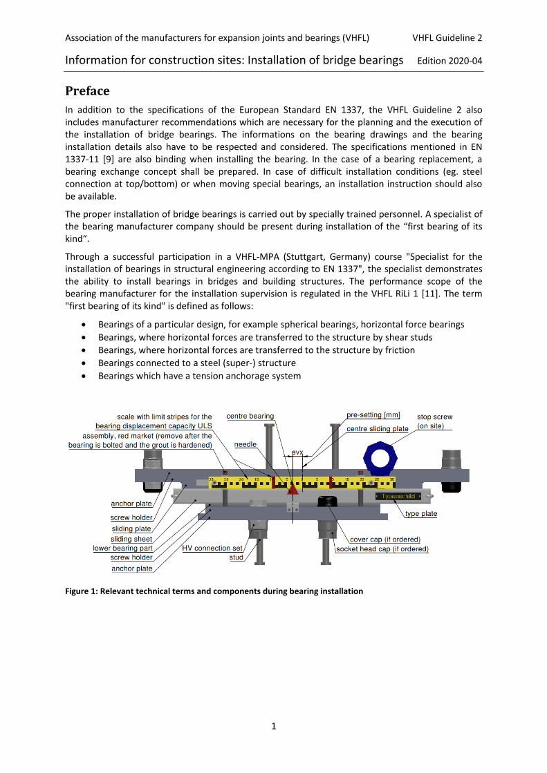
Figure 1: Relevant technical terms and components during bearing installation

Association of the manufacturers for expansion joints and bearings (VHFL) VHFL Guideline 2
Information for construction sites: Installation of bridge bearings Edition 2020-04
2
Table of Contents
1 Bearing types and systems .............................................................................................................. 3
2 Information for loading, delivery control and interim storage of bearings .................................... 3
3 Bearing labelling .............................................................................................................................. 4
4 Type plate ........................................................................................................................................ 5
5 Measuring plane on the bearing ..................................................................................................... 5
6 Sliding and tilting gap measuring points.......................................................................................... 6
7 Bearing position indicator and presettings ..................................................................................... 7
8 Bearings with anchor plates and high strength prestressed bolted connections ........................... 8
9 General instructions for the installation of bearings ....................................................................... 8
10 Measuring instruments, tools and material requirements for bearing installation ........................ 9
11 Connection of the bearings to the substructure and superstructure ........................................... 10
11.1 General Information ............................................................................................................ 10
11.2 Concrete Substructures / Grouting ..................................................................................... 10
11.3 Concrete superstructures .................................................................................................... 12
11.4 Steel superstructures .......................................................................................................... 13
12 Concreting load .............................................................................................................................. 16
13 Release of the bearings ................................................................................................................. 17
14 Commissioning of the bearings ..................................................................................................... 17
15 Bearing installation report ............................................................................................................. 17
16 Initial measurement ...................................................................................................................... 17
17 List of references ........................................................................................................................... 18
Annex 1: Bearing Protocol ................................................................................................................ 19
Annex 2: Shifting and testing of bridge bearings - test/measurement equipment ......................... 21

Association of the manufacturers for expansion joints and bearings (VHFL) VHFL Guideline 2
Information for construction sites: Installation of bridge bearings Edition 2020-04
3
1 Bearing types and systems
The European Standard EN 1337-1, Table 1 [5] describes the most common types of bearings. In
addition to the bearing number and the identification symbol, the respective degrees of freedom
(forces, movements, rotations) are specified. In addition to that, the respective bearing types are
represented schematically by the images 1a to 1f. The bearings are categorized as follows:
Type 1: Multidirectional rotatable bearings (For eg. No. 1.1 Elastomer bearing, No. 8.1
horizontal force bearing).
Type 2: Uniaxial rotatable bearings (For eg. No. 5.1 Linear rocker bearings, No. 6.1 Roller
bearings).
Type 3: Spherical and cylindrical bearings, if the horizontal force is absorbed by the curved
sliding surface (For eg. No. 3.2/3.4 and No. 7.1/7.2).
Type 4: Other bearings (For eg. No. 2.1 Pot bearing, fixed; No. 3.1 Spherical bearing,
fixed).The bearing system is shown schematically in the bearing detail plan (Figure 2). For better
orientation, the bearing shown in the bearing detail plan is marked separately in the bearing system.
Furthermore, the structurale axes A and B (X-axis = bridge longitudinal direction) and the bearing
rows 10 and 20 (Y-axis = bridge transverse direction), the north arrow, the arrangement of the
bearing position indicator and the direction of the default setting are shown (if applicable).
Figure 2: Example of a constraint-free bearing system with spherical bearings
2 Information for loading, delivery control and interim storage of bearings
Bearings are sensitive products, whose function can only be guaranteed by careful handling.
Therefore they need to be unloaded from the delivery truck using a suitable hoisting device using
approved lifting slings. Bearings should only be moved with suitable lifting slings at the points
provided for this purpose (Figure 1). Sliding plates and bearing base parts are usually aligned parallel
to each other in the production plant and connected with each other by auxiliary support structures
with the help of color coded bolted connection. This arrangement is immovable and safe for
transport. The parallelism between the bearing plates must be maintained until the bearing is
installed. The bolted connection of the transport fixation (Figure 1) should not be removed before
the bearing is firmly connected to the substructure and superstructure.
EN 1337-11 [9] specifies that the bearings must be checked for the following points immediately
upon arrival at construction site:

Association of the manufacturers for expansion joints and bearings (VHFL) VHFL Guideline 2
Information for construction sites: Installation of bridge bearings Edition 2020-04
4
visible damage, particularly to the corrosion protection. The nature and extent of any damage shall be indicated together with details of any permissible remedial action on the bearing installation drawing,
cleanliness,
security of the transportation fixation,
conformance to the installation and working drawings if this has not already been established by way of quality control or acceptance inspection,
marking on the top surface of the bearing and on the type plate as well as marking of x- and y-axisand, if necessary, of presetting on the faces of upper and bottom part of the bearing, in addition identification of measuring points at rotating gap and eventually sliding gap,
position of all means used to ensure the exact positioning and installation of the bearings, where specified,
indicating device required for movable bearings in main direction of movement, where required,
the magnitude and direction of presetting, if specified,
possibility of readjustment, if provided
temporary storage on site.
Unexpected changes or damages should be noted on the shipping documents and be immediately
reported in written form to the bearing manufacturer. Bearings that are not installed immediately
after the transport, must be stored on pallets at a suitable location and should be protected against
mechanical damages, dirt, moisture and excessive heating. It is a must to ensure adequate
ventilation in order to prevent condensation.
3 Bearing labelling
As shown in Figure 3, the X-axis (usually parallel to the longitudinal bridge axis) and the Y-axis
(usually transverse to the bridge axis) are plotted for each bearing and by color markings on the
upper side of the bearing. The front and long sides of bearing top and bottom part also marked. The
black dashed line indicates the center of the respective bearing plate, while the left and right yellow
dashed line is the optical marking. The distance between the red dashed line and the Y-axis
corresponds to the pre-setting dimension.
Figure 3: Bearing labelling in bearing detail plan (left) and on bearing (right)
Association of the manufacturers for expansion joints and bearings (VHFL) VHFL Guideline 2
Information for construction sites: Installation of bridge bearings Edition 2020-04
5
All further details are given below, which are applied on the upper anchor / bearing plate.
Bearing type according to EN 1337-1, Tabel 1 [5] with the maximum sustainable load [kN] in the ULS.
If applicable, the direction and value of the pre-setting, evx [mm] in red text.
If applicable, the direction and value of pre-rotation, φ [mrad].
Location and weight [kg] of the entire bearing.
Left and right neighbour axis (marked by circle).
A-Nr. = Order number /sheet number /control card number (serial number)
4 Type plate
Bearings are generally identified by a type plate, which is usually located on the side of the bearing
position indicator. An example of the type plate is shown in Figure 4. The layout is regulated by the
notified certification body of DIBt (usually MPA Stuttgart, Germany), which as an independent third
party determines the legal bearing identification with the EG certificate of conformity (CE mark).
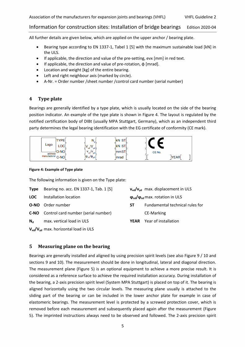
Figure 4: Example of Type plate
The following information is given on the Type plate:
Type Bearing no. acc. EN 1337-1, Tab. 1 [5]
LOC Installation location
O-NO Order number
C-NO Control card number (serial number)
Nd max. vertical load in ULS
Vxd/Vyd max. horizontal load in ULS
vxd/vyd max. displacement in ULS
ϕxd/ϕxd max. rotation in ULS
ST Fundamental technical rules for
CE-Marking
YEAR Year of installation
5 Measuring plane on the bearing
Bearings are generally installed and aligned by using precision spirit levels (see also Figure 9 / 10 and
sections 9 and 10). The measurement should be done in longitudinal, lateral and diagonal direction.
The measurement plane (Figure 5) is an optional equipment to achieve a more precise result. It is
considered as a reference surface to achieve the required installation accuracy. During installation of
the bearing, a 2-axis precision spirit level (System MPA Stuttgart) is placed on top of it. The bearing is
aligned horizontally using the two circular levels. The measuring plane usually is attached to the
sliding part of the bearing or can be included in the lower anchor plate for example in case of
elastomeric bearings. The measurement level is protected by a screwed protection cover, which is
removed before each measurement and subsequently placed again after the measurement (Figure
5). The imprinted instructions always need to be observed and followed. The 2-axis precision spirit
Association of the manufacturers for expansion joints and bearings (VHFL) VHFL Guideline 2
Information for construction sites: Installation of bridge bearings Edition 2020-04
6
level (System MPA Stuttgart) must be leveled with the measuring console at the front and sides and
it should also touch the two protruding rear pins. The measuring plane must not have a deviation
greater than 1 ‰ from the flat sliding surface (workshop setting tolerance). In case of elastomer
bearings, the measuring plane can be formed by two adjustable measuring points each on the anchor
plate or bearing plate in the direction of the main axis (Figure 6). If there is occurance that the
measuring level has been damaged during transport, this must be reported immediately to the
bearing manufacturer.
The measuring accuracy of the 2-axis precision spirit level is 0.6 ‰ (= 1 scale mark). After grouting
the inclination error of the bearing must not exceed 3 ‰ (= 5 scale marks), 5 ‰ for elastomer
bearings, plus the previously mentioned setting tolerance.
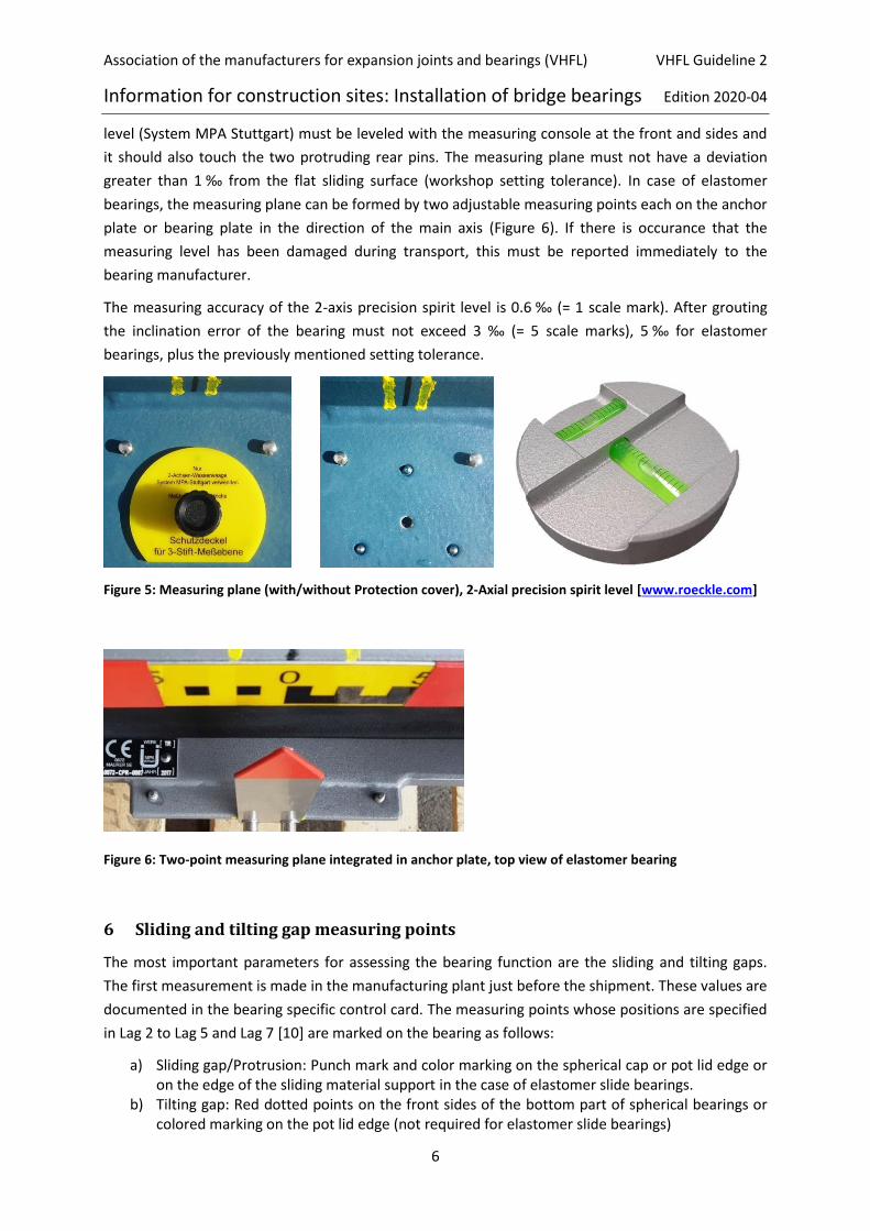
Figure 5: Measuring plane (with/without Protection cover), 2-Axial precision spirit level [www.roeckle.com]
Figure 6: Two-point measuring plane integrated in anchor plate, top view of elastomer bearing
6 Sliding and tilting gap measuring points
The most important parameters for assessing the bearing function are the sliding and tilting gaps.
The first measurement is made in the manufacturing plant just before the shipment. These values are
documented in the bearing specific control card. The measuring points whose positions are specified
in Lag 2 to Lag 5 and Lag 7 [10] are marked on the bearing as follows:
a) Sliding gap/Protrusion: Punch mark and color marking on the spherical cap or pot lid edge or on the edge of the sliding material support in the case of elastomer slide bearings.
b) Tilting gap: Red dotted points on the front sides of the bottom part of spherical bearings or colored marking on the pot lid edge (not required for elastomer slide bearings)
Association of the manufacturers for expansion joints and bearings (VHFL) VHFL Guideline 2
Information for construction sites: Installation of bridge bearings Edition 2020-04
7
The change in the sliding material thickness at non-measurable sliding gaps, for example at fixed
spherical bearings, can be detected approximately via auxiliary measurements (decrease in the
average of the tilting gap along the circumference).
The bearing manufacutrer recommend that for bearings with sliding gaps ≤ 1 mm a shorter
inspection interval shall be scheduled. For gap widths ≤ 0.2 mm, the sliding material must be
replaced immediately. For guide bearings and restaint bearings, the horizontal gap must be ≤ 2 mm
(EN 1337-8 [7]).
Figure 7: Sliding and tilting gap measuring points at the spherical bearing (left) and pot bearing (right)
7 Bearing position indicator and presettings
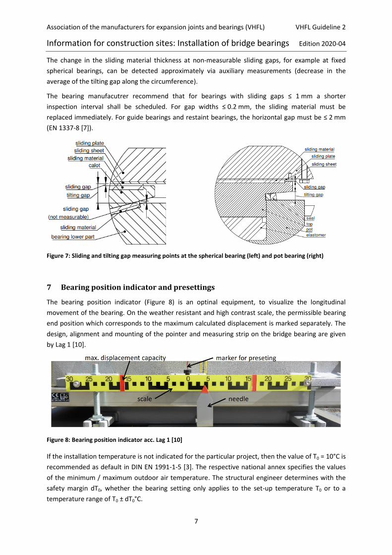
The bearing position indicator (Figure 8) is an optinal equipment, to visualize the longitudinal
movement of the bearing. On the weather resistant and high contrast scale, the permissible bearing
end position which corresponds to the maximum calculated displacement is marked separately. The
design, alignment and mounting of the pointer and measuring strip on the bridge bearing are given
by Lag 1 [10].
Figure 8: Bearing position indicator acc. Lag 1 [10]
If the installation temperature is not indicated for the particular project, then the value of T0 = 10°C is
recommended as default in DIN EN 1991-1-5 [3]. The respective national annex specifies the values
of the minimum / maximum outdoor air temperature. The structural engineer determines with the
safety margin dT0, whether the bearing setting only applies to the set-up temperature T0 or to a
temperature range of T0 ± dT0°C.
Association of the manufacturers for expansion joints and bearings (VHFL) VHFL Guideline 2
Information for construction sites: Installation of bridge bearings Edition 2020-04
8
Based on the movement values mentioned in the bearing specification, the bearing manufacturer
checks whether individual bearings need to be preset at the factory. For this purpose, the upper
bearing plate (sliding plate) is moved towards the bearing base. The direction of this shift from the
center position is indicated by a red arrow on the top of the bearing (see also Figure 3). In the
bearing detail plan, the value and the direction of the default setting are listed in the bearing
identification label. If the sliding plate position only applies to the set-up temperature T0, then the
correction value [mm/K] determined by the structural engineer to take account of the actual
installation temperature at site is noted in the bearing detail and bearing installation plan.
The members of VHFL recommend that presettings changes may only be made by a specialist from
the bearing manufacturer or at least under his supervision. In order to carry out a presetting
deviating from the bearing installation plan, a written instruction by the design engineer and/or the
responsible construction authorities is required.
8 Bearings with anchor plates and high strength prestressed bolted connections
If high strength prestressed bolts are tightened at the head of the bolts, there must be a
manufacturer specific procedure that ensures that, the same high strength prestressed bolt set is
approved to be pretensioned four times. The procedural instruction is part of the European Standard
EN1090-2, 8.5 [4].
9 General instructions for the installation of bearings
In addition to this VHFL Guideline 2, the requirements of EN 1337-11 [9] must also be taken into
consideration.
The bearings should to be installed in accordance with the specifications of the bearing installation
plan (dimensions, ground levels and positions, inclinations, lateral and longitudinal position, material
quality of the bearing joint, pre-setting). They have to be adjusted exactly according to the position
and direction in the layout as well as the height and slope in the elevation. Temporary supports shall
be used to adjust the position of the bearing. The temporary supports under bearing plates shall be
compressible under design loading (to avoid hard spots) if not removed once the bedding material
has reached the required strength.
Unless considered in the design of the structure and the bearings, the bearing shall be located so that
its position does not deviate more than 3 mm (value is recommended by VHFL acc. prEN 1337-1)
from its nominal position in any direction.
Bearing usually are installed horizontally. A deviation from the horizontal X and Y axis should not
exceed 3 ‰ and 5 ‰ for elastomer bearings after casting. For sloped bridges, the structural engineer
may prefer the bearings to be aligned in parallel to the local gradient. In any case,
-the sliding plate and the lower part of the bearing shall be parallel (such that the gradient is not
accommodated by the rotational element of the bridges)
-the alignement of the bearings must match the alignement forseen by the structural engineer
Association of the manufacturers for expansion joints and bearings (VHFL) VHFL Guideline 2
Information for construction sites: Installation of bridge bearings Edition 2020-04
9
The X-axis marked on the upper bearing plate must match with the displacement direction specified
in the bearing installation plan. The maximum deviation from the nominal displacement direction in
plane shall not exceed 3 ‰.
The direction of the pre-setting (red arrow on the upper bearing plate) has to be checked .
10 Measuring instruments, tools and material requirements for bearing
installation
The company commissioned with the bearing installation has to install the bearings under
consideration of the respective installation conditions. The following measuring devices, tools and
materials should also be available (see also Annex 2).
a) Horizontal alignment
2-axis precision spirit level d=80 mm (measuring accuracy: 1 scale=0.6 mm/m, measuring range: 5 divisions = 3mm/m),
Precision spirit level for control measurements on machined and milled bearing plates (l ≥ 200 mm, measuring accuracy ≤ 0.3 mm/m),
Allen wrench for M6 and M8 for removing the bearing position indicator (if required),
b) Tilt and slide gap measurement
1 mirror with light on a flexible holder,
1 set of telescopic gauges 8 to 12.7 mm, 12.7 to 19 mm, 19 to 32 mm,
1 set of feeler gauges from 0.1 to 2 mm, each at least 300 mm long,
1 vernier calliper up to 150 mm,
1 precision measuring tape 2 m long,
1 forehead torch/flashlight,
Angle wrench 6KT for M6 (SW 10) and M8 (SW 13) for removing the sliding surface protection (if required).
c) Mortar pouring
compulsory mixer with tub and measuring cup with 1 litre capacity,
2 to 3 small plastic buckets, if required, rope to pull up the plastic bucket on the pillar
large plastic funnel for hose d ≥ 30 mm,
smooth, transparent plastic hose, d ≥ 30 mm,
PE foil and adhesive tape to protect the bearings against pollution during casting and flat scraper/ scraper to remove concrete residues,
shuttering wood with fastening elements,
crowbar with suitable support for setting up the bearings on the axes of coordinates using a small steel angle,
for venting the mortar joint at least 2 aluminum or steel strips (about 2m long, cross section 25 mm x 1.5 - 3 mm) and 1 to 2 metal chain strands (chain link length/width/ diameter = 30/10/3 mm),
mortar system with associated product data sheet including processing information and if necessary, further product specific tools.
Association of the manufacturers for expansion joints and bearings (VHFL) VHFL Guideline 2
Information for construction sites: Installation of bridge bearings Edition 2020-04
10
d) Motar press
compulsory mixer with tub and measuring cup with 1 litre capacity,
stopper iron, 2 slide in plates, trowel,
shuttering wood with fastening elements,
PE foil and adhesive tape to protect the bearings against pollution during casting as well as flat scrapers for removing concrete residues,
mortar system with associated product data sheet including processing information and if necessary, further product specific tools.
e) Coating material
For repairing the corrosion protection, the appropriate coating materials, associated tools and cleaning utensils must be present.
11 Connection of the bearings to the substructure and superstructure
11.1 General Information
According to EN 1337-11 [9], the unreinforced mortar joint must be 2 cm to 5 cm thick. Additionally,
the layer thickness must not be less than 3 times the largest grain diameter of the additive. It must at
least correspond to very low shrinkage class and early strength class in case of cementitious mortar.
It’s recommended that only grout with a certificate of conformity may be used.
Before applying a cement bound mortar, the concrete base must be saturated with water for several
hours. Thereby no water is removed from the thin mortar layer during the set up process. Then the
non-bound water should be removed before grouting, so as not to exceed the manufacturer's
predefined maximum water level.
If epoxy resin or a metal polymer is used, the application restrictions of the technical sheets must be
followed. The manufacturer's specifications must be strictly adhered, since the mixing ratio of 2
component systems significantly affects the functionality. This also applies to the available gap
height, which can be seen in the approval.
If reaction resin mortar is used between two steel sheets of a slip resistant high strength bolted
connection, the calculated coefficient of friction must be verifiably proven, taking creep and
shrinkage behaviour into account. Mortar joints with thicknesses over 5 cm must be reinforced. The
bearing capacity of reinforced mortar joints shall be verified in accordance with DIN EN 1992 [4].
Irrespective of the type of grouting material, the product specific processing instructions of the
manufacturer must be followed. To ensure the coefficient of friction between the structure and
the bearing, which has been verified by standards or official tests, the grouting surfaces must be
free of grease and oil (especially formwork oil) and additionally the bearing plates must be
uncoated, zink flame sprayed or coated with zinc silicat. (EN 1337-1 [5]).
11.2 Concrete Substructures / Grouting
If the bearings are accurately offset and aligned (see also section 9), they are either grouted or
plugged depending on the type of mortar specified in the bearing installation plan.
Association of the manufacturers for expansion joints and bearings (VHFL) VHFL Guideline 2
Information for construction sites: Installation of bridge bearings Edition 2020-04
11
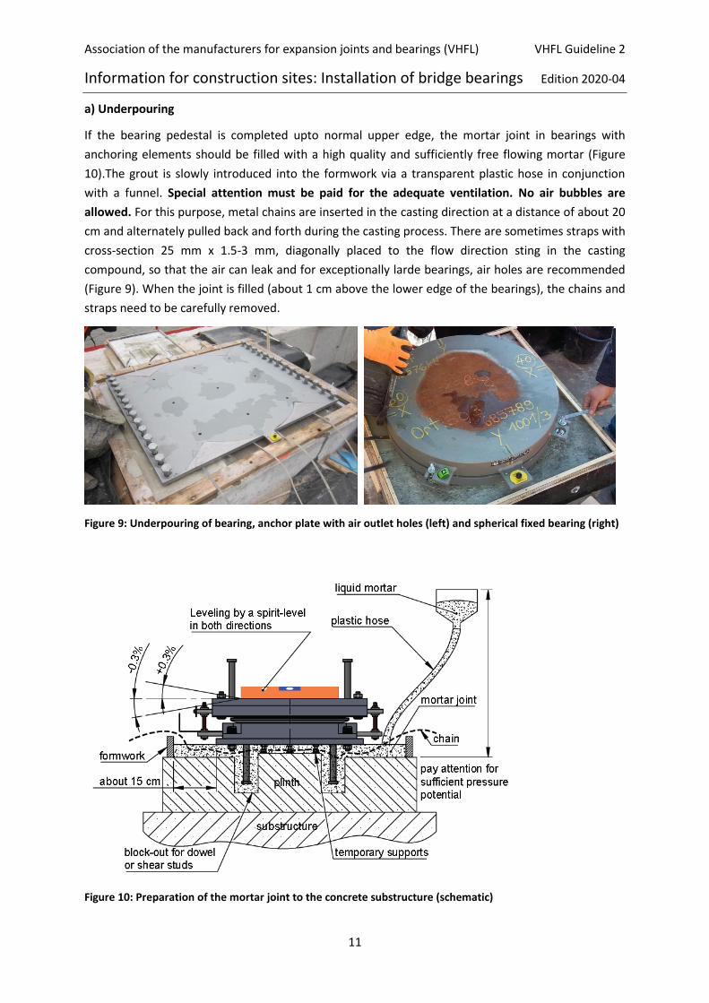
a) Underpouring
If the bearing pedestal is completed upto normal upper edge, the mortar joint in bearings with
anchoring elements should be filled with a high quality and sufficiently free flowing mortar (Figure
10).The grout is slowly introduced into the formwork via a transparent plastic hose in conjunction
with a funnel. Special attention must be paid for the adequate ventilation. No air bubbles are
allowed. For this purpose, metal chains are inserted in the casting direction at a distance of about 20
cm and alternately pulled back and forth during the casting process. There are sometimes straps with
cross-section 25 mm x 1.5-3 mm, diagonally placed to the flow direction sting in the casting
compound, so that the air can leak and for exceptionally larde bearings, air holes are recommended
(Figure 9). When the joint is filled (about 1 cm above the lower edge of the bearings), the chains and
straps need to be carefully removed.
Figure 9: Underpouring of bearing, anchor plate with air outlet holes (left) and spherical fixed bearing (right)
Figure 10: Preparation of the mortar joint to the concrete substructure (schematic)

Association of the manufacturers for expansion joints and bearings (VHFL) VHFL Guideline 2
Information for construction sites: Installation of bridge bearings Edition 2020-04
12
b) Underplugging
Packing mortar exhibits a stiff consistency. In the case of large bearings, undercoating is carried out
against a wooden strip in the middle, which is wedged in the longitudinal direction underneath the
bottom part of the bearing. If the cavity is half filled, the wooden strip is removed and the mortar is
plugged against the mass already applied. Particularly in warm weather and with large containers, it
is advisable to process the mortar in partial quantities.
Another possibility is to work with two men and two darning irons. The mortar is pushed inside from
one side upto the centre of the bearing and held against the other side with a darning iron. This
process is repeated as often as necessary until the material filled inside offers sufficient resistance in
order to plug the remaining joint towards the outer edges without any opposite. This procedure
should only be used by appropriately trained personnel.
In case of small bearing plates, grouting from one side against a joint opening closed on three sides is
a proven reliable option.
Irrespective of the method chosen, the contact pressure of the darning iron must always be high
enough to ensure that no cavities remain in the mortar bed.
11.3 Concrete superstructures
If the bearing connects directly to a precast superstructure member, see 11.2
Usually the superstructure is concreted directly onto the bearing, whereby the forwork is brought as
close as possible to the bearing. In order to avoid moistening the bearing with cement slurry, the
remaining gap between the formwork and the upper bearing plate must be sealed e.g. using
polyurethane foam. The insertion of a foil is not permitted. If necessary, precautions must be taken
to ensure that the bearing always remains in position even if the formwork expands due to
temperature. The possibility of loosening the bolts of the auxiliary support structure marked in red
on time must also be taken into account. Ensure that the auxillary support elements are accessible
and can be disconnected on the the bearing is firmly connected to both the sub- and the
superstructure, i.e. the concrete or mortar is extensively hardened. The “activation” of the sliding
bearing should be confirmed by the structural engineer, as there are several exceptions. For
example:
In case of prestressed concrete bridges, the bolted connections must be removed before the prestressing tendons are tensioned
In case of change / relocation of the fixed point during construction, auxillary support elements may be desired to remain fastened beyond the firm connection of the bearing to sub- and superstructure
In case of bearings with high torsional resistance (pot bearings, elastomeric bearings with sliding
elements), it is possible to replace the metallic bolts or threaded rods of the auxiliary support
structure with plastic fasteners (e.g. polyamide). But it is feasible only after the bearing has been
offset and aligned. If this is intended, then the instructions on the bearing detail plans must be
strictly followed. In this case, accessibility before stripping the formwork does not have to be
guaranteed, as the plastic bolted connection already fails under low load. After stripping the
formwork, all plastic residues remaining on the bearing must be removed.
Association of the manufacturers for expansion joints and bearings (VHFL) VHFL Guideline 2
Information for construction sites: Installation of bridge bearings Edition 2020-04
13
11.4 Steel superstructures
Generally bridge bearings are installed horizontally considering the maximum permissible inclination
error (refer chapter 5). For this reason, a permanent inclination of the superstructure must either be
mathematically taken into account and the bearings are pre-rotated or the wedge shaped gap
between the bearing and the steel superstructure must be compensated (see also section 9). Along
with this, the flatness tolerance of the steel contact surfaces (bridge bearing and steel
superstructure) specified in EN 1337-2 [6] must not be exceeded for plain bearings 0.0003 x DLP or 0.2
mm (DLP = diagonal of the bearing plate) and for elastomer bearings 0.003 x DE or 1 mm (DE =
diagonal of elastomer bearing).
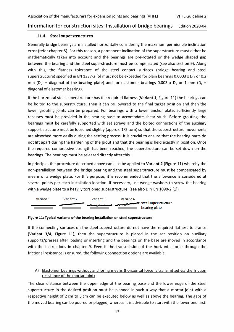
If the horizontal steel superstructure has the required flatness (Variant 1, Figure 11) the bearings can
be bolted to the superstructure. Then it can be lowered to the final target position and then the
lower grouting joints can be prepared. For bearings with a lower anchor plate, sufficiently large
recesses must be provided in the bearing base to accomodate shear studs. Before grouting, the
bearings must be carefully supported with set screws and the bolted connections of the auxiliary
support structure must be loosened slightly (approx. 1/2 turn) so that the superstructure movements
are absorbed more easily during the setting process. It is crucial to ensure that the bearing parts do
not lift apart during the hardening of the grout and that the bearing is held exactly in position. Once
the required compressive strength has been reached, the superstructure can be set down on the
bearings. The bearings must be released directly after this.
In principle, the procedure described above can also be applied to Variant 2 (Figure 11) whereby the
non-parallelism between the bridge bearing and the steel superstructure must be compensated by
means of a wedge plate. For this purpose, it is recommended that the allowance is considered at
several points per each installation location. If necessary, use wedge washers to screw the bearing
with a wedge plate to a heavily torsioned superstructure. (see also DIN EN 1090-2 [1])
Figure 11: Typical variants of the bearing installation on steel superstructure
If the connecting surfaces on the steel superstructure do not have the required flatness tolerance
(Variant 3/4, Figure 11), then the superstructure is placed in the set position on auxiliary
supports/presses after loading or inserting and the bearings on the base are moved in accordance
with the instructions in chapter 9. Even if the transmission of the horizontal force through the
frictional resistance is ensured, the following connection options are available.
A) Elastomer bearings without anchoring means (horizontal force is transmitted via the friction resistance of the mortar joint)
The clear distance between the upper edge of the bearing base and the lower edge of the steel
superstructure in the desired position must be planned in such a way that a mortar joint with a
respective height of 2 cm to 5 cm can be executed below as well as above the bearing. The gaps of
the moved bearing can be poured or plugged, whereas it is advisable to start with the lower one first.

Association of the manufacturers for expansion joints and bearings (VHFL) VHFL Guideline 2
Information for construction sites: Installation of bridge bearings Edition 2020-04
14
The comments of the previous subchapters 11.1 and 11.2 apply, in particular to the notes on
producing the bubble free mortar contact surface. Once they have reached the required compressive
strength, the presses are relieved and the superstructure is set down on the bearings and the
auxiliary support structures are loosened.
B) Bearing with mortar joint and bolted connection to the steel superstructure
The clear distance between the upper edge of the bearing base and the lower edge of the steel
superstructure in the desired position must be planned in such a way that a mortar joint with a
height of 2 cm to 5 cm can be prepared under the bearings and the gap width dependent on the
material (cement, synthetic resin or metal poylmer) can be prepared above the bearings. It is also
recommended that, the lining plate (possibly wedge shaped) with an average thickness of at least
18 mm is inserted between the bearing plate and the steel superstructure so that the contact joint is
not damaged when the bearing is exchanged.
The bearings are installed as follows:
In first step, the wedge plate is first separated from the bearing. According to the manufacturer's instructions, either a filler (e.g. MM1018 or similar) is applied in an x-shaped manner and then pressed onto the steel superstructure with screws, or the wedge plate is screwed to the steel superstructure in the desired position, shuttered and the remaining gap is completely filled with a grouting/injection system. In both cases, the wedge plate is horizontally aligned with a machine spirit level (chapter 10).
Bearings without wedge plates are bolted completely to the steel superstructure and the mortar system dependent gap dimension is adjusted. The bearing is then shuttered horizontally with the 2-axis spirit level and the remaining cavity is completely filled.
The bearing must be cleaned immediately from squeezed out filler material or pouring grout.
Once the filler material has hardened, conitnue in the same way as for variant 1.
C) Bearing with mortar joint and weld seam connection for steel superstructure
The clear distance between the upper edge of the bearing base and the lower edge of the
superstructure must be prepared as described in section B1. A lining plate should also be used.
The bearings are installed as follows:
After the bearing has been moved offset and aligned using temporary supports, a steel frame is welded to the steel superstructure on site. The size of the frame must be designed and dimensioned, in order to fit around the upper bearing plate with at least 10 mm clearance.
The gaps between the bearing and the structure are shuttered and the lower joint is prepared as described in subsection 11.2. Thereafter, the upper joint is grouted by the filling and vent holes provided on the steel superstructure.

Association of the manufacturers for expansion joints and bearings (VHFL) VHFL Guideline 2
Information for construction sites: Installation of bridge bearings Edition 2020-04
15
Alternative 1
o If there is a bracket/pin on the steel superstructure for shear force transmission, it is recommended that the filler plate bolted to the bearing is trough-shaped. The webs later serve as the formwork or shuttering. After the lower bearing joint has been produced as described in subchapter 11.2 the trough is cast and a full surface frictional connection in horizontal and vertical direction to the steel superstructure is executed.
Once the mortar has reached the required compressive strength, the jacks are relieved, the superstructure is placed on the bearings and the auxiliary support structures are loosened.
Alternative 2
o A filler plate (wedge shaped if applicable) is welded all around to the steel superstructure, leaving a gap of ≤ 10 mm in the vertical direction. Metal polymer (e.g. MM1018 or similar) is injected into the cavity. Due to the high requirements of material processing and the venting mechanism, the injection of the material should only be carried out by trained personnel. Once the filling material has hardened, the bearing is bolted to the lining plate via a blind hole connection. The further procedure is the same as for variant 1.
Spontaneous individual customised solutions, which are easy and necessary during replacement of a
bearing are permissible. This solution must be agreed by the company carrying out the construction
work, the planning office, the test engineer and the bearing manufacturer. It should also be
documented in a bearing replacement manual. Figure 12 / Figure 13 / Figure 14 show examples of
the possible connections to the steel superstructure.
Figure 12: Grouting to the concrete substructure, welding to the steel superstructure
Association of the manufacturers for expansion joints and bearings (VHFL) VHFL Guideline 2
Information for construction sites: Installation of bridge bearings Edition 2020-04
16
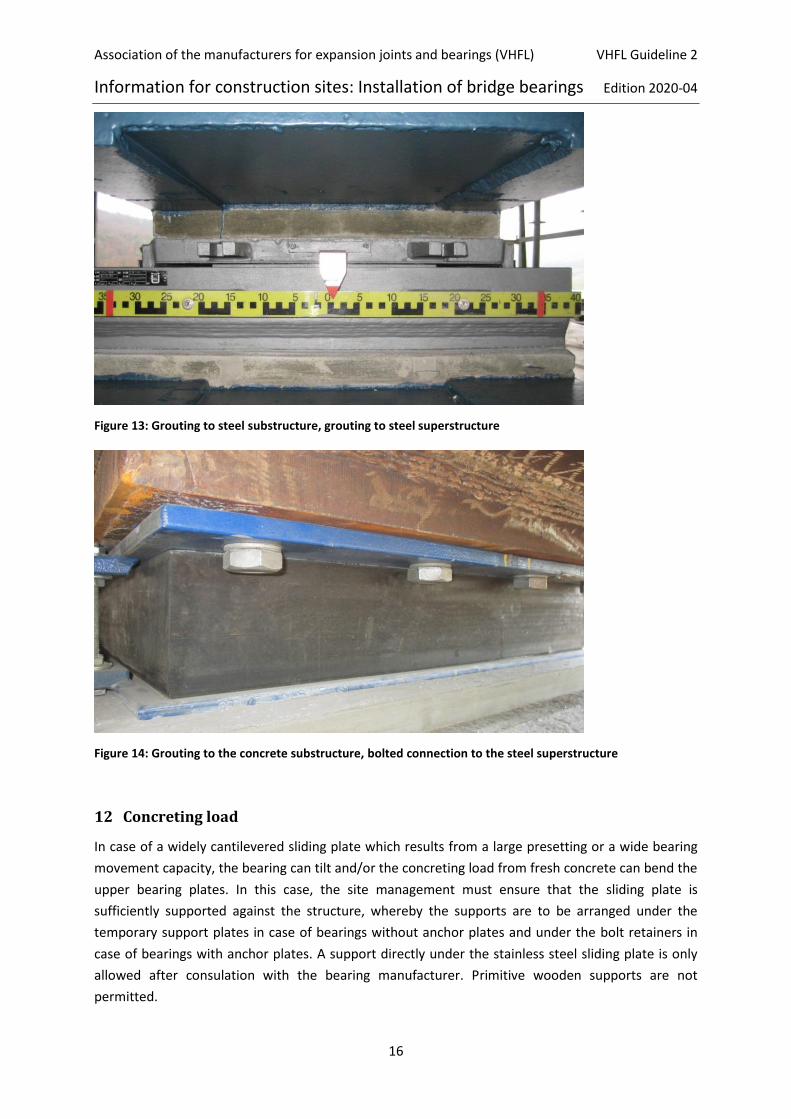
Figure 13: Grouting to steel substructure, grouting to steel superstructure
Figure 14: Grouting to the concrete substructure, bolted connection to the steel superstructure
12 Concreting load
In case of a widely cantilevered sliding plate which results from a large presetting or a wide bearing
movement capacity, the bearing can tilt and/or the concreting load from fresh concrete can bend the
upper bearing plates. In this case, the site management must ensure that the sliding plate is
sufficiently supported against the structure, whereby the supports are to be arranged under the
temporary support plates in case of bearings without anchor plates and under the bolt retainers in
case of bearings with anchor plates. A support directly under the stainless steel sliding plate is only
allowed after consulation with the bearing manufacturer. Primitive wooden supports are not
permitted.
Association of the manufacturers for expansion joints and bearings (VHFL) VHFL Guideline 2
Information for construction sites: Installation of bridge bearings Edition 2020-04
17
13 Release of the bearings
If the bearing is firmly connected to the substructure and superstructure, before prestressing the
colour marked bolts of the auxiliary support structures must be loosened and any remaining free
tapped holes must be closed with sealing plugs. This process has to be done immediately after
hardening of the mortar joints. This procedure is not necessary, if the auxiliary support structures are
provided with polyamide bolt after the installation. If there are fixed adjusting bolts on the bearing,
check again whether these have been torqued back and relieved. If the bearings have been aligned
by temporary supports for example with conical clamping washers or set screw tappets these remain
in the structure.
14 Commissioning of the bearings
After removal of the shuttering or formwork, the bearings must be cleaned and any damage to the
corrosion protection must be repaired. Information on the possibilities of corrosion protection repair
can be found in ISO 12944 and must be consulted with the bearing manufacturer. Since sliding
materials or elastomer components can be easily damaged, all cleaning and repair work (e.g.
grinding) must be carried out very carefully. It is generally forbidden to work with compressed air,
fire, fuels or chemical agents in the vicinity of a bridge bearing. If blasting work is carried out next to
the bearing, the entire bearing must be protected from blasting material.
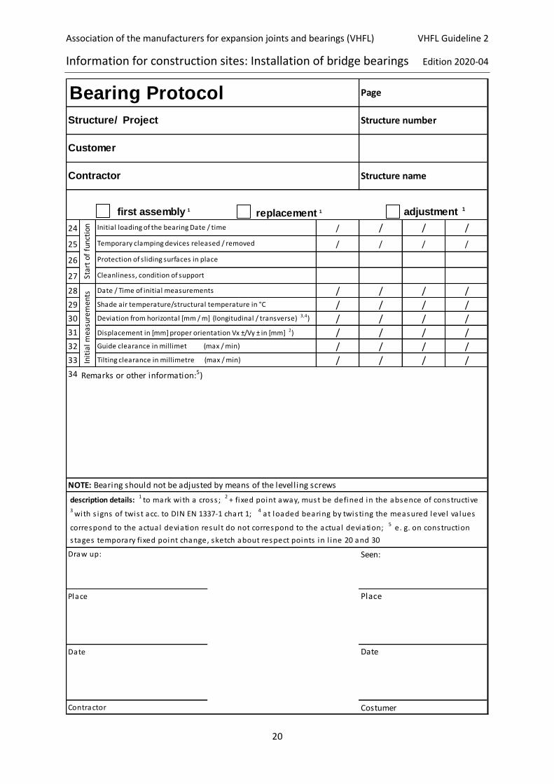
15 Bearing installation report
Templates for bearing installation reports are provided in Annex 1 and in DIN 1337-11 [9]. It is mostly
possible to adapt or supplement the forms to the respective installation situation.
If the bearing manufacturer supervises the complete installation process, then the respective
specialist will mention the notes in the lines "Before installation" and "Installation" and will confirm
in the line "Remarks" the instruction of the executing installation company in the correct installation
of the bearing. All other bearing records of the previously instructed bearing type are filled in by the
local site management independently, unless otherwise agreed contractually.
16 Initial measurement
The initial measurement (commissioning inspection) at the beginning of the bearing’s service life) has
to be arranged by the contractor. He is free to appoint a specialist of the bearing manufacturer or a
third party supervising body. The client carries out corresponding measurements during the first
inspection of the structure in accordance with the main inspection. For these measurements, the
horizontal position at the measuring plane of the bearings shall be checked, the sliding and tilting
gaps shall be measured at the marked points and the displacement as a function of the mean
structural temperature . The results of the zero measurement shall be documented in the respective
files. For this reason, text fields are already reserved in the bearing protocol document. The required
test and measuring equipment and tools (Annex 2) as well as any scaffolding required must be
provided by the contractor.

Association of the manufacturers for expansion joints and bearings (VHFL) VHFL Guideline 2
Information for construction sites: Installation of bridge bearings Edition 2020-04
18
17 List of references
[1] DIN EN 1090-2 (2018-09) Execution of steel structures and aluminium structures – Part 2:
Technical requirements for steel structures.
[2] DIN EN 1990/NA/A1 (2012-08) Basis of structural design.
[3] DIN EN 1991-1-5 (2010-12) Actions on structures – Part 1-5: General actions – Thermal actions.
[4] DIN EN 1992-1 (2011-01) Design of concrete structures – Part 1-1: General rules and rules for
buildings.
[5] EN 1337-1 (2001-02) Structural bearings – Part 1: General design rules.
[6] EN 1337-2 (2004-07) Structural bearings – Part 2: Sliding elements.
[7] EN 1337-8 (2008-01) Structural bearings – Part 8: Gide bearings and Restraint bearings.
[8] EN 1337-10 (2003-11) Structural bearings – Part 10: Inspection und maintenance.
[9] EN 1337-11 (1998-04) Structural bearings – Part 11: Transport, storage und installation.
[10] Richtzeichnungen für Ingenieurbauten RiZ-ING (2015-12), Lag 1 – 11, Federal Ministry of
Transport and Digital Infrastructure, Germany.
[11] VHFL RiLi 1 (2010-11) Leistungsumfang des Lagerherstellers bei der Einbauaufsicht Lager.
Products recommended by the VHFL for bearing grouting
Product name; Manufacturer homepage
Contact surface Steel-Steel (liquid/pasty)
MM1018FL/MM1018P; http://diamant-polymer.de/
Contact surface Steel-Concrete (grouting mortar, pouring)
PARGEL V1/50; www.pagel.com
Silikal R17; www.silikal.de,
Contact surface Steel-Concrete (grouting mortar, press)
PARGEL V14/40; www.pagel.com
BETEC 340; www.bcr.at
Association of the manufacturers for expansion joints and bearings (VHFL) VHFL Guideline 2
Information for construction sites: Installation of bridge bearings Edition 2020-04
19
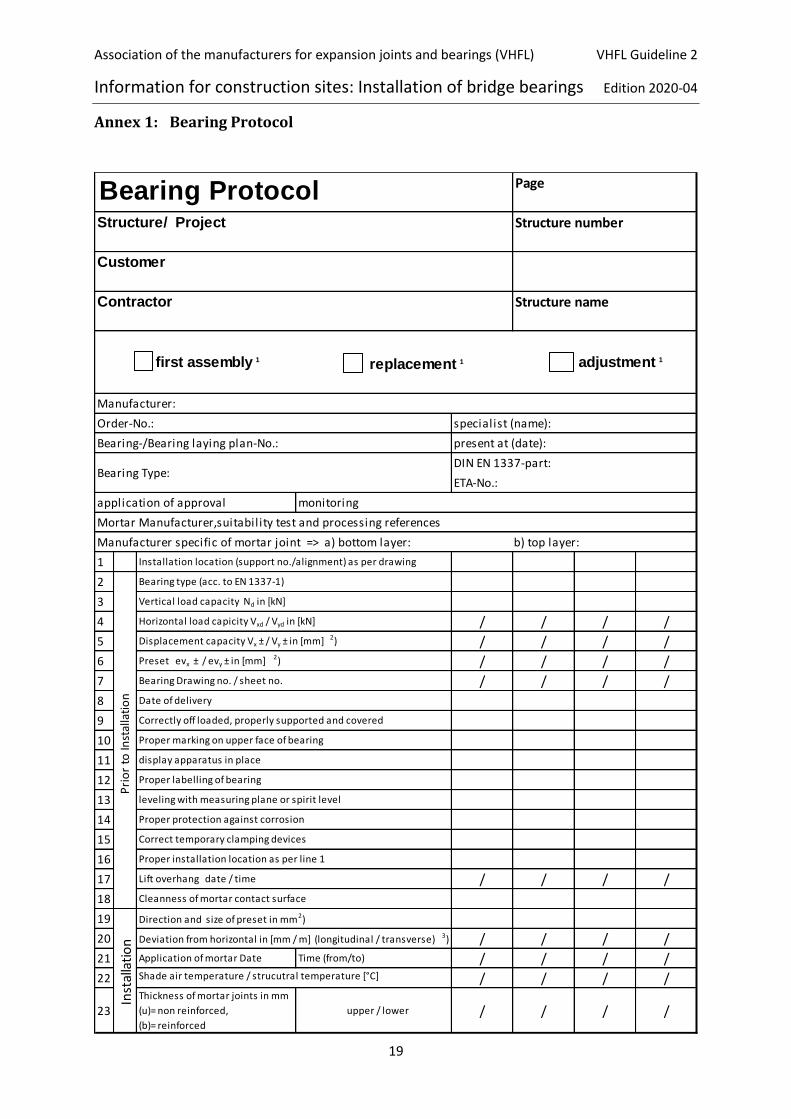
Annex 1: Bearing Protocol
first assembly 1 adjustment 1
DIN EN 1337-part:
ETA-No.:
monitoring
Mortar Manufacturer,suitability test and processing references
Manufacturer specific of mortar joint => a) bottom layer: b) top layer:
1
2
3
4 / / / /
5 / / / /
6 / / / /
7 / / / /
8
9
10
11
12
13
14
15
16
17 / / / /
18
19
20 / / / /
21 Application of mortar Date Time (from/to) / / / /
22 / / / /
23Thickness of mortar joints in mm
(u)= non reinforced,
(b)= reinforced
upper / lower / / / /
Lift overhang date / time
Cleanness of mortar contact surface
Inst
alla
tio
n
Direction and size of preset in mm2)
Deviation from horizontal in [mm / m] (longitudinal / transverse) 3)
Shade air temperature / strucutral temperature [°C]
Proper installation location as per line 1
Pri
or
to In
stal
lati
on
Bearing type (acc. to EN 1337-1)
Vertical load capacity Nd in [kN]
Horizontal load capicity Vxd / Vyd in [kN]
Displacement capacity Vx ± / Vy ± in [mm] 2)
Preset evx ± / evy ± in [mm] 2)
Bearing Drawing no. / sheet no.
Date of delivery
Correctly off loaded, properly supported and covered
Proper marking on upper face of bearing
display apparatus in place
Proper labelling of bearing
leveling with measuring plane or spirit level
Proper protection against corrosion
Correct temporary clamping devices
Installation location (support no./alignment) as per drawing
replacement 1
Manufacturer:
Order-No.: specialist (name):
Bearing-/Bearing laying plan-No.: present at (date):
Bearing Type:
application of approval
Contractor Structure name
Bearing Protocol Page
Structure/ Project Structure number
Customer
Association of the manufacturers for expansion joints and bearings (VHFL) VHFL Guideline 2
Information for construction sites: Installation of bridge bearings Edition 2020-04
20
first assembly 1 replacement 1 adjustment 1
24 / / / /
25 / / / /
26
27
28 / / / /
29 / / / /
30 / / / /
31 / / / /
32 / / / /
33 / / / /
34
Seen:
Place Place
Date Date
Contractor Costumer
correspond to the actual deviation resul t do not correspond to the actual deviation; 5 e. g. on construction
s tages temporary fixed point change, sketch about respect points in l ine 20 and 30
Draw up:
NOTE: Bearing should not be adjusted by means of the levelling screws
description details: 1 to mark with a cross ; 2 + fixed point away, must be defined in the absence of constructive
3
with s igns of twis t acc. to DIN EN 1337-1 chart 1; 4 at loaded bearing by twis ting the measured level va lues
Init
ial m
easu
rem
ents
Date / Time of initial measurements
Shade air temperature/structural temperature in °C
Deviation from horizontal [mm / m] (longitudinal / transverse) 3,4)
Displacement in [mm] proper orientation Vx ±/Vy ± in [mm] 2)
Guide clearance in millimet (max / min)
Tilting clearance in millimetre (max / min)
Remarks or other information:5)
Star
t o
f fu
nct
ion Initial loading of the bearing Date / time
Temporary clamping devices released / removed
Protection of sliding surfaces in place
Cleanliness, condition of support
Contractor Structure name
Bearing Protocol Page
Structure/ Project Structure number
Customer
VHFL Guideline 2
Version 2020-04
21
Annex 2: Shifting and testing of bridge bearings - test/measurement equipment
The following testing/measuring equipment and tools have proved to be necessary or helpful for the
professional shifting and testing of bridge bearings.
Test and measurement equipment
Tilting and sliding gap measurement - Feeler gauge sets, e.g. in the lengths 300 / 500 - Telescopic gauge sets, e.g. with measuring ranges from 5 to 30 mm - Vernier calipers up to 150 mm (digital) Bearing position - Depth gauge - Angles - Metal ruler Horizontal Alignment - 2-Axis-Precision Spirit Level (System MPA Stuttgart; www.roeckle.com)
Measuring accuracy: 1 Graduation Line = 0.6 mm/m Measurement range: 5 Graduation Line = 3 mm/m
- Tripod and measuring plate for 2-axis precision spirit level - Inclination measuring instrument /Machine spirit level 0.3 mm/m Other - Contact Thermometer - Coating thickness measurement device - Straightedge, For e.g. in the lengths 200/300/500 mm - Precision measurement tape Tools - Torch (with spare batteries) - Mirror - Set of open-end wrenches (matched to stock) - Set of hexagon socket wrench - Set of socket spanners or ring ratchet wrenches - Set of screwdrivers - Scraper Miscellaneous - Cleaning agent/Solvent/Clothes - Clipboard - Bearing Drawings / Bearing Transfer Plans / Bearing End Control Cards - Protocol templates - Writing things - Robust container for test/measuring equipment and tools - Rope for transporting the container to the installation site (if necessary) - Handgloves - Safety helm - Safety footwear and goggles - Hearing protection