Embed Size (px)
Citation preview

192.4mm
Manually operated handle
(Unclamping position)
53mm
NewNew
CKZT25
CKZT32
Lightweight Weight : 580 g (ø25)
Compact Width : 34 mm Height : 192.4 mm (ø25, Arm opening angle: 90°)
Clamping force : 1100 N (ø32, Arm length: 50 mm, 0.5 MPa pressure)
Power Clamp Cylinderø25, ø32
For material handling andclamping of small workpieces
Compact Type
Force amplification with a toggle mechanism and lock functionCan hold a clamped state when supply pressure drops or residual pressure is released
Spatter-proof constructionFully closed structure prevents the intrusion of spatter
Equipped with a proximity switchthat can be used in weldingmagnetic fields
A model with a manually operated handle is available.For manual workpiece setting processes
High clamping force
Lightweight
Lock function
Compact
34 mm
16-E682
INFORMATION
CKZT -X2797 (Base Type)
-X2798 (With Manually Operated Handle)
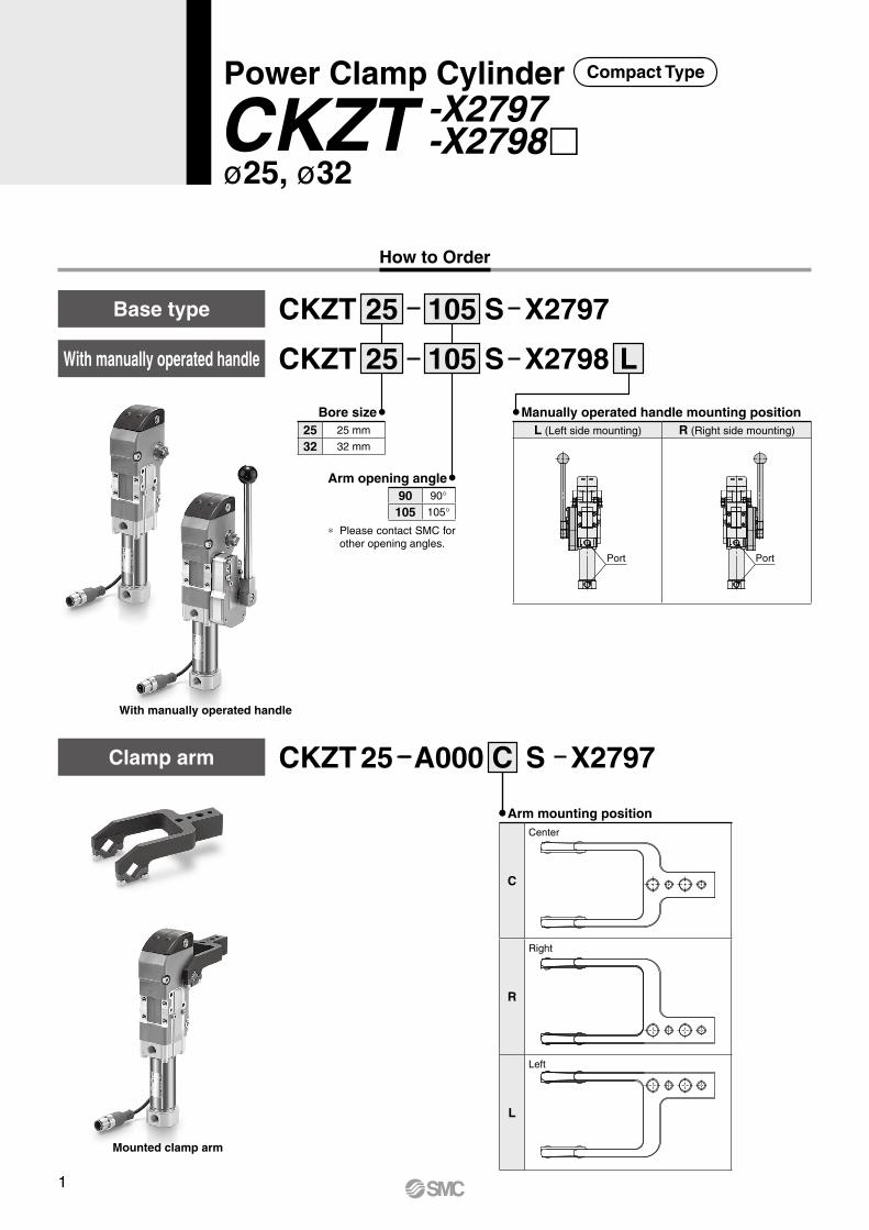
Bore size25 25 mm
32 32 mm
CKZT X2797
X2798CKZT
S
S
105
105 L
25
25
Base type
Arm opening angle
Clamp arm
How to Order
Manually operated handle mounting positionL (Left side mounting) R (Right side mounting)
Port Port
90 90°105 105°
* Please contact SMC for other opening angles.
Arm mounting position
C
Center
R
Right
L
Left
CKZT A00025 C S X2797
Mounted clamp arm
With manually operated handle
With manually operated handle
Power Clamp Cylinder
CKZT -X2797 -X2798
ø25, ø32
Compact Type
1
Top cover
SpacerBolt
Power Clamp Cylinder CKZT -X2797 -X2798
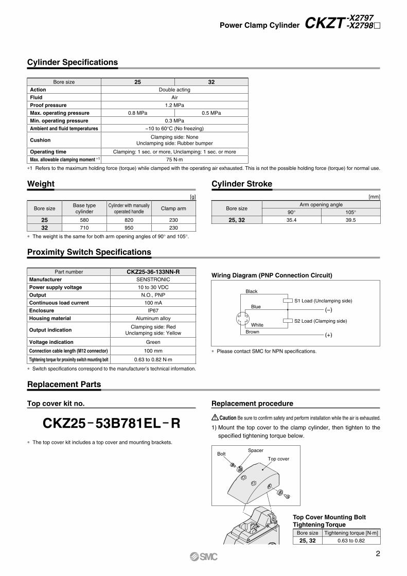
CKZ25 53B781EL R
Cylinder Specifications
Proximity Switch Specifications
Weight[g]
* Switch specifications correspond to the manufacturer’s technical information.
* Please contact SMC for NPN specifications.
Black
S1 Load (Unclamping side)
S2 Load (Clamping side)
(−)
(+)BrownWhite
Blue
2
3
1
4
Bore size 25 32Action Double acting
Fluid Air
Proof pressure 1.2 MPa
Max. operating pressure 0.8 MPa 0.5 MPa
Min. operating pressure 0.3 MPa
Ambient and fluid temperatures −10 to 60°C (No freezing)
CushionClamping side: None
Unclamping side: Rubber bumper
Operating time Clamping: 1 sec. or more, Unclamping: 1 sec. or more
Max. allowable clamping moment *1 75 N·m
Bore sizeBase typecylinder
Cylinder with manually operated handle
Clamp arm
25 580 820 230
32 710 950 230
Part number CKZ25-36-133NN-RManufacturer SENSTRONIC
Power supply voltage 10 to 30 VDC
Output N.O., PNP
Continuous load current 100 mA
Enclosure IP67
Housing material Aluminum alloy
Output indicationClamping side: Red
Unclamping side: Yellow
Voltage indication Green
Connection cable length (M12 connector) 100 mm
Tightening torque for proximity switch mounting bolt 0.63 to 0.82 N·m
*1 Refers to the maximum holding force (torque) while clamped with the operating air exhausted. This is not the possible holding force (torque) for normal use.
* The weight is the same for both arm opening angles of 90° and 105°.
Cylinder Stroke[mm]
Bore sizeArm opening angle
90° 105°25, 32 35.4 39.5
Wiring Diagram (PNP Connection Circuit)
Replacement Parts
Top cover kit no. Replacement procedure
1) Mount the top cover to the clamp cylinder, then tighten to the specified tightening torque below.
Top Cover Mounting BoltTightening Torque
Bore size Tightening torque [N·m]
25, 32 0.63 to 0.82
Caution Be sure to confirm safety and perform installation while the air is exhausted.
* The top cover kit includes a top cover and mounting brackets.
2
CB
E G1/8Clamping port
G1/8Unclamping port
34
40
52
D
53
34
3
13
44A
A
28+
0.1
0
93
16
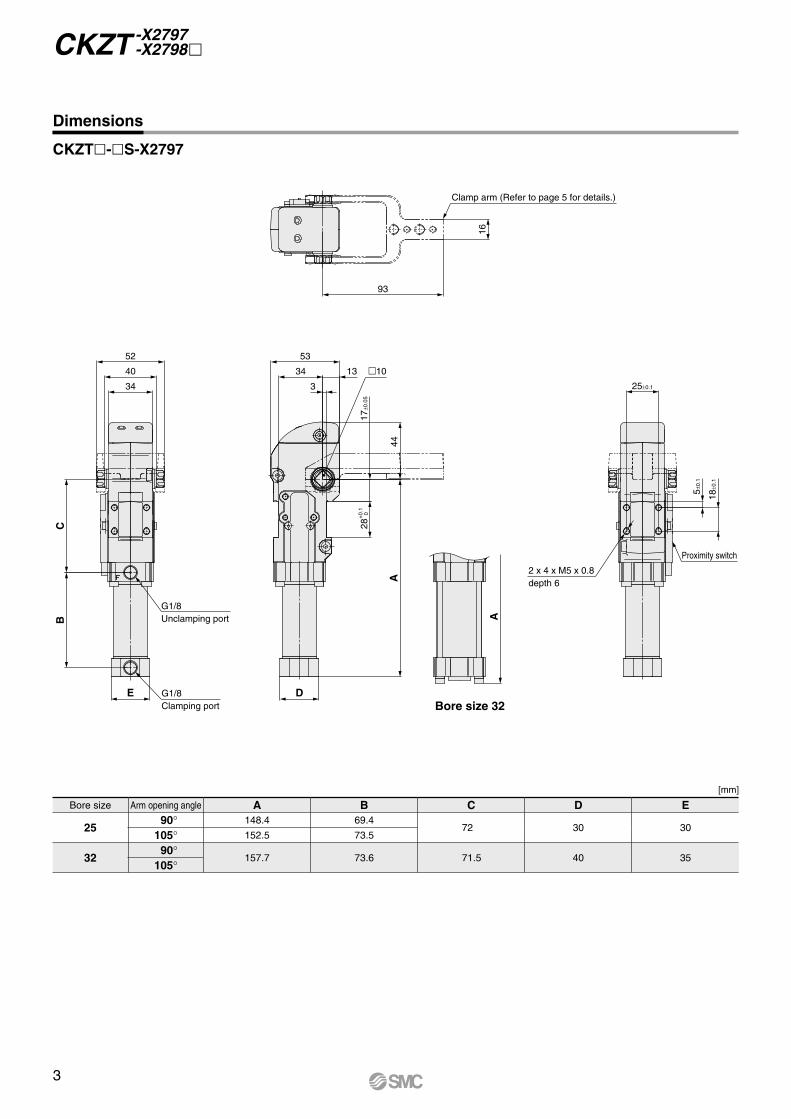
Clamp arm (Refer to page 5 for details.)
25±0.1
Proximity switch
2 x 4 x M5 x 0.8depth 6
18±0
.1
5±0.
1
17±0
.05
10
Bore size 32
CKZT -X2797 -X2798
Dimensions
Bore size Arm opening angle A B C D E
2590° 148.4 69.4
72 30 30105° 152.5 73.5
3290°
157.7 73.6 71.5 40 35105°
[mm]
CKZT-S-X2797
3
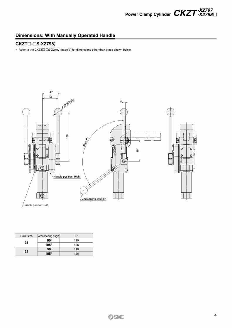
Max
. F°
47
42
ø20 (Black)
130
Handle position: Right
Handle position: Left
Unclamping position
55
4
Power Clamp Cylinder CKZT -X2797 -X2798
Dimensions: With Manually Operated Handle
CKZT-S-X2798R L
* Refer to the CKZT-S-X2797 (page 3) for dimensions other than those shown below.
Bore size Arm opening angle F°
2590° 110
105° 126
3290° 110
105° 126
4
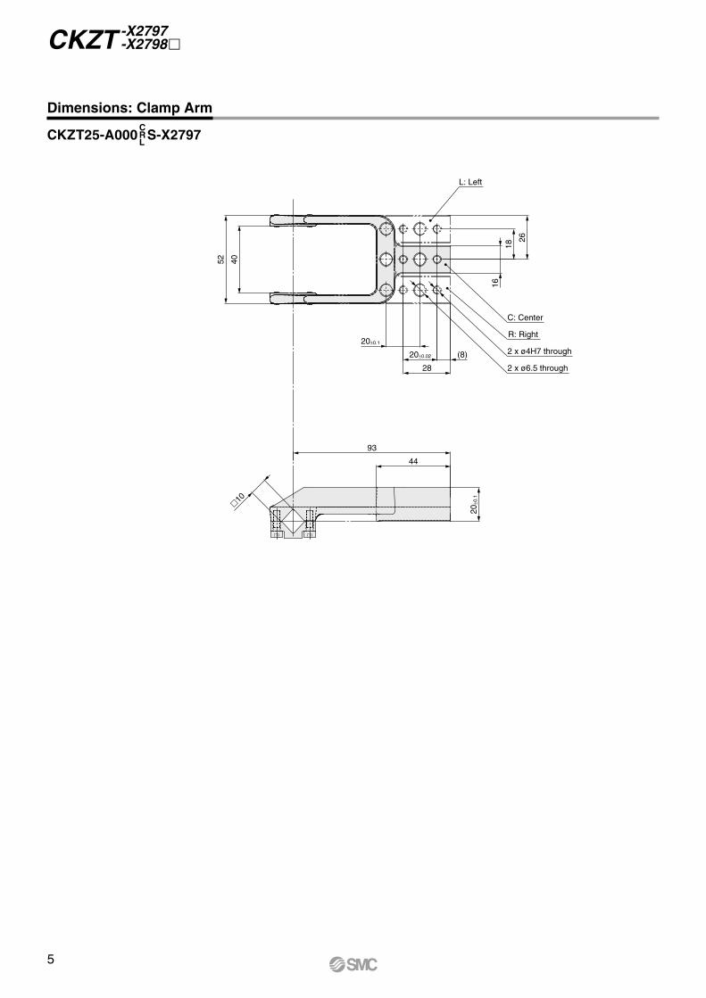
L: Left
26
18
16
28
20±0.02 (8)
20±0.1
52 40
44
93
20±0
.1
2 x ø6.5 through
2 x ø4H7 through
R: Right
C: Center
10
CKZT -X2797 -X2798
Dimensions: Clamp Arm
CKZT25-A000 S-X2797CRL
5
Extension armFulcrum
Load cell
Shim
Clamping block
Clamp arm
Arm length
Fulcrum
L
Clamp arm
Load center of gravity
Shim
Clamping block
Extension arm
Arm length
Clamp arm
Clamping block
Shim
Clamping positionExtension arm
Load center of gravity
Fulcrum
0.8 MPa
0.5 MPa
0.3 MPa
50 100 150 200
Max
. cla
mpi
ng fo
rce
[N]
Arm length [mm]
0.5 MPa
0.3 MPa
50 100 150 200
Cla
mpi
ng fo
rce
[N]
Arm length [mm]
Bore Size: 25 Bore Size: 321200
1000
800
600
400
200
0
1200
1000
800
600
400
200
0
3
2.5
2
1.5
1
0.5
050 75 100 125 150 175 200
Allo
wab
le lo
ad m
ass
[kg]
Distance to the center of gravity [mm]
Arm opening angle: 105°
Arm opening angle: 90°
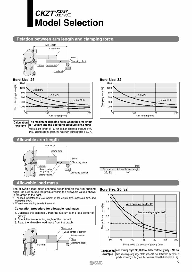
Relation between arm length and clamping force
Allowable load mass
Allowable arm length
Bore Size: 25, 32
Calculationexample
The maximum clamping force when the arm length is 100 mm and the operating pressure is 0.3 MPa:With an arm length of 100 mm and an operating pressure of 0.3 MPa, according to the graph, the maximum clamping force is 200 N.
CKZT -X2797 -X2798m
Model Selection
The allowable load mass changes depending on the arm opening angle. Be sure to use the product within the allowable values shown in the graph to the right.∗ The load indicates the total weight of the clamp arm, extension arm, and
clamping block.∗ When the operating time is 1 second
Calculation procedure for allowable load mass1. Calculate the distance L from the fulcrum to the load center of
gravity.2. Check the arm opening angle of the product.3. Read the allowable load mass from the graph.
Calculationexample
Arm opening angle: 90°, Distance to the center of gravity L: 125 mmWith an arm opening angle of 90° and a 125 mm distance to the center of gravity, according to the graph, the maximum allowable load mass is 1 kg.
[mm]Bore size Allowable arm length25, 32 200
6
Fulcrum
Clamp arm
Clamp armmounting bolt
Figure 1
+0.5°
0
Shim
Workpiece receptacle side block
Arm side block
Shim
CylinderClamp arm
Clamping port
Unclamping port
Set the workpiece Supply air Exhaust airOperate to the
end of the clampCheck that the
clamp arm is locked
Shim adjustmentB
A
Install a blockon the arm side
Shim adjustmentC
Make block contact adjustments (arm side)
D
Clamp arm
Side guide
Clamp Arm Mounting Bolt Tightening TorqueTightening torque [N·m]
1.5 to 1.8
CKZT -X2797 -X2798
Setup Procedure
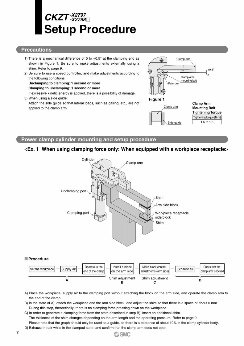
Procedure
Precautions
1) There is a mechanical difference of 0 to +0.5° at the clamping end as shown in Figure 1. Be sure to make adjustments externally using a shim. Refer to page 9.
2) Be sure to use a speed controller, and make adjustments according to the following conditions.Unclamping to clamping: 1 second or moreClamping to unclamping: 1 second or moreIf excessive kinetic energy is applied, there is a possibility of damage.
3) When using a side guide:Attach the side guide so that lateral loads, such as galling, etc., are not applied to the clamp arm.
A) Place the workpiece, supply air to the clamping port without attaching the block on the arm side, and operate the clamp arm to the end of the clamp.
B) In the state of A), attach the workpiece and the arm side block, and adjust the shim so that there is a space of about 0 mm.During this step, theoretically, there is no clamping force pressing down on the workpiece.
C) In order to generate a clamping force from the state described in step B), insert an additional shim.The thickness of the shim changes depending on the arm length and the operating pressure. Refer to page 9. Please note that the graph should only be used as a guide, as there is a tolerance of about 10% in the clamp cylinder body.
D) Exhaust the air while in the clamped state, and confirm that the clamp arm does not open.
<Ex. 1 When using clamping force only: When equipped with a workpiece receptacle>
Power clamp cylinder mounting and setup procedure
7
Cylinder
Shim w
Hard stop
Upper hard stop
Arm side block
Clamp arm
Distance to hard stop
Shim q
Clamping port
Unclamping port
Setup Procedure CKZT -X2797 -X2798
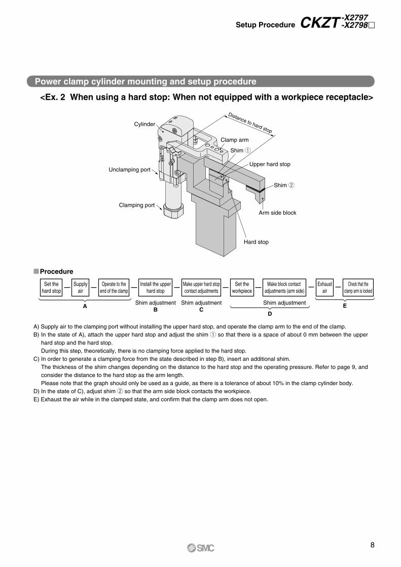
<Ex. 2 When using a hard stop: When not equipped with a workpiece receptacle>
A) Supply air to the clamping port without installing the upper hard stop, and operate the clamp arm to the end of the clamp.B) In the state of A), attach the upper hard stop and adjust the shim q so that there is a space of about 0 mm between the upper
hard stop and the hard stop.During this step, theoretically, there is no clamping force applied to the hard stop.
C) In order to generate a clamping force from the state described in step B), insert an additional shim.The thickness of the shim changes depending on the distance to the hard stop and the operating pressure. Refer to page 9, and consider the distance to the hard stop as the arm length.Please note that the graph should only be used as a guide, as there is a tolerance of about 10% in the clamp cylinder body.
D) In the state of C), adjust shim w so that the arm side block contacts the workpiece.E) Exhaust the air while in the clamped state, and confirm that the clamp arm does not open.
Procedure
Power clamp cylinder mounting and setup procedure
Supplyair
Set thehard stop
A
Operate to theend of the clamp
Shim adjustmentB
Install the upperhard stop
Shim adjustmentShim adjustmentC
Make upper hard stopcontact adjustments
Set theworkpiece
D
Make block contact adjustments (arm side)
Exhaustair
Check that theclamp arm is locked
E
8
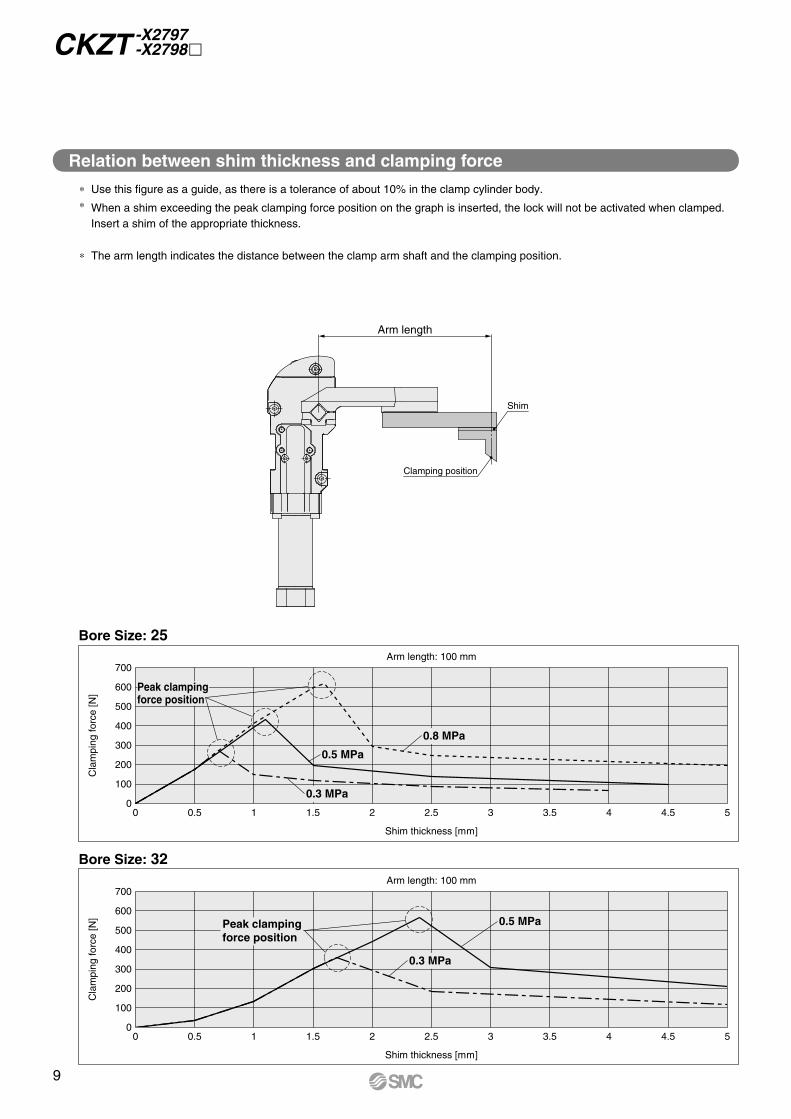
Shim thickness [mm]
Cla
mpi
ng fo
rce
[N]
0
100
200
300
400
500
600
700
0 0.5 1 1.5 2 2.5 3 3.5 4 4.5 5
Peak clampingforce position
Arm length: 100 mm
0.5 MPa0.5 MPa
0.3 MPa0.3 MPa
Arm length
Clamping position
Shim
Shim thickness [mm]
Cla
mpi
ng fo
rce
[N]
0
100
200
300
400
500
600
700
0 0.5 1 1.5 2 2.5 3 3.5 4 4.5 5
0.8 MPa0.8 MPa
0.5 MPa0.5 MPa
0.3 MPa0.3 MPa
Peak clampingforce position
Arm length: 100 mm
CKZT -X2797 -X2798
Bore Size: 32
Bore Size: 25
Relation between shim thickness and clamping force
∗ Use this figure as a guide, as there is a tolerance of about 10% in the clamp cylinder body.∗ When a shim exceeding the peak clamping force position on the graph is inserted, the lock will not be activated when clamped.
Insert a shim of the appropriate thickness.
∗ The arm length indicates the distance between the clamp arm shaft and the clamping position.
9
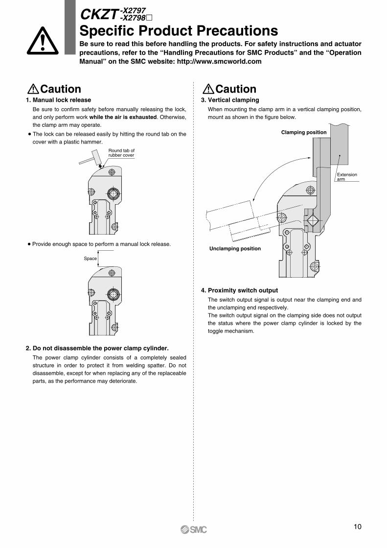
1. Manual lock releaseBe sure to confirm safety before manually releasing the lock, and only perform work while the air is exhausted. Otherwise, the clamp arm may operate.
The lock can be released easily by hitting the round tab on the cover with a plastic hammer.
Round tab ofrubber cover
Provide enough space to perform a manual lock release.
Space
2. Do not disassemble the power clamp cylinder.The power clamp cylinder consists of a completely sealed structure in order to protect it from welding spatter. Do not disassemble, except for when replacing any of the replaceable parts, as the performance may deteriorate.
Caution Caution3. Vertical clamping
When mounting the clamp arm in a vertical clamping position, mount as shown in the figure below.
Unclamping position
Extensionarm
Clamping position
4. Proximity switch outputThe switch output signal is output near the clamping end and the unclamping end respectively.The switch output signal on the clamping side does not output the status where the power clamp cylinder is locked by the toggle mechanism.
Be sure to read this before handling the products. For safety instructions and actuator precautions, refer to the “Handling Precautions for SMC Products” and the “Operation Manual” on the SMC website: http://www.smcworld.com
CKZT -X2797 -X2798m
Specific Product Precautions
10
Safety Instructions Be sure to read the “Handling Precautions for SMC Products” (M-E03-3) and “Operation Manual” before use.
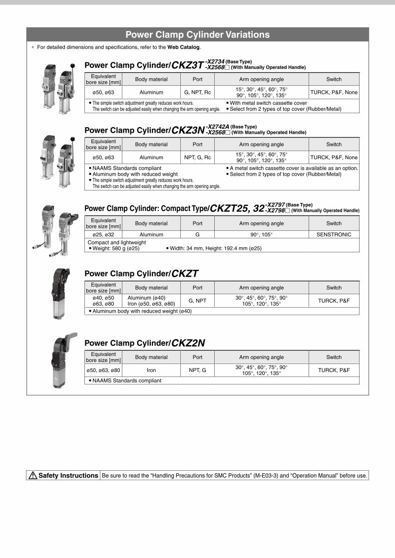
Power Clamp Cylinder Variations* For detailed dimensions and specifications, refer to the Web Catalog.
Equivalentbore size [mm] Body material Port Arm opening angle Switch
ø50, ø63 Aluminum G, NPT, Rc 15°, 30°, 45°, 60°, 75°90°, 105°, 120°, 135° TURCK, P&F, None
The simple switch adjustment greatly reduces work hours.The switch can be adjusted easily when changing the arm opening angle.
With metal switch cassette cover Select from 2 types of top cover (Rubber/Metal)
Equivalentbore size [mm] Body material Port Arm opening angle Switch
ø50, ø63 Aluminum NPT, G, Rc 15°, 30°, 45°, 60°, 75°90°, 105°, 120°, 135° TURCK, P&F, None
NAAMS Standards compliant Aluminum body with reduced weight The simple switch adjustment greatly reduces work hours.
The switch can be adjusted easily when changing the arm opening angle.
A metal switch cassette cover is available as an option. Select from 2 types of top cover (Rubber/Metal)
Equivalentbore size [mm] Body material Port Arm opening angle Switch
ø25, ø32 Aluminum G 90°, 105° SENSTRONIC
Compact and lightweight Weight: 580 g (ø25) Width: 34 mm, Height: 192.4 mm (ø25)
Power Clamp Cylinder/CKZTEquivalent
bore size [mm] Body material Port Arm opening angle Switch
ø40, ø50ø63, ø80
Aluminum (ø40)Iron (ø50, ø63, ø80) G, NPT 30°, 45°, 60°, 75°, 90°
105°, 120°, 135° TURCK, P&F
Aluminum body with reduced weight (ø40)
Power Clamp Cylinder/CKZ2NEquivalent
bore size [mm] Body material Port Arm opening angle Switch
ø50, ø63, ø80 Iron NPT, G 30°, 45°, 60°, 75°, 90°105°, 120°, 135° TURCK, P&F
NAAMS Standards compliant
Power Clamp Cylinder/CKZ3T -X2734 (Base Type)-X2568 (With Manually Operated Handle)
Power Clamp Cylinder/CKZ3N -X2742A (Base Type)-X2568 (With Manually Operated Handle)
Power Clamp Cylinder: Compact Type/CKZT25, 32-X2797 (Base Type)-X2798 (With Manually Operated Handle)