Embed Size (px)
Citation preview

WITNESS TEST PROCEDURETEMPLATE
National Grid Use Only:
Doc. # PR.756.A.12.16Publication Date: 12/6/16
Document Sponsor: Neil F. LaBrake,Retail Connections Policy & Standards
Next Scheduled Review: 8/1/17
Informative (*Customer to review then remove this page from submitted witness test procedure)
Customers seeking to interconnect a distributed generation (“DG”) facility to National Grid’s1 electric power system(“EPS”) must demonstrate that such facility has met all protective relaying requirements necessary to safely and reliablyinterconnect to the EPS (“Connection Requirements”). The Company has developed this template solely for the purposeof providing a more standardized format for customer documented witness testing procedures (“Procedures”) to assistthe Company’s review of such Procedures and the testing of the DG facility in accordance therewith.
This template contains only a sample of the minimum Connection Requirements for most DG facilities. There may beadditional or fewer requirements applicable to any specific facility. It is the customer’s sole obligation to determine theConnection Requirements applicable to the facility and to update this witness testing procedure template as necessary(including, without limitation, to the extent any Connection Requirement contained herein is incomplete, inaccurate, orsubsequently amended).
In general, the customer shall write the witness test procedure for each Connection Requirement using the followingformat:
Descriptive Test Title<Required Function to be Demonstrated><Detailed steps to prove the above statement><Witness Testing Sign off>
It is the customer’s responsibility to arrange the tests in this template in an order that is appropriate for the facility beingtested. The customer shall identify the devices to be operated for each test and any steps required to move from onetest condition to another. If the customer’s witness testing will take place over two or more days, the customer shallindicate in its Procedures the number of days of testing expected, and the tests expected to occur on each day.
To the extent the customer includes Procedures for the testing of functions that are not required to be witnessed by theCompany, the Company, in its discretion, may request that such functions be removed from the testing Procedures, ormay refrain from witnessing that portion of the Procedure. This shall not be construed to mean that the testing of suchfunctions is not required for the operation of the facility, and it shall be the customer’s obligation to perform the testingof such functions separate from the Company’s witness testing if necessary.
The customer must complete this document in sufficient detail, and provide applicable supporting documentation suchas project drawings, to identify the scope of work for each individual test necessary to demonstrate that the ConnectionRequirements have been met, including without limitation, the Company’s Electric Service Bulletin (ESB) 756 andInstitute of Electrical and Electronics Engineers (IEEE) 1547, as the same may be amended from time to time. TheCompany is relying upon the information provided by the customer herein, and the customer shall ensure that allinformation provided is true, complete and accurate.
Procedures must be approved by the Company in writing before the customer performs the witness testing for thefacility. The Company’s approval of the customer’s Procedures does not mean that the customer is authorized tointerconnect to the Company’s EPS.
It is the customer’s sole obligation to ensure that the facility meets all applicable federal, state, and local, codes, rules,regulations, and laws (collectively “Applicable Laws”). The Company’s approval of the Procedures does not mean, byimplication or otherwise, that the customer’s facility complies with the Connection Requirements or Applicable Laws.
By using this template (in whole or part) the customer acknowledges that he/she understands and agrees with thestatements contained in this section.
1 National Grid or the Company shall mean only Massachusetts Electric Company, The Narragansett Electric Company, or NiagaraMohawk Power Corporation, each d/b/a National Grid, depending on the location of the customer’s facility.
WITNESS TEST PROCEDURES
National Grid Project Tracking ID:
P a g e 1 o f 1 6 Revision #:_____ Date:_____
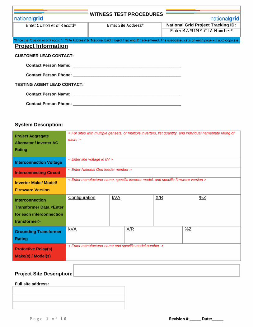
Project Information
CUSTOMER LEAD CONTACT:
Contact Person Name: _______________________________________________
Contact Person Phone: _______________________________________________
TESTING AGENT LEAD CONTACT:
Contact Person Name: _______________________________________________
Contact Person Phone: _______________________________________________
System Description:
Project Aggregate
Alternator / Inverter AC
Rating
< For sites with multiple gensets, or multiple inverters, list quantity, and individual nameplate rating of
each. >
Interconnection Voltage< Enter line voltage in kV >
Interconnecting Circuit< Enter National Grid feeder number >
Inverter Make/ Model/
Firmware Version
< Enter manufacturer name, specific inverter model, and specific firmware version >
Interconnection
Transformer Data <Enter
for each interconnection
transformer>
Configuration kVA X/R %Z
Grounding Transformer
Rating
kVA X/R %Z
Protective Relay(s)
Make(s) / Model(s)
< Enter manufacturer name and specific model number >
Project Site Description:
Full site address:
WITNESS TEST PROCEDURES
National Grid Project Tracking ID:
P a g e 2 o f 1 6 Revision #:_____ Date:_____
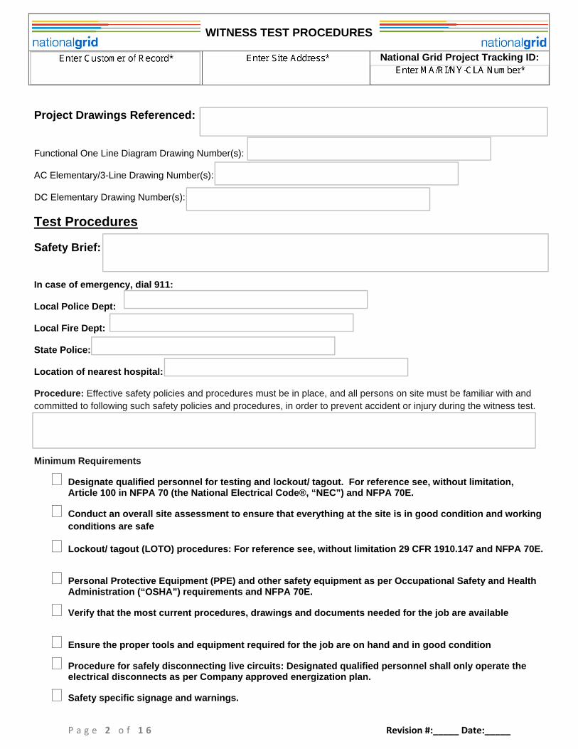
Project Drawings Referenced:
Functional One Line Diagram Drawing Number(s):
AC Elementary/3-Line Drawing Number(s):
DC Elementary Drawing Number(s):
Test Procedures
Safety Brief:
In case of emergency, dial 911:
Local Police Dept:
Local Fire Dept:
State Police:
Location of nearest hospital:
Procedure: Effective safety policies and procedures must be in place, and all persons on site must be familiar with and
committed to following such safety policies and procedures, in order to prevent accident or injury during the witness test.
Minimum Requirements
Designate qualified personnel for testing and lockout/ tagout. For reference see, without limitation,Article 100 in NFPA 70 (the National Electrical Code®, “NEC”) and NFPA 70E.
Conduct an overall site assessment to ensure that everything at the site is in good condition and working
conditions are safe
Lockout/ tagout (LOTO) procedures: For reference see, without limitation 29 CFR 1910.147 and NFPA 70E.
Personal Protective Equipment (PPE) and other safety equipment as per Occupational Safety and HealthAdministration (“OSHA”) requirements and NFPA 70E.
Verify that the most current procedures, drawings and documents needed for the job are available
Ensure the proper tools and equipment required for the job are on hand and in good condition
Procedure for safely disconnecting live circuits: Designated qualified personnel shall only operate theelectrical disconnects as per Company approved energization plan.
Safety specific signage and warnings.
WITNESS TEST PROCEDURES
National Grid Project Tracking ID:
P a g e 3 o f 1 6 Revision #:_____ Date:_____
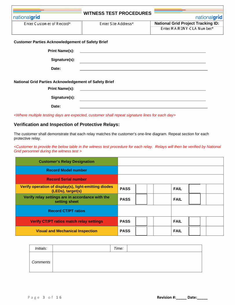
Customer Parties Acknowledgement of Safety Brief
Print Name(s):
Signature(s):
Date:
National Grid Parties Acknowledgement of Safety Brief
Print Name(s):
Signature(s):
Date:
<Where multiple testing days are expected, customer shall repeat signature lines for each day>
Verification and Inspection of Protective Relays:
The customer shall demonstrate that each relay matches the customer’s one-line diagram. Repeat section for eachprotective relay.
<Customer to provide the below table in the witness test procedure for each relay. Relays will then be verified by NationalGrid personnel during the witness test >
Customer’s Relay Designation
Record Model number
Record Serial number
Verify operation of display(s), light-emitting diodes(LEDs), target(s)
PASS FAIL
Verify relay settings are in accordance with thesetting sheet
PASS FAIL
Record CT/PT ratios
Verify CT/PT ratios match relay settings PASS FAIL
Visual and Mechanical Inspection PASS FAIL
Initials: Time:
Comments
WITNESS TEST PROCEDURES
National Grid Project Tracking ID:
P a g e 4 o f 1 6 Revision #:_____ Date:_____
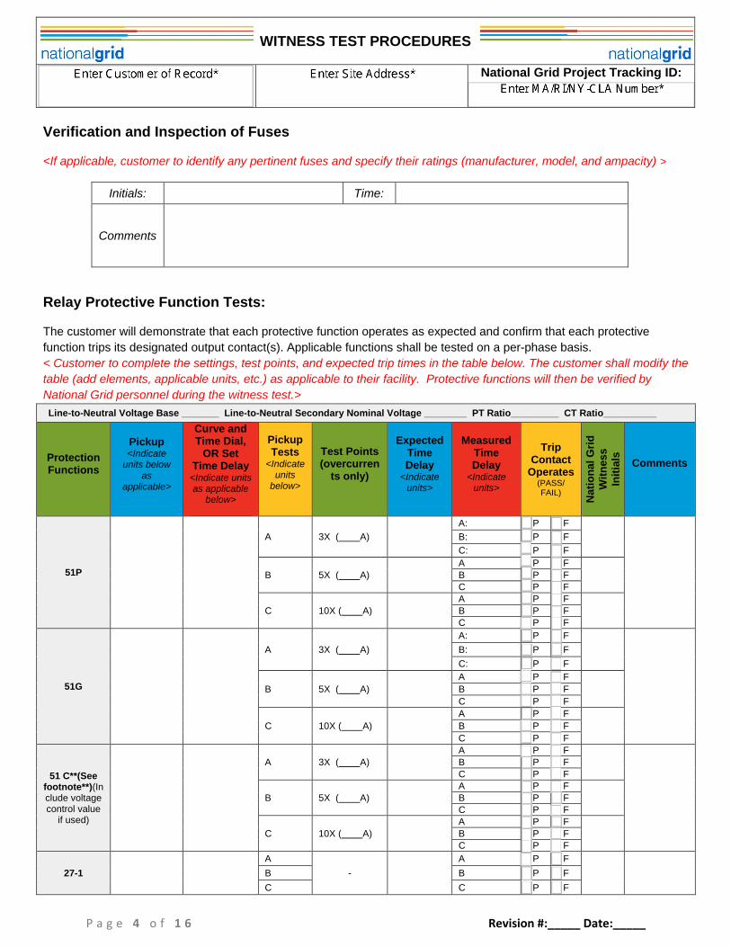
Verification and Inspection of Fuses
<If applicable, customer to identify any pertinent fuses and specify their ratings (manufacturer, model, and ampacity) >
Initials: Time:
Comments
Relay Protective Function Tests:
The customer will demonstrate that each protective function operates as expected and confirm that each protective
function trips its designated output contact(s). Applicable functions shall be tested on a per-phase basis.
< Customer to complete the settings, test points, and expected trip times in the table below. The customer shall modify the
table (add elements, applicable units, etc.) as applicable to their facility. Protective functions will then be verified by
National Grid personnel during the witness test.>
Line-to-Neutral Voltage Base _______ Line-to-Neutral Secondary Nominal Voltage ________ PT Ratio_________ CT Ratio__________
ProtectionFunctions
Pickup<Indicate
units belowas
applicable>
Curve andTime Dial,
OR SetTime Delay<Indicate unitsas applicable
below>
PickupTests
<Indicateunits
below>
Test Points(overcurren
ts only)
ExpectedTimeDelay
<Indicateunits>
MeasuredTimeDelay
<Indicateunits>
TripContact
Operates(PASS/FAIL)
Nati
on
al
Gri
dW
itn
ess
Init
ials
Comments
51P
A 3X ( A)
A: P F
B: P F
C: P F
B 5X ( A)A P FB P FC P F
C 10X ( A)A P FB P FC P F
51G
A 3X ( A)
A: P F
B: P F
C: P F
B 5X ( A)
A P F
B P F
C P F
C 10X ( A)
A P F
B P F
C P F
51 C**(Seefootnote**)(Include voltagecontrol value
if used)
A 3X ( A)A P FB P FC P F
B 5X ( A)A P FB P FC P F
C 10X ( A)A P FB P FC P F
27-1
A
-
A P F
B B P F
C C P F
WITNESS TEST PROCEDURES
National Grid Project Tracking ID:
P a g e 5 o f 1 6 Revision #:_____ Date:_____
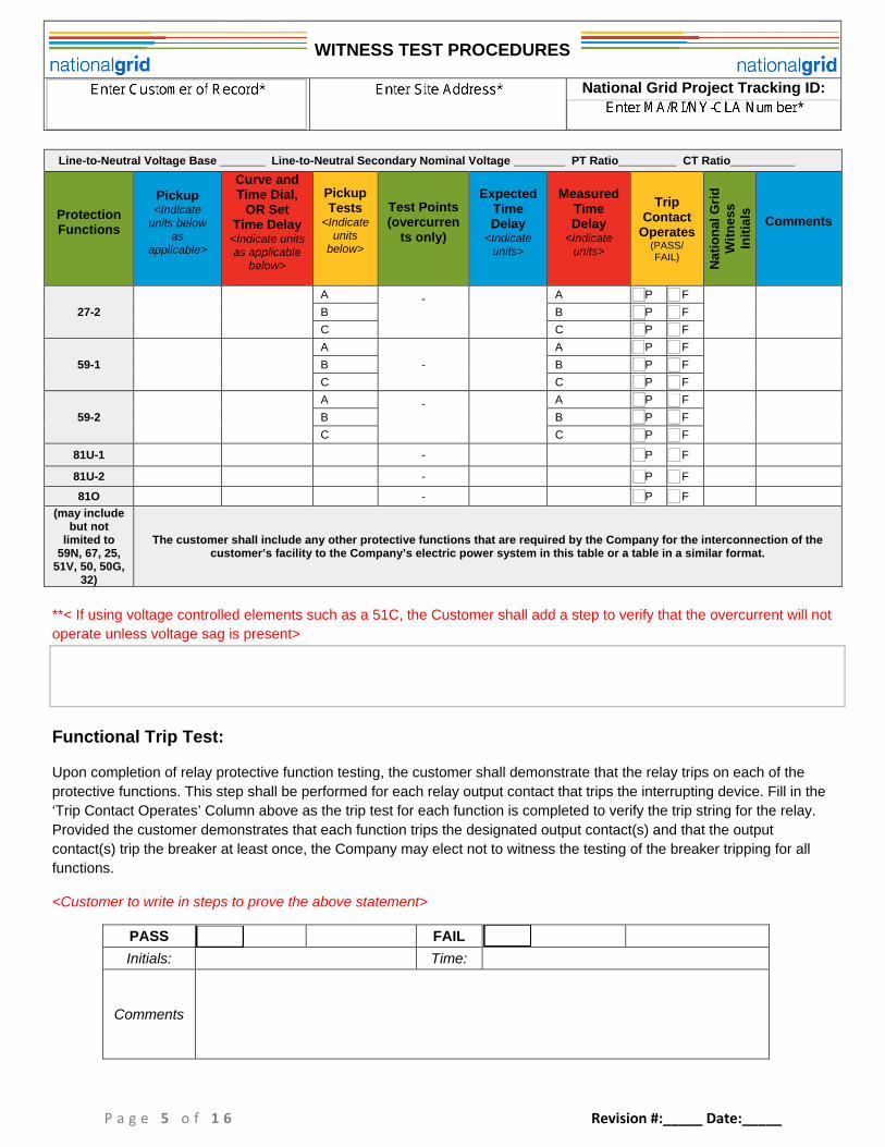
Line-to-Neutral Voltage Base _______ Line-to-Neutral Secondary Nominal Voltage ________ PT Ratio_________ CT Ratio__________
ProtectionFunctions
Pickup<Indicate
units belowas
applicable>
Curve andTime Dial,
OR SetTime Delay<Indicate unitsas applicable
below>
PickupTests
<Indicateunits
below>
Test Points(overcurren
ts only)
ExpectedTimeDelay
<Indicateunits>
MeasuredTimeDelay
<Indicateunits>
TripContact
Operates(PASS/FAIL)
Nati
on
al
Gri
dW
itn
ess
Init
ials
Comments
27-2
A - A P F
B B P F
C C P F
59-1
A
-
A P F
B B P F
C C P F
59-2
A - A P F
B B P F
C C P F
81U-1 - P F
81U-2 - P F
81O - P F
(may includebut not
limited to59N, 67, 25,
51V, 50, 50G,32)
The customer shall include any other protective functions that are required by the Company for the interconnection of thecustomer’s facility to the Company’s electric power system in this table or a table in a similar format.
**< If using voltage controlled elements such as a 51C, the Customer shall add a step to verify that the overcurrent will not
operate unless voltage sag is present>
Functional Trip Test:
Upon completion of relay protective function testing, the customer shall demonstrate that the relay trips on each of the
protective functions. This step shall be performed for each relay output contact that trips the interrupting device. Fill in the
‘Trip Contact Operates’ Column above as the trip test for each function is completed to verify the trip string for the relay.
Provided the customer demonstrates that each function trips the designated output contact(s) and that the output
contact(s) trip the breaker at least once, the Company may elect not to witness the testing of the breaker tripping for all
functions.
<Customer to write in steps to prove the above statement>
PASS FAIL
Initials: Time:
Comments

WITNESS TEST PROCEDURES
National Grid Project Tracking ID:
P a g e 6 o f 1 6 Revision #:_____ Date:_____
Block Close Test (IEEE1547 section 4.2.6):
The customer shall demonstrate that:
the intertie device cannot be closed back in during the five minute measurement of acceptable voltage andfrequency as defined in IEEE1547-2003 section 4.2.6 (voltage shall be within ANSI range B and frequency59.3Hz and 60.5Hz);
all forms of closing the customer’s recloser / breaker (electrical / mechanical, manual / automatic) are blockedduring the block close. Ensure that the interrupting device cannot be closed manually during this time or ifacceptable utility voltage and frequency are not present; and
the timer restarts if voltage and frequency fall outside of this window.
<Customer to write in steps to prove the above statements>
PASS FAIL
Initials: Time:
Comments
Trip on Relay Failure:
The customer shall simulate a relay alarm and demonstrate that the relay trips the interrupting device upon relay alarmcontact assertion. In case of relay device failure with no relay redundancy, the interrupting device is required to trip within2 seconds. In cases with full relay redundancy, the customer shall have the failure of both relays at the same time trip theinterrupting device. Also demonstrate that the interrupting device cannot be closed back in when the relay has failed or isotherwise out of service. The customer shall specify the test switches to be opened for this step.
<Customer to write in steps to prove the above statements>
PASS FAIL
Initials: Time:
Comments

WITNESS TEST PROCEDURES
National Grid Project Tracking ID:
P a g e 7 o f 1 6 Revision #:_____ Date:_____
Trip on Sudden Loss of Power Supply:
The customer shall simulate a loss of power supply and demonstrate that the relay trips the interrupting device in a fail-safe manner. In case of relay device failure with no relay redundancy, the interrupting device is required to trip within 2seconds. In cases with full relay redundancy, the customer shall have the failure of both relays at the same time trip theinterrupting device. Also demonstrate that the interrupting device cannot be closed back in when the relay has failed or isotherwise out of service. The customer shall specify the test switches to be opened for this step.
<Customer to write in steps to prove the above statements>
Trip on Relay Power Supply System Trouble:
The customer shall simulate DC system trouble and confirm that the monitoring relay trips the interrupting device upon DCvoltage falling out of normal operating range. ( ___%)
<Customer to write in steps to prove the above statement>
DG Operational Only if Ground Source in Service:
For DG that requires a grounding transformer to interconnect, the Customer shall demonstrate that the inverters or otherDG cannot operate if the grounding transformer (if applicable) is not closed in.
<Customer to write in steps to prove the above statement>
PASS FAIL
Initials: Time:
Comments
PASS FAIL
Initials: Time:
Comments
PASS FAIL
Initials: Time:
Comments

WITNESS TEST PROCEDURES
National Grid Project Tracking ID:
P a g e 8 o f 1 6 Revision #:_____ Date:_____
In-Service Check:
The customer shall demonstrate that the primary current and voltage magnitude and angle readings match between thecustomer relay and an independent metering source.
<Customer to write in steps to prove the above statement, which may include, without limitation, the minimumrequirements below>
Identify the devices used in the tables below. Verify and record currents and voltages of all phases. Compare amps/voltages to a National Grid device (or other independent metering source proposed
by the customer and accepted by National Grid). This is most often National Grid’s pole-top recloser. If possible, provide screenshots of the voltage and current phasors from each device *Indicate whether the device readings match in both magnitude and phase angle, if applicable.
QuantityCustomer Relay
VoltageIndependent Metering Source Voltage
(if a National Grid device is used, to becompleted by National Grid)
Match(Y/N)*
Mag. Angle Mag. Angle
VA
VB
VC
Quantity Customer RelayCurrent
Independent Metering Source Current(if a National Grid device is used, to be
completed by National Grid)
Match(Y/N)*
Mag. Angle Mag. Angle
IA
IB
IC
IN
PASS FAIL
Initials: Time:
Comments

WITNESS TEST PROCEDURES
National Grid Project Tracking ID:
P a g e 9 o f 1 6 Revision #:_____ Date:_____
Other Tests As Needed:
It is the customer’s responsibility to write the test procedures to prove to the Company’s satisfaction that the facility hasmet all protective relaying requirements necessary to safely and reliably interconnect to the Company’s electric powersystem.
<Customer to write in any additional witness test procedures necessary to prove all connection requirements have beenmet>
Other tests that may be required include, but are not limited to:
Interlocks to keep a DG off an adjacent feeder (commonly applicable to critical facilities with dual feeders). Interlocks to keep the DG disconnected from the utility line while intended to be an islanded facility. Synchronism check (25 function) to ensure the facility is synchronized to the grid before connecting. For facilities seeking to island their load behind an intertie breaker: When the generator breaker is closed, verify that the
intertie breaker cannot close back in without the utility voltage being within the acceptable range in IEEE1547-2003 section4.2.6 for 5 minutes, and synch check being performed. If the intertie breaker is already closed, test that the generator breakercannot close if 5 minutes or more of acceptable utility haven’t been detected (note that the generator breaker may close if theintertie breaker is open for purposeful islanding).
As Left Settings:
Retrieve as-left settings from the relay and provide to National Grid personnel.
Test Performed By:
Test Witnessed By:
Date: _________________
Customer representative:__________________________________
National Grid representative:_______________________________
YES NO
Initials: Filename:
Comments
WITNESS TEST PROCEDURES
National Grid Project Tracking ID:
P a g e 1 0 o f 1 6 Revision #:_____ Date:_____
Direct Transfer Trip (“DTT”) Tests (applicable only to facilities with DTT):
If the customer has been required to install DTT, perform the following DTT tests. The customer shall identify all test
switches to be used to perform the following DTT tests. At minimum the customer shall state the relays to be tested, the
test switches to be operated and the expected results including output contacts to be asserted.
DTT Communication Test
The customer shall demonstrate that there is communication between the signal transmitter and receiver. National Grid
personnel to record signal strengths between the two devices.
<Customer to write in steps to prove the above statement>
DTT Trip Test
The customer shall demonstrate that the DTT interrupting device trips upon receiving a trip signal. The customer shall
also demonstrate that trips on the relay open the interrupting device.
<Customer to write in steps to prove the above statements>
DTT Block Close Test
The customer shall demonstrate that the DTT interrupting device cannot be closed when DTT trip is asserted.
<Customer to write in steps to prove the above statement>
PASS FAIL
Initials: Time:
Comments
PASS FAIL
Initials: Time:
Comments
PASS FAIL
Initials: Time:
Comments
WITNESS TEST PROCEDURES
National Grid Project Tracking ID:
P a g e 1 1 o f 1 6 Revision #:_____ Date:_____
DTT Loss of Communication Trip Test
The customer shall demonstrate that the DTT interrupting device trips upon the loss of communication.
<Customer to write in steps to prove the above statement>
DTT Block Close Test – Loss of Communication
The customer shall demonstrate that the DTT interrupting device cannot be closed when DTT Communication is notavailable.
<Customer to write in steps to prove the above statement>
DTT Loss of Relay Power Trip Test
The customer shall demonstrate that the DTT interrupting device trips upon relay failure and poor DC control power.
<Customer to write in steps to prove the above statement>
PASS FAIL
Initials: Time:
Comments
DTT Loss of Relay Power Block Close Test
The customer shall demonstrate that the DTT interrupting device cannot be closed back in if the relay is out of service.
<Customer to write in steps to prove the above statement>
PASS FAIL
Initials: Time:
Comments
PASS FAIL
Initials: Time:
Comments
PASS FAIL
Initials: Time:
Comments
WITNESS TEST PROCEDURES
National Grid Project Tracking ID:
P a g e 1 2 o f 1 6 Revision #:_____ Date:_____
DTT Status Bit Test
The customer shall verify that the status breaker bits have been transmitted and received.
<Customer to write in steps to prove the above statement>
DTT As Left Settings
Retrieve as-left settings from the DTT relay(s) and provide to National Grid personnel.
Test Performed By:
Test Witnessed By:
Date: ________
Customer representative:__________________________________
National Grid representative:_______________________________
PASS FAIL
Initials: Time:
Comments
YES NO
Initials: Filename:
Comments

WITNESS TEST PROCEDURES
National Grid Project Tracking ID:
P a g e 1 3 o f 1 6 Revision #:_____ Date:_____
Record and Verify that Inverter/Generator Controller Under/Over Voltage and FrequencySettings Match the Approved Settings:
<The customer must complete the proposed settings prior to witness testing. As-left settings for each invertershall be recorded on the day of testing either in the table below or, in cases where the inverter does not displaysettings, a factory test sheet can be provided and attached. Record or provide the serial number of eachinverter/generator.>
Functions ProposedPickup
<IndicateUnits>
ProposedTime Delay
<IndicateUnits>
As-LeftPickup
<IndicateUnits>
As-Left TimeDelay
<IndicateUnits>
27-1
27-2
59-1
59-2
81U-1
81U-2
81O
59 (Self-ProtectiveOvervoltage)
Firmware Version
Inverter Make/Model/SerialNumber
Initials: Time:
Comments

WITNESS TEST PROCEDURES
National Grid Project Tracking ID:
P a g e 1 4 o f 1 6 Revision #:_____ Date:_____
Two Second Shutdown Test:
The customer shall demonstrate that when upstream breaker / disconnect switch is open the inverter/generator
shuts down within 2 seconds.
<Customer to write in steps to prove the above statement>
Inverter/Generator Five Minute Reconnect Test (IEEE1547-2003 4.2.6):
The customer shall demonstrate that when the breaker / disconnect switch is closed back in that the inverter/generator
does not start for a minimum of 5 minutes. (For UL1741 certified generation only).
<Customer to write in steps to prove the above statement>
Test Performed By:
Test Witnessed By:
Date: _____________
Customer representative:__________________________________
National Grid representative:_______________________________
<If the customer’s witness testing will take place over two or more days, the customer shall indicate in its testing
procedures the number of days of testing expected, and the tests expected to occur on each day.>
PASS FAIL
Initials: Time:
Comments
PASS FAIL
Initials: Time:
Comments
WITNESS TEST PROCEDURES
National Grid Project Tracking ID:
P a g e 1 5 o f 1 6 Revision #:_____ Date:_____
ONE-LINE
DIAGRAMAND
OTHER REQUIRED DRAWINGS