Embed Size (px)
Citation preview

1
Infrared Data Association
LAN Access Extensions for LinkManagement Protocol
IrLAN
Version 1.0
July 18, 1997
Extended Systems Incorporated
Hewlett-Packard Corporation
Microsoft Corporation

2
AuthorsDan Axtman (Extended Systems Incorporated),Aaron Ogus (Microsoft Corporation), andJohn Reilly (Hewlett-Packard Corporation)

3
TABLE OF CONTENTS
Authors ...............................................................................................................................................................................2TABLE OF CONTENTS ...................................................................................................................................................3Introduction .......................................................................................................................................................................4Design Goals ......................................................................................................................................................................4References ..........................................................................................................................................................................4Definition of Terms ...........................................................................................................................................................5Overview.............................................................................................................................................................................7Access Methods ...............................................................................................................................................................7
Access Point Mode......................................................................................................................................................7Peer-to-Peer Mode........................................................................................................................................................9Hosted Mode...............................................................................................................................................................10
IrLAN IAS Object Specification....................................................................................................................................11TinyTP Considerations ..................................................................................................................................................11
Maximum Assembled Frame Size..............................................................................................................................11Flow Control................................................................................................................................................................11
Frame Formats..................................................................................................................................................................12Data-Channel Frame Formats ....................................................................................................................................12Control-Channel Frame Formats ...............................................................................................................................13
Command Packet Structure ...................................................................................................................................13Response Packet Structure ...................................................................................................................................14Packet Parameter List Format................................................................................................................................14
IrLAN Command Descriptions......................................................................................................................................160 - Get Provider Information ......................................................................................................................................171 - Get Media Characteristics ....................................................................................................................................192 - Open Data Channel...............................................................................................................................................213 - Close Data Channel...............................................................................................................................................234 - Reconnect Data Channel......................................................................................................................................255 - Filter Configuration ...............................................................................................................................................27
State Machines ................................................................................................................................................................37Client State Chart ........................................................................................................................................................37
Client State Definitions..........................................................................................................................................38Client Event Descriptions .....................................................................................................................................39Client Action Descriptions ...................................................................................................................................40
Provider State Chart....................................................................................................................................................41Provider State Definitions.....................................................................................................................................42Provider Event Descriptions.................................................................................................................................42Provider Action Descriptions...............................................................................................................................42
Peer-to-Peer Mode Considerations ..............................................................................................................................43Data-Channel Frame Formats ....................................................................................................................................43MacAddress Generation............................................................................................................................................43

4
IntroductionThe creation of the IrDA protocols and their broad industry support has led to IrDA-compliant infraredports becoming common on laptop computers. With the IrDA approval of the higher media speeds of 1.15and 4 megabits per second (Mbps), the infrared link is becoming fast enough to support a network interface.
This document describes a protocol, conforming to the IrDA specifications, that has these features:
• Enables a computer with an IrDA adapter to attach to a local area network (LAN) through an accesspoint device that acts as the network adapter for the computer.
• Enables two computers with IrDA adapters to communicate as though they were attached through aLAN.
• Enables a computer with an IrDA-compliant adapter to be attached to a LAN through a secondcomputer that is already attached to the LAN (the second computer must also have an IrDA-compliantadapter).
The proposed protocol, the infrared LAN (IrLAN) protocol, should allow for interoperability of all devicessupporting the protocol.
Design GoalsThe IrLAN protocol has these design goals:
• The IrLAN protocol deals with the issues associated with running legacy networking protocols over aninfrared link. It supports three different operating modes that represent the possible configurationsbetween infrared devices and between infrared devices and an attached network.
Mode DescriptionAccess point An infrared device provides access to a LAN through the device.Peer-to-peer Two or more computers with infrared support can communicate as if they were
attached through a network.Hosted Two or more computers can communicate with a host computer and each other as if
they were all attached through a network. In addition, a physical network attached tothe host is accessible to all of the computers.
• From a client operating-system perspective, the IrLAN protocol must be implemented completely as aset of network media-level drivers. No modification of the existing network protocols should benecessary.
• The IrLAN protocol must not impose excessive processing constraints on access point devices, whichmay be implemented with slower processors than typically found in modern computers.
ReferencesThe IrLAN protocol is based on the following IrDA-approved specifications:
• Infrared Data Association Serial Infrared Link Access Protocol (IrLaP), available from the IrDA.• Infrared Data Association Link Management Protocol (IrLMP) , available from the IrDA.• Infrared Data Association ‘TinyTP’: A Flow-Control Mechanism for use with IrLMP, available from
the IrDA.
Requests for publications, membership applications, or other information should be addressed to: InfraredData Association, P.O. Box 3883, Walnut Creek, California, U.S.A. 94598; sent by e-mail to:[email protected]; phoned to: John LaRoche at (510) 943-6546; or faxed to: (510) 934-5241.

5
Definition of Terms The following technical terms are used in this document.
Control channelAn IrLMP communication channel used by the client and offered by the provider to allow for the setupand configuration of a data channel.
Data channelAn IrLMP communication channel used by the client and provider to exchange LAN-formatted packets.
Frame (or media frame)A block of data on the media. A packet may consist of multiple media frames.
IAS (information access service)Part of the IrDA protocol suite, the IAS is a standard IrLMP client that implements a local store ofconfiguration information. Information is stored under a primary key called the class and under subkeysin each class called attributes. The class may only contain subkeys, each of which is unique in the class,and each subkey may contain a corresponding value, which may be a string or an integer. Multipleobjects of the same class are allowed, and each object in the IAS may be read by a remote stationsupporting the IAS protocol.
IrLAN client (or client)The station in an IrLAN link that is using the IrLAN services of a provider to set up an IrLAN link. Theclient is the active component in the IrLAN protocol; it issues requests to the IrLAN provider toestablish a data link and to configure the link.
IrLAP (Infrared Link Access Protocol)A protocol, based on the HDLC protocol, designed to control an infrared link. IrLAP provides fordiscovery of devices, their connection over an infrared link, and reliable data delivery between devices.
IrLMP (Infrared Link Management Protocol)A multiplexing protocol designed to run on top of IrLAP. IrLMP is multipoint-capable even thoughIrLAP is not. When IrLAP becomes multipoint-capable, multiple machines will be able to communicateconcurrently over an infrared link.
Infrared LAN access point deviceA network adapter with an infrared link to the LAN client. Conceptually, the infrared link is the bus thatthe LAN card resides on.
LANA local area network.
LSAP (logical service access point)A unique 1-byte identifier used by IrLMP to multiplex and demultiplex packets sent using IrLAP. Clientsof IrLMP logically open an LSAP and then attach it to a remote node, or receive attachment from aremote node. Clients typically advertise their LSAP to other clients by writing entries in the local IAS.
NIC (network interface controller)A piece of hardware designed to transmit and receive packets on a LAN network.

6
PacketA block of data that is transmitted or received over the media. The media may break a packet down intoseveral media frames to deliver it.
Primary stationA term used in IrLAP to specify the station that is controlling the infrared link. The other side of the linkis where the secondary station resides (or secondary stations reside). No secondary station can transmitwithout receiving permission from the primary station.
IrLAN Provider (provider)The station in an IrLAN link that is providing the IrLAN protocol interface.
Secondary stationA term used in IrLAP to specify a station that is controlled by the primary station. The secondary stationcan send when it receives permission from the primary station.
TinyTPA lightweight protocol, supporting flow control and segmentation and reassembly, that is designed foruse over an IrLMP connection. The full TinyTP specification is available in the publication InfraredData Association ‘TinyTP’: A Flow-Control Mechanism for use with IrLMP, available from the IrDA(for more information, see “References” earlier in this document).
Window sizeOne of the parameters negotiated between the two infrared nodes as part of establishing an IrLAPconnection. The window size specifies the number of consecutive IrLAP frames that a node can transmitbefore it must allow the other node an opportunity to transmit. The maximum IrLAP window size is sevenframes.

7
OverviewThe IrLAN protocol is a “sided” protocol that defines a two-channel interface between a protocol client anda protocol server. An IrLAN provider is passive. It is up to the IrLAN client to discover and then attach tothe provider and open up a data channel over which LAN packets can be transmitted and received. In IrLANpeer-to-peer mode (which is also described in “Access Methods”), each station has both an IrLan client andprovider. There is a race to determine which node will open the Data channel. This race condition is resolvedby the protocol in State Machines described later in this document.
The client begins setting up the connection by reading an object’s information in the provider’s IAS. Theobject specifies an IrLMP LSAP for the “control channel.” The client connects to the control channel anduses the control channel to negotiate the characteristics of a data channel. Once the data channel has beennegotiated, it is opened and then configured. All configuration is handled through the control channel. Thedata channel is used solely for the transmission and reception of packets formatted for the LAN. The IrLANprotocol defines a graceful close, but it is seldom used because it would require user intervention to initiatea disconnect. Typically, the connection will close down “ungracefully” through an IrLAP connection time-out.
Both the control and data channels use the TinyTP protocol for segmentation and reassembly of packetsand for flow control.
Access MethodsThe IrLAN protocol is intended to support these modes of operation:• Access point• Peer-to-peer• Hosted
Access Point ModeAn access point device is hardware supporting both a LAN network interface controller (NIC) and aninfrared transceiver. For communication over the infrared link, the access point device runs a protocol stackthat conforms to the IrDA standards and runs the IrLAN protocol over the IrDA stack. The access pointdevice implements a network adapter for the client using infrared as the bus for accessing the adapter.

8
The following illustration shows the access point mode of operation.
Filtering information is passed from the client to the access point device to minimize the transmission ofunwanted traffic over the infrared link. In this case, the access point device assigns a unique UNICASTaddress to each client connecting to the device.
It is quite reasonable to expect future implementation of access point devices to support multiple concurrentclients connecting to the LAN. In this case, each client would be assigned a unique LAN address, and theaccess point device would likely use a NIC supporting multiple concurrent UNICAST addresses.
LAN Bridge
IrLANProvider
IrLMP/TinyTPControlLSAP’s
Data LSAP’sNIC Network
ControlLSAP
Data LSAPIrLMP/TinyTP
IrLANClient
ClientO S
ControlLSAP
Data LSAPIrLMP/TinyTP
IrLANClient
ClientO S

9
Peer-to-Peer ModeThe IrLAN protocol peer-to-peer mode allows nodes running network operating systems that are peer-to-peer capable to create ad-hoc networks. The following illustration shows the peer-to-peer mode.
In peer-to-peer mode, there is no physical connection to a wired LAN. Filtering information can still be sentto the provider during the connection setup process. The filters allow the provider to lower traffic whenboth peers are not running the exact same protocol suites. Also, the filters can lower traffic in the case ofpoint-to-multipoint traffic.
In peer-to-peer mode, each peer must provide a Server Control LSAP in addition to its Client Control LSAPand Data LSAP. Each Client Control LSAP connects to its peer’s Server Control LSAP. This allows eachnode to establish and control its peer’s Data LSAP using the command set described herein. The IrLANcontrol protocol is used to arbitrate which peer initiates the data channel connection as described in thesection State Machines later in this document.
IrLANProvider
ClientO S
IrLANClient
IrLMP/TinyTPProvider ControlLSAP
Client ControlLSAPData
LSAP
ClientO S
IrLANClient
IrLMP/TinyTP
Provider ControlLSAP
Client ControlLSAP
DataLSAP
IrLANProvider

10
Hosted ModeIn hosted mode, the provider has a wired network connection, but has multiple nodes attempting tocommunicate through the wired connection. The following illustration shows hosted mode.
Unlike access point mode, both the host machine and the client(s) share the same NIC address in host mode.To make host mode work, the host must run special bridging and routing software that will handle theproper routing of packets. The algorithms used in this mode are highly protocol-dependent.

11
IrLAN IAS Object SpecificationWhen a client connects to a provider, it looks in the provider’s IAS for the object with the “IrLAN” class.The client reads the following attribute information for the IrLAN object to determine which LSAP theIrLAN control channel resides on.
IrDA:TinyTP:LsapSel:<LSAP>
For compatibility with Plug-n-Play operating systems, peer nodes, access points and hosted mode hostsmust advertise the LAN and PNP hint bits in the discovery process. Access points should report PnP ID*PNP8294 in their PnP IAS entry. Peer nodes should report PnP ID *PNP8389 in their PnP IAS entry.
TinyTP ConsiderationsIn the IrLAN protocol, both the control and data channels use the TinyTP protocol for segmentation andreassembly of packets and for flow control. The use of TinyTP involves these elements:
• Maximum assembled frame size• Flow control
Maximum Assembled Frame SizeTinyTP allows for the fragmentation and reassembly of packets, which may span several IrLMP frames.During the setup of the TinyTP connection, a maximum assembled frame size is negotiated between the twosides.
The IrLAN protocol currently defines support for access to the 802.3 (Ethernet) and 802.5 (token-ring)LANs. (In the future, this protocol may be modified to support additional media types.) The assembledTinyTP frame should be large enough to support the maximum frame size for the media.
• For 802.3 (Ethernet), the assembled TinyTP frame size is 1,518 bytes. • For 802.5 (token ring), the assembled TinyTP frame size is 65,535 bytes. Because token ring permits a
smaller upper bound on the frame size, depending on the adapter technology in use, a 2,045-byteassembled frame size is acceptable for 802.5 support. A smart token-ring IrLAN implementation willscale the media frame size to fit well in an integer number of TinyTP frames, which depends on thenegotiated frame size. Examples of such scaling are shown in the following table.
TinyTP Frame Size Media Frame Size2,048 2,0451,024 2,042 512 2,036
Flow ControlTinyTP specifies a flow control mechanism based on extended credit; that is, during the setup of a TinyTPconnection, each side informs the other of a number of outstanding “credits,” where each credit represents aTinyTP packet that may be sent to the side extending the credit. Each time a packet is sent, the sending sideassumes that the receiving side has one less resource available for receiving packets. If the sending sidereaches the point where it determines the receiving side has no resources left because all credits have beenconsumed, it will stop transmitting until more credit is extended. The receiving side will extend more credit asresources are freed up on the receiving side.

12
When this flow mechanism operates in conjunction with IrLAP, it can lead to under-utilization of the link.This typically happens when the credit extended by a receiver is smaller than the window size negotiated byIrLAP. This results in the send window not being filled, and the link turns around as a consequence moreoften than it needs to. If at all possible, the receiver should extend at least enough credit so that thetransmitter can always fill an IrLAP window. The current maximum IrLAP window size is seven frames.Because a frame may not hold an entire packet, this is the actual formula for the minimum credit that shouldbe extended for optimum throughput:
CreditIrLapWindowSize
IrLapFrames TinyTpPacket=
/
Noninteger credit values derived from the formula should be rounded up to the next highest integer value.Examples of values derived from the formula are shown in the following table.
WindowSize Frames/Packet Recommended Credit7 1 77 2 4
Frame FormatsThe IrLAN protocol defines the commands used on the control channel as well as the format of data on thedata channel. These formats are defined above TinyTP; that is, TinyTP segmentation and reassembly andflow control is assumed to be handled by the TinyTP interface. The definitions in the following sections arefor the assembled TinyTP frames.
Data-Channel Frame FormatsFrames on the IrLAN data channel are formatted the same as for their respective media.
For 802.3 (Ethernet), the format is the same as would be transmitted at the software level for an 802.3 packet.The IrLAN data-channel frame does not contain the 802.3 FCS. This is the IrLAN data channel packet format(the numbers in the square brackets are the number of bytes in each part of the packet):
Destination Address [6] Source Address [6] Length or Frame Type [2] Information[0..1500]
For 802.5 (token ring), this is the IrLAN data channel packet format.
AccessControl[1]
FrameControl [1]
DestinationAddress[6]
SourceAddress [6]
RoutingControl[0..2]
RoutingInformation[0..16]
Information
These are the same formats typically used by network protocols when talking to network drivers. Usually,the IrLAN driver will only have to reformat the descriptors for the packets for transmission on the infraredmedia. The driver should not have to change any of the packets contents in either the peer-to-peer or accesspoint modes. In the hosted mode, some protocol specific transformations may have to be made.
Once the data channel is established, it is treated as the send and receive path for all frames on the emulatedLAN media. All packets sent from a node are transmitted on this channel, and all packets being received willcome from this channel.

13
Control-Channel Frame FormatsThe control channel is used to perform these tasks:
• Set up a data channel connection.• Set up configuration parameters for the data channel connection.
The control channel uses TinyTP as a flow control and segmentation and reassembly protocol. The clientand provider must both support a minimum 1,024-byte assembled frame size on the control channel. If aclient must send a command that exceeds 1,024 bytes, which is highly unlikely, it must send a sequence ofsmaller commands of the same type that accomplish the same purpose.
A command/response protocol is used on the control channel. Currently, only client-initiatedcommand/response pairs are defined. In the future, there may be a requirement for unsolicited responsesfrom the provider to the client, but these requirements have not been defined. If an unsolicited response isreceived from the provider, the client should check the result code field, which is the first byte of theresponse. If the result code field is not 0xFF, indicating a valid unsolicited response, the link should bedropped.
During a session, the client issues a sequence of request packets, each of which is immediately followed bya response from the provider. The format of the command packets and response packets are defined in thefollowing sections.
Command Packet StructureEach request consists of a command code, a count of parameters, and a parameter list for the command.
Command Code[1] Parameter Count[1] Parameter List[0..1020]
Command CodeA 1-byte field specifying the command to be issued on the control channel. A number of differentcommands are currently defined. This list may be expanded in the future. These are the valid commandcode values.
Command Code Description
0 Get Provider Information1 Get Media Characteristics2 Open Data Channel3 Close Data Channel4 Reconnect Data Channel5 Filter Configuration6 through 255 Reserved for future use
Parameter CountA 1-byte value specifying the number of parameters that follow in the parameter list.
Parameter ListFor a definition of the structure of a parameter list, see “Packet Parameter List Format” later in thisdocument.

14
Response Packet StructureThis is the structure of a response packet generated by a provider.
Result Code[1] Parameter Count[1] Parameter List[0..1020]
Result CodeIf the result code is success, zero or more parameters are returned in the response packet. If the result isnonzero, the provider must return, in its response packet parameter list, the first invalid parameter itencountered in the request packet.
These are the valid result codes.
Result Code Description
0 Success1 Insufficient resources2 Invalid command format3 Command not supported4 Parameter not supported5 Value not supported6 Not open7 Authentication required8 Invalid password9 Protocol error10 through 254 Reserved for future use255 Asynchronous status
Parameter CountNumber of parameters to follow in the parameter list.
Parameter ListList of zero or more parameters that are return values for the associated command. For a definition of thestructure of a parameter list, see “Packet Parameter List Format” later in this document.
Packet Parameter List FormatThe parameter list contains zero or more variable-length parameters. The number of parameters in the list isdefined by the Parameter Count field in both request and reply packet headers (for more information, see“Command Packet Structure” and “Response Packet Structure” earlier in this document). Each parameter in aparameter list has a Parameter Name field and a Value field. The Parameter Name field identifies thecontent and format of the Value field. There may be more than one parameter of the same name in the sameparameter list. The parameters in the parameter list may be in any order.
Name Length[1] Parameter Name[1..255] Value Length [2] Value[0..1016]
Name LengthLength of the Parameter Name field.
Parameter NameASCII parameter name, which is case insensitive.
Value LengthLength of the Value field.

15
ValueParameter value. The format is implied by the Parameter Name field. Values that represent integers aretransmitted in little endian (Intel) format. Parameters that represent nonintegers, such as network addressfields, are transmitted in the same octet order that they would be transmitted on their respective media.

16
IrLAN Command Descriptions
This section gives details about the command packets available to the IrLAN client and the responsepackets returned by the provider. The following command codes are defined.
Command Code Description0 - Get Provider Information Used by the client to determine the media type/data frame formats
supported by the provider and the IrLAN modes supported by theprovider (access point, peer-to-peer, and/or hosted).
1 - Get Media Characteristics Used by the client to get detailed information about the media typessupported by the provider.
2 - Open Data Channel Used by the client to get an IrLMP LSAP number on which it shouldestablish a TinyTP connection to the provider for the data channel.
3 - Close Data Channel When this command is received by the provider, it will stop sendingpackets to the data channel and will also stop sending received packetson the LAN. It is still up to the client to close the TinyTP connection.
4 - Reconnect Data Channel Used by the client to reconnect a data channel. If the reconnection issuccessful (the provider returns a status code of zero), the state of thedata channel is the same as when the channel was disconnected.
5 - Filter Configuration Used by the client to control the filtering of packets from the provider tothe client. This command also allows the client to check the filterconfiguration on the provider.
17
0 - Get Provider Information
Command Number: 0
Command Description:
This is the first command issued by the client to the provider on the command channel. It is used by theclient to determine what type of frame formatting the provider supports and which of the three possibleIrLAN operating modes the provider supports.
Request Parameters:
None
Reply Parameters:
Parameter Name Possible Values Instances Size Description
MEDIA “802.3”, “802.5” 1 or more 1-255 Supported frame formatsIRLAN_VER 2 byte version 1 2 Version of IrLAN supported
Parameter Descriptions:
MEDIAThe media parameter is used to tell the client which LAN frame formats the provider supports. When theclient opens up the data channel, the client will specify the frame format it wishes to use on the datachannel.
IRLAN_VERThe version number is used to identify the version number of the IrLAN protocol that the providersupports. This is a 2-byte value with the first byte being the major version and the second byte beingthe minor version. All versions of the IrLAN protocol will be backward compatible with previousversions. It is up to the client to be aware of any functionality that will not work with a provider runningan older version of the IrLAN protocol. If the client version is older than the provider version, the clientcan assume all commands it is capable of generating will work on the provider. For example, a 1.0 versionof a client should have no trouble talking to a 1.1 version of the provider. If the provider version is olderthan the client version, the client should be capable of “dropping back” to the command set supportedby the earlier version of the IrLAN protocol.
For this version, the IRLAN_VER parameter value should be 0x01 0x01 (1.1).
Example Command Exchange:
COMMAND
GetProviderInformation, 0 parameters
0000: 00 00
0000: .. ..
RESPONSE

18
Status = 0 (Success)
2 parameters
MEDIA = “802.3”IRLAN_VER = 1.1
0000: 00 02 05 4d 45 44 49 41 05 00 38 30 32 2e 33 090010: 49 52 4c 41 4e 5f 56 45 52 02 00 01 01
0000: .. .. .. M E D I A .. .. 8 0 2 . 3 ..0010: I R L A N _ V E R .. .. .. ..
19
1 - Get Media Characteristics
Command Number: 1
Command Description:
This is typically the second command issued on the command channel by the client. Before generating thiscommand, the client interprets the supported media types in the provider’s response to a Get ProviderInformation command. The client generates a Get Media Characteristics command to get additionalinformation about the support available for a specific media type. This request lets the client know whattype of operating modes the provider supports and what type of filtering the provider can do for the mediaframe type. This request also lets the client know the maximum frame size for the media.
Request Parameters:
Parameter Name Possible Values Instances Size Description
MEDIA “802.3”, “802.5” 1 1-255 Frame format that the client wantsinformation about
Parameter Descriptions:
MEDIAThe media parameter is used to specify a particular media type about which the client requires moreinformation. It is conceivable that a provider may support multiple media types, and this command isused to get the characteristics of one of the media types at a time.
Reply Parameters:
Parameter Name Possible Values Instances Size Description
FILTER_TYPE “DIRECTED”,“FUNCTIONAL”,“GROUP”,“MAC_FRAME”,“MULTICAST”,“BROADCAST”,“IPX_SOCKET”
0 or more 1-255 Supported filters on the provider
MAX_FRAME 2 byte integer 1 2 Maximum frame size supported
ACCESS_TYPE “DIRECT”, “PEER”,“HOSTED”
1 1-255 IrLAN modes that are supported
Parameter Descriptions:
FILTER_TYPEList of the filtering modes that the provider supports. The Filter Configuration command may operate onany of the filter types returned by the provider in the response to a Get Media Characteristics command.For detailed information about filter types, see the Filter Configuration command description.
20
MAX_FRAMEMaximum frame size that the media supports. When the connection to the data channel is established,this is the smallest maximum assembled TinyTP frame size that should be negotiated.
ACCESS_TYPEIrLAN modes (access point, peer-to-peer, or hosted) that the provider supports. A provider may onlysupport one mode at a time.
Example Command Exchange:
COMMAND
GetMediaCharacteristics1 parameterMEDIA = “802.3”
0000: 01 01 05 4d 45 44 49 41 05 00 38 30 32 2e 33
0000: .. .. .. M E D I A .. .. 8 0 2 . 3
RESPONSE
Status = 0 (Success)
5 parameters
FILTER_TYPE = “DIRECTED”FILTER_TYPE = “BROADCAST”FILTER_TYPE = “MULTICAST”ACCESS_TYPE = “DIRECT”MAX_FRAME = 0x05EE (1518d)
0000: 00 05 0b 46 49 4c 54 45 52 5f 54 59 50 45 08 000010: 44 49 52 45 43 54 45 44 0b 46 49 4c 54 45 52 5f0020: 54 59 50 45 09 00 42 52 4f 41 44 43 41 53 54 0b0030: 46 49 4c 54 45 52 5f 54 59 50 45 09 00 4d 55 4c0040: 54 49 43 41 53 54 0b 41 43 43 45 53 53 5f 54 590050: 50 45 06 00 44 49 52 45 43 54 09 4d 41 58 5f 460060: 52 41 4d 45 02 00 ee 05
0000: .. .. .. F I L T E R _ T Y P E .. ..0010: D I R E C T E D .. F I L T E R _0020: T Y P E .. .. B R O A D C A S T ..0030: F I L T E R _ T Y P E .. M U L T0040: T I C A S T .. A C C E S S _ T Y0050: P E .. .. D I R E C T .. M A X _ F0060: R A M E .. .. .. ..
21
2 - Open Data Channel
Command Number: 2
Command Description:
This command is used by the client to get an IrLMP LSAP number to use to establish a TinyTP connectionto the provider for the data channel. In this command, the client specifies the media type it wishes to useover the data channel.
The provider can provide an optional reconnect key in the response for the Open Data Channel command.After a disconnect, the client may use the reconnect key to reestablish a session without going through theentire configuration process again. The client can reconnect the command channel instead and just issuethe Reconnect Data Channel command and include the reconnect key. If the provider has not lost theconfiguration information, all filter and configuration state will be restored and no other control channelcommands need to be issued to continue sending and receiving over the data channel.
It is also possible to support roaming using this feature with the proper infrastructure support in place.However, implementation of roaming and the necessary supporting protocols is beyond the scope of thisdocument.
Request Parameters:
Parameter Name Possible Values Instances Size Description
MEDIA “802.3”, “802.5” 1 1-255 Frame format that the client wishes to use onthe data channel
ACCESS_TYPE “DIRECT”,“PEER”,“HOSTED”
1 1-255 IrLAN operating mode that the client wishesto use
Parameter Descriptions:
MEDIAFrame format for which the client is opening a data channel. The MEDIA parameter value used must beone of the MEDIA types returned by the provider in response to an earlier Get Provider Informationcommand.
ACCESS_TYPEIrLAN mode that the client wishes to use for the data channel connection. The ACCESS_TYPEparameter value used must be the IrLAN mode returned by the provider in response to an earlier GetMedia Characteristics command.

22
Reply Parameters:
Parameter Name Possible Values Instances Size Description
DATA_CHAN 1-byte LSAP 1 1 LSAP that the client should open thedata channel on.
CON_ARB 2-byte integer 0-1 2 Random number generated by peernodes to arbitrate which nodeinitiates connect on data channel.
RECONNECT_KEY String of bytes 1 3-255 Key supplied by the provider toallow the client to attempt toreconnect the data channel after adisconnect.
Parameter Descriptions:
DATA_CHANLSAP number on which the data channel should be opened. Subsequent to this command, this numberis used to demultiplex commands from different clients to the provider and is used in some of the othercommands. The use of the data channel LSAP for demultiplexing is necessary because there may bemore than one data connection opened from a client to a provider.
CON_ARBPeer nodes generate a two byte random CON_ARB value in their Open Data Channel response. Aftereach Peer node opens a data channel on the other, the node which generated the highest CON_ARBvalue initiates the data channel IrLMP connect between the newly opened data channel LSAP’s. If bothsides generate identical CON_ARB values, each peer issues a Close Data Channel command. After aClose Data Channel response is received, the Open Data Channel process in tried again.
RECONNECT_KEYA byte-string of arbitrary length that may be stored by the client and used to reopen a data channelwithout reissuing all of the configuration commands for the data channel after a disconnect.
Example Command Exchange:
COMMAND:
OpenDataChannel
2 parametersMEDIA = “802.3”ACCESS_TYPE = “DIRECT”
0000: 02 02 05 4d 45 44 49 41 05 00 38 30 32 2e 33 0b0010: 41 43 43 45 53 53 5f 54 59 50 45 06 00 44 49 520020: 45 43 54
0000: .. .. .. M E D I A .. .. 8 0 2 . 3 ..0010: A C C E S S _ T Y P E .. .. D I R0020: E C T
RESPONSE:
Status = 0 (Success)

23
2 parameters
DATA_CHAN = <LSAP:02>RECONNECT_KEY = <08 00 09 00 5d e9 dd 13>
0000: 00 02 09 44 41 54 41 5f 43 48 41 4e 01 00 02 0d0010: 52 45 43 4f 4e 4e 45 43 54 5f 4b 45 59 08 00 080020: 00 09 00 5d e9 dd 13
0000: .. .. .. D A T A _ C H A N .. .. .. ..0010: R E C O N N E C T _ K E Y .. .. ..0020: .. .. .. .. .. .. ..
3 - Close Data Channel
Command Number: 3
Command Description:
This command is used by the client to gracefully close the data channel. When this command is received bythe provider, it will stop sending packets to the data channel and will also stop sending received packets onthe LAN. It is up to the client to close the TinyTP connection. Depending on the implementation of theprovider, it may still be possible to reconnect the data channel using the reconnect key after a call to CloseData Channel (for more information about reconnect keys, see the descriptions for the Open Data Channeland Reconnect Data Channel commands).
Request Parameters:
Parameter Name Possible Values Instances Size Description
DATA_CHAN 1-byte LSAP 1 1 LSAP of the data channel to close
DATA_CHANLSAP number of a data channel that the client saved from a previous call to the Open Data Channelcommand.
Example Command Exchange:
COMMAND:
CloseDataChannel
1 parameterDATA_CHAN = <LSAP:02>
0000: 03 02 09 44 41 54 41 5f 43 48 41 4e 01 00 02
0000: .. .. .. D A T A _ C H A N .. .. ..

24
RESPONSE:
Status = 0 (Success)
0 parameters
0000: 00 00
0000: .. ..

25
4 - Reconnect Data Channel
Command Number: 4
Command Description:
This command is used to reconnect a data channel. If the reconnection is successful (that is, the providerreturns a status code of zero), the state of the data channel is the same as when the channel wasdisconnected. The client may assume that the state of the filters, the media type, and the frame size have notchanged.
Request Parameters:
Parameter Name Possible Values Instances Size Description
RECONNECT_KEY String of bytes 1 3-255 Key supplied by the provider thatallows the client to attempt toreconnect the data channel after adisconnect
RECONNECT_KEYByte-string of arbitrary length saved by the client after an earlier use of the Open Data Channelcommand.
Response Parameters:
Parameter Name Possible Values Instances Size Description
DATA_CHAN 1-byte LSAP 1 1 LSAP on which the client should re-open the data channel
DATA_CHANLSAP number on which the data channel reconnection should be made.
Example Command Exchange:
COMMAND:
ReconnectDataChannel
1 parameterRECONNECT_KEY = <08 00 09 00 5d e9 dd 13>
0000: 04 01 0d 52 45 43 4f 4e 4e 45 43 54 5f 4b 45 590010: 08 00 08 00 09 00 5d e9 dd 13
0000: .. .. .. R E C O N N E C T _ K E Y0010: .. .. .. .. .. .. .. .. .. ..
RESPONSE:

26
Status = 0 (Success)
1 parameter
DATA_CHAN = <LSAP:02>
0000: 00 02 09 44 41 54 41 5f 43 48 41 4e 01 00 02
0000: .. .. .. D A T A _ C H A N .. .. ..
27
5 - Filter Configuration
Command Number: 5
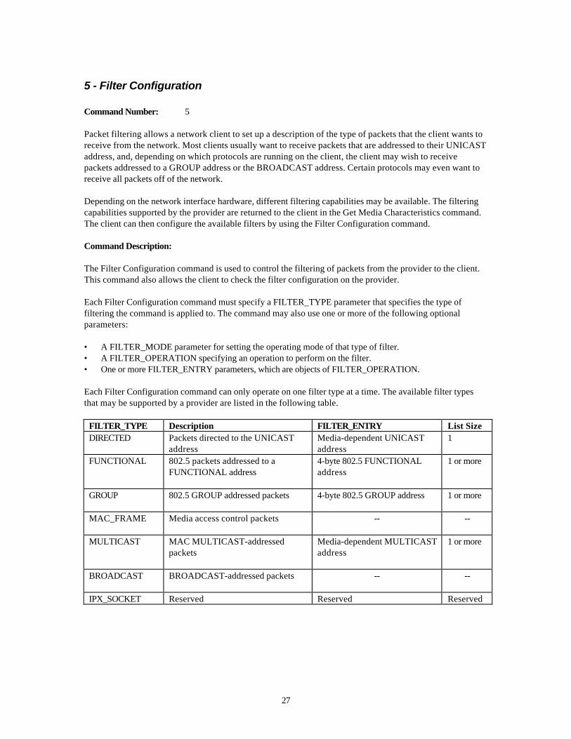
Packet filtering allows a network client to set up a description of the type of packets that the client wants toreceive from the network. Most clients usually want to receive packets that are addressed to their UNICASTaddress, and, depending on which protocols are running on the client, the client may wish to receivepackets addressed to a GROUP address or the BROADCAST address. Certain protocols may even want toreceive all packets off of the network.
Depending on the network interface hardware, different filtering capabilities may be available. The filteringcapabilities supported by the provider are returned to the client in the Get Media Characteristics command.The client can then configure the available filters by using the Filter Configuration command.
Command Description:
The Filter Configuration command is used to control the filtering of packets from the provider to the client.This command also allows the client to check the filter configuration on the provider.
Each Filter Configuration command must specify a FILTER_TYPE parameter that specifies the type offiltering the command is applied to. The command may also use one or more of the following optionalparameters:
• A FILTER_MODE parameter for setting the operating mode of that type of filter.• A FILTER_OPERATION specifying an operation to perform on the filter.• One or more FILTER_ENTRY parameters, which are objects of FILTER_OPERATION.
Each Filter Configuration command can only operate on one filter type at a time. The available filter typesthat may be supported by a provider are listed in the following table.
FILTER_TYPE Description FILTER_ENTRY List SizeDIRECTED Packets directed to the UNICAST
addressMedia-dependent UNICASTaddress
1
FUNCTIONAL 802.5 packets addressed to aFUNCTIONAL address
4-byte 802.5 FUNCTIONALaddress
1 or more
GROUP 802.5 GROUP addressed packets 4-byte 802.5 GROUP address 1 or more
MAC_FRAME Media access control packets -- --
MULTICAST MAC MULTICAST-addressedpackets
Media-dependent MULTICASTaddress
1 or more
BROADCAST BROADCAST-addressed packets -- --
IPX_SOCKET Reserved Reserved Reserved

28
Some of the filters can only be turned on or off, while others have an associated entry value(s):
• The BROADCAST and MAC_FRAME filters are either on or off and have no associated entry values.• The DIRECTED filter can only have one entry, which may either be set by the client or queried from the
provider.• The FUNCTIONAL, GROUP, and MULTICAST filters each have a list of values associated with them.
The setting of the list for a filter and the activation/deactivation of the filter are independent.
Each filter can be set to one of three modes. When the connection is first initiated, all the filters are in theNONE state. In the NONE state, no packets that meet the requirements of the filter are passed to the client.In the FILTER state, all packets that meet the requirements of the filter and that are found in the list ofaddresses for the filter are passed to the client. In the ALL state, all packets that meet the requirements ofthe filter are passed, regardless of whether they occur in the filter’s entry list. If a filter (such as theBROADCAST filter) has only two meaningful modes of operation, the FILTER and ALL states areequivalent.
Request Parameters:
Name Description Values DefaultValue
Instances Size
DATA_CHAN LSAP number ofthe data channel tobe modified
1-byte LSAP value -- 1 1
FILTER_TYPE Type of filter to bemodified
”DIRECTED",“FUNCTIONAL”,“GROUP”, “MACFRAME”,“MULTICAST”,“BROADCAST”, or“IPX_SOCKET”
-- 1 1-255
FILTER_MODE Filter operationmode
“ALL,” “FILTER,” or“NONE”
“NONE” 0-1 1-255
FILTER_OPERATION Operation toperform on thefilter’s pass list
“GET,” “CLEAR,”“ADD,” “REMOVE,”or “DYNAMIC”
“GET” 0-1 1-255
FILTER_ENTRY Entry to “ADD” or“REMOVE” fromthe filter’s pass list
Filter entry valueformat based onFILTER_TYPE
-- 0 or more 1-255
DATA_CHANLSAP number, obtained by using an earlier Open Data Channel command, that indicates the location ofthe filter on the provider.

29
FILTER_TYPEType of filter to be modified.
FILTER_MODEMode of the filter operation.
FILTER_OPERATIONOperation to perform on the filter’s pass list.
FILTER_ENTRYEntry to add or remove from the filter’s pass list.
Response Parameters:
Name Description Values DefaultValue
Instances Size
FILTER_MODE Current filter operationmode
“ALL,”“FILTER,” or“NONE”
“NONE” 0-1 1-255
FILTER_ENTRY On “DYNAMIC” or “GET”operations, provides thefilter entry list
Filter entry valueformat based onFILTER_TYPE
-- 0 or more 1-255
MAX_ENTRY Maximum number of entriesthat FILTER_TYPE in therequest supports
2-byte integer 0-1 2
FILTER_MODECurrent filter operation mode.
FILTER_ENTRYOn “DYNAMIC” or “GET” operations, provides the filter entry list.
MAX_ENTRYMaximum number of entries that FILTER_TYPE in the request supports.
For each of the different filter types, only certain filter operations and modes are valid. This information issummarized in the table that follows. (For more detailed information about the use of certain filter operationsand modes with different filter types, see the descriptions following the summary table. The descriptions areorganized by filter type.)

30
In the summary table that follows, an “X” in a column means that filter operation or filter mode can be usedwith the filter type named in the first column. For some filter types, the filter modes ALL and FILTER areequivalent; where that is the case, the X’s in the ALL and FILTER columns are shown to be equivalent withshading.
|ß Filter Operations à|ß Filter Modes à|
Filter Type GET CLEAR ADD REMOVE DYNAMIC ALL FILTER NONEDIRECTED X X X X X XFUNCTIONAL X X X X X XGROUP X X X X X X XMAC FRAME X X XMULTICAST X X X X X X XBROADCAST X X X
DIRECTED Filter Type:
Valid operations: ADD, GET, DYNAMICValid modes: FILTER, ALL, NONE (FILTER and ALL are equivalent)
The DIRECTED filter may be set, read, or dynamically assigned. Commands for the directed filter are issuedby setting the FILTER_TYPE field of the Filter Configuration command to “DIRECTED”.
To set the UNICAST address on which packets should be accepted, issue a Filter Configuration commandwith FILTER_OPERATION = “ADD” and FILTER_ENTRY = “desired address”.
To have the provider dynamically assign a UNICAST address to the client, issue a Filter Configurationcommand with FILTER_OPERATION = “DYNAMIC”.
To start accepting packets directed to the UNICAST address, issue a Filter Configuration command withFILTER_MODE=“FILTER”.
The current status of the DIRECTED filter can be queried by issuing a Filter Configuration request withFILTER_OPERATION=“GET”. The provider will return the current FILTER_MODE and the currentUNICAST address in the reply.
FUNCTIONAL Filter Type:
Valid operations: ADD, GET, CLEAR.Valid modes: FILTER, ALL, NONE
The functional address may be set or read. There is only one functional address per data channel. Thefunctional address is an bitwise OR operation of all the functional bits that all protocols wish to listen to.Commands for the FUNCTIONAL address filter are issued by setting the FILTER_TYPE field of the FilterConfiguration command to “FUNCTIONAL”.
To set the functional address on the provider, issue a Filter Configuration command withFILTER_OPERATION = “ADD” and FILTER_ENTRY = “desired functional address”.
To enable reception of a frame on the current functional address, issue a Filter Configuration command withFILTER_MODE = “FILTER”. Setting the FILTER_MODE parameter to ALL is equivalent to setting

31
FILTER_MODE to FILTER with FILTER_ENTRY = FF-FF-FF-FF, because either setting will accept allpackets addressed to any functional address.
The current status of the FUNCTIONAL filter can be queried by issuing a Filter Configuration commandwith FILTER_OPERATION=“GET”. The provider will return the current FILTER_MODE and the currentfunctional address in the response packet. If the functional address has not yet been set, the provider mayreturn the current address as 00-00-00-00, because this is equivalent to the FUNCTIONAL filter being set tonot accept any functional packets.
GROUP Filter Type:
Valid operations: ADD, GET, CLEAR, REMOVEValid modes: FILTER, ALL, NONE
The GROUP address list may either be set or read, and be turned ON or OFF or be set to accept packetsdirected to any GROUP address. Commands for the GROUP address filter are issued by setting theFILTER_TYPE field of the Filter Configuration command to “GROUP”.
To add a list of GROUP addresses on the provider, issue a Filter Configuration command withFILTER_OPERATION = “ADD” and one or more FILTER_ENTRY parameters. Adding entries will notremove the previous entries in the list, so the client must be sure to keep track of and clear out expiredentries.
To remove all entries from the GROUP address list on the provider, issue a Filter Configuration commandwith FILTER_OPERATION=“CLEAR”. Using the CLEAR operation instead of the REMOVE operation cansometimes help make the maintenance of the GROUP address list easier for the client.
To remove some of the entries from the GROUP address list on the provider, issue a Filter Configurationcommand with FILTER_OPERATION = “REMOVE” and one or more FILTER_ENTRY parameters specifyingwhich addresses should be removed.
All frames addressed to GROUP addresses can be received by setting the FILTER_MODE of the GROUPaddress filter to ALL.
The current status of the GROUP address filter can be queried by issuing a Filter Configuration commandwith FILTER_OPERATION=“GET”. The provider will return the current FILTER_MODE and the current listof GROUP addresses, as well as the maximum number of GROUP address entries that the provider supports.
MAC_FRAME Filter Type:
Valid operations:Valid modes: FILTER, ALL, NONE (FILTER and ALL are equivalent)
The reception of MAC_FRAME frames on the 802.5 media can only be turned ON or OFF. Commands forthe MAC_FRAME filter are issued by setting the FILTER_TYPE field of the Filter Configuration commandto “MAC_FRAME”.
To turn the reception of MAC_FRAME frames on, issue a Filter Configuration command withFILTER_MODE = “FILTER” or FILTER_MODE = “ALL”. To disable the reception of MAC_FRAME frames,issue a Filter Configuration command with FILTER_MODE = “NONE”
The current status of the MAC_FRAME filter can be queried by issuing a Filter Configuration commandwith FILTER_OPERATION=“GET”. The provider will return the current FILTER_MODE.

32
MULTICAST Filter Type:
Valid operations: ADD, GET, CLEAR, REMOVEValid modes: FILTER, ALL, NONE
The MULTICAST address list may be either set or read, and be turned ON or OFF or be set to acceptpackets directed to any MULTICAST address. Commands for the MULTICAST address filter are issued bysetting the FILTER_TYPE parameter of the Filter Configuration command to “MULTICAST”.
To add a list of MULTICAST addresses on the provider, issue a Filter Configuration command withFILTER_OPERATION = “ADD” and one or more FILTER_ENTRY parameters. Adding entries will notremove the previous entries in the list, so the client must be sure to keep track of and clear out expiredentries.
To remove all entries from the MULTICAST address list on the provider, issue a Filter Configurationcommand with FILTER_OPERATION=“CLEAR”. Using the CLEAR operation instead of the REMOVEoperation can sometimes help make the maintenance of the MULTICAST address list easier for the client.
To remove some of the entries from the MULTICAST address list on the provider, issue a FilterConfiguration command with FILTER_OPERATION = “REMOVE” and one or more FILTER_ENTRYparameters specifying which addresses should be removed.
All frames addressed to MULTICAST addresses can be received by setting the FILTER_MODE of theMULTICAST address filter to ALL.
The current status of the MULTICAST address filter can be queried by issuing a Filter Configurationrequest with FILTER_OPERATION=“GET”. The provider will return the current FILTER_MODE and thecurrent list of MULTICAST addresses as well as the MAXIMUM number of MULTICAST address entriesthat the provider supports.
BROADCAST Filter Type:
Valid operations: None.Valid modes: FILTER, ALL, NONE (FILTER and ALL are equivalent)
The reception of BROADCAST frames can only be ON or OFF. Commands for the BROADCAST filter areissued by setting the FILTER_TYPE parameter of the Filter Configuration command to “BROADCAST”.
To turn the reception of BROADCAST frames on, issue a Filter Configuration command withFILTER_MODE = “FILTER” or FILTER_MODE = “ALL”. To disable the reception of BROADCAST frames,issue a Filter Configuration command with FILTER_MODE = “NONE”.
The current status of the BROADCAST filter can be queried by issuing a Filter Configuration command withFILTER_OPERATION=“GET”. The provider will return the current FILTER_MODE.
Example Filter Configuration Commands:
COMMAND:
Get a UNICAST address.
3 parametersDATA_CHAN = <LSAP:02>

33
FILTER_TYPE = “DIRECTED”FILTER_OPERATION = “DYNAMIC”
0000: 05 03 09 44 41 54 41 5f 43 48 41 4e 01 00 02 0b0010: 46 49 4c 54 45 52 5f 54 59 50 45 08 00 44 49 520020: 45 43 54 45 44 10 46 49 4c 54 45 52 5f 4f 50 450030: 52 41 54 49 4f 4e 07 00 44 59 4e 41 4d 49 43
0000: .. .. .. D A T A _ C H A N .. .. .. ..0010: F I L T E R _ T Y P E .. .. D I R0020: E C T E D F I L T E R _ O P E0030: R A T I O N .. .. D Y N A M I C
RESPONSE:
Status = 0 (Success)
3 parameters
FILTER_MODE = ”NONE”MAX_ENTRY = 1FILTER_ENTRY = <00 08 00 09 97 23 54>
The directed filter is off, only 1 directed filter can be set at a time,and the UNICAST address is 00-08-00-09-97-23-57
0000: 00 03 0b 46 49 4c 54 45 52 5f 4d 4f 44 45 04 000010: 4e 4f 4e 45 09 4d 41 58 5f 45 4e 54 52 59 02 000020: 01 00 0c 46 49 4c 54 45 52 5f 45 4e 54 52 59 060030: 00 08 00 09 97 23 540000: .. .. .. F I L T E R _ M O D E .. ..0010: N O N E .. M A X _ E N T R Y .. ..0020: .. .. .. F I L T E R _ E N T R Y ..0030: .. .. .. .. # T
COMMAND:
Get the state of the provider MULTICAST list
3 parametersDATA_CHAN = <LSAP:02>FILTER_OPERATION = “GET”FILTER_TYPE = “MULTICAST”
0000: 05 03 09 44 41 54 41 5f 43 48 41 4e 01 00 02 100010: 46 49 4c 54 45 52 5f 4f 50 45 52 41 54 49 4f 4e0020: 03 00 47 45 54 0b 46 49 4c 54 45 52 5f 54 59 500030: 45 09 00 4d 55 4c 54 49 43 41 53 54
0000: .. .. .. D A T A _ C H A N .. .. .. ..0010: F I L T E R _ O P E R A T I O N0020: .. .. G E T .. F I L T E R _ T Y P
34
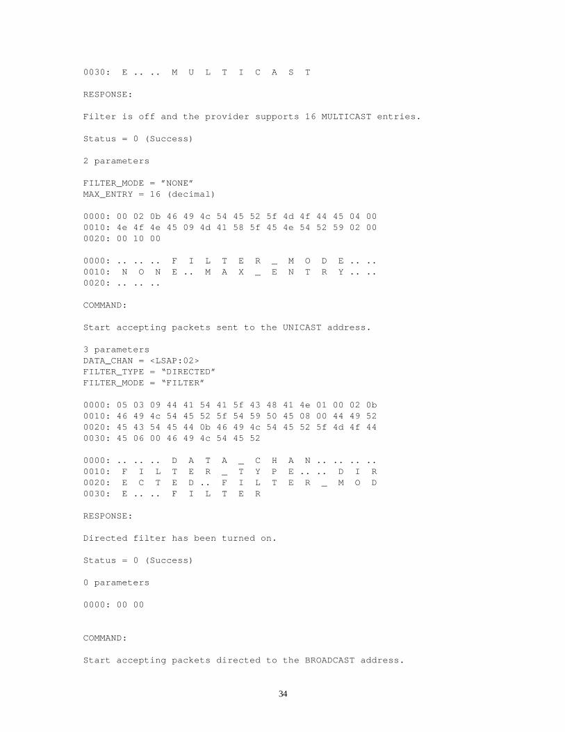
0030: E .. .. M U L T I C A S T
RESPONSE:
Filter is off and the provider supports 16 MULTICAST entries.
Status = 0 (Success)
2 parameters
FILTER_MODE = ”NONE”MAX_ENTRY = 16 (decimal)
0000: 00 02 0b 46 49 4c 54 45 52 5f 4d 4f 44 45 04 000010: 4e 4f 4e 45 09 4d 41 58 5f 45 4e 54 52 59 02 000020: 00 10 00
0000: .. .. .. F I L T E R _ M O D E .. ..0010: N O N E .. M A X _ E N T R Y .. ..0020: .. .. ..
COMMAND:
Start accepting packets sent to the UNICAST address.
3 parametersDATA_CHAN = <LSAP:02>FILTER_TYPE = “DIRECTED”FILTER_MODE = “FILTER”
0000: 05 03 09 44 41 54 41 5f 43 48 41 4e 01 00 02 0b0010: 46 49 4c 54 45 52 5f 54 59 50 45 08 00 44 49 520020: 45 43 54 45 44 0b 46 49 4c 54 45 52 5f 4d 4f 440030: 45 06 00 46 49 4c 54 45 52
0000: .. .. .. D A T A _ C H A N .. .. .. ..0010: F I L T E R _ T Y P E .. .. D I R0020: E C T E D .. F I L T E R _ M O D0030: E .. .. F I L T E R
RESPONSE:
Directed filter has been turned on.
Status = 0 (Success)
0 parameters
0000: 00 00
COMMAND:
Start accepting packets directed to the BROADCAST address.

35
3 parametersDATA_CHAN = <LSAP:02>FILTER_TYPE = “BROADCAST”FILTER_MODE = “FILTER”
0000: 05 03 09 44 41 54 41 5f 43 48 41 4e 01 00 02 0b0010: 46 49 4c 54 45 52 5f 54 59 50 45 09 00 42 52 4f0020: 41 44 43 41 53 54 0b 46 49 4c 54 45 52 5f 4d 4f0030: 44 45 06 00 46 49 4c 54 45 52
0000: .. .. .. D A T A _ C H A N .. .. .. ..0010: F I L T E R _ T Y P E .. .. B R O0020: A D C A S T .. F I L T E R _ M O0030: D E .. .. F I L T E R
RESPONSE:
BROADCAST packets are now being accepted.
Status = 0 (Success)0 parameters
0000: 00 00COMMAND
Clear the MULTICAST filter list on the provider.
3 parametersDATA_CHAN = <LSAP:02>FILTER_OPERATION = “CLEAR”FILTER_TYPE = “MULTICAST”
0000: 05 03 09 44 41 54 41 5f 43 48 41 4e 01 00 02 100010: 46 49 4c 54 45 52 5f 4f 50 45 52 41 54 49 4f 4e0020: 05 00 43 4c 45 41 52 0b 46 49 4c 54 45 52 5f 540030: 59 50 45 09 00 4d 55 4c 54 49 43 41 53 54
0000: .. .. .. D A T A _ C H A N .. .. .. ..0010: F I L T E R _ O P E R A T I O N0020: .. .. C L E A R .. F I L T E R _ T0030: Y P E .. .. M U L T I C A S T
RESPONSE:
MULTICAST List has been cleared
0000: 00 00
COMMAND
Add the MULTICAST entry 01-00-5e-00-00-01 to the MULTICAST list on theprovider and turn on MULTICAST filtering.

36
5 parametersDATA_CHAN = <LSAP:02>FILTER_OPERATION = “ADD”FILTER_MODE = “FILTER”FILTER_TYPE = “MULTICAST”FILTER_ENTRY = <01 00 5e 00 00 01>
0000: 05 05 09 44 41 54 41 5f 43 48 41 4e 01 00 02 100010: 46 49 4c 54 45 52 5f 4f 50 45 52 41 54 49 4f 4e0020: 03 00 41 44 44 0b 46 49 4c 54 45 52 5f 4d 4f 440030: 45 06 00 46 49 4c 54 45 52 0b 46 49 4c 54 45 520040: 5f 54 59 50 45 09 00 4d 55 4c 54 49 43 41 53 540050: 0c 46 49 4c 54 45 52 5f 45 4e 54 52 59 06 00 010060: 00 5e 00 00 01
0000: .. .. .. D A T A _ C H A N .. .. .. ..0010: F I L T E R _ O P E R A T I O N0020: .. .. A D D .. F I L T E R _ M O D0030: E .. .. F I L T E R .. F I L T E R0040: _ T Y P E .. .. M U L T I C A S T0050: .. F I L T E R _ E N T R Y .. .. ..0060: .. D .. .. ..
RESPONSE:
The entry has been added to the list, and MULTICAST filtering is on.
0000: 00 00
37
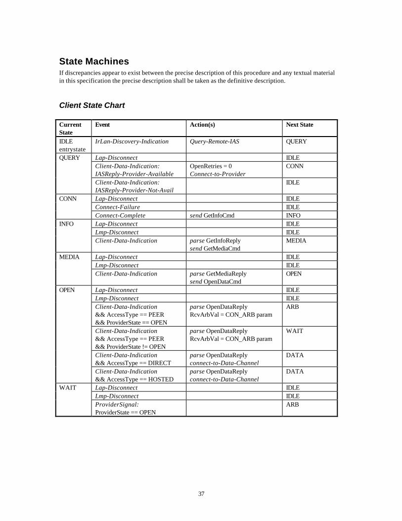
State MachinesIf discrepancies appear to exist between the precise description of this procedure and any textual materialin this specification the precise description shall be taken as the definitive description.
Client State Chart
CurrentState
Event Action(s) Next State
IDLEentrystate
IrLan-Discovery-Indication Query-Remote-IAS QUERY
QUERY Lap-Disconnect IDLEClient-Data-Indication:IASReply-Provider-Available
OpenRetries = 0Connect-to-Provider
CONN
Client-Data-Indication:IASReply-Provider-Not-Avail
IDLE
CONN Lap-Disconnect IDLEConnect-Failure IDLEConnect-Complete send GetInfoCmd INFO
INFO Lap-Disconnect IDLELmp-Disconnect IDLEClient-Data-Indication parse GetInfoReply
send GetMediaCmdMEDIA
MEDIA Lap-Disconnect IDLELmp-Disconnect IDLEClient-Data-Indication parse GetMediaReply
send OpenDataCmdOPEN
OPEN Lap-Disconnect IDLELmp-Disconnect IDLEClient-Data-Indication&& AccessType == PEER&& ProviderState == OPEN
parse OpenDataReplyRcvArbVal = CON_ARB param
ARB
Client-Data-Indication&& AccessType == PEER&& ProviderState != OPEN
parse OpenDataReplyRcvArbVal = CON_ARB param
WAIT
Client-Data-Indication&& AccessType == DIRECT
parse OpenDataReplyconnect-to-Data-Channel
DATA
Client-Data-Indication&& AccessType == HOSTED
parse OpenDataReplyconnect-to-Data-Channel
DATA
WAIT Lap-Disconnect IDLELmp-Disconnect IDLEProviderSignal:ProviderState == OPEN
ARB

38
CurrentState
Event Action(s) Next State
ARB Lap-Disconnect IDLELmp-Disconnect IDLESendArbVal == RcvArbVal send CloseDataCmd CLOSESendArbVal > RcvArbVal connect-Data-Channel
enable-data-transferDATA
SendArbVal < RcvArbVal ARBData-Connect-Indication enable-data-transfer DATA
DATA Lap-Disconnect disable-data-transfer IDLELmp-Disconnect disable-data-transfer
disconnect-Data-ChannelIDLE
Data-Chan-Disconnect disconnect-Provider IDLECLOSE Lap-Disconnect IDLE
Lmp-Disconnect IDLEClient-Data-Indication&& ProviderState == OPEN
parse DataCloseReply SYNC
Client-Data-Indication&& ProviderState != OPEN&& OpenRetries < ORMax
parse DataCloseReplyOpenRetries = OpenRetries + 1send OpenDataCmd
OPEN
Client-Data-Indication&& ProviderState != OPEN&& OpenRetries >= ORMax
parse DataCloseReply IDLE
SYNC Lap-Disconnect IDLELmp-Disconnect IDLEProviderSignal:ProviderState != OPEN&& OpenRetries < ORMax
OpenRetries = OpenRetries + 1send OpenDataCmd
OPEN
ProviderSignal:ProviderState != OPEN&& OpenRetries >= ORMax
IDLE
Notes
1. Logical operators in the state table are defined as follows:A == B: A equals B.A != B: A does not equal B.A < B: A is less than B.A >= B: A is greater than or equal to B.A && B: A logically ANDed with B.
Client State Definitions
IDLE. The LAN client is waiting for indication that there is a provider in the IR cone.
CONN. The client has connected to a provider but has not issued any commands.
INFO. The client has issued a GetInfo command and is awaiting a reply.

39
MEDIA. The client has issued a GetMedia command and is awaiting a reply.
OPEN. The client has issued a OpenData command and is awaiting a reply.
WAIT. The client is waiting for the local provider to enter the provider OPEN state.
ARB. The client compares the DataOpen arbitration value it sent to the remote provider to the valuereceived by the local provider and acts accordingly.
DATA. The data channel is connected, allowing data transfers between the local and remote machines.
CLOSE. The client has issued a DataClose command and is awaiting a reply.
SYNC. The client is waiting for the local provider to exit the provider OPEN state.
Client Event Descriptions
IrLan-Discovery-Indication. A device with the IrLAN hint bit set has been discovered.
Lap-Disconnect. An IrLap connection has ended.
Client-Data-Indication. A data packet has been received by the IrLan client LSAP.
IASReply-Provider-Available. The remote IAS reply indicates an IrLan provider is supported.
IASReply-Provider-Not-Avail. The remote IAS reply indicates an IrLan provider is not supported
Connect-Complete. The requested connection is available for use.
Connect-Failure. The connect request has failed.
Lmp-Disconnect. The IrLmp(e.g. IrLan Client LSAP - IrLan Provider LSAP) connection has ended.
AccessType == PEER. The method of IrLan access selected is Peer-to-Peer with each side having a clientand a provider.
AccessType == DIRECT. The method of IrLan access selected is Access Point with a client on one side anda provider on the other.
AccessType == HOSTED. The method of IrLan access selected is Hosted mode with a client on one sideand a provider on the other.
ProviderSignal: ProviderState == OPEN. The local provider is signaling that it is entering the OPEN state.
ProviderSignal: ProviderState != OPEN. The local provider is signaling that it is leaving the OPEN state.
SendArbVal == RcvArbVal. The CON_ARB value sent by the local provider is equal to the CON_ARBvalue received by the client in the reply to the Open Data Channel command.

40
Data-Connect-Indication. The remote station has connected to the local data channel LSAP.
Data-Chan-Disconnect. The remote station has disconnected from the local data channel LSAP.
ProviderState == OPEN. The local provider is in the OPEN state.
OpenRetries < ORMax. The open retry count is less than the maximum allowed.
Client Action Descriptions
Query-Remote-IAS. Query the remote IAS for the presence of an IrLan provider.
OpenRetries = 0. Set the OpenRetries variable to 0.
Connect-to-Provider. Perform an IrLMP connect from the local IrLan Client LSAP to the remote IrLanprovider LSAP.
send GetInfoCmd. Send an IrLan Get Provider Information command to the remote IrLan provider LSAP.
send GetMediaCmd. Send an IrLan Get Media Characteristics command to the remote IrLan provider LSAP.
send OpenDataCmd. Send an IrLan Open Data Channel command to the remote IrLan provider LSAP.
send CloseDataCmd. Send an IrLan Close Data Channel command to the remote IrLan provider LSAP.
parse xxxReply. Extract any parameters from a reply to an IrLan command, checking for errors.
RcvArbVal = CON_ARB param. Load the CON_ARB parameter from reply to the IrLan Data OpenCommand into the RcvArbVal variable.
connect-Data-Channel. Perform an IrLMP connect from the local IrLan Data Channel LSAP to the remoteIrLan Data Channel LSAP.
enable-data-transfer. Allow data transfers to occur across the data channel.
disable-data-transfer. Disallow sending and receiving data on the data channel.
disconnect-Data-Channel. Perform an IrLMP disconnect from the local IrLan Data Channel LSAP to theremote IrLan Data Channel LSAP.
disconnect-Provider. Perform an IrLMP disconnect from the remote IrLan Provider LSAP.
OpenRetries = OpenRetries + 1. Increment the OpenRetries variable.

41
Provider State Chart
CurrentState
Event Action(s) Next State
IDLE(entry state)
Connect-Indication INFO
INFO Lap-Disconnect IDLELmp-Disconnect IDLEProvider-Data-Indication:GetInfoCmd
if( ProviderAccess == PEER)then
MEDIA = “802.3”send GetInfoReply
INFO
Provider-Data-Indication:GetMediaCmd
parse GetMediaCmdsend GetMediaReply
INFO
Provider-Data-Indication:OpenDataCmd
if( AccessType == PEER ) then generate SendArbVal CON_ARB param =
SendArbValsend OpenDataReplysignal client: State == OPEN
OPEN
OPEN Lap-Disconnect IDLELmp-Disconnect IDLEProvider-Data-Indication:GetInfoCmd
send GetInfoReply OPEN
Provider-Data-Indication:GetMediaCmd
parse GetMediaCmdsend GetMediaReply
OPEN
Provider-Data-Indication:CloseDataCmd
parse CloseDataCmdsend CloseDataReplysignal client: State != OPEN
INFO
Provider-Data-Indication:FilterConfigCmd
parse FilterConfigCmdsend FlterConfigReply
OPEN
Data-Connect-Indication DATADATA Lap-Disconnect IDLE
Lmp-Disconnect IDLEData-Chan-Disconnect INFOProvider-Data-Indication:CloseDataCmd
disable-data-transfersend CloseDataReply
INFO
Provider-Data-Indication:GetInfoCmd
send GetInfoReply DATA
Provider-Data-Indication:GetMediaCmd
parse GetMediaCmdsend GetMediaReply
DATA
Provider-Data-Indication:FilterConfigCmd
parse FilterConfigCmdsend FlterConfigReply
DATA
42
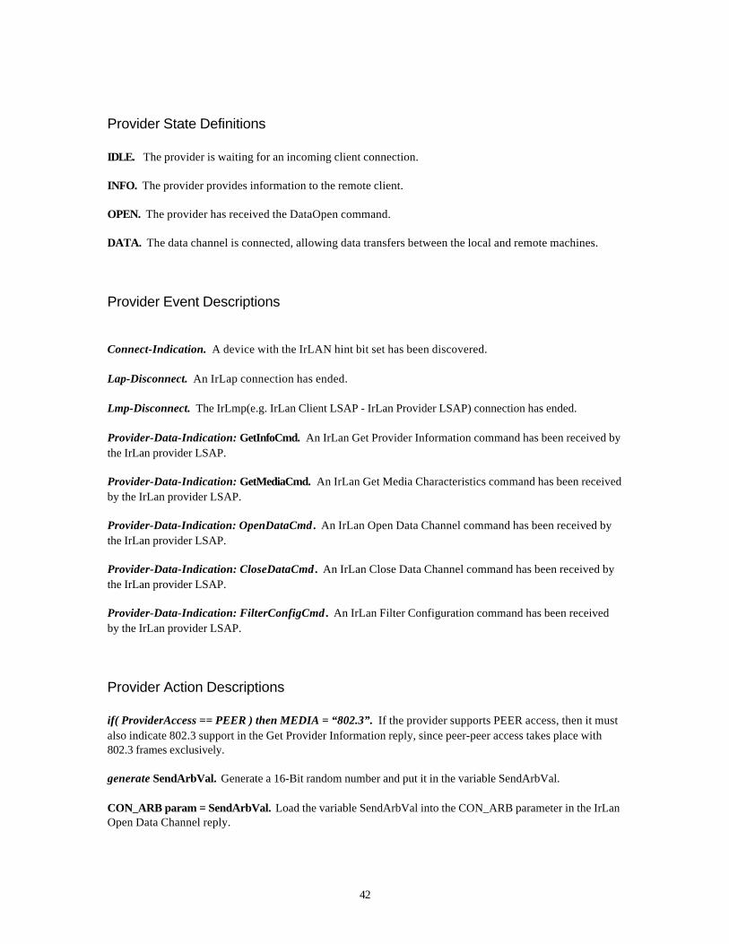
Provider State Definitions
IDLE. The provider is waiting for an incoming client connection.
INFO. The provider provides information to the remote client.
OPEN. The provider has received the DataOpen command.
DATA. The data channel is connected, allowing data transfers between the local and remote machines.
Provider Event Descriptions
Connect-Indication. A device with the IrLAN hint bit set has been discovered.
Lap-Disconnect. An IrLap connection has ended.
Lmp-Disconnect. The IrLmp(e.g. IrLan Client LSAP - IrLan Provider LSAP) connection has ended.
Provider-Data-Indication: GetInfoCmd. An IrLan Get Provider Information command has been received bythe IrLan provider LSAP.
Provider-Data-Indication: GetMediaCmd. An IrLan Get Media Characteristics command has been receivedby the IrLan provider LSAP.
Provider-Data-Indication: OpenDataCmd . An IrLan Open Data Channel command has been received bythe IrLan provider LSAP.
Provider-Data-Indication: CloseDataCmd . An IrLan Close Data Channel command has been received bythe IrLan provider LSAP.
Provider-Data-Indication: FilterConfigCmd . An IrLan Filter Configuration command has been receivedby the IrLan provider LSAP.
Provider Action Descriptions
if( ProviderAccess == PEER ) then MEDIA = “802.3”. If the provider supports PEER access, then it mustalso indicate 802.3 support in the Get Provider Information reply, since peer-peer access takes place with802.3 frames exclusively.
generate SendArbVal. Generate a 16-Bit random number and put it in the variable SendArbVal.
CON_ARB param = SendArbVal. Load the variable SendArbVal into the CON_ARB parameter in the IrLanOpen Data Channel reply.

43
signal client: State = OPEN. Signal the local IrLan client state machine that the provider state machine isentering the OPEN state.
signal client: State != OPEN. Signal the local IrLan client state machine that the provider state machine isleaving the OPEN state.
send GetInfoReply. Send an IrLan Get Provider Information reply to the remote IrLan client LSAP.
send GetMediaReply. Send an IrLan Get Media Characteristics reply to the remote IrLan client LSAP.
send OpenDataReply. Send an IrLan Open Data Channel reply to the remote IrLan client LSAP.
send CloseDataReply. Send an IrLan Close Data Channel reply to the remote IrLan client LSAP.
parse xxxCmd . Extract any parameters from an IrLan command, checking for errors.
disable-data-transfer. Disallow sending and receiving data on the data channel.
RcvArbVal = CON_ARB param. Load the CON_ARB parameter from reply to the IrLan Data OpenCommand into the RcvArbVal variable.
Peer-to-Peer Mode Considerations
Data-Channel Frame FormatsPeer-to-Peer mode is defined to support only the 802.3 (Ethernet) frame format.
MacAddress GenerationIn connections where an IrLan Access Point is acting as the IrLan Provider, the Access Point contains ahard coded MacAddress which it returns to the IrLan Client in response to the “DIRECT “ “GET” or“DIRECT” “DYNAMIC” FILTER commands. The IrLan Client may then pass this address to the upper levelprotocols when they request the MacAddress.
In the case of a Peer-to-Peer connection it is probable that no hard coded MacAddress exists. Thus thePeer Provider must provide some means of generating a locally unique (unique to the current peer network)MacAddress which may be returned to the IrLan Client.
8 bits
Peer-to-Peer MacAddress Specification
24 bits 16 bits
48 bit address
0100 0000 24 bits of 0s Connect ionarbitration
value
Sample Address:40.00.00.00.A4.78

44
Since the address is local, the Peer-to-Peer address generation algorithm takes advantage of the 802.3 frameformat’s locally administered address bit. As the MacAddress is not required to be generated until afterconnection arbitration has completed we have a convenient access to a 16 bit value that is guaranteed to beunique. Thus the Peer-to-Peer address shall consist of 6 bytes where the high 4 bytes are all 0 except for thesecond bit of the first byte which is set to 1 to specify a locally administered address. The lower 2 bytes ofthe address are the arbitration value that was generated during the connection arbitration process.
Example Peer Mode Initial Conversation and Arbitration
PEER 1: COMMANDGetProviderInformation0 parameters
0000: 00 00
0000: .. ..
PEER 2: RESPONSEStatus = 0 (Success)
2 parametersMEDIA = "802.3"IRLAN_VER = 1.1
0001: 00 02 05 4D 45 44 49 41 05 00 38 30 32 2E 33 090002: 49 52 4C 41 4E 5F 56 45 52 02 00 01 01
0001: .. .. .. M E D I A .. .. 8 0 2 . 3 ..0002: I R L A N _ V E R .. .. .. ..
PEER 2: COMMANDGetProviderInformation0 parameters
0003: 00 00
0003: .. ..
PEER 1: RESPONSEStatus = 0 (Success)
2 parametersMEDIA = "802.3"IRLAN_VER = 1.1
0004: 00 02 05 4D 45 44 49 41 05 00 38 30 32 2E 33 090005: 49 52 4C 41 4E 5F 56 45 52 02 00 01 01
0004: .. .. .. M E D I A .. .. 8 0 2 . 3 ..

45
0005: I R L A N _ V E R .. .. .. ..
PEER 1: COMMANDGetMediaCharacteristics1 parameterMEDIA = "802.3"
0006: 01 01 05 4D 45 44 49 41 05 00 38 30 32 2E 33
0006: .. .. .. M E D I A .. .. 8 0 2 . 3
PEER 2: COMMANDGetMediaCharacteristics1 parameterMEDIA = "802.3"
0007: 01 01 05 4D 45 44 49 41 05 00 38 30 32 2E 33
0007: .. .. .. M E D I A .. .. 8 0 2 . 3
PEER 2: RESPONSEStatus = 0 (Success)
5 parametersFILTER_TYPE = "DIRECTED"FILTER_TYPE = "MULTICAST"FILTER_TYPE = "BROADCAST"MAX_FRAME = 0x05EA (1514d)ACCESS_TYPE = "PEER"
0008: 00 05 0B 46 49 4C 54 45 52 5F 54 59 50 45 08 000009: 44 49 52 45 43 54 45 44 0B 46 49 4C 54 45 52 5F0010: 54 59 50 45 09 00 4D 55 4C 54 49 43 41 53 54 0B0011: 46 49 4C 54 45 52 5F 54 59 50 45 09 00 42 52 4F0012: 41 44 43 41 53 54 09 4D 41 58 5F 46 52 41 4D 450013: 02 00 EA 05 0B 41 43 43 45 53 53 5F 54 59 50 450014: 04 00 50 45 45 52
0008: .. .. .. F I L T E R _ T Y P E .. ..0009: D I R E C T E D .. F I L T E R _0010: T Y P E .. .. M U L T I C A S T ..0011: F I L T E R _ T Y P E .. B R O A0012: D C A S T .. M A X _ F R A M E ..0013: .. .. .. .. .. A C C E S S _ T Y P E0014: .. .. P E E R
PEER 1: RESPONSEStatus = 0 (Success)
5 parameters

46
FILTER_TYPE = "DIRECTED"FILTER_TYPE = "MULTICAST"FILTER_TYPE = "BROADCAST"MAX_FRAME = 0x05EA (1514d)ACCESS_TYPE = "PEER"
0015: 00 05 0B 46 49 4C 54 45 52 5F 54 59 50 45 08 000016: 44 49 52 45 43 54 45 44 0B 46 49 4C 54 45 52 5F0017: 54 59 50 45 09 00 4D 55 4C 54 49 43 41 53 54 0B0018: 46 49 4C 54 45 52 5F 54 59 50 45 09 00 42 52 4F0019: 41 44 43 41 53 54 09 4D 41 58 5F 46 52 41 4D 450020: 02 00 EA 05 0B 41 43 43 45 53 53 5F 54 59 50 450021: 04 00 50 45 45 52
0015: .. .. .. F I L T E R _ T Y P E .. ..0016: D I R E C T E D .. F I L T E R _0017: T Y P E .. .. M U L T I C A S T ..0018: F I L T E R _ T Y P E .. B R O A0019: D C A S T .. M A X _ F R A M E ..0020: .. .. .. .. .. A C C E S S _ T Y P E0021: .. .. P E E R
PEER 1: COMMANDOpenDataChannel2 parametersMEDIA = "802.3"ACCESS_TYPE = "PEER"
0022: 02 02 05 4D 45 44 49 41 05 00 38 G2 30 32 2E 330023: 0B 41 43 43 45 53 53 5F 54 59 50 45 04 00 50 450024: 45 52
0022: .. .. .. M E D I A .. .. 8 0 2 . 3 ..0023: .. A C C E S S _ T Y P E .. .. P E0024: E R
PEER 2: COMMANDOpenDataChannel2 parametersMEDIA = "802.3"ACCESS_TYPE = "PEER"
0025: 02 02 05 4D 45 44 49 41 05 00 38 G2 30 32 2E 330026: 0B 41 43 43 45 53 53 5F 54 59 50 45 04 00 50 450027: 45 52
0025: .. .. .. M E D I A .. .. 8 0 2 . 3 ..0026: .. A C C E S S _ T Y P E .. .. P E0027: E R
PEER 2: RESPONSE

47
Status = 0 (Success)
3 ParametersDATA_CHAN = <LSAP:06>RECONNECT_KEY = 00 40 68 00 09 97 00 00 01 00CON_ARB = 0x9709 (38665)
0028: 00 03 09 44 41 54 41 5F 43 48 41 4E 01 00 06 0D0029: 52 45 43 4F 4E 4E 45 43 54 5F 4B 45 59 0A 00 000030: 40 68 00 09 97 00 00 01 00 07 43 4F 4E 5F 41 520031: 42 02 00 09 97
0028: .. .. .. D A T A _ C H A N .. .. .. ..0029: R E C O N N E C T _ K E Y .. .. ..0030: .. .. .. .. .. .. .. .. .. .. C O N _ A R0031: B .. .. .. ..
PEER 1: RESPONSEStatus = 0 (Success)
3 ParametersDATA_CHAN = <LSAP:06>RECONNECT_KEY = 00 40 68 00 B9 6A 00 00 01 00CON_ARB = 0x6AB9 (27321)
0032: 00 03 09 44 41 54 41 5F 43 48 41 4E 01 00 06 0D0033: 52 45 43 4F 4E 4E 45 43 54 5F 4B 45 59 0A 00 000034: 40 68 00 09 97 00 00 01 00 07 43 4F 4E 5F 41 520035: 42 02 00 B9 6A
0032: .. .. .. D A T A _ C H A N .. .. .. ..0033: R E C O N N E C T _ K E Y .. .. ..0034: .. .. .. .. .. .. .. .. .. .. C O N _ A R0035: B .. .. .. ..
At this point in the conversation both sides know that PEER 2 has won the arbitration process, since it hasthe higher arbitration value. Additionally, PEER 2 is aware that PEER 1’s data channel is on LSAP 6. ThusPEER 1 will wait for PEER 2 to open a channel on its LSAP 6. Note that both PEERs may perform a numberof other actions, such as setting filters, before PEER 2 issues its connect request.